Embed Size (px)
Citation preview
Revised March 2007
HIGHWAY PRODUCTSTRINITY
1
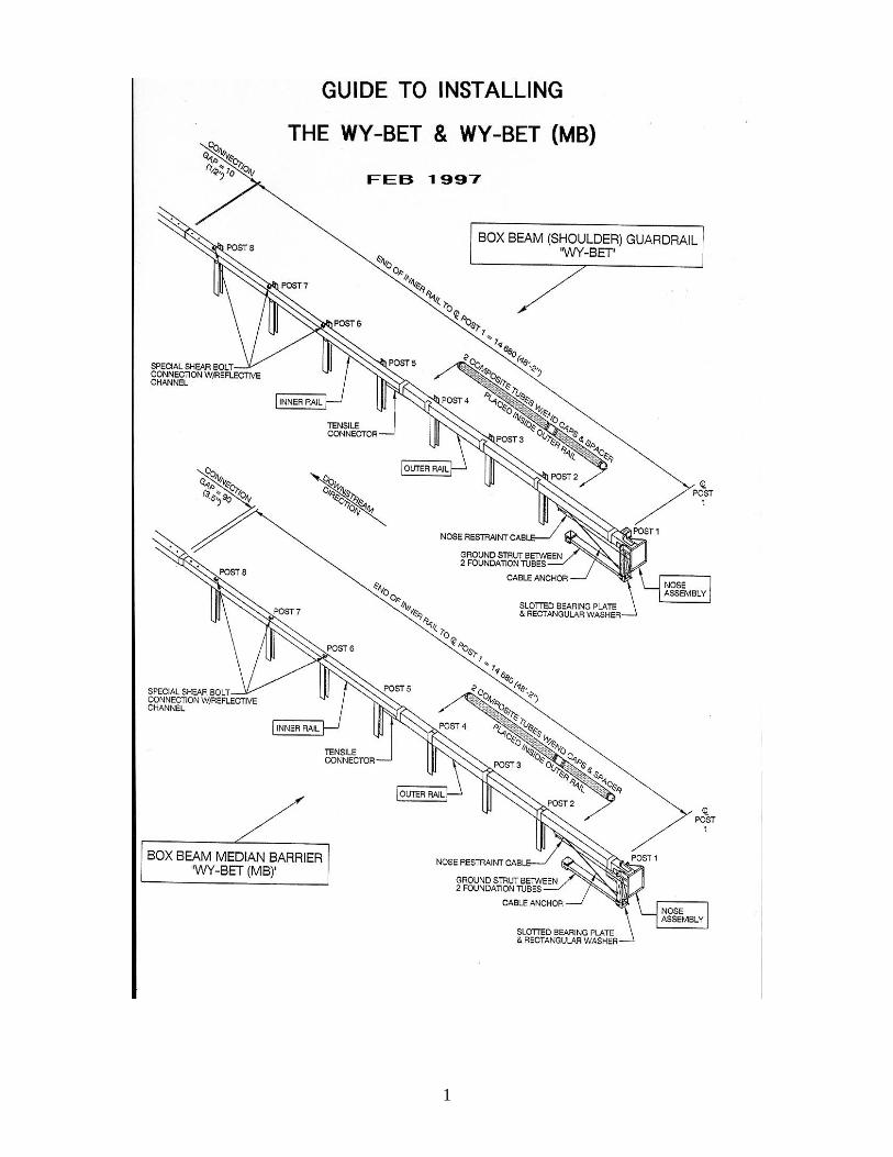
The following is an installation guide to assist contractors, filed inspectors and maintenance personnel to insure proper installation and maintenance of WY-BET End Terminals. The installer and/or inspector should be familiar with the standard plans and the project plans and use them together with this guide to insure proper installation. This document does not waive nor does it override the specifications. All dimensions in this document are in millimeters unless otherwise shown. For convenience, English dimensions have been shown in parenthesis.
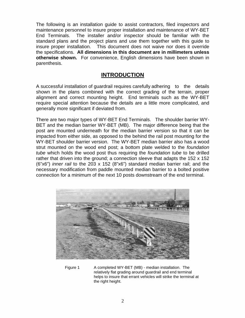
INTRODUCTION A successful installation of guardrail requires carefully adhering to the details shown in the plans combined with the correct grading of the terrain, proper alignment and correct mounting height. End terminals such as the WY-BET require special attention because the details are a little more complicated, and generally more significant if deviated from. There are two major types of WY-BET End Terminals. The shoulder barrier WY-BET and the median barrier WY-BET (MB). The major difference being that the post are mounted underneath for the median barrier version so that it can be impacted from either side, as opposed to the behind the rail post mounting for the WY-BET shoulder barrier version. The WY-BET median barrier also has a wood strut mounted on the wood end post; a bottom plate welded to the foundation tube which holds the wood post thus requiring the foundation tube to be drilled rather that driven into the ground; a connection sleeve that adapts the 152 x 152 (6”x6”) inner rail to the 203 x 152 (8”x6”) standard median barrier rail; and the necessary modification from paddle mounted median barrier to a bolted positive connection for a minimum of the next 10 posts downstream of the end terminal.
Figure 1 A completed WY-BET (MB) - median installation. The relatively flat grading around guardrail and end terminal helps to insure that errant vehicles will strike the terminal at the right height.
2
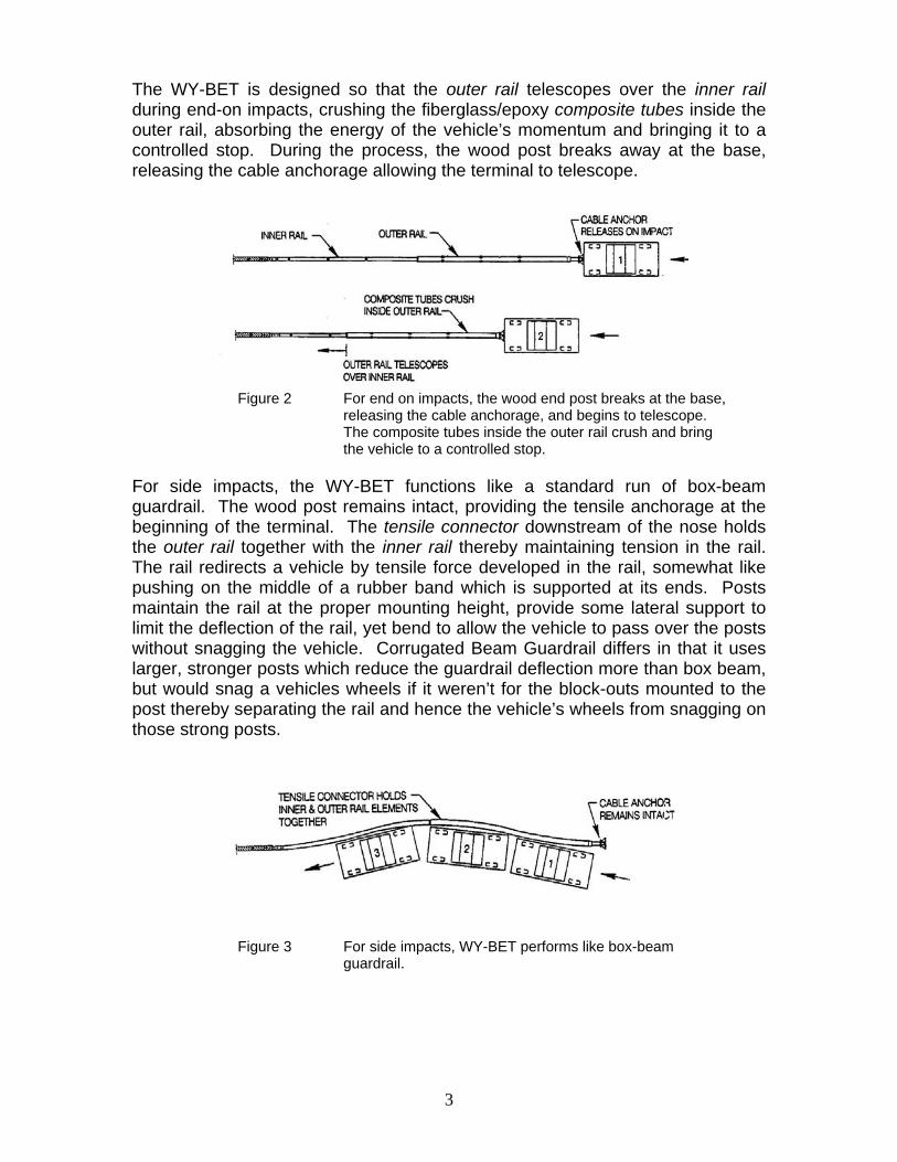
The WY-BET is designed so that the outer rail telescopes over the inner rail during end-on impacts, crushing the fiberglass/epoxy composite tubes inside the outer rail, absorbing the energy of the vehicle’s momentum and bringing it to a controlled stop. During the process, the wood post breaks away at the base, releasing the cable anchorage allowing the terminal to telescope.
Figure 2 For end on impacts, the wood end post breaks at the base, releasing the cable anchorage, and begins to telescope. The composite tubes inside the outer rail crush and bring the vehicle to a controlled stop. For side impacts, the WY-BET functions like a standard run of box-beam guardrail. The wood post remains intact, providing the tensile anchorage at the beginning of the terminal. The tensile connector downstream of the nose holds the outer rail together with the inner rail thereby maintaining tension in the rail. The rail redirects a vehicle by tensile force developed in the rail, somewhat like pushing on the middle of a rubber band which is supported at its ends. Posts maintain the rail at the proper mounting height, provide some lateral support to limit the deflection of the rail, yet bend to allow the vehicle to pass over the posts without snagging the vehicle. Corrugated Beam Guardrail differs in that it uses larger, stronger posts which reduce the guardrail deflection more than box beam, but would snag a vehicles wheels if it weren’t for the block-outs mounted to the post thereby separating the rail and hence the vehicle’s wheels from snagging on those strong posts.
Figure 3 For side impacts, WY-BET performs like box-beam guardrail.
3
GRADING
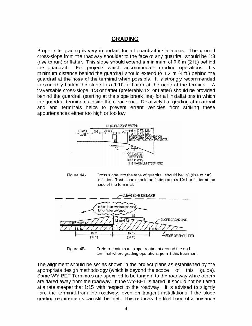
Proper site grading is very important for all guardrail installations. The ground cross-slope from the roadway shoulder to the face of any guardrail should be 1:8 (rise to run) or flatter. This slope should extend a minimum of 0.6 m (2 ft.) behind the guardrail. For projects which accommodate grading operations, this minimum distance behind the guardrail should extend to 1.2 m (4 ft.) behind the guardrail at the nose of the terminal when possible. It is strongly recommended to smoothly flatten the slope to a 1:10 or flatter at the nose of the terminal. A traversable cross-slope, 1:3 or flatter (preferably 1:4 or flatter) should be provided behind the guardrail (starting at the slope break line) for all installations in which the guardrail terminates inside the clear zone. Relatively flat grading at guardrail and end terminals helps to prevent errant vehicles from striking these appurtenances either too high or too low.
Figure 4A- Cross slope into the face of guardrail should be 1:8 (rise to run) or flatter. That slope should be flattened to a 10:1 or flatter at the nose of the terminal.
Figure 4B- Preferred minimum slope treatment around the end terminal where grading operations permit this treatment. The alignment should be set as shown in the project plans as established by the appropriate design methodology (which is beyond the scope of this guide). Some WY-BET Terminals are specified to be tangent to the roadway while others are flared away from the roadway. If the WY-BET is flared, it should not be flared at a rate steeper that 1:15 with respect to the roadway. It is advised to slightly flare the terminal from the roadway, even on tangent installations if the slope grading requirements can still be met. This reduces the likelihood of a nuisance
4
impact, such as a snowplow clearing snow from the shoulder of the road. It is desirable to have the nose of the terminal set behind the line delineators when possible. Whether flared or not flared, the entire length of the WY-BET must be installed straight and true to allow it to properly telescope when needed.
PRIOR TO INSTALLATION
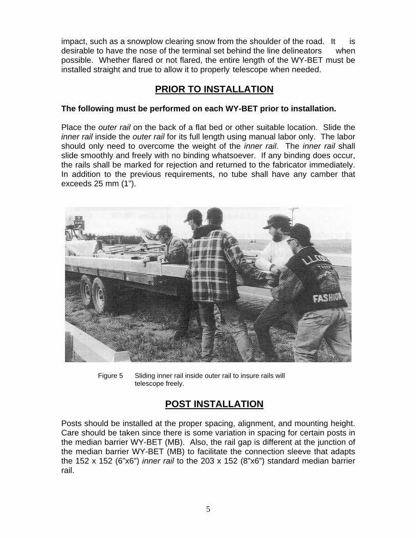
The following must be performed on each WY-BET prior to installation. Place the outer rail on the back of a flat bed or other suitable location. Slide the inner rail inside the outer rail for its full length using manual labor only. The labor should only need to overcome the weight of the inner rail. The inner rail shall slide smoothly and freely with no binding whatsoever. If any binding does occur, the rails shall be marked for rejection and returned to the fabricator immediately. In addition to the previous requirements, no tube shall have any camber that exceeds 25 mm (1”).
Figure 5 Sliding inner rail inside outer rail to insure rails will telescope freely.
POST INSTALLATION
Posts should be installed at the proper spacing, alignment, and mounting height. Care should be taken since there is some variation in spacing for certain posts in the median barrier WY-BET (MB). Also, the rail gap is different at the junction of the median barrier WY-BET (MB) to facilitate the connection sleeve that adapts the 152 x 152 (6”x6”) inner rail to the 203 x 152 (8”x6”) standard median barrier rail.
5
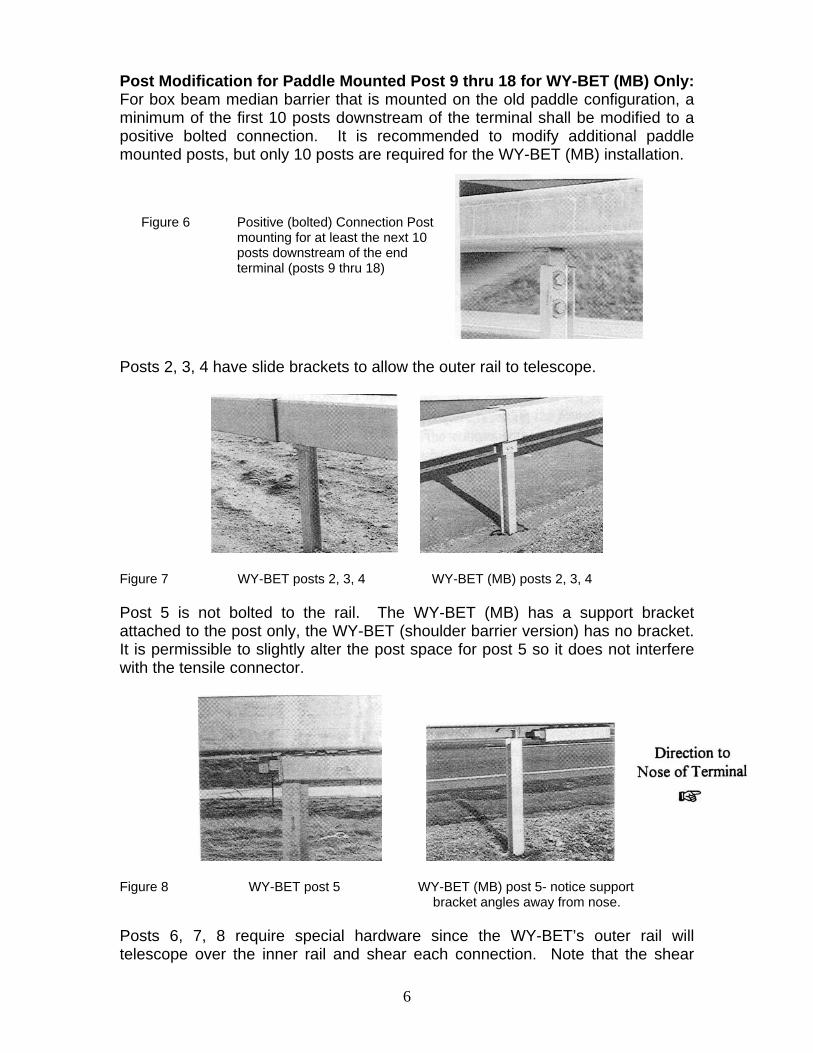
Post Modification for Paddle Mounted Post 9 thru 18 for WY-BET (MB) Only: For box beam median barrier that is mounted on the old paddle configuration, a minimum of the first 10 posts downstream of the terminal shall be modified to a positive bolted connection. It is recommended to modify additional paddle mounted posts, but only 10 posts are required for the WY-BET (MB) installation.
Figure 6 Positive (bolted) Connection Post mounting for at least the next 10 posts downstream of the end terminal (posts 9 thru 18)
Posts 2, 3, 4 have slide brackets to allow the outer rail to telescope.
Figure 7 WY-BET posts 2, 3, 4 WY-BET (MB) posts 2, 3, 4 Post 5 is not bolted to the rail. The WY-BET (MB) has a support bracket attached to the post only, the WY-BET (shoulder barrier version) has no bracket. It is permissible to slightly alter the post space for post 5 so it does not interfere with the tensile connector.
Figure 8 WY-BET post 5 WY-BET (MB) post 5- notice support bracket angles away from nose. Posts 6, 7, 8 require special hardware since the WY-BET’s outer rail will telescope over the inner rail and shear each connection. Note that the shear
6
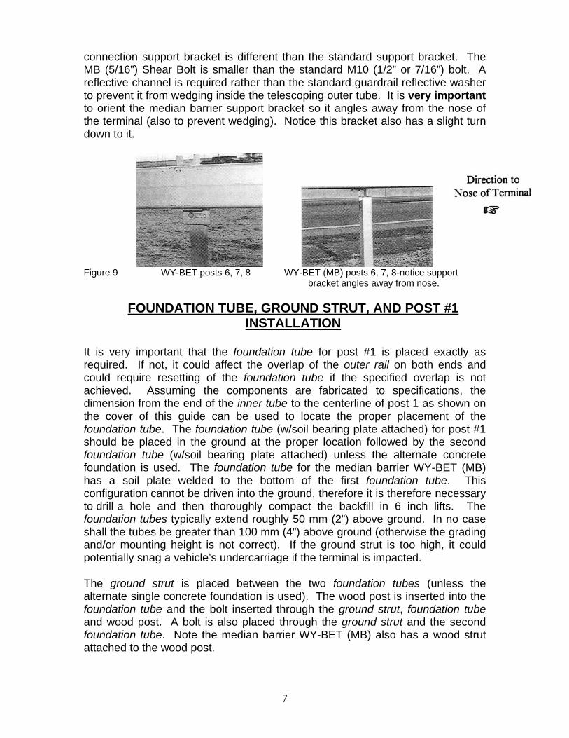
connection support bracket is different than the standard support bracket. The MB (5/16”) Shear Bolt is smaller than the standard M10 (1/2” or 7/16”) bolt. A reflective channel is required rather than the standard guardrail reflective washer to prevent it from wedging inside the telescoping outer tube. It is very important to orient the median barrier support bracket so it angles away from the nose of the terminal (also to prevent wedging). Notice this bracket also has a slight turn down to it.
Figure 9 WY-BET posts 6, 7, 8 WY-BET (MB) posts 6, 7, 8-notice support bracket angles away from nose.
FOUNDATION TUBE, GROUND STRUT, AND POST #1 INSTALLATION
It is very important that the foundation tube for post #1 is placed exactly as required. If not, it could affect the overlap of the outer rail on both ends and could require resetting of the foundation tube if the specified overlap is not achieved. Assuming the components are fabricated to specifications, the dimension from the end of the inner tube to the centerline of post 1 as shown on the cover of this guide can be used to locate the proper placement of the foundation tube. The foundation tube (w/soil bearing plate attached) for post #1 should be placed in the ground at the proper location followed by the second foundation tube (w/soil bearing plate attached) unless the alternate concrete foundation is used. The foundation tube for the median barrier WY-BET (MB) has a soil plate welded to the bottom of the first foundation tube. This configuration cannot be driven into the ground, therefore it is therefore necessary to drill a hole and then thoroughly compact the backfill in 6 inch lifts. The foundation tubes typically extend roughly 50 mm (2”) above ground. In no case shall the tubes be greater than 100 mm (4”) above ground (otherwise the grading and/or mounting height is not correct). If the ground strut is too high, it could potentially snag a vehicle’s undercarriage if the terminal is impacted. The ground strut is placed between the two foundation tubes (unless the alternate single concrete foundation is used). The wood post is inserted into the foundation tube and the bolt inserted through the ground strut, foundation tube and wood post. A bolt is also placed through the ground strut and the second foundation tube. Note the median barrier WY-BET (MB) also has a wood strut attached to the wood post.
7
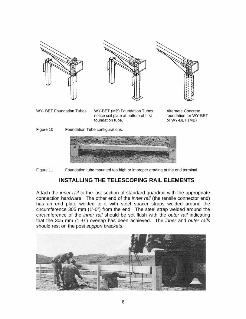
WY- BET Foundation Tubes WY-BET (MB) Foundation Tubes Alternate Concrete notice soil plate at bottom of first foundation for WY-BET foundation tube. or WY-BET (MB)
Figure 10 Foundation Tube configurations.
Figure 11 Foundation tube mounted too high or improper grading at the end terminal.
INSTALLING THE TELESCOPING RAIL ELEMENTS
Attach the inner rail to the last section of standard guardrail with the appropriate connection hardware. The other end of the inner rail (the tensile connector end) has an end plate welded to it with steel spacer straps welded around the circumference 305 mm (1’-0”) from the end. The steel strap welded around the circumference of the inner rail should be set flush with the outer rail indicating that the 305 mm (1’-0”) overlap has been achieved. The inner and outer rails should rest on the post support brackets.
8
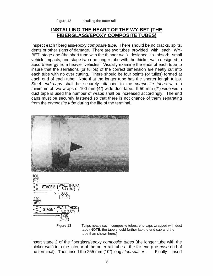
Figure 12 Installing the outer rail.
INSTALLING THE HEART OF THE WY-BET (THE FIBERGLASS/EPOXY COMPOSITE TUBES)
Inspect each fiberglass/epoxy composite tube. There should be no cracks, splits, dents or other signs of damage. There are two tubes provided with each WY-BET, stage one (the short tube with the thinner wall) designed to absorb small vehicle impacts, and stage two (the longer tube with the thicker wall) designed to absorb energy from heavier vehicles. Visually examine the ends of each tube to insure that the serrations (or tulips) of the correct dimension are neatly cut into each tube with no over cutting. There should be four points (or tulips) formed at each end of each tube. Note that the longer tube has the shorter length tulips. Steel end caps shall be securely attached to the composite tubes with a minimum of two wraps of 100 mm (4”) wide duct tape. If 50 mm (2”) wide width duct tape is used the number of wraps shall be increased accordingly. The end caps must be securely fastened so that there is not chance of them separating from the composite tube during the life of the terminal.
Figure 13 Tulips neatly cut in composite tubes, end caps wrapped with duct
tape (NOTE: the tape should further lap the end cap and the tube than shown here.)
Insert stage 2 of the fiberglass/epoxy composite tubes (the longer tube with the thicker wall) into the interior of the outer rail tube at the far end (the nose end of the terminal). Then insert the 255 mm (10”) long steel spacer. Finally insert
9
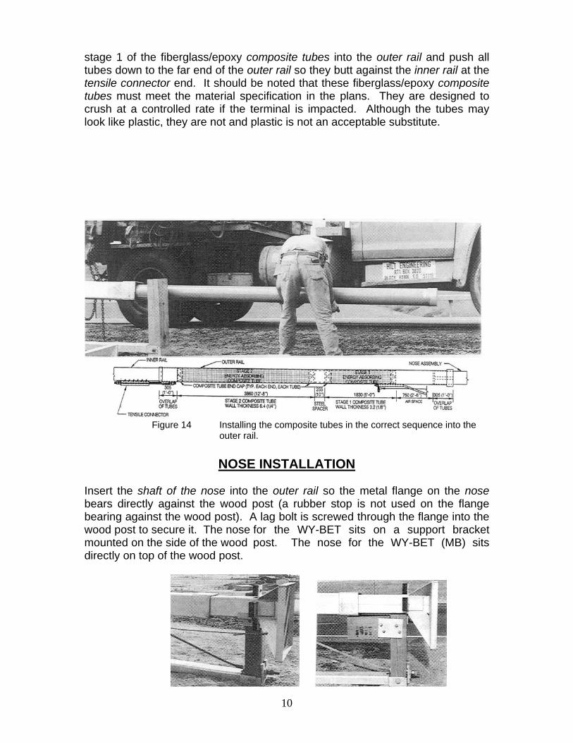
stage 1 of the fiberglass/epoxy composite tubes into the outer rail and push all tubes down to the far end of the outer rail so they butt against the inner rail at the tensile connector end. It should be noted that these fiberglass/epoxy composite tubes must meet the material specification in the plans. They are designed to crush at a controlled rate if the terminal is impacted. Although the tubes may look like plastic, they are not and plastic is not an acceptable substitute.
Figure 14 Installing the composite tubes in the correct sequence into the outer rail.
NOSE INSTALLATION Insert the shaft of the nose into the outer rail so the metal flange on the nose bears directly against the wood post (a rubber stop is not used on the flange bearing against the wood post). A lag bolt is screwed through the flange into the wood post to secure it. The nose for the WY-BET sits on a support bracket mounted on the side of the wood post. The nose for the WY-BET (MB) sits directly on top of the wood post.
10
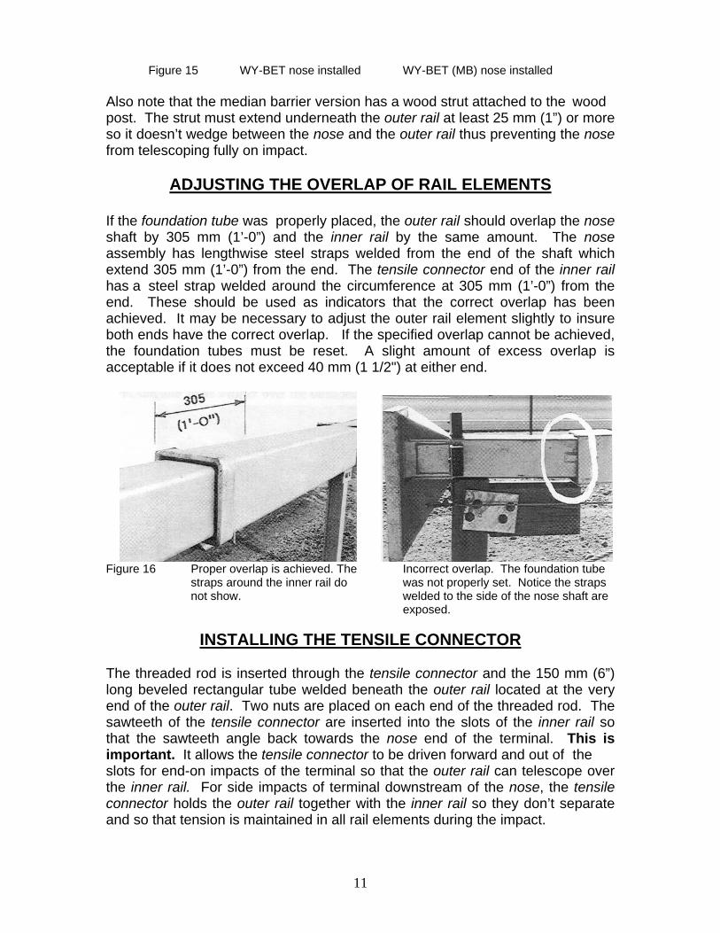
Figure 15 WY-BET nose installed WY-BET (MB) nose installed Also note that the median barrier version has a wood strut attached to the wood post. The strut must extend underneath the outer rail at least 25 mm (1”) or more so it doesn’t wedge between the nose and the outer rail thus preventing the nose from telescoping fully on impact.
ADJUSTING THE OVERLAP OF RAIL ELEMENTS
If the foundation tube was properly placed, the outer rail should overlap the nose shaft by 305 mm (1’-0”) and the inner rail by the same amount. The nose assembly has lengthwise steel straps welded from the end of the shaft which extend 305 mm (1’-0”) from the end. The tensile connector end of the inner rail has a steel strap welded around the circumference at 305 mm (1’-0”) from the end. These should be used as indicators that the correct overlap has been achieved. It may be necessary to adjust the outer rail element slightly to insure both ends have the correct overlap. If the specified overlap cannot be achieved, the foundation tubes must be reset. A slight amount of excess overlap is acceptable if it does not exceed 40 mm (1 1/2") at either end.
Figure 16 Proper overlap is achieved. The Incorrect overlap. The foundation tube straps around the inner rail do was not properly set. Notice the straps not show. welded to the side of the nose shaft are exposed.
INSTALLING THE TENSILE CONNECTOR
The threaded rod is inserted through the tensile connector and the 150 mm (6”) long beveled rectangular tube welded beneath the outer rail located at the very end of the outer rail. Two nuts are placed on each end of the threaded rod. The sawteeth of the tensile connector are inserted into the slots of the inner rail so that the sawteeth angle back towards the nose end of the terminal. This is important. It allows the tensile connector to be driven forward and out of the slots for end-on impacts of the terminal so that the outer rail can telescope over the inner rail. For side impacts of terminal downstream of the nose, the tensile connector holds the outer rail together with the inner rail so they don’t separate and so that tension is maintained in all rail elements during the impact.
11
With the tensile connector properly inserted into the slots of the inner rail, hand tighten only the first nut on each end of the threaded rod. The second nut will be tightened once the system has been tensioned. Make sure the minimum overlap at each end of the outer rail is maintained.
Figure 17 The tensile connector is inserted into the slots of the inner rail with the sawteeth of the connector angling back towards the nose of the terminal.
INSTALLING THE CABLE ANCHOR
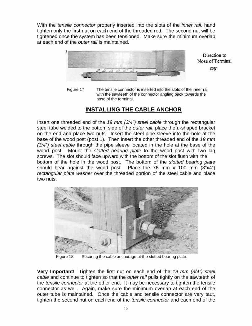
Insert one threaded end of the 19 mm (3/4”) steel cable through the rectangular steel tube welded to the bottom side of the outer rail, place the u-shaped bracket on the end and place two nuts. Insert the steel pipe sleeve into the hole at the base of the wood post (post 1). Then insert the other threaded end of the 19 mm (3/4”) steel cable through the pipe sleeve located in the hole at the base of the wood post. Mount the slotted bearing plate to the wood post with two lag screws. The slot should face upward with the bottom of the slot flush with the bottom of the hole in the wood post. The bottom of the slotted bearing plate should bear against the wood post. Place the 76 mm x 100 mm (3”x4”) rectangular plate washer over the threaded portion of the steel cable and place two nuts.
Figure 18 Securing the cable anchorage at the slotted bearing plate.
Very Important! Tighten the first nut on each end of the 19 mm (3/4”) steel cable and continue to tighten so that the outer rail pulls tightly on the sawteeth of the tensile connector at the other end. It may be necessary to tighten the tensile connector as well. Again, make sure the minimum overlap at each end of the outer tube is maintained. Once the cable and tensile connector are very taut, tighten the second nut on each end of the tensile connector and each end of the
12
19 mm (3/4”) steel cable. The tension should be rechecked after the system has been installed for a reasonable period of time (for construction contracts this should be done just prior to final inspection). Should slack occur in the system, it is possible that the tensile connector could fall out of the slots, thus rendering it useless. This is an item which should be checked by maintenance forces periodically.
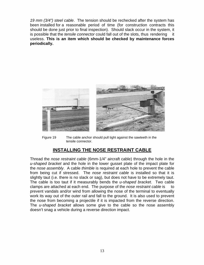
Figure 19 The cable anchor should pull tight against the sawteeth in the tensile connector.
INSTALLING THE NOSE RESTRAINT CABLE
Thread the nose restraint cable (6mm-1/4” aircraft cable) through the hole in the u-shaped bracket and the hole in the lower gusset plate of the impact plate for the nose assembly. A cable thimble is required at each hole to prevent the cable from being cut if stressed. The nose restraint cable is installed so that it is slightly taut (i.e. there is no slack or sag), but does not have to be extremely taut. The cable is too taut if it measurably bends the u-shaped bracket. Two cable clamps are attached at each end. The purpose of the nose restraint cable is to prevent vandals and/or wind from allowing the nose of the terminal to eventually work its way out of the outer rail and fall to the ground. It is also used to prevent the nose from becoming a projectile if it is impacted from the reverse direction. The u-shaped bracket allows some give to the cable so the nose assembly doesn’t snag a vehicle during a reverse direction impact.
13
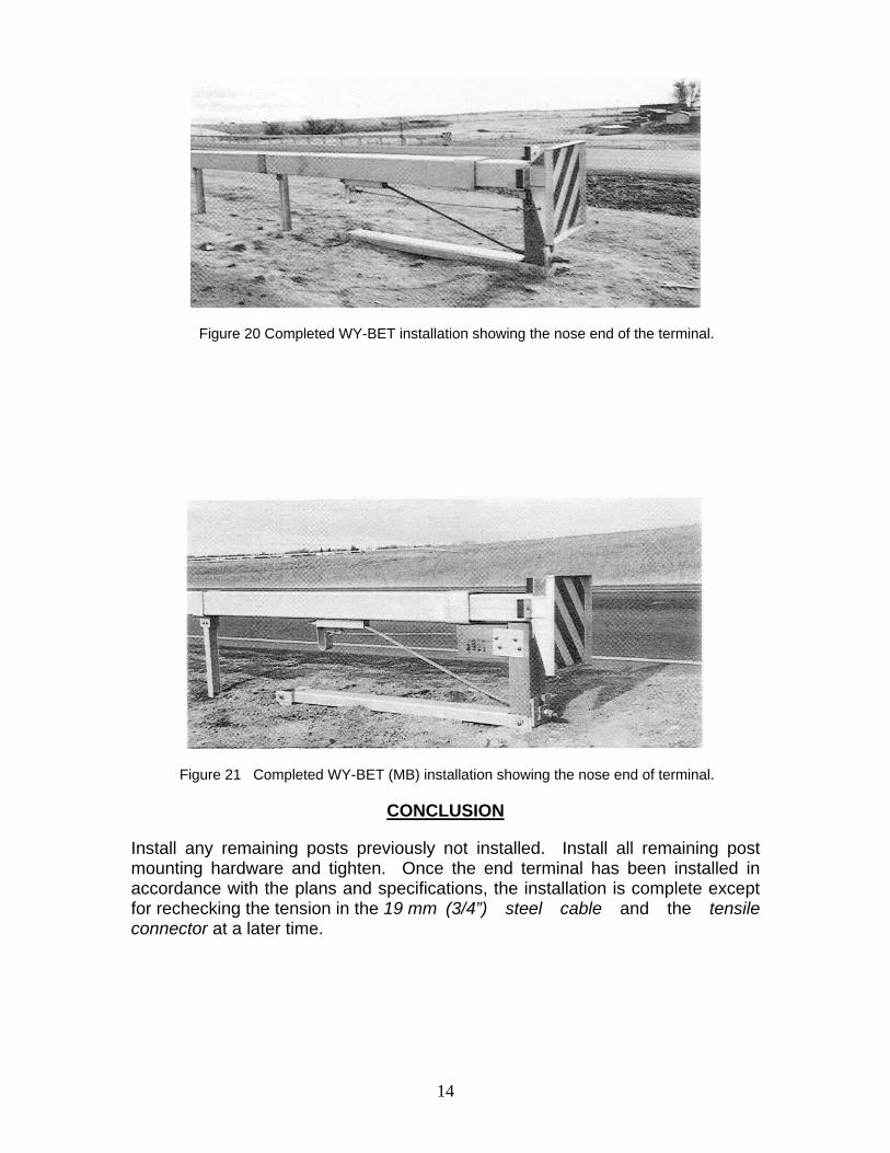
Figure 20 Completed WY-BET installation showing the nose end of the terminal.
Figure 21 Completed WY-BET (MB) installation showing the nose end of terminal.
CONCLUSION
Install any remaining posts previously not installed. Install all remaining post mounting hardware and tighten. Once the end terminal has been installed in accordance with the plans and specifications, the installation is complete except for rechecking the tension in the 19 mm (3/4”) steel cable and the tensile connector at a later time.
14