Embed Size (px)
DESCRIPTION
The Engineering Beauty of the Trebuchet
Citation preview
7/17/2019 The Engineering Beauty of the Trebuchet
http://slidepdf.com/reader/full/the-engineering-beauty-of-the-trebuchet 1/19
The Engineering Beauty of the Trebuchet
Desert Academy
313 Camino Alire
Santa Fe, NM 87501
Sections Prepared by
John Corff, MathematicsAlex Grunstein, Data Tables
Tory Passalaqua, History
Aaron Salman, Field Engineering
Stuart Pollock, Design and ConstructionJon Wheeler, History
Jessi Johnson, Editor
7/17/2019 The Engineering Beauty of the Trebuchet
http://slidepdf.com/reader/full/the-engineering-beauty-of-the-trebuchet 2/19
Introduction
The word “trebuchet” sounds like something you would find on a menu in
a fancy French restaurant. But this medieval weapon of mass destruction was
certainly not edible. Trebuchets were used to break through castle walls from
about 850-1350 C.E. Dead livestock or giant rocks were the usual ammunition,
but sometimes prisoners of war or especially annoying people were added to the
flying debris. Other launching devices similar to the trebuchet include the
catapult and the ballista.
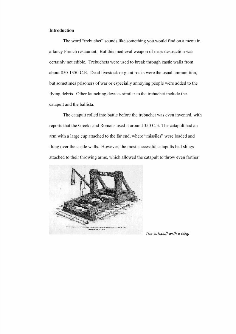
The catapult rolled into battle before the trebuchet was even invented, with
reports that the Greeks and Romans used it around 350 C.E. The catapult had an
arm with a large cup attached to the far end, where “missiles” were loaded and
flung over the castle walls. However, the most successful catapults had slings
attached to their throwing arms, which allowed the catapult to throw even farther.
The catapul with a sling t
7/17/2019 The Engineering Beauty of the Trebuchet
http://slidepdf.com/reader/full/the-engineering-beauty-of-the-trebuchet 3/19
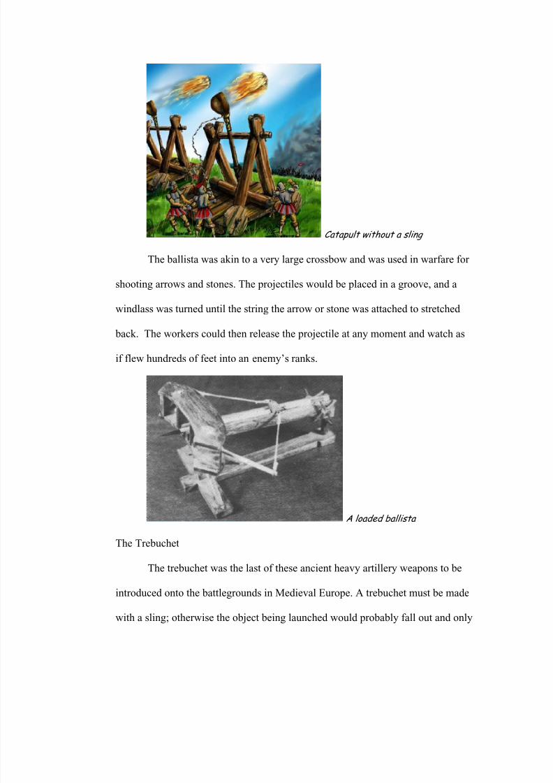
Catapult without a sling
The ballista was akin to a very large crossbow and was used in warfare for
shooting arrows and stones. The projectiles would be placed in a groove, and a
windlass was turned until the string the arrow or stone was attached to stretched
back. The workers could then release the projectile at any moment and watch as
if flew hundreds of feet into an enemy’s ranks.
A loaded ballista
The Trebuchet
The trebuchet was the last of these ancient heavy artillery weapons to be
introduced onto the battlegrounds in Medieval Europe. A trebuchet must be made
with a sling; otherwise the object being launched would probably fall out and only
7/17/2019 The Engineering Beauty of the Trebuchet
http://slidepdf.com/reader/full/the-engineering-beauty-of-the-trebuchet 4/19
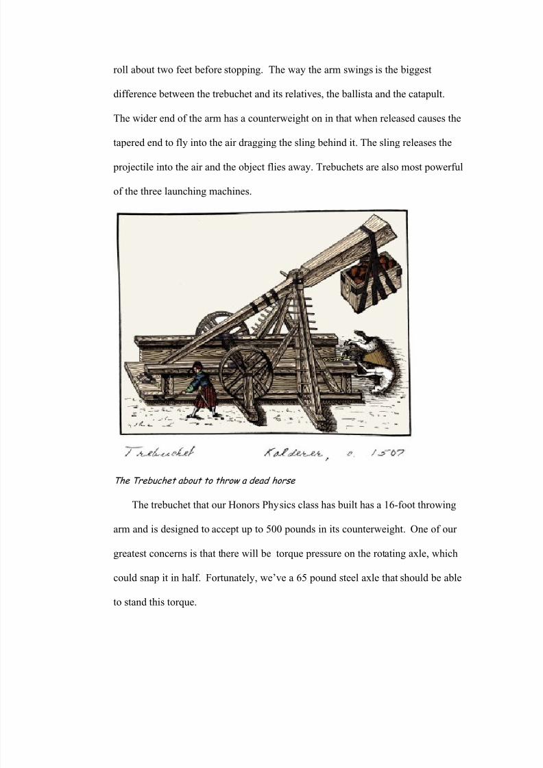
roll about two feet before stopping. The way the arm swings is the biggest
difference between the trebuchet and its relatives, the ballista and the catapult.
The wider end of the arm has a counterweight on in that when released causes the
tapered end to fly into the air dragging the sling behind it. The sling releases the
projectile into the air and the object flies away. Trebuchets are also most powerful
of the three launching machines.
The Trebuchet about to throw a dead horse
The trebuchet that our Honors Physics class has built has a 16-foot throwing
arm and is designed to accept up to 500 pounds in its counterweight. One of our
greatest concerns is that there will be torque pressure on the rotating axle, which
could snap it in half. Fortunately, we’ve a 65 pound steel axle that should be able
to stand this torque.
7/17/2019 The Engineering Beauty of the Trebuchet
http://slidepdf.com/reader/full/the-engineering-beauty-of-the-trebuchet 5/19
Of course, there’s always the fact that working with 500 pounds of
counterweight can always conjure up problems of its own.
Catapults come in a wide range of strengths and sizes, varying from a
small slingshot with a rubber band, to a 300-foot long aircraft launcher. During
the medieval ages, the catapult was used to attack fortresses and cities. Due to its
capability of launching a projectile such a long distance, it was also a very
effective defensive device. The three most common types of catapults that were
used during the medieval ages were the ballista, mangonel, and the trebuchet.
The ballista and the mangonel launch their projectiles from the torsion that
is created by twisting ropes. The design of the crossbow is very similar to that of
the ballista. The Roman mangonel design uses twisted ropes stretched
horizontally. A lever arm with a scoop at the end is inserted into the center of the
ropes. The projectile object is placed inside of the scoop while the lever arm is
pulled back against the force of the ropes. As the arm is released, it flings
forward and hits a wooden barrier thus causing the projectile to fly forward at the
enemy. It was a very effective design, capable of launching 50-60 pound stones
and destroying towers and castle walls. A particular flaw in the design of the
mangonel was that it wasted a large amount of energy upon impact with the
wooden barrier.
The French eventually introduced the near flawless design of the trebuchet
in the twelfth century. Unlike the previous catapults, the trebuchet relies on the
terrestrial gravitation from the counterweight to provide the force rather than
using torsion obtained from twisted cordage. The counterweight hangs at one end
7/17/2019 The Engineering Beauty of the Trebuchet
http://slidepdf.com/reader/full/the-engineering-beauty-of-the-trebuchet 6/19
of the beam, opposite of the sling. The sling is pulled towards the ground while
the counterweight is raised at the opposite end of the beam. As the sling is
released, the counterweight quickly falls towards the ground, flinging the
projectile and wasting much less energy than the designs of earlier catapults.
The trebuchet superseded the previous siege engines for many reasons. It
was far more efficient than any other design of its time and wasted very little
energy. The problem with earlier catapults was the difficulty that the operators
faced when the situation called for accuracy. The trebuchet was consistent and
easier to customize because the distance that the projectile would be thrown
depended on the weight of the counterpoise. The Roman mangonel could throw
50-60 pound stones but a large trebuchet was capable of throwing a 300 pound
projectile over 300 yards. During the years of the plague, armies would use the
trebuchet to launch diseased bodies over the enemy’s castle walls. People would
often dig large ditches around their castles to prevent besiegers from scaling
ladders to the walls. Besiegers would solve this problem by launching barrels
filled with dirt to fill the ditches, allowing them to pass over the ditch and access
the castle.
Math Simulations and Actual Data Collection
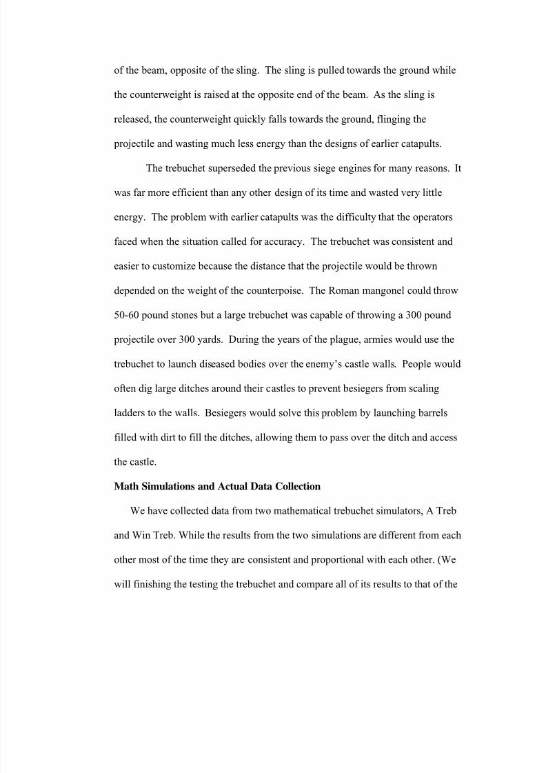
We have collected data from two mathematical trebuchet simulators, A Treb
and Win Treb. While the results from the two simulations are different from each
other most of the time they are consistent and proportional with each other. (We
will finishing the testing the trebuchet and compare all of its results to that of the
7/17/2019 The Engineering Beauty of the Trebuchet
http://slidepdf.com/reader/full/the-engineering-beauty-of-the-trebuchet 7/19
simulations as of April 15, 2004. The following charts reflect the partially
completed testing.)
Math Models Versus Actual Distance Thrown, 77.3 Kilogram Counterweight
0
5
10
15
20
25
30
35
40
0.20 0.30 0.40 0.50 0.60 0.70 0.80 0.90 1.00
Ball in Kilograms
Distance in Meters
Win Treb Range
A Treb Range
Actual
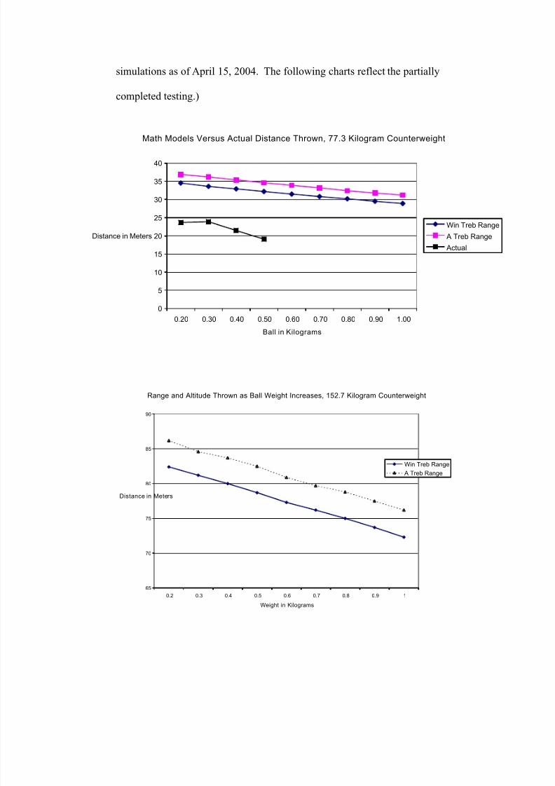
Range and Altitude Thrown as Ball Weight Increases, 152.7 Kilogram Counterweight
65
70
75
80
85
90
0.2 0.3 0.4 0.5 0.6 0.7 0.8 0.9 1
Weight in Kilograms
Distance in Meters
Win Treb Range
A Treb Range
7/17/2019 The Engineering Beauty of the Trebuchet
http://slidepdf.com/reader/full/the-engineering-beauty-of-the-trebuchet 8/19
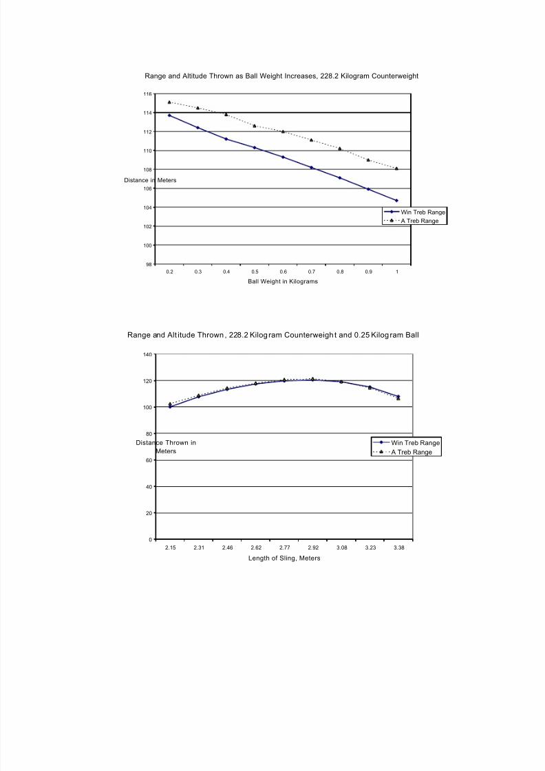
Range and Altitude Thrown as Ball Weight Increases, 228.2 Kilogram Counterweight
98
100
102
104
106
108
110
112
114
116
0.2 0.3 0.4 0.5 0.6 0.7 0.8 0.9 1
Ball Weight in Kilograms
Distance in Meters
Win Treb Range
A Treb Range
Range and Alt itude Thrown, 228.2 Kilog ram Counterweigh t and 0.25 Kilog ram Ball
0
20
40
60
80
100
120
140
2.15 2.31 2.46 2.62 2.77 2.92 3.08 3.23 3.38
Length of Sling, Meters
Distance Thrown in
Meters
Win Treb Range
A Treb Range
7/17/2019 The Engineering Beauty of the Trebuchet
http://slidepdf.com/reader/full/the-engineering-beauty-of-the-trebuchet 9/19
A number of simulations were done with the following variables and produced
elegant curves or straight lines in the resulting charts.
Length of the short side of the throwing arm
Length of the long side of the throwing arm
Length of the sling for throwing a water balloon
Height of the support columns
Distance from the throwing arm to the counterweight
Weight of the counterweight
Weight of the balloon being thrown
Both the Win Treb and A Treb simulations showed that the length of the sling
was a major variable that we could manipulate during construction of the
trebuchet. The A Treb simulation separately identified the angle of the release pin
as being a significant variable.
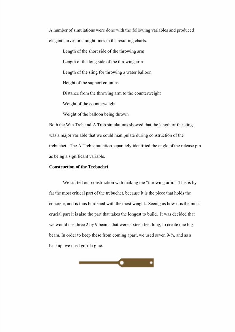
Construction of the Trebuchet
We started our construction with making the “throwing arm.” This is by
far the most critical part of the trebuchet, because it is the piece that holds the
concrete, and is thus burdened with the most weight. Seeing as how it is the most
crucial part it is also the part that takes the longest to build. It was decided that
we would use three 2 by 9 beams that were sixteen feet long, to create one big
beam. In order to keep these from coming apart, we used seven 9-½, and as a
backup, we used gorilla glue.
7/17/2019 The Engineering Beauty of the Trebuchet
http://slidepdf.com/reader/full/the-engineering-beauty-of-the-trebuchet 10/19
We used the same method of bolts and glue for the ten-foot side supports.
Our research told us that the perfect throwing arm would weigh nothing, but that
seemed impossible to us. We decided that like 60% of America, our beam needed
to loose weight, although the Atkins diet wouldn’t work for this particular cut
back. So, we decided to pull out the saw and cut off two sections on each side of
the beam. This resulted in the loss of 60 pounds. Not only does a lighter beam
have increased efficiency, but it’s a lot easier to carry as well.
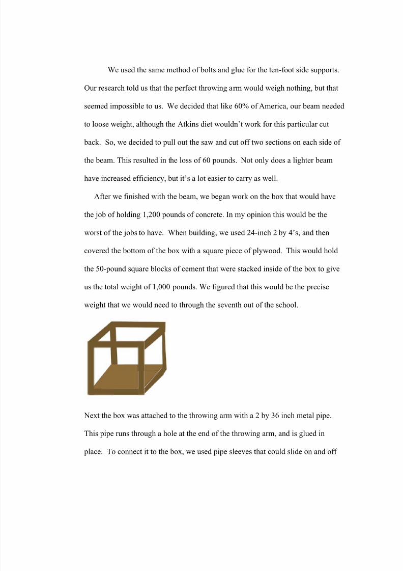
After we finished with the beam, we began work on the box that would have
the job of holding 1,200 pounds of concrete. In my opinion this would be the
worst of the jobs to have. When building, we used 24-inch 2 by 4’s, and then
covered the bottom of the box with a square piece of plywood. This would hold
the 50-pound square blocks of cement that were stacked inside of the box to give
us the total weight of 1,000 pounds. We figured that this would be the precise
weight that we would need to through the seventh out of the school.
Next the box was attached to the throwing arm with a 2 by 36 inch metal pipe.
This pipe runs through a hole at the end of the throwing arm, and is glued in
place. To connect it to the box, we used pipe sleeves that could slide on and off
7/17/2019 The Engineering Beauty of the Trebuchet
http://slidepdf.com/reader/full/the-engineering-beauty-of-the-trebuchet 11/19
the pipe. Through these pipe sleeves we ran ½ inch cables that were then tied
around the box. This design is much related to a harness that you might put on a
dog.
For the base of the trebuchet we used sixteen 2 by 4’s that were eight feet
long, and made two boxes that would then be able to fit together to make 16 feet.
We decided that the width of the base would be 30 inches, because this would be
wide enough to support the beam. After the base was constructed, the top was
covered with plywood so that our sling would be able to slide off of it during
launches.
While constructing our fabulous marvel of technology, there were a few
things that we had to keep in mind. Altogether, our wondrous piece of work
weighs about 1,700 pounds, so it would be preposterous to dream of trying to
have seven teenagers lift it by themselves. The trebuchet had to be able to break
down into separate pieces so that each lighter section could be carted to different
places, and then reconstructed at its destination. Also, the trebuchet would be
holding 1,000 pounds of weight, so the supports and beams had to be extremely
strong. With these ideas in mind, many of our designs had to change. For
example, we constructed the base so that it could break into two pieces. The
throwing arm is able to slide on and off the axle, both side supports can be moved
separately, and the bucket can slide off the axle that it’s on. This will be crucial
in the process of moving it.
The most precarious part of the trebuchet was the pivoting axle of the arm.
This runs through both side supports and the throwing arm. When designing, we
7/17/2019 The Engineering Beauty of the Trebuchet
http://slidepdf.com/reader/full/the-engineering-beauty-of-the-trebuchet 12/19
were trying to figure out what size axle would be big enough and strong enough
to hold 1,300 pounds. It was thought that a 2-inch thick pipe would be able to
hold the weight. However, after we ran some calculations, we discovered that the
weight immobile would weigh about 1,300 pounds; but that same weight in
movement would create about 3 tons of weight. This led us to one conclusion:
“we’re going to need a thicker pipe.” Little did we know the pipe that our teacher
ordered was 4 inches thick and weighed about 100 pounds. So once again our
previous ideas were forced to change.
We slid the axle through two holes that were cut into the side supports,
and, because we knew that the trebuchet would be more efficient if the axle
stayed still, we wanted to glued one end of it into one of the support beams, but
for the sake of the poor people who would have to carry it we didn’t glue it in
place. Next, we made a metal sleeve that fit perfectly over the axle, allowing both
sleeve and throwing arm to rotate around the axle during launch. When we used
the trebuchet we put grease around the axle to minimize friction.
When you have a structure that is close to 25 ft tall it is pretty hard to take
just one step back to look at the bigger picture so, we looked at a miniature model
of our trebuchet; we noticed that it swayed from side to side a lot. Because of
this, we decided to add side braces that resemble the flying buttresses in older
buildings. Along with the side braces, there are diagonal braces running from the
vertical support to the base. They are critical in making sure that the swinging
weight doesn’t make the vertical supports fall over.
7/17/2019 The Engineering Beauty of the Trebuchet
http://slidepdf.com/reader/full/the-engineering-beauty-of-the-trebuchet 13/19
Many trebuchets at the end of the throwing arm have one release pin,
which is straight out, however our research told us that it is good to have more
than one pin, all at different angles. The way that the release pin works is when
the arm begins to swing the sling is beginning to be thrown, however once it the
end of the arm reaches a certain point the inertia pulls the loop off the pin. With
different angled pins the release point will change. So one pin will make it fire
more vertical than horizontal, whereas the other one will do the opposite.
Using one of our simulation programs we determined that the perfect
launch item would weigh 2 pounds. Unfortunately it is very hard to find a 2-
pound metal ball, so we have decided to improvise. The only thing we could find
where we could change the weight freely was a water balloon. The problem with
water balloons is that they change shape as they are being flung. This makes them
much less aerodynamic, so we decided to freeze them so that they would keep
their shape. While we were thinking about the freeze processes, we decided that it
would be helpful if we could somehow get the balloon to leave a trail in the air.
The solution that we came up will was liquid nitrogen. If we dipped the balloons
in the nitrogen right before we shot them, they should hypothetically leave a trail.
Two Construction Flaws
The trebuchet was built in modular sections. The base was built as one
module and the support columns built as a second module. The throwing arm was
built as a third module while the counterweight box was built as a forth module. A
major construction flow resulted in the third and fourth modules.
The support axle was built to have a minimum length in order to reduce
the amount of stress on placed on it from the throwing arm and counterweight.
7/17/2019 The Engineering Beauty of the Trebuchet
http://slidepdf.com/reader/full/the-engineering-beauty-of-the-trebuchet 14/19
The concern was that the axle could bend under the combined weight if it was
very long. The axle had an overall length of 24 inches after construction and an
effective gap of 15 inches after being placed on the two support columns.
The box for the concrete blocks was constructed to be 24 inches on a side
in order to hold 40 pound concrete blocks that measured 12 inches by 12 inches
on a side. The concrete blocks then were to be placed in two parallel rows and
easily added or removed. It was only when the modules were being assembled
that we realized that the 24 inch wide box would not be able to swing freely
between the 15 inch gap of the two support columns.
The two support columns therefore were modified to spread on diagonals
rather than remain vertical. The box was rebuilt of steel with three high density
concrete blocks used for the counterweights. Each high density concrete block
weighs 166 pounds and requires two people to lift into position—difficult but
possible. The result was a box that was 13 inches on a side and gap of 24 inches
at the base of the support columns.
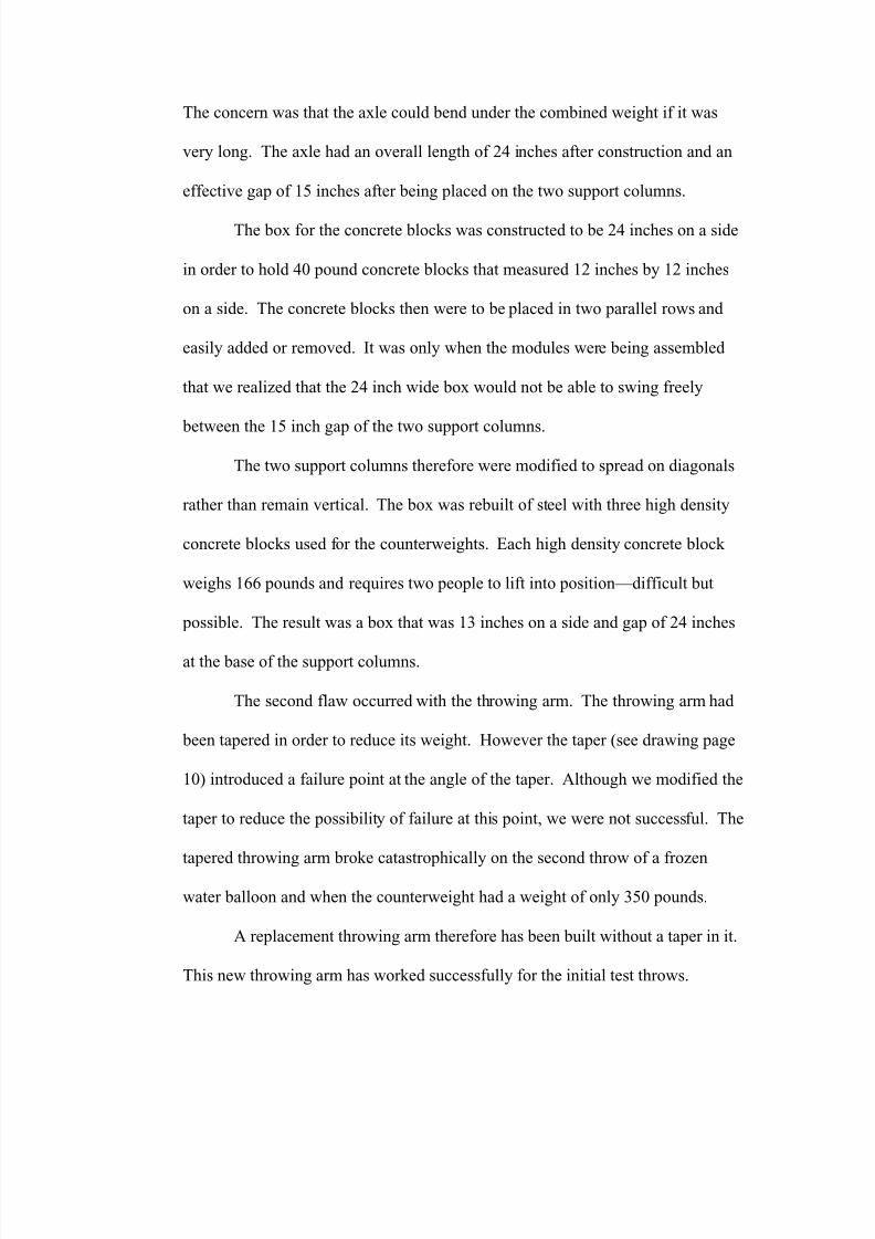
The second flaw occurred with the throwing arm. The throwing arm had
been tapered in order to reduce its weight. However the taper (see drawing page
10) introduced a failure point at the angle of the taper. Although we modified the
taper to reduce the possibility of failure at this point, we were not successful. The
tapered throwing arm broke catastrophically on the second throw of a frozen
water balloon and when the counterweight had a weight of only 350 pounds.
A replacement throwing arm therefore has been built without a taper in it.
This new throwing arm has worked successfully for the initial test throws.
7/17/2019 The Engineering Beauty of the Trebuchet
http://slidepdf.com/reader/full/the-engineering-beauty-of-the-trebuchet 15/19
However the arm now weighs 136 pounds. A significant amount of weight in the
counterweight now must be used to overcome the weight of the arm rather than
contributing energy to the water balloon being thrown.
Results
A functional trebuchet has now been made with significant engineering
lessons in the construction of a massive machine. A careful set of complete
drawings should have been used instead of proceeding with separate modules.
However only experience could tell us if the tapered beam would withstand the
anticipated load.
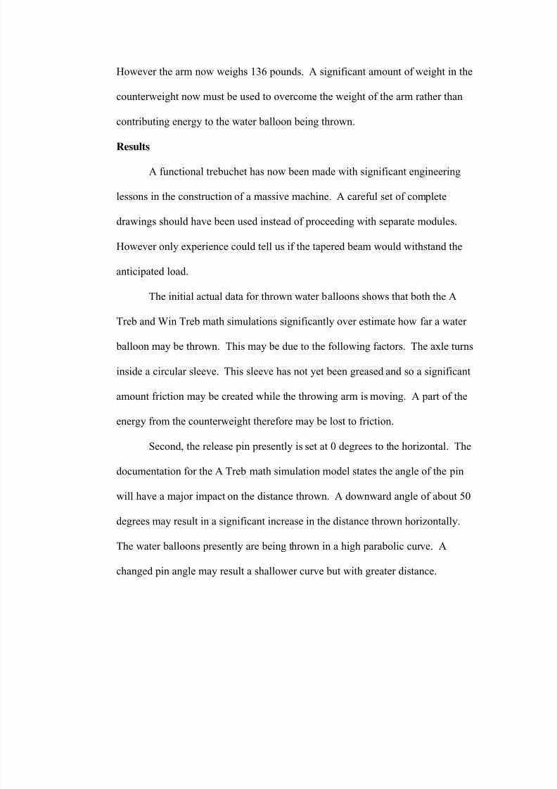
The initial actual data for thrown water balloons shows that both the A
Treb and Win Treb math simulations significantly over estimate how far a water
balloon may be thrown. This may be due to the following factors. The axle turns
inside a circular sleeve. This sleeve has not yet been greased and so a significant
amount friction may be created while the throwing arm is moving. A part of the
energy from the counterweight therefore may be lost to friction.
Second, the release pin presently is set at 0 degrees to the horizontal. The
documentation for the A Treb math simulation model states the angle of the pin
will have a major impact on the distance thrown. A downward angle of about 50
degrees may result in a significant increase in the distance thrown horizontally.
The water balloons presently are being thrown in a high parabolic curve. A
changed pin angle may result a shallower curve but with greater distance.
7/17/2019 The Engineering Beauty of the Trebuchet
http://slidepdf.com/reader/full/the-engineering-beauty-of-the-trebuchet 16/19
Trebuchet Mathematics
Newton’s second law of motion states that force equals mass times
acceleration. For the trebuchet, because the forces operate on curves, the equation
is a little different. The equation for the acceleration is: F * r = Ia and the
acceleration is actually angular acceleration, to account for the curves. The I in
the equation is the moment of inertia or. I=Emr^2. The moment of inertia is
conceptually found by cutting the acceleration of the mass into all of its infinite
moments or points and find the mass of each point times the distance from the
center squared then add each of the infinite accelerations to find the inertia, hence
I=∑*m*r^2.
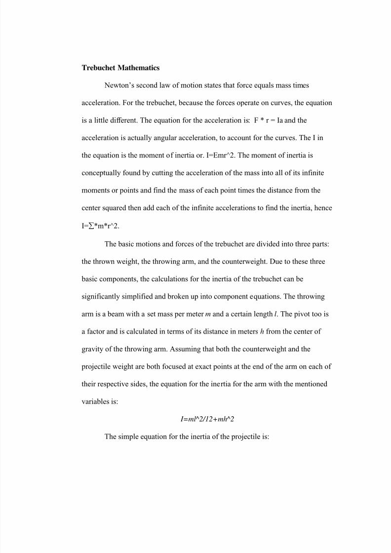
The basic motions and forces of the trebuchet are divided into three parts:
the thrown weight, the throwing arm, and the counterweight. Due to these three
basic components, the calculations for the inertia of the trebuchet can be
significantly simplified and broken up into component equations. The throwing
arm is a beam with a set mass per meter m and a certain length l. The pivot too is
a factor and is calculated in terms of its distance in meters h from the center of
gravity of the throwing arm. Assuming that both the counterweight and the
projectile weight are both focused at exact points at the end of the arm on each of
their respective sides, the equation for the inertia for the arm with the mentioned
variables is:
I=ml^2/12+mh^2
The simple equation for the inertia of the projectile is:
7/17/2019 The Engineering Beauty of the Trebuchet
http://slidepdf.com/reader/full/the-engineering-beauty-of-the-trebuchet 17/19
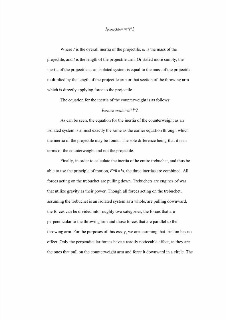
I projectile=m*l^2
Where I is the overall inertia of the projectile, m is the mass of the
projectile, and l is the length of the projectile arm. Or stated more simply, the
inertia of the projectile as an isolated system is equal to the mass of the projectile
multiplied by the length of the projectile arm or that section of the throwing arm
which is directly applying force to the projectile.
The equation for the inertia of the counterweight is as follows:
I counterweight
=m*l^2
As can be seen, the equation for the inertia of the counterweight as an
isolated system is almost exactly the same as the earlier equation through which
the inertia of the projectile may be found. The sole difference being that it is in
terms of the counterweight and not the projectile.
Finally, in order to calculate the inertia of he entire trebuchet, and thus be
able to use the principle of motion, F*R=Ia, the three inertias are combined. All
forces acting on the trebuchet are pulling down. Trebuchets are engines of war
that utilize gravity as their power. Though all forces acting on the trebuchet,
assuming the trebuchet is an isolated system as a whole, are pulling downward,
the forces can be divided into roughly two categories, the forces that are
perpendicular to the throwing arm and those forces that are parallel to the
throwing arm. For the purposes of this essay, we are assuming that friction has no
effect. Only the perpendicular forces have a readily noticeable effect, as they are
the ones that pull on the counterweight arm and force it downward in a circle. The
7/17/2019 The Engineering Beauty of the Trebuchet
http://slidepdf.com/reader/full/the-engineering-beauty-of-the-trebuchet 18/19
parallel forces are attempting to push the trebuchet over lengthwise, and as such,
are not of any use in throwing the projectile. The fulcrum of the trebuchet serves
to transmit all of these forces throughout the trebuchet, countering the parallel
forces and transferring the perpendicular forces, rather like a force filter.
The equation for the perpendicular force is:
F⊥=Fsinθ
Where angle θ is the angle of the fulcrum to the counterweight arm.
The strength of the perpendicular force depends on the distance from the
point of application to the center of the fulcrum, or the radius of the circle
described by the trebuchet arm. Thus, the perpendicular force utilizes torque to
multiply the force of the counterweight.
In the original acceleration equation, F*R may now be replaced by
F*r*sinθ or F ⊥*r. Thus the acceleration of the trebuchet is directly related to not
only the mass of the counterweight and the projectile, but also to the angle of the
throwing arm in terms of the fulcrum. Once the angle gets to 90, the force peaks
and all angles there after have increasingly less force, because at 90 degrees the
counterweight is exactly perpendicular with the ground and gravity will no longer
be supplying the force at any larger angle. This is because at 90 degrees the
counterweight is as close to the ground as it is going to get or as close as gravity is
trying to make it.
The final and much simpler equation for acceleration is:
F*r=F*r*sinθ
7/17/2019 The Engineering Beauty of the Trebuchet
http://slidepdf.com/reader/full/the-engineering-beauty-of-the-trebuchet 19/19
References
Euclid, “The Elements”
Newton, Isaac, “The Principia”
Siano, “Will it Break”
Sholtz, “A Treb Simulation Software”
Siano, “Win Treb Simulation Software”
Sir Ralph-Payne Gallway “The Projectile Throwing Engines of the Ancients”,
1907.


![Trebuchet versus Flinger: Millennial mechanics and bio ... · Harter - Trebuchet 3 1. Introduction The trebuchet or ingenium [1,2] was a super-catapult invented in China about 400BC](https://img.pdfslide.us/doc/110x75/5c61d37c09d3f2eb708b5d80/trebuchet-versus-flinger-millennial-mechanics-and-bio-harter-trebuchet.jpg)