Embed Size (px)
Citation preview
+t)/7'N~THE ELECTRO-ANALOGUE,
AN APPARATUS FOR STUDYING REGULATING SYSTEMS
1. COMPONENTS AND FUNCTIONS
MARCH 1951 257
by J. M. L. JANSSEN and L. ENSING. 621-52 :621.3.012.8 :53.072.13
-------
Mtuhematicai oper ations such as adding, sulnructing, multiplying, dividing, differentiatingand integrating can be carried out with the aid of electrical circuit elements. On this principle it ispossible to construct el e c tri c al m ode I s of, say, the processes of heat exchange or of mechani-cal processes. Such models are attractive because of the case with which, by employing an oscillo-scope, a sufficiently accurate picture can be obtained of the working of the process imitated, asalso of the effect produced when various parameters are altered. Electrical models have provedtheir value particularly in the case of automatic controllers used to keep a certain workingfactor constant. An electro-analogue is a colleetien. of instruments required for building upan electrical model for such cases and studying its behauiour, This first article will deal withthe components required for building an electro-anologue. Details of the electrical circuitswill be discussed in another article to follow.
In industry nowadays automatic controllersare being employed on a large scale for stabilizingcertain quantities - temperaturc, voltage, current,resistance, acidity, rate of flow of a liquid or gas,etc. Some considerations were given to this subjectin a previous article in this journal 1), where itwas pointed out that in a particular case, fordesigning the best regulating system or for thebest manner of adjusting a particular automaticcontroller, the purely theoretical process of thecalculation cannot be followed: the mathematicaldifficulties in taking into account all the pertinentfactors would he far too great even in fairly simplecases. Neither is it advisable, in many cases, tofollow entirely empirical methods, since this maylead to lengthy interruptions in the industrialprocess, with the resultant decline in the quantityand quality of the production.As already mentioned in the article quoted, a
solution can often he found by working with anelectrical model of the process to he controlledand of the controller itself, thereby choosing a timescale such that the phenomena can he ohservedon the screen of an oscilloscope. Measurements ofthe actual process can he limited to the recordingof the step-function response, i.e. the characteristicindicating how the quantity to be regulated res-ponds as a function of time to a sudden change ofthe regulating quantity at the input of the process.
1) H. J. Ro o s d o r p , Philips Techn. Rev.12, 221-227, 1950/51(No. 8).
Fig. 1. Photograph showing the electra-analogue. The left-hand panel comprises mainly the model of the automaticcontroller, the middle one the oscilloscope and accessories,and the right-hand one the model of the process. At the topof each rack is a variable transformer for adjusting the A.C.voltage supply to the correct value, shown by the voltmeteron the right, and an ammeter (on the left) indicating the totalcurrent consumption of the panel.
258 PIULIPS TECHNICAL UEVIEW VOL. 12, No. 9
The electrical model of the process has to be ofsuch a construction as to show the same step-func-tion response.
Given an apparatus which is designed for buildingup such an analogous model of the process andwhich comprises, further, a model of the automaticcontroller in which a proportional, an integratingand a differentiating term can be made to playa part as needed, and which moreover comprisesan oscilloscope, a square-wave generator aud fur-ther accessories, then the effect of altering variousparameters in the controller, of introducing disturb-ances at various points, etc. can be seen at a glance.Such an apparatus is the "electro-analogue",a specific design of which is illustrated in fig. 1.
In addition to solving concrete regulating prob-lems the electro-analogue has proved its worthin research work in the field of regulating. Thegreat variety of models - both linear and non-linear - that can be built with it and the clarityof the results have contributed much towards abroader insight into regulating problems.
We shall first describe the components of whichthe electro-analogue built by us consists, whilethe electrical execution of the 'most interestingparts will he discussed in another article.
Process analogue
Analogous networks for some idealized processes
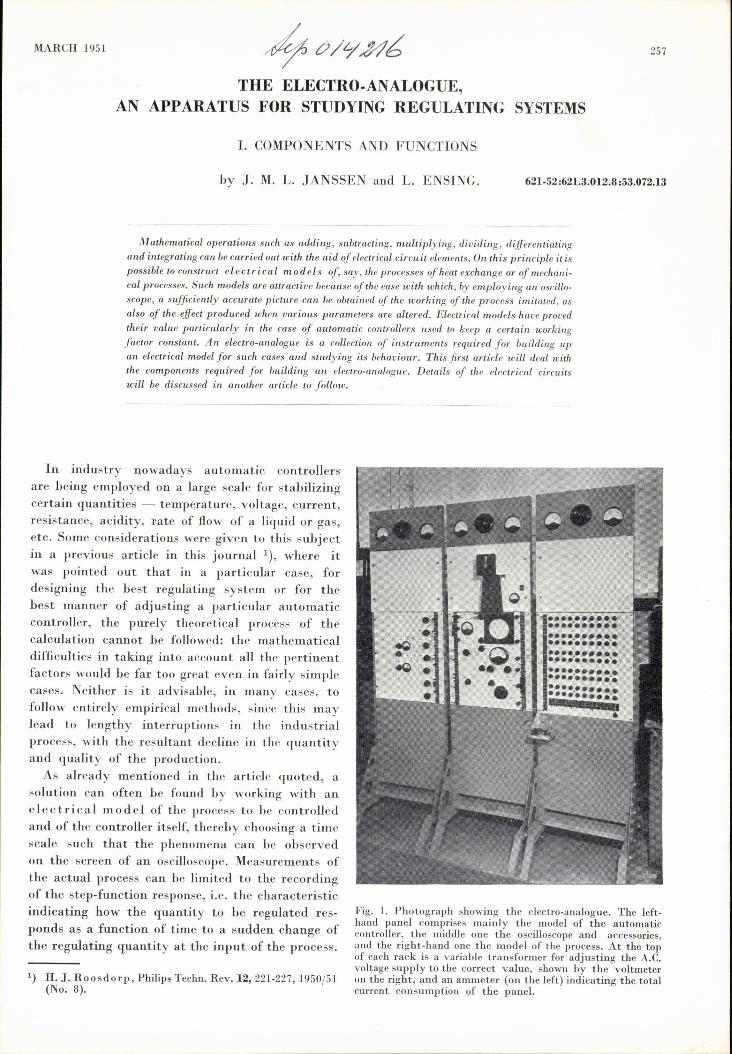
There has been no lack of attempts to put thestep-function response of a more or less idealizedprocess into mathematical form and then to trans-late that form into an electric network serving asa "process analogue", i.e. as an electrical modelof the process.Many processes are mainly characterized by an
inertia caused, for instance, by a thermal resis-tance and a thermal capacity. Obviously in suchcasès the process analogue can to a first approx-imation be composed of a resistance R and a capa-
'rn,S_[____(j2 t-Rc
64Y44
Fig. 2. a)'Ucsistor R arid capacitor e in series, as the simplestelectrical model,ofa process with thermal resistance and thermalcapacity. b) Step-function response curve of this network.
",',
citance C in series (fig. 2a). The equation for thestep-function response of this circuit (fig. 2b) is:
x _!__= l-e RC.
xo
where Xo is the amplitude of the applied voltage step,x is the voltage across the capacitor and t is thetime.
6H45
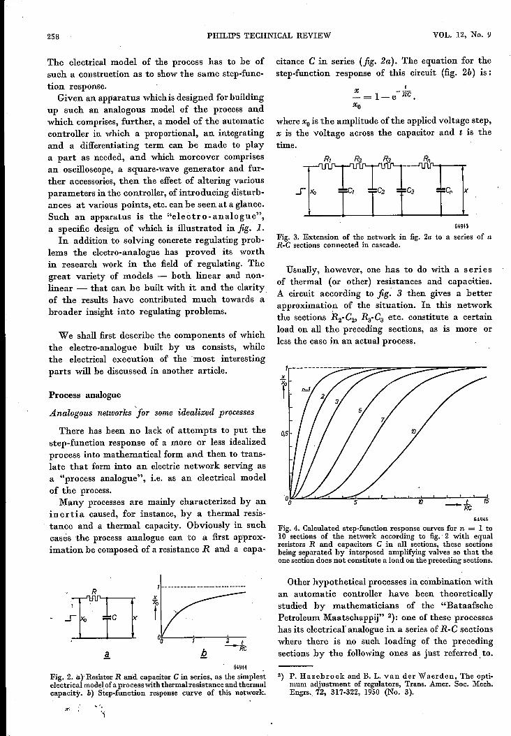
Fig. 3. Extension of the network in fig. 2a to a series of nR-e sections connected in cascade.
Usually, however, one has to do with a seriesof thermal (or other) resistances and capaci.ties.A circuit according to fig: 3 then gives a betterapproximatio~ of the situation. In this networkthe sections R2-C2, Ra-Ca etc. constitute a certainload on all the preceding sections, as is more orless the case in an actual process.
10 _.l.. 15RC
r.4Q4fi
Fig. 4. Calculated step-function response curves for n = 1 to10 sections of the network according to fig. 2 with equalresistors R and capacitors e in all sections, these sectionsbeing separated by interposed amplifying valves so that theone section does not constitute a load on the preceding sections.
Other hypothetical processes in combination withan automatic controller have been theoreticallystudied by mathematicians of the "BataafschePetroleum Maatschappij" 2): one of these processeshas its electrical analogue in a series of R-C sectionswhere there is no such loading of the precedingsections by the following ones as just referred, to.
2) P. Hazebroek and B. L. van der Waerden, The opti-mum adjustment of regulators, Trans. Amer. Soc. Mech.Engrs-, 72, 317-322, 1950 (No. 3).
MARCH1951 ELECTRO·ANALOGUE(COMPONENTSAND FUNCTIONS) 259
This case can be realized by separating the sectionsin the network of fig. 3 by means of amplifyingvalves (details will be given in a subsequent article).The calculated step-function response curves ofsuch a network for different numbers of sectionsare given in fig. 4.
To verify the proper functioning of the electro-analogue this is provided with both kinds of R-enetworks. The network without interposed valvesconsists of 20 "coupled", and that with valvesof 40 "decoupled" identical sections, any number
Fig. 5. Oscillogramsof the step-function responsecurves of10 sectionsof an Rs C network;upper curve with decoupledsections, lower curve with the sections not decouplcd.Thenpper curve agrees with the calculated curve for n = 10in fig. 4-, in which figure a widely different time scale hasbeen used.
of which can be used as required. Fig. 5 shows theoscillograms of the step-function responses of10 sections of both networks.These networks have rendered good service
particularly for research purposes, but they do notform a universal process analogue with which anystep-function response curve can be obtained. Toarrive at such a universal process analogue, insteadof adhering to an electrical analogy with thephysical working of the actual process, an entirelydifferent network has been devised by meansof which any step-function response can be suffi-ciently approximated by a discontinuous line.
Universal process analogue
In the universal process analogue used by usan electric delay network 3) is employed. Thisconsists of a large number of sections, made up ofcapacitors and inductors, so arranged that voltagesare transmitted, unattenuated, with a delay timer which over a very wide frequency range is inde-pendent of the frequency. When a voltage Vohaving the shape of a step-function is applied to the
3) British patent specificationNo. 517,516 in the name ofA. D. Blumlein, H. E. Kalhnann andW. S. Percival.
input of the network then the output voltage VIof the first section likewise has the shape of a step-function but the step is delayed by a time r (fig. 6)and is thus produced at to + t ; the voltage V2behind the second section, also with the shape ofa step function, makes the step at to + 2" andso on.
Jf one now has a device with which any arbitraryproportions al' a2, a3 ... of the voltages Vo, VI V2 •••
can be added - which proportions it must be possi-ble to adjust independently of each other betweenthe limits +amaxand -amax - then one can obtaina sum voltage Vs:
... ,of echelon shape as shown in fig. 7, and with this
cIr Isro
----t-to64g47
Fig. 6. Left: delay networkwith sections1, 2, 3, ... Whenavoltagestep Vo (seeright-handpart of the diagram)is appliedto the input then there arise at the outputs of the sectionsequally large pulses Vl, V2, V3 .•• lagginga time 1', 21', 3" ...behind VOo
~t
o
Fig. 7. When variablefractions a of the voltages Vo, VI' V2,
V3, ... of fig. 6 are added together, a sum voltage Vs ofechelon shape is obtained, with which any curve can beapproximated by varying the coefficientsa.
260 PHILlPS TECHNICAL REVIEW VOL. 12, No. 9
II,,,,,kj: I, ,
IMI ' , 'I I I, 'A'-----,., I/]I I I II: I I
I "I I II I: ....---, I ~
I ! U: I I I
I ::!I I I II 1:1/1: I I l II ! I I I
I I i no T ST___ toto
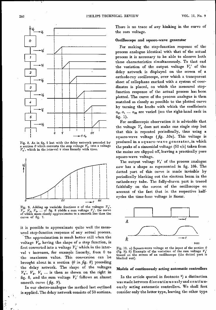
Fig. 8. As in fig. 6 but with the delay network preceded bya section 0 which converts the step voltage Vo into a voltageVO
f, which in the interval 1: rises linearly with time.
ISt
Fig. 9. Adding up variable fractions a of the voltages VOf,
Vl, V2, V3, ... of fig. 8 yields a sum voltage Vs', the curveof which more closelyapproximates to a smooth line than thecurve of fig. 7.
it is possible to approximate quite well the meas-ured step-function response of any actual process .. The approximation is much bettcr still when tbe
voltage Vo, having the shape of a step function, isfirst converted into a voltage Vo' which in the inter-val 1: increases, for example linearly, from 0 tothe maximum value. This conversion can bebrought about in a section (0 in fig. 8) precedingthe delay network. The shape of tbe voltagesVo', VI' V2 ••• is then as shown on the right infig. 8, and the. sum voltage Vs' follows an almostsmooth curve (fig. 9).
In our electro-analogue the method last outlinedis applied. The delay network consists of 50 sections.
o -.t
There is no trace of any kinking in the curve ofthe sum voltage.
Oscilloscope and square-wave generator
For making the step-function response of theprocess analogue identical with that of the actualprocess it is necessary to be able to observe boththese characteristics simultaneously. To that endthe variation of the output voltage Vs' of thedelay network is displayed on the screen of acathode-ray oscilloscope, over which a transparentsheet of cellophane marked with a system of coor-dinates is placed, on which the measured step-function response of the actual process has beenplotted. The curve of the process analogue is thenmatched as closely as possible to the plotted curveby turning the knobs with which the coefficientsao, al'" a50 are varied (see the right-hand rack infig. 1).
For oscilloscopic observation it is advisable thatthe voltage Vo does not make one single step butthat this is repeated periodically, thus using asquare-wave voltage (fig. lOa). This voltage isproduced in a square-wave generator,in whichthe peaks of a sinusoidal voltage (50 cIs) taken fromthe mains are clipped off, leaving a practically puresquare-wave voltage.
The output voltage Vs' of the process analoguenow has a shape as represented in fig. lOb. Thedotted part of this curve is made invisible byperiodically blacking out the electron beam in thecathode-ray tube. The fully-drawn part is tracedfaithfully on the screen of the oscilloscope onaccount of the fact that in the respective half-cycles the time-base voltage is linear.
64Y51
Fig. 10. a) Square-wave voltage at the input of the section 0(fig. 8). b) Example of the variation of the sum voltage Vs'traced on the screen of an oscilloscope (the dotted part isblacked out).
Models of continuously acting automatic controllers
In the article quoted in footnote 1) a distinctionwas made between dis con tin u ous ly and con ti nu-ously acting automatic controllers. We shall firstconsider only the latter type, leaving the other type

MARCH 1951 ELECTRO-ANALOGUE (COMPONENTS AND FUNCTIONS) 261
of controllers to he dealt with in the last sectionof this article.In the equation for the relation existing hetween
the amount x hy which the quantity to he regulateddeviates from the desired value and the amountq hy which the regulating quantity is consequently
64951
Fig. 11. a) Block diagram of a model of an automatic controllerwith proportional action: amplifierA and variable attenuator Za.b) Block diagram of the model of an automatic controllerwith proportional, integral and derivative action. A is acommon amplifier, I the integrator, D the differentiator. Thecoefficients a, band c of the three components are adjustedby means of the variable attenuators Za, Zb and Ze respectively.SI is a collecting stage in which the three components areadded together.
changed hy the automatic controller, variousterms may occur, e.g. a proportional, an integratingand a differentiating term 4):
f dxq = - ax - b x dt - c - = ql + q2 + q3.. dt
It must he possible to realize these three terms inthe electrical model of the automatic controller andthe coefficients a, band c have to he variahle inthe model.
T:Q.eproportional term, ql = - a x, is easily rea-lized hy means of an electronic amplifier. The coef-fiçient a can he made variahle hy adding a variahleattenuator (fig. lla).The integrating term, q2 = -bIx dt, 0 and . the
differentitating term, q3 = -c dx/dt, are ohtainedwith the aid of an integrating and a differentiatingnetwork respectively. Separate attenuators providefor the variahility ofthe coefficients band c (fig.llb).Finally the three voltages, ql' q2 and q3' are sum-mated in a "collecting stage".
ol) In order to get positive numerical values of a, band c wehave given these factors a minus sig~;)in deviation fromthe article quoted in footnote 1). That q and x must havedifferent signs follows from the fact that the automaticcontroller has to bring about a change of q counteracting apreceding variation of x.
The electro-analogue is provided with a secondintegrator and a second differentiator hy meansof which terms of the type b2f f x dt dt and C2d2x/dt2can also he added, though as a rule there is no needfor this.
Form and location of the disturbances
When a process analogue has heen huilt up inthe manner descrihed then this network is com-hined with the model of the automatic controlleraccording to fig. 11 b to form a closed circuit(fig. 12). Contrary to fig. llb, a common attenuatorZo is added with which the coefficients a, band care varied simultaneously.
The oscilloscope can he connected to variouspoints of the circuit hy means of a lead. When itis found that the situation is stahle - this can al-ways he reached by adjusting Zo for sufficientattenuation - then at all input and output termin-als of the component parts of the regulating circuitthe voltage will be zero. Upon a disturhancebeing introduced somewhere, then at the outputof the process analogue and at that of the modelof the automatic controller voltages will arise whichare proportional to the quantities x or q respectively,and on the screen of the oscilloscope it can be seenhow these voltages vary 0 with different values ofthe coefficients a, band c.
The disturbances occurring in a regulatingsystem in practice can be distinguished hoth ac-
(1)
Fig. 12. Block diagram of the model of a regulating circuit,P' process analogue, whose step-function response has beenmatched to that of an actual process. Zo, A, Za, Zb, Z" I, Dand S1 form the model of the automatic controller (fig. ll).G square-wave generator supplying a disturbance, which canbe applied, for instance, to the input of the process (at Si)or at its output (at the collecting stage S2 p,rovided for thatpurpose). The oscilloscope Osc can be connected to variouspoints of the circuit. Zo is a common attenuator.
262 PHILlPS TECHNICAL REVIEW
cording to their form (as function of the time)and according to the point at which they occurin the circuit.
In respect to their form there are continuousand step disturbances. Since the former may beregarded as being the limit of an infinitely largenumber of infinitesimal steps occurring in succes-sion (cf. fig.6), it is only necessary to investigatethe response of the system to step disturbances.These can therefore be obtained from the square-wave generator employed for adjusting the processanalogue.According to the point at which they occur,
one may distinguish between:1. disturbances in the regulating unit, thus at the
input of the process,2. disturbances somewhere in the course of the
process, and3. disturbances in the detecting element, thus at
the output of the process.There mayalso be counted among these "distur-
bances" the changes resulting from the automaticcontroller being adjusted to a different setting.It is with these distinctions in mind that the square-wave generator is also fitted with a lead for connect-ing it either to the input of the process (i.e. to theinput of the collecting stage SI) or to the output
tx
a
VOL. 12, No. 9
of the process, for which purpose a second collect-ing stage, 52' is provided. If the disturbancesintroduced at these two points are sufficientlyneutralized by the automatic controller then thesame will be the case with the disturbances sub (2)occurring somewhere in the course of the process.
Oscillograms obtained with models of continuouslyacting automatic controllers
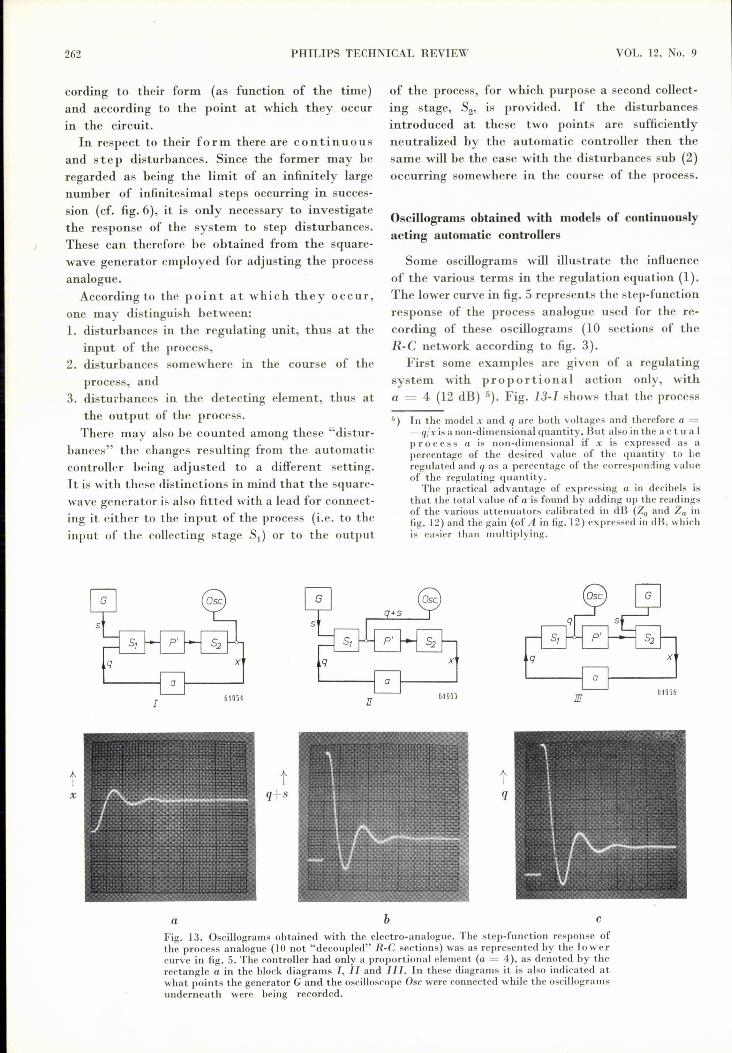
Some oscillograms will illustrate the influenceof the various terms in the regulation equation (1).The lower curve in fig. 5 represents the step-functionresponse of the process analogue used for the re-cording of these oscillograms (10 sections of theR-e network according to fig. 3).
First some examples are given of a regulatingsystem with proportional action only, witha = 4 (12 dB) 5). Fig. 13-1 shows that the process
5) In the model x and q are both voltages and therefore a =-q/xis a non-dimensional quantity. But also in the act u a Ipro ces s a is non-dimensional if x is expressed as apercentage of the desired value of the quantity to beregulated and q as a percentage of the corresponding valueof the regulating quantity.
The practical advantage of expressing a in decibels isthat the total value of a is fauna by adding up the readingsof the various attenuators calibrated in dB (Zo and Za infig. 12) and the gain (of A in fig.12) expressed in dB, whichis easier than multiplying.
IJ
tq+s
b
q x
a
1IJfi49jfi
tq
cFig. 13. Oscillograms obtained with the electro-analogue. The step-function response ofthe process analogue (10 not "decoupled" R-e sections) was as represented by the lowercurve in fig. 5. The controller had only a proportional element (a = 4), as denoted by therectangle a in the block diagrams I, IJ and Ill. In these diagrams it is also indicated atwhat points the generator G and the oscilloscope Osc were connected while the oscillogramsunderneath were being recorded.

MARCH 1951 ELECTRO-ANALOGUE (COMPONENTS AND FUNCTIONS)
analogue received, via the collecting stage SI' thesum of the output voltage of the controller q = -a xand the step-function voltage s from the square-wave generator, and that the output x from theprocess analogue was fed into the oscilloscope.
tx
a
tx.
d
263
From the oscillograms it is seen that in courseof time x and q + s (thus q) become constant.The final values are related to the quantity a inthe following way.
The gain of the process analogue (temporarily
tq
tq+s
b
tq+s
e
c
tq
fFig. 14,.As in fig. 13 but with an automatic controller having proportional and int e g ralaction. For the oscillograms (a), (b) and (c) the values of the coefficients were a = 1.6 andb = 1.25 rnil lisec+", whilst for the oscillograms (d), (p) and (f) these were a = 3.2 and IJ =3.2 millisec-1•
Fig. 13a is the oscillogram obtained, on the samescale as fig. 5.
Fig. l3-Il shows how q + s is fed into theoscilloscope. In the corresponding oscillogram(fig. l3b) it is easy to distinguish the step-functionvoltage s from the square-wave generator, followedby the oscillation of q.
disconnected from the automatic controller) is soadjusted that a step disturbance with the amplitudes, introduced at the input, causes a change in theoutput voltage the final of value which, x=, isjust equal to s. If, in the closed circuit, at theinput of the process analogue we have in additionthe output voltage q from the automatic controller

264 PHILlPS TECHNICAL REVIEW
with the final value qoo' then m the stationarystate we find:
In the automatic controller the equation
holds. From these two equations it follows that
1xoo=---s (4)
l+a
-aand qoo= ---8. (5)
l+a
From (4) it is seen that the larger the quantity athe smaller Xoobecomes - i.e. the better a disturb-ance is neutralized - but that Xoo never becomesexactly zero (offset). Equation (5) can be numeric-ally verified in fig. 13b, for which a = 4.According to fig. 13-111, in the collecting stage
S2 the step voltage 8 is added to the output voltageof the process analogue, the sum being termed x.Since the automatic controller contains only a
I
tx
a
proportional term the oscillogram of q (fig. Bc)is of the same shape as that in fig. 13b.
When the automatic controller contains an in te-grating element (fig. 14) then, as already ex-plained in the article quoted in footnote 1), x isindeed reduced exactly to zero after a disturbancehas occurred. With the exception of the integratingelement the networks I, IJ and III of fig. 14correspond to those of fig. 13. The respective oscillo-grams in figs 14a, 14b and 14c relate to the casewhere a = 1.6 (4 dB) and b = 1.25 millisec",while the oscillograms in figs 14d, 14e and 14frelateto the case where a = 3.2 (10 dB) and b = 3.2millisec-1•
The oscillograms in figs 14c and 14f can be inter-preted as follows: owing to the inertia of the processanalogue the prescence of this part is not yet notice-able immediately after the step. The oscilloscopethus shows a step -as (in the oscillogram a stepupward). This is first followed by a linear rise, cor-responding to the presence of the integrating ele-ment in the automatic controller, yielding a voltage-b Is-dz = -b 8 t 'which increases linearly with time.Then, however, comes evidence of the presence
(2)
(3)
b
VOL. 12, No. 9
a 64961
tq+8
b
b 1---+----
64962m
tq
c
Fig. IS. As in fig. 14 but with also a derivative action in the regulator (a = 3.2,b = 3.2 millisec-'. c = 1 millisec}.

MARCH 1951 ELECTRO-ANALOGUE (COMPONENTS AND FUNCTIONS) 265
tx
tx
a
'"Iq+s
tq+s
b
tq
abcFig. 16. As in fig.13, but with the process analogue consisting of a network (10 "decoupled"R-e sections, with a step-function response as represented by the up p er curve offig. 5. Herethe coefficient a of the proportional term was 1.
tq
Fig. 17. As in fig. 14 but with a process analogue formed by a network with a step-functionresponse as represented by the upper curve of fig. 5. a = 0.5 ,b = 2 miljisec='.
c
tx
a
tq+s
of the process analogue, which now also contributesa certain voltage to the input of the automaticcontroller. In the final state again equation (2)holds, but since now x= = 0 we find q= = -s,which means to say that in order to neutralize aninterference at the output of the process apermanent change in the position of the reg-ulating unit is necessary. Further the initialstep qo made by q is equal to -a s. The ratio
Fig. 18. As in fig. 15 but with a process analogue formed by a network with a step-fundionresponse as represented by the upper curve of fig. 5 and with coefficients (I ~ 0.5,b = 2.5 rnil liscc+", c = 0.08 milliscc,
b
+q
c
of this step to the final value of q, thus qo/q=,is therefore equal to a, as may be seen fromfigs 14c anf 14f
Finally in jig. 15 similar oscillograms are shownfor the case where the automatic controller con-tains also a differentiating element (a = 3.2,b = 3.2 millisec", c = 1 millisec). Apparently thedifferentiation has a stabilizing effect upon theregulation.
266 PHILIPS TECHNICAL REVIEW VOL. 12, No. 9
Similar curves, hut recorded with a process analogue witha step-function response as shown hy the upper curve infig. 5, are represented infigs 16. 17 and 18 on the same scale
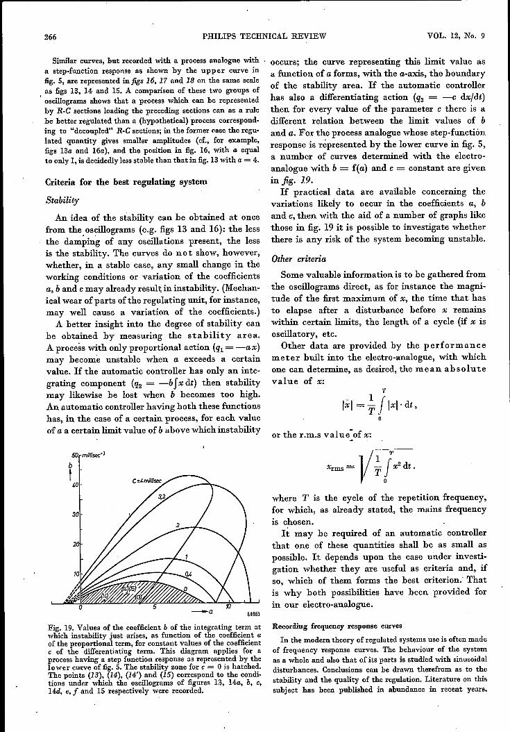
, as figs 13, 14 and 15. A comparison of these two groups ofoscillograms shows that a process which can he representedhy R-G sections loading the preceding sections can as a rulehe hetter regulated than a (hypothetical) process correspond-ing to "decoupled" R-G sections; in the former case the regu-lated quantity gives smaller amplitudes (cf., for example,figs 13a and 16a), and the position in fig. 16, with a equalto only 1, is decidedly less stable than that in fig. 13with a = 4.
Criteria for the best regulating system
Stability
An idea of the stability can be obtained at oncefrom the oscillograms (e.g. figs 13 and 16): the lessthe damping of any oscillations present, the lessis the stability. The curves do not show, however,whether, in a stable case, any small change in theworking conditions or variation of the coefficientsa, band cmay already result; in instability. (Mechan-ical wear of parts of the regulating unit, for instance,may well cause a variation of the coefficients.)
A better insight into the degree of stability canbe obtained by measuring the stability area.A process with only proportional action (ql= -ax)may become unstable when a exceeds a certainvalue. If the automatic controller has only an inte-grating component (q2 = -b Jx dt) then stabilitymay likewise be lost when b becomes too high.An automatic controller having both these functionshas, in the case of a certain process, for each valueof a a certain limit value of b above which instability
Fig. 19. Values of the coefficient b of the integrating term atwhich instability just arises, as function of the coefficient aof the proportional term, for constant values of the coefficientc of the differentiating term. This diagram applies for aprocess having a step function response as represented by thelower curve of fig. 5. The stability zone for c = 0 is hatched.The points (13), (14), (14') and (15) correspond to the condi-tions under which the oscillograms of figures 13, 14a, b. c,14d, e, f and 15 respectively were recorded.
occurs; the curve representing this limit value asa function of a forms, with the a-axis, the boundaryof the stability area. If the automatic controllerhas also a differentiating action (q3 = -c dxJdt)then for every value of the parameter c there is adifferent relation between the limit values of band a. For the process analogue whose step-functiónresponse is represented by the lower curve in fig. 5,a number of curves determined with the electro-analogue with b = f(a) and c = constant are givenin fig. 19.If practical data are available concerning the
variations likely to occur in the coefficients a, band c, then with the aid of a number of graphs likethose in fig. 19 it is possible to investigate whetherthere is any risk of the system becoming unstable.
Other criteria
Some valuable information is to be gathered fromthe oscillograms direct, as for instance the magni-tude of the fust maximum of x, the time that hasto elapse after a disturbance before x remainswithin certain limits, the length of a cycle (if x isoscillatory, etc.
Other data are provided by the performancemeter built into the electro-analogue, with whichone can determine, as desired, the m ea nab sol u t evalue of x:
T
lxi= ~f l=l:dt,o
or the r.m.s val ue- of x:
where T is the cycle of the repetition frequency,for which, as already stated, the mains frequencyis chosen.
It may he required of an automatic controllerthat one of these quantities shall be as small aspossible. It depends upon the case under investi-gation whether they are useful as criteria and, ifso, which of them forms the best criterion.' Thatis why both possibilities have been provided forin our electro-analogue.
64963
Recording frequency response curves
In the modern theory of regulated systems use is often madeof frequency response curves. The behaviour of the systemas a whole and also that of its parts is studied with sinusoidaldisturbances. Conclusions can he drawn therefrom as to thestability and the quality of the regulation. Literature on thissubject has heen published in abundance in recent years.

MARCH 1951 ELECTRO-ANALOGUE (COMPONENTS.AND FUNCTIONS) 267
For sinusoidal disturbances to he introduced in themodel of the regulating system the electro-analogue hasbeen provided with an R-C oscillator the frequency ofwhich is variable. This oscillator can he connected, forinstance, to the collecting stage Si of the closed regulatingcircuit (fig. 20). In this way sinusoidal voltages arise at allpoints of the circuit. By measuring the input and output
Fig. 20. Arrangement for taking Nyquist diagrams of theclosed circuit of the process analogue P' and the model R'of the automatic controller. The (~ariable frequency) genera-tor RC supplies a sinusoidal voltage VlO which in the collectingstage Si is added to the output voltage Vs from R'.
voltages of any element in the circuit one can determinethe frequency response of that element. The same can be donefor two or more elements connected in cascade, and even forthe cascade connection of all the parts making up the circuit.In the latter case it is possible to derive from the measurementsthe Nyquist diagram, from which, as is known, conclusionscan be drawn regarding the stability of the system 6). Usuallythe measurements for the Nyquist diagram are taken afterthe circuit has been opened at some point. If, however, thereis an integrator in the automatic controller (or the model)this is not possible, because when the circuit is cut open itbecomes unstable: in fact the integral of an accidental stepdisturbance would continue to increase unrestricted, becausein the opened circuit the disturbance is not neutralized. Inthat case the Nyquist criterion in its original form doesnot hold. In literature other forms of a wider scope are indi-cated 7), but it would lead us too far afield to go into these here.
Models of discontinuously acting automatic con-trollers
Automatic controller with two-step actionThe simplest form of a discontinuously acting
automatic controller is that in which the regulatingunit can have only two positions (as is the case, forinstance, with a thermostat), so that the regulatingquantity can assume only two values, Q1 or Q2'Fig. 21a represents the case - already discussedin the article quoted in footnote 1) - where Q = Q1so long as the quantity X to be regulated is greaterthan a critical value Xcr, and Q = Q2 so long asX < Xcr; usually it is so arranged that Xcr is justthe desired value Xo. Between Q1 and Q2 is a valueQo at which - if Q could assume that value -
6) H. Nyquist, Regeneration theory, Bell Syst. techno J.11, 126-147, 1932. See also B. D. H. Tellegen, PhiJipsTechn. Rev. 2, 292, 1937.
7) H. Bode, Network analysis and feedback amplifier design(Chapter VIII), New York 1945, and F. Strecker, Dieelektrische Selbsterregung, Stuttgart 1947.
under normal working conditions X would havejust the desired value Xo' Instead of tb at, theregulating unit is alternately in the positions Q1and Q2' If it is desired to change over to a differentvalue of Xo then Qo has to he given a differentvalue too. If, however, Qo becomes greater thanQ2 or less than Q1 then the automatic controllerno longer functions.In practice the tr~nsition from Q1 to Q2 will not
usually take place at exactly the same value ofX as the change-over from Q2 to Q1: owing to back-lash in the mechanical parts of the regulating unitfor instance, or owing to the difference between thecurrent at which a relay is closed and that at whichit is opened, the transitions take place at differentvalues of X (Xl and X2) either side of Xo' Insteadof fig. 21a we then get fig. 21b. Denoting the devia-tions of Q and X from the equilibrium valuesagain by q and x, then q = Q - Qo and x = X - Xo;the regulating cycle q = f(x) for an automaticcontroller with two-step .action having backlashthen has the shape shown in fig. 21c.
ot
64g65
Fig. 21. Automatic controllers with two-step action, (a) with-out, (b) and (c) with backlash. In case (a) the regulating unittakes up the position corresponding to Q = Ql < Qo when Xis greater than the desired value Xo' and Q = Q2 > Qo whenX < Xo (Qo is the - impossible - position in which undernormal working conditions X would assume the value Xo).b): The same but with a backlash X1-X2• In (c) the quantitiesq = Q - Qo and x = X - Xo have been plotted againsteach other for the case (b).
The presence of backlash naturally reduces the responsesensitivity and the accuracy of the regulation, but there isalso a good side to it. In the case of an automatic controllerwithout any backlash the regulating unit takes up the otherposition as soon as there is the least difference between Xand Xcr, whereas in the case of a controller with backlashthis does not take place until that differencereaches a certainvalue. In. the latter case, therefore, the regulating unit isless subject to mechanical ~ear, and that is why sometimessome backlash is purposely given to the regulating unit.
It appears to he possible to build up electric cir-cuits which show a relation between the outputand the input voltages similar to that existing be-tween q and x according to the hysteresis loop offig. 21c. Such a circuit can serve as an electricalmodel for an automatic controller with two-stepaction. If, for instance, a sinusoidal voltage (x in

26B PHILIPS TECHNICAL REVIEW
.fig. 22) is applied to this circuit then a square-waveoutput voltage (q) is obtained.
In the electro-analogue containing such a circuitthe latter can be combined with the process analogueto form a closed regulating circuit (fig. 23), inwhich also an amplifier, variable attenuators anda collecting stage are included. The limit X2 = -Xl
is governed in the circuit by a direct voltage; thusby changing this voltage it is possible to vary thewidth of the loop. Via the collecting stage a direct
tt q
ql - '-------' - -- --- ---'-- --l
Fig. 22. When a sinusoidal voltage ~: (with amplitude greaterthan the limits x2 = -X, of the backlash) is applied to anelectric network forming the model of an automatic controllerwith two-step action there arises at the output uf the networka square-wave voltage q.
t tX X
VOL. 12, No. 9
Fig. 23. Regulating circuit for studying discontinuously actingcontrolers (model R'). P' process analogue. Via the collectingstage S a direct voltage s can be applied to form the analogueof a disturbance or of a transition to some other desiredvalue in the actual controller.
voltage s can be added, corresponding to a variationof Qo or to bringing about a variation of Qo.In figs 24a, band c oscillograms of q and X are
represented respectively for s = 0, s = +5 V ands = - 5 V, where changes takes place in tbe ratioof the intervals in which q has the value ql or q2respectively.
Automatic controller with three-step actioti
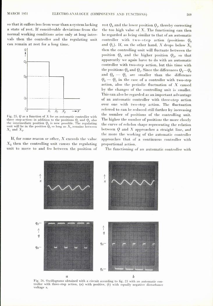
By giving the regulating unit a third position,Qo, in between the positions QI and Q2 (fig. 25)one has the advantage that the system is at restso long as the value of X is between Xl and X2•
a b c
Fig. 24-. Oscillograms obtaincd with a circuit according to fig. 23 with an automatic con- .trollcr with two-step action. In the case (a) s = 0 and thus Qo lies halfway between Qland Q2 (fig. 21b). The intervals during which q = q, and q2 respectively are of equallength.In the case (b) s is positive and in case (c) equally negative; the intervals during whichq = ql and q2 respectively are here unequal.
MARCH 1951 ELECTRO-ANALOGUE (COMPONENTS AND FUNCTIONS) 269
so that it suffers less from wear than a system lackinga state of rest. If considerable deviations from thenormal working conditions arise only at long inter-vals then the controller and the regulating unitcan remain at rest for a long time.
ot
Fig. 25. Q as a function of X for an automatic controller withthree step-action: in addition to the positions Ql and Q2 alsothe intermediate position Qo is now possible. The regulatingunit will be in the position Qo so long as Xo remains betweenx, and X2•
If, for some reason or other, X exceeds the valueX2 then the controlling unit causes the regulatingunit to move to and fro between the position of
00 ------ L-__ .....,
,,IIIIII
0, ... T i00 x, Xo X2 -x
tx
a
rest Qo and the lower position Ql' thereby correctingthe too high value of X. The functioning can thenbe regarded as being similar to that of an automaticcontroller with two -st ep action (positions Qoand Ql)' If, on the other hand, X drops below Xlthen the controlling unit will fluctuate between theposition Qo and the higher position Q2' so thatapparently we again have to do with an automaticcontroller with two-step action, but this time withthe positions Qo and Ql' Since the differences Q2- Qoand Qo - QI are smaller than the differenceQ2 - QI in the case of a controller with two-stepaction, also the periodic fluctuation of X causedby the changes of the controlling unit is smaller.This can also be regarded as an important advantageof an automatic controller with three-step actionover one with two-step action. The fluctuationreferred to can be reduced still further by increasingthe number of positions of the controlling unit.The higher the number of positions the more closelythe curve of echelon shape representing the relationbetween Q and X approaches a straight line, andthe more the working of the automatic controllerapproaches that of a continuous controller withproportional action.The functioning of an automatic controller with
tx
bFig. 26. Oscillograms obtained with a circuit according to fig. 23 with an automatic con-troller with three-step action, (a) with positive, (b) with equally negative disturbancevoltage s.

270 PHILIPS TECHNICAL REVIEW VOL. 12, No. 9
three-step action is illustrated by the oscillogramsin fig. 26. In this case, by applying a positive or anegative voltage s to the input of the process ana-logue, the rest level Qo was shifted in such a way thatthe controller came into action and moved to andfro between the positions Qo and Q2' respectivelybetween the positions Qo and Ql·
Multi-speed floating control
Instead of the regulating unit being so made thatit can only take up certain pos i t ion s, it can hearranged so as to run with a certain, constant,speed dqfdt in the one direction or in the other orremain at rest according to the value of x. Forinstance:
dqfdt
dqfdt
dqfdt
-p when X > X2'
o when X2 > X > Xl'
+p when X < Zl.and
This is made technically possible, for instance, byhaving a controlling unit with three-step actiondriving a servomotor which operates the regulatingunit and turns at a constant speed in one direction
t tXX
a
tx
d
or the other or remams at rest according to theposition of the controlling unit. The motor thenadjusts the regulating unit by an amount q varyinglinearly with the time: q = Ip dt = pt + const.
tt
64969Fig. 27. When an alternating voltage x is applied to the inputof an electric network forming the analogue of an automaticcontroller with three-step action the output voltage q assumesthe shape of the drawn trapezium.
Compared with the automatic controller withthree-step action, the multi-speed floating controlhas the advantage that in the event ofpermanentchange from the normal (average) working condi-tions the motor provides for a permanent readjust-ment of the regulating unit.
tq
b c
tq
eFig. 28. a) Step-function response of a process analogue which together with an automaticcontroller with three-step action formed a regulating circuit from which the oscillograms(b) - (e) have been recorded. (b) and (c) represent the variation of x and q respectively inthe case of a step disturbance at the input of the process, (d) and (e) the same quantitieswhen a disturbance is applied at the output.

MARCH 1951 ELECTRO-ANALOGUE (COMPONENTS AND FUNCTIONS) 271
ABSTRACTS OF RECENT SCIENTIFIC PUBLICATIONS OF TilEN.V. PHILIPS' GLOEILAMPENFABRIEKEN
Reprints of these papers not marked with an asterisk can be obtained free of chargeupon application to the Administration of the Research Laboratory, Kastanjelaan,Eindhoven, Netherlands.
1934: W. de Gr oot: The radiation constantsand the light equivalent of energy (Physica,The Hague 16, 419-420, 1950', No. 4).
Hoffmann has drawn attention to the fact thatthe discrepancy hetween the experimental andthe theoretical values ofthe Stephan-Boltzmannconstant a and the Planck constant C2 would dis-appear simultaneously if the figure for the freezingpoint of gold (TAu) were à few degrees higher thanthe internationally adopted value of 1336 OK. It isshown that the same holds true for the discrepancyhetween the experimental and the theoretical valuesof the light-equivalent of energy. At the same timeit is shown why Van Dusen and Dahl ohtainedan experimental c2-value in accordance with thetheoretical value.
In an electrical model the function of the motorcan he performed hy an integrating network.When the output voltage (-p, +p or 0) from amodel of an automatic controller with three-stepaction is applied to an integrating network thenat the output of that network there arises a voltageq which either increases or decreases linearly withthe time or remains constant, thus in analogy withthe readjustment of the regulating unit.If, for instance, a sinusoidal voltage (with ampli-
tude greater than x2) is applied to the input of theautomatic controller then it is easy to see (fig. 27)that at the output of the integrator there will hea trapezoidal voltage.
Fig. 28 shows some oscillograms recorded witha regulating circuit consisting of a process analogue,an automatic controller with three-step actionand an integrator. Fig. 28a is the step-functionresponse of the process analogue employed. Astep disturhance at the in put of the process ana-logue (corresponding to a sudden readjustmentof the regulating unit) produces the variation x:in the regulated quantity as illustrated in fig. 28b,and this in turn ~auses the voltage q at the inputof the process analogue to change according tofig. 28c. The consequences of a step disturhanceat the output of the process analogue are shown infigs 28d and e, respectively at the input and at theoutput of the process. In hoth these cases in the
final position x comes to rest at a value hetweenXl and x2•
The examples that have heen given here shouldhe sufficient to show how valuahle an aid theelectro-analogue is for studying regulating processes.Details of the electric circuits of various parts suchas the universal process analogue, the collectingstages, integrators and differentiators have purpose-ly heen omitted, since they will form the suhjectof a second article.
Summary. An electro-analogue is an apparatus with whichelectrical models of regulating devices can be built up andstudied. The electro-analogue discussed here comprises twospecial models and one universal model of the process to beregulated, the latter model consisting of an electric network- mainly a delay network - the step-function response ofwhich, displayed on the sereen of an oscilloscope, can be givena shape identical to that of any process to be imitated. Furtherthe electro-analogue comprises electrical models of automaticcontrollers with continuous action and of certain controllerswith discontinuous action. In the model of the continuouslyacting controller a proportional term, a single and a doubleintegrating term and a single and a double differentiatingterm can be realized.After the model of the process has been given the right
characteristie it is combined with one of the models of theautomatic controller to form a closed regulating circnit. Byapplying a step disturbance at a snitable point it is possibleto study with the aid of oscillograms the behaviour of thecircuit at different values of the parameters. In particularit can be investigated under what conditions instability arisesand how high the quality of the regulation is. Oscillogramsare given for various cases, both with continuously and withdiscontinuously acting controllers.A description of the electric>circuits of the principal parts
will be given in a subsequent, article. '
1935: C. J. Bouwkamp: On integrals occurringin the theory of diffractions of electromagneticwaves hy a circular disk (Proc. Kon. Ned.Akad. Wetensch. Amsterdam 53, 654-661,1950, . No. 5, Indigationes Mathematicae12, 199-206, 1950, No. 3).> .:
Evaluation of integrals occurring in the rigoroustheory of diffraction of a plane-polarized electro-magnetic wave hy a circular disk or hy a circularhole in an infinite plane screen, if the radius ofthe disk or hole is small compared to the wave-length. Expansions are given in terms of Le gendrefunctions, Bessel functions, and hypergeometricfunctions.
272 PHILIPS TECHNICAL REVIEW VOL. 12, No. 9
1936: C. J. Bquwkamp: On the theory of spheroi-dal wave functions of order zero (Proc. Kon.Ned. Akad. Wetensch. Amsterdam 53, 931-944,1950, No. 6; Indigationes Mathematicae12,.326-339, 1950, No. 3).
Spheroidal wave functions of order zero emergefrom a separation of the wave equation in spheroidalcoordinates in the case of' axially symmetric waveproblems. The author gives an account of theconventional theory of these functions. In addition,he draws attention to a new canonical system ofspheroidal wave functions which has many advan-tages over the conventional systems.
1937: W. J. Oosterkamp: Dose measurements oncontact therapy tubes (Acta Radiologica33, 491-506, 1950, No. 6).
The various causes of errors in contact-therapydosimetry are analysed and methods for avoidingthese errors are described. Extensive measurementshave been carried out with the Philips apparatusin regard to: the absorption characteristic of theradiation in aluminium, the half-value layer fordifferent added filters, the field distribution wherethe effect of a compensating filter is described, thedetermination of depth-dose data and of isodosecurves in a water phantom, the influence of secon-dary radiation from the applicators and the doserate of the stray-radiation around the tube causedby scattering from the patient. The dynamicelectrometer used proved to be very useful for thiskind of work. The results of the measurementsare compared with those obtained by other authors.
1938: H. O. Huisman: Investigations into thevitamin A series, -I. A new synthesis ofvitamin A acid and vitamin A (Rec. Trav.chim. Pays-Bas 69, 851-857, 1950, No. 6).
The chemical and physical properties of (J-ionylidene acetaldehyde, the important key inter-mediate for the synthesis of vitamin A, are given.Starting .from (J-ionylidene acetaldehyde a newsynthesis of vitamin A acid and vitamin A isdescribed.
1939*: W. Elenbaas, J. Funke, Th. Hehen-kamp, L. C. Kalff, A. A. Kruithof, J. L.Ou weltj es, L.M. C. Tou w, D~Vermeulen,R. van der Vee n: Fluorescentie-verlichting(edited by Prof. Dr. C. Zwikker), Meulen-hoff, Amsterdam 1950 (262 pp., 173 fig.).(Fluorescent lighting, English edition inpreparation. )
See Philips Techn. Rev. 12, 369, 1950, No. 12.
1940: B. D. H. Tellegen: De krachten tussentwee- stroomgeleiders (T. Ned. Radiog. IS,157-161, 1950, Nos 4 and 5). (The forcesbetween two steady currents; in Dutch.)
The forces between two steady currents can beconceived of as the resultant of fictitious attractingforces and fictitious couples which the elements ofcurrent exert on one another; the attracting forcesare proportional to the scalar product of the currentelements divided by the square of their distance;the couples are proportional to the vector productof the current elements divided by their distance.
1941: J. H. van Santen and G. H. Jonker:Electrical conductivity of ferromagnetic
. compounds of manganese with perovskitestructure (Physica, The Hague 16, 599-600,1950, Nos 7 and 8).
Repo~t on measurements of electrical conduc-tivity of polycrystalline ceramic compounds pre-viously studied (see No. 1932 of these reports).Graphs are given showing log f2 versus liT for(Lal_x Sr",)Mn0a with x as parameter and log f2versus x for T = 100 OK. A striking resemblanceis to be observed between the curves showingthe Curie temperature and saturation magneti-sation versus composition. Similar sets of curveshave been obtained for systems in which Sr isreplaced by Ca or Ba.
1942: F. de Boer, J. H. van Santen and E. J. W.Verwey: The electrostatic contribution tothe lattice energy of some ordered spinels(J. chem. Phys. 18, 1032-1034, 1950, No. 8).
The electrostatic contribution to the latticeenergy of some ordered spinels has been calculated.It is made plausible \,hat also in the case of certainspinels that do not show any long-range orderinga considerable amoU:~t of short-range orderingis to be expected. As· a consequence the latticeenergy of "inversed"· spinels containing differentions at octahedral positions is increased with res-pect to the corresponding "normal" spinels con-taining one type of ions at octahedral interstices.
1943*:E. J. W. Verwey: The role of the electric\
double layer in the hehaviour of lyophobiccolloids (Colloid chemistry - theoreticaland applied, Vol. 7,· Reinhold Publ. Corp.,New York 1950; p. 47-66).
Discussion of the properties of the electricdouble layer of colloid particles and its influenceon the interaction of particles (see Nos 1730,1769*, 1916 of these abstracts).