Embed Size (px)
Citation preview
THE EFFICACY OF ROTARY AND MANUAL
INSTRUMENTS IN ROOT CANAL DEBRIDEMENT.
A Mini-Thesis Submitted in Partial Fulfilment for the
MChD degree in Prosthodontics at the Faculty of
Dentistry, University of the Western Cape
CANDIDATE: DR DUDUZILE MADLABANE
STUDENT NUMBER: 2153837
PROPOSED DEGREE: MCHD PROSTHODONTICS
SUPERVISOR: PROF Y.I.OSMAN
ii
ii
THE EFFICACY OF ROTARY AND MANUAL
INSTRUMENTS IN ROOT CANAL DEBRIDEMENT
KEY WORDS
Scanning electron microscope
Nickel-titanium rotary instruments
K-file®
ProTaper®
Smear layer
Debris
Canal transportation
iii
iii
SUMMARY
It has been shown that the use of both manual and rotary instruments
result in the formation of a smear layer and debris during root canal
treatment. The amount that is formed depends on the type of
instrumentation used as well as the force applied.
Aim: The purposes of this study were
1. To use the scanning electron microscope to compare the cleanliness
of the root canal walls following rotary and manual debridement
methods
2. To assess the transportation of the apical part of the root canal
orifice when using different instrumentation techniques.
Materials and Methods:
Endodontic treatment was performed on extracted maxillary central
incisors following extirpation and debridement using the Protaper® nickel
titanium files and K-files. The teeth were randomly divided into three
groups.
Endodontic therapy performed simulated the clinical procedures, in which
the teeth were extirpated using a barbed broach to remove the necrotic
pulp. Pre-operative periapical radiographs were used to determine the
working length. Root canals were debrided using the two filing methods,
with copious irrigation using Sodium hypochlorite solution in a disposable
syringe with a 27gauge needle.
iv
iv
A follow up radiograph with a master apical file in position was used to
verify complete debridement in the apical third of the canal.
The teeth were then sectioned vertically using a diamond bur to create an
initial groove and then split apart using a flat plastic instrument to
separate the sections and to avoid contamination of the sections. These
sectioned portions were then studied under a scanning electron
microscope. The smear layer as well as the amount of debris was
evaluated.
Results:
The assessment of residual debris and smear layer formed, were assigned
numbers and tabulated. All three areas of the root canal were compared
against each other. The sectioned apical third of the root canal was also
studied for the presence or absence of apical transportation.
Conclusion:
From the present study, it was found that both the nickel-titanium rotary
files and stainless steel hand files produced some smear layer and there
was some residual debris left in uninstrumented areas of the root canal.
However, it was shown that there was more smear layer formation when
using nickel-titanium rotary files compared to that formed using hand
files.
When assessed for the presence of apical transportation, it was found
that both types of instrumentation resulted in some degree of
transportation, however, with rotary files, the canals remained largely
centralized with transportation clearly visible in hand instrumented canals
v
v
DECLARATION
I hereby declare that the efficacy of rotary and manual instruments in
root canal debridement is my own work, that it has not been submitted
before for any degree or examination in any University, and that all the
sources I have used or quoted have been indicated and acknowledged by
complete references.
Madlabane Duduzile
Signed………………………………..
May 2009
vi
vi
ACKNOWLEDGEMENT
I would like to send my utmost gratitude to my supervisor Professor YI
Osman for his constant guidance and extensive overall knowledge. He is
such a well-read and well-grounded lecturer, who has led to a better
research product. You will always be my role model, thank you for your
patience.
I would like to thank Professor SR Grobler, for allowing me to use the
desiccator to dry my specimens.
I would also like to thank my colleague Dr S Cassim, for making our study
together so successful and fulfilling. Thanks partner for allowing me to
shed a tear or two.
My gratitude goes to the support staff, Linda and Carlene, for making the
clinical environment pleasant, also Robinson who was our assistant in the
first year of study.
Special thanks, to the staff of the Physics department, especially Dr
Julies and Mr. A Josephs. They guided me through the whole SEM study,
and the interpretation of some of the results. Mr. Josephs thanks for
being there for me always. Your guidance is highly appreciated.
vii
vii
DEDICATION
This work is dedicated to:
• My daughters Gugulethu and Ongiwe for their love and support, for
allowing me to sacrifice them during my four years of study
• My long-term partner and the father of my children for his
encouragement, during my study period and for allowing me to
pursue my chosen field
• My supervisor for his guidance, encouragement and support
ensuring that this project was a success.
• My mother for her love and support always
viii
viii
TABLE OF CONTENTS
TITLE PAGE………………………………………………………………………………………………i
KEY WORDS……………………………………………………………………………………………..ii
SUMMARY………………………………………………………………………………………………..iii-iv
DECLARATION………………………………………………………………………………………..v
ACKNOWLEDGEMENT…………………………………………………………………………..vi
DEDICATION………………………………………………………………………………………….vii
TABLE OFCONTENTS……………………………………………………………………….viii-x
LIST OF FIGURES…………………………………………………………………………… xi-xiii
CHAPTER 1……………………………………………………………………………………………….1
INTRODUCTION………………………………………………………………………….……….1-2
CHAPTER2……………………………………………………………………………………………….3
LITERATURE REVIEW…………………………………………………………………….…..3
2.1 Historical background……………………………………………………………………..3
2.2 Significance of the smear layer…………………………………………….……..3
2.3 Canal shaping and preparation………………………………………………………6
2.4 Sodium hypochlorite……………………………………………………………………….13
2.5 Instrument design…………………………………………………………………………..15
2.6 Properties of individual nickel-titanium rotary files……………….17
2.6.1 Profile and Profile GT files…………………………………………….17
2.6.2 LightSpeed…………………………………………………………………………19
2.6.3 Quantec………………………………………………………………………………20
2.6.4 K3………………………………………………………………………………………….21
2.6.5 Hero 642…………………………………………………………………………….21
2.6.6 RaCe……………………………………………………………………………………..22
2.6.7 Mtwo…………………………………………………………………………………….22
2.6.8 Oscillating/Reciprocating files………………………………………34
ix
ix
2.7 Profile and ProTaper in clinical use……………………………………………18
2.9 Cyclic fatigue of nickel-titanium instruments…………………………23-24
2.10 General fatigue of rotary instruments…………………………………….25
2.11 Surface debris after root canal preparation………………………….25-27
CHAPTER 3………………………………………………………………………………………………28
AIMS AND OBJECTIVES……………………………………………………………………28
3.1 Aims and objectives…………………………………………………………….28
3.2 Purpose of the study………………………………………………………….28
3.3 Statement of the problem…………………………………………….….29
3.4 Null Hypothesis…………………………………………………………………...29
CHAPTER 4………………………………………………………………………………………………30
MATERIALS AND METHODS…………………………………………………………….30
4.1 Specimen collection and preparation………………………………….……….30
4.1.1 Study sample and sample size…………………………………………30
4.2 Study design……………….…………………………………………………………………….31
4.2.1 Design…………………………………………………………………………………..31
4.3 Study sample………………………………………………………….………………………….31
4.3.1 Inclusion criteria………………………………………………………………..31
4.3.2 Exclusion criteria……………………………………………………………….31
4.4 Pilot study…………………………………………………………………………………………..31
4.5 Ethical consideration………………………….…………………………………………….32
4.5.1 Teeth collection…………………………………………………………………..32
4.5.2 Teeth disposal……………………………………………………………………..32
4.6 Endodontic therapy…………………………………………………………………………..33
4.6.1 Endodontic therapy on specimen……………………………………..33
4.7 Definitions…………………………………………………………………………………………..36
4.8 Scoring of smear layer and debris………………………………………………….36
4.8.1 Smear layer………………………………………………………………………………….…..36
x
x
4.8.2 Debris………………………………………………………………………………………………..37
4.9 Specimen preparation………………………………………………………………………..38
4.9.1 Preparation of specimen for scanning electron microscope
examination………………………………………………………………………………….….38
4.9.2 Specimen preparation for SEM evaluation and image
production……………………………………………………………………………….………38
4.10 Schematic representation of the study……………………………………….40
CHAPTER 5………………………………………………………………………………………………….41
RESULTS……………………………………………………………………………………………………..41
5.1 Apical transportation…………………………………………………………………………..41
5.2.Instrument separation………………………………………………………………………..53
CHAPTER 6……………………………………………………………………………………………………60
DISCUSSION……………………………………………………………………………………………..60-68
CHAPTER 7…………………………………………………………………………………………………..69
7.1 LIMITATIONS……………………………………………………………………………….…….69
CHAPTER 8…………………………………………………………………………………………….……..70
CONCLUSIONS AND RECOMMENDATIONS……………………………….…….70
8.1 Conclusions……………………………………………………………………………………………….70
8.2 Recommendations…………………………………………………………………………………..70
APPENDICES
Appendix I…………………………………………………………………………………………………….72-75
Appendix II………………………………………………………………………………………………….76-79
Appendix III……………………………………………………………………………………............80-83
Appendix IV………………………………………………………………………………………...........84-85
Appendix V…………………………………………………………………………………………...........86
Appendix VI………………………………………………………………………………………...........87
Appendix VII…………………………………………………………………………………………….…88
Appendix VIII……………………………………………………………………………………………..89
xi
xi
Appendix IX……………………………………………………………………………………………….90
REFERENCES…………………………………………………………………………………………….91-101
LIST OF FIGURES
Figure 4.1 extracted maxillary incisors…………………………………………..…..30
Figure 4.2 K-files………………………………………………………………………………….…..33
Figure 4.3 ProTaper………………………………………………………………………………….33
Figure 4.4 Multiple prepared specimens……………………………………………….38
Figure 4.5 Magnified single specimen……………………………………………………38
Figure 5.1 Apical transportation (single)………………………………………………39
Figure 5.2 Apical transportation (multiple)………………………………………….39
Figure 5.3 K-file transportation.…………………………………………………………….53
Figure 5.4 S1 ProTaper files………………………….…………………………………………53
Figure 5.5-5.7 Surface debris control.…..……………………………………………..54
Figure 5.8-5.9 1000 magnification.………………………………………………………….55
Figure 5.10-5.12 Surface debris (hand)...……………………………………………….56
Figure 5.13-5.15 Surface smear layer (hand).….……………………………………57
Figure 5.16-5.18 Surface debris (rotary)…………..…………………………………58
Figure 5.19-5.21 Surface smear layer (rotary)..…………………………………..59
LIST OF GRAPHS
Graph 5.1 Control group…………………………………………………………….…………………44
Graph 5.2 Surface debris (hand)…………………………………………….………………..46
Graph 5.3 Surface debris (rotary).………………………………………………………….48
Graph 5.4 Surface smear layer (hand)..…………………………………………………..50
Graph 5.5 Surface smear layer (rotary)………………………………………………….52
xii
xii
LIST OF TABLES
Table 5.I Apical transportation……………………………………………………………….42
Table 5.II Control debris score……………………………………………………………….43
Table 5. III Hand debris score………………………………………………….…………….45
Table 5.IV Rotary debris score………………………………………………………………..47
Table 5. V Hand smear layer………………………………………………………………………49
Table 5.VI Rotary smear layer…………………………………………………….……………51
1
1
CHAPTER 1
INTRODUCTION
The introduction of rotary instruments has made it easier for clinicians
to perform root canal therapy without too much operator fatigue,
because it has been shown that shorter treatment times are required to
complete the debridement procedure in the preparation of the canal walls
(Suffridge, Hartwell, Walker 2003, citing Beeson et al (2000).
However in recent years, Nickel-titanium instruments such as Profile®
and ProTaper (Dentsply Maillerfer), were developed and have been
constantly improved for use in endodontic therapy in order to continue to
reduce the known operator fatigue associated with conventional
endodontics, thereby resulting in the further reduction in treatment
times (Ahlquist et al 2001).
However, since fatigue was conclusively proven (Ahlquist et al 2001), to
be reduced with rotary instrumentation, the present study excluded
fatigue as a variable and concentrated on the amount of debris and smear
layer formed during root canal debridement. The predictability of root
canal preparation was found to be influenced by the design of the
instrument (Al-Omari, Dummer, Newcombe, Doller 1992) and the alloy
content of the newer instruments (Gulabivala, Jardine 1995) however, the
tactile skills of the operator still remains an important aspect in the final
shape of the debrided canals (Walia et al 1988).
2
2
The role of canal preparation, namely, shaping, has undergone a paradigm
shift, as noted by Gulabivala and Jardine (1995), from one fulfilling the
prime debriding function to one that is regarded more as access to the
complex canal system and its contents for the irrigant.
Beeson et al (2000) showed that using rotary nickel-titanium files for
canal instrumentation resulted in a significant reduction in chair time and
operator fatigue when compared with the use of hand K-file instruments
only.
According to Hata (1998) and Davies, Brayton, Goldman (1972) who
compared rotational techniques with circumferential filing techniques, it
was concluded that the rotational techniques left major areas of the root
canal walls uninstrumented. The use of the push-pull filing technique was
the one method that was encouraged by Davies, Brayton, Goldman 1972.
However, other researchers found no significant differences between
rotational and circumferential filing techniques, as seen experimentally in
extracted teeth (Walton 1976) or in clinical studies (McComb, Smith
1975).
In this study all rotary instruments were used in a crown- down movement
and manual filing was done using the standard three quarter turn and
pulling action for debridement, incorporating the circumferential filing
technique.
3
3
CHAPTER 2
LITERATURE REVIEW
2.1 Historical background
Civjan, Huget and DeSimon were the first to implement the use of nickel
titanium in endodontic rotary instruments in 1975. However, it was only in
1988 that Walia, Bantley and Gerstein established the feasibility of
producing such nickel titanium instruments, which exhibited significantly
greater elasticity and superior resistance to torsional fracture.
Despite the higher strength and flexibility, instrument separation can
still occur with nickel titanium (NiTi) instruments, especially after
extended use (Shen, Cheung, et al 2006), necessitating that the number
of times that these instruments are used be related to the type and
position of the teeth within the quadrant. Unfortunately, many of these
fractures occur unexpectedly and without any prior visible signs of
permanent deformation. Cyclic, static torsional and dynamic torsional
fatigue are said to be the most common causes of rotary NiTi instrument
fracture (Yao, Schwartz, Beeson 2006)
2.2 Significance of the smear layer in endodontics
It has been shown in a study performed by Torabinejad, Handysides,
Khademi et al (2002), that current methods of cleaning and shaping root
canals do produce a significant amount of smear layer that covers the
instrumented walls. This smear layer has been found to contain both
4
4
inorganic and organic substances that include fragments of odontoblastic
processes, micro-organisms, and necrotic debris.
Some components of the formed smear layer can be forced into the
dentinal tubules to varying distances as a result of capillary action
generated between the smear layer material and the dentinal tubules
(Torabinejad, Handysides, Khademi, et al 2002)
It has also been demonstrated that manual instrumentation can be more
effective compared to mechanical instrumentation when creating a well-
shaped root canal (Hulsmann, Stryga 1993). As both manual and
mechanical shaping produce a smear layer and debris (Hulsmann, Stryga
1993), it is important to recommend an instrumentation technique for
endodontic treatment that produces the minimal amount of smear layer
and debris in order to seal the dentinal tubules but at the same time not
to interfere with the sealing ability of the root canal sealer so that an
optimum hermetic seal of the root canals is possible especially in the
apical third of the canal.
According to Walia et al (1988), it was found that the advent of Nickel-
titanium instruments not only provided greater flexibility during
instrumentation, but also raised the possibility of automated
instrumentation, that could conceivably reduce the need for highly
developed tactile skills and bring about advanced endodontic practice
within the compass of a broader proportion of general dental
practitioners.
5
5
The design and metallurgic properties of files has been found to be of
critical importance in an attempt at efficiently removing surface debris
from the root canal, according to Elmsallati, Wadachi, Ebrahim et al
2006.They found such files to have optimum cutting efficiency, which is
affected by various factors such as cross-sectional shape, flute design
and flexibility.
Currently, nickel titanium rotary instruments are being used widely and
are gaining popularity because of the inherent advantages such as
decreased canal transportation and ledging, and shorter working time,
owing to their flexibility and ease of use (Walia et al 1988), thus
increasing the possible predictability of the final results.
In the study by Elmsallati, Wadachi, Ebrahim, Suda 2006, it was found
that Profile® (Dentsply Maillefer, Switzerland) significantly retained
more debris even after ultrasonic cleaning, within the U-shaped grooves
of the instrument, which might decrease its efficiency to remove debris.
In the same study ProTaper®(Dentsply Maillefer, Switzerland), tended,
to behave the same as its predecessor Profile, and was shown to entrap
more debris within its flutes.
Therefore in the interest of debridement efficiency, it is necessary to
wipe the instrument clean with a cotton roll dipped in sodium
hypochlorite, during the debridement process to improve its efficacy
(Schafer, Vlassis 2004). In addition, the slight negative rake angle and
radial lands of both Profile® and ProTaper® tend to cut less aggressively
than those with active cutting blades such as Endowave® (Morita Co.,
Osaka, Japan), which tends to remove more dentine chips than deemed
necessary (Elmsallati, Wadachi, Ebrahim, Suda 2006).
6
6
2.3 Canal shaping and preparation
Successful canal shaping is said to demand that the root canals provide
good access for disinfectants and a good form for the final seal of the
root canal system (Cohen and Burns 1998). Optimal shaping and cleaning
of the root canal using hand instruments is fairly difficult and as a result
requires much more experience of the operator. Nickel-titanium
instruments are well known for their strength and flexibility (Walia,
Bantley, Gernstein 1988), and can be used both manually and with rotary
instruments.
Walia and co-workers (1988) were the first to assess the bending and
torsional properties of K-type files fabricated from nickel-titanium
blanks. Due to their low values of modulus of elasticity, the nickel-
titanium files were found to have two to three times the elastic
flexibility of stainless-steel files.
The superior resistance of Ni-Ti files to torsional fracture and their
inherent ductility (Walia et al 1988) meant that these instruments were
useful in the preparation of the curved root canal, because they could
easily follow the canal shape without any distortion, and possible adverse
effects on the root canal such as formation of zips and ledges.
They have an ability to maintain canal shape and this has been confirmed
by many studies (Thompson and Dummer 1997, Bryant et al 1998). They
have also been shown to have an advantage of being significantly faster
compared to hand instrumentation (Esposito, Cunningham 1995) with the
potential to reduce operator and patient fatigue (Beeson et al 2000).
7
7
However, in the studies by Thompson and Dummer 1997, Bryant et al
1998 they have reported on the potential of instruments to shape canals
and have demonstrated that Nickel-titanium instruments maintain canal
shape but have the potential of creating aberrations such as zips,
perforations and danger zones especially near the furcation areas of
multi-rooted teeth with curved canals.
A greater taper of rotary instruments was introduced to improve the
cutting efficiency of nickel titanium instruments and to allow better
access to the apical third of the root canal in order to reduce the
incidence of instrument failure and to enhance canal shape so as to allow
more apical placement of the irrigant and to facilitate root canal filling,
especially when thermofil obturation is employed (Schafer and Florek
2003). In their study, 11-nickel titanium instruments separated when 96
canals were instrumented, independent of the shape and curvature of the
canals emphasising the risk of instrument fracture associated with canal
debridement.
Results of their study showed that, the rotary instrument K3 achieved
better canal geometry, showed less canal transportation and
straightening and created fewer aberrations, even in canals with a
curvature of 35 degrees or more compared to manual instrumentation.
This was an indication that rotary instruments have a tendency of
maintaining the original shape of curved canals. In addition, the K3
instruments were significantly faster than hand instruments in preparing
the canals. This is in corroboration with the findings of various other
studies such as those conducted by Thompson and Dummer (1997),
Schafer and Lohmann (2002). It is accepted that proper biomechanical
8
8
cleaning and shaping of root canals is the basic foundation for successful
root canal therapy (Suffridge, Hartwell, Walker 2003).
Beeson et al 2000, cited by Suffridge, Hartwell, Walker 2003 showed
that rotary instrumentation, when carried out 1mm short of the
radiographic apex, significantly reduced the amount of debris extruded
apically. However what was encountered in the studies with the use of
NiTi rotary instruments was an increased risk of instrument separation as
a result of files binding within the canal (Suffridge et al 2003). They
concluded that this was a procedural error, rather than a limitation of
the instrument but would influence the success or failure of a particular
case of root canal therapy and therefore the future use of these
instruments.
In the study by Guelzow, Stamm, Martus, Kielbassa 2005, rotary
instruments were compared to hand instrumentation, with regard to the
canal shape and instrument fracture. It was found that none of the canals
became blocked with dentine debris; however, the loss of working length
was found in several canals instrumented with manual instrumentation
techniques. The cross-sectional diameter of the canals was classified as
round, oval, and irregular. ProTaper® achieved the lowest number of
irregularly shaped cross-sections in the apical, middle and coronal thirds
of the canal, when compared to K-files. In addition all instrument
fractures occurred in the region of the tip of the instruments when
working in the apical aspect of the root canals, in all instrument types.
These were classified as procedural errors, where, it was found that in
the manual technique group, only one instrument out of 60 (K-File size 20,
9
9
curvature 20degree) fractured during instrumentation, while in the NiTi
group two files (S1) with .04 taper fractured out of 60 canals
investigated.
Dobo-Nagy, Serban, Szabo et al 2002, conducted a comparative study on
shaping ability of hand versus rotary instruments and they concluded that
post-instrument shape of curved canals was superior when prepared with
flexible stainless steel rotary instruments compared to conventional hand
files.
In their study, they found that in straight and c-form canals there were
no significant differences between the two instrument types used (Nickel
titanium K and S hand files). Significantly less transportation was
observed from the NiTi K-files in the J-form canals compared to the NiTi
S-files in the same anatomical group. NiTi S files produced less
transportation in the C-form canals compared to the J-form canals.
They also found that the S-files removed more dentine compared to the
K-type files because of the rake angle of the S-file being positive
compared to the K-file, which has a negative rake angle. In a comparative
study conducted by Schafer and Lohmann 2002, it was found that hand
instrumentation using K-Flexofile produced better results in so far as
better canal cleaning than rotary FlexMaster. However, the FlexMaster
instrument maintained the original curvature significantly better than the
K-Flexofile.
Hulsmann, Rummelin, Schafer (1997) also indicated that the cleaning
ability of manual root canal instrumentation was superior to automated
10
10
instruments. However, other investigators (Thompson and Dummer 1997,
Schafer and Zapke 2000) found that automated rotary nickel titanium
instruments with various taper led to good instrumentation results, even
in severely curved canals. Their results have shown that there were no
completely clean root canals, however, on average, more effective
cleaning was observed in the coronal and the middle thirds of all the root
canals compared to the apical third when using rotary instruments.
In the study by Guelzow et al (2005), it was found that all rotary Ni-Ti
systems as well as the manual technique achieved good results with
regards to the evaluation of canal aberrations, even in the more severely
curved canals. The mean difference between the pre- and post-operative
angle was between 0, 5 degrees and 1,2degrees for all groups with minor
canal transportation towards the outer aspect of the curvature in the
apical region.
Even the preparation with stainless-steel hand instruments resulted in
only minor aberrations; transportation was comparable with that found in
the studies performed by Schafer Lohmann 2002, Kereke, Tronstad
1977. Based on these results, flaring the canal using a serial step-back
approach to facilitate cleaning was advocated (Kereke, Tronstad 1977) in
order to overcome the iatrogenic problems associated with conventional
filing that resulted in problems such as transportation and perforations.
Morgan and Montgomery (1984), suggested the use of rotational
techniques with modified instruments, such as, blunt tips, flexible shanks,
less aggressive flutes, and manipulation methods including crown-down,
11
11
pressure-less and balanced force techniques for optimal debridement of
root canals.
It is said that these techniques (crown-down, pressure- less and balanced
force), were generally shown to produce rounder preparations in cross-
section, resulting in cleaner canals with the maintenance of the original
shape of the canal (Calhoun, Montgomery 1988, Al-Omari et al 1992)
In order to enhance and to prepare canals for obturation, many
techniques have been described using a variety of instrument designs in
an attempt to achieve a consistently flared canal shape.
Canal curvature plays an important role in the removal of debris and final
canal shape. Canals with 40-degree curves generally end up wider in cross-
section in comparison to canals with 20-degree curves as a result of more
debris being removed from the outer aspect of the curve in the canals
with the greater curvature with the use of the Profile® rotary
instruments (Thompson and Dummer 1997).
Anatomic variations of root canal systems is said to be an important
factor to consider when instrumenting narrow, curved and flattened root
canals, as these shapes present difficulties accessing all areas of the
root canal, resulting in an increased amount of residual debris in the canal
after debridement (Barbizam, Fariniuk, Marchesan et al 2002)
The results of the above study showed that there was a 19.44 % +- 2.01%
of the canal area with debris in the root canal instrumented with rotary
instrument (Profile® 04) and a 7.18% +- 1.78% of the canal area with
12
12
debris in the root canals instrumented manually (K-File). This reinforces
the notion that neither of the instrumentation techniques used
completely cleaned the root canal; however rotary instruments seemed to
have been more efficient in this study.
Widening of the canals, at the canal orifice, resulted in the phenomenon
known as canal transportation. It was presumed that there is a tendency
for Ni-Ti instruments to straighten during instrumentation in severely
curved specimens (Glosson 1995, Thompson and Dummer 2000 (a), Bryant
et al 1998), resulting in the “moving" of the canal orifice
The study by Schirrmeister, Strohl, Altenburger et al 2006 showed that
nickel-titanium rotary files with active cutting blades increased the
cleanliness by removing the smear layer more effectively than
instruments with radial lands, which seemed to burnish the smear layer.
Examples of the instruments with active cutting blades are RaCe (Reamer
with alternating Cutting edges) and ProFile®.
Schirrmeister et al 2006 produced evidence to indicate that the use of
instruments with more efficient cutting ability did not seem to decrease
the instruments' ability to remain centred within the canal; therefore
there was no exaggerated apical transportation according to them.
However, such instrument designs have an undesired tendency to thread
dangerously into canals (Schirrmeister et al 2006) Therefore, in order to
reduce contact zones between the file and dentine and to eliminate
threading, according to the manufacturer the ProTaper shaping files have
multiple, increasingly larger tapers over the length of their cutting
blades.
13
13
The above researchers concluded that the design with alternating cutting
edges of RaCe® rotary files revealed less unprepared areas and minor
loss of working length compared to ProTaper (rotary) and hand files. They
also found that hand instruments together with ProTaper (rotary) showed
a higher risk of canal aberrations compared to RaCe rotary files.
A study by Tan and Messer 2002 on the quality of apical canal
preparation showed that instrumentation with a nickel titanium rotary file
such as LightSpeed® instrumentation allowed greater apical enlargement
with significantly cleaner canals, less apical transportation, and a better
overall canal shape compared to hand instrumentation.
However, none of the instrumentation techniques (hand and rotary) were
totally effective in cleaning the apical canal spaces. They concluded that
greater apical enlargement using LightSpeed rotary instruments was
beneficial in an attempt to further debride the apical third region in
especially mesiobuccal canals of Mandibular molars. They (Tan, Messer
2002) also found that instrument designs, alloy properties, and canal
curvature are important factors in determining the feasibility of greater
apical enlargement.
2.4 Sodium hypochlorite
Sodium hypochlorite has been used for irrigation of the root canal for
many years as it is both an oxidising, and tissue dissolving agent (Berutti,
Angelini, Rigolone et al 2006). Various strengths have been formulated.
Milton is the most popular form of sodium hypochlorite in use, for the
14
14
disinfection of the root canal, irrigation of the canals and also for
disinfecting endodontic instruments.
Sodium hypochlorite has the ability to dissolve organic matter and is
bactericidal and virucidal. However, it is highly corrosive to metals and
can cause corrosion of endodontic files. It is known to remove nickel from
NiTi alloys (Berutti, Angelini, Rigolone et al 2006). The usual corrosive
pattern involves surface pitting that can lead to areas of stress
concentration and crack formation and potentially weakening the
structure of the instrument (O’Hoy, Messer, Palamara 2003) Milton has a
disadvantage of a high salt concentration, which acts to stabilize the free
chlorine present in the solution thereby enhancing its effectiveness.
However, the high salt content is likely to increase its corrosive effect on
metals. This corrosion of the files could influence the mechanical
properties of NiTi files and may lead to the undesirable and unexpected
file fracture during root canal instrumentation (Pashley et al 1985, as
cited by O’Hoy, Messer, Palamara 2003)
O’Hoy, Messer, Palamara 2003 conducted a study on the possible
corrosive effects of sodium hypochlorite solution on endodontic
instruments. They suggested that effective cleaning methods should be
performed prior to sterilization of endodontic files. The cleaning may
involve pre-soaking of the instruments in Milton as a disinfectant and
subsequently placing them in an ultrasonic bath, with the same solution
for only five minutes to minimise the contact time of the instrument with
the solution.
15
15
According to Berutti et al 2006, they found that despite minor signs of
corrosion being detected, it did not appear to cause a clinically significant
alteration of the mechanical properties and performance of the
instrument. However, they noticed that the instruments in their study
groups, at the moment of immersion into the sodium hypochlorite solution
produced marked effervescence in the solution, with the formation of
visible dark particles in suspension. This was attributed to the presence
of different metals in the ProTaper instruments tested that in the
presence of an electrolytic solution such as sodium hypochlorite, could set
off galvanic reactions and initiate the corrosion process.
They then formed a hypothesis that the corrosive phenomenon is
triggered by the contact between metals with different electrochemical
activities in the presence of sodium hypochlorite, and this may alter the
structural integrity of the surface of a NiTi instrument, predisposing the
NiTi endodontic instrument to fracture. The pitting caused by corrosion
appears to be random, which might explain the occurrence of unexpected
and unpredictable premature fracture of some NiTi endodontic
instruments.
2.5 Instrument Design
Design changes have been made to endodontic instruments in order to
help prevent procedural errors, increase efficiency, and improve the
quality of canal shaping. (Cohen and Hargreaves 2006)
Cohen and Hargreaves (2006) suggested the following design components
in an attempt to prevent excessive stress application on the instrument
16
16
1. The differences between the files minimum and maximum
diameters can be minimised in order that the amount of torque
that is required for rotating the larger diameter does not exceed
the plastic limit of the smaller diameter.
2. The space between the tip of the instrument and its maximum
diameter can be reduced so that the required torque does not
exceed the ultimate strength of any part of the file
3. A provision can be made using zero taper or nearly parallel and
fluted working portion of the file for curved canals in order that
the apical portion of the canal can be enlarged without undue file
stress and compression of the debris.
4. The continuity of the blade engagement can be interrupted.
5. There can be a reduction in the number of flute spirals or they can
be completely eliminated to prevent excessive torque, which
results from the accumulation of debris.
6. A means can be provided to complete the file function before the
flutes fill with debris
7. Nickel titanium’s land width can be minimized to reduce abrasion on
the canal surface.
8. Files can be manufactured such that they have an asymmetric
cross-section to help maintain the central axis of the canal.
9. The number of flutes with similar helix angles can be reduced or
even be eliminated completely. When helix angles are dissimilar,
screwing-in forces are reduced; when flutes have no helix angles,
screwing-in forces are eliminated.
10. Positive cutting angles can be incorporated to enhance the
efficiency of canal enlargement.
17
17
11. Blades can be made appendages or projections from the file shaft
rather than ground into the shaft.
12. Channels can be cut along the long axis of the file to facilitate its
retrievability in cases of instrument separation.
2.6 Properties of individual nickel titanium rotary files.
2.6.1 Profile and Profile GT® files
These files are available in sizes with diameters of .02, .04, .06 or .08
taper. Their trihelical symmetrical U-shaped flutes separated by lands
distinguish them from other known nickel titanium files in the market.
The blade has a slightly negative rake angle. The Profile and Profile GT
NiTi instruments essentially have the same cross-sectional configuration.
The Profile has a 16mm working length; in contrast the length of each
taper of the Profile GT varies as a result of having the same tip sizes and
maximum diameters. The Profile GT has slightly more spirals at the tip
portion of the instrument and slightly fewer at the handle portion. The
Profile GT series does not include diameter of .02 taper. As with most
systems using a large taper, the instrument becomes stiff before the
apical preparation has been sufficiently enlarged. This puts a limitation on
the use of this instrument in narrow, curved root canals.
Profile GT instruments are divided into three primary size families
(numbers 20, 30, 40) based on the tip size. Each series has four tapers
with diameters of 04, 06, 08, 10. The largest taper is also available in
number 35, 50, and 70.
18
18
2.7 Profile and ProTaper in clinical use
Shen, Cheung, Bian et al 2006, observed the defects occurring on Profile
and Protaper files during their study. Each profile and ProTaper
instrument was limited to a maximum number of uses according to the
tooth treated: four molars, 20 premolars, or 50 incisors and canines in
order to prevent instrument separation and canal aberrations.
More ProTaper files separated than profile. Two thirds of the separated
profile instruments were of 0.04 taper. All instrument separation
occurred in molars or premolars. In their study, they found that the
amount of flexural fatigue accounted for two thirds and that of torsional
failure only a third of all the separation.
Results for the ProTaper group, found that the most separation was in
the S1 files. These occurred mostly in the molars, followed by premolars
and anterior teeth. Instrument separation may occur for two different
reasons: torsion (shear) or flexural fatigue.
Torsional fracture occurs when the tip or any other part of the
instrument binds to the canal wall while the hand-piece keeps turning.
Flexural fatigue occurs when the instrument does not bind but rotates
freely in a curved canal; fracture then occurs at the point of maximum
flexure
It has been suggested that regular tapered instrument (Profile) was more
likely to suffer from torsional failure than variable tapered instruments
(ProTaper). A high magnitude of stresses seems to develop at the base of
19
19
flutes of a profile instrument, whereas the stresses appear to be more
evenly distributed and of lower magnitude in ProTaper files.
With the lesser and more evenly distributed stresses, ProTaper files
might be less likely to become permanently deformed, but ultimately
would fail because of material fatigue. Given the same torque, smaller
diameter instruments would therefore be more susceptible to torsional
failure than larger instruments.
2.8 Other Rotary Instruments available commercially.
2.8.1 LightSpeed®
The LightSpeed instrument (Light speed technology, San Antonio, Texas)
has essentially the same cross-sectional design as the Profile and Profile
GT NiTi instruments. However, it has a unique short flame-shaped
working portion and a reduced-diameter shaft similar to that of a Gates-
Glidden drill.
The long unspiraled shaft provides good flexibility around curved canals.
The minimal working surface requires higher rotation speeds (1000-2000
revolutions per minute) compared with other files. The tip has a long non-
cutting pilot portion. The LightSpeed instrument comes in sizes of 20 to
140. It also includes “half” sizes, (example 22,5, 27,5) up to size 60.
In the smallest sizes, the head is less well defined. The design has been
shown to vary with the instrument size. The manufacturer (Light Speed
technology, San Antonio, Texas) recently proposed that these
20
20
instruments be used in a Hybrid technique. Other instruments would be
used to shape the coronal segment of the root canal, and a limited number
of LightSpeed instruments would then be used to enlarge the apical
segment.
This suggestion is based on reports that larger than normal apical
preparations sizes can be obtained with these instruments without
compromising the remaining dentin thickness in the more coronal
segments of the canal. This capability takes on greater importance
because increasing the size of the apical preparation without necessarily
over-preparing the coronal third, has been shown to be directly related
to the clinician’s ability to disinfect the critical segment (the apical third)
of the infected canal.
In one study (Grossman, Oliet, del Rio 1988), a combination of tapered
rotary and LightSpeed instruments was used in forty patients; the study
showed that instrumentation to apical preparation sizes larger than those
typically used (60 for molars and 80 for cuspids and premolars) more
effectively removed culturable bacteria from the canals.
2.8.2 Quantec®
The Quantec instrument (Sybron ENDO) was designed to have double
helical, asymmetrical flutes separated by lands, the width of which is
reduced by a relief. The quantec instruments also have positive cutting
blades on the working portion. The lands of the instrument are set to
enhance the instruments’ strength.
21
21
This file is available with two tip designs, a cutting tip and a safety-
cutting tip. The instruments have the diameters of 02, 03, 04, 05, 06, 08,
10, and 12 taper and are available in sizes ranging from a number 15 to a
number 60 instrument.
2.8.3 K 3®
Similar in concept to the Quantec, the K3 instrument (Sybron ENDO) was
designed to have three asymmetrical flutes separated by lands, and a
safety tip was incorporated into the design. This instrument has the most
positive cutting angle of the instruments currently available and is
considered among the most resistant to fracture because of its cross-
sectional geometry. It is available in the following diameters .02, .04, .06
taper. A series of body shapers in diameters of .08, .10, .12, are also
available and have become a common component of most instrument sets.
2.8.4 Hero 642
The Hero 642(Micromega, Geneva) was designed to have trihelical, sharp
flutes resembling a Hedstrom file. They have recessive lands that do not
extend axially to the circumference, but are designed to reduce stress,
along the length of the blades. Consequently, the recommended rotation
speed is 500-600revolutions per minute; excessive speeds might result in
fracture of the instrument. The Hero 642 has a large central core similar
to that found in the K3 series. This instrument is available in sizes
ranging from 20-to-45. All sizes are available in, .02 taper, at sizes of 20,
25 and 30. They are also available in .04 and .06 taper.
22
22
2.8.5 RaCe®
The race instrument (Brasseler, Savannah) has been designed to
incorporate alternating non-spiralled and spiralled segments along its
working length to minimize torsion of engagement and torsion resulting
from screwing-in forces (thus its name, reamer with alternating edges).
These instruments were found to do an excellent job of removing debris
while maintaining the original canal curvature in extracted teeth.
Resembling a K-reamer, the sequence file (Brasseler, FKG Dentaire) has a
slight corkscrew configuration with variable pitch and helix angles.
Due to this design there is a reduction in the amount of force with which
some parts of the blades become engaged in the canal wall. These
instruments are available in .04 and .06 taper. The tip design is set to be
non-cutting with the first blade positioned 1mm from the tip.
2.8.6 Mtwo Instruments
The new Mtwo instruments (VDW, Munich, Germany) have S-shaped
cross-sectional design and a non-cutting safety tip. These instruments
are characterized by a positive rake angle with two cutting edges, which
are claimed to cut dentine effectively. Moreover, Mtwo instruments have
an increasing pitch length (blade camber) from the tip to the shaft.
This design is alleged to have two functions:
1. To eliminate threading and binding in continuous rotation
2. To reduce the transportation of debris towards the apex
23
23
The basic series of Mtwo instruments comprises eight (8) instruments
with tapers ranging between 4% and 7% and sizes from 10-to-40.
According to the manufacturer the instruments should be used in a single
length technique. That means, all file sequence should be used to the full
length of the root canal.
2.8.7 Oscillating/Reciprocating files
The geromatic hand- piece, a rotary instrument in use since 1969, delivers
3000-quarter turn reciprocating movements per minute. Rasps and
barbed broaches are most often used in geromatic hand-pieces, but K-
type and H-type instruments can also be used.
2.9 Cyclic fatigue of nickel-titanium rotary instruments
Endodontic instruments upon rotation are subjected to both tensile and
compressive stress in the curved canal. This stress is localized at the
point of curvature. In the study conducted by Li, Lee, Shin et al 2002,
the results demonstrated that the time to failure significantly decreased
as the angle of curvature or rotational speeds increased.
However, as pecking distances increased, the time to failure increased.
This is because a longer pecking distance gives the instrument a longer
time interval before it once again passes through the highest stress area
(Li, Lee, Shin et al 2002). The microscopic evaluation they conducted
indicated that ductile fracture was the major cyclic failure mode.
24
24
They recommended to prevent breakage of nickel-titanium rotary
instrument, appropriate rotational speeds and a continuous pecking motion
be used in the preparation of the root canal.
Several studies have looked at the deterioration of nickel-titanium files
such as those conducted by Sattapan et al (2000) and Eggert, Peters,
Barbakow (1999). They did not agree on how many times or how long a file
can be used in the canal system. However, they do agree that a visibly
distorted or fractured instrument should be discarded.
The study performed by Svec and Powers (2002) found that all of the
nickel-titanium instruments showed signs of deterioration after one use.
Two of the instruments had visible distortions. The distortion is
accompanied by a cracking of the metal. It does seem that even the
smallest of the instruments can be used multiple times without fear of
fracture, unless there is visible distortion of the instrument, then it must
be discarded.
The super elasticity (SE) nature of nickel-titanium has been attributed to
a reversible austenite to martensite transformation (Kuhn and Jordan
2002). It is believed austenite is transformed to martensite during
loading and reverts back to austenite when unloaded. The transformation
is reversible when used in the clinical setting, because the NiTi alloys
have a transitional temperature that is lower than mouth temperature
25
25
2.10 General fatigue of rotary instruments
Nickel-titanium rotary instruments are subject to torsional stress and
cyclic fatigue resulting in distortion and fracture during root canal
shaping. Sattapan et al (2000) measured the torque generated by rotary
instruments at constant speed and determined that the torque generated
at the moment of rotary instrument fracture was greater than at any
other time during canal instrumentation.
Li, Lee, Shin et al (2002) found that rotary instruments subjected to
cyclic fatigue testing were more susceptible to fracture when they were
severely flexed. A SEM examination of the fractured surfaces of nickel-
titanium rotary instruments revealed the presence of peripheral cracks,
craters and dimples indicative of a ductile type of fracture that occurs
when a metal is unable to withstand deformation without rapture
Independent investigations (Svec, Powers (2002),Kuhn, Jordan (2002)
concerning the effect of rotary speed on nickel-titanium rotary
instrument fracture indicated that instruments rotated at higher
rotational speeds of 300-350 revolutions per minute are more susceptible
to fracture than at lower rotational speeds of 200 revolutions per minute.
2.11 Surface debris after root canal preparation
It has been found that it is not possible to have completely clean canal
walls after preparation as seen by the study conducted by Serafino,
Gallina, Cumbo et al (2004). In their study, teeth were placed in four
groups of single canal teeth. In all the groups, it was found that at the

26
26
middle and coronal levels, the SEM evaluation showed discontinuous areas
of dentine demineralization alternating with areas covered by smear
layer. It was frequently found that there were open dentinal tubules only
partially occluded by smear layer plugs.
In the same study higher scores of debris were found in all the groups at
the apical level. The smear layer and its quantity is also very challenging in
cases of retreatments of failed root canal treatment and in cases where
root canals are prepared to receive posts, because the action of the drills
used to remove the root filling material to create the post space,
produces a new smear layer rich in sealer and gutta-percha remnants
plasticized by the frictional heat of the drill (Serafino et al 2004)
Torabinejad et al 2002 found that all instruments created dentine debris
and smear layer as a consequence of their action on the root canal walls.
This debris may be compacted along the entire surface of the canal walls
increasing the risk for bacterial contamination and thereby reducing the
adaptation of both the sealer and the Gutta-Percha obturation material.
Furthermore, this debris may be compacted apically and create an apical
plug that prevents the complete filling of this important region (Iqbal et
al 2003)
In the study by Foschi, Nucci, Montebugnoli et al 2004), inorganic debris
was easily discernible from pulpal debris and detected only in the apical
third of some samples. Despite differences being observed, the study
demonstrated that both NiTi instruments (Mtwo and ProTaper) produced
a similar dentine surface on the root canal walls for all parameters
considered.
27
27
It confirmed that the apical third has a small number of dentinal tubules
with a reduced diameter that were only partially covered by a thin smear
layer. They concluded that the use of Mtwo and ProTaper instruments
produced a clean and debris-free dentine surface in the coronal and
middle thirds. However, these two instruments were unable to produce a
dentine surface free from smear layer and debris in the apical third
(Foschi et al 2004).
According to Schafer, Dzepina, Danesh (2003),the resistance to bending
of root canal instruments tends to influence the results of
instrumentation in curved canals, because this results in excessive
removal of dentine in areas that make first contact with the instrument,
and this also limits accessibility to the apex. However, instruments with
increased flexibility cause fewer undesirable changes in the shape of
curved canals than those with greater resistance to bending. This
increase in flexibility is achieved either by different design features or
by the use of nickel titanium alloys according to the authors.
They found that resistance to bending of root canal instruments
depended on their metallurgic properties such as different alloys and
their geometric shape. These instruments have a tendency of causing
procedural errors such as canal transportation.
28
28
CHAPTER 3
AIMS AND OBJECTIVES
3.1 AIMS AND OBJECTIVES
The aims of this study were
1. To use the scanning electron microscope to compare the
cleanliness of the root canal walls following the use of rotary
and manual debridement methods
2. To assess the transportation of the apical part of the root
canal orifice when using rotary and manual debridement
methods
3.2 PURPOSE OF THE STUDY
The purpose of this study was:
1) To evaluate the root canal dentine surfaces using a scanning electron
microscope after standard endodontic debridement performed with
ProTaper® nickel titanium rotary instruments and stainless steel K-
file hand instruments.
2) To evaluate the degree of apical transportation that occurs after
standard endodontic debridement performed with ProTaper® nickel
Titanium rotary instruments and stainless steel K-files (hand
instruments).

29
29
3.3 STATEMENT OF THE PROBLEM
It is accepted that using both rotary and manual files produces a smear
layer and debris of varying degrees. The amounts thereof should be
reduced to avoid debris from being pushed into the periapical tissues as
the debris harbour micro-organisms. The significance of the smear layer
is that it has been shown to interfere with final obturation of the root
canals.
3.4 NULL HYPOTHESIS
• There is no significant difference in the quality of the surfaces of
the canals prepared using rotary or manual debridement techniques
• There is no significant difference in the amount of apical
transportation that results when canals are prepared with either
rotary or manual debridement techniques.
30
30
CHAPTER 4
MATERIALS AND METHODS
4.1 SPECIMEN COLLECTIONS
4.1.1 Study Sample and Sample size
Extracted teeth were collected from dentists in the Mitchell’s Plain
metropolis. These were stored initially in a solution of Thymol crystal pre-
operatively and later stored in normal saline during the study period in
order to avoid desiccation.
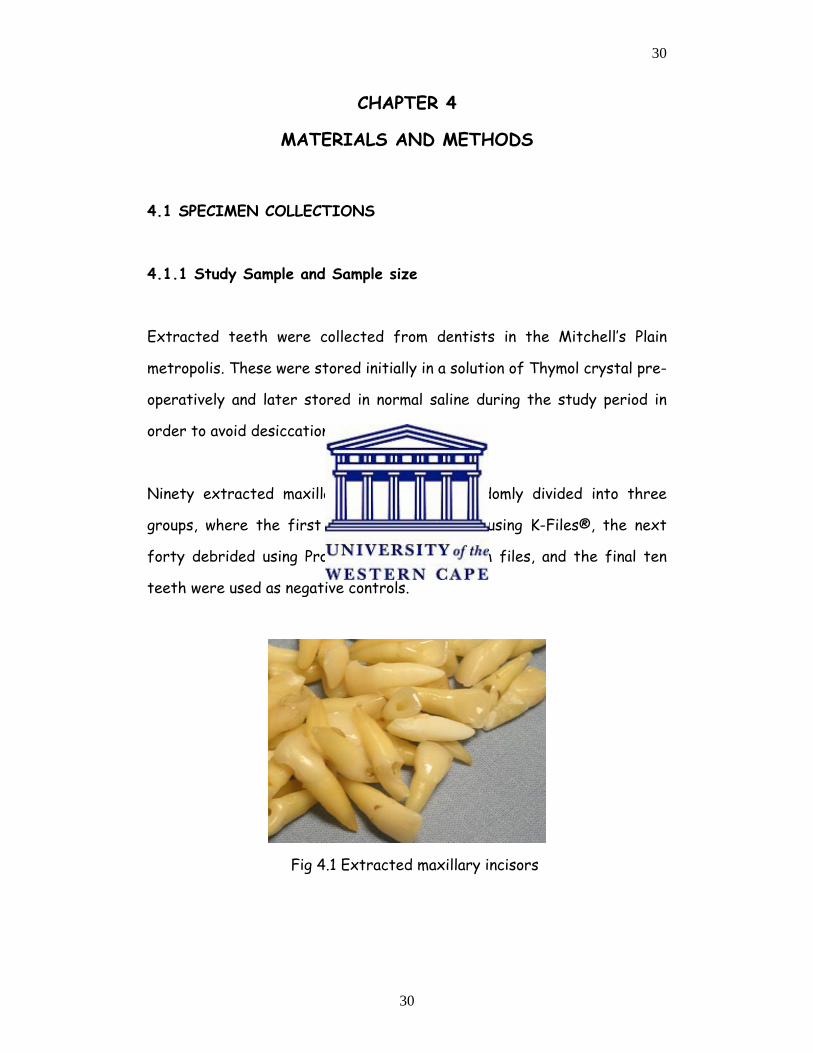
Ninety extracted maxillary incisors were randomly divided into three
groups, where the first forty were debrided using K-Files®, the next
forty debrided using ProTaper® nickel-titanium files, and the final ten
teeth were used as negative controls.
Fig 4.1 Extracted maxillary incisors
31
31
4.2 STUDY DESIGN
4.2.1 Design This was an in vitro descriptive study analyzing the efficacy of rotary and
manual debridement of root canals during simulated root canal therapy.
4.3 STUDY SAMPLE
4.3.1 Inclusion Criteria:
Anterior maxillary teeth of approximately 27millimetre in lengths were
collected from dental practitioners in the Mitchell’s Plain area and were
used in the study. The teeth had minimal dental caries and if caries was
present it did not encroach on the pulp, as observed both clinically and
radiographically. All teeth had intact crowns.
4.3.2 Exclusion Criteria:
• All teeth that showed the presence of calcification and sclerosis in
the pre-operative radiographs.
• Badly broken down carious teeth.
• Heavily restored teeth.
• Teeth with signs of resorption (internal or external resorption)
• Teeth showing the possible presence of hairline fractures.
4.4 PILOT STUDY
A pilot study was carried out using ten teeth from each group (rotary and
manual) and five control teeth that were debrided and studied using the
Scanning Electron Microscope to assess the feasibility of the study. This
pilot study was repeated in order to limit researcher bias and to check
the consistency of the results obtained. The samples were measured at a
1mm field at the most apical aspect of all segments under examination.
32
32
4.5 ETHICAL CONSIDERATION
4.5.1Teeth Collection
The teeth collected for this study were extracted for reasons other
than the purpose of this study, and were stored in accordance to the
specifications of this research project.
4.5.2 Teeth Disposal
On completion of the study the teeth were discarded in accordance
with the current medical waste disposal practice carried out at the
Dental faculty of the University of the Western Cape and these were
subsequently incinerated.
33
33
4.6 ENDODONTIC THERAPY
4.6.1 Endodontic therapy on specimens
The pulps of the ten control teeth were exposed (access cavity) on the
palatal aspect incisal to the cingulum. Medium barbed broaches were used
to extirpate the necrotic pulp tissues from the root canals and the teeth
were then stored in normal saline during the treatment phase. A
standardized pre-operative radiograph was obtained using a 25cm long
cone at a distance of 5cm for each tooth to measure the working length
(Facilitated by the use of a Rinn holder).
The eighty experimental teeth were also exposed (access cavities) and
barbed broaches were used to negotiate the root canals to remove the
necrotic pulp tissue. A solution of 0,5% sodium hypochlorite was used
copiously to irrigate the canals during debridement, followed by 5
millilitres of sterile saline solution after completion of debridement. The
canals were thoroughly dried with sterile paper points
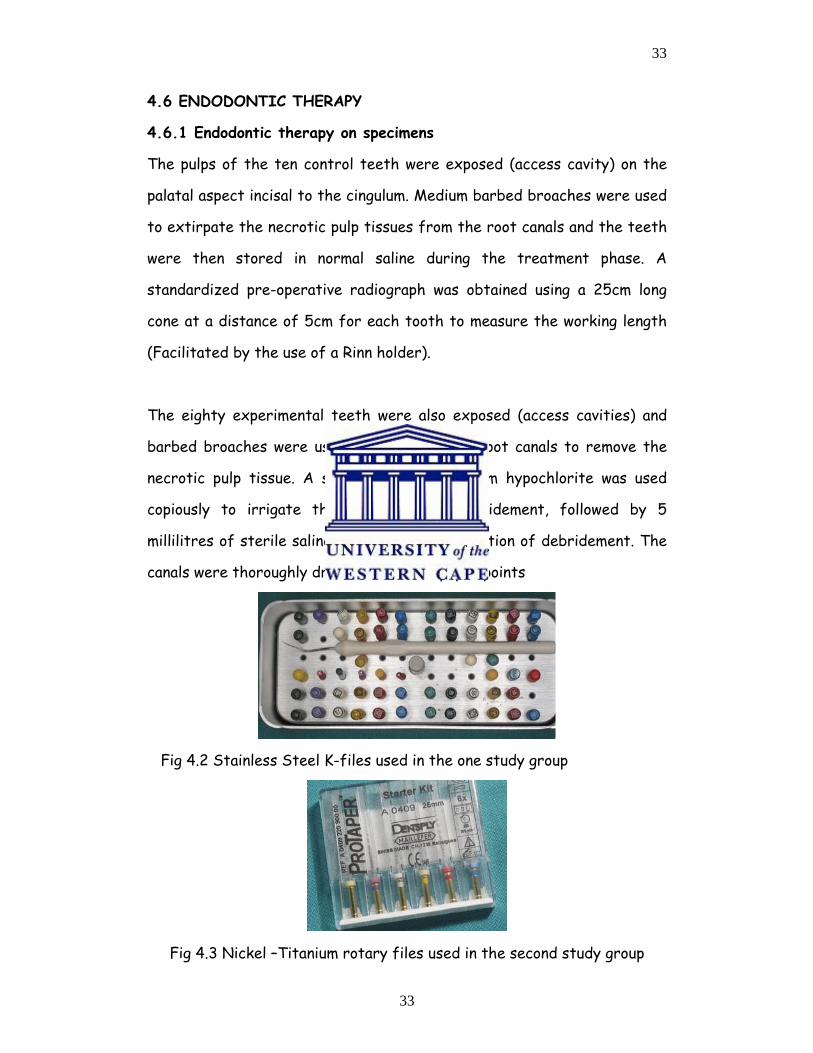
Fig 4.2 Stainless Steel K-files used in the one study group
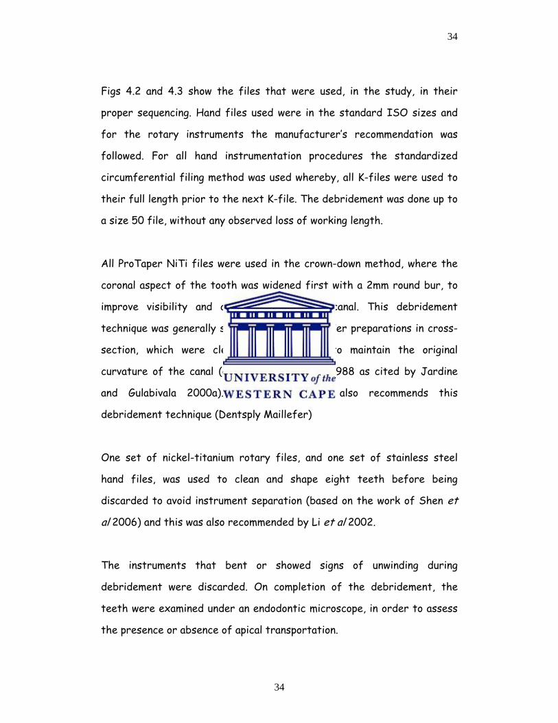
Fig 4.3 Nickel –Titanium rotary files used in the second study group
34
34
Figs 4.2 and 4.3 show the files that were used, in the study, in their
proper sequencing. Hand files used were in the standard ISO sizes and
for the rotary instruments the manufacturer’s recommendation was
followed. For all hand instrumentation procedures the standardized
circumferential filing method was used whereby, all K-files were used to
their full length prior to the next K-file. The debridement was done up to
a size 50 file, without any observed loss of working length.
All ProTaper NiTi files were used in the crown-down method, where the
coronal aspect of the tooth was widened first with a 2mm round bur, to
improve visibility and access to the root canal. This debridement
technique was generally shown to produce rounder preparations in cross-
section, which were cleaner and are said to maintain the original
curvature of the canal (Calhoun, Montgomery 1988 as cited by Jardine
and Gulabivala 2000a). The manufacturer also recommends this
debridement technique (Dentsply Maillefer)
One set of nickel-titanium rotary files, and one set of stainless steel
hand files, was used to clean and shape eight teeth before being
discarded to avoid instrument separation (based on the work of Shen et
al 2006) and this was also recommended by Li et al 2002.
The instruments that bent or showed signs of unwinding during
debridement were discarded. On completion of the debridement, the
teeth were examined under an endodontic microscope, in order to assess
the presence or absence of apical transportation.
35
35
All the experimental teeth were sectioned vertically in a mesio-distal
direction, using a diamond bur to a depth of 3mm, and finally splitting the
sections apart using a flat plastic hand instrument to avoid contamination
of the canals during the separation process (Jeon, Larz, Spangberg et al
2003, Ahlquist et al 2001). The root canal walls remained intact and
available for quantitative measurements at the apical, middle and coronal
thirds for smear layer and debris evaluation.
The apical 1mm of all three segments of the canal walls was examined
using the scanning electron microscope for debris and smear layer. The
apical third of the canal was also assessed for the amount and direction
of apical transportation, if any existed, using an endodontic microscope.
The quantitative measurement of smear layer was achieved by checking
tubular coverage, homogeneous smear layer or heterogeneously thick
smear layer covering the dentinal tubules.
The canal surfaces were classified at different levels with reference to
the amount of debris and smear layer. Scores ranging from one for clean
walls, and five for walls completely covered with smear layer were
recorded. As regards debris a score of slight debris, moderate (less than
50% of the surface covered) or substantial debris (more than 50% of
surface being covered) were recorded.
36
36
4.7 DEFINITIONS
1. Debris was defined as dentine chips, pulpal remnants, other
particles loosely stuck to the canal walls according to Hulsmann and
Stryga (1993)
2. Smear layer was defined as a film of debris attached to dentine
and other surfaces following instrumentation with rotary files or
manual endodontic files. It therefore consisted of dentine
particles, remnants from vital or necrotic pulp tissue, bacterial
products and retained rinsing fluid according to McComb, Smith
(1975)
4.8 SCORING OF SMEAR LAYER AND DEBRIS
4.8.1 SMEAR LAYER (According to Hulsmann and Stryga, 1993,
McComb and Smith 1975)
Score I: No smear layer, open dentinal tubules.
Score II: Slight smear layer, more dentinal tubules open than closed
Score III: Homogeneous smear layer covering major part of the surface,
Fewer dentinal tubules open than closed.
Score IV: Homogeneous smear layer covering the surface, no open
dentinal tubules
Score V: Thick non-homogenous smear layer covering the surface.
37
37
4.8.2 DEBRIS: (According to Hulsmann and Stryga, 1993, Ahlquist et
al 2001)
Score I: Clean root canal wall, very slight debris
Score II: Slight debris
Score III: Moderate amount of debris, less than 50% of the sample
Surface
Score IV: Substantial debris, more than 50% of the sample covered.
Score V: Complete coverage of the root canal wall by debris
38
38
4.9 SPECIMEN PREPARATION
4.9.1 Preparation of specimen for scanning electron microscope(SEM)
examination
The prepared specimens were placed in the desiccator for a period of
two days or forty-eight hours, to allow all moisture from the specimen
to escape under pressure. Conductive carbon adhesives were placed on
aluminium stubs to retain the specimen. These stubs were used to
transport the specimen into the SEM for evaluation.
The specimens on the aluminium stubs were first transferred to a
sputter coater in order that the specimens could be gold
plated/coated. The gold coating is an ionization process where the
argon gas is directed onto the gold plate on the machine, under
pressure, resulting in gold ion release and thereby coating the
specimen for observation, as seen in figs 4.4 and 4.5
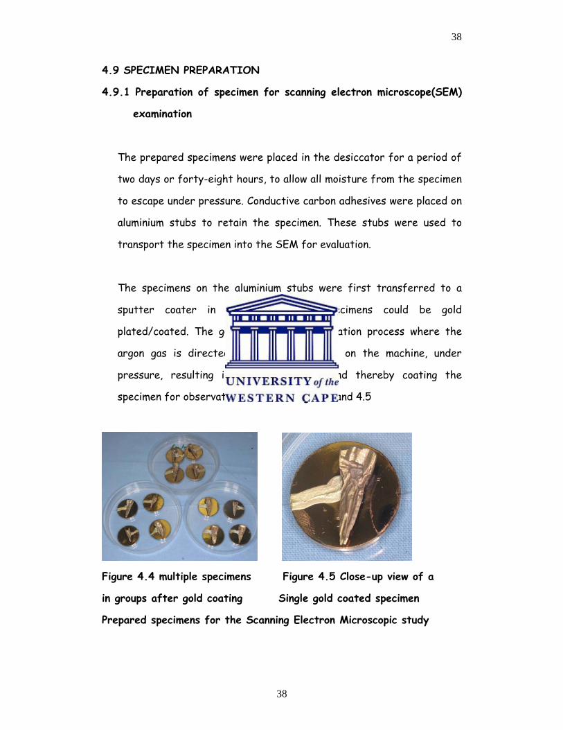
Figure 4.4 multiple specimens Figure 4.5 Close-up view of a
in groups after gold coating Single gold coated specimen
Prepared specimens for the Scanning Electron Microscopic study
39
39
The gold-coated specimens were maintained in their experimental groups
(figure 4.4). It took four minutes to completely coat a specimen.
4.8.2 Specimen preparation for scanning electron microscope
evaluation and image production.
• The image was displayed on a cathode ray tube, where the
specimen was bombarded with electrons generated by the electron
gun, releasing a primary electron (that did not generate the image).
These primary electrons then knocked the electrons from the
specimen. Secondary electrons were then released and the
detector collected these creating the viewed image.
• A vacuum has to be created before the shutter door of the SEM
can be opened (a vacuum is important for the prevention of
moisture contamination of the specimen).
• The image is then captured via an electronic digital camera and can
be displayed on the monitor. These images can be recorded either
on film or on computer disc.
40
40
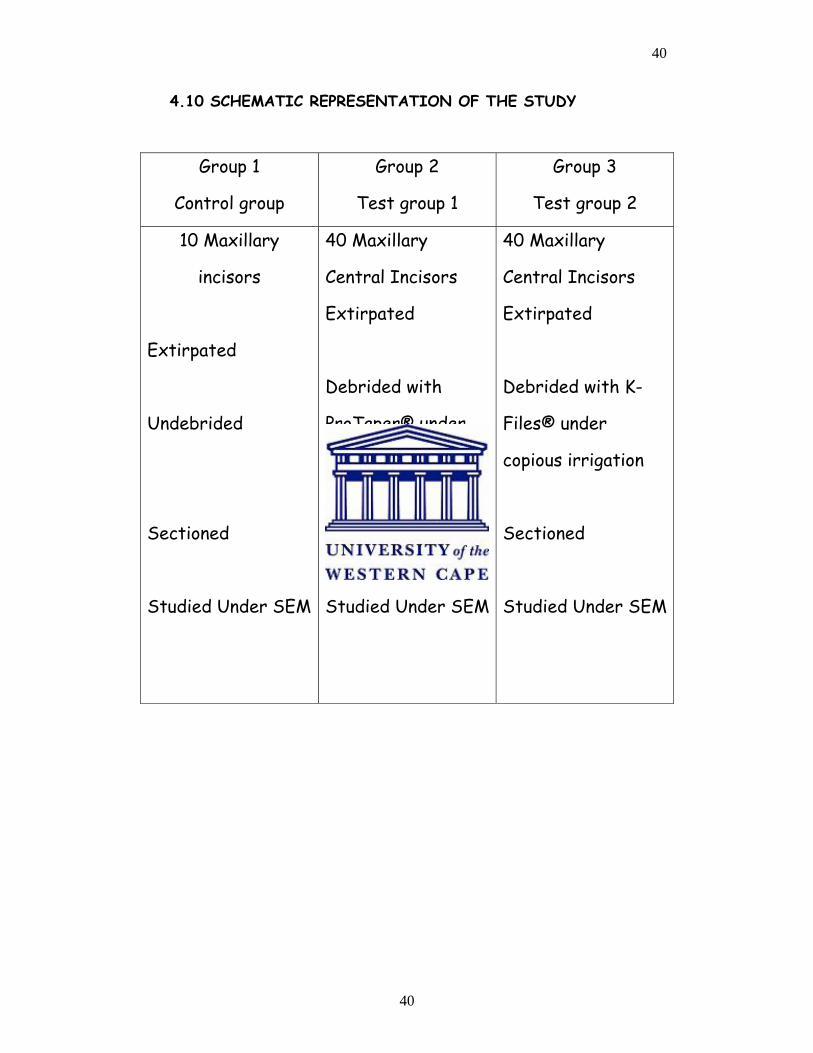
4.10 SCHEMATIC REPRESENTATION OF THE STUDY
Group 1
Control group
Group 2
Test group 1
Group 3
Test group 2
10 Maxillary
incisors
Extirpated
Undebrided
Sectioned
Studied Under SEM
40 Maxillary
Central Incisors
Extirpated
Debrided with
ProTaper® under
copious irrigation
Sectioned
Studied Under SEM
40 Maxillary
Central Incisors
Extirpated
Debrided with K-
Files® under
copious irrigation
Sectioned
Studied Under SEM
41
41
CHAPTER 5
RESULTS
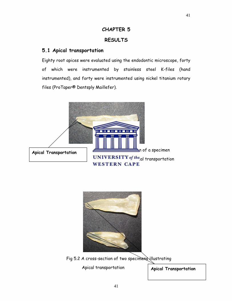
5.1 Apical transportation
Eighty root apices were evaluated using the endodontic microscope, forty
of which were instrumented by stainless steel K-files (hand
instrumented), and forty were instrumented using nickel titanium rotary
files (ProTaper® Dentsply Maillefer).
Fig 5.1 A cross-section of a specimen
illustrating api illustrating apical transportation
Fig 5.2 A cross-section of two specimens illustrating
Apical transportation
Apical Transportation
Apical Transportation
42
42
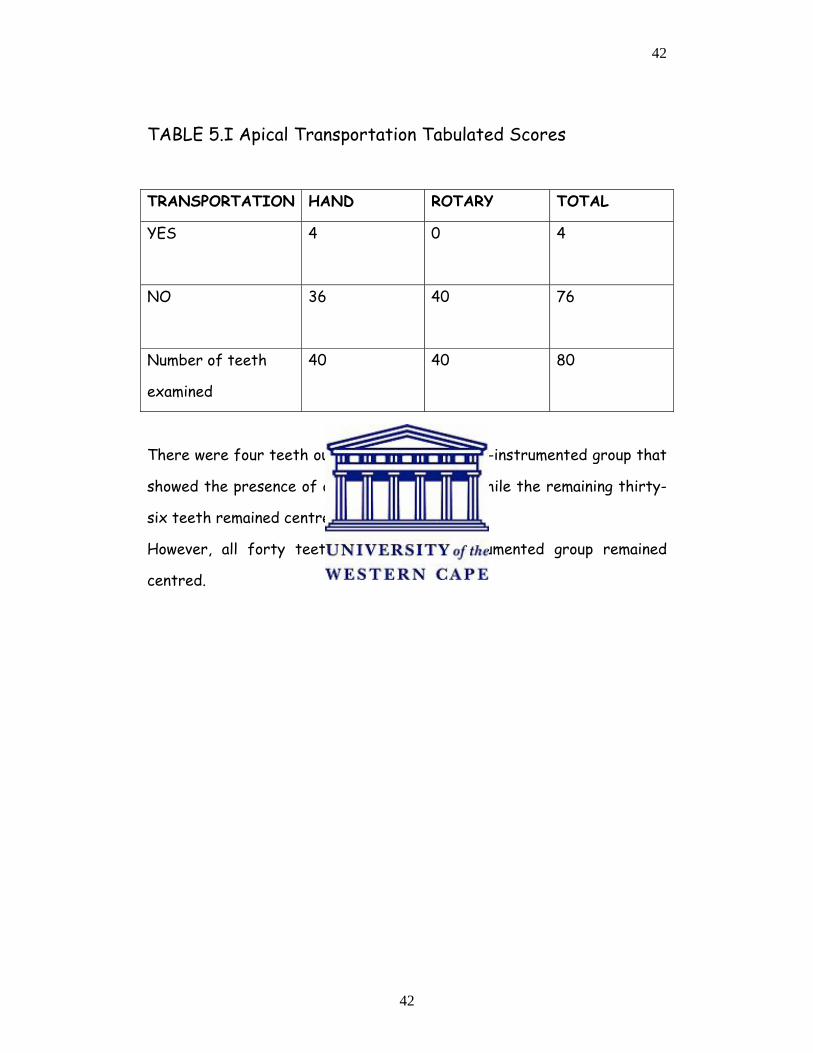
TABLE 5.I Apical Transportation Tabulated Scores
TRANSPORTATION HAND ROTARY TOTAL
YES
4 0 4
NO
36 40 76
Number of teeth
examined
40 40 80
There were four teeth out of forty, in the hand-instrumented group that
showed the presence of apical transportation while the remaining thirty-
six teeth remained centred.
However, all forty teeth in the rotary-instrumented group remained
centred.
43
43
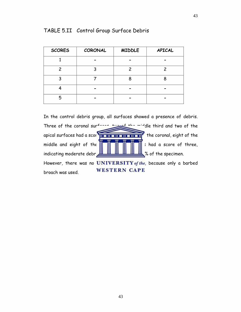
TABLE 5.II Control Group Surface Debris
SCORES CORONAL MIDDLE APICAL
1 - - -
2 3 2 2
3 7 8 8
4 - - -
5 - - -
In the control debris group, all surfaces showed a presence of debris.
Three of the coronal surfaces, two of the middle third and two of the
apical surfaces had a score of two while seven of the coronal, eight of the
middle and eight of the apical third surfaces had a score of three,
indicating moderate debris covering less than 50% of the specimen.
However, there was no smear layer formation, because only a barbed
broach was used.
44
44
SURFACE DEBRIS (Control)
3
2 2
7
8 8
0
1
2
3
4
5
6
7
8
9
CORONAL MIDDLE APICAL
Tooth Surfaces
Num
ber o
f Tee
th
Slight Deb (2)Moderate Deb (3)
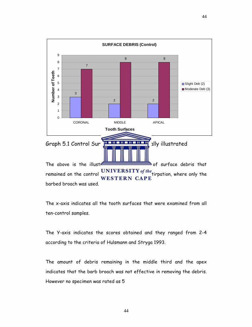
Graph 5.1 Control Surface Debris graphically illustrated
The above is the illustration of the amount of surface debris that
remained on the control teeth following only extirpation, where only the
barbed broach was used.
The x-axis indicates all the tooth surfaces that were examined from all
ten-control samples.
The Y-axis indicates the scores obtained and they ranged from 2-4
according to the criteria of Hulsmann and Stryga 1993.
The amount of debris remaining in the middle third and the apex
indicates that the barb broach was not effective in removing the debris.
However no specimen was rated as 5
45
45
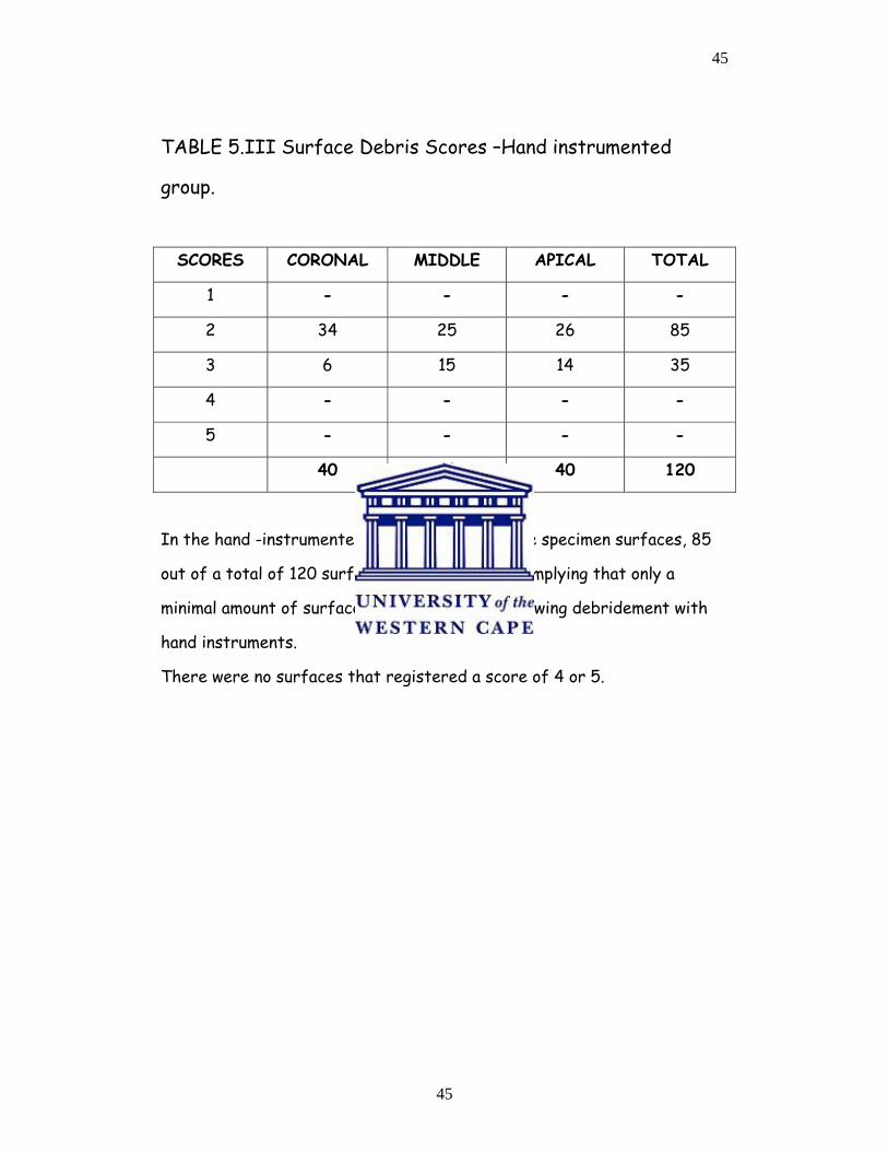
TABLE 5.III Surface Debris Scores –Hand instrumented
group.
SCORES CORONAL MIDDLE APICAL TOTAL
1 - - - -
2 34 25 26 85
3 6 15 14 35
4 - - - -
5 - - - -
40 40 40 120
In the hand -instrumented group, the bulk of the specimen surfaces, 85
out of a total of 120 surfaces had a score of 2, implying that only a
minimal amount of surface debris remained, following debridement with
hand instruments.
There were no surfaces that registered a score of 4 or 5.
46
46
SURFACE DEBRIS HAND INSTRUMENTATION
34
25 26
6
15 14
0
5
10
15
20
25
30
35
40
CORONAL MIDDLE APICAL
Tooth Surfaces
Num
ber o
f Tee
th
Slight Deb (2)Moderate Deb (3)
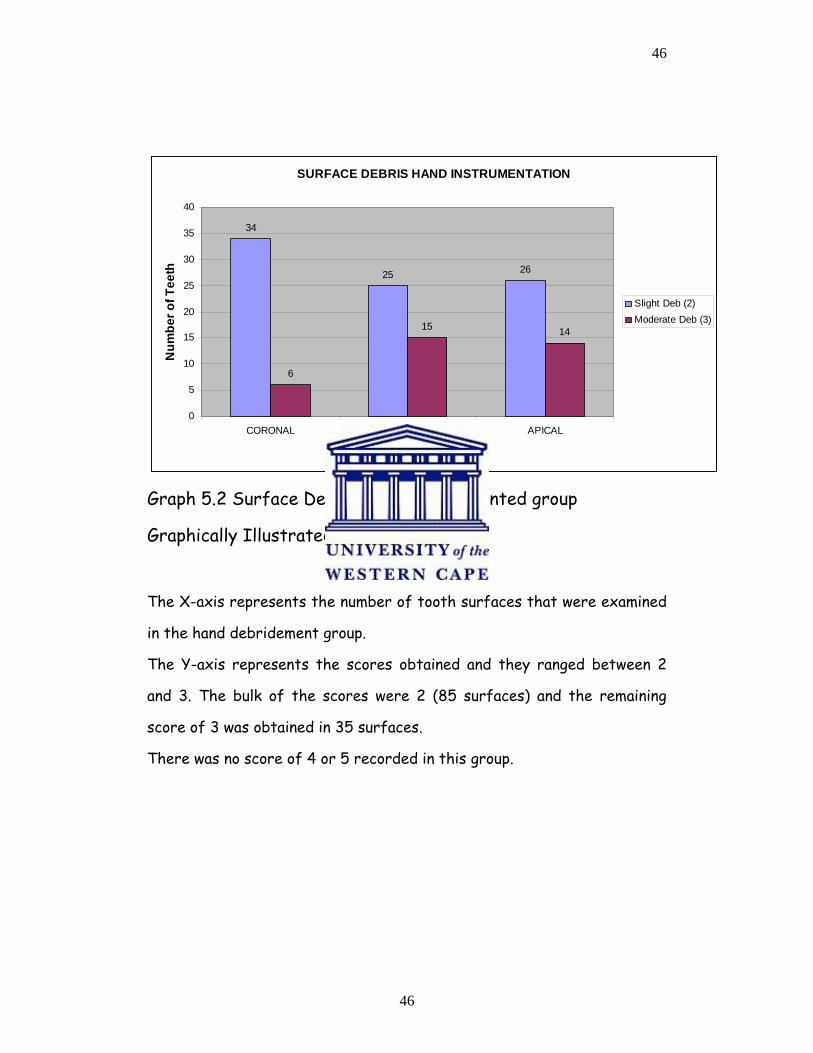
Graph 5.2 Surface Debris –Hand instrumented group
Graphically Illustrated
The X-axis represents the number of tooth surfaces that were examined
in the hand debridement group.
The Y-axis represents the scores obtained and they ranged between 2
and 3. The bulk of the scores were 2 (85 surfaces) and the remaining
score of 3 was obtained in 35 surfaces.
There was no score of 4 or 5 recorded in this group.
47
47
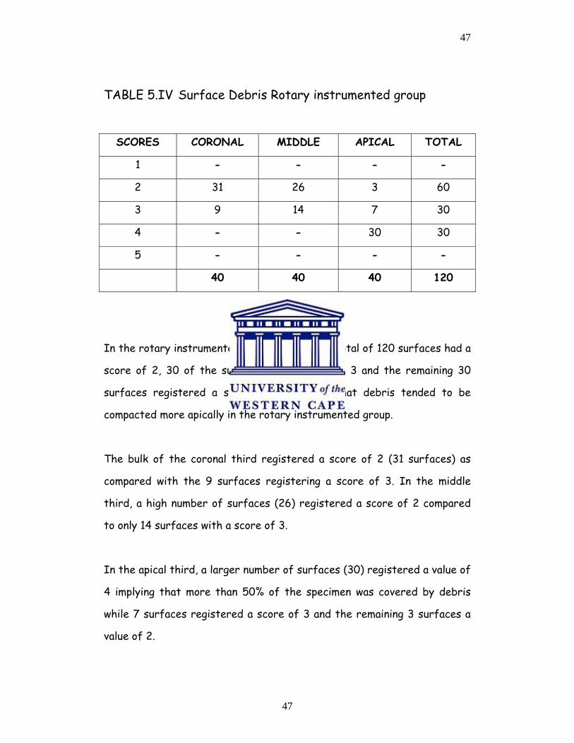
TABLE 5.IV Surface Debris Rotary instrumented group
SCORES CORONAL MIDDLE APICAL TOTAL
1 - - - -
2 31 26 3 60
3 9 14 7 30
4 - - 30 30
5 - - - -
40 40 40 120
In the rotary instrumented group, 60 out of a total of 120 surfaces had a
score of 2, 30 of the surfaces had a score of 3 and the remaining 30
surfaces registered a score of 4, implying that debris tended to be
compacted more apically in the rotary instrumented group.
The bulk of the coronal third registered a score of 2 (31 surfaces) as
compared with the 9 surfaces registering a score of 3. In the middle
third, a high number of surfaces (26) registered a score of 2 compared
to only 14 surfaces with a score of 3.
In the apical third, a larger number of surfaces (30) registered a value of
4 implying that more than 50% of the specimen was covered by debris
while 7 surfaces registered a score of 3 and the remaining 3 surfaces a
value of 2.
48
48
SURFACE DEBRIS ROTARY INSTRUMENTATION
31
26
3
9
14
7
30
0
5
10
15
20
25
30
35
CORONAL MIDDLE APICAL
Tooth Surfaces
Num
ber o
f Tee
th
Slight Deb (2)Moderate Deb (3)Substantial Deb (4)
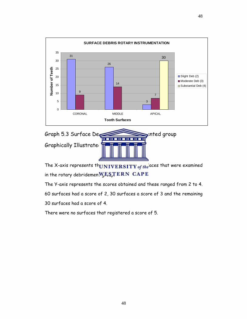
Graph 5.3 Surface Debris rotary instrumented group
Graphically Illustrated
The X-axis represents the number of tooth surfaces that were examined
in the rotary debridement group.
The Y-axis represents the scores obtained and these ranged from 2 to 4.
60 surfaces had a score of 2, 30 surfaces a score of 3 and the remaining
30 surfaces had a score of 4.
There were no surfaces that registered a score of 5.
49
49
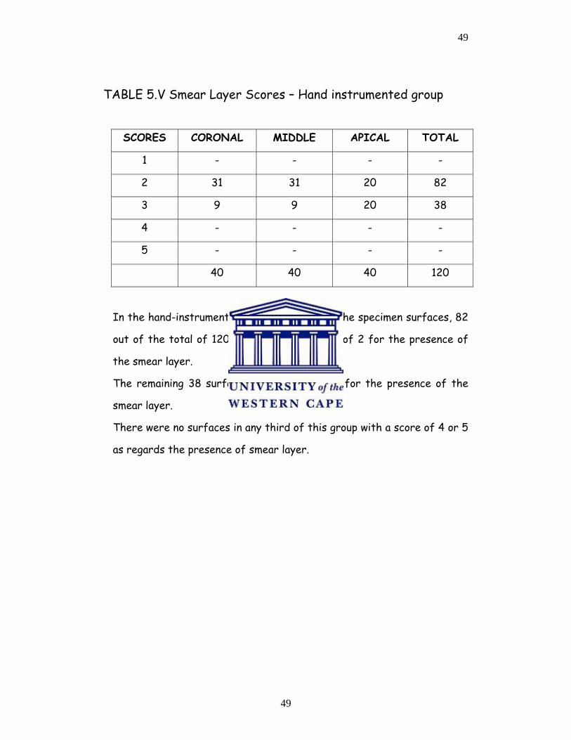
TABLE 5.V Smear Layer Scores – Hand instrumented group
SCORES CORONAL MIDDLE APICAL TOTAL
1 - - - -
2 31 31 20 82
3 9 9 20 38
4 - - - -
5 - - - -
40 40 40 120
In the hand-instrumented group, the bulk of the specimen surfaces, 82
out of the total of 120 surfaces had a score of 2 for the presence of
the smear layer.
The remaining 38 surfaces had a score of 3 for the presence of the
smear layer.
There were no surfaces in any third of this group with a score of 4 or 5
as regards the presence of smear layer.
50
50
SURFACE SMEAR LAYER HAND INSTRUMENTATION
31 31
20
9 9
20
0
5
10
15
20
25
30
35
CORONAL MIDDLE APICAL
Tooth Surfaces
Num
ber o
f Tee
th
Slight SL (2)Homogeneous SL (3)
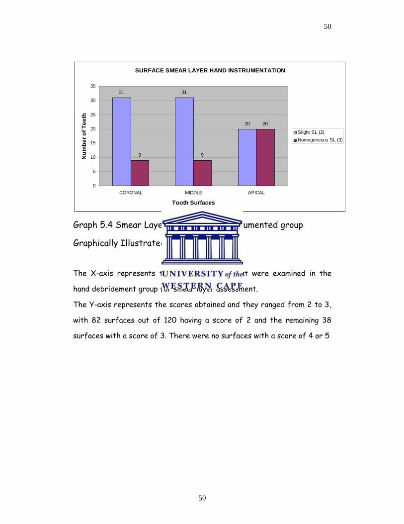
Graph 5.4 Smear Layer Scores Hand instrumented group
Graphically Illustrated
The X-axis represents the tooth surfaces that were examined in the
hand debridement group for smear layer assessment.
The Y-axis represents the scores obtained and they ranged from 2 to 3,
with 82 surfaces out of 120 having a score of 2 and the remaining 38
surfaces with a score of 3. There were no surfaces with a score of 4 or 5
51
51
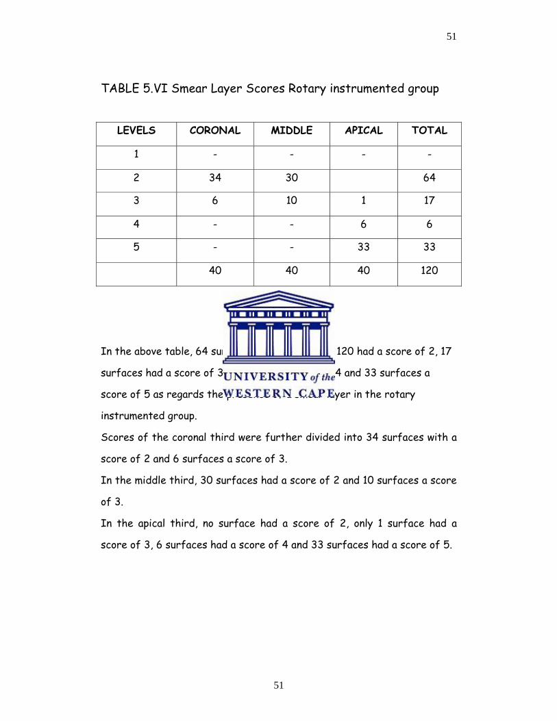
TABLE 5.VI Smear Layer Scores Rotary instrumented group
LEVELS CORONAL MIDDLE APICAL TOTAL
1 - - - -
2 34 30 64
3 6 10 1 17
4 - - 6 6
5 - - 33 33
40 40 40 120
In the above table, 64 surfaces out of a total of 120 had a score of 2, 17
surfaces had a score of 3, 6 surfaces a score of 4 and 33 surfaces a
score of 5 as regards the presence of a smear layer in the rotary
instrumented group.
Scores of the coronal third were further divided into 34 surfaces with a
score of 2 and 6 surfaces a score of 3.
In the middle third, 30 surfaces had a score of 2 and 10 surfaces a score
of 3.
In the apical third, no surface had a score of 2, only 1 surface had a
score of 3, 6 surfaces had a score of 4 and 33 surfaces had a score of 5.
52
52
SURFACE SMEAR LAYER ROTARY INSTRUMENTATION
34
30
0
6
10
10
5
10
15
20
25
30
35
40
CORONAL MIDDLE APICAL
Tooth Surfaces
Num
ber o
f Tee
th
Slight SL (2)Homogeneous SL (3)No Open Dentinal Tub (4)Non Homogeneous (5)
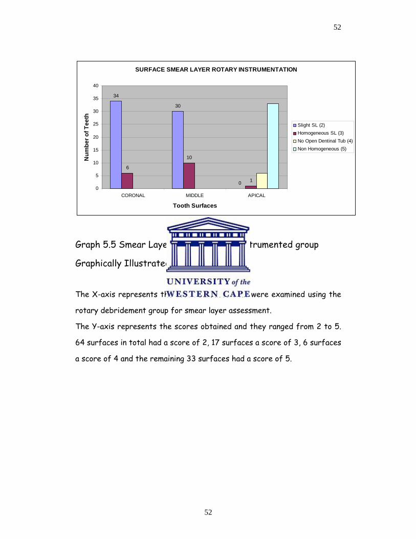
Graph 5.5 Smear Layer Scores Rotary instrumented group
Graphically Illustrated
The X-axis represents the tooth surfaces that were examined using the
rotary debridement group for smear layer assessment.
The Y-axis represents the scores obtained and they ranged from 2 to 5.
64 surfaces in total had a score of 2, 17 surfaces a score of 3, 6 surfaces
a score of 4 and the remaining 33 surfaces had a score of 5.
53
53
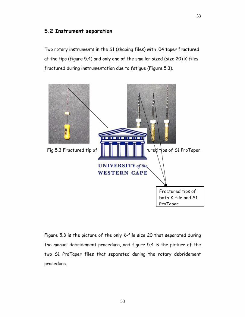
5.2 Instrument separation
Two rotary instruments in the S1 (shaping files) with .04 taper fractured
at the tips (figure 5.4) and only one of the smaller sized (size 20) K-files
fractured during instrumentation due to fatigue (Figure 5.3).
Fig 5.3 Fractured tip of K-File Fig 5.4 Fractured tips of S1 ProTaper
Figure 5.3 is the picture of the only K-file size 20 that separated during
the manual debridement procedure, and figure 5.4 is the picture of the
two S1 ProTaper files that separated during the rotary debridement
procedure.
Fractured tips of both K-file and S1 ProTaper
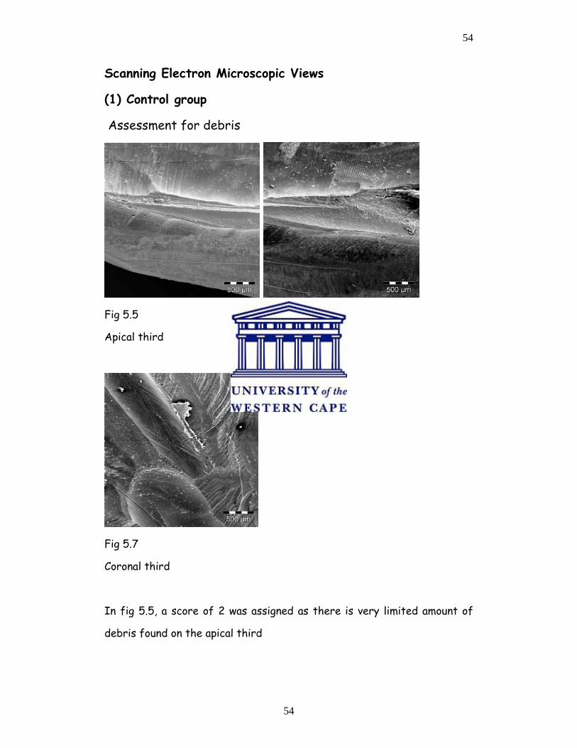
54
54
Scanning Electron Microscopic Views
(1) Control group
Assessment for debris
Fig 5.5 Fig 5.6
Apical third Middle third
Fig 5.7
Coronal third
In fig 5.5, a score of 2 was assigned as there is very limited amount of
debris found on the apical third

55
55
Fig 5.6 was assigned a score of 3, as the amount of debris does not cover
all the surfaces of the middle third of the root canal. On higher
magnification, more than 50% of the dentinal tubules could be
demonstrated.
Fig 5.7 was assigned a score of 3, as the nerve tissue was seen due to
larger areas which were uninstrumented. On higher magnification it was
shown than there were large interlacing areas with more that 50% of the
dentinal tubules clearly demonstrated, even in the presence of residual
nerve tissue.
Fig 5.8 X1000 Fig 5.9 X1000
Figures 5.8 and 5.9 have been included to show that the residual debris
did not occlude the dentinal tubules
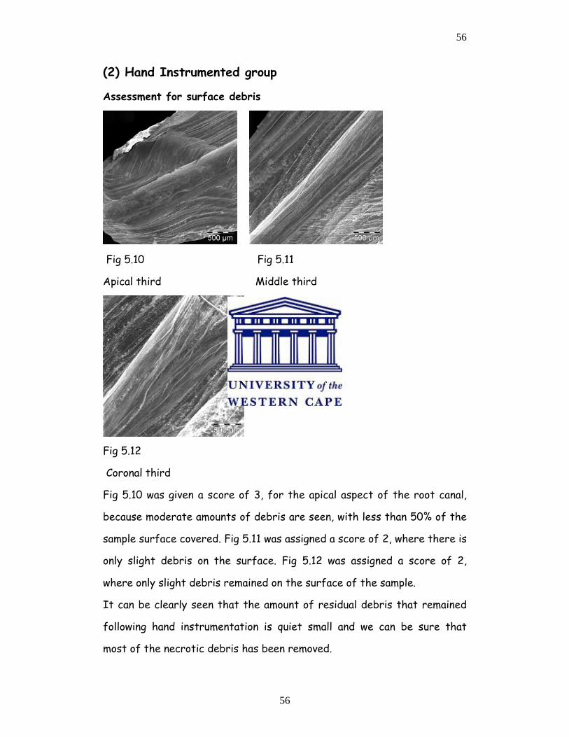
56
56
(2) Hand Instrumented group
Assessment for surface debris
Fig 5.10 Fig 5.11
Apical third Middle third
Fig 5.12
Coronal third
Fig 5.10 was given a score of 3, for the apical aspect of the root canal,
because moderate amounts of debris are seen, with less than 50% of the
sample surface covered. Fig 5.11 was assigned a score of 2, where there is
only slight debris on the surface. Fig 5.12 was assigned a score of 2,
where only slight debris remained on the surface of the sample.
It can be clearly seen that the amount of residual debris that remained
following hand instrumentation is quiet small and we can be sure that
most of the necrotic debris has been removed.
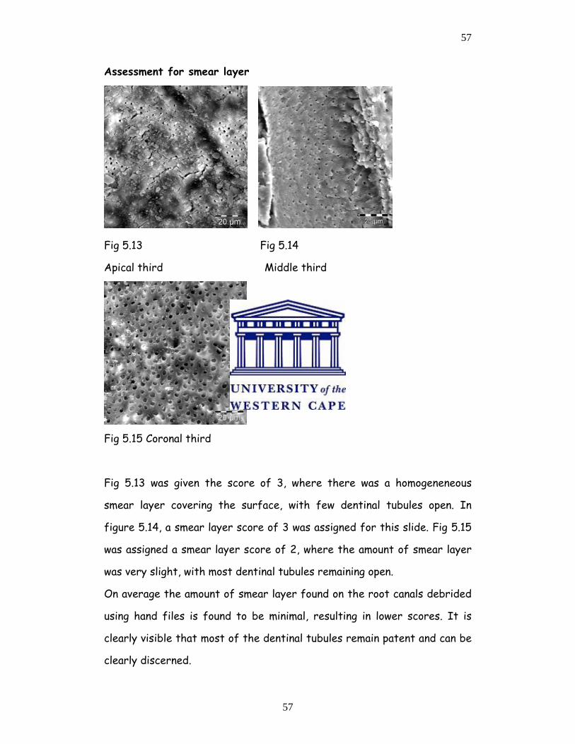
57
57
Assessment for smear layer
Fig 5.13 Fig 5.14
Apical third Middle third
Fig 5.15 Coronal third
Fig 5.13 was given the score of 3, where there was a homogeneneous
smear layer covering the surface, with few dentinal tubules open. In
figure 5.14, a smear layer score of 3 was assigned for this slide. Fig 5.15
was assigned a smear layer score of 2, where the amount of smear layer
was very slight, with most dentinal tubules remaining open.
On average the amount of smear layer found on the root canals debrided
using hand files is found to be minimal, resulting in lower scores. It is
clearly visible that most of the dentinal tubules remain patent and can be
clearly discerned.
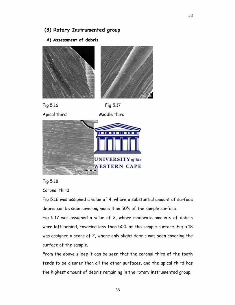
58
58
(3) Rotary Instrumented group
A) Assessment of debris
Fig 5.16 Fig 5.17
Apical third Middle third
Fig 5.18
Coronal third
Fig 5.16 was assigned a value of 4, where a substantial amount of surface
debris can be seen covering more than 50% of the sample surface.
Fig 5.17 was assigned a value of 3, where moderate amounts of debris
were left behind, covering less than 50% of the sample surface. Fig 5.18
was assigned a score of 2, where only slight debris was seen covering the
surface of the sample.
From the above slides it can be seen that the coronal third of the tooth
tends to be cleaner than all the other surfaces, and the apical third has
the highest amount of debris remaining in the rotary instrumented group.
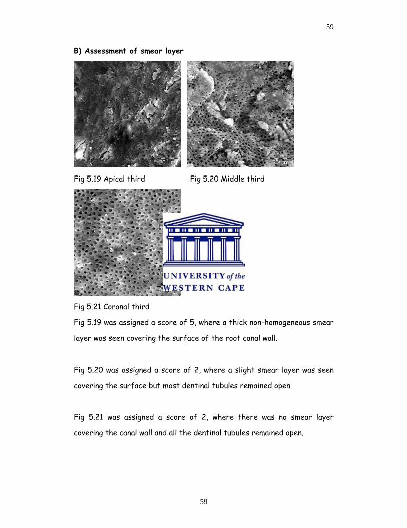
59
59
B) Assessment of smear layer
Fig 5.19 Apical third Fig 5.20 Middle third
Fig 5.21 Coronal third
Fig 5.19 was assigned a score of 5, where a thick non-homogeneous smear
layer was seen covering the surface of the root canal wall.
Fig 5.20 was assigned a score of 2, where a slight smear layer was seen
covering the surface but most dentinal tubules remained open.
Fig 5.21 was assigned a score of 2, where there was no smear layer
covering the canal wall and all the dentinal tubules remained open.
60
60
CHAPTER 6
DISCUSSION
The scanning electron microscopic study analysis seem to be an adequate
method used to investigate the influence of endodontic instruments on
the morphology of dentine surfaces, therefore the methodology employed
in the present study is in line with previous investigators (Ahlquist et al
2001).
Maintenance of the original canal as far as possible is a pre-requisite
during root canal preparation; so that, iatrogenic complications arising
from cleaning and shaping can be avoided. Results obtained in the present
study, indicate that there were only 4 teeth (10%) that showed signs of
apical transportation. All these teeth were from the hand-instrumented
samples.
These procedural errors of apical transportation and loss of working
length were only associated with the use of stainless steel hand files and
could be attributed to insufficient flexibility in the instruments. Tan and
Messer 2002, reported similar results, whereby two sites in twenty
locations (10%) examined exhibited canal transportation.
They found that more canal transportation occurred in the apical 1mm
level than at the 3mm level away from the apical foramen of hand
instrumented specimens, especially when the step back technique was
employed.
61
61
Iqbal et al 2003 demonstrated that different instrumentation sequences
used with nickel titanium rotary instruments produced similar results with
minimal apical transportation and loss of working length. Similarly, the
amount of apical transportation noticed in the present study corresponds
with the study conducted by Bryant et al 1998.
However, in the present study, an endodontic microscope was used to
evaluate the presence of apical transportation instead of radiographs
used in all the other studies. As expected, all sample teeth in the rotary-
instrumented group were found to have remained centred during the
preparations, while the 10% in the hand instrumented group that showed
apical transportation would have made making complete obturation
impossible in the clinical context.
These results correspond to those reported by other researchers such as
Iqbal et al 2003, Jardine and Gulabivala 2000(a), Tan and Messer 2002,
Sonntag, Delschen, Stachniss 2003.
In the study by Jardine and Gulabivala 2000(a), they suggested that the
reason nickel titanium instruments cause less transportation than
stainless steel K-files, when the same filing technique was used, may not
only be due to the increased flexibility of the nickel titanium
instruments, but rather to their decreased cutting ability.
They also noted that the curvature of the canal did not affect the
outcome of the efficacy of both hand and rotary instruments and that
the curvature of the root canals was maintained in all groups under
investigation, that is, there was no visible canal transportation in all the
62
62
groups that they examined. However, rotary nickel titanium files
separated in the presence of acute curves in root canal topography or
shape. Overall, the minor straightening or apical transportation that was
observed in the present study is comparable with other investigations.
Two files in the S1 or shaping range of the ProTaper® nickel titanium
rotary files separated and only one size 20 stainless steel K-file
separated. This was in line with results found by several investigators. Li
et al 2002, found that rotary instruments were susceptible to fracture
especially the shapers, because they are more rigid and are therefore not
able to engage curved canals without strain and distortion.
Shen et al 2006 also found that defects and distortions occurred with
rotary files. They found that these defects occurred on ProTaper® files
and the minimum number of times that these instruments can be safely
used is related to the anatomy and the morphology of the treated tooth.
In a study conducted by Schafer et al 2006, they found that during the
preparation of 120 teeth, a total of 10 instruments (12%) separated
probably as a result of instrument fatigue. It is therefore imperative
that the operator should inspect each and every instrument prior to
clinical use
In the study conducted by Schafer and Vlassis 2004, two ProTaper and
three RaCe instruments out of ten sets fractured, similar to the findings
in the present study.
63
63
In the study by Foschi et al 2004, the amount and the morphology of the
smear layer, presence of pulpal and dentinal debris and the morphology of
the inner dentinal walls were parameters they used for the evaluation of
shaping and cleaning efficacy of rotary nickel titanium instruments.
According to Torabinejad et al 2002, all endodontic instrumentations
create dentine debris and smear layer as a consequence of their action on
root canal walls. They indicated that the so formed debris might be
compacted along the entire root canal surface, thus increasing the risk
for bacterial contamination with subsequent reduction in the adaptation
of the sealer and Gutta-Percha.
Iqbal et al 2003, said that this debris might be compacted apically
creating an apical plug that prevents complete filling of this important
region. It was also noted that it was very important that endodontic
instruments remove dentine and debris from all canal walls, rendering the
walls free from any bacteria.
However, from the results obtained in the present study, it was shown
that the apical aspect of all root canals especially those debrided using
rotary instruments had large amounts of both debris and smear layer.
The results in table 5.II imply that by using only the barbed broach for
the extirpation, a large amount of debris still remained in the middle and
the apical thirds of the canal. In 80% of the specimen examined in this
group and therefore this in no way can be the only method of
debridement.
64
64
From table 5.III it is evident that between 35% and 49% of the canals in
this group still had debris classified as moderate (score 3) in the middle
and apical thirds of the canals and this would have impacted on the
clinical success if only this method of debridement was used.
From table 5.IV, it is apparent that substantial debris (score 4) was
present in the apical third of 75% of the canals debrided with the rotary
technique implying that this method on its own is not very efficient in
debriding the canal especially in the apical third of the root canal.
Figure 5.V illustrates that at least half the canals (50%) in the hand-
instrumented group had a homogeneous smear layer (score 3) still present
in the apical third of the canal and this will negatively impact on bonding
and sealing of the root canal especially in the apical third.
From table 5.VI it is apparent that in this rotary-instrumented group the
majority of the canals (82.5%) had a thick homogeneous smear layer
covering the dentine surfaces (score 5) in the apical third of the canals
and would make it difficult clinically to obtain a hermetic seal especially in
this part of the root canal.
It can be clearly seen that the use of rotary instruments resulted in the
formation of a large quantity of both smear layer and debris, as indicated
by the high scores recorded
Scanning electron microscopic analysis demonstrated a substantial portion
of the dentine surface in the coronal third to be free from smear layer.
This corresponds to the findings of Ahlquist et al 2001. However the
65
65
SEM findings in the apical third of the canals instrumented with rotary
instruments corresponds with previous scanning electron microscopic
(SEM) studies by Ahlquist et al 2001, Schafer and Lohmann 2002,
Versumer et al 2002, who also reported the presence of great amounts of
smear layer after the use of nickel titanium rotary and stainless steel
manual instruments in the apical third of the root canals.
It is likely that the nickel titanium rotary instruments produced fine
dentine particles and shavings that were spread out and compacted along
the dentine wall. Schafer et al 2006(b) concluded that the use of nickel
titanium rotary files produced a clean and debris free dentine surface in
the middle and coronal thirds; however, they were unable to produce a
dentine surface free from smear layer and debris in the apical third of
the root canal instrumented.
The reason for this difference in the debris-removal capability of these
rotary instruments especially in the apical third but also in the rest of
the root canal is probably due to the fact that the final apical
preparation diameter of the ProTaper group of instruments was the size
30. It has been shown by Hulsmann et al 2003, that larger apical
preparation sizes are necessary in many cases in order to contact as much
of the circumference of the root canal as possible in the apical third of
the canals to ensure optimal debridement in this critical area of the root
canal
According to Ahlquist et al 2001, significantly less debris was found in
the apical region when using the manual filing technique. This was found to
correspond with the results of the present study. They (Ahlquist et al
66
66
2001) concluded that the manual technique employed in their study
produced cleaner root canal walls than the rotary ProTaper® technique
probably due to the tactile feel and the experience of the operator.
However, neither of the instrumentation techniques achieved total
debridement of the root canal, with both debris and smear layer
remaining on the dentinal walls of the canals especially in the apical third
of the root canals. This was also found to be true in the present study.
In the present investigation, the two rotary instruments fractured
occurred with instrument size 30 or S1 tip, and only one size 20 K-file as
a result of fatigue. These results are in accordance with a previous study
(Guelzow et al 2005), where the incidence of fractures was avoided with
increasing file sizes, and with most fractures occurring with sizes 30 and
35.
AS regards the cleanliness of the canals these findings are in contrast
with the regularly held belief, that because the apex is narrower, and
the files should be engaging all the surfaces of the canal during
debridement, this region should be the cleanest. However, the results
obtained in this study corroborate with all the other studies conducted
and show that the apical third is the least instrumented of all the areas
of the root canal especially when using rotary instrumentation.
The weakness of the present study was that the SEM measurements for
debris and smear layer were arbitrary as no standardization is available
at this stage. The drying process resulted in crack formation; the badly
cracked specimens could thus not be used. Only two teeth showed severe
67
67
numbers of cracks and these were then discarded and replaced by two
new slides. The sources of these cracks could not be clearly determined
because the collection of the samples (teeth) was not standardized. The
researcher did not specify to the dentists that the patient’s ages should
have been noted. It would have made the results more predictable if, for
instance, the dentists were asked to collect teeth in the age group of
patients between 20 and 30 years of age, which would have meant that
the teeth would have been fairly young.
It could therefore not be ascertained with certainty what the main
cause of the cracks was, whether the cracks were present preoperatively,
during the experimentation or as a result of the drying process for SEM
analysis. Also the reason for tooth loss was not determined; therefore
the possibility of traumatic fracture could not be excluded.
The preoperative storage of these teeth was not specified in relation to
the time required to place the extracted teeth in normal saline, where
slight drying might have occurred if the practitioners delayed placing
these teeth in the storage jars provided. The observed cracks resulted in
the distortion in the smear layer, probably due to the shrinkage that took
place during the drying process.
Ahlquist et al 2001, also used the desiccator for the drying of their
specimens but they used platinum for specimen coating, however, Foschi
et al 2004 used critical point drying for their specimens prior to gold
sputter coating and these are alternatives that could be considered in
future studies using SEM analysis
68
68
Using higher magnification such as those used in figures 5.15 and
5.16(X1000) tended to zone in on a small area, thus limiting the size of
the surface area being analysed but provided detailed information as
regards the canal wall status and the patency of the dentinal tubules.
However this magnified view could not be used for debris and amount of
smear layer analysis as it was too limited a portion of the canal wall.
In the present investigation, most of the instrument fracture occurred at
the tips but these could be retrieved.
The amount of smear layer that remains after instrumenting with rotary
instruments is larger when compared to that remaining in the hand
instrumented samples.
In the present study, EDTA was not used because the aim of the study
was to assess the clinical efficacy of two instrumentation methods.
However, it is known that the use of EDTA removes most of the formed
smear layer thus exposing the dentinal tubules as demonstrated by a
study carried out by Ahlquist et al 2001. The application of EDTA is
known to improve the adhesion of root canal sealers for final obturation.
69
69
CHAPTER 7
LIMITATIONS
The following limitations were identified in the present study.
• Cracking of teeth during the specimen preparation, and the
aetiology of such cracks could not be established, as they could
have occurred pre-operatively, during the debridement, as a result
of the storage conditions, or during the drying process for SEM
analysis.
• There is a narrow margin between the first two scores in the
assessment of surface debris. There were no surfaces, which were
completely debris free, however the amount varied slightly,
therefore, to differentiate between a score of 1 and 2 was
impossible and these should in future be combined into one score.
• All samples were first measured or studied using both low
magnification (40) and higher magnification (1000). At lower
magnification, all sites chosen were 1mm on the apical aspect of all
the specimens. However, the higher magnification, tended to zoom
in on a small or narrow field of study, thus limiting the correct
assessment of root canal cleanliness as regards quantitative
analysis but was very valuable for qualitative assessment of the
canal walls and the patency of the dentinal tubules.
• The ProTaper files sequence is limited as compared to the K-files,
where debridement was continued up to file size 50 and only a size
30 was used to reach the apex when using ProTaper.
70
70
CHAPTER 8
CONCLUSIONS AND RECOMMENDATIONS
8.1 CONCLUSIONS
Within the parameters of this study, it can be concluded that both hand
instrumented and rotary-instrumented canals had evidence of debris and
smear layer after debridement especially in the apical third of the canals.
However hand instrumentation using K-files resulted in better cleanliness
of the root canal compared to rotary instrumentation using ProTaper
instruments. Both types of instrumentation techniques resulted in limited
amounts of instrument separation and need to be carried out with care.
ProTaper maintained the shape of the root canal more effectively
compared to hand instruments that resulted in 10% of the canals showing
evidence of apical transportation.
8.2 RECOMMENDATIONS
Based on the results of this study
• Care must be taken when using rotary or hand instruments for
canal debridement to avoid the possibility of instrument
separation
• Rotary instruments should not be used more than six times and
must be diligently examined prior to utilization for signs of
distortion, which can result in instrument separation.
• The results of this study show that neither hand instrumentation
nor rotary instrumentation methods resulted in all areas of the
71
71
root canal which were completely clean and therefore the need
for chemical debridement in addition to mechanical debridement
to better prepare the canal for the obturation process.
• In the event of SEM analysis, critical point drying of specimen
which is a completely controlled drying mechanism, instead of
placing the samples in the desiccator to dry over a 48 hour period
before sputter coating for SEM observations is recommended
because some samples showed varying degrees of crack formation
which cannot be accounted for and the specimens were therefore
excluded from the present study.
72
72
APPENDIX I
DEBRIS
TOOTH CORONAL MIDDLE APICAL
1 Control 1 3 2 4
2 Control 2 3 3 4
3 Control 3 3 3 3
4 Control 4 2 3 4
5 Control 5 2 3 4
6 Control 6 2 3 2
7 Control 7 3 3 2
8. Control 8 3 3 4
9 Control 9 3 3 4
10 Control 10 3 2 4
11 Hand 1 2 2 2
12 Hand 2 2 2 2
13 Hand 3 3 2 3
14 Hand 4 3 2 3
15 Hand 5 2 2 3
16 Hand 6 3 2 2
17 Hand 7 2 2 3
18 Hand 8 2 2 3
19 Hand 9 2 2 3
20 Hand 10 2 2 3
21 Hand 11 2 2 3
22 Hand 12 2 2 3
73
73
23 Hand 13 3 2 3
24 Hand 14 3 2 3
25 Hand 15 3 2 3
26 Hand 16 2 2 2
27 Hand 17 2 2 3
28 Hand 18 2 2 3
29 Hand 19 2 2 2
30 Hand 20 2 2 2
31 Hand 21 2 2 2
32 Hand 22 2 2 2
33 Hand 23 2 2 2
34 Hand 24 2 2 2
35 Hand 25 2 2 2
36 Hand 26 2 2 2
37 Hand 27 2 2 2
38 Hand 28 2 2 2
39 Hand 29 2 2 2
40 Hand 30 2 2 2
41 Hand 31 2 2 2
42 Hand 32 2 2 2
43 Hand 33 2 2 2
44 Hand 34 2 2 2
45 Hand 35 2 2 2
46 Hand 36 2 2 2
47 Hand 37 2 2 2
48 Hand 38 2 2 2
49 Hand 39 2 2 2
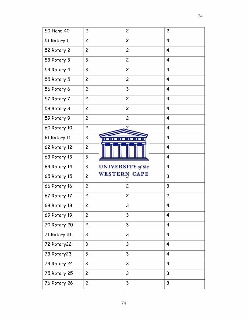
74
74
50 Hand 40 2 2 2
51 Rotary 1 2 2 4
52 Rotary 2 2 2 4
53 Rotary 3 3 2 4
54 Rotary 4 3 2 4
55 Rotary 5 2 2 4
56 Rotary 6 2 3 4
57 Rotary 7 2 2 4
58 Rotary 8 2 2 4
59 Rotary 9 2 2 4
60 Rotary 10 2 2 4
61 Rotary 11 3 2 4
62 Rotary 12 2 2 4
63 Rotary 13 3 3 4
64 Rotary 14 3 3 4
65 Rotary 15 2 3 3
66 Rotary 16 2 2 3
67 Rotary 17 2 2 2
68 Rotary 18 2 3 4
69 Rotary 19 2 3 4
70 Rotary 20 2 3 4
71 Rotary 21 3 3 4
72 Rotary22 3 3 4
73 Rotary23 3 3 4
74 Rotary 24 3 3 4
75 Rotary 25 2 3 3
76 Rotary 26 2 3 3
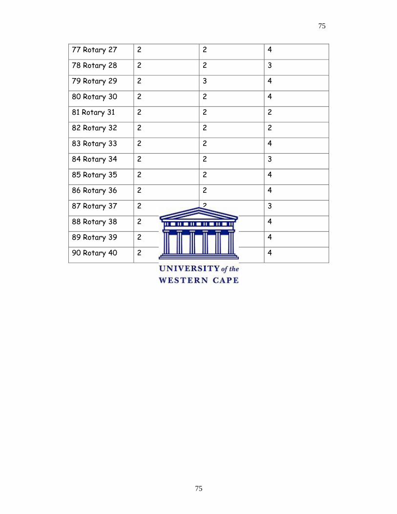
75
75
77 Rotary 27 2 2 4
78 Rotary 28 2 2 3
79 Rotary 29 2 3 4
80 Rotary 30 2 2 4
81 Rotary 31 2 2 2
82 Rotary 32 2 2 2
83 Rotary 33 2 2 4
84 Rotary 34 2 2 3
85 Rotary 35 2 2 4
86 Rotary 36 2 2 4
87 Rotary 37 2 2 3
88 Rotary 38 2 2 4
89 Rotary 39 2 2 4
90 Rotary 40 2 2 4
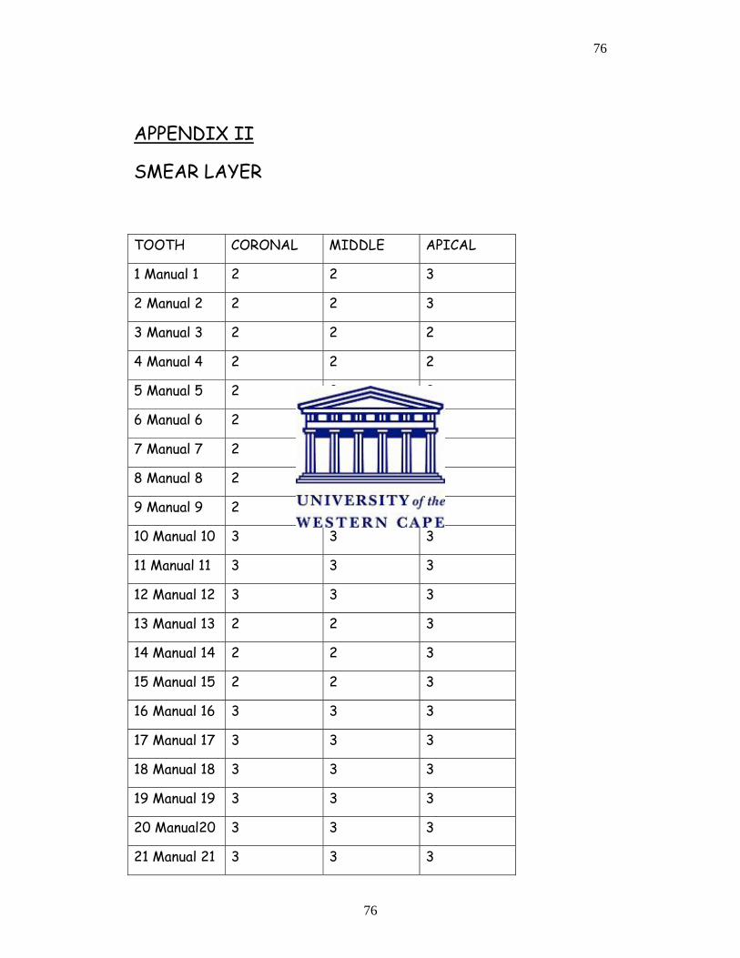
76
76
APPENDIX II
SMEAR LAYER
TOOTH CORONAL MIDDLE APICAL
1 Manual 1 2 2 3
2 Manual 2 2 2 3
3 Manual 3 2 2 2
4 Manual 4 2 2 2
5 Manual 5 2 2 2
6 Manual 6 2 2 3
7 Manual 7 2 2 3
8 Manual 8 2 2 3
9 Manual 9 2 2 2
10 Manual 10 3 3 3
11 Manual 11 3 3 3
12 Manual 12 3 3 3
13 Manual 13 2 2 3
14 Manual 14 2 2 3
15 Manual 15 2 2 3
16 Manual 16 3 3 3
17 Manual 17 3 3 3
18 Manual 18 3 3 3
19 Manual 19 3 3 3
20 Manual20 3 3 3
21 Manual 21 3 3 3
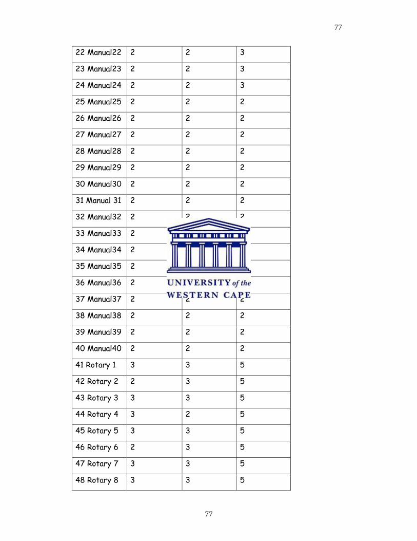
77
77
22 Manual22 2 2 3
23 Manual23 2 2 3
24 Manual24 2 2 3
25 Manual25 2 2 2
26 Manual26 2 2 2
27 Manual27 2 2 2
28 Manual28 2 2 2
29 Manual29 2 2 2
30 Manual30 2 2 2
31 Manual 31 2 2 2
32 Manual32 2 2 2
33 Manual33 2 2 2
34 Manual34 2 2 2
35 Manual35 2 2 2
36 Manual36 2 2 2
37 Manual37 2 2 2
38 Manual38 2 2 2
39 Manual39 2 2 2
40 Manual40 2 2 2
41 Rotary 1 3 3 5
42 Rotary 2 2 3 5
43 Rotary 3 3 3 5
44 Rotary 4 3 2 5
45 Rotary 5 3 3 5
46 Rotary 6 2 3 5
47 Rotary 7 3 3 5
48 Rotary 8 3 3 5
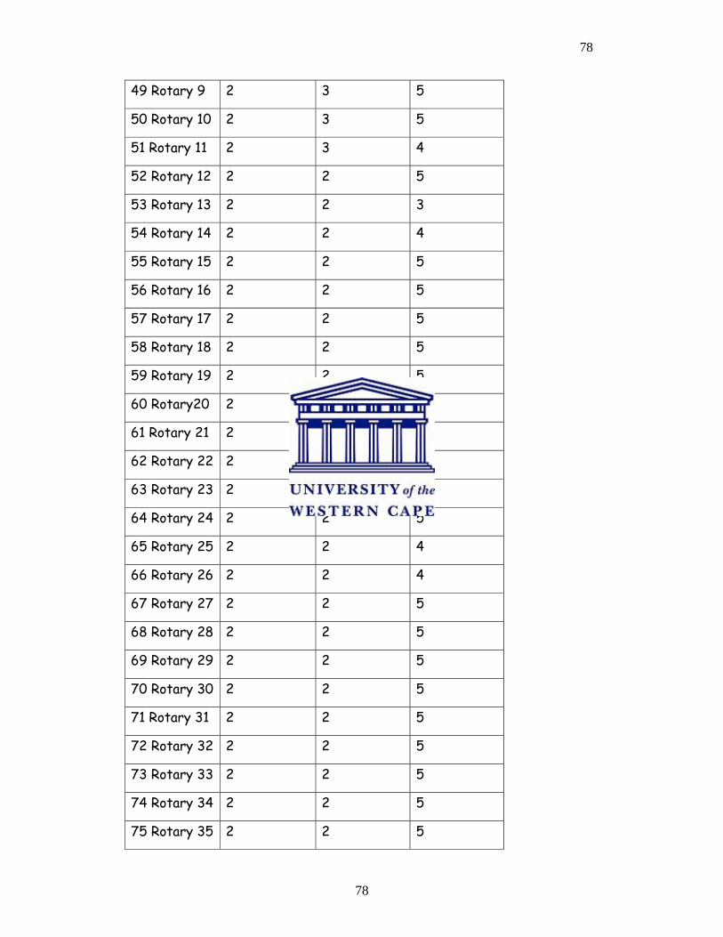
78
78
49 Rotary 9 2 3 5
50 Rotary 10 2 3 5
51 Rotary 11 2 3 4
52 Rotary 12 2 2 5
53 Rotary 13 2 2 3
54 Rotary 14 2 2 4
55 Rotary 15 2 2 5
56 Rotary 16 2 2 5
57 Rotary 17 2 2 5
58 Rotary 18 2 2 5
59 Rotary 19 2 2 5
60 Rotary20 2 2 5
61 Rotary 21 2 2 5
62 Rotary 22 2 2 5
63 Rotary 23 2 2 5
64 Rotary 24 2 2 5
65 Rotary 25 2 2 4
66 Rotary 26 2 2 4
67 Rotary 27 2 2 5
68 Rotary 28 2 2 5
69 Rotary 29 2 2 5
70 Rotary 30 2 2 5
71 Rotary 31 2 2 5
72 Rotary 32 2 2 5
73 Rotary 33 2 2 5
74 Rotary 34 2 2 5
75 Rotary 35 2 2 5
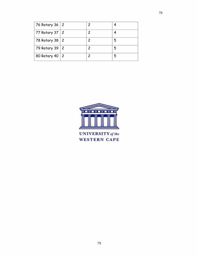
79
79
76 Rotary 36 2 2 4
77 Rotary 37 2 2 4
78 Rotary 38 2 2 5
79 Rotary 39 2 2 5
80 Rotary 40 2 2 5
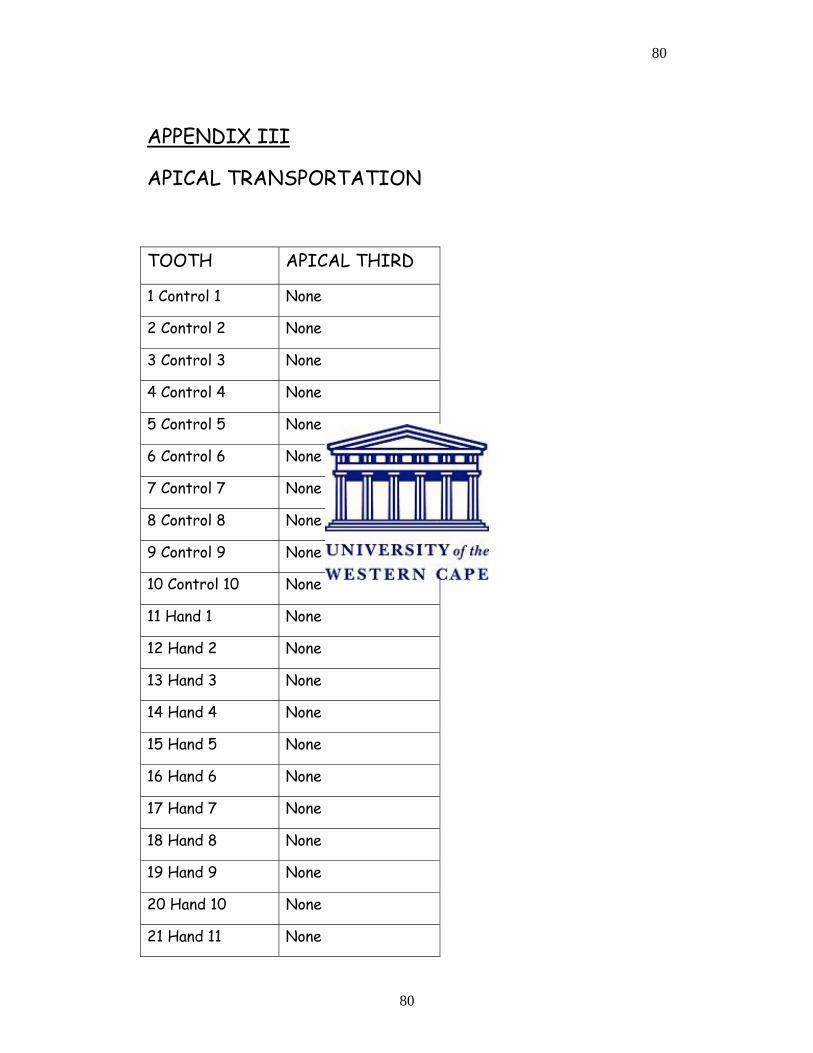
80
80
APPENDIX III
APICAL TRANSPORTATION
TOOTH APICAL THIRD
1 Control 1 None
2 Control 2 None
3 Control 3 None
4 Control 4 None
5 Control 5 None
6 Control 6 None
7 Control 7 None
8 Control 8 None
9 Control 9 None
10 Control 10 None
11 Hand 1 None
12 Hand 2 None
13 Hand 3 None
14 Hand 4 None
15 Hand 5 None
16 Hand 6 None
17 Hand 7 None
18 Hand 8 None
19 Hand 9 None
20 Hand 10 None
21 Hand 11 None

81
81
22 Hand 12 None
23 Hand 13 None
24 Hand 14 None
25 Hand 15 None
26 Hand 16 None
27 Hand 17 None
28 Hand 18 None
29 Hand 19 None
30 Hand 20 Present
31 Hand 21 None
32 Hand 22 Present
33 Hand 23 None
34 Hand 24 Present
35 Hand 25 None
36 Hand 26 None
37 Hand 27 None
38 Hand 28 None
39 Hand 29 Present
40 Hand 30 None
41 Hand 31 None
42 Hand 32 None
43 Hand 33 None
44 Hand 34 None
45 Hand 35 None
46 Hand 36 None
47 Hand 37 None
48 Hand 38 None

82
82
49 Hand 39 None
50 Hand 40 None
51 Rotary 1 None
52 Rotary 2 None
53 Rotary 3 None
54 Rotary 4 None
55 Rotary 5 None
56 Rotary 6 None
57 Rotary 7 None
58 Rotary 8 None
59 Rotary 9 None
60 Rotary 10 None
61 Rotary 11 None
62 Rotary 12 None
63 Rotary 13 None
64 Rotary 14 None
65 Rotary 15 None
66 Rotary 16 None
67 Rotary 17 None
68 Rotary 18 None
69 Rotary 19 None
70 Rotary 20 None
71 Rotary 21 None
72 Rotary 22 None
73 Rotary 23 None
74 Rotary 24 None
75 Rotary 25 None

83
83
76 Rotary 26 None
77 Rotary 27 None
78 Rotary 28 None
79 Rotary 29 None
80 Rotary 30 None
81 Rotary 31 None
82 Rotary 32 None
83 Rotary 33 None
84 Rotary 34 None
85 Rotary 35 None
86 Rotary 36 None
87 Rotary 37 None
88 Rotary 38 None
89 Rotary 39 None
90 Rotary 40 None
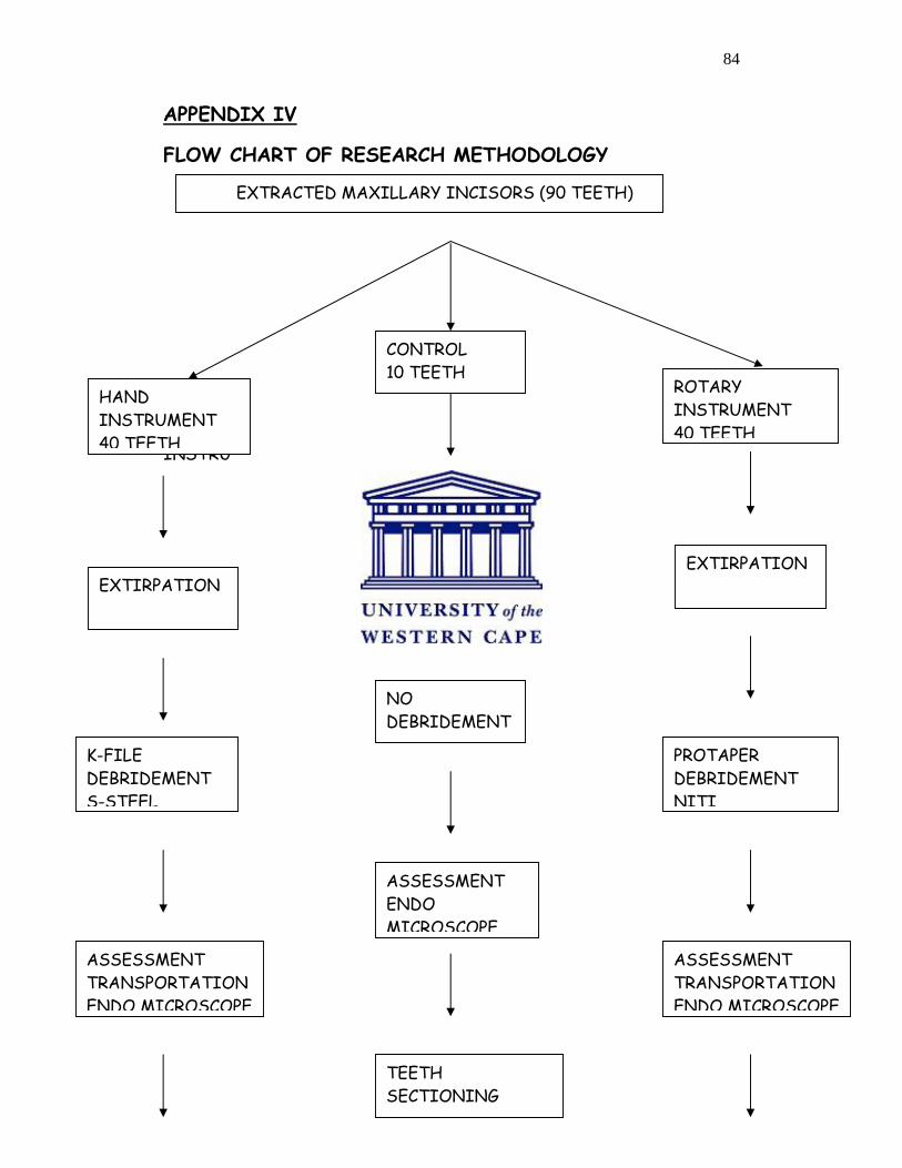
84
84
APPENDIX IV
FLOW CHART OF RESEARCH METHODOLOGY
HAND
INSTRU
CONTROL 10 TEETH
ROTARY INSTRUMENT 40 TEETH
EXTIRPATION EXTIRPATION
EXTIRPATION
K-FILE DEBRIDEMENT S-STEEL
NO DEBRIDEMENT
PROTAPER DEBRIDEMENT NITI
ASSESSMENT TRANSPORTATION ENDO MICROSCOPE
ASSESSMENT ENDO MICROSCOPE
ASSESSMENT TRANSPORTATION ENDO MICROSCOPE
TEETH SECTIONING
HAND INSTRUMENT 40 TEETH
EXTRACTED MAXILLARY INCISORS (90 TEETH)
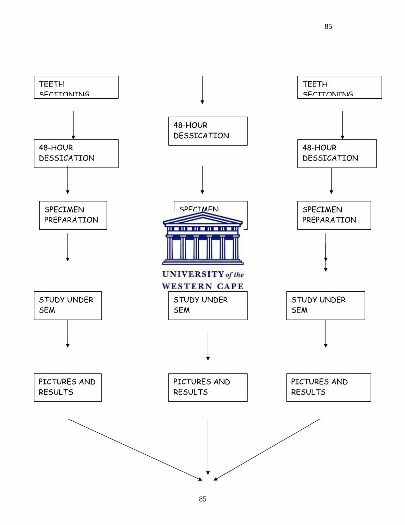
85
85
ST
TEETH SECTIONING
TEETH SECTIONING
48-HOUR DESSICATION
48-HOUR DESSICATION
48-HOUR DESSICATION
SPECIMEN PREPARATION
SPECIMEN PREPARATION
SPECIMEN PREPARATION
STUDY UNDER SEM
STUDY UNDER SEM
STUDY UNDER SEM
PICTURES AND RESULTS
PICTURES AND RESULTS
PICTURES AND RESULTS
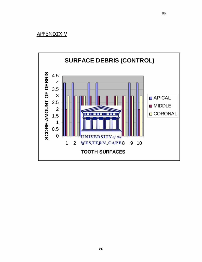
86
86
APPENDIX V
SURFACE DEBRIS (CONTROL)
00.5
11.5
22.5
33.5
44.5
1 2 3 4 5 6 7 8 9 10
TOOTH SURFACES
SCO
RE-A
MO
UNT
OF
DEBR
IS
APICALMIDDLECORONAL
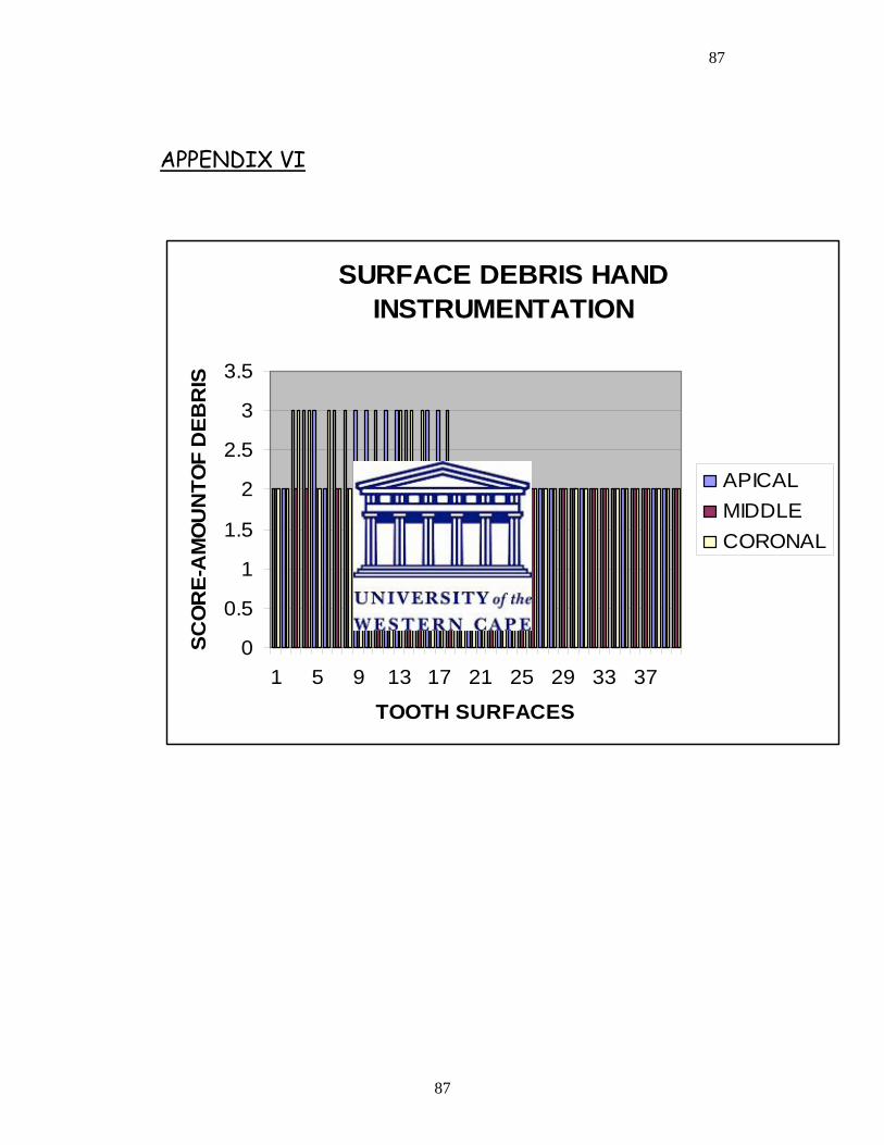
87
87
APPENDIX VI
SURFACE DEBRIS HAND INSTRUMENTATION
0
0.5
1
1.5
2
2.5
3
3.5
1 5 9 13 17 21 25 29 33 37
TOOTH SURFACES
SCO
RE-
AM
OU
NTO
F D
EBR
IS
APICALMIDDLECORONAL
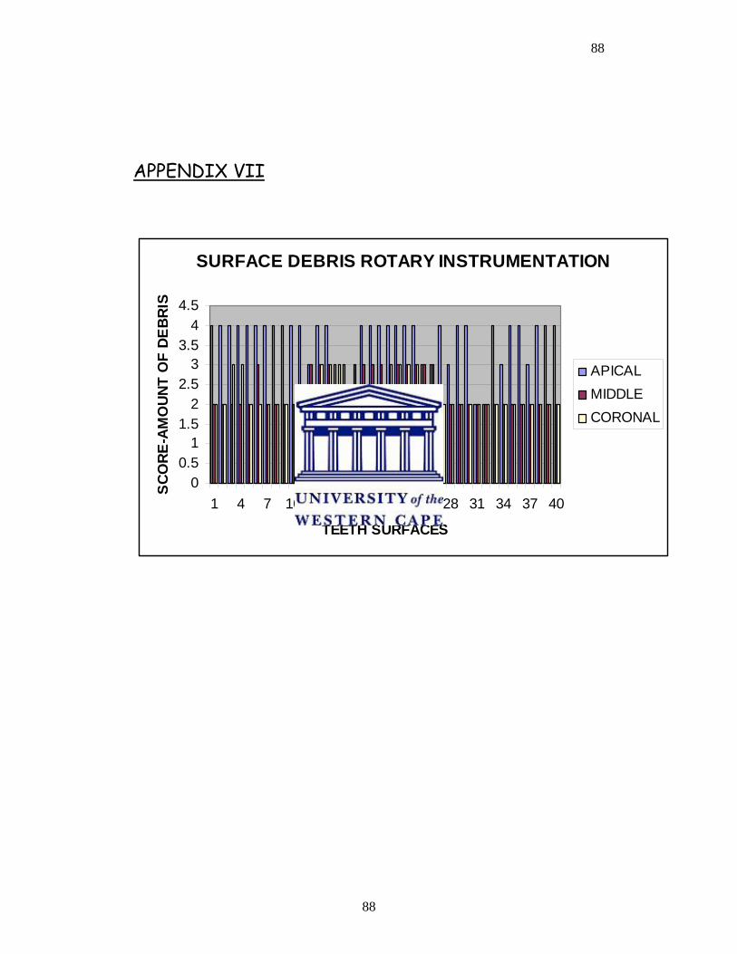
88
88
APPENDIX VII
SURFACE DEBRIS ROTARY INSTRUMENTATION
00.5
11.5
22.5
33.5
44.5
1 4 7 10 13 16 19 22 25 28 31 34 37 40
TEETH SURFACES
SCO
RE-A
MO
UNT
OF
DEBR
IS
APICALMIDDLECORONAL
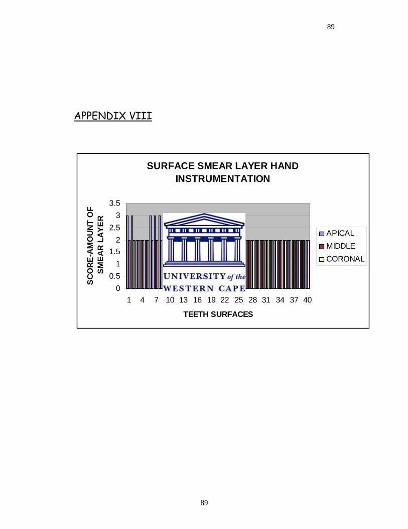
89
89
APPENDIX VIII
SURFACE SMEAR LAYER HAND INSTRUMENTATION
00.5
11.5
22.5
33.5
1 4 7 10 13 16 19 22 25 28 31 34 37 40
TEETH SURFACES
SCO
RE-A
MO
UNT
OF
SM
EAR
LAY
ER
APICALMIDDLECORONAL
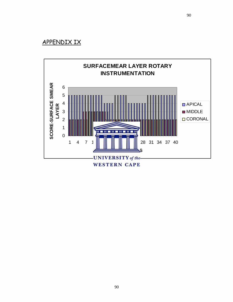
90
90
APPENDIX IX
SURFACEMEAR LAYER ROTARY INSTRUMENTATION
0
1
2
3
4
5
6
1 4 7 10 13 16 19 22 25 28 31 34 37 40
TEETH SURFACES
SCO
RE-S
URFA
CE S
MEA
RLA
YER APICAL
MIDDLECORONAL
91
91
REFERENCES:
1. AHLQUIST M, HENNINGSSON O, HULTENBY K, & OHLIN J
2001. The effectiveness of manual and rotary techniques in the
cleaning of root canals: a scanning electron microscopy study.
International Endodontic Journal, 34, 533-537.
2. ALAPATI SB, BRANTLEY WA, SVEC TA, POWERS JM, MITCHELL
JC 2003. Scanning electron microscope observations of new and
used nickel-titanium rotary files. Journal of Endodontics, 29, 667-
669.
3. AL-OMARI MA, DUMMER PM, NEWCOMBE RG, DOLLER R 1992.
Comparison of six files to prepare simulated root canals.
International Endodontic Journal, 25,67-81.
4. BARBIZAM VB, FARINIUK LF, MARCHESAN MA, PECORA MD,
SOUSA-NETO MD 2002. Effectiveness of manual and rotary for
cleaning flattened root canals. Journal of Endodontics, 28, 365-
366.
5. BEESON TJ, HARTWELL GR, THORNTON JD, GUNSOLLERY JC
2000. Comparison of apically extruded debris in straight canals:
conventional filing versus ProFile .04 taper series 29. Journal of
Endodontics, 24,18-22
6. BERUTTI E, ANGELINI E, RIGOLONE M, MIGLIARETTI G,
PASQUALINI D 2006. Influence of sodium hypochlorite on
92
92
fracture properties and corrosion of ProTaper rotary instruments.
International Endodontic Journal, 39, 693-699.
7. BRYANT ST, THOMPSON SA, AL-OMARI MOA, & DUMMER PMH
1998. The shaping ability of the profile rotary nickel-titanium with
ISO sized tips in simulated canals part 1. International Endodontic
Journal, 31, 275-281.
8. CALHOUN G, MONTGOMERY S 1988. The effects of four
instrumentation techniques on root canal shape. Journal of
Endodontics, 14, 273-277.
9. CIVJAN S, HUGET EF, DeSIMON LB 1975. Potential applications
of certain nickel titanium alloys. Journal of Dental Research, 54,
89-96.
10. COHEN S, BURNS RC 1998 Pathways of the pulp, 7th edition,
MOSBY, LONDON.
11. COHEN S, HARGREAVES KM 2006. The pathways to the pulp; 9th
Edition, ST LOUIS MOSBY ELSEVIER Pg 244-251
12. DAVIES SR, BRAYTON SM, GOLDMAN M 1972. The morphology
of the prepared root canal, utilizing injectable silicone. Journal of
Oral Surgery, 26,642-648.
13. Di FIORE PM, GENOV KI, KOMAROFF E, DASANAYAKE AP, LIN L
2006. Fracture of Profile nickel titanium rotary instruments: a
93
93
laboratory simulation assessment. International Endodontic
Journal, 39, 502-509.
14. DOBO-NAGY C, SERBAN T, SZABO J, NAGY G, MADLENA M
2002. A comparison of the shaping characteristics of two nickel-
titanium endodontic hand instruments. International Endodontic
Journal, 35, 283-288.
15. EGGERT C, PETERS O, BARBAKOW F 1999. Wear of nickel
titanium LightSpeed instruments evaluated by scanning electron
microscope. Journal of Endodontics, 25, 494-497.
16. ELMSALLATI EA, WADACHI R, EBRAHIM AK, SUDA H 2006.
Debris retention and wear in three different nickel titanium rotary
instruments. Australian Endodontic Journal, 32, 107-111.
17. ENDOWAVE, MORITA COMPANY, Osaka, Japan.
18. ESPOSITO PT, CUNNINGHAM CJ 1995. A comparison of canal
preparation with Nickel-titanium and stainless steel instruments.
Journal of Endodontics, 21,173-176.
19. FOSCHI F, NUCCI C, MONTEBUGNOLI L, MARCHIONNI S,
BRESCHI L, MALAGNINO VA, PRATI C 2004. SEM evaluation of
canal walls following the use of Mtwo and ProTaper NiTi rotary
instruments. International Endodontic Journal, 37,832-839.
94
94
20. GLOSSON CR 1995. A comparison of root canal preparations using
Nickel-titanium hand, Nickel-titanium engine driven and K-flex
endodontic instruments, Journal of Endodontics, 21, 146-151.
21. GROSSMAN LI, OLIET S, del RIO CE 1988. Preparation of root
canal, equipment and techniques for cleaning, shaping and irrigation.
International Endodontic Practice; 11th Edition, Philadelphia pages
179-227
22. GUELZOW A, STAMM O, MARTUS P, KIELBASSA AM 2005.
Comparative study of six rotary nickel-titanium systems and hand
instrumentation or root canal preparations. International
Endodontic Journal, 38, 743-752.
23. GULABIVALA. K, JARDINE SJ 1995. An in vitro Comparison of
canal preparation using two automated rotary NiTi instrumentation
techniques, International Endodontic Journal, 33, 381-391.
24. HATA M 1998 Comparison of shaping ability using Profile, GT file
and Flex-R endodontic instruments in simulated canals. Journal of
Endodontics, 28,316-321.
25. HERO 642, MICROMEGA, GENEVA
26. HULSMANN M, GRESSMANN G, SCHAFERS F 2003. A
comparative study of root canal preparation using FlexMaster and
HERO 642 rotary NiTi instruments. International Endodontic
Journal, 36, 358-366.
95
95
27. HULSMANN M, SCHADE M, SCHAFERS F 2001. A comparative
study of root canal preparation with HERO 642 and Quantec SC
rotary NiTi. International Endodontic Journal, 34, 538-546.
28. HULSMANN M, STRYGA F 1993. Comparison of root canal
preparations using different automated devices and hand
instrumentation. Journal of Endodontics, 19, 141-145
29. HULSMANN M, RUMMELIN C, SCHAFER F 1997. Root canal
cleanliness after preparation with different endodontic handpiece
and hand instruments: a comparative SEM investigation. Journal of
Endodontics, 5, 301-306.
30. IQBAL MK, MAGGIORE F, SUH B, EDWARDS KR, KANG J, KIM S
2003. Comparison of apical transportation in four NiTi rotary
instrumentation techniques. Journal of Endodontics, 29, 587-591.
31. JARDINE SJ, GULABIVALA K 2000(a). Shaping ability of Hero
642® rotary nickel-titanium instruments in simulated root canals:
Part one International Endodontic Journal, 33, 248-261.
32. JARDINE SJ. GULABIVALA K 2000 (b). Shaping ability of Hero
642® rotary nickel-titanium instruments in simulated root canals:
Part two. International Endodontic Journal, 33, 365-369.
33. JEON IS, LARZ S, SPANGBERG LSW, YOON TC, KAZEMI RB,
KUM KY 2003. Smear layer production by 3 rotary reamers with
different cutting blade designs in straight root canals: a scanning
96
96
electron microscopic study. Oral Surg Oral Med Oral Pathol Oral
Radiol Endod, 96, 601-607.
34. JODWAY.B, HULSMANN.M 2006. A comparative study of root
canal preparation with NiTi-TEE and K3 rotary Ni-Ti instrument.
International Endodontic Journal, 39, 71-80.
35. KEREKE K, TRONSTAD L 1977. Morphometric observations on the
root canals of human molars. Journal of Endodontics, 3, 114-118.
36. KUHN G and JORDAN L 2002. Fatigue and mechanical properties
of nickel-titanium endodontic instruments. Journal of Endodontics.
28 (10) 716-720.
37. K3, SYBRON ENDO
38. LI U-M, LEE B-S, SHIN C-T, LEN W-H, LIN C-P 2002. Cyclic
fatigue of endodontic nickel-titanium rotary instruments; Static
and dynamic tests. Journal of Endodontics 28 (6) 448-451.
39. LIGHTSPEED ,LIGHT SPEED TECHNOLOGY, SAN ANTONIO,
TEXAS
40. MAGGIORE F 1994. Endodontic preparation of curved canals using
Profile: evaluation of radiographic method and computerized
analysis. Journal of Endodontics, 29, 141-145.
97
97
41. McCOMB AND SMITH 1975. Preliminary scanning electron
microscopic study of root canals after endodontic procedure.
Journal of Endodontics, 1, 238-242.
42. MORGAN LF, MONTGOMERY S 1984. An evaluation of the crown
down pressureless technique. Journal of Endodontics,10, 491-498.
43. MTWO, VDW, MUNICH, GERMANY
44. OSCILLATING/RECIPROCATING FILES,
45. O’HOY PYZ, MESSER HH, PALAMARA EA 2003. The effect of
cleaning procedure and corrosion of NiTi files. International
Endodontic Journal, 36, 724-732.
46. PASHLEY EL, BIRDSONG NI, BOWMAN K, PASHLEY DH 1985.
Cytotoxic effects of NaOCl on vital tissues. Journal of
Endodontics, 2, 318-32
47. PROTAPER, DENTSPLY MAILLEFER.
48. QUANTEC, SYBRON ENDO
49. RACE, BRASSELER, SAVANNAH
50. SATTAPAN B, NERVO GJ, PALAMARA JE, MESSER HH 2000.
Defects in rotary nickel titanium files after clinical use. Journal of
Endodontics, 26, 161-165.
98
98
51. SCHAFER E, DZEPINA A, DANESH G 2003. Bending properties of
rotary nickel titanium instruments. Oral Surg Oral Med Oral Pathol
Oral Radiol Endod, 96, 757-763.
52. SCHAFER E, ERLE M, DAMMASCHKE T 2006(a). Comparative
study on the shaping ability and cleaning efficiency of rotary Mtwo
instruments (Part 1) International Endodontic Journal,39, 196-202.
53. SCHAFER E, ERLE M, DAMMASCHKE T 2006(b). Comparative
study on the shaping ability and cleaning efficiency of rotary Mtwo
instruments (Part 2) International Endodontic Journal, 39,203-
212.
54. SCHAFER E, FLOREK H 2003. Efficiency of rotary nickel titanium
K3 instruments compared with stainless steel hand K-flexofile
(Part1). Shaping ability in simulated curved canals. International
Endodontic Journal, 36, 199-207.
55. SCHAFER E, LOHMANN D 2002. Efficiency of rotary nickel-
titanium FlexMaster instruments compared with stainless steel
hand K-Flexofile (Part 2). Cleaning effectiveness and
instrumentation results in severely curved root canals of extracted
teeth. International Endodontic Journal, 35, 514-521.
56. SCHAFER E, VLASSIS M 2004. Comparative investigation of two
rotary nickel titanium instruments: ProTaper versus RaCe (Part
2).Cleaning effectiveness and shaping ability in severely curved
99
99
root canals of extracted teeth. International Endodontic Journal,
37,239-248.
57. SCHAFER E, ZAPKE K 2000. A comparative scanning electron
microscopic investigation of the efficacy of manual and automated
instrumentation of root canals. Journal of Endodontics, 26,660-
664.
58. SCHIRRMEISTER JF, STROHL C, ALTENBURGER MJ, WRBAS
KT, HELLWIG E 2006. Shaping ability and safety of five different
rotary nickel-titanium instruments compared with stainless steel
hand instrumentation in simulated curved root canal. Oral Surg
Oral Med Oral Path Oral Radiol Endod, 101,807-813.
59. SERAFINO C, GALLINA G, CUMBO E, and FERRARI M 2004.
Surface debris of canal walls after post space preparation in
endodontic treated teeth: A scanning electron microscopic study.
Oral Surg, Oral Med, Oral Path, 97,381-387.
60. SHEN Y, CHEUNG G.S-P, BIAN Z, PENG B 2006. Comparison of
defects in ProFile and Pro-Taper systems after clinical use. Journal
of Endodontics, 32 (1) 61-65.
61. SONNTAG D, DELSCHEN S, STACHNISS V 2003. Root canal
shaping with manual and rotary nickel titanium files performed by
students. International Endodontic Journal, 36, 715-723.
100
100
62. SUFFRIDGE CB, HARTWELL GR, WALKER TL 2003. Cleaning
efficiency of Nickel-Titanium GT and, 04 Rotary files when used in
a torque-controlled rotary handpiece. Journal of Endodontics, 29,
346-348.
63. SVEC TA, POWERS JM 2002. The deterioration of Rotary Nickel-
Titanium files under controlled conditions. Journal of Endodontics,
28, 105-107.
64. TAN BT, MESSER HH 2002. The Quality of Apical Canal
Preparation Using Hand and Rotary Instruments with Specific
Criteria for Enlargement Based on Initial Apical File Size. Journal
Of Endodontics, 26, 658-664.
65. THOMPSON SA, DUMMER PMH 1997. Shaping ability of Profile,
04 taper series 29 rotary nickel-titanium instruments in simulated
canals. Part 1. International Endodontic Journal, 30, 1-7.
66. THOMPSON SA, DUMMER PMH 2000(a). Shaping ability of Hero
642 rotary nickel-titanium instruments in simulated root canals
(Part 1) International Endodontic Journal, 33, 248-254.
67. THOMPSON SA, DUMMER PMH 2000(b). Shaping ability of Hero
642 rotary nickel-titanium instruments in simulated root canals
(Part 2) International Endodontic Journal, 33, 255-261.
68. TORABINEJAD M, HANDYSIDES R, KHADEMI AA, BAKLAND LF
2002. Clinical implications of the smear layer in endodontics: A
101
101
Review, Oral Surg Oral Med Oral Path Oral Radio Endod, 94, 658-
666.
69. VERSUMER J, HULSMANN M, SCHAFER F 2002. A comparative
study of root canal preparations using Profile, 04 and LightSpeed
rotary nickel titanium instruments.
70. WALIA H, BANTLEY WA, GERSTEIN 1988. An initial Investigation
of the bending and torsional properties of Nickel-titanium root
canal files. Journal of Endodontics, 14, 346-351.
71. WALTON RE 1976. Histological evaluation of different methods of
enlarging the pulp canal space. Journal of Endodontics, 2, 304-311.
72. YAO JH, SCHWARTZ SC, BEESON TJ 2006. Cyclic fatigue of
three types of rotary nickel titanium files in a dynamic model.
Journal Of Endodontics, 32,55-57.