Embed Size (px)
Citation preview
March 18-20, 2013 – Orlando, Florida (USA)
THE EFFECTS OF THE PLANFORM SHAPE ON DRAG
POLAR CURVES OF WINGS:
FLUID-STRUCTURE INTERACTION ANALYSES
RESULTS
Aerospace Engineering
University of Pisa (Italy)
Speaker: Aerospace Engineer Matteo CIABATTARI [email protected]
Authors: M.R. Chiarelli, M. Ciabattari, M. Cagnoni, G. Lombardi
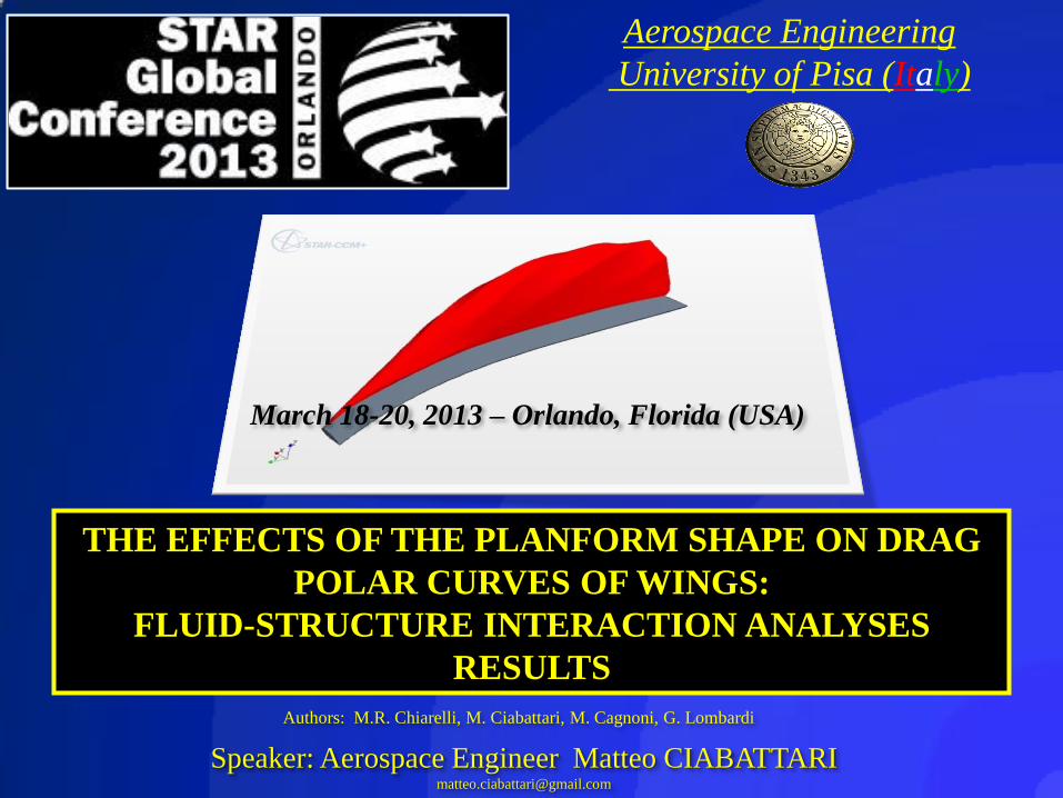
Relationship between Critical Conditions
and the component “U∞∙ cosΛ”
STAR Global Conference March 18-20, 2013
Orlando, Florida (USA)
Aerospace Engineering
University of Pisa (Italy)
STAR Global Conference March 18-20, 2013
Orlando, Florida (USA)
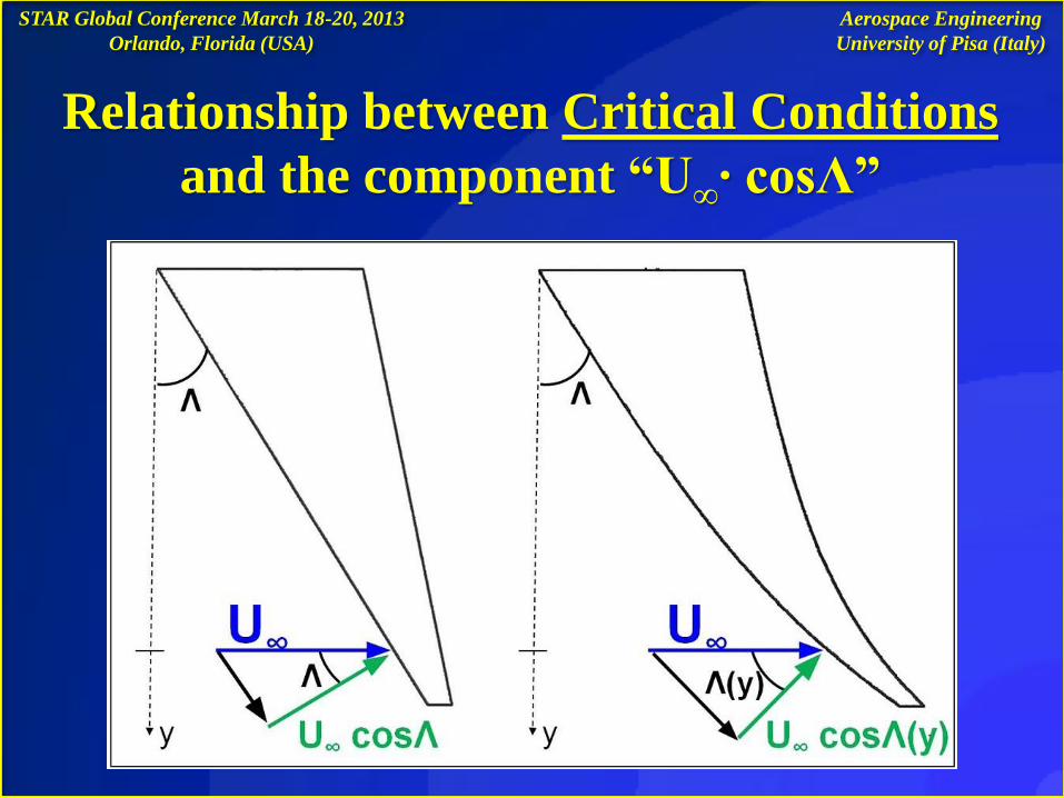
AEROELASTIC ANALYSES OF TWO HALF – WING MODELS:
CURVED AND SWEPT PLAN - FORM
The curved plan-form causes a variable angle of sweep along the wing span, so, in
the transonic flight conditions wave drag effects are strongly reduced
The effects of the plan-form shape on drag polar curves (fixed values of CL) leads to
the reduction of CD of 7% - 10%
The curved plan-form configuration improves the wing’s aeroelastic behavior :
Analyses have been carried out by using STAR - CCM+® 6.04.14 and Abaqus® 6.11
in “co - simulation”
The reaction moments and stress values at the root of the curved wing are reduced by
about 5% - 8 %
Abstract
Aerospace Engineering
University of Pisa (Italy)
Index
1. Introduction
2. Rigid wing’ s model : STAR - CCM+® 6.04.14 CFD analyses
3. Elastic wing’ s model : Fluid - structure - interaction (FSI) analyses
STAR - CCM+® 6.04.14 and Abaqus® 6.11 “co - simulation”
4. Detailed analysis of rigid and elastic models results
5. Conclusions and future research activity
STAR Global Conference March 18-20, 2013
Orlando, Florida (USA)
Aerospace Engineering
University of Pisa (Italy)
STAR Global Conference March 18-20, 2013
Orlando, Florida (USA)
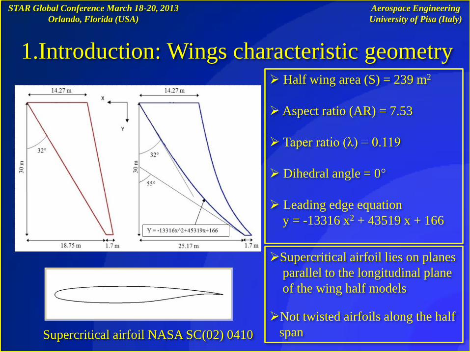
1.Introduction: Wings characteristic geometry Half wing area (S) = 239 m2
Aspect ratio (AR) = 7.53
Taper ratio (λ) = 0.119
Dihedral angle = 0°
Leading edge equation
y = -13316 x2 + 43519 x + 166
Supercritical airfoil NASA SC(02) 0410
Supercritical airfoil lies on planes
parallel to the longitudinal plane
of the wing half models
Not twisted airfoils along the half
span
Aerospace Engineering
University of Pisa (Italy)
STAR Global Conference March 18-20, 2013
Orlando, Florida (USA)
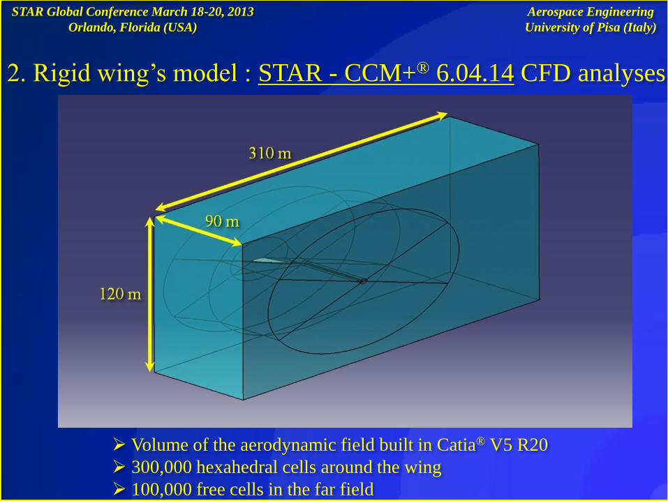
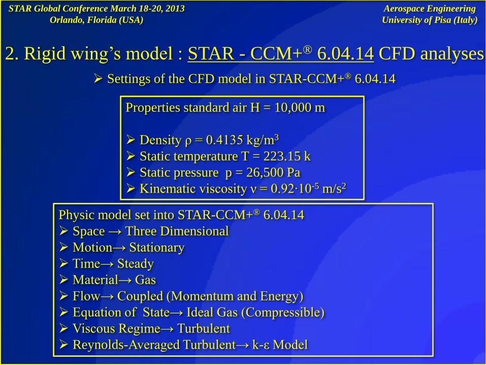
2. Rigid wing’s model : STAR - CCM+® 6.04.14 CFD analyses
Volume of the aerodynamic field built in Catia® V5 R20
300,000 hexahedral cells around the wing
100,000 free cells in the far field
Aerospace Engineering
University of Pisa (Italy)
STAR Global Conference March 18-20, 2013
Orlando, Florida (USA)
2. Rigid wing’s model : STAR - CCM+® 6.04.14 CFD analyses
Settings of the CFD model in STAR-CCM+® 6.04.14
Properties standard air H = 10,000 m
Density ρ = 0.4135 kg/m3
Static temperature T = 223.15 k
Static pressure p = 26,500 Pa
Kinematic viscosity ν = 0.92∙10-5 m/s2
Physic model set into STAR-CCM+® 6.04.14
Space → Three Dimensional
Motion→ Stationary
Time→ Steady
Material→ Gas
Flow→ Coupled (Momentum and Energy)
Equation of State→ Ideal Gas (Compressible)
Viscous Regime→ Turbulent
Reynolds-Averaged Turbulent→ k-ε Model
Aerospace Engineering
University of Pisa (Italy)
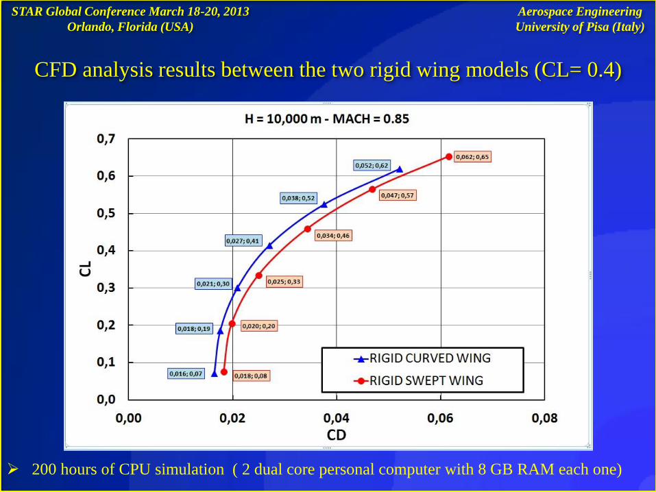
CFD analysis results between the two rigid wing models (CL= 0.4)
STAR Global Conference March 18-20, 2013
Orlando, Florida (USA)
200 hours of CPU simulation ( 2 dual core personal computer with 8 GB RAM each one)
Aerospace Engineering
University of Pisa (Italy)
STAR Global Conference March 18-20, 2013
Orlando, Florida (USA)
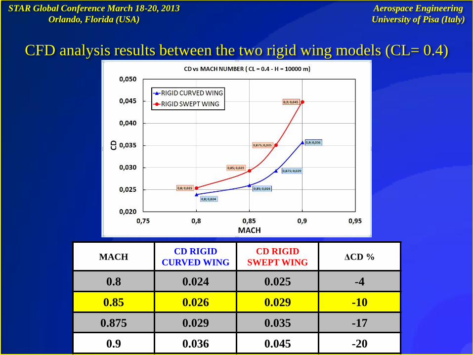
CFD analysis results between the two rigid wing models (CL= 0.4)
MACH CD RIGID
CURVED WING
CD RIGID
SWEPT WING ΔCD %
0.8 0.024 0.025 -4
0.85 0.026 0.029 -10
0.875 0.029 0.035 -17
0.9 0.036 0.045 -20
Aerospace Engineering
University of Pisa (Italy)
The CFD model and the FEM structural model must be perfectly complementary
in the areas where take place the exchange of the nodal forces and the
displacement nodal values: in Catia® V5 R20 an aerodynamic field that surround
the wing is constructed (slide n. 6)
STAR Global Conference March 18-20, 2013
Orlando, Florida (USA)
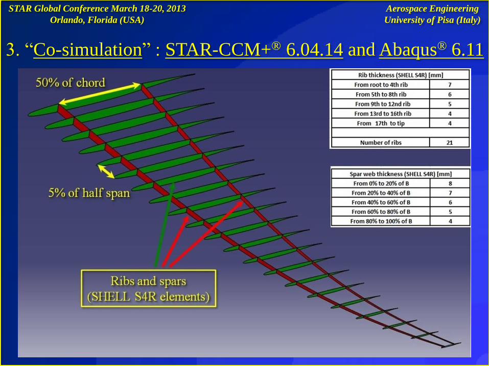
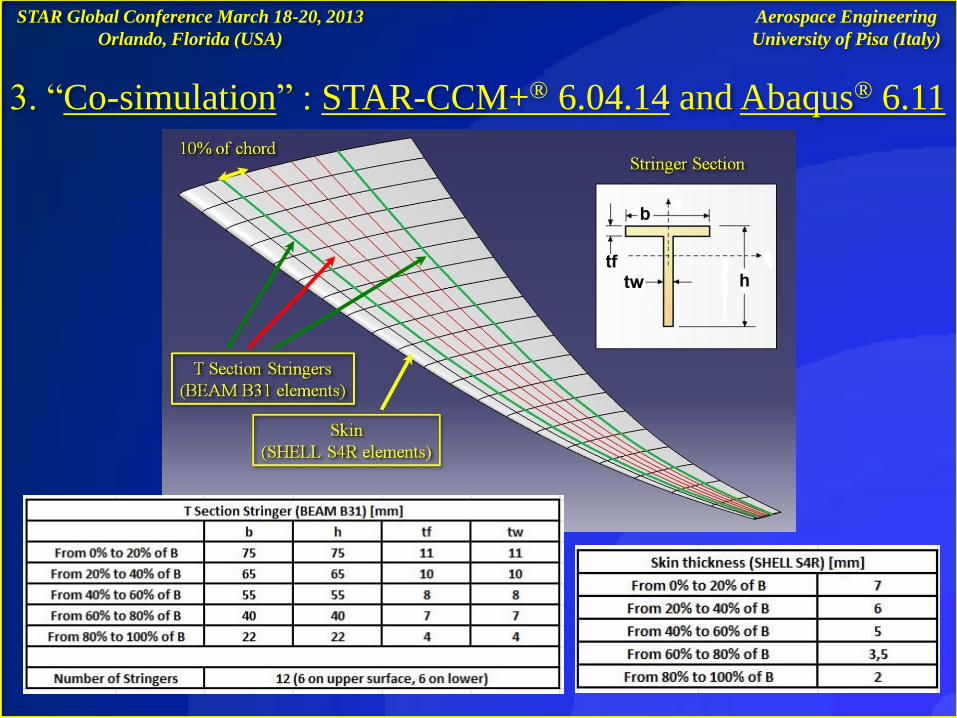
3. “Co-simulation” : STAR-CCM+® 6.04.14 and Abaqus ® 6.11
Structural model of swept and curved wing has been built by using Catia ® V5 R20
Structural properties and dimensions have been assigned to the components
(SKIN, STRINGERS, RIBS, SPARS) in Abaqus® 6.11
Both models have the same dimensions for all their characteristic components
The results (static Aeroelastic analyses) do not take into account the distributions
of the structural or not structural weight: little influence on the deformation
shape of the wing at the examined flight conditions
Aerospace Engineering
University of Pisa (Italy)
STAR Global Conference March 18-20, 2013
Orlando, Florida (USA)
3. “Co-simulation” : STAR-CCM+® 6.04.14 and Abaqus® 6.11
Aerospace Engineering
University of Pisa (Italy)
3. “Co-simulation” : STAR-CCM+® 6.04.14 and Abaqus® 6.11
STAR Global Conference March 18-20, 2013
Orlando, Florida (USA)
Aerospace Engineering
University of Pisa (Italy)
STAR Global Conference March 18-20, 2013
Orlando, Florida (USA)
3. “Co-simulation” : STAR-CCM+® 6.04.14 and Abaqus® 6.11
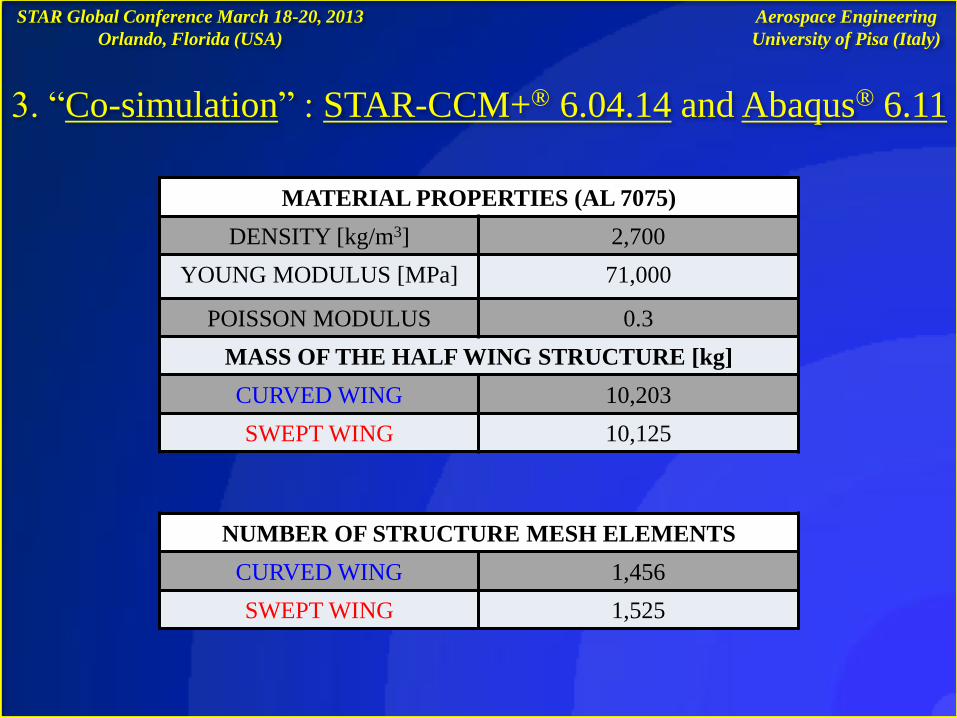
NUMBER OF STRUCTURE MESH ELEMENTS
CURVED WING 1,456
SWEPT WING 1,525
MATERIAL PROPERTIES (AL 7075)
DENSITY [kg/m3] 2,700
YOUNG MODULUS [MPa] 71,000
POISSON MODULUS 0.3
MASS OF THE HALF WING STRUCTURE [kg]
CURVED WING 10,203
SWEPT WING 10,125
Aerospace Engineering
University of Pisa (Italy)
STAR Global Conference March 18-20, 2013
Orlando, Florida (USA)
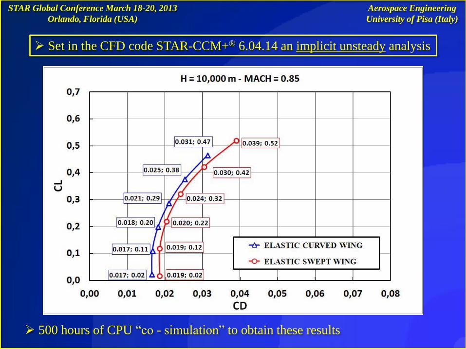
500 hours of CPU “co - simulation” to obtain these results
Set in the CFD code STAR-CCM+® 6.04.14 an implicit unsteady analysis
Aerospace Engineering
University of Pisa (Italy)
STAR Global Conference March 18-20, 2013
Orlando, Florida (USA)
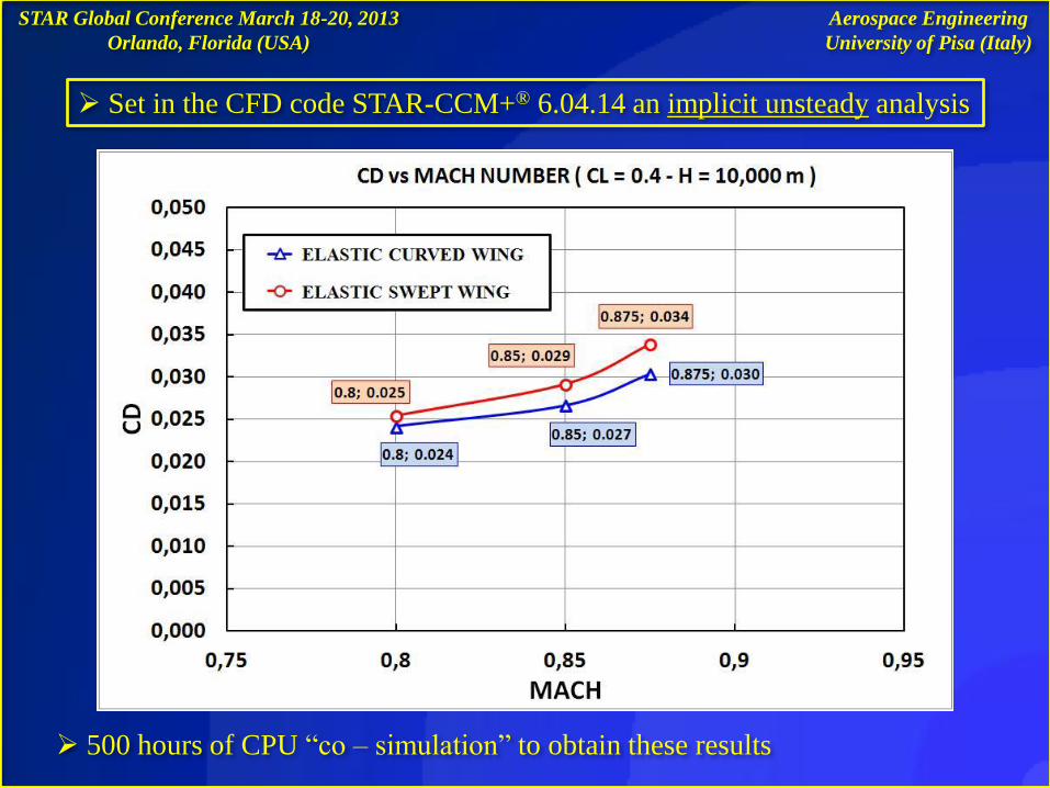
500 hours of CPU “co – simulation” to obtain these results
Aerospace Engineering
University of Pisa (Italy)
Set in the CFD code STAR-CCM+® 6.04.14 an implicit unsteady analysis
STAR Global Conference March 18-20, 2013
Orlando, Florida (USA)
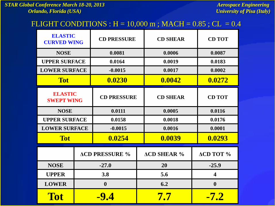
ELASTIC
CURVED WING CD PRESSURE CD SHEAR CD TOT
NOSE 0.0081 0.0006 0.0087
UPPER SURFACE 0.0164 0.0019 0.0183
LOWER SURFACE -0.0015 0.0017 0.0002
Tot 0.0230 0.0042 0.0272
ELASTIC
SWEPT WING CD PRESSURE CD SHEAR CD TOT
NOSE 0.0111 0.0005 0.0116
UPPER SURFACE 0.0158 0.0018 0.0176
LOWER SURFACE -0.0015 0.0016 0.0001
Tot 0.0254 0.0039 0.0293
ΔCD PRESSURE % ΔCD SHEAR % ΔCD TOT %
NOSE -27.0 20 -25.9
UPPER 3.8 5.6 4
LOWER 0 6.2 0
Tot -9.4 7.7 -7.2
FLIGHT CONDITIONS : H = 10,000 m ; MACH = 0.85 ; CL = 0.4
Aerospace Engineering
University of Pisa (Italy)
STAR Global Conference March 18-20, 2013
Orlando, Florida (USA)
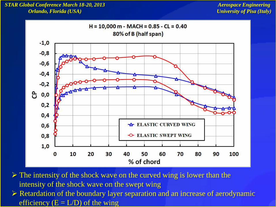
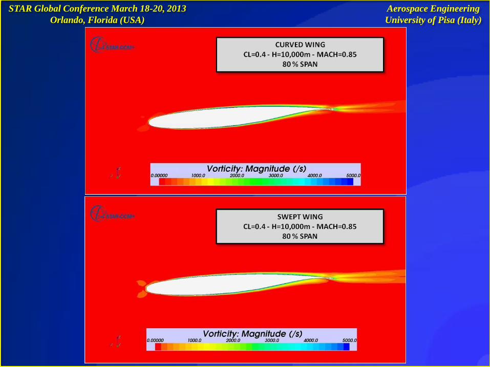
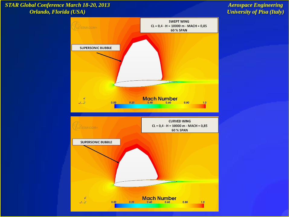
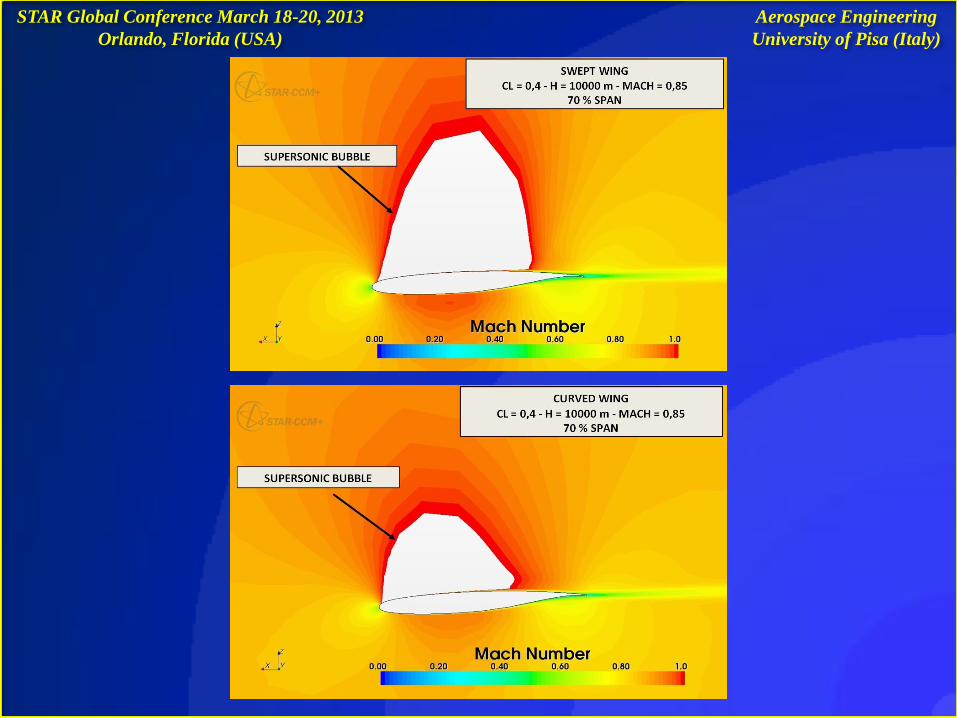
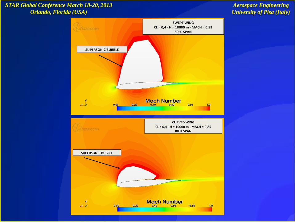
The intensity of the shock wave on the curved wing is lower than the
intensity of the shock wave on the swept wing
Retardation of the boundary layer separation and an increase of aerodynamic
efficiency (E = L/D) of the wing
Aerospace Engineering
University of Pisa (Italy)
STAR Global Conference March 18-20, 2013
Orlando, Florida (USA)
Aerospace Engineering
University of Pisa (Italy)
STAR Global Conference March 18-20, 2013
Orlando, Florida (USA)
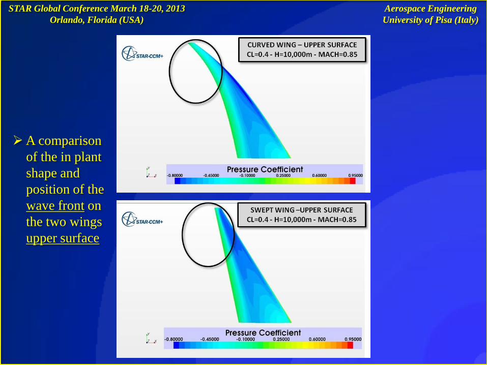
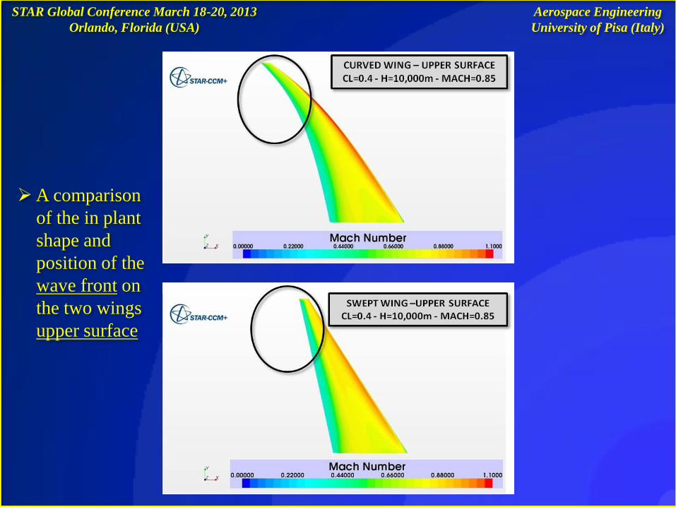
A comparison
of the in plant
shape and
position of the
wave front on
the two wings
upper surface
Aerospace Engineering
University of Pisa (Italy)
STAR Global Conference March 18-20, 2013
Orlando, Florida (USA)
A comparison
of the in plant
shape and
position of the
wave front on
the two wings
upper surface
Aerospace Engineering
University of Pisa (Italy)
STAR Global Conference March 18-20, 2013
Orlando, Florida (USA)
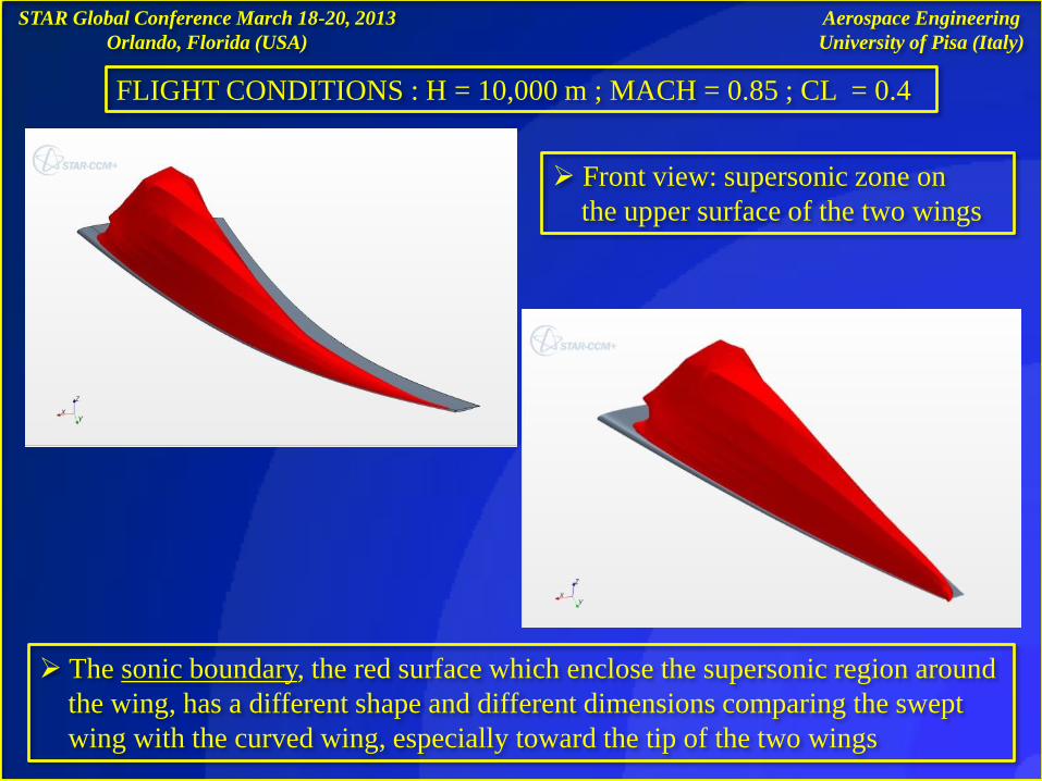
The sonic boundary, the red surface which enclose the supersonic region around
the wing, has a different shape and different dimensions comparing the swept
wing with the curved wing, especially toward the tip of the two wings
FLIGHT CONDITIONS : H = 10,000 m ; MACH = 0.85 ; CL = 0.4
Front view: supersonic zone on
the upper surface of the two wings
Aerospace Engineering
University of Pisa (Italy)
STAR Global Conference March 18-20, 2013
Orlando, Florida (USA)
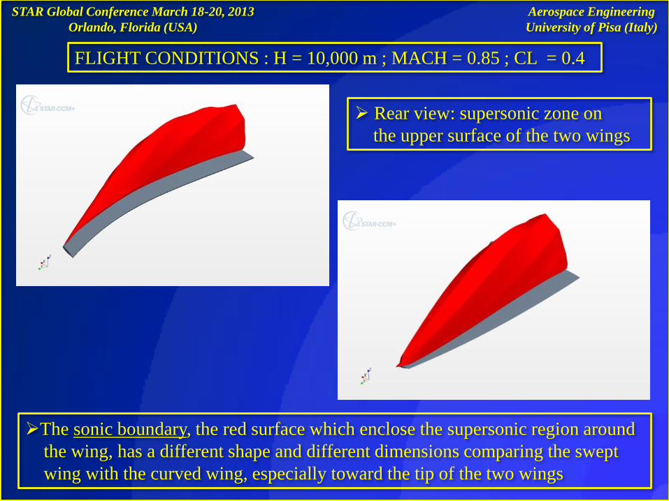
Rear view: supersonic zone on
the upper surface of the two wings
The sonic boundary, the red surface which enclose the supersonic region around
the wing, has a different shape and different dimensions comparing the swept
wing with the curved wing, especially toward the tip of the two wings
Aerospace Engineering
University of Pisa (Italy)
FLIGHT CONDITIONS : H = 10,000 m ; MACH = 0.85 ; CL = 0.4
STAR Global Conference March 18-20, 2013
Orlando, Florida (USA)
Aerospace Engineering
University of Pisa (Italy)
STAR Global Conference March 18-20, 2013
Orlando, Florida (USA)
Aerospace Engineering
University of Pisa (Italy)
STAR Global Conference March 18-20, 2013
Orlando, Florida (USA)
Aerospace Engineering
University of Pisa (Italy)
STAR Global Conference March 18-20, 2013
Orlando, Florida (USA)
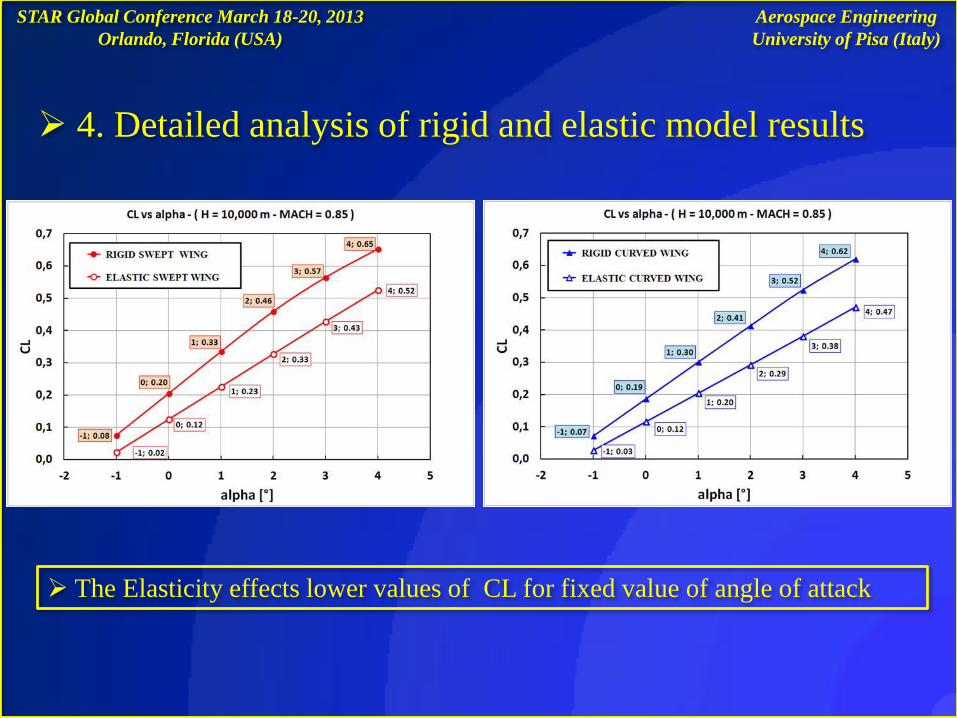
4. Detailed analysis of rigid and elastic model results
The Elasticity effects lower values of CL for fixed value of angle of attack
Aerospace Engineering
University of Pisa (Italy)
STAR Global Conference March 18-20, 2013
Orlando, Florida (USA)
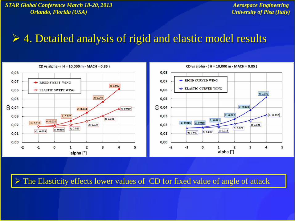
4. Detailed analysis of rigid and elastic model results
The Elasticity effects lower values of CD for fixed value of angle of attack
Aerospace Engineering
University of Pisa (Italy)
STAR Global Conference March 18-20, 2013
Orlando, Florida (USA)
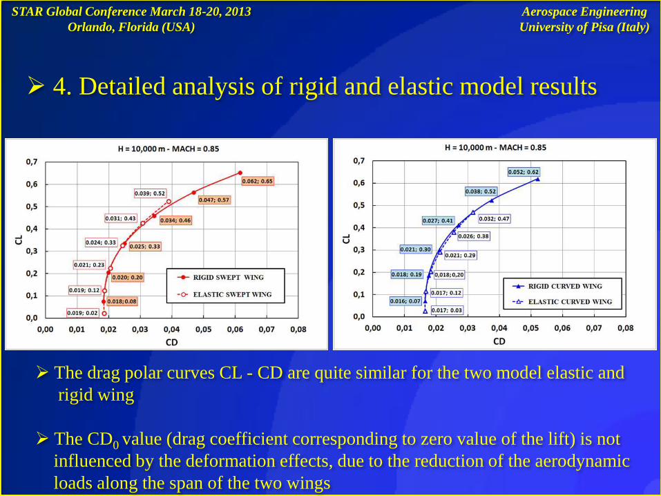
4. Detailed analysis of rigid and elastic model results
The drag polar curves CL - CD are quite similar for the two model elastic and
rigid wing
The CD0 value (drag coefficient corresponding to zero value of the lift) is not
influenced by the deformation effects, due to the reduction of the aerodynamic
loads along the span of the two wings
Aerospace Engineering
University of Pisa (Italy)
STAR Global Conference March 18-20, 2013
Orlando, Florida (USA)
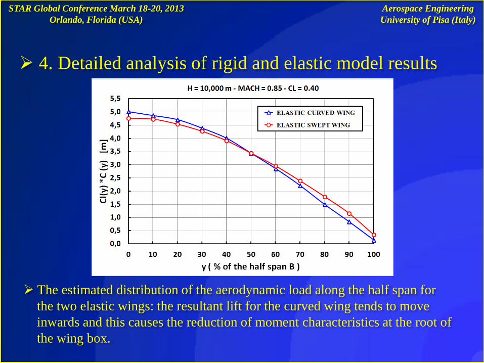
4. Detailed analysis of rigid and elastic model results
The estimated distribution of the aerodynamic load along the half span for
the two elastic wings: the resultant lift for the curved wing tends to move
inwards and this causes the reduction of moment characteristics at the root of
the wing box.
Aerospace Engineering
University of Pisa (Italy)
STAR Global Conference March 18-20, 2013
Orlando, Florida (USA)
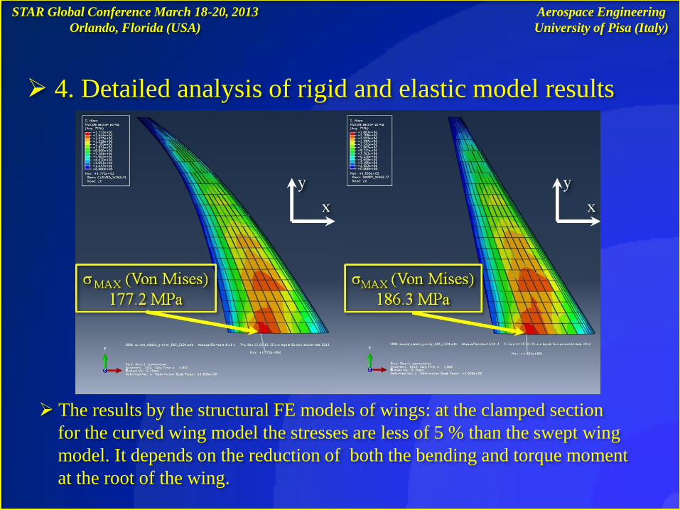
4. Detailed analysis of rigid and elastic model results
The results by the structural FE models of wings: at the clamped section
for the curved wing model the stresses are less of 5 % than the swept wing
model. It depends on the reduction of both the bending and torque moment
at the root of the wing.
Aerospace Engineering
University of Pisa (Italy)
STAR Global Conference March 18-20, 2013
Orlando, Florida (USA)
5. Conclusion
Also taking into account the elasticity effect of the wing - box structure the
curved plan-form of a wing favorable influences both CP and MACH
distribution along the wing span
The results discussed in the present paper agree with previous results published
by the authors and confirm that the feasibility of the examined novel wing
configuration can be reach adopting standard design technology
Flight conditions: H = 10000 m ; CL =0.4 ; MACH = 0.85
The curved wing shows a reduction of CD of 7% than the swept wing
The structural bending moment and torsion moment of curved elastic model are
less of 5% : the stresses in the skin of the curved wing are less of 5%
Aerospace Engineering
University of Pisa (Italy)
STAR Global Conference March 18-20, 2013
Orlando, Florida (USA)
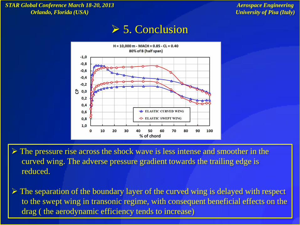
The pressure rise across the shock wave is less intense and smoother in the
curved wing. The adverse pressure gradient towards the trailing edge is
reduced.
The separation of the boundary layer of the curved wing is delayed with respect
to the swept wing in transonic regime, with consequent beneficial effects on the
drag ( the aerodynamic efficiency tends to increase)
Aerospace Engineering
University of Pisa (Italy)
5. Conclusion
STAR Global Conference March 18-20, 2013
Orlando, Florida (USA)
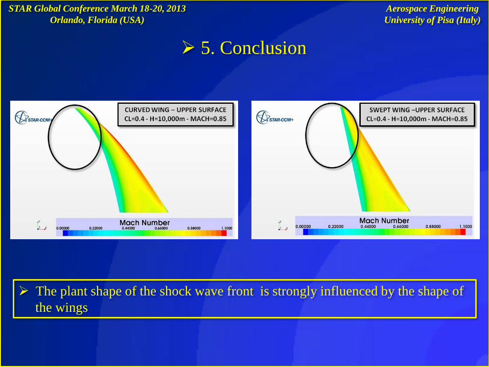
The plant shape of the shock wave front is strongly influenced by the shape of
the wings
Aerospace Engineering
University of Pisa (Italy)
5. Conclusion
STAR Global Conference March 18-20, 2013
Orlando, Florida (USA)
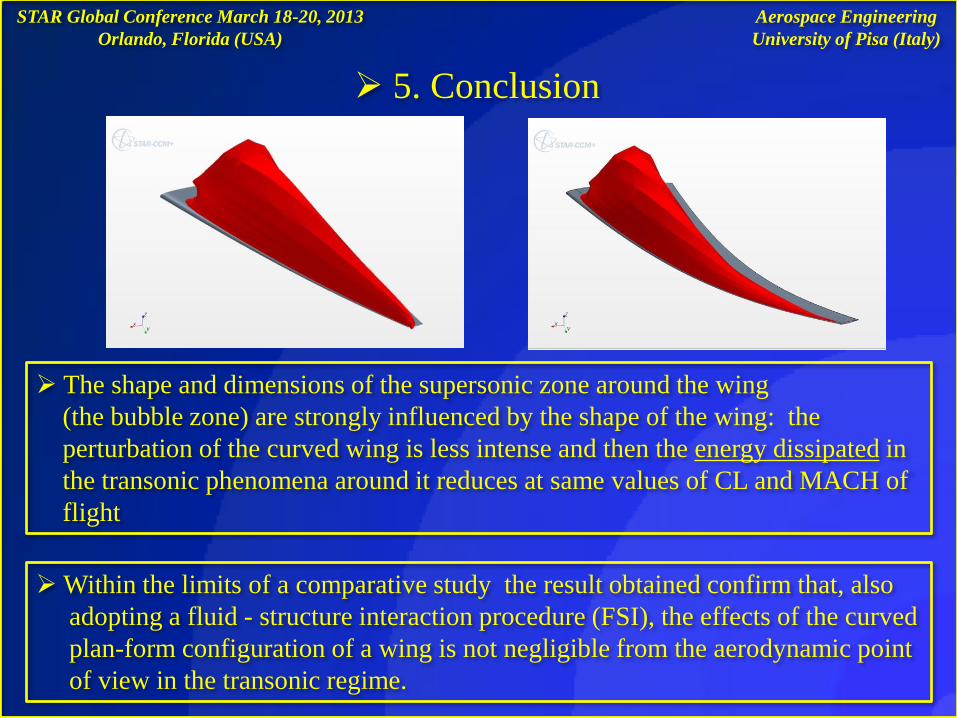
The shape and dimensions of the supersonic zone around the wing
(the bubble zone) are strongly influenced by the shape of the wing: the
perturbation of the curved wing is less intense and then the energy dissipated in
the transonic phenomena around it reduces at same values of CL and MACH of
flight
Within the limits of a comparative study the result obtained confirm that, also
adopting a fluid - structure interaction procedure (FSI), the effects of the curved
plan-form configuration of a wing is not negligible from the aerodynamic point
of view in the transonic regime.
Aerospace Engineering
University of Pisa (Italy)
5. Conclusion
Dynamic response analyses ( Flutter Behavior) by using FSI analysis procedure :
“Co - simulation” by using STAR-CCM+® 6.04.14 and Abaqus® 6.11
STAR Global Conference March 18-20, 2013
Orlando, Florida (USA)
Future research activity
Thanks to the “Co-simulation” by using STAR-CCM+® 6.04.14 and Abaqus® 6.11
It has been possible to examine with a good level of reliability a complex
Aeroelastic phenomena with minimum computational resources :
Only two Personal Computer with 8 GB of Ram each one
Aerospace Engineering
University of Pisa (Italy)

THE END (For the moment...)
Thank you
STAR Global Conference March 18-20, 2013
Orlando, Florida (USA)
Prof. Eng. Mario Rosario CHIARELLI
(Aerospace Engineering - University of Pisa, Italy)
phone number:+390502217253
e-mail: [email protected]
Speaker: Aerospace Eng. Matteo CIABATTARI
phone number :+393284771319
e-mail: [email protected] or [email protected]
Aerospace Engineering
University of Pisa (Italy)