Embed Size (px)
Citation preview
63rd
Annual Assembly & International Conference of the International Institute of Welding
11-17 July 2010, Istanbul, Turkey
AWST-10/85
847
The Effect of Shielding Gases on the Microstructure and Thoughness
of Stainless Steels Weldments by FCAW
R. Yılmaz 1,a
, M. Tümer 2,b
1Sakarya University, Faculty of Technical Education, Metal Teaching 54187, Sakarya, Turkey
2 Gedik Eğitim Vakfı 34913 Şeyhli, Pendik, İstanbul, Turkey
Abstract
In this study AISI 316 types of austenitic stainless steels
were welded by FCAW (flux cored arc welding) using
ER 316L flux cored filler metal under various shielding
gas compositions such as Ar + 12% CO2, Ar + 20%
CO2, Ar + 50% CO2 and 100% CO2 gases. The aim of
the current study is that effects of shielding gas
compositions on the microstructure and toughness of
AISI 316L austenitic stainless steels weldments were
investigated. Charpy V notch impact tests were carried
out at 0oC temperature. The results were indicated that
the shielding gas compositions have an influence on
toughness values. The study showed that variation of
those values depended on δ-ferrite content in the weld
metal. δ-ferrite content decrease with increasing CO2
percentages in the shielding gas. Decreasing δ-ferrite
rate in the weld metal have negative effects on the
toughness values of the weldments.
Keywords: Austenitic stainless steel, AISI 316, impact
toughness, FCAW, microstructure, shielding gas,
1. Introduction
The austenitic stainless steels (Fe-Cr-Ni) have excellent
mechanical properties and corrosion resistance [1-3].
Due to having combine properties, their usage in various
applications such as storage tanks, pipe, and pressures
vessel valves, pumps, distiller etc have been increasing.
Better strength, toughness and formability are required
for this kind of applications mentioned above [4]. 300
serious austenitic stainless steels are most popular steels
and their most important and conspicuous properties are
their excellent toughness and corrosion resistance [1-4].
Due to austenitic stainless steels having fcc structure,
they have higher toughness values. A higher notch
toughness values and it is almost independent from
temperature, thus brittle structure does not occur like low
carbon steels having bcc structure, and is strongly
temperature dependent. Austenitic stainless steels
maintain their higher notch toughness even at cryogenic
temperature (5-8). The mechanical properties of
austenitic stainless steels provide an excellent
combination of better strength, ductility and toughness
over a broad temperature range compare with notch
impact toughness of low carbon steels (4-6).
AISI 316L grades austenitic stainless steels also retain
their strength advantage over the AISI 304 grades at
elevated temperatures. AISI 316L austenitic stainless
steels contain molybdenum and make it resistant to a
wide range of corrosive environments. Most of the
austenitic stainless steels grades lie in the 300 serious.
Some alloying elements modified grades to provide
special properties required for certain industrial
applications. AISI 316L grades austenitic stainless steels
contain 2-3% molybdenum, which is added to increases
corrosion resistance and allow usage of this materials at
high temperatures (1, 2).
The gas-shielded arc welding methods are generally
classified in to two methods such as solid wires and flux-
cored wires (FCAW). Usage of FCAW is increasing year
by year because of its workability and efficiency. FCAW
method is suitable for mechanization and robotization
and easy for applying, thus provide efficiency and speedy
during welding process of the sheets having high
thickness (6, 9-12).
FCAW method have received great attention from
welders and contractors recently compare to
conventional GMAW because flux cored wire have a lot
of advantages such as outstanding productivity, deep
penetration, spatter reduced welding behavior, higher
deposition rates and high welding speed (11, 12). In the
welding process, a shielding gas is used to protect molten
metal from negative affection of atmospheric nitrogen
and oxygen as the weld pool is being formed. The
shielding gas also provides a stable arc and uniform
metal transfer during welding process. In addition to that
the quality, deposition rates, productivity, surface
appearance and efficiency of the welding are strongly
dependant to shielding gas used (13-16). Microstructure
and mechanical properties have been influenced by
composition of shielding gases used during welding
848
process. CO2 is most frequently used in the FCAW
process as the shielding gas (6). CO2 and argon in
various mixtures is also used. The selection of the
shielding gas is crucial for obtaining optimal properties
of the weldment. Therefore, number investigations have
been performed regarding the affection of the shielding
gas composition on mechanical properties of austenitic
stainless steel weldments (5, 6, 13-16). Nevertheless, just
a few studies about gas composition on microstructure
and mechanical properties of weldment by FCAW are
available in the literature.
Determination of mechanical properties such as hardness
variation, impact toughness and tensile strength and
fatigue etc. of the construction made from austenitic
stainless steel weldments is crucial for safety using.
Those constructions can be exposed dynamic load during
working in various applications, therefore, impact
toughness behavior become more important under
different working condition such as temperature and
environment.
The present study investigates the influence of shielding
gas composition on the notch impact toughness of AISI
316L austenitic stainless steels. Four different gas
compositions were used. Optical and scanning electron
microscopy studies and hardness measurement were also
carried out.
2. Experimental Procedure
AISI 316L grades austenitic stainless steels were used in
this study. E316LT1-1/4 flux cored wire with diameter of
1.2 mm was used grades austenitic stainless steels as a
filler material. The chemical composition of base
materials and filler materials were given in Table 1.
Those AISI 316L grades austenitic stainless steels plates
were prepared for joining of FCAW with dimension of
400 (l) x150 (w)x 10 (t) mm3. V shaped grove were used
and three passes of FCAW were performed using
ceramic substrate as well. Butt joint configuration was
used.
Table 1. Chemical compositions of base and filler material used
Elements Base Metarial
wt(%)
Consumable
wt(%)
C 0.015 0.028
Si 0.460 0.60
Mn 1417 1.50
P 0.038 0.021
S 0.006 0.008
Cr 18.01 18.35
Ni 9.66 12.65
Mo 2076 2.68
Cu 0.433 -
Nb 0.018 -
Creq 20.10 21.93
Nieq 12.49 14.24
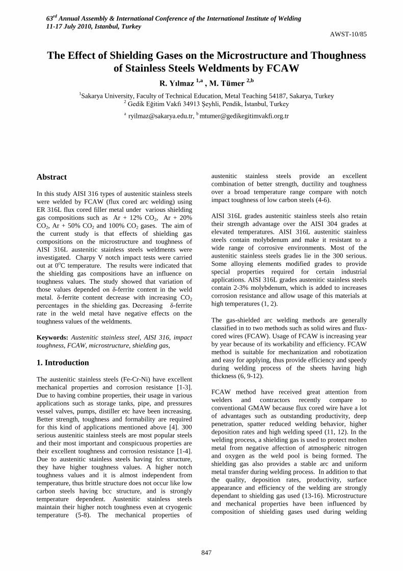
The plates were joined firstly in the root pass later
second pass and then third cover pass, respectively. A
schematic diagram of welded plate is shown in Figure 1.
Welding process were carried out under four different
shielding gases such as 12% CO2 + 88% Ar (C1), 20%
CO2 + 80% Ar (C2), 50% CO2 +50% Ar (C3) and 100%
CO2 (C4) with gas flow rate of 20 lt/min. Interpasses
temperature keeps below 150oC due to lower thermal
conductivity of austenitic stainless steels.
Figure 1. Scheme of joint preparation of FCAW weld, V shaped
grove design and number of welding passes
The welding parameters were shown in Table 2. The
welding parameters used were selected according to
suggestions of product catalogue prepared by flux cored
wire consumable producer and experiences obtained
earlier. As seen from the table, welding current and
voltage were between 185-222 and 24-26 volt
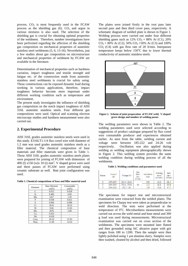
respectively. Oscillation was also applied during
welding as welding equipment photographically shown
in Figure 2. This welding system provides the same
welding condition during welding process of all the
weldments.
Table 2. Welding conditions and parameters used
The specimens for impact test and microstructural
examination were extracted from the welded plates. The
specimens for Charpy test were taken as perpendicular to
weld direction. The tests were performed at the
temperature of 0oC. Microhardness measurements were
carried out across the weld metal and base metal and 300
g load was used during measurements. Microstructural
examination was carried out on cross section of the
weldments. The specimens were mounted later flatted
and then grounded using SiC abrasive paper with grit
ranges from 180 to 1200. Then the sample were then
lightly polished using 1 μm alumina slurry. Samples were
then washed, cleaned by alcohol and then dried, followed
63rd
Annual Assembly & International Conference of the International Institute of Welding
11-17 July 2010, Istanbul, Turkey
AWST-10/85
849
by electrolytic etching in 10 % oxalic acid at 9v for 30 s.
Optical examination samples were performed using a
Nikon Elipse L 150 model optical microscopy. Scanning
electron microscopy (SEM) was used for examination of
fracture surface after impact test. Chemical composition
of weld metal was determined by using Faundry Master
Spektrometre. Ferrite numbers of the weld metal were
measured using ferrite-scope equipment.
Figure 2. The assembly of welding equipments, preparation and
performing of the welding
3. Results and discussion
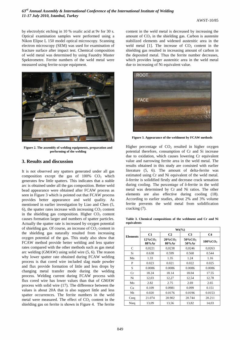
It is not observed any spatters generated under all gas
composition except the gas of 100% CO2 which
generates few little spatters. This indicates that a stable
arc is obtained under all the gas composition. Better weld
bead appearance were obtained after FCAW process as
seen in Figure 3 which is pointed out that FCAW process
provides better appearance and weld quality. As
mentioned in earlier investigation by Liao and Chen (5,
6), the spatter rates increase with increasing CO2 content
in the shielding gas composition. Higher CO2 content
causes formation larger and numbers of spatter particles.
Actually the spatter rate is increased by oxygen potential
of shielding gas. Of course, an increase of CO2 content in
the shielding gas naturally resulted from increasing
oxygen potential of the gas. This study also show that
FCAW method provide better welding and less spatter
rates compared with the other methods such as gas metal
arc welding (GMAW) using solid wire (5, 6). The reason
why lower spatter rate obtained during FCAW welding
process is that cored wire included slag made powder
and flux provide formation of little and less drops by
changing metal transfer mode during the welding
process. Welding current during FCAW process with
flux cored wire has lower values than that of GMAW
process with solid wire (17). The difference between the
values is about 20A that is also support little and less
spatter occurrences. The ferrite numbers in the weld
metal were measured. The effect of CO2 content in the
shielding gas on ferrite is shown in Figure 4. The ferrite
content in the weld metal is decreased by increasing the
amount of CO2 in the shielding gas. Carbon is austenite
stabilized elements and widened austenitic area in the
weld metal [1]. The increase of CO2 content in the
shielding gas resulted in increasing amount of carbon in
the deposited metal. Thus the ferrite number decreases,
which provides larger austenitic area in the weld metal
due to increasing of Ni equivalent value.
Figure 3. Appearance of the weldment by FCAW methods
Higher percentage of CO2 resulted in higher oxygen
potential therefore, consumption of Cr and Si increase
due to oxidation, which causes lowering Cr equivalent
value and narrowing ferrite area in the weld metal. The
results obtained in this study are consisted with earlier
literature (5, 6). The amount of delta-ferrite was
estimated using Cr and Ni equivalent of the weld metal.
δ-ferrite is solidified firstly and decrease crack sensation
during cooling. The percentage of δ-ferrite in the weld
metal was determined by Cr and Ni ratios. The other
elements are also effective during cooling (18).
According to earlier studies, about 2% and 3% volume
ferrite prevents the weld metal from solidification
cracking (7).
Table 3. Chemical compositions of the weldment and Cr and Ni
equivalents
Elements
Wt(%)
C1 C2 C3 C4
12%CO2
88%Ar
20%CO2
80%Ar
50%CO2
50%Ar 100%CO2
C 0,0221 0,0238 0,0246 0,0263
Si 0.638 0.599 0.568 0.544
Mn 1.33 1.35 1.24 1.16
P 0.023 0.021 0.022 0.025
S 0.0086 0.0086 0.0086 0.0086
Cr 18.24 18.14 18.04 17.55
Ni 12,03 12,27 12,54 12,78
Mo 2.82 2.75 2.69 2.65
Cu 0.109 0.0981 0.099 0.151
Nb 0.020 0.0176 0.0196 0.0153
Creq 21.074 20.902 20.744 20.211
Nieq 13,09 13,56 13,82 14,03
850
On the other hand, ferrite number of 4 is preferable for
preventing hot cracking during the cooling of the weld
metal. Sometimes, cracks may be seen in deep and
narrow of weld metal during usage of the welding
methods having higher heat input (16). The measured
chemical composition of the weld metal is listed in Table
3.
Figure 4. The affection of CO2 in the gas composition on Nieq ve
delta-ferrite values
As seen from the table, carbon and nickel content in the
weld metal increase with increasing of the CO2 content in
the shielding gas. It is well known that nickel and carbon
are strong austenite stabilize elements. Therefore, the
effect of CO2 increase resulted in decreasing Creq. on the
other hand, increasing of Nieq. In addition to that, an
increase of CO2 percentage in the gas increases
consumption of Cr, Si and Mn (4).
Figure 5. Variation of % wt content of ferrite in the weld metal
The amount of δ-ferrite in the weld metal is calculated
using the composition of base and filler metal according
to Creq and Nieq WRC-92 diagram. The calculation of δ-
ferrite ratio is arrange from 4,2 % to 9,5 % however,
those are estimated values. Ferrite-scope apparatus were
used for measurement of ferrite content in the weld
metal. The amount of δ-ferrite was measured in every
single pass of the weldments.
Table 4. %wt ferrite amount of the weld metal obtained by
ferrite-scope measurements.
Ferrite Content
Shielding
Gases WM (Left)
1. pass 2. pass 3. pass Av.
C1 12,5 12,3 12,7 12,5
C2 11,7 12,1 11,9 11,9
C3 10,9 11,2 11,7 11,3
C4 6,7 9,0 8,8 8,2
WM (Mid)
1. pass 2. pass 3. pass Av.
C1 14,2 12,1 15,1 13,8
C2 12,0 12,3 12,7 12,3
C3 11,6 12,4 11,8 11,9
C4 6,1 8,5 11,3 8,6
WM (Right)
1. pass 2. pass 3. pass Av.
C1 10,9 10,6 13,2 11,6
C2 10,5 10,9 11,0 10,8
C3 7,1 8,2 8,8 8,0
C4 6,2 7,6 7,8 7,2
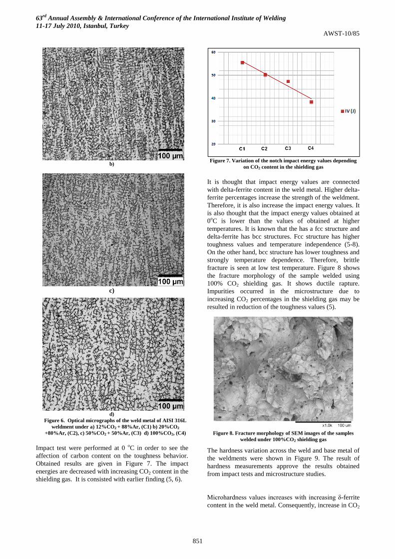
The results are listed in Table 4. Figure 5 also shows that
delta-ferrite percentage in the weld metal changes
depending on the content of carbon in the shielding gas.
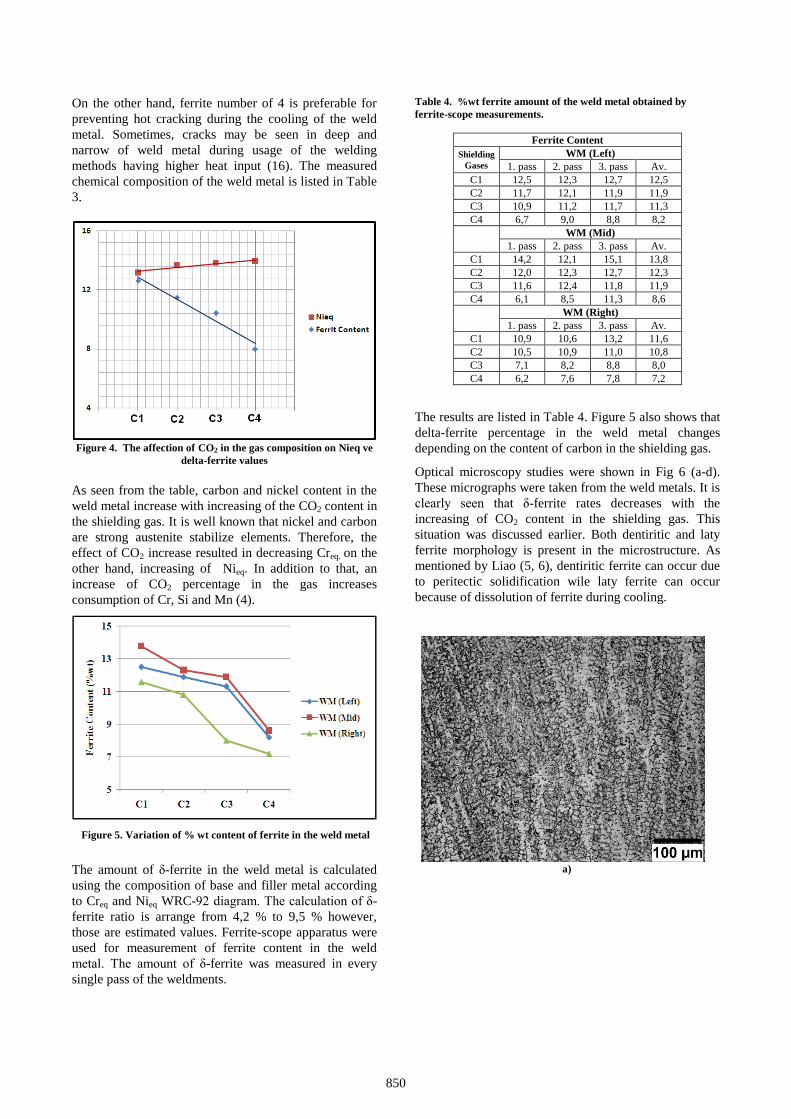
Optical microscopy studies were shown in Fig 6 (a-d).
These micrographs were taken from the weld metals. It is
clearly seen that δ-ferrite rates decreases with the
increasing of CO2 content in the shielding gas. This
situation was discussed earlier. Both dentiritic and laty
ferrite morphology is present in the microstructure. As
mentioned by Liao (5, 6), dentiritic ferrite can occur due
to peritectic solidification wile laty ferrite can occur
because of dissolution of ferrite during cooling.
a)
63rd
Annual Assembly & International Conference of the International Institute of Welding
11-17 July 2010, Istanbul, Turkey
AWST-10/85
851
b)
c)
d)
Figure 6. Optical micrographs of the weld metal of AISI 316L
weldment under a) 12%CO2 + 88%Ar, (C1) b) 20%CO2
+80%Ar, (C2), c) 50%CO2 + 50%Ar, (C3) d) 100%CO2, (C4)
Impact test were performed at 0 oC in order to see the
affection of carbon content on the toughness behavior.
Obtained results are given in Figure 7. The impact
energies are decreased with increasing CO2 content in the
shielding gas. It is consisted with earlier finding (5, 6).
Figure 7. Variation of the notch impact energy values depending
on CO2 content in the shielding gas
It is thought that impact energy values are connected
with delta-ferrite content in the weld metal. Higher delta-
ferrite percentages increase the strength of the weldment.
Therefore, it is also increase the impact energy values. It
is also thought that the impact energy values obtained at
0oC is lower than the values of obtained at higher
temperatures. It is known that the has a fcc structure and
delta-ferrite has bcc structures. Fcc structure has higher
toughness values and temperature independence (5-8).
On the other hand, bcc structure has lower toughness and
strongly temperature dependence. Therefore, brittle
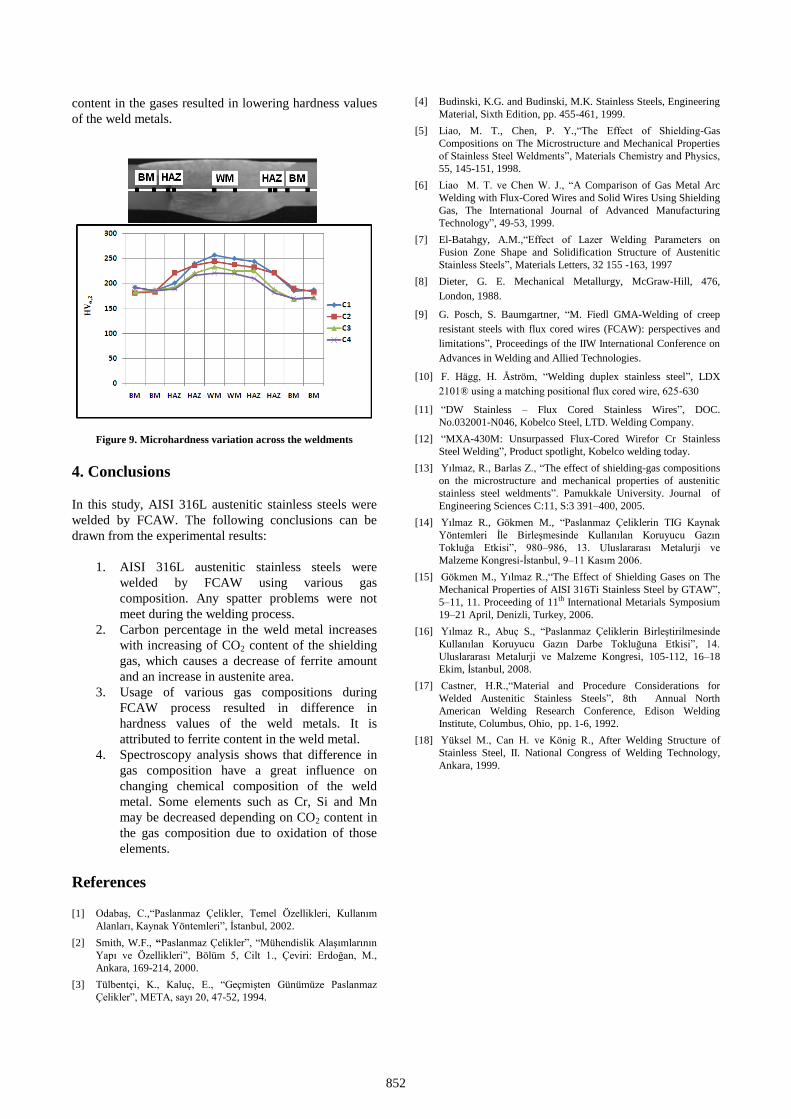
fracture is seen at low test temperature. Figure 8 shows
the fracture morphology of the sample welded using
100% CO2 shielding gas. It shows ductile rapture.
Impurities occurred in the microstructure due to
increasing CO2 percentages in the shielding gas may be
resulted in reduction of the toughness values (5).
Figure 8. Fracture morphology of SEM images of the samples
welded under 100%CO2 shielding gas
The hardness variation across the weld and base metal of
the weldments were shown in Figure 9. The result of
hardness measurements approve the results obtained
from impact tests and microstructure studies.
Microhardness values increases with increasing δ-ferrite
content in the weld metal. Consequently, increase in CO2
852
content in the gases resulted in lowering hardness values
of the weld metals.
Figure 9. Microhardness variation across the weldments
4. Conclusions
In this study, AISI 316L austenitic stainless steels were
welded by FCAW. The following conclusions can be
drawn from the experimental results:
1. AISI 316L austenitic stainless steels were
welded by FCAW using various gas
composition. Any spatter problems were not
meet during the welding process.
2. Carbon percentage in the weld metal increases
with increasing of CO2 content of the shielding
gas, which causes a decrease of ferrite amount
and an increase in austenite area.
3. Usage of various gas compositions during
FCAW process resulted in difference in
hardness values of the weld metals. It is
attributed to ferrite content in the weld metal.
4. Spectroscopy analysis shows that difference in
gas composition have a great influence on
changing chemical composition of the weld
metal. Some elements such as Cr, Si and Mn
may be decreased depending on CO2 content in
the gas composition due to oxidation of those
elements.
References
[1] Odabaş, C.,“Paslanmaz Çelikler, Temel Özellikleri, Kullanım
Alanları, Kaynak Yöntemleri”, İstanbul, 2002.
[2] Smith, W.F., “Paslanmaz Çelikler”, “Mühendislik Alaşımlarının
Yapı ve Özellikleri”, Bölüm 5, Cilt 1., Çeviri: Erdoğan, M.,
Ankara, 169-214, 2000.
[3] Tülbentçi, K., Kaluç, E., “Geçmişten Günümüze Paslanmaz
Çelikler”, META, sayı 20, 47-52, 1994.
[4] Budinski, K.G. and Budinski, M.K. Stainless Steels, Engineering
Material, Sixth Edition, pp. 455-461, 1999.
[5] Liao, M. T., Chen, P. Y.,“The Effect of Shielding-Gas
Compositions on The Microstructure and Mechanical Properties
of Stainless Steel Weldments”, Materials Chemistry and Physics,
55, 145-151, 1998.
[6] Liao M. T. ve Chen W. J., “A Comparison of Gas Metal Arc
Welding with Flux-Cored Wires and Solid Wires Using Shielding
Gas, The International Journal of Advanced Manufacturing
Technology”, 49-53, 1999.
[7] El-Batahgy, A.M.,“Effect of Lazer Welding Parameters on
Fusion Zone Shape and Solidification Structure of Austenitic
Stainless Steels”, Materials Letters, 32 155 -163, 1997
[8] Dieter, G. E. Mechanical Metallurgy, McGraw-Hill, 476,
London, 1988.
[9] G. Posch, S. Baumgartner, “M. Fiedl GMA-Welding of creep
resistant steels with flux cored wires (FCAW): perspectives and
limitations”, Proceedings of the IIW International Conference on
Advances in Welding and Allied Technologies.
[10] F. Hägg, H. Åström, “Welding duplex stainless steel”, LDX
2101® using a matching positional flux cored wire, 625-630
[11] “DW Stainless – Flux Cored Stainless Wires”, DOC.
No.032001-N046, Kobelco Steel, LTD. Welding Company.
[12] “MXA-430M: Unsurpassed Flux-Cored Wirefor Cr Stainless
Steel Welding”, Product spotlight, Kobelco welding today.
[13] Yılmaz, R., Barlas Z., “The effect of shielding-gas compositions
on the microstructure and mechanical properties of austenitic
stainless steel weldments”. Pamukkale University. Journal of
Engineering Sciences C:11, S:3 391–400, 2005.
[14] Yılmaz R., Gökmen M., “Paslanmaz Çeliklerin TIG Kaynak
Yöntemleri İle Birleşmesinde Kullanılan Koruyucu Gazın
Tokluğa Etkisi”, 980–986, 13. Uluslararası Metalurji ve
Malzeme Kongresi-İstanbul, 9–11 Kasım 2006.
[15] Gökmen M., Yılmaz R.,“The Effect of Shielding Gases on The
Mechanical Properties of AISI 316Ti Stainless Steel by GTAW”,
5–11, 11. Proceeding of 11th International Metarials Symposium
19–21 April, Denizli, Turkey, 2006.
[16] Yılmaz R., Abuç S., “Paslanmaz Çeliklerin Birleştirilmesinde
Kullanılan Koruyucu Gazın Darbe Tokluğuna Etkisi”, 14.
Uluslararası Metalurji ve Malzeme Kongresi, 105-112, 16–18
Ekim, İstanbul, 2008.
[17] Castner, H.R.,“Material and Procedure Considerations for
Welded Austenitic Stainless Steels”, 8th Annual North
American Welding Research Conference, Edison Welding
Institute, Columbus, Ohio, pp. 1-6, 1992.
[18] Yüksel M., Can H. ve König R., After Welding Structure of
Stainless Steel, II. National Congress of Welding Technology,
Ankara, 1999.