Embed Size (px)
Citation preview
Fourth International Symposium on Marine Propulsors smp’15, Austin, Texas, USA, June 2015
The Effect of Sheet Cavitation on the Blade Spindle Torque of a Controllable Pitch Propeller
Aibing Liu1, Jie Dang
2, Qingcheng Xie
1 and Juxi Hu
1
1Shanghai Marine Equipment Research Institute (SMERI)
2Maritime Research Institute Netherlands (MARIN)
ABSTRACT
In order to help the design of a Controllable Pitch Propeller
(CPP) and to prevent too high blade actuating pressure in
the hub, a 5-bladed CPP model with modern skewed blade
design has been used to measure its hydrodynamic blade
spindle torque at various pitch settings. Tests have been
carried out both in non-cavitating and cavitating conditions
in the Deep Water Towing Tank (DT) and the
Depressurized Wave Basin (DWB) at the Maritime
Research Institute Netherlands (MARIN), respectively. This
paper investigates the variations of the spindle torque as
function of advance ratios and pitch settings. Emphasis is
put on the effect of sheet cavitation on the blade spindle
torque. Primary CFD calculations have been performed to
calculate the blade spindle torque in open water, which are
compared to the test results.
Keywords
Spindle torque, Cavitation, Controllable pitch propeller.
1 INTRODUCTION
Propeller blade spindle torque plays an important role in the
operation of CPPs at various operating conditions. A well
designed CPP should have low blade spindle torque in
general and should be able to operate at the most critical
conditions with respect to the spindle torque, for instance
during the acceleration of the ship from zero speed to full
speed, and during a crash stop of the ship.
In practice, knowledge of the propeller blade spindle torque
is usually obtained from the feedback from full scale trials
on the actuating pressure measured at various actual
operating conditions of the ship. However the results are
often not accurate enough, considering the pressure losses
in the oil pipe. In addition, the frictional spindle torque from
the pitch change mechanism is difficult to be split from the
total spindle torque in order to derive the hydrodynamic and
centrifugal spindle torques.
Compared to the thrust, the torque and the efficiency of a
CPP, calculation or measurement in model scale of the
blade spindle torque is difficult. In the calculations, the
pressure distribution of each section of a blade in normal
and off-design conditions cannot be accurately predicted
yet. During a model test, the centrifugal spindle torque is
not easy to be separated from the hydrodynamic spindle
torque. That could be the reason why the work on blade
spindle torque is scarce. Limited publications are available,
though the research has started already in the 1950s.
As early as in 1964, Miller investigated the thrust and
torque characteristics as well as both the hydrodynamic and
centrifugal blade spindle torques at ahead pitch settings for
four CPPs in a water tunnel. Hansen (1967) then
experimentally studied the blade spindle torque for five
CPPs at both positive and negative advance ratios and for
both ahead and astern pitch settings, and found the optimum
spindle axis for the un-cambered NACA 66-mod blade
sections. Denny and Nelka (1972) measured the four-
quadrant open water characteristics of a five-bladed CPP,
including their blade spindle torques. Their studies showed
that the Reynolds number had a strong effect on the blade
spindle torque, and concluded that the chord-wise pressure
distribution on a propeller blade might have been changed
both in shape and magnitude due to the changes of the
resultant flow velocity onto the blade.
Denny and Nelka (1972) studied also cavitation effects on
the blade spindle torque and suggested that cavitation has a
very significant effect on the blade spindle torque, though
very limited data were obtained due to the transducers’
ability. In the 1970s, spindle torque measurements on a
three-bladed CPP in cavitating and non-cavitating
conditions were conducted at the Marine Design &
Research Institute of China (MARIC). Due to the relatively
large contribution of the friction from the pitch change
mechanism to the measured spindle torque, the test results
were however rough and could only be used qualitatively.
Pronk (1980) investigated the spindle torque of several
propellers with different blade area ratios and skews at then-
called the ‘Depressurized Towing Tank’ at MARIN (now
DWB), in which the cavitation effects were studied in
behind condition. Studies on the propeller blade spindle
torque in behind conditions were also carried out recently
by Jessup et al. (2009).
In addition to the studies on the cavitation effect on blade
spindle torque, Koushan et al. (2011) measured blade
spindle torque for a pulling thruster in ventilated conditions
although propeller blade ventilation should be avoided in
general, and observed that the spindle torque changes sign
from positive to negative at high advance ratios. In recent
years, Computational Fluid Dynamics (CFD) started to play
an important role in predicting the blade hydrodynamic
spindle torque. Funeno et al. (2013) presented some results
for two CPPs by CFD and compared the results to the test
results in open water. Good agreement has been achieved.
In the past, testing of CPP hydrodynamic characteristics
was conducted point by point, that is, water velocity and
shaft rotational rate are kept constant during the
measurements. Testing of two quadrant characteristics of
CPPs is labor-intensive. Besides, cavitation tests of blade
spindle torque are often conducted in a cavitation tunnel, in
which blockage effects could not be eliminated.
Fortunately, systematic measurements have been made
available recently from the Wageningen C- and D-series
propellers at non-cavitating conditions (Dang et al., 2013).
Testing in the DWB of MARIN, which has a cross section
of 18m wide and 8m deep, can avoid the blockage effect
completely.
In order to help the design of a CPP and to prevent too high
propeller blade actuating pressure in the hub, one typical
modern designed CPP with 5 blades has been measured in
uniform flow for its hydrodynamic blade spindle torque at
various pitch settings, both in non-cavitating and cavitating
conditions at MARIN’s DT and DWB, respectively. CFD
techniques were used to calculate the blade spindle torque
in open water primarily. The results are then compared to
the test results and discussed in this paper.
2 TEST SET-UP AND TEST PROCEDURES
2.1 TEST SET-UP AND TRANSDUCERS
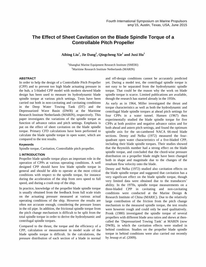
The test set-up is sketched in Figure 1, which has a very
slender pod and a thin strut.
Figure 1: Sketch of the test set-up.
On the shaft very close to the propeller, a transducer to
measure the propeller shaft thrust and torque was installed.
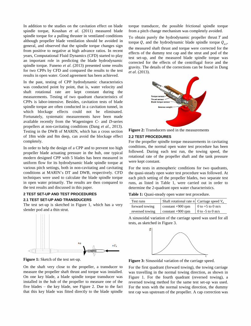
On one key blade, a blade spindle torque transducer was
installed in the hub of the propeller to measure one of the
five blades – the key blade, see Figure 2. Due to the fact
that this key blade was fitted directly to the blade spindle
torque transducer, the possible frictional spindle torque
from a pitch change mechanism was completely avoided.
To obtain purely the hydrodynamic propeller thrust and
torque , and the hydrodynamic blade spindle torque ℎ,
the measured shaft thrust and torque were corrected for the
effects of the dummy test cap and the strut and pod of the
test set-up, and the measured blade spindle torque was
corrected for the effects of the centrifugal force and the
gravity. The details of the corrections can be found in Dang
et al. (2013).
Figure 2: Transducers used in the measurements
2.2 TEST PROCEDURES
For the propeller spindle torque measurements in cavitating
conditions, the normal open water test procedure has been
followed. During each test run, the towing speed, the
rotational rate of the propeller shaft and the tank pressure
were kept constant.
For the tests in atmospheric conditions for two quadrants,
the quasi-steady open water test procedure was followed. At
each pitch setting of the propeller blades, two separate test
runs, as listed in Table 1, were carried out in order to
determine the 2-quadrant open water characteristics.
Table 1: Quasi-steady open water test procedure.
Test runs Shaft rotational rate n Carriage speed Va
forward towing
reversed towing
constant +900 rpm
constant +900 rpm
0 to +5 to 0 m/s
0 to -5 to 0 m/s
A sinusoidal variation of the carriage speed was used for all
tests, as sketched in Figure 3.
Figure 3: Sinusoidal variation of the carriage speed.
For the first quadrant (forward towing), the towing carriage
was travelling in the normal towing direction, as shown in
Figure 1. For the fourth quadrant (reversed towing), a
reversed towing method for the same test set-up was used.
For the tests with the normal towing direction, the dummy
test cap was upstream of the propeller. A cap correction was
applied to the test results. For the tests in the reversed
towing direction, the dummy cap was in the blocked flow
region of the propeller. No test cap correction was applied.
The wake of the pod and strut of the test set-up for the
reversed towing tests was corrected too.
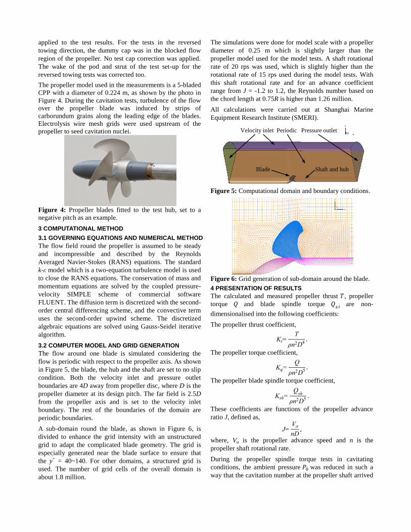
The propeller model used in the measurements is a 5-bladed
CPP with a diameter of 0.224 m, as shown by the photo in
Figure 4. During the cavitation tests, turbulence of the flow
over the propeller blade was induced by strips of
carborundum grains along the leading edge of the blades.
Electrolysis wire mesh grids were used upstream of the
propeller to seed cavitation nuclei.
Figure 4: Propeller blades fitted to the test hub, set to a
negative pitch as an example.
3 COMPUTATIONAL METHOD
3.1 GOVERNING EQUATIONS AND NUMERICAL METHOD
The flow field round the propeller is assumed to be steady
and incompressible and described by the Reynolds
Averaged Navier-Stokes (RANS) equations. The standard
k-ε model which is a two-equation turbulence model is used
to close the RANS equations. The conservation of mass and
momentum equations are solved by the coupled pressure-
velocity SIMPLE scheme of commercial software
FLUENT. The diffusion term is discretized with the second-
order central differencing scheme, and the convective term
uses the second-order upwind scheme. The discretized
algebraic equations are solved using Gauss-Seidel iterative
algorithm.
3.2 COMPUTER MODEL AND GRID GENERATION
The flow around one blade is simulated considering the
flow is periodic with respect to the propeller axis. As shown
in Figure 5, the blade, the hub and the shaft are set to no slip
condition. Both the velocity inlet and pressure outlet
boundaries are 4D away from propeller disc, where D is the
propeller diameter at its design pitch. The far field is 2.5D
from the propeller axis and is set to the velocity inlet
boundary. The rest of the boundaries of the domain are
periodic boundaries.
A sub-domain round the blade, as shown in Figure 6, is
divided to enhance the grid intensity with an unstructured
grid to adapt the complicated blade geometry. The grid is
especially generated near the blade surface to ensure that
the y+ = 40~140. For other domains, a structured grid is
used. The number of grid cells of the overall domain is
about 1.8 million.
The simulations were done for model scale with a propeller
diameter of 0.25 m which is slightly larger than the
propeller model used for the model tests. A shaft rotational
rate of 20 rps was used, which is slightly higher than the
rotational rate of 15 rps used during the model tests. With
this shaft rotational rate and for an advance coefficient
range from J = -1.2 to 1.2, the Reynolds number based on
the chord length at 0.75R is higher than 1.26 million.
All calculations were carried out at Shanghai Marine
Equipment Research Institute (SMERI).
Figure 5: Computational domain and boundary conditions.
Figure 6: Grid generation of sub-domain around the blade.
4 PRESENTATION OF RESULTS
The calculated and measured propeller thrust , propeller
torque and blade spindle torque ℎ are non-
dimensionalised into the following coefficients:
The propeller thrust coefficient,
The propeller torque coefficient,
The propeller blade spindle torque coefficient,
These coefficients are functions of the propeller advance
ratio J, defined as,
where, Va is the propeller advance speed and n is the
propeller shaft rotational rate.
During the propeller spindle torque tests in cavitating
conditions, the ambient pressure was reduced in such a
way that the cavitation number at the propeller shaft arrived
Periodic Pressure outlet Velocity inlet
Blade Shaft and hub
at a prescribed value, where the cavitation number was
defined as,
All thrust and torque coefficients in the figures below are
normalized by their values for the pitch deflection of α=1.1
at J=0, measured at atmospheric condition.
5 RESULTS AND DISCUSSIONS
5.1 OPEN WATER TEST RESULTS AND NUMERICAL
VALIDATION
Figures 7 to 9 show the test results of the two-quadrant
hydrodynamic thrust coefficient , torque coefficient
and spindle torque coefficient , compared with the
calculation results in open water, in which α (in degrees)
denotes the blade deflection angle from its design pitch.
It can be seen from the figures that the calculated and
coincide very well with the test results for all , except
for the pitch deflection when the is close to 0. In
the fourth quadrant, the numerical method shows less good
results. It seems that for larger pitch settings, the calculation
underestimates the results. This may be caused by the
complicated flows when the blade pitch is positive while the
advance velocity is negative, which corresponds to the crash
stop ahead condition of a ship.
Figure 7: Measured and calculated vs. J.
For the blade spindle torque, the CFD results did not agree
very well with the test results, however it follows the trend
of the variation and can be used to estimate spindle torque
in a rough manner.
As will be shown later, cavitation has a great effect on the
blade spindle torque. The numerical simulation with CFD in
open water without cavitation may not show the same
effect, however it may help to understand the phenomenon.
The left part of Figure 10 shows an area on the blade
suction side where the pressure is lower than the vapor
pressure for the condition at , and . It is natural to speculate that this area will cavitate
with a sheet cavity somewhat larger than the low pressure
area. A comparison can be made to the cavity pattern which
is shown in the photo on the right-hand side of Figure 10.
Indeed the cavitation pattern and its area are very similar to
the low pressure area. The estimation is however intuitive
and not accurate enough. In reality, the cavitation will
change the flow pattern and modify the pressure distribution
along the blade section profiles. In order to investigate its
effects on the blade spindle torque, a cavitation model
should be incorporated into the CFD simulation. This work
is left to be done in the near future.
Figure 8: Measured and calculated vs. J.
Figure 9: Measured and calculated vs. J.
(a) area with pressure lower than
vapour pressure by CFD
(b) cavitation pattern on the blade
from the test
Figure 10: Comparison of cavitation area for ,
and between calculation and test.
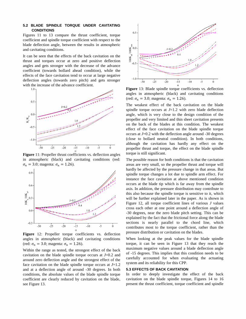
5.2 BLADE SPINDLE TORQUE UNDER CAVITATING
CONDITIONS
Figures 11 to 13 compare the thrust coefficient, torque
coefficient and spindle torque coefficient with respect to the
blade deflection angle, between the results in atmospheric
and cavitating conditions.
It can be seen that the effects of the back cavitation on the
thrust and torques occur at zero and positive deflection
angles and gets stronger with the decrease of the advance
coefficient (towards bollard ahead condition), while the
effects of the face cavitation tend to occur at large negative
deflection angles (towards zero pitch) and gets stronger
with the increase of the advance coefficient.
Figure 11: Propeller thrust coefficients vs. deflection angles
in atmospheric (black) and cavitating conditions (red:
; magenta: ).
Figure 12: Propeller torque coefficients vs. deflection
angles in atmospheric (black) and cavitating conditions
(red: ; magenta: ).
Within the range as tested, the strongest effect of the back
cavitation on the blade spindle torque occurs at J=0.2 and
around zero deflection angle and the strongest effect of the
face cavitation on the blade spindle torque occurs at J=1.2
and at a deflection angle of around -30 degrees. In both
conditions, the absolute values of the blade spindle torque
coefficient are clearly reduced by cavitation on the blade,
see Figure 13.
Figure 13: Blade spindle torque coefficients vs. deflection
angles in atmospheric (black) and cavitating conditions
(red: ; magenta: ).
The weakest effect of the back cavitation on the blade
spindle torque occurs at J=1.2 with zero blade deflection
angle, which is very close to the design condition of the
propeller and very limited and thin sheet cavitation presents
on the back of the blades at this condition. The weakest
effect of the face cavitation on the blade spindle torque
occurs at J=0.2 with the deflection angle around -30 degrees
(close to bollard neutral condition). In both conditions,
although the cavitation has hardly any effect on the
propeller thrust and torque, the effect on the blade spindle
torque is still significant.
The possible reason for both conditions is that the cavitation
areas are very small, so the propeller thrust and torque will
hardly be affected by the pressure change in that areas. But
spindle torque changes a lot due to spindle arm effect. For
instance the face cavitation at above mentioned condition
occurs at the blade tip which is far away from the spindle
axis. In addition, the pressure distribution may contribute to
this also because the spindle torque is sensitive to it, which
will be further explained later in the paper. As is shown in
Figure 12, all torque coefficient lines of various J values
cross each other at one point around a deflection angle of
-30 degrees, near the zero blade pitch setting. This can be
explained by the fact that the frictional force along the blade
sections is nearly parallel to the chord line, which
contributes most to the torque coefficient, rather than the
pressure distribution or cavitation on the blades.
When looking at the peak values for the blade spindle
torque, it can be seen in Figure 13 that they reach the
maximum negative values around a blade deflection angle
of -15 degrees. This implies that this condition needs to be
carefully accounted for when evaluating the actuating
system and its reliability for this CPP.
5.3 EFFECTS OF BACK CAVITATION
In order to deeply investigate the effect of the back
cavitation on the blade spindle torque, Figures 14 to 16
present the thrust coefficient, torque coefficient and spindle
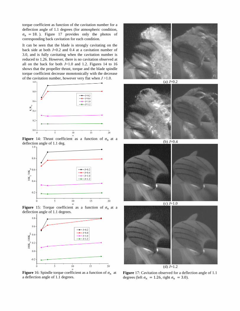
torque coefficient as function of the cavitation number for a
deflection angle of 1.1 degrees (for atmospheric condition,
). Figure 17 provides only the photos of
corresponding back cavitation for each condition.
It can be seen that the blade is strongly cavitating on the
back side at both J=0.2 and 0.4 at a cavitation number of
3.0, and is fully cavitating when the cavitation number is
reduced to 1.26. However, there is no cavitation observed at
all on the back for both J=1.0 and 1.2. Figures 14 to 16
shows that the propeller thrust, torque and the blade spindle
torque coefficient decrease monotonically with the decrease
of the cavitation number, however very flat when J >1.0.
Figure 14: Thrust coefficient as a function of at a
deflection angle of 1.1 deg.
Figure 15: Torque coefficient as a function of at a
deflection angle of 1.1 degrees.
Figure 16: Spindle torque coefficient as a function of at
a deflection angle of 1.1 degrees.
(a) J=0.2
(b) J=0.4
(c) J=1.0
(d) J=1.2
Figure 17: Cavitation observed for a deflection angle of 1.1
degrees (left , right ).
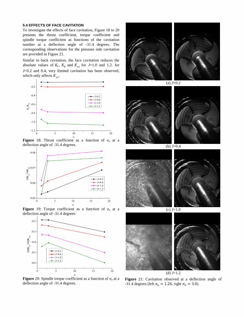
5.4 EFFECTS OF FACE CAVITATION
To investigate the effects of face cavitation, Figure 18 to 20
presents the thrust coefficient, torque coefficient and
spindle torque coefficient as functions of the cavitation
number at a deflection angle of -31.4 degrees. The
corresponding observations for the pressure side cavitation
are provided in Figure 21.
Similar to back cavitation, the face cavitation reduces the
absolute values of , and ℎ for J=1.0 and 1.2. for
J=0.2 and 0.4, very limited cavitation has been observed,
which only affects ℎ.
Figure 18: Thrust coefficient as a function of σn at a
deflection angle of -31.4 degrees.
Figure 19: Torque coefficient as a function of σn at a
deflection angle of -31.4 degrees.
Figure 20: Spindle torque coefficient as a function of σn at a
deflection angle of -31.4 degrees.
(a) J=0.2
(b) J=0.4
(c) J=1.0
(d) J=1.2
Figure 21: Cavitation observed at a deflection angle of
-31.4 degrees (left , right ).
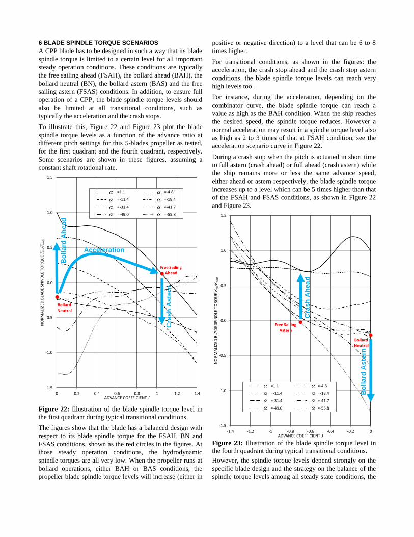
6 BLADE SPINDLE TORQUE SCENARIOS
A CPP blade has to be designed in such a way that its blade
spindle torque is limited to a certain level for all important
steady operation conditions. These conditions are typically
the free sailing ahead (FSAH), the bollard ahead (BAH), the
bollard neutral (BN), the bollard astern (BAS) and the free
sailing astern (FSAS) conditions. In addition, to ensure full
operation of a CPP, the blade spindle torque levels should
also be limited at all transitional conditions, such as
typically the acceleration and the crash stops.
To illustrate this, Figure 22 and Figure 23 plot the blade
spindle torque levels as a function of the advance ratio at
different pitch settings for this 5-blades propeller as tested,
for the first quadrant and the fourth quadrant, respectively.
Some scenarios are shown in these figures, assuming a
constant shaft rotational rate.
Figure 22: Illustration of the blade spindle torque level in
the first quadrant during typical transitional conditions.
The figures show that the blade has a balanced design with
respect to its blade spindle torque for the FSAH, BN and
FSAS conditions, shown as the red circles in the figures. At
those steady operation conditions, the hydrodynamic
spindle torques are all very low. When the propeller runs at
bollard operations, either BAH or BAS conditions, the
propeller blade spindle torque levels will increase (either in
positive or negative direction) to a level that can be 6 to 8
times higher.
For transitional conditions, as shown in the figures: the
acceleration, the crash stop ahead and the crash stop astern
conditions, the blade spindle torque levels can reach very
high levels too.
For instance, during the acceleration, depending on the
combinator curve, the blade spindle torque can reach a
value as high as the BAH condition. When the ship reaches
the desired speed, the spindle torque reduces. However a
normal acceleration may result in a spindle torque level also
as high as 2 to 3 times of that at FSAH condition, see the
acceleration scenario curve in Figure 22.
During a crash stop when the pitch is actuated in short time
to full astern (crash ahead) or full ahead (crash astern) while
the ship remains more or less the same advance speed,
either ahead or astern respectively, the blade spindle torque
increases up to a level which can be 5 times higher than that
of the FSAH and FSAS conditions, as shown in Figure 22
and Figure 23.
Figure 23: Illustration of the blade spindle torque level in
the fourth quadrant during typical transitional conditions.
However, the spindle torque levels depend strongly on the
specific blade design and the strategy on the balance of the
spindle torque levels among all steady state conditions, the
Bollard Neutral
Free Sailing Ahead
-1.5
-1.0
-0.5
0.0
0.5
1.0
1.5
0 0.2 0.4 0.6 0.8 1 1.2 1.4
NO
RM
ALI
ZED
BLA
DE
SPIN
DLE
TO
RQ
UE
Ksh
/Ksh
0
ADVANCE COEFFICIENT J
=1.1 =-4.8
=-11.4 =-18.4
=-31.4 =-41.7
=-49.0 =-55.8
a a
a a
a a
a a
Bollard
Neutral
Free Sailing
Astern
-1.5
-1.0
-0.5
0.0
0.5
1.0
1.5
-1.4 -1.2 -1 -0.8 -0.6 -0.4 -0.2 0
NO
RM
ALI
ZED
BLA
DE
SPIN
DLE
TO
RQ
UE
Ksh
/Ksh
0
ADVANCE COEFFICIENT J
=1.1 =-4.8
=-11.4 =-18.4
=-31.4 =-41.7
=-49.0 =-55.8
a a
a a
a a
a a
Bo
llard
Ah
ead
Bo
llard
Aste
rn
Cra
sh
Aste
rn
Cra
sh
Ah
ead
Acceleration
transitional conditions and the variable shaft rotational rate
conditions. In addition, the centrifugal and frictional force,
which are related to the material and the mechanism of the
pitch actuating mechanism, play important roles too.
7 CONCLUSIONS AND FUTURE WORK
A typical CPP with 5 blades and with modern blade design
has been measured in uniform flow to determine its
hydrodynamic characteristics, including blade spindle
torque at various pitch settings both in cavitating and non-
cavitating conditions. A CFD technique was used primarily
to calculate the blade spindle torque in open water.
The below conclusions summarize the findings of the
present study:
- Within the test range of the blade pitch settings between
the design pitch and the zero pitch, the test results show
that the blade spindle torque is very sensitive to the
sheet cavitation on the propeller blades, both on the back
and on the face of the propeller blades. This is rather
different from the cavitation effects on the propeller
thrust and torque which are insensitive in general to a
small amount of sheet cavitation on the blades.
- The sheet cavitation on the back of the blades has only
strong influence on the propeller thrust and torque at the
design pitch setting when the advance ratio is low and
when the cavitation number is small, meaning close to
the bollard condition with a lot of cavitation on the
blades. However, its effect on the spindle torque is
significant for all advance ratios, even if at the J value
where only thin sheet cavitation is expected.
- The sheet cavitation on the face of the blades has strong
influence on the blade spindle torque at the zero pitch
setting and at high advance ratio, although the propeller
thrust and torque are not affected that much by the
cavitation on the face, indicating that the friction force
on the blade is dominant for the propeller torque rather
than the pressure distribution.
- A peak spindle torque value is found at high advance
ratio when the blade pitch setting is reduced to about
half of the design pitch setting, around a deflection angle
of -15 degrees for the present propeller, see Figure 13.
- Small sheet cavitation at the tip will not have effect on
the propeller thrust and torque but may have an effect on
the spindle torque coefficient due to the spindle arm
effect.
- CFD calculation results agree well with the propeller
thrust and torque coefficients from the tests when J >0,
but not for the blade spindle torque. Thus future work
needs to be done to improve the numerical method for
the blade spindle torque, including simulation of the
cavitating flow around the blade. The method need to be
improved and validated by model test results. The final
aim of developing the CFD technique is to make a
reliable tool with enough accuracy in order to replace
model tests which is expensive or in some situations
hard to perform.
ACKOWLEGEMENT
The authors would like to acknowledge the members who
conducted the tests at MARIN. Special thanks go to Prof.
C.J. Yang from Shanghai Jiao Tong University and Mr. J.H.
Allema from MARIN for reviewing this paper and their
valuable comments.
REFERENCES
Dang, J., van der Boom, H. and Ligtelijn, JTh., (2013). The
Wageningen C- and D-Series Propellers, Proceedings of
FAST’ 3, Amsterdam, Netherlands.
Denny, S.B. and Nelka, J.J., (1972). Blade Spindle Moment
on a Five-bladed Controllable-pitch Propeller, DTMB
report No. 3729.
Funeno, I., Pouw, C. and Bosman, R., (2013). Measurement
and Computations for Blade Spindle Torque of
Controllable Pitch Propellers in Open Water,
Proceedings of the Third International Symposium on
Marine Propulsors smp’13, Tasmania, Australia.
Hansen, E.O., (1967). Thrust and Blade Spindle Torque
Measurements of Five Controllable-Pitch Propeller
Designs for MSO 421, DTMB report No. 2325.
Jessup S., Donnelly M., McClintock I. and Carpenter S.
(2009). Measurements of Controllable Pitch Propeller
Blade Loads under Cavitating Conditions, Proceedings
of the First International Symposium on Marine
Propulsors, Trondheim, Norway, June.
Koushan, K., Spence, S. and Savio, L., (2011). Ventilated
Propeller Blade Loadings and Spindle Moment of a
Thruster in Calm Water and Waves, Proceedings of the
Second International Symposium on Marine Propulsors
smp’11, Hamburg, Germany.
Miller, M.L., (1964). Spindle Torque Tests of Four CRP
Propeller Blade Designs for MSO 421, DTMB report
No. 1837.
Pronk, C., (1980). Blade spindle torque and off-design
behavior of controllable pitch propellers, Dissertation to
the Technical University Delft, the Netherlands.


![Visualization of Unsteady Behavior of Cavitation in ... · cavitation state, transition-cavitation state, and super-cavitation state in the orifice throat [5]. Under relative high](https://img.pdfslide.us/doc/110x75/5b4f673e7f8b9a166e8c4c74/visualization-of-unsteady-behavior-of-cavitation-in-cavitation-state-transition-cavitation.jpg)


![Numerical Study on Cavitation Noise of Symmetrical Blade … 2018... · 2018-09-05 · Figure 1: The frequency ranges of cavitation noise for marine propellers (Seol, 2005)[12]. 2.2.Symmetrical](https://img.pdfslide.us/doc/110x75/5e3799c97446173dbf3be229/numerical-study-on-cavitation-noise-of-symmetrical-blade-2018-2018-09-05.jpg)