Embed Size (px)
Citation preview
IOP PUBLISHING SMART MATERIALS AND STRUCTURES
Smart Mater. Struct. 17 (2008) 055012 (13pp) doi:10.1088/0964-1726/17/5/055012
The effect of actuator bending on Lambwave displacement fields generated by apiezoelectric patchH Huang1,3, T Pamphile2 and M Derriso2
1 Department of Mechanical and Aerospace Engineering, University of Texas at Arlington,500 W First Street, WH211, Arlington, TX 76019, USA2 AFRL/RB, WPAFB, OH, USA
E-mail: [email protected]
Received 19 January 2008, in final form 11 July 2008Published 7 August 2008Online at stacks.iop.org/SMS/17/055012
AbstractA Lamb wave is a special type of elastic wave that is widely employed in structural healthmonitoring systems for damage detection. Recently, piezoelectric (piezo) patches have becomepopular for Lamb wave excitation and sensing because one piezo patch can serve as both theactuator and the sensor. All published work has assumed that the Lamb wave displacement fieldgenerated by a piezo patch actuator is axi-symmetric. However, we observed that piezo sensorsplaced at equal distances from the piezo patch actuator displayed different responses. In orderto understand this phenomenon, we used a laser vibrometer to measure the full-fielddisplacements around a circular piezo actuator noncontactly. The displacement fields excited bythe piezo patch actuator are found to be directional, and this directionality is also frequencydependent, indicating that the out-of-plane bending dynamics of the piezo actuator may play animportant role in the Lamb wave displacement fields. A simulation model that incorporates thebending deformation of the piezo patch into the calculations of the Lamb wave generation isthen developed. The agreement between the simulated and measured displacement fieldsconfirmed that the directionality of the Lamb wave displacement fields is governed by thebending deformation of the piezo patch actuator.
(Some figures in this article are in colour only in the electronic version)
1. Introduction
Structural health monitoring (SHM) is an upcoming technol-ogy that enables monitoring the health conditions of structuralcomponents in real time. Successful implementation of SHMsystems in military and civilian aerospace structures could po-tentially result in tremendous benefits in safety assurance, op-erational cost reduction, and better design concepts. Damagedetection based on a guided wave (GW) is one of the most pop-ular and well-researched crack detection schemes employed inSHM systems. Because the GW method detects a crack basedon its interaction with a propagating elastic wave, the actuatorsand sensors can be placed far away from the damaged area.Therefore, only a few sensors and actuators are required tocover a large area. Moreover, recent developments in piezo
3 Author to whom any correspondence should be addressed.
wafer transducers demonstrated the feasibility of using com-pact, lightweight, inexpensive piezo patches for both excita-tion and sensing of GWs (Giurgiutiu and Zagrai 2000). A largenumber of piezo-excited guided wave inspection systems havebecome available for various applications, including corrosiondetection (Thomas et al 2004), damage detection in compositematerials (Kessler et al 2002, Ip and Mai 2004), crack detec-tion of steel bridge components (Park et al 2006), etc. In addi-tion, Lamb wave tomography systems for damage mapping incomplex structures using piezo patches have also been reported(Giurgiutiu and Bao 2002, Royer et al 2005, Prasad et al 2004,Hay et al 2006, Rajgopalan et al 2006).
Simulation models for Lamb wave generation by a finite-dimensional piezoelectric patch actuator in both isotropicplates and anisotropic composites have been published byseveral researchers. Moulin et al (2000) developed a coupled
0964-1726/08/055012+13$30.00 © 2008 IOP Publishing Ltd Printed in the UK1
Smart Mater. Struct. 17 (2008) 055012 H Huang et al
Figure 1. Geometries and wave motion of a Lamb wave.
finite element–normal modes expansion method to estimatethe particular Lamb waves generated in various excitationconfigurations. Their approach was extended by Grondelet al (2001) to study the influence of the transducer onthe characteristics of the propagating Lamb waves in anorthotropic laminate. Using three-dimensional (3D) elasticitytheory, Wang and Yuan (2007) developed a simulation modelto study the dispersive and anisotropic behavior of Lambwaves in two different types of symmetric laminate. Roseand Wang (2004) applied the Mindlin plate theory and derivedanalytical solutions for the plate displacement correspondingto a point moment and a vertical point force. Assuming thepiezo transducer generates radially directed membrane forcesand bending moments at the edge of the transducer, the flexuralresponse of the plate due to a finite-dimensioned actuator wasobtained from the point-source solutions by integrating alongthe transducer area. Bottai and Giurgiutiu (2005) presenteda simulation model of the Lamb wave interaction between apiezo patch actuator and the host structure using analyticalsolutions in an axi-symmetric formulation. In their model, thepiezo patch was assumed to undergo an oscillatory expansionand contraction, which are transmitted to the substrate materialthrough the bonding layer. Under ideal bonding condition, theshear stresses between the piezo patch and the substrate wereassumed to be uniform and are transmitted to the substratestructure only at the edges of the piezo patch. Raghavanand Cesnik (2005) presented a formulation for modeling thetransient Lamb wave field excited by arbitrary shaped surface-bonded piezo patches in isotropic plates, based on the 3Delasticity equations of motion.
One common assumption made by the published workis that the piezo patch only exerts shear forces to thehost structure at the edges of the piezo patch and that theshear forces are uniformly distributed (Rose and Wang 2004,Raghavan and Cesnik 2005, Bottai and Giurgiutiu 2005). As aresult, a circular piezo patch will generate an omnidirectionalLamb wave displacement field. Because of this assumption,the non-axi-symmetric deformation of the piezo patch wasnot considered. Lanza Di Scalea et al (2007) examinedthe directivity in the response of rectangular piezo sensorssubjected to plane wave fields. However, no published workhas studied the directivity of the Lamb wave displacementfields generated by a piezo patch actuator or the responsedirectivity of a circular piezo sensor.
Researchers at the Air Force Research Laboratory (AFRL)observed experimentally that circular piezo sensors placedat equal distances from a circular piezo actuator may havedifferent responses (Desimio et al 2007). There are twofactors that could potentially contribute to these observeddifferences in the sensor responses: either the displacement
field of the excited Lamb wave is not axi-symmetric or thecircular piezo sensors have different responsivities. In orderto isolate these two factors, a scanning laser vibrometer wasemployed to obtain the full-field Lamb wave displacement field(A0 mode) around a circular piezo patch actuator noncontactly.We observed that the A0 Lamb wave displacement fieldsare directional and this directionality is frequency dependent.Based on the evolution of the A0 displacement fields withincreasing frequencies, we reasoned that the displacementfields generated by the piezo patch actuator are influenced bythe out-of-plane bending dynamics of the piezo patch. Toconfirm this hypothesis, a simulation model that incorporatesthe out-of-plane deformation of the piezo patch into thesimulation of the Lamb wave generation was developed. Theagreement between the simulated and measured displacementfields confirmed that the directionality of the A0 displacementfields is contributed by the bending deformation of the piezopatch actuator. The simulation model presented can be easilyextended to the simulation of symmetric Lamb wave modesgenerated by piezo patches of arbitrary shapes.
2. Lamb waves
A Lamb wave is a special type of ultrasonic wave thatpropagates in a thin elastic plate and therefore is bounded byits traction-free boundaries. Among ultrasonic waves, Lambwaves are particularly advantageous for SHM because they canpropagate over large distances in plates and shells. Severalauthors have presented excellent overviews of Lamb waves inthe past (Achenbach 1999, Staszewski et al 2004, Rose 1999).For clarity, the important characteristics of Lamb waves aresummarized here.
The geometry and coordinates of a plate for Lamb wavepropagation is shown in figure 1(a). The plate can deformin both symmetric (figure 1(b)) and anti-symmetric modes(figure 1(c)). For time-harmonic wave motion in plane strain ofan elastic layer, the governing equations are (Achenbach 1999)
∂2φ
∂x2+ ∂2φ
∂z2= 1
C2L
d2φ
dt2,
∂2ϕ
∂x2+ ∂2ϕ
∂z2= 1
C2T
d2ϕ
dt2,
(1)
where φ (x, z) and ϕ (x, z) are potential functions. The velocityof longitudinal and transverse waves CL and CT are calculatedfrom the Lame constants, λ and μ, i.e.
C2L = λ + 2μ
ρand C2
T = μ
ρ. (2)
2
Smart Mater. Struct. 17 (2008) 055012 H Huang et al
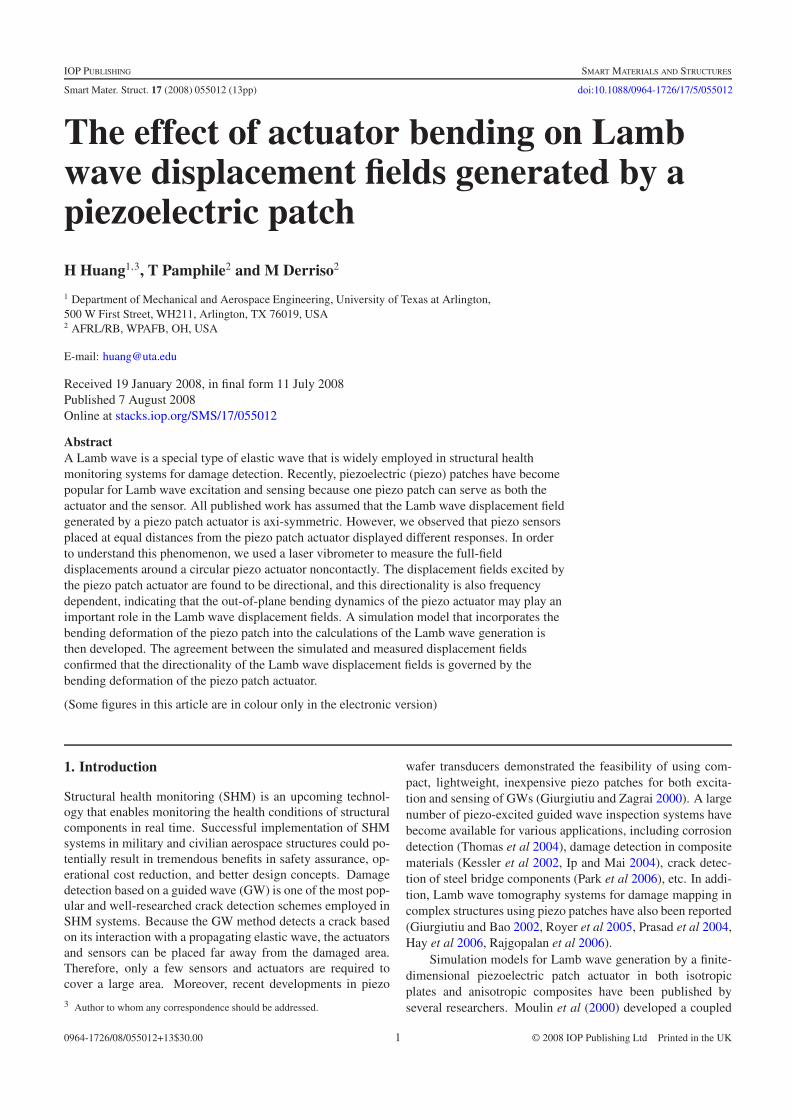
Figure 2. Piezo patch arrangement.
The solutions of (1) can be assumed to have the followingform:
φ(x, z) = �(z) exp[i(kx − ωt)],ϕ(x, z) = (z) exp[i(kx − ωt)], (3)
where ω is the angular frequency and k is the wavenumber.Substituting (3) into (1) and solving for the differentialequations yields the following expressions for the amplitudefunctions:
�(z) = A sin(pz) + B cos(pz),
(z) = C sin(qz) + D cos(qz),(4)
where
p2 = ω2/C2L − k2 and q2 = ω2/C2
T − k2. (5)
Since the stress components of the plate can be calculatedfrom φ(x, z) and ϕ(x, z) as
σxz = μ
(2
∂2φ
∂x∂z− ∂2ϕ
∂x2+ ∂2ϕ
∂z2
)and
σzz = λ
(∂2φ
∂x2+ ∂2φ
∂z2
)+ 2μ
(∂2φ
∂z2− ∂2ϕ
∂x∂z
),
(6)
applying the traction-free boundary conditions, σxz (±d) = 0and σzz(±d) = 0, yields the well-known Rayleigh–Lambfrequency equations,
tan(qd)
tan(pd)= −
(q2 − k2
)2
4pqk2(7a)
for anti-symmetric modes, and
tan(qd)
tan(pd)= − 4pqk2
(q2 − k2
)2(7b)
for symmetric modes, where d is the half-thickness of the plate.The wavenumber k is therefore a solution of (7a) or (7b).Each wavenumber k corresponds to a Lamb wave mode thatcan propagate in the plate. At higher excitation frequencies,equation (7) can have multiple solutions, indicating thatmultiple modes can be excited in the plate. For SHM purposes,the lowest symmetric mode S0 and anti-symmetric mode A0are most commonly used.
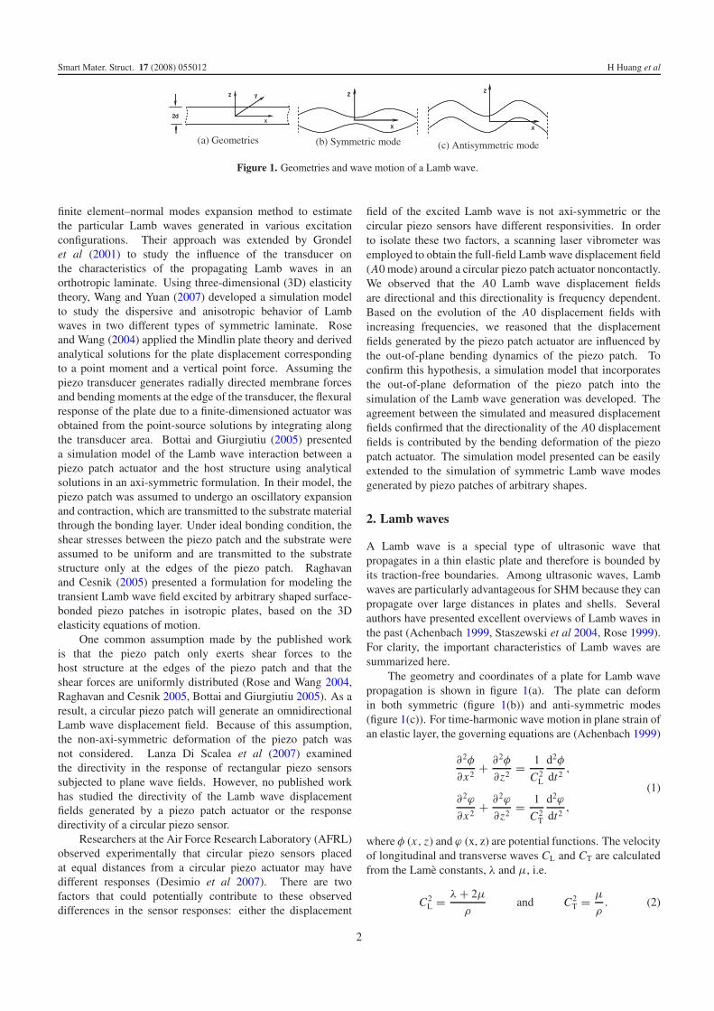
Figure 3. A0 amplitudes of piezo #5 measured by differentpiezo sensors.
3. Experiment observation
To investigate the observed variations in piezo sensorresponses, a large aluminum (Al) alloy panel (2024-T3, 0.78 min length, 0.76 m in width, and 1 mm in thickness) wasinstrumented with five piezo disks (APC 850-51D, 6.35 mmin diameter and 254 μm in thickness). The arrangement ofthe piezo disks is shown in figure 2. Regular strain gaugeepoxy (M-200 bond) was utilized to bond the piezo disks tothe Al alloy panel. Extra precautions were taken to ensure auniform bonding between the piezo disks and the Al panel,including roughening the surface with steel wires, cleaning thesurface using alcohol, applying the catalyst for the epoxy, andapplying even pressure to the piezo disks during epoxy curing.One of the piezo disks, piezo #5, was placed at the centerof the panel and was selected as the actuator. Four sensingpiezo disks were placed at 150 mm away from the actuator.For the excitation frequencies we are interested in, i.e. lessthan 250 kHz, the smallest Lamb wave wavelength λ is around1 mm. Therefore, the sensing piezos are placed in the far fieldof the piezo actuator (sensor/actuator distance L > D2/4/λ =1 mm, where D = 6.35 mm is the diameter of the actuatoraperture). Piezo #1 is mounted at the 9 o’clock direction(θ = 180◦) while the rest of piezo patches are mounted 90◦apart sequentially, following the clockwise direction.
3.1. Experiment measurements using piezo patch sensors
A 5.5-cycle Hanning-windowed tone-burst signal with a peak-to-peak amplitude of 9.658 V and an adjustable centerfrequency, generated by a signal generator (Agilent 33250A),was supplied to piezo #5 for Lamb wave generation. A custom-developed Labview program was used to automatically adjustthe excitation frequency and to record the outputs of the piezosensors from a data acquisition system. Triggered by theexcitation signal, the acquired data were averaged over tenexcitations. Subsequently, a MATLAB program was applied toseparate the A0 and S0 wavepackets using time gating and todetermine their peak amplitudes (Huang and Pamphile 2008).As shown in figure 3, the two piezo sensors, piezos #2 and#4, obtained different A0 amplitudes for most of the excitationfrequencies.
3
Smart Mater. Struct. 17 (2008) 055012 H Huang et al
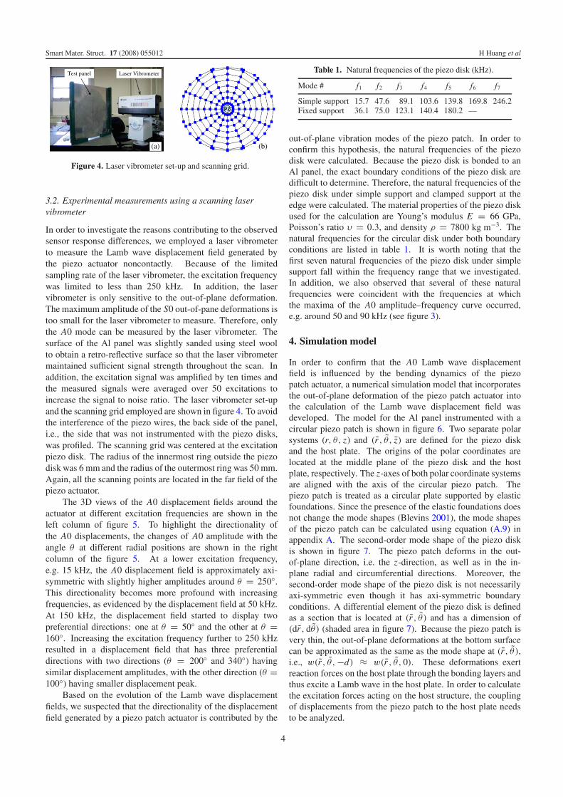
Figure 4. Laser vibrometer set-up and scanning grid.
3.2. Experimental measurements using a scanning laservibrometer
In order to investigate the reasons contributing to the observedsensor response differences, we employed a laser vibrometerto measure the Lamb wave displacement field generated bythe piezo actuator noncontactly. Because of the limitedsampling rate of the laser vibrometer, the excitation frequencywas limited to less than 250 kHz. In addition, the laservibrometer is only sensitive to the out-of-plane deformation.The maximum amplitude of the S0 out-of-pane deformations istoo small for the laser vibrometer to measure. Therefore, onlythe A0 mode can be measured by the laser vibrometer. Thesurface of the Al panel was slightly sanded using steel woolto obtain a retro-reflective surface so that the laser vibrometermaintained sufficient signal strength throughout the scan. Inaddition, the excitation signal was amplified by ten times andthe measured signals were averaged over 50 excitations toincrease the signal to noise ratio. The laser vibrometer set-upand the scanning grid employed are shown in figure 4. To avoidthe interference of the piezo wires, the back side of the panel,i.e., the side that was not instrumented with the piezo disks,was profiled. The scanning grid was centered at the excitationpiezo disk. The radius of the innermost ring outside the piezodisk was 6 mm and the radius of the outermost ring was 50 mm.Again, all the scanning points are located in the far field of thepiezo actuator.
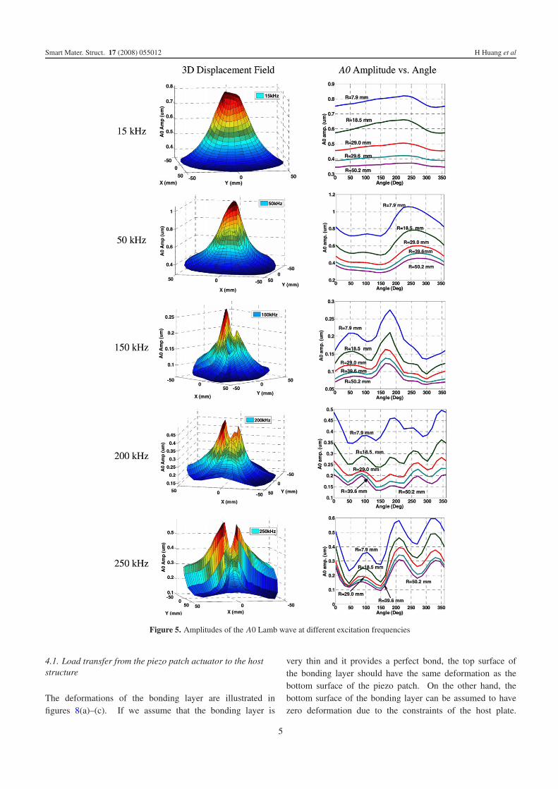
The 3D views of the A0 displacement fields around theactuator at different excitation frequencies are shown in theleft column of figure 5. To highlight the directionality ofthe A0 displacements, the changes of A0 amplitude with theangle θ at different radial positions are shown in the rightcolumn of the figure 5. At a lower excitation frequency,e.g. 15 kHz, the A0 displacement field is approximately axi-symmetric with slightly higher amplitudes around θ = 250◦.This directionality becomes more profound with increasingfrequencies, as evidenced by the displacement field at 50 kHz.At 150 kHz, the displacement field started to display twopreferential directions: one at θ = 50◦ and the other at θ =160◦. Increasing the excitation frequency further to 250 kHzresulted in a displacement field that has three preferentialdirections with two directions (θ = 200◦ and 340◦) havingsimilar displacement amplitudes, with the other direction (θ =100◦) having smaller displacement peak.
Based on the evolution of the Lamb wave displacementfields, we suspected that the directionality of the displacementfield generated by a piezo patch actuator is contributed by the
Table 1. Natural frequencies of the piezo disk (kHz).
Mode # f1 f2 f3 f4 f5 f6 f7
Simple support 15.7 47.6 89.1 103.6 139.8 169.8 246.2Fixed support 36.1 75.0 123.1 140.4 180.2 —
out-of-plane vibration modes of the piezo patch. In order toconfirm this hypothesis, the natural frequencies of the piezodisk were calculated. Because the piezo disk is bonded to anAl panel, the exact boundary conditions of the piezo disk aredifficult to determine. Therefore, the natural frequencies of thepiezo disk under simple support and clamped support at theedge were calculated. The material properties of the piezo diskused for the calculation are Young’s modulus E = 66 GPa,Poisson’s ratio υ = 0.3, and density ρ = 7800 kg m−3. Thenatural frequencies for the circular disk under both boundaryconditions are listed in table 1. It is worth noting that thefirst seven natural frequencies of the piezo disk under simplesupport fall within the frequency range that we investigated.In addition, we also observed that several of these naturalfrequencies were coincident with the frequencies at whichthe maxima of the A0 amplitude–frequency curve occurred,e.g. around 50 and 90 kHz (see figure 3).
4. Simulation model
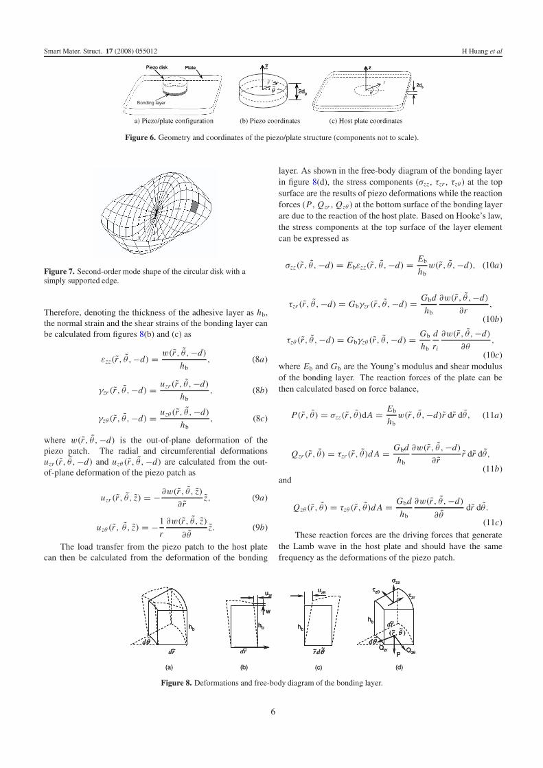
In order to confirm that the A0 Lamb wave displacementfield is influenced by the bending dynamics of the piezopatch actuator, a numerical simulation model that incorporatesthe out-of-plane deformation of the piezo patch actuator intothe calculation of the Lamb wave displacement field wasdeveloped. The model for the Al panel instrumented with acircular piezo patch is shown in figure 6. Two separate polarsystems (r, θ, z) and (r , θ , z) are defined for the piezo diskand the host plate. The origins of the polar coordinates arelocated at the middle plane of the piezo disk and the hostplate, respectively. The z-axes of both polar coordinate systemsare aligned with the axis of the circular piezo patch. Thepiezo patch is treated as a circular plate supported by elasticfoundations. Since the presence of the elastic foundations doesnot change the mode shapes (Blevins 2001), the mode shapesof the piezo patch can be calculated using equation (A.9) inappendix A. The second-order mode shape of the piezo diskis shown in figure 7. The piezo patch deforms in the out-of-plane direction, i.e. the z-direction, as well as in the in-plane radial and circumferential directions. Moreover, thesecond-order mode shape of the piezo disk is not necessarilyaxi-symmetric even though it has axi-symmetric boundaryconditions. A differential element of the piezo disk is definedas a section that is located at (r , θ ) and has a dimension of(dr , dθ ) (shaded area in figure 7). Because the piezo patch isvery thin, the out-of-plane deformations at the bottom surfacecan be approximated as the same as the mode shape at (r, θ ),i.e., w(r , θ ,−d) ≈ w(r , θ , 0). These deformations exertreaction forces on the host plate through the bonding layers andthus excite a Lamb wave in the host plate. In order to calculatethe excitation forces acting on the host structure, the couplingof displacements from the piezo patch to the host plate needsto be analyzed.
4
Smart Mater. Struct. 17 (2008) 055012 H Huang et al
Figure 5. Amplitudes of the A0 Lamb wave at different excitation frequencies
4.1. Load transfer from the piezo patch actuator to the hoststructure
The deformations of the bonding layer are illustrated infigures 8(a)–(c). If we assume that the bonding layer is
very thin and it provides a perfect bond, the top surface ofthe bonding layer should have the same deformation as thebottom surface of the piezo patch. On the other hand, thebottom surface of the bonding layer can be assumed to havezero deformation due to the constraints of the host plate.
5
Smart Mater. Struct. 17 (2008) 055012 H Huang et al
Figure 6. Geometry and coordinates of the piezo/plate structure (components not to scale).
Figure 7. Second-order mode shape of the circular disk with asimply supported edge.
Therefore, denoting the thickness of the adhesive layer as hb,the normal strain and the shear strains of the bonding layer canbe calculated from figures 8(b) and (c) as
εzz(r , θ ,−d) = w(r , θ ,−d)
hb, (8a)
γzr (r , θ ,−d) = uzr (r , θ ,−d)
hb, (8b)
γzθ (r , θ ,−d) = uzθ (r , θ ,−d)
hb, (8c)
where w(r , θ ,−d) is the out-of-plane deformation of thepiezo patch. The radial and circumferential deformationsuzr (r, θ ,−d) and uzθ (r , θ ,−d) are calculated from the out-of-plane deformation of the piezo patch as
uzr (r , θ , z) = −∂w(r , θ , z)
∂ rz, (9a)
uzθ (r , θ , z) = −1
r
∂w(r , θ , z)
∂θz. (9b)
The load transfer from the piezo patch to the host platecan then be calculated from the deformation of the bonding
layer. As shown in the free-body diagram of the bonding layerin figure 8(d), the stress components (σzz , τzr , τzθ ) at the topsurface are the results of piezo deformations while the reactionforces (P , Qzr , Qzθ ) at the bottom surface of the bonding layerare due to the reaction of the host plate. Based on Hooke’s law,the stress components at the top surface of the layer elementcan be expressed as
σzz(r , θ ,−d) = Ebεzz(r , θ ,−d) = Eb
hbw(r , θ ,−d), (10a)
τzr (r, θ ,−d) = Gbγzr (r, θ ,−d) = Gbd
hb
∂w(r , θ ,−d)
∂r,
(10b)
τzθ (r, θ ,−d) = Gbγzθ (r , θ ,−d) = Gb
hb
d
ri
∂w(r , θ ,−d)
∂θ,
(10c)where Eb and Gb are the Young’s modulus and shear modulusof the bonding layer. The reaction forces of the plate can bethen calculated based on force balance,
P(r , θ ) = σzz(r , θ )dA = Eb
hbw(r , θ ,−d)r dr dθ , (11a)
Qzr (r , θ ) = τzr (r , θ )d A = Gbd
hb
∂w(r , θ ,−d)
∂ rr dr dθ ,
(11b)and
Qzθ (r , θ ) = τzθ (r , θ )d A = Gbd
hb
∂w(r , θ ,−d)
∂θdr dθ .
(11c)
These reaction forces are the driving forces that generatethe Lamb wave in the host plate and should have the samefrequency as the deformations of the piezo patch.
Figure 8. Deformations and free-body diagram of the bonding layer.
6
Smart Mater. Struct. 17 (2008) 055012 H Huang et al
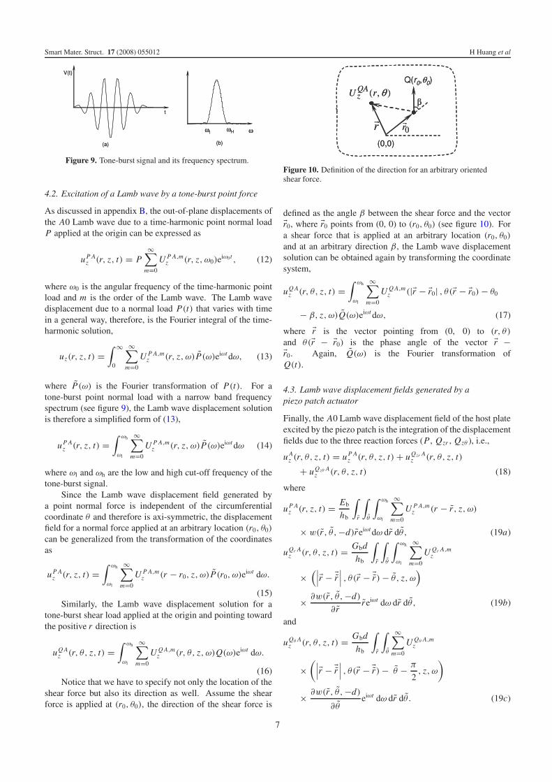
Figure 9. Tone-burst signal and its frequency spectrum.
4.2. Excitation of a Lamb wave by a tone-burst point force
As discussed in appendix B, the out-of-plane displacements ofthe A0 Lamb wave due to a time-harmonic point normal loadP applied at the origin can be expressed as
u P Az (r, z, t) = P
∞∑m=0
U P A,mz (r, z, ω0)e
iω0t , (12)
where ω0 is the angular frequency of the time-harmonic pointload and m is the order of the Lamb wave. The Lamb wavedisplacement due to a normal load P(t) that varies with timein a general way, therefore, is the Fourier integral of the time-harmonic solution,
uz(r, z, t) =∫ ∞
0
∞∑m=0
U P A,mz (r, z, ω)P(ω)eiωt dω, (13)
where P(ω) is the Fourier transformation of P(t). For atone-burst point normal load with a narrow band frequencyspectrum (see figure 9), the Lamb wave displacement solutionis therefore a simplified form of (13),
u P Az (r, z, t) =
∫ ωh
ωl
∞∑m=0
U P A,mz (r, z, ω)P(ω)eiωt dω (14)
where ωl and ωh are the low and high cut-off frequency of thetone-burst signal.
Since the Lamb wave displacement field generated bya point normal force is independent of the circumferentialcoordinate θ and therefore is axi-symmetric, the displacementfield for a normal force applied at an arbitrary location (r0, θ0)
can be generalized from the transformation of the coordinatesas
u P Az (r, z, t) =
∫ ωh
ωl
∞∑m=0
U P A,mz (r − r0, z, ω) P(r0, ω)eiωt dω.
(15)Similarly, the Lamb wave displacement solution for a
tone-burst shear load applied at the origin and pointing towardthe positive r direction is
uQ Az (r, θ, z, t) =
∫ ωh
ωl
∞∑m=0
U Q A,mz (r, θ, z, ω)Q(ω)eiωt dω.
(16)Notice that we have to specify not only the location of the
shear force but also its direction as well. Assume the shearforce is applied at (r0, θ0), the direction of the shear force is
Figure 10. Definition of the direction for an arbitrary orientedshear force.
defined as the angle β between the shear force and the vector�r0, where �r0 points from (0, 0) to (r0, θ0) (see figure 10). Fora shear force that is applied at an arbitrary location (r0, θ0)
and at an arbitrary direction β , the Lamb wave displacementsolution can be obtained again by transforming the coordinatesystem,
uQ Az (r, θ, z, t) =
∫ ωh
ωl
∞∑m=0
U Q A,mz (|�r − �r0| , θ(�r − �r0) − θ0
− β, z, ω)Q(ω)eiωt dω, (17)
where �r is the vector pointing from (0, 0) to (r, θ)
and θ(�r − �r0) is the phase angle of the vector �r −�r0. Again, Q(ω) is the Fourier transformation ofQ(t).
4.3. Lamb wave displacement fields generated by apiezo patch actuator
Finally, the A0 Lamb wave displacement field of the host plateexcited by the piezo patch is the integration of the displacementfields due to the three reaction forces (P , Qzr , Qzθ ), i.e.,
u Az (r, θ, z, t) = u P A
z (r, θ, z, t) + uQzr Az (r, θ, z, t)
+ uQzθ Az (r, θ, z, t) (18)
where
u P Az (r, z, t) = Eb
hb
∫r
∫θ
∫ ωh
ωl
∞∑m=0
U P A,mz (r − r , z, ω)
× w(r , θ ,−d)reiωt dω dr dθ , (19a)
uQr Az (r, θ, z, t) = Gbd
hb
∫r
∫θ
∫ ωh
ωl
∞∑m=0
U Qr A,mz
×(∣∣∣�r − �r
∣∣∣ , θ(�r − �r) − θ , z, ω)
× ∂w(r , θ ,−d)
∂ rreiωt dω dr dθ , (19b)
and
uQθ Az (r, θ, z, t) = Gbd
hb
∫r
∫θ
∞∑m=0
U Qθ A,mz
×(∣∣∣�r − �r
∣∣∣ , θ(�r − �r) − θ − π
2, z, ω
)
× ∂w(r , θ ,−d)
∂θeiωt dω dr dθ . (19c)
7
Smart Mater. Struct. 17 (2008) 055012 H Huang et al
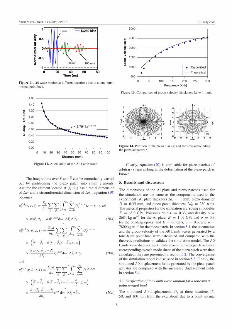
Figure 11. A0 wave motion at different locations due to a tone-burstnormal point load.
Figure 12. Attenuation of the A0 Lamb wave.
The integrations over r and θ can be numerically carriedout by partitioning the piezo patch into small elements.Assume the element located at (ri , θ j) has a radial dimensionof �ri and a circumferential dimension of �θ j , equation (19)becomes
u P Az (r, z, t) = Eb
hb
∑ri
∑θ j
[∫ ωh
ωl
∞∑m=0
U P A,mz (r − ri , z, ω)
× w(r , θ j ,−d)ri eiωt dω
]�ri�θ j , (20a)
uQr Az (r, θ, z, t) = Gbd
hb
∑ri
∑θ j
[∫ ωh
ωl
∞∑m=0
U Qr A,mz
×(∣∣∣�r − �r i
∣∣∣ , θ(�r − �r i ) − θ j , z, ω)
× ∂w(ri , θ j ,−d)
∂ riri e
iωt dω
]�ri�θ j , (20b)
and
uQθ Az (r, θ, z, t) = Gbd
hb
∑ri
∑θ j
[∫ ωh
ωl
∞∑m=0
U Qθ A,mz
×(∣∣∣�r − �r i
∣∣∣ , θ(�r − �r i ) − θ j − π
2, z, ω
)
× ∂w(ri , θ j ,−d)
∂θ j
eiωt dω
]�ri�θ j . (20c)
Figure 13. Comparison of group velocity (thickness 2d = 1 mm).
Figure 14. Partition of the piezo disk (a) and the area surroundingthe piezo actuator (b).
Clearly, equation (20) is applicable for piezo patches ofarbitrary shape as long as the deformation of the piezo patch isknown.
5. Results and discussion
The dimensions of the Al plate and piezo patches used forthe simulation are the same as the components used in theexperiment (Al plate thickness 2ds = 1 mm, piezo diameterD = 6.35 mm, and piezo patch thickness 2dp = 250 μm).The material properties for the simulation are Young’s modulusE = 68.9 GPa, Poisson’s ratio υ = 0.33, and density ρ =2684 kg m−3 for the Al plate, E = 1.09 GPa and υ = 0.3for the bonding epoxy, and E = 66 GPa, υ = 0.3, and ρ =7800 kg m−3 for the piezo patch. In section 5.1, the attenuationand the group velocity of the A0 Lamb waves generated by atone-burst point load were calculated and compared with thetheoretic predictions to validate the simulation model. The A0Lamb wave displacement fields around a piezo patch actuatorcorresponding to each mode shape of the piezo patch were thencalculated; they are presented in section 5.2. The convergenceof the simulation model is discussed in section 5.3. Finally, thesimulated A0 displacement fields generated by the piezo patchactuator are compared with the measured displacement fieldsin section 5.4.
5.1. Verification of the Lamb wave solution for a tone-burstpoint normal load
The simulated A0 displacements Uz at three locations (5,50, and 100 mm from the excitation) due to a point normal
8
Smart Mater. Struct. 17 (2008) 055012 H Huang et al
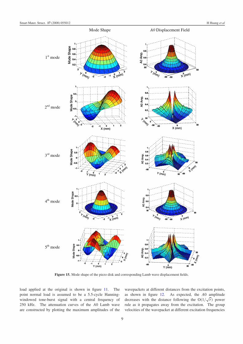
Figure 15. Mode shape of the piezo disk and corresponding Lamb wave displacement fields.
load applied at the original is shown in figure 11. Thepoint normal load is assumed to be a 5.5-cycle Hanning-windowed tone-burst signal with a central frequency of250 kHz. The attenuation curves of the A0 Lamb waveare constructed by plotting the maximum amplitudes of the
wavepackets at different distances from the excitation points,as shown in figure 12. As expected, the A0 amplitudedecreases with the distance following the O(1/
√r) power
rule as it propagates away from the excitation. The groupvelocities of the wavepacket at different excitation frequencies
9
Smart Mater. Struct. 17 (2008) 055012 H Huang et al
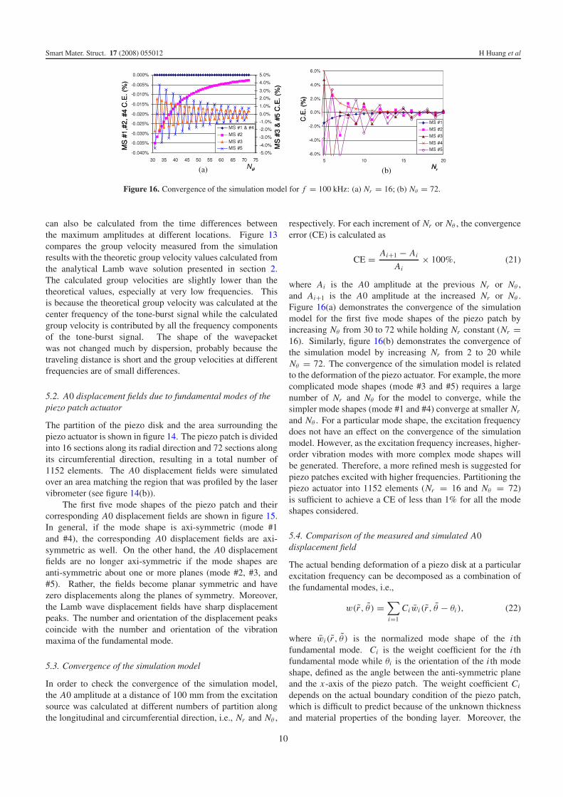
Figure 16. Convergence of the simulation model for f = 100 kHz: (a) Nr = 16; (b) Nθ = 72.
can also be calculated from the time differences betweenthe maximum amplitudes at different locations. Figure 13compares the group velocity measured from the simulationresults with the theoretic group velocity values calculated fromthe analytical Lamb wave solution presented in section 2.The calculated group velocities are slightly lower than thetheoretical values, especially at very low frequencies. Thisis because the theoretical group velocity was calculated at thecenter frequency of the tone-burst signal while the calculatedgroup velocity is contributed by all the frequency componentsof the tone-burst signal. The shape of the wavepacketwas not changed much by dispersion, probably because thetraveling distance is short and the group velocities at differentfrequencies are of small differences.
5.2. A0 displacement fields due to fundamental modes of thepiezo patch actuator
The partition of the piezo disk and the area surrounding thepiezo actuator is shown in figure 14. The piezo patch is dividedinto 16 sections along its radial direction and 72 sections alongits circumferential direction, resulting in a total number of1152 elements. The A0 displacement fields were simulatedover an area matching the region that was profiled by the laservibrometer (see figure 14(b)).
The first five mode shapes of the piezo patch and theircorresponding A0 displacement fields are shown in figure 15.In general, if the mode shape is axi-symmetric (mode #1and #4), the corresponding A0 displacement fields are axi-symmetric as well. On the other hand, the A0 displacementfields are no longer axi-symmetric if the mode shapes areanti-symmetric about one or more planes (mode #2, #3, and#5). Rather, the fields become planar symmetric and havezero displacements along the planes of symmetry. Moreover,the Lamb wave displacement fields have sharp displacementpeaks. The number and orientation of the displacement peakscoincide with the number and orientation of the vibrationmaxima of the fundamental mode.
5.3. Convergence of the simulation model
In order to check the convergence of the simulation model,the A0 amplitude at a distance of 100 mm from the excitationsource was calculated at different numbers of partition alongthe longitudinal and circumferential direction, i.e., Nr and Nθ ,
respectively. For each increment of Nr or Nθ , the convergenceerror (CE) is calculated as
CE = Ai+1 − Ai
Ai× 100%, (21)
where Ai is the A0 amplitude at the previous Nr or Nθ ,and Ai+1 is the A0 amplitude at the increased Nr or Nθ .Figure 16(a) demonstrates the convergence of the simulationmodel for the first five mode shapes of the piezo patch byincreasing Nθ from 30 to 72 while holding Nr constant (Nr =16). Similarly, figure 16(b) demonstrates the convergence ofthe simulation model by increasing Nr from 2 to 20 whileNθ = 72. The convergence of the simulation model is relatedto the deformation of the piezo actuator. For example, the morecomplicated mode shapes (mode #3 and #5) requires a largenumber of Nr and Nθ for the model to converge, while thesimpler mode shapes (mode #1 and #4) converge at smaller Nr
and Nθ . For a particular mode shape, the excitation frequencydoes not have an effect on the convergence of the simulationmodel. However, as the excitation frequency increases, higher-order vibration modes with more complex mode shapes willbe generated. Therefore, a more refined mesh is suggested forpiezo patches excited with higher frequencies. Partitioning thepiezo actuator into 1152 elements (Nr = 16 and Nθ = 72)is sufficient to achieve a CE of less than 1% for all the modeshapes considered.
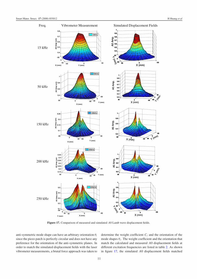
5.4. Comparison of the measured and simulated A0displacement field
The actual bending deformation of a piezo disk at a particularexcitation frequency can be decomposed as a combination ofthe fundamental modes, i.e.,
w(r , θ ) =∑i=1
Ci wi (r , θ − θi), (22)
where wi(r , θ ) is the normalized mode shape of the i thfundamental mode. Ci is the weight coefficient for the i thfundamental mode while θi is the orientation of the i th modeshape, defined as the angle between the anti-symmetric planeand the x-axis of the piezo patch. The weight coefficient Ci
depends on the actual boundary condition of the piezo patch,which is difficult to predict because of the unknown thicknessand material properties of the bonding layer. Moreover, the
10
Smart Mater. Struct. 17 (2008) 055012 H Huang et al
Figure 17. Comparison of measured and simulated A0 Lamb wave displacement fields.
anti-symmetric mode shape can have an arbitrary orientation θi
since the piezo patch is perfectly circular and does not have anypreference for the orientation of the anti-symmetric planes. Inorder to match the simulated displacement fields with the laservibrometer measurements, a brutal force approach was taken to
determine the weight coefficient Ci and the orientation of themode shapes θi . The weight coefficient and the orientation thatmatch the calculated and measured A0 displacement fields atdifferent excitation frequencies are listed in table 2. As shownin figure 17, the simulated A0 displacement fields matched
11
Smart Mater. Struct. 17 (2008) 055012 H Huang et al
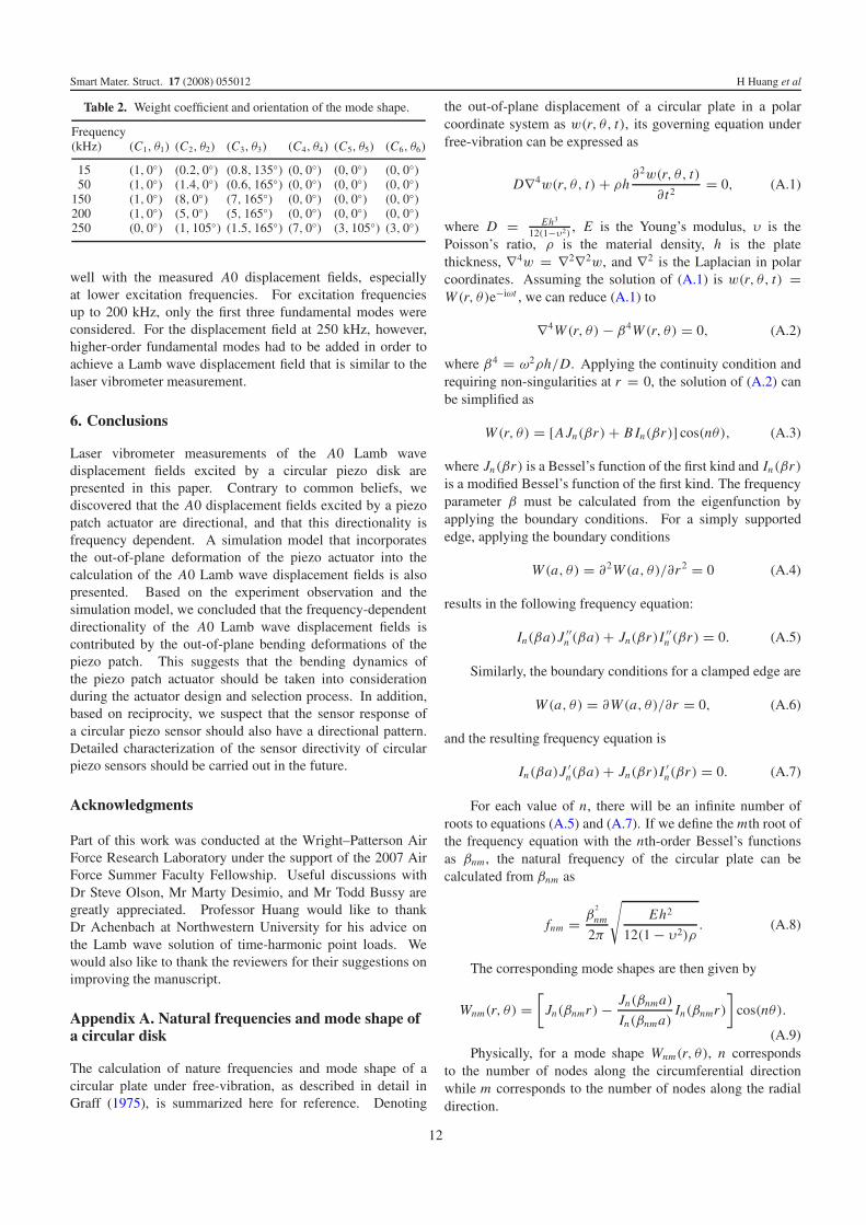
Table 2. Weight coefficient and orientation of the mode shape.
Frequency(kHz) (C1, θ1) (C2, θ2) (C3, θ3) (C4, θ4) (C5, θ5) (C6, θ6)
15 (1, 0◦) (0.2, 0◦) (0.8, 135◦) (0, 0◦) (0, 0◦) (0, 0◦)50 (1, 0◦) (1.4, 0◦) (0.6, 165◦) (0, 0◦) (0, 0◦) (0, 0◦)
150 (1, 0◦) (8, 0◦) (7, 165◦) (0, 0◦) (0, 0◦) (0, 0◦)200 (1, 0◦) (5, 0◦) (5, 165◦) (0, 0◦) (0, 0◦) (0, 0◦)250 (0, 0◦) (1, 105◦) (1.5, 165◦) (7, 0◦) (3, 105◦) (3, 0◦)
well with the measured A0 displacement fields, especiallyat lower excitation frequencies. For excitation frequenciesup to 200 kHz, only the first three fundamental modes wereconsidered. For the displacement field at 250 kHz, however,higher-order fundamental modes had to be added in order toachieve a Lamb wave displacement field that is similar to thelaser vibrometer measurement.
6. Conclusions
Laser vibrometer measurements of the A0 Lamb wavedisplacement fields excited by a circular piezo disk arepresented in this paper. Contrary to common beliefs, wediscovered that the A0 displacement fields excited by a piezopatch actuator are directional, and that this directionality isfrequency dependent. A simulation model that incorporatesthe out-of-plane deformation of the piezo actuator into thecalculation of the A0 Lamb wave displacement fields is alsopresented. Based on the experiment observation and thesimulation model, we concluded that the frequency-dependentdirectionality of the A0 Lamb wave displacement fields iscontributed by the out-of-plane bending deformations of thepiezo patch. This suggests that the bending dynamics ofthe piezo patch actuator should be taken into considerationduring the actuator design and selection process. In addition,based on reciprocity, we suspect that the sensor response ofa circular piezo sensor should also have a directional pattern.Detailed characterization of the sensor directivity of circularpiezo sensors should be carried out in the future.
Acknowledgments
Part of this work was conducted at the Wright–Patterson AirForce Research Laboratory under the support of the 2007 AirForce Summer Faculty Fellowship. Useful discussions withDr Steve Olson, Mr Marty Desimio, and Mr Todd Bussy aregreatly appreciated. Professor Huang would like to thankDr Achenbach at Northwestern University for his advice onthe Lamb wave solution of time-harmonic point loads. Wewould also like to thank the reviewers for their suggestions onimproving the manuscript.
Appendix A. Natural frequencies and mode shape ofa circular disk
The calculation of nature frequencies and mode shape of acircular plate under free-vibration, as described in detail inGraff (1975), is summarized here for reference. Denoting
the out-of-plane displacement of a circular plate in a polarcoordinate system as w(r, θ, t), its governing equation underfree-vibration can be expressed as
D∇4w(r, θ, t) + ρh∂2w(r, θ, t)
∂ t2= 0, (A.1)
where D = Eh3
12(1−υ2), E is the Young’s modulus, υ is the
Poisson’s ratio, ρ is the material density, h is the platethickness, ∇4w = ∇2∇2w, and ∇2 is the Laplacian in polarcoordinates. Assuming the solution of (A.1) is w(r, θ, t) =W (r, θ)e−iωt , we can reduce (A.1) to
∇4W (r, θ) − β4W (r, θ) = 0, (A.2)
where β4 = ω2ρh/D. Applying the continuity condition andrequiring non-singularities at r = 0, the solution of (A.2) canbe simplified as
W (r, θ) = [AJn(βr) + B In(βr)] cos(nθ), (A.3)
where Jn(βr) is a Bessel’s function of the first kind and In(βr)
is a modified Bessel’s function of the first kind. The frequencyparameter β must be calculated from the eigenfunction byapplying the boundary conditions. For a simply supportededge, applying the boundary conditions
W (a, θ) = ∂2W (a, θ)/∂r 2 = 0 (A.4)
results in the following frequency equation:
In(βa)J ′′n (βa) + Jn(βr)I ′′
n (βr) = 0. (A.5)
Similarly, the boundary conditions for a clamped edge are
W (a, θ) = ∂W (a, θ)/∂r = 0, (A.6)
and the resulting frequency equation is
In(βa)J ′n(βa) + Jn(βr)I ′
n(βr) = 0. (A.7)
For each value of n, there will be an infinite number ofroots to equations (A.5) and (A.7). If we define the mth root ofthe frequency equation with the nth-order Bessel’s functionsas βnm , the natural frequency of the circular plate can becalculated from βnm as
fnm = β2
nm
2π
√Eh2
12(1 − υ2)ρ. (A.8)
The corresponding mode shapes are then given by
Wnm(r, θ) =[
Jn(βnmr) − Jn(βnma)
In(βnma)In(βnmr)
]cos(nθ).
(A.9)Physically, for a mode shape Wnm(r, θ), n corresponds
to the number of nodes along the circumferential directionwhile m corresponds to the number of nodes along the radialdirection.
12
Smart Mater. Struct. 17 (2008) 055012 H Huang et al
Appendix B. Lamb wave displacement fieldgenerated by a time-harmonic point load
The Lamb wave displacement field in a thin plate generatedby a time-harmonic point load, derived by Achenbach(2003) using elastodynamic reciprocity, is summarized inthis appendix. The displacement due to a point load ofarbitrary direction can be expressed as the superpositionof displacements due to the vertical component P and thehorizontal component Q:
u(r, θ, z) = u P(r, θ, z) + uQ(r, θ, z). (B.1)
Each of these solutions can obtained as the superpositionof a symmetric and an anti-symmetric solution:
u P (r, θ, z) = u P S(r, θ, z) + u P A(r, θ, z), (B.2)
uQ(r, θ, z) = uQS(r, θ, z) + uQ A(r, θ, z). (B.3)
For a time-harmonic horizontal point load Q, the out-of-plane anti-symmetric displacement is calculated from
uQ Az (r, θ, z) = Q
∞∑m=0
km
4i
V mA (z0)
I Amm
W mA (z)H (1)
1 (kmr) cos θ
= Q∞∑
m=0
U Q A,mz (r, θ, z), (B.4)
where
I Amm = μ
[cA
1 sin2(pd) + cA2 sin2(qd)
], (B.5)
cA1 = (k2
n − q2)(k2n + q2)
2q3k3n
[2qd(k2n − q2)
+ (k2n + 7q2) sin(2qd)], (B.6)
cA2 = k2
n + q2
pk3n
[4k2
n pd − 2(k2n − 2p2) sin(2pd)
], (B.7)
and
V mA (z) = a1 sin(pz) + a2 sin(qz) (B.8)
a1 = 2 sin(qd), a2 = −(k2m − q2)/k2
m sin(pd). (B.9)
The out-of-plane anti-symmetric displacement generatedby a time-harmonic vertical point load P is given as
u P Az (r, z) =
∞∑m=0
km
4i
W mA (z0)
I Amm
W mA (z)H (1)
0 (kmr)P
= P∞∑
m=0
U P A,mz (r, z), (B.10)
where
W mA (z) = a3 cos(pz) + a4 cos(qz), (B.11)
a3 = 2(p/km) sin(qd), a4 = 2(k2m−q2)/(qkm) sin(pd),
(B.12)and H (1)
υ is the Hankel function of the first kind. The solutionfor the symmetric modes is similar and can be found inAchenbach (2003).
References
Achenbach J D 1999 Waves Propagation in Elastic Solids(New York: North-Holland)
Achenbach J D 2003 Reciprocity in Elastodynamics(Cambridge: Cambridge University Press)
Blevins R 2001 Formulas for Natural Frequency and Mode Shape(New York: Van Norstrand Reinhold)
Bottai G and Giurgiutiu V 2005 Simulation of the Lamb waveinteraction between piezoelectric wafer active sensors and hoststructure Proc. SPIE 5765 259–70
Desimio M P, Olson S E, Montes de Oca J and Brown K S 2007SHM of cracks and corrosion in aerospace shell structure Struct.Health Monit. 1 281–7
Giurgiutiu V and Bao J 2002 Embedded-ultrasonics structural radarfor nondestructive evaluation of thin-wall structures ASMEAerosp. Div. Publ. AD 67 333–40
Giurgiutiu V and Zagrai A N 2000 Characterization of piezoelectricwafer active sensors J. Intell. Mater. Syst. Struct. 11 959–76
Graff K F 1975 Wave Motion in Elastic Solids (Columbus, OH: OhioState University Press)
Grondel S, Delebarre C and Assaad J 2001 Modeling of Lamb wavegeneration for application in health monitoring of compositeplates IEEE Ultrasonics Symp. pp 721–4
Hay T, Royar R, Gao H, Zhao X and Rose J 2006 A comparison ofembedded sensor Lamb wave ultrasonic tomography approachesfor material loss detection Smart Mater. Struct. 15 946–51
Huang H and Pamphile T 2008 Signal processing for Lamb wavesignals excited by piezoelectric patches SenSIP Workshop(Sedona Arizona)
Ip K and Mai Y 2004 Delamination detection in smart compositebeams using Lamb waves Smart Mater. Struct. 13 544–51
Kessler S, Spearing S M and Soutis C 2002 Damage detection incomposite materials using Lamb wave method Smart Mater.Struct. 11 269–78
Lanza Di Scalea F, Matt H and Bartoli I 2007 The response ofrectangular piezoelectric sensors to Rayleigh and Lambultrasonic waves J. Acoust. Soc. Am. 121 175–87
Moulin E, Assaad J and Delebarre C 2000 Modeling of Lamb wavesgenerated by integrated transducers in composite plates using acoupled finite element–normal modes expansion methodJ. Acoust. Soc. Am. 107 87–94
Park S, Yun C, Roh Y and Lee J 2006 PZT-based active damagedetection techniques for steel bridge components Smart Mater.Struct. 15 957–66
Prasad S M, Balasubramaniam K and Krisnamurthy C V 2004Structural health monitoring of composite structure using Lambwave tomography Smart Mater. Struct. 13 N73–9
Raghavan A and Cesnik C E S 2005 Finite-dimensional piezoelectrictransducer modeling for guided wave based structural healthmonitoring Smart Mater. Struct. 14 1448–61
Rajgopalan J, Balasubramaniam K and Krisnamurthy C V 2006 Aphase reconstruction algorithm for Lamb wave based structuralhealth monitoring of anisotropic multilayered composite platesJ. Acoust. Soc. Am. 119 872–8
Rose J L 1999 Ultrasonic Waves in Solid Media (Cambridge:Cambridge University Press)
Rose L R F and Wang C H 2004 Mindlin plate theory for damagedetection source solutions J. Acoust. Soc. Am. 116 154–71
Royer R Jr, Hay T, Owens S, Fina T, Gao H and Rose J 2005Corrosion detection in large complex aircraft components usingLamb wave tomography Int. SAMPE Tech. Conf. Soc.-37thISTC p 12
Staszewski W, Boller C and Tomlinson G 2004 Health Monitoring ofAerospace Structures: Smart Sensor Technologies and SignalProcessing (Chichester: Wiley)
Thomas D, Welter J and Giurgiutiu V 2004 Corrosion damagedetection with piezoelectric wafer active sensors Proc. SPIE5394 11
Wang L and Yuan F G 2007 Group velocity and characteristic wavecurves of Lamb waves in composites modeling and experimentsComput. Sci. Technol. 67 1270–84
13


![Piezoelectric Bimorph Actuator with Integrated Strain Sensing … · 2018-06-07 · gauges can be used as displacement sensors for controlling piezoelectric stack actuators [12]](https://img.pdfslide.us/doc/110x75/5e793c4c8085ef1b260e813c/piezoelectric-bimorph-actuator-with-integrated-strain-sensing-2018-06-07-gauges.jpg)