Embed Size (px)
Citation preview
Simulation of Piezoelectric Induced Lamb Waves in Plates
C. WILLBERG, J. M. VIVAR-PEREZ, Z. AHMAD and U. GABBERT
ABSTRACT
The use of Lamb waves for damage detection and non-destructive evaluation have been increased in the last decades. For this purposes, it is strictly necessary to understand the propagation phenomena in different structures, and the influence on the geometrical and mechanical properties of the system actuator-sensors-host structure. We find in numerical simulation and computer visualization important tools to clarify this dependence under certain circumstances. This work is a compilation of some work done in regards to numerical experiments related the behavior of piezoelectric induced Lamb waves in plates. Keywords: Structural Health Monitoring (SHM), Lamb Waves, FEM, SEM. INTRODUCTION
The application of elastic guided waves to inspect structures has a long history, and its application for an online monitoring of structures is quite common nowadays. In thin-walled structures, special elastic guided waves between free stress constrained parallel boundaries occur, named after Horace Lamb in 1917 [1]. Among the advantages of Lamb wave based methods against other forms of online monitoring applications, is the relatively long range of propagation of these waves due to their relatively low rate of attenuation in comparison to other classes of ultrasonic waves. The consequence is the reduction of the number of sensors per interrogated area in the applications. The properties of Lamb waves are well discussed in the book by Victorov [2].
The recent increasing improvement on the quality of piezoelectric transducers allows the use of these materials in an easy way for exciting and sensing Lamb waves. The goal of the paper is to successfully model numerically the behavior of Lamb waves induced by piezoelectric materials and their interaction with the non healthy structure.Results are presented in the first section of the paper. Some details on the behavior of lamb waves in isotropic plates are given and their interaction with damages using a relatively simple model to study the phenomena of mode conversion.
For real applications it is necessary to understand the mechanical behavior of the coupled actuator/structure, sensor/structure system. Frequently, the electrical connection to the piezoceramic and also the coupling between the latter and the structure are assumed to be ideal and without irregularities. As consequence, the deformation over the active surface of the piezoelectric transducer in the plate is modeled as homogeneously distributed and the induced guided wave does not show a preference direction where the signal amplitude is higher. Nevertheless, Huang et al [3] showed that, in practice, circular shaped actuator can introduce a non homogeneous angle dependence on amplitude distribution in the wave front in an isotropic material and this distribution is frequency dependent. Otto-von-Guericke-University, Institute of Mechanics, Universitätsplatz 2, building 10, 39106 Magdeburg, Germany.
On this contribution, we will show that the effect of considering some
irregularities out off the standard axisymmetrical distributions of loads in the
actuator. Under these conditions, the energy distribution of amplitudes on the wave
front is shown to be directional. This directionality is frequency dependent and is
intrinsically related to the bending modes of the piezoceramic disc used as actuator.
This is the topic treated on the second section. The mentioned irregularity, on our
case, is taken as the welding point between the wire and the piezoelectric disc. The
welding area is neither uniformly nor axisymmetrically distributed on the upper
surface of the piezoactuator. Then, the deformations of the actuator under
homogeneous electric field are not axially symmetric any more, giving place to the
previously mentioned effect.
At the end of the contribution some analysis is done about the suitability of the
use of spectral methods to simulate the wave propagation phenomenon with the aim
to reduce computer memory storage and time of calculation for the mathematical
simulations. In the last section some elements of the theory behind spectral element
method is given and some comparisons to the classical finite element formulation in
simple models.
LAMB WAVES IN PLATES AND DAMAGES
Lamb waves in plates take place in more than one mode of two kinds called
symmetric (S) and anti-symmetric (A) modes. One important feature of Lamb
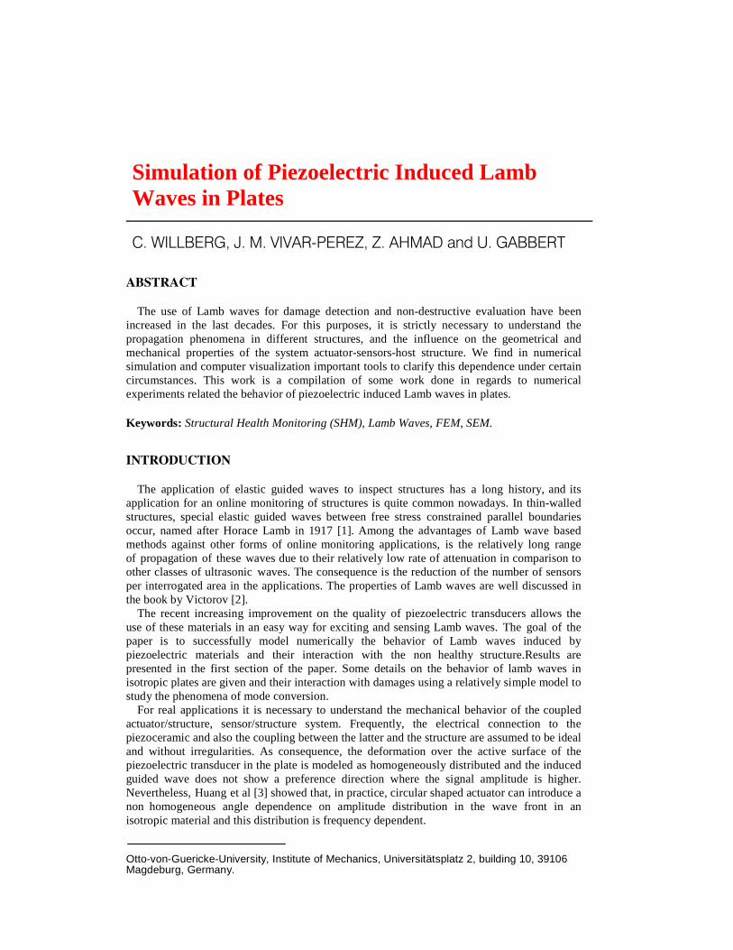
waves is their highly dispersive behavior. This behavior can be observed from the
Lamb wave’s dispersion curves which are the graphical representation of the phase
and the group velocities of each mode as shown for the case of an Aluminum plate
in figure 1. Once the curves are known, a compromise between shorter wave length,
less number of modes and less dispersion can be made to improve sensibility and
simplicity on the signals received on the sensors.
Figure 1. Group and phase velocity dispersion curves calculated by using analytical
formulas (asymmetric mode – dotted curve; symmetric mode – blue curve); 0A and 0S are
the left two curves
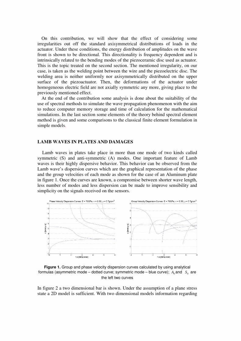
In figure 2 a two dimensional bar is shown. Under the assumption of a plane stress
state a 2D model is sufficient. With two dimensional models information regarding
mode conversion and reflection can be evaluated with less computational effort
than with comparable 3D models. By using further a pair of two coupled
piezoelectric patches as actuators on top and bottom of the plate it is possible to
send a nearly pure symmetric or a pure anti-symmetric wave with respect to the
plate mid plane. By using a further pair of two piezoelectric sensors it is possible to
interpret the different modes [7]. A Lamb wave is sent through this bar and interacts
with some different discontinuities as it travels. A “Hanning” window pulse with
central frequency 145 kHz is used. From figure 1, only the A0 and S0 modes occur
and have to be taken into account simplifying the research about mode conversion.
Figure 2. Two dimensional bar model to simulate the influence of different discontinuities to
the mode conversion of Lamb waves
Two examples from several numerically investigated experiments are presented in
relation to each other. Both of them show the changes of the sensor received signals
by a localized change of thickness (variant 1 and 2 in figure 2). The first numerical
example investigates the influence of a height change (0.6mm) at one side of a bar
only (see thickness change 1 in figure 2). In the second numerical experiment a
symmetric change of the thickness (2 times of 0.6mm) is investigated (see thickness
change 2 in figure 2). The differences of the measured response at the sensors
between the anti-symmetric and the symmetric change of thickness are discussed in
the following.
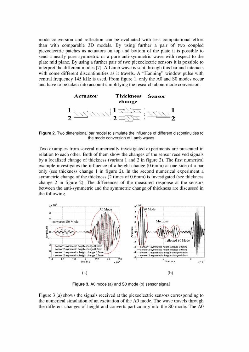
(a) (b)
Figure 3. A0 mode (a) and S0 mode (b) sensor signal
Figure 3 (a) shows the signals received at the piezoelectric sensors corresponding to
the numerical simulation of an excitation of the A0 mode. The wave travels through
the different changes of height and converts particularly into the S0 mode. The A0
mode is relatively dispersive in the chosen frequency
an evident shift of phase on the received signal due to the increase of the phase
velocity while traveling through the thickness change. This can be observed in the
differences between the results corresponding to two different thickness changes of
type 1 and type 2 (see f
respectively. In figure 3 (a)
to the transmitted S0 mode is shown, which is the result of a mode conversion after
the A0 mode has traveled through the thickness change. The dispersion effect of the
A0 mode in the signal of th
The S0 mode of the chosen numerical example shows a different behavior. In
contrast to the one site height change
for a symmetric change of thickness
of the thickness jump have influence on the amplitude maxima. Inside the mi
of Figure 3 (b) it can be seen, that the signal of the reference calculation has been
converted partially into an A0 mode. The symmetric change of t
mode conversion. Only partially reflections of the incoming signal can be seen in
the received signal. The amplitudes
reflected S0 mode in the mix zone
bonded to one side of the plate only, it is not possible to see any difference. The
investigated modes are not very sensitive against a symmetric thickness change.
Only the reflections of the traveling wave can be a sign for damage.
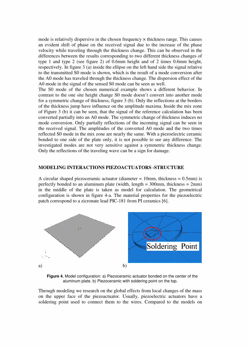
MODELING INTERACTIONS PIEZOACTUATORS
A circular shaped piezoceramic
perfectly bonded to an aluminum plate
in the middle of the plate
configuration is shown in
patch correspond to a zicronate lead PIC
a)
Figure 4. Model configuration: a) Piezoceramic actuator bonded on the center of the
aluminum plate. b)
Through modeling we research on
on the upper face of the piezoactuator
soldering point used to
is relatively dispersive in the chosen frequency × thickness range. This causes
an evident shift of phase on the received signal due to the increase of the phase
velocity while traveling through the thickness change. This can be observed in the
ences between the results corresponding to two different thickness changes of
figure 2) of 0.6mm height and of 2 times 0.6mm height,
(a) inside the ellipse on the left hand side the signal relative
to the transmitted S0 mode is shown, which is the result of a mode conversion after
the A0 mode has traveled through the thickness change. The dispersion effect of the
A0 mode in the signal of the sensed S0 mode can be seen as well.
The S0 mode of the chosen numerical example shows a different behavior. In
contrast to the one site height change S0 mode doesn’t convert into another mode
for a symmetric change of thickness, figure 3 (b). Only the reflections at the borders
of the thickness jump have influence on the amplitude maxima. Inside the mi
it can be seen, that the signal of the reference calculation has been
converted partially into an A0 mode. The symmetric change of thickness induces no
mode conversion. Only partially reflections of the incoming signal can be seen in
the received signal. The amplitudes of the converted A0 mode and the two times
reflected S0 mode in the mix zone are nearly the same. With a piezoelectric
e of the plate only, it is not possible to see any difference. The
investigated modes are not very sensitive against a symmetric thickness change.
Only the reflections of the traveling wave can be a sign for damage.
NG INTERACTIONS PIEZOACTUATORS -STRUCTURE
ceramic actuator (diameter = 10mm, thickness = 0.5mm)
nded to an aluminum plate (width, length = 300mm, thickness = 2mm)
in the middle of the plate is taken as model for calculation. The geometrical
shown in figure 4-a. The material properties for the piezoelectric
patch correspond to a zicronate lead PIC-181 from PI ceramics [6].
b)
Model configuration: a) Piezoceramic actuator bonded on the center of the
aluminum plate. b) Piezoceramic with soldering point on the top.
Through modeling we research on the global effects from local changes of the mass
on the upper face of the piezoactuator. Usually, piezoelectric actuators have a
used to connect them to the wires. Compared to the models on
thickness range. This causes
an evident shift of phase on the received signal due to the increase of the phase
velocity while traveling through the thickness change. This can be observed in the
ences between the results corresponding to two different thickness changes of
igure 2) of 0.6mm height and of 2 times 0.6mm height,
inside the ellipse on the left hand side the signal relative
to the transmitted S0 mode is shown, which is the result of a mode conversion after
the A0 mode has traveled through the thickness change. The dispersion effect of the
The S0 mode of the chosen numerical example shows a different behavior. In
ode doesn’t convert into another mode
eflections at the borders
of the thickness jump have influence on the amplitude maxima. Inside the mix zone
it can be seen, that the signal of the reference calculation has been
hickness induces no
mode conversion. Only partially reflections of the incoming signal can be seen in
of the converted A0 mode and the two times
ith a piezoelectric ceramic
e of the plate only, it is not possible to see any difference. The
investigated modes are not very sensitive against a symmetric thickness change.
STRUCTURE
0mm, thickness = 0.5mm) is
(width, length = 300mm, thickness = 2mm)
The geometrical
. The material properties for the piezoelectric
Model configuration: a) Piezoceramic actuator bonded on the center of the
Piezoceramic with soldering point on the top.
the global effects from local changes of the mass
piezoelectric actuators have a
Compared to the models on
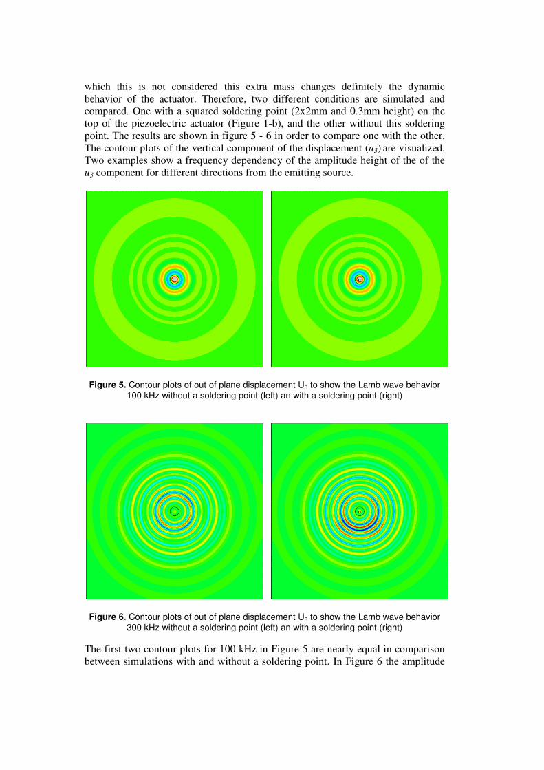
which this is not considered this extra mass changes definitely the dynamic
behavior of the actuator. Therefore, two different conditions are simulated and
compared. One with a squared soldering point (2x2mm and 0.3mm height) on the
top of the piezoelectric actuator (Figure 1-b), and the other without this soldering
point. The results are shown in figure 5 - 6 in order to compare one with the other.
The contour plots of the vertical component of the displacement (u3) are visualized.
Two examples show a frequency dependency of the amplitude height of the of the
u3 component for different directions from the emitting source.
Figure 5. Contour plots of out of plane displacement U3 to show the Lamb wave behavior
100 kHz without a soldering point (left) an with a soldering point (right)
Figure 6. Contour plots of out of plane displacement U3 to show the Lamb wave behavior
300 kHz without a soldering point (left) an with a soldering point (right)
The first two contour plots for 100 kHz in Figure 5 are nearly equal in comparison
between simulations with and without a soldering point. In Figure 6 the amplitude
distributions of u3 are different in each case. The dynamical behavior of the actuator
changes on the case of extra load considered and its behavior is frequency
dependent.
SIMULATIONS USING SPECTRAL ANALYSIS
Spectral analysis was used in order to obtain better accuracy with the same level
of discretization [8]. The wave equation is considered in the way fLu = , where L
stands for a differential operator. According to our approach, the function of
displacements ),( txu is globally approximated or interpolated as,
∑=
=≈N
n
nnN xtatxutxu0
)()(),(),( φ . (1)
The functions )(xnφ are the first N members of an orthonormal function basis,
and the coefficients functions )(tan are selected in such a way that they minimize
the residual R in some sense,
),(),())(),...,(;( 0 txftxLutataxR NN −= . (2)
The result is a system of ordinary differential equations for the functions )(tan .
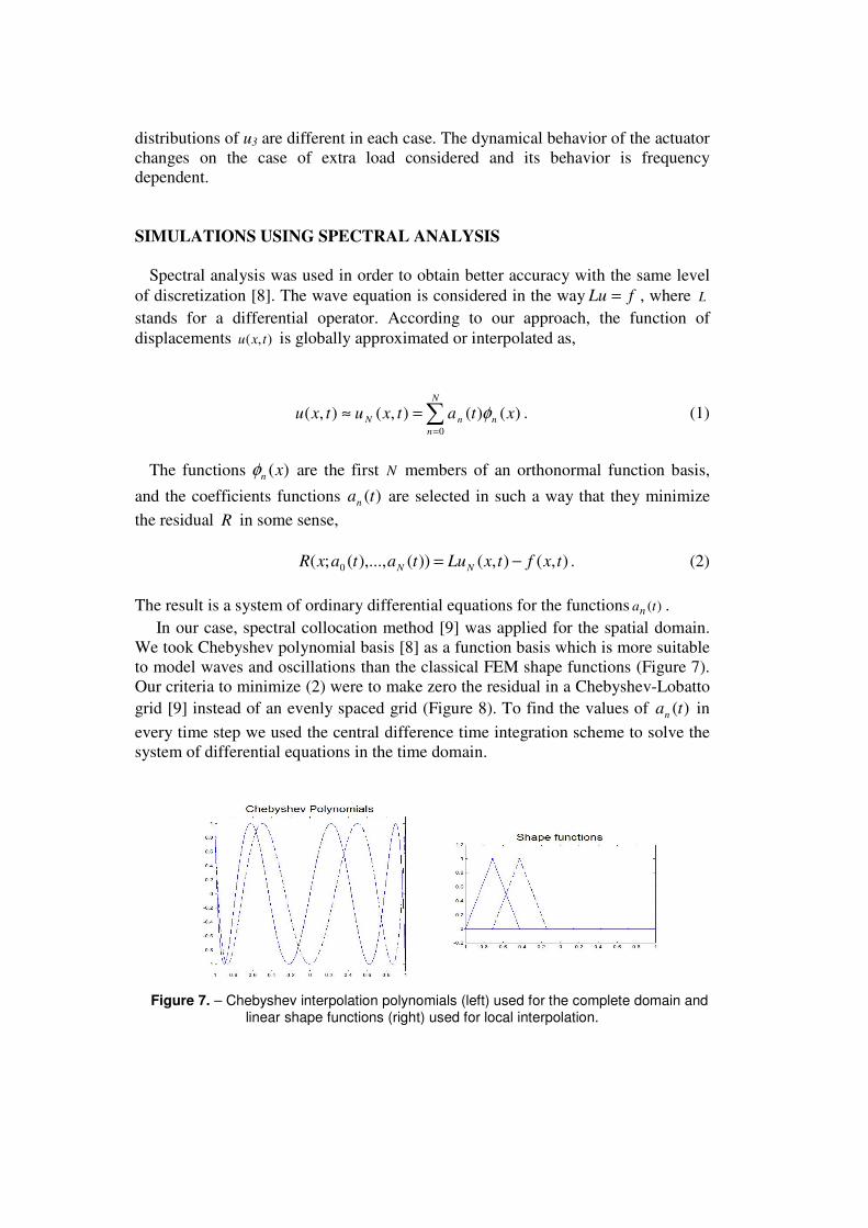
In our case, spectral collocation method [9] was applied for the spatial domain.
We took Chebyshev polynomial basis [8] as a function basis which is more suitable
to model waves and oscillations than the classical FEM shape functions (Figure 7).
Our criteria to minimize (2) were to make zero the residual in a Chebyshev-Lobatto
grid [9] instead of an evenly spaced grid (Figure 8). To find the values of )(tan in
every time step we used the central difference time integration scheme to solve the
system of differential equations in the time domain.
Figure 7. – Chebyshev interpolation polynomials (left) used for the complete domain and
linear shape functions (right) used for local interpolation.
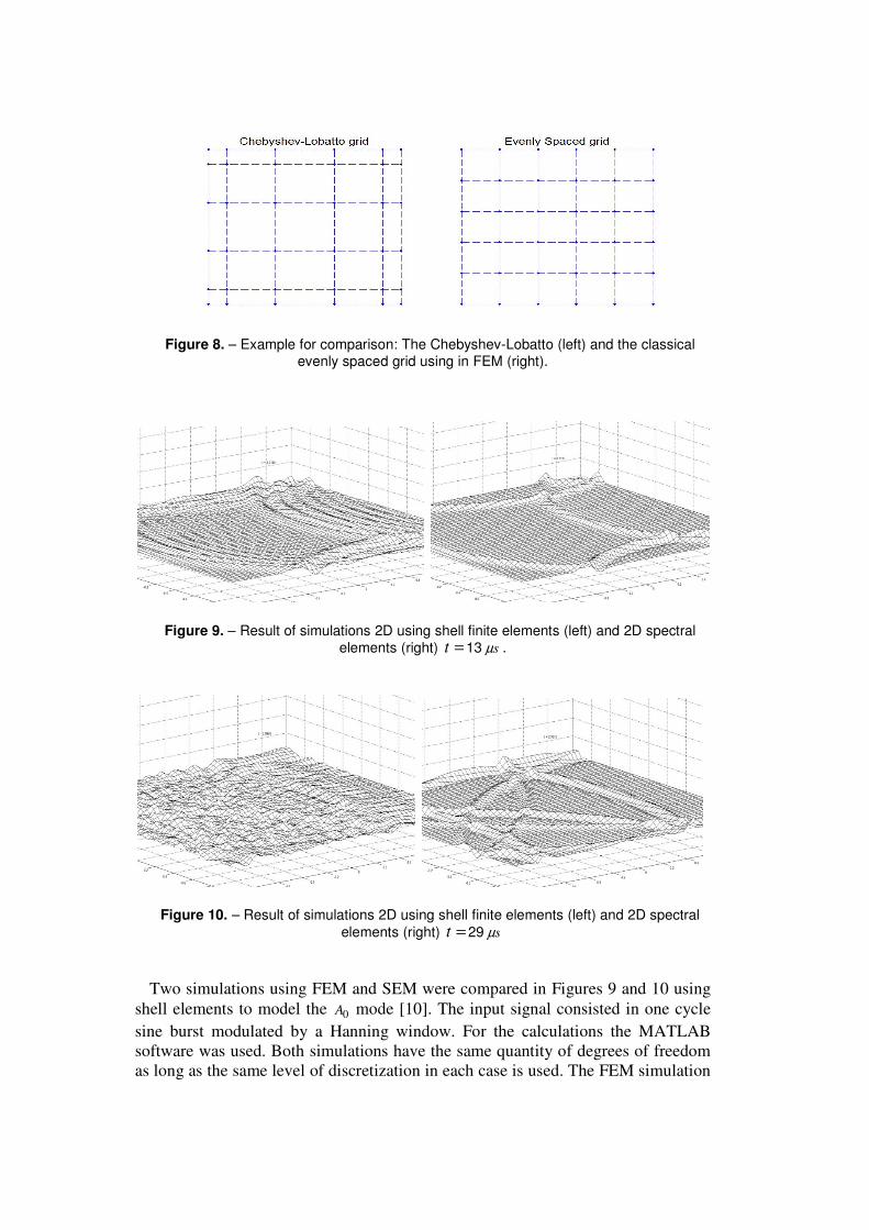
Figure 8. – Example for comparison: The Chebyshev-Lobatto (left) and the classical evenly spaced grid using in FEM (right).
Figure 9. – Result of simulations 2D using shell finite elements (left) and 2D spectral
elements (right) =t 13 sµ .
Figure 10. – Result of simulations 2D using shell finite elements (left) and 2D spectral
elements (right) =t 29 sµ
Two simulations using FEM and SEM were compared in Figures 9 and 10 using
shell elements to model the 0A mode [10]. The input signal consisted in one cycle
sine burst modulated by a Hanning window. For the calculations the MATLAB
software was used. Both simulations have the same quantity of degrees of freedom
as long as the same level of discretization in each case is used. The FEM simulation
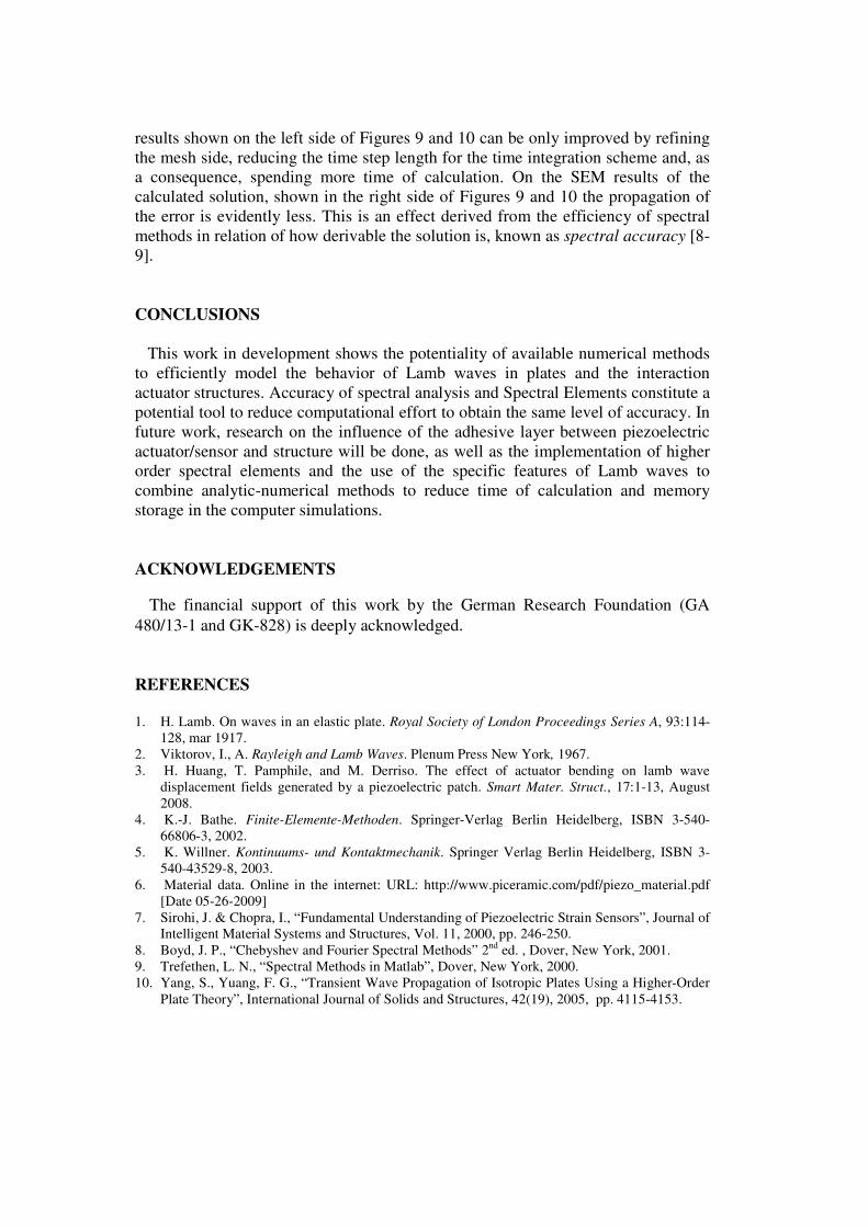
results shown on the left side of Figures 9 and 10 can be only improved by refining
the mesh side, reducing the time step length for the time integration scheme and, as
a consequence, spending more time of calculation. On the SEM results of the
calculated solution, shown in the right side of Figures 9 and 10 the propagation of
the error is evidently less. This is an effect derived from the efficiency of spectral
methods in relation of how derivable the solution is, known as spectral accuracy [8-
9].
CONCLUSIONS
This work in development shows the potentiality of available numerical methods
to efficiently model the behavior of Lamb waves in plates and the interaction
actuator structures. Accuracy of spectral analysis and Spectral Elements constitute a
potential tool to reduce computational effort to obtain the same level of accuracy. In
future work, research on the influence of the adhesive layer between piezoelectric
actuator/sensor and structure will be done, as well as the implementation of higher
order spectral elements and the use of the specific features of Lamb waves to
combine analytic-numerical methods to reduce time of calculation and memory
storage in the computer simulations.
ACKNOWLEDGEMENTS
The financial support of this work by the German Research Foundation (GA
480/13-1 and GK-828) is deeply acknowledged.
REFERENCES
1. H. Lamb. On waves in an elastic plate. Royal Society of London Proceedings Series A, 93:114-
128, mar 1917.
2. Viktorov, I., A. Rayleigh and Lamb Waves. Plenum Press New York, 1967.
3. H. Huang, T. Pamphile, and M. Derriso. The effect of actuator bending on lamb wave
displacement fields generated by a piezoelectric patch. Smart Mater. Struct., 17:1-13, August
2008.
4. K.-J. Bathe. Finite-Elemente-Methoden. Springer-Verlag Berlin Heidelberg, ISBN 3-540-
66806-3, 2002.
5. K. Willner. Kontinuums- und Kontaktmechanik. Springer Verlag Berlin Heidelberg, ISBN 3-
540-43529-8, 2003.
6. Material data. Online in the internet: URL: http://www.piceramic.com/pdf/piezo_material.pdf
[Date 05-26-2009]
7. Sirohi, J. & Chopra, I., “Fundamental Understanding of Piezoelectric Strain Sensors”, Journal of
Intelligent Material Systems and Structures, Vol. 11, 2000, pp. 246-250.
8. Boyd, J. P., “Chebyshev and Fourier Spectral Methods” 2nd
ed. , Dover, New York, 2001.
9. Trefethen, L. N., “Spectral Methods in Matlab”, Dover, New York, 2000.
10. Yang, S., Yuang, F. G., “Transient Wave Propagation of Isotropic Plates Using a Higher-Order
Plate Theory”, International Journal of Solids and Structures, 42(19), 2005, pp. 4115-4153.


![CORROSION DETECTION IN AERONAUTICAL STRUCTURES USING LAMB …€¦ · 10 [6,7]. Lamb waves are two groups of waves, the symmetric waves and the anti-symmetric waves, that satisfy](https://img.pdfslide.us/doc/110x75/5eac6ed92f470f78de1b8fc2/corrosion-detection-in-aeronautical-structures-using-lamb-10-67-lamb-waves-are.jpg)