Embed Size (px)
Citation preview


: ~ + e . , y , ~ . > s , ~ v ! , m,,, ... -ha??<< 9 ; ~ : ~ j t - ,%?L~:r,c:p?r< . . P.+,..-~:A . .. v p ~ t ;pi--,? - F : ~ ~ z . ~ CC
.. .~ . . C f -.:c.-.,r?l4. .,-.e.:..'",':+ ."I'"'( - - c c r r . p y I . , f5 * lT i,,. --= he-.?; -.,. ..I.c. i.,-- ..-:'ir:,-.r ..~ ., . ., . . . . . .. . . ,.,I . . . . . * , . - . ~. ,
+;,cr ..; -, ., . * .. , , ,,:,rq ,c,~?r ..-.. % .,.Lr - ?.?)-:,:
i . <. ~,.. ~~ :*",?,~.. .?-< 0:jr nb:>>.,r-:>-GC:, .. , 'r..;; P<-?~;?>,?< ;:.,;:.
,,I-"-" . "" :ijR?,,i.: 1?:7; y l , ; l - l . .-,--.'::1 ~. c. ?1.!*, . . rrlC-')II)-i !%inj: ' : . r :L r-l*:Ll,;- -+., t
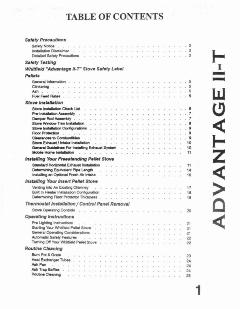
TABLE OF CONTENTS
Safety Precautions SafetyN otice . . . . . . . . . . . . . . . . . . . . . 3 lnstallathDiJdaimer . . . . . . . . . . . . . . . . . . . . . . 3 Detailed Safety Precautions . . . . . . . . . . . . . . . 3
Safety Testing Whitfield "Advantage 11-7 Stove Safety Label Pellets
. . . . . . . . . . . . . . . . . . . . . . . General lnfownakn 5 Clinkering . . . . . . . . . . . . . . . . . . . . . . . . . - 5 Ash . . . . . . . . . . . . . . . . . . . . . . . . . . . . 5 Fuel F d R a w . . . . . . . . . . . . . . . . . . . . . . . 5
Stow 1nst.lktion 57ovolruWktiarCh.dcList . . . . . . . . . . . . . . . . . 6 Pr,ln.tdl.tionAsmmbly . . . . . . . . . . . . . . . . 7 DvnplMAodAumbly . . . . . . . . . . . . . . . . . . 7
. . . . . . . . . . . . . . . . . . . S t o v e W n d o w T r i m l n ~ 8
. . . . . . . . . . . . . . . . . . . S h lnrwkfion ~ w . l i o n s 9 FkaFvdmxh . . . . . . . . . . . . . . . . . . . . . 9 Ckrvlarto CanbUrwI.. . . . . . . . . . . . . . . 9 SIowEduurt /Wolnsbktion . . . . . . . . . . . . . . . . . 10 ~ ~ F o r I n t t . l l i n g ~ S y l l r n . . . . . . . . . 10 M o b i k ~ l ~ . . . . . . . . . . . . . . . . . 11
Installing Y w r Fmrhndlng Palkt Stow StMdardtiotbWwExhurrti- . . . . . . . . . . . . . 11 Detwnining Equivaknt Pip. Lengih . . . . . . . . . . . . . . 14 InstallingmOptionalFreshAirlnbke . . . . . . . . . . . . . . . . 16
Installing Your Insert Pellet Stove Veoting Into An Existing Chimney . . . . . . . . . . . . . . 17 k i n In Ho8ter Installatian Configuration . . . . . . . . . . . . . . . 18 Wemining Fbor Protector T h i i s s . . . . . . . . . . . . . 18
7Bermostat Installetion / Control Panel Removal Stove Opaafing Contrds . . . . . . . . . . . . . . . . 20
Operating instructions R e Lighting Instructions . . . . . . . . . . . . . . . . . . . 21 Starting YW W h i Pellet Stow . . . . . . . . . . . . . . 21 General Operating Cmmkhrafis . . . . . . . . . . . . . . . . . 21 Autmnatic Safety Feature . . . . . . . . . . . . . . . . . 22 fuming OIf Your W i e l d Pellet Stove . . . . . . . . . . . . . 22
Routine Cleaning Bum Poi 6 Gra* . . . . . . . . . . . . . . . . . . . 23 Heat Exdmqw Tubes . . . . . . . . . . . . . . . . . . . . 24 m p ~ . . . . . . . . . . . . . . . . . . . . . . . . . 24 m T r ~ , k f f b S . . . . . . . . . . . . . . . . . . . 24 - w i n o . . . . . . . . . . . . . . . . . 25
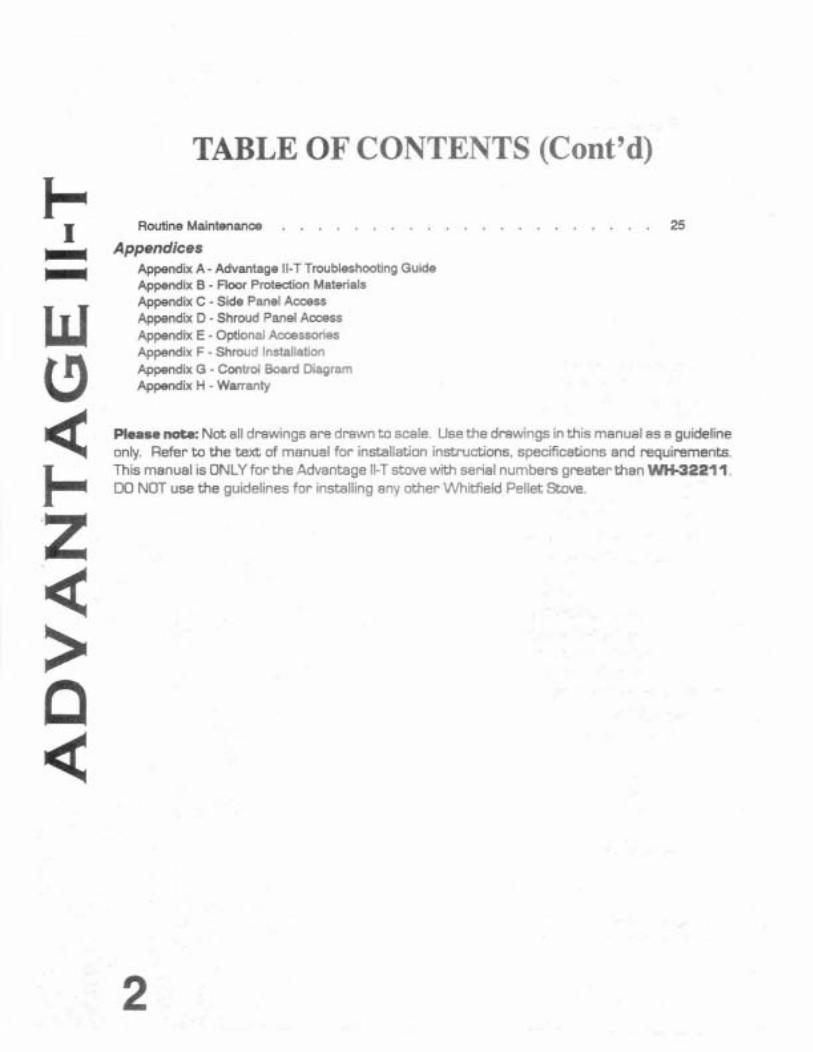
TABLE OF CONTENTS (Cont'd)
Routine Maintenance . . . . . . . . . . . . . . . . . . . . . 25
Appendices Appendix A - Advantage ll-T Troubleshooting Guide Appendix B - Floor Protection Materials Appendix C - Side Panel Access Appendix D - Shroud Panel Aocess Appendix E -Optional Accessories Appendix F - Shroud Installation Appendix G - Control Board Diagram Appendix H -Warranty
Please note: Not all drawings are drawn to scale. Use the drawings in this manual as a guideline only. Refer to the text of manual for installation instructions, specifications and requirements. This manual is ONLY forthe Advantage 11-T stove with serial numbers greaterthan WH-32211. DO NOT use the guidelines for installing any other Whitfield Pellet Stove.

SAFETY PRECAUTIONS
SAFETYNOTZCE THlS STOVE MUST BE PROPERLY INSTALLED AND OPERATED IPI ORDER TO PREVENT THE POSSIBILITY OF A HOUSE FIRE. FOR YOUR SAFETY, THE INSTALLATION AND OPERATION INSTRUCTIONS MUST BE STRICTLY ADHEREDTO. CONTACTYOUR LOCAL BUILDING OFFICIALS TO OBTAIN A PERMIT AND INFORMATION ON ANY INSTALLATION RESTRICTIONS AND INSPEC- TION REQUIREMENTS IN YOUR AREA.
INSTALLATION DISCLAIMER THlS STOVE'S EXHAUSTSYSTEM WORKS WITH NEGATIVE COMBUSTION CHAMBER PRESSURE AND A SLIGHTLY PosmvE CHIMNEY PRESSURE. THEREFORE, IT IS IMPERATIVE THAT THE EXHAUST SYSTEM BE AIRTIGHT AND INSTALLED CORRECTLY. SINCE PYRO INDUSTRIES, INC., HAS NO CONTROL OVER THE INSTALLATION OF YOUR STOVE, PYRO INDUSTRIES, INC., GRANTS NO WARRANTY, IMPLIED OR STATED FOR THE INSTALLATION OR MAINTENANCE OF YOUR STOVE, AND ASSUMES NO RESPONSIBILITY FOR ANY CONSEQUENTIAL DAMAGE@).
DETAILED SAFETY PRECAUTIONS Fuel - The W i e l d "Advantage 11-T" is designed and approved for the burning of high quality pelletized, bio-mass fuel only. The burning of solid fuel in other than pellet form is not permitted. Failure to comply with this restriction will void all warranties and the safety listing of the stove.
Cleaning - There may be some build-up of dust and smaller quantiiies of soot or creosote in the exhaust vent and baffles over the bum season:Although this will be minimal under correct cpwation, a precau- tionary inspection (and cleaning if needed) on a regular basis is advisable.
Continuous Operation - Under w e d operation, the Whitfield "Advantage 11-7 cannot be over-fired. Continuous operation at a maximum bum can, however. shorten the l ie of the electrical components @lowers, motors, and electronic controls), and is not recommended. Typical operation at position 4 with operation at position 5 for the coldest periods is considered to be approved operating conditions.
Liquid Flammabks - Gasoline or other flammable liquids must NEVER be used to start or "freshen up* the fire. Kwp all such liquids well away from the stove at all times.
Ashes - Any ashes removed from the WhiMield "Advantage 11-T" must be deposited in a metal container with a tight-fitting lid.The dosed containerof ashes should be placed on anoncombustiblesurface pending final disposal.
Power - The appliance is provided with an 8 foot, grounded ebdrid mrd. This cord should be amnected to a standard, 110 vdt 60 Hz dectkal outlet The approximate power requirement is 200 watts. The power supply cord must be routed to avoid contad with any of the hot or sharp exbrbr surface areas of the stove. In addtion. all W h i "Advantage ll-Tstoves that are installed in amobile home must be elecbically grounded to the steel chassis and bdted to the Rooc in compliance with and accwding to H.U.D. requirements.
Soot Formation - Buming with insufficient combustion air will resun in the formation of soot, which will be -sited in the flue, the heat exchanger, and when the stove vents through the wall, it will stain the W i d e of the house. This is a hazardous situation in addition to being inefficient and a w; cteful use of pellets. Check your stove frequently, and adjust as required.
Auger - Pellet ruel is fed to the bum pot by an auger. This auger is driven by a high torque motor. The auger is capaMe of doing serious harm to fingers. Keep pellets in hopper at all times and keep fingers away from auger. The auger can start at any time while the stove is running.
Smoke Detector - Asmdce detector MUST be installed in the vicinity of the stove.
Please Note: Disconnect Power Before Doing ANY Routine Maintenance

SAFETY TESTING
In accordance with the specifications and procadures listed in UL 1482 foc solid fuel room heaters, the Whitfield "Advantage II-T' pellet stove has been independently tested and listed by Wamodc Hersey, an accredited testing laboratory (by ICBO & Standards Council of Canada). UL 1482 states requirements for installation as afreestanding room heater, or hearth inser! for masonryor metal (zeroclearance) 5replaces. The safety listing label is located inside the hopper, on the lid. Please read this safety label carefully. It contains important information about instailation and operation of your Whitfield Pellet Stove. This Cwnet's Manual is provided to you to supplement, not replace or update, the infomation contained on the safety
I labei. Note that your stove's seriai number is located on this label. Your stove's serial number is precaded by aNWH-".
This appliance is designed specifically for use only with pelletized fuels. It is tested and listed for residential installation according to cunent national and local building codes as:
Frwstanding Room Heater
W Hearth Insert when installed on the hearth of, or into a masonry or factory bulk fireplace
A Built-in Heater
A Mobile Home Heater
Note: This stove is not intended for use in commercial installations other than where the stove is being sold.
The stove will not operate using natural draft, nor without a power source for the blower and fuel feeding systems. The applianoe is provided with an exhaust connector for a 3 inch type "PL" double wall vent pipe with stainless steel inner liner (on freestanding 8 built-in), or single wall, stainless steel rigid or flexible pipe (for insert).
T
WHITFIELD ADVANTAGE 11-T PELLET STOVE SAFEZTY LABEL
figure 1
Whitfield pellet stoves and fireplace inserts are safety tested and listed by Wamodc Hersey Professional Services. Ltd.
PELmTS - IMPORTANT: PLEASE R;EAD
GENERAL INFORMATION The Whiield Advantage 11-T has been designed to burn wood pellets only. Ditiyfuel will adversely affect the performance of the stove. Caution: The use of dirty, wet and/or salty fuel may void the warranty1
Only wood pelbts manufactured tothe Assodation d Pellet Fuel Industries (A.P.F.1) standard for residential pellet fuels are recommended for use with the Whitfield Advantage 11-T stove. Look for the A.P.F.I. registration number on the bag of fuel to ensure compliance with the standard. Contact your dealer for more information on A.P.F.I. approved wood pellet fuels. T
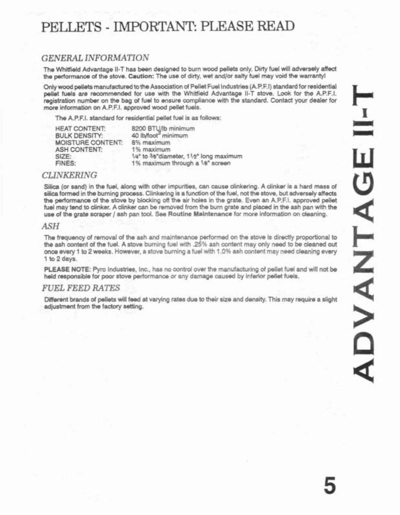
The AP.F.1. standard for residential pellet fuel is as follows:
HEAT CONTENT 8200 BTYb minimum BULK DENSITY: 40 lb/foot minimum MOISTURE CONTENT 8% maximum ASH CONTENT: 1 % maximum SIZE: 1/4" to Wdiameter, 1 lh" long maximum FINES: 1 Oh maximum through a 'h" screen
CLINKERING Silica (or sand) in the fuel, along with other impurities, can cause dinkering. A dinker is a hard mass of silica formed in the burning prooess. Clinkering is atunction of the fuel, not the stove, but adversely affects the perfwmanca of the stove by blddng off the air holes in the grate. Even an A.P.F.I. approved pellet fuel may tend to dinker. Adinker can be removed from the burn grate and placed in the ash pan with the use of the grate scraper / ash pan tool. See Routine Maintenance for more information on deaning.
ASH The frequency of removal of the ash and maintenance performed on the stove is directly proportional to the ash content of the fud. A stove burning fuel with .25% ash content may only need to be cleaned out mca evety 1 to 2 weeks. However, a stove buming a fuel with 1 .O% ash cantent may need deaning every 1 to 2 days.
PLEASE NOTE: Pyro Industries. Inc., has no control over the manufacturing of pellet fuel and will not be held responsible for poor stove performance or any damage caused by infer& pellet fuels.
FUEL FEED RATES Different brands of pellets will feed at varying rates due to their size and density. This may require a slight adjustment from the factwy setting.
STOVE INSTALLATION
STOVE INSTALLATION CHECKLIST
Check off each i t em as you go through your installation.
As part of the installation process It is suggested that you have an authorized Whitfield dealer install your stove. If you install the
stove yourself, you should review your installation plan with the Authorized Whiield Deakr you purchased your stove from.
Take 15 -20 minutes to read the ENTIRE Stove Installation section.
Read the Insert or Freestanding Sections (whichever is appropriate).
Determine the appropriate measurements and locations for your installation.
Follow the installation directions under Stove lnstallation &the lnstallation section appropriate to your stove type (Freestanding or Insert)
Be sure to pre-fit your items before you install, screw in, or set up the stove permanently.
Prior to lighting your stove: Review the Safety Precautions section.
Review the Pellets Section.
Review the Operating Instructions.
Follow the Operating Instructions.
After you have begun operation of your stove: Review the Routine Cleaning / Maintenance information
Enjoy the warmth from your new Whitfield Advantage 11-1 Pellet Stove !
PRE INSTALLATION ASSEMBLY 1. After removing the packaging from the stove, lift the hopper lid, and remove all prepackaged items from the hopper. Also open the combustion chamber door and remove all pr*packaged items.
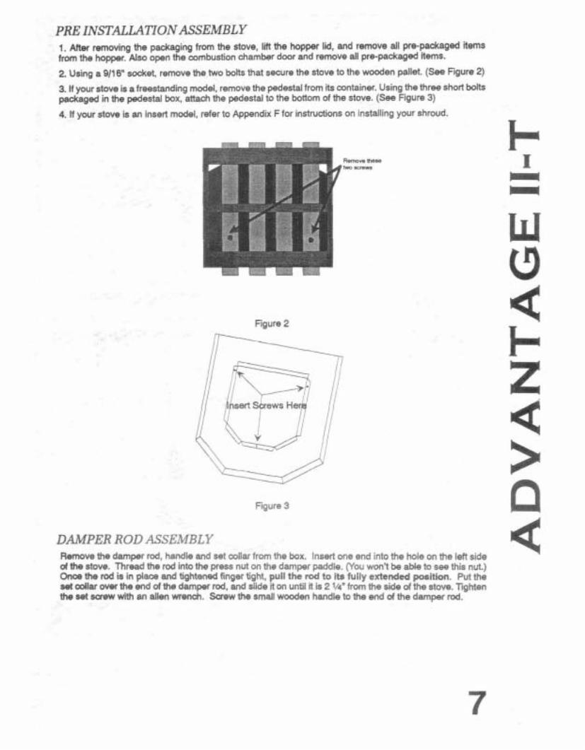
2 Using a 9/16" socket, remove the two bolts that secure the stove to the wooden pallet. (See Figure 2)
3. If your stove is a freestanding model, remove the pedestal from its container. Using the three short bolts packaged in the pedestal box, attach the pedestal to the bottom of the stove. (See Figure 3)
4. If your stove is an insert model, refer to Appendix F for instructions on installing your shroud.
Figure 2
Figure 3
DAMPER ROD ASSEMBLY Remove the damper rod, handle and set collar from the box. Insert one end into the hole on the left side d the stove. Thread the rod into the press nut on the damper paddle. (You won't be able to see this nut.) Once the rod is in place and tightened finger tight, pull the rod to its fully extended position. Put the set collar over the end of the damper rod, and sl~de it on until it is 2 1/4" from the side of the stove. Tighten the set saew with an allen we&. Screw the small wooden handle to the end of the damper rod.

STOVE W7NDOW TRIM INSTALIATION Three window dips are provided. Only one dip is needed for eacfi piece of window trim.
1. Turn the trim dip sideways and put the "Tee" end of the window clip into the window trim. See Figure 4.
2. Spin the trim clip around and place the "straightm end of the dip in the channel on the window trim. Make sure that the tooth is towards the window for a better hold. See Figure 5.
Figure 4
!
Figure 5
3. The window trim clip should go on the trim in the position shown below. Place the bottom of the trim into the window opening first and press firmly until the top of the window trim slips into the window opening. See Figure 6.
4. Next, remove the ash pan trim piam from As container. Attach it to the bottom front of the stwe. The ash pan trim is attached using the two magnets mounted on either side of the ash pan trim piecs. (See Figure 6)
Install Clips Here t l : ~~I ~4
Figure 6
STOVE INSTALLATION CONFIGURATIONS THE WHITFIELD ADVANTAGE 11-1 MAY BE INSTALLED AS:
A freestanding unit with a pedestal placed on a non-combustible floor pad.
A hearth placed fireplace insert into a masonry or factory built fireplace.
A built-in heater placed on an insulated floor pad.
A mobile home heater placed on a non-combustible floor pad and bolted and grounded to the floor of the home.
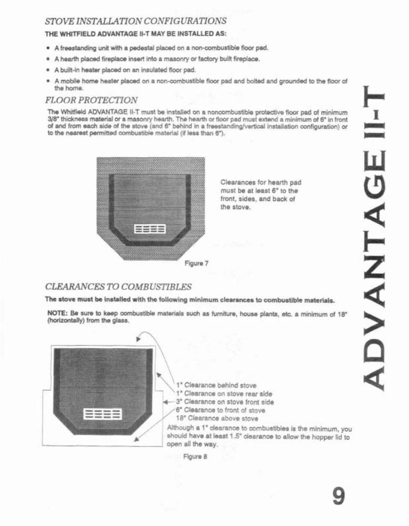
FLOOR PROTECTION The Whitfield ADVANTAGE ll-T must b installed on a noncombustible protective floor pad of minimum 318" thickness material or a masonry hearth. The hearth or floor pad mud extend a minimum of 6" in front of and from each side of the stove (and 6" behind in a freestandinalvertid installation confiauration) or -. to the nearest permitted combustible material (if less than 6").
-
Clearances for hearth pad must be at least 6" to the front, sides, and back of the stove.
CLEARANCES TO COMBUSTIBLES The stove must be installed with the following minimum clearances to combustible materials.
NO= Be sure to keep combustible materials such as furniture, house plants, etc. a minimum of 18" (horizontally) from the glass.
-\' 1" Clearance behind stove ' 1" Clearance on stove rear side 3" Clearance on stove front side 6" Clearance to front of stove 18' Clearance above stove
I Although a 1" dearancs to mmbustibles is the minimum, you 1 shwfd have at least 1.5" dearance to allow the hoooer lid to
I r c
I open all the way.
Figure 8

STOVE EXHAUST / INTAKE INSTALLATlON IT IS RECOMMENDED THAT ONLY AN AUTHORIZED DEALER INSTALL YOUR PELLET STOVE.
THE FOLLOWING INSTALLATION GUIDELINES MUST BE FOLLOWED TO ENSURE CONFORMITY WITH BOTH THE SAFETY LISTING OF THE STOVE AND LOCAL BUILDING CODES.
GENERAL GUIDELINES FOR INSTAUNG EXHAUST SYSTEM Alisted 3 or 4 inch type "PL" pellet vent exhaust system must be used for FREESTANDING installations and attached to the pipe connector provided on the back of the stove. Use a 3-to-4 inch adapter for 4 inch pipe. The vent termination must be located no less than 60" from any opening through which combustion products could enter the building. (i.e. windows and doors) not less than 24" from an adjacant building, and not less than 7' above grade when located adjacent to public waliways. The exit terminal must be arranged sothat flue gases are not directed so as to jeopardize people, oveheat mbust ible structures or enter the building. Keep brush, plants and shrubs at least 36" away from vent termination.
Ninety-degree elbows accumulate fly ash and soot thereby reducing exhaust flow and performance of the stove. Horizontal runs of pipecollect fly ash also. It is recommended that a single or doubledean-out 'tee' be installed at every 90 degree turn so that fly ash can accumulate at the bottom of the 'tee'. If a 90 degree turn connects a vertical run of pipe to a horizontal run (as you follow the exhaust away from the stove), a tee is not required. At any other 90 degree tum, installation of a dean out tee is recommended to permit periodic deaning of both the horizontal and vertical runs of pipe.
Total length of horizontal vent must not exceed 25 it.
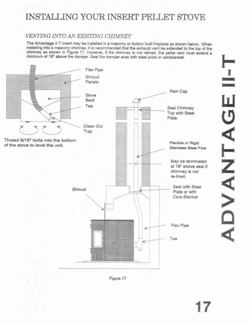
A 3" singlewall, stainless steel flexible or rigid exhaust pipe should be used for INSERT installations and must be attached to the stove with a single or double wall. stainless 'tee' with a clean-out cap. The stainless steel 'tee' can be inclined at 45 degrees to enable the vent to be cantered on the stove, and allows the 'tee'to be deaned out without removing the stove (see Figure 17 on page 17).
When venting into an existing chimney (masonry or factory built) the chimney must be deaned. with all creosote removed.
The "PL" vent or single wall stainless exhaust system must be installed so as to be GAS TlGKTl The vent manufacturer's installation procedures must be followed. In addition, pipe connections, joints and all pipe seams within the home should be sealed with room temperature vulcanizing, high temperature silicone sealer (RTV).
If an insert is to be installed into an unlined masonry chimney, it is recommended that the 3" w stsinless steel pipe be extended to the top of the existing chimney. The top of the existing chimney should be sealed with a steel plate (see Figure 17 on page1 7 ).
CAUTION: On all direct vent installations, care should be taken when choosing a loution for terminating the vent. It is not recommended to directly vent the exhaust on the prevailing wind side of the house. This type of installation may cause a burn back in the stove during a power outage. This may cause serious harm to persons or property.
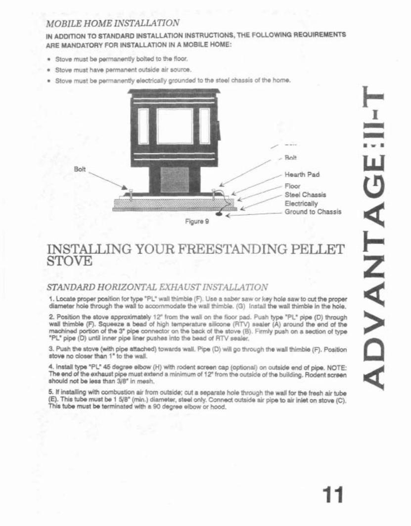
MOBILE HOME INSTALLATION IN ADDITION TO STANDARD INSTALLATION INSTRUCTIONS, THE FOLLOWNG REQUIREMENTS ARE MANDATORY FOR INSTALLATlON IN A MOBILE HOME:
Stove must be permanently bolted to the floor.
Stove must have permanent outside air source.
Stove mus? be permanently electrically grounded to the steel chassis of the home
Bolt Hearth Pad
Floor Steel Chassis Electrically Ground to Chassis .
Figure 9
INSTALLING YOUR FREESTANDING PELLET STOVE
STANDARD HORIZONTAL EXHAUST INSTALLATION 1. Locate proper position for type "PL' wall thimble (F). Use a saber saw or key hole saw to cut the proper diameter hole through the wall to accommodate the wall thimble. (G) Install the wall thimble in the hole.
2. Position the stove approximateiy 12" from the wall on the floor pad. Push type "PL" pipe (D) through wall thimble (F). Squeeze a bead of high temperature silimne (RTV) sealer (A) around the end of the machined poction of the 3" pipe connector on the back of the stove (5). Firmly push on a sedion of type "PC pipe (D) until inner pipe liner pushes into the bead of R N sealer.
3. Push the stove (with pipe attached) towards wall. Pipe (D) will go through the wall thimble (F). Position stove no doser than 1" to the wall.
4. Install type "PL" 45 degree elbow (H) with rodent screen cap (optional) on outside end of pipe. NOTE: The end of the exhaust pipe must extend a minimum of 12" from the outside of the building. Rodent sween should not be less than 318" in mesh.
5. If installing with combustion air from outside: cut a separate hole through the wall for the fresh air tube (E). This tube must be 1 5/8" (min.) diameter, steel only. Conned outside air pipe to air inlet on stove (12). This tube must be terminated with a 90 degree elbow or hood.

I- F A H
A) Use RTV Sealer I B) Pipe Connector on Stove C) Air Inlet on Stove D) 3" Diam.Horizontal Pipe E) Fresh Air Tube
W F) Wall Thimble G) Hole in Wall
13 4 I- 25'
K x
/ Rear of Stove z ' T !
31 318" 4 > P . . . . .. . . . . . . . . . . . . . . . . . . .. .. . . . . . . . . . . . . .
;n;
! :
9 '
i Y / \ Y
(Dimensional tdersnoc: +I- 1/47
Figure 11
< i t t I 2 . ?-! '5 5114. '
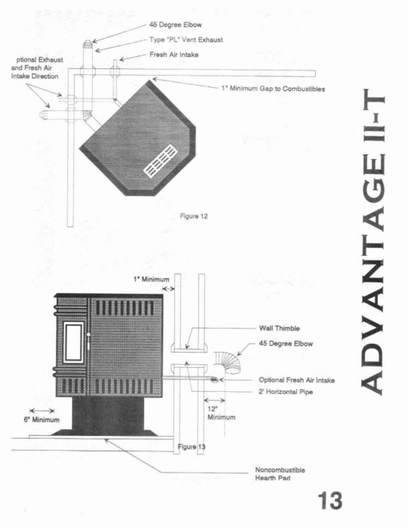
, 45 Degree Elbow
Fresh Air Intake ptional Exhaust
.. . ~ .- --4
------ 1 "Minimum Gap to Combustibles
I
I I Figure 12 ii
Wall Thimble
45 Degree Elbow
Optional Fresh Air Intake
2' Horizontal Pipe
Noncombustible Hearih Pad

DETERMINING EQUrVALENT PIPE LENGTH To determine whether a 3" or 4" exhaust system is required for your installation (freestanding or insert), review the sample installation below. Fill out the top chart, and calculate your total equivalent pipe length. After you have the total equivalent pipe length, use the h a l t at the bottom of the page to determine if your installation requires 3" or 4" exhaust pipe.
A - 90 Deg. Elbow B - 1' Horizontal Pipe E C - 45 Deg. Elbow D - 8' Vertical Pipe E - 2' Horizontal Pipe
F
F - 90 Deg. Tee
1 2 3 4 5 6 7 8 9 ro Altitude in Thousands of Feet
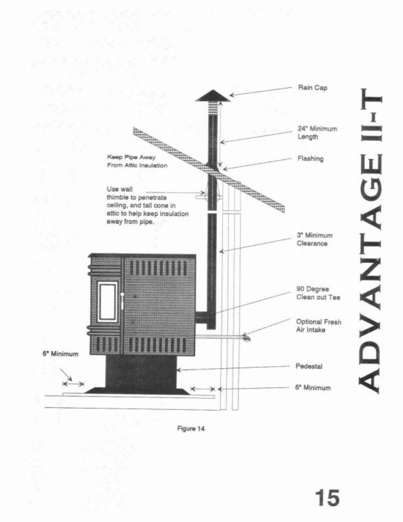
Rain Cap
U U Fgure 14
24" Minimum Length
Flashing
3" Minimum Clearanca
90 Degree Clean out Tee
Optional Fresn Air Intake
Pedestal
6" Minimum
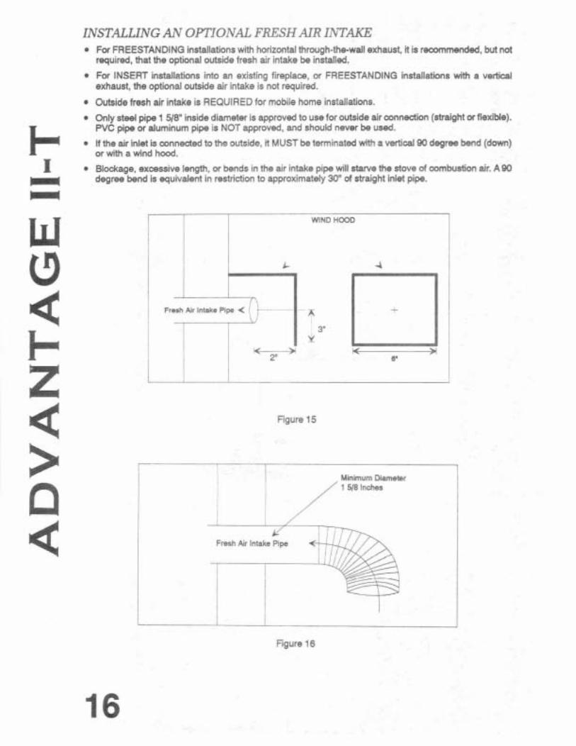
INSTALLING AN OPTIONAL FRESH AIR INTAKE For FREESTANDING installations with horizontal through-thewall exhaust, it is recommended, but not required, that the optional outside fresh air intake be installed.
For INSERT installations into an existing fireplace, or FREESTANDING installations with a v e M exhaust, the optional outside air intake is not required.
Outside fresh air intake is REQUIRED for mobile home installations.
Only steel pipe 1 518" inside diameter is approved to use for outside air m n e d i (straight orflexible). PVC pipe or aluminum pipe is NOS approved, and should never be usad.
If the air inlet is connected to the outside, it MUST be terminated with a vertical 90 degree bend (down) or with a wind hood.
Blockage, excassive length, or bends in the air intake pipe will starve the stove of combustion air. A90 degree bend is equivalent in restriction to approximately 30" of straight inlet pipe.
! I i WIND HCOD
I i
i ~resh ~ i r intake Pipe < i t ~ . . ~ ~ ~ ~ ~ ~ ~ ~ .... ~ +
! I -1 j Y - 2" 6
Figure 15
Minimum Diameter
I
Fresh Air Intake Pipe
Figure 16
INSTALLING YOUR INSERT PELLET STOVE
VENTING INTO AN EXISTING CHIMNEY The Advantage 11-T insert may be installed in a masonry or factory built fireplace as shown below. When installing into a masonry chimney, it is remmmended that the exhaust vent be extended to the top d the chimney as shown in Figure 17. However, if the chimney is not relined, the pellet vent must extend a minimum of 18" above the damper. Seal the damper area with steel plate or cerablanket.
Flex Pipe
Shroud Panels
Rain Cap Stove Back Tee Seal Chimney
Top with Steel Plate
I " . - L 3 u l Clean Out
Trap
Thread 9/16" bolts into the bottom of the stove to level the unit.
nexlble or Rlgld Stalnleslt Steel Pipe
1 L May be terminated
at above seal if
I I chimney is not
Shroud I I
' u
re-lined.
Seal with Steel Plate or with Cera-Blanket
Flex Pipe
Tee
Figure 17
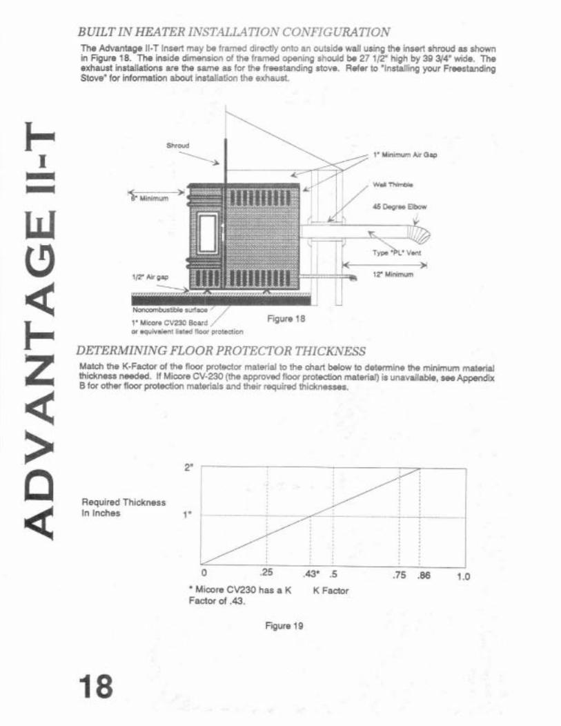
BUILT IN HEATER INSTALLATION CONFIGURATION The Advantage ll-T Insert may be framed directly onto an outside wall using the insert shroud as shown in Figure 18. The inside dimension of the framed opening should be 27 112" high by 39 314"wide. The exhaust installations are the same as for the freestanding stove. Refer to "Installing your Freestanding Stove" for information about installation the exhaust.
Shroud 1' Minimum Air Gap
w.l nlmb*
F:". 1' Micwe CV230 Bcar-l .' re 78 or equivalent listed flour protenion
DETERMINING FLOOR PROTECTOR THICKNESS Match the K-Factor of the floor protector material to the chart below to determine the minimum maten'.al thickness needed. If Miwre CV-230 (the approved floor protection material) is unavailable, see Appendix B for other floor protection materials and their required thicknesses.
Required Thickness In Inches
.75 .86 1 .O
* Micore CV230 has a K K Factor Factor of .43.
Figure 19
THERMOSTAT INSTALLATION/CONTROL PANEL REMOVAL
UNPLUG STOVE BEFORE PERFORMING ANY MAINTENANCE WORK.
The elechoniccontrol board is mounted to an aluminum bracket for easy installation into the stove or side shroud using a single fastener. The wntrol board can be removed or replaced without removing the side panel or the side shroud.
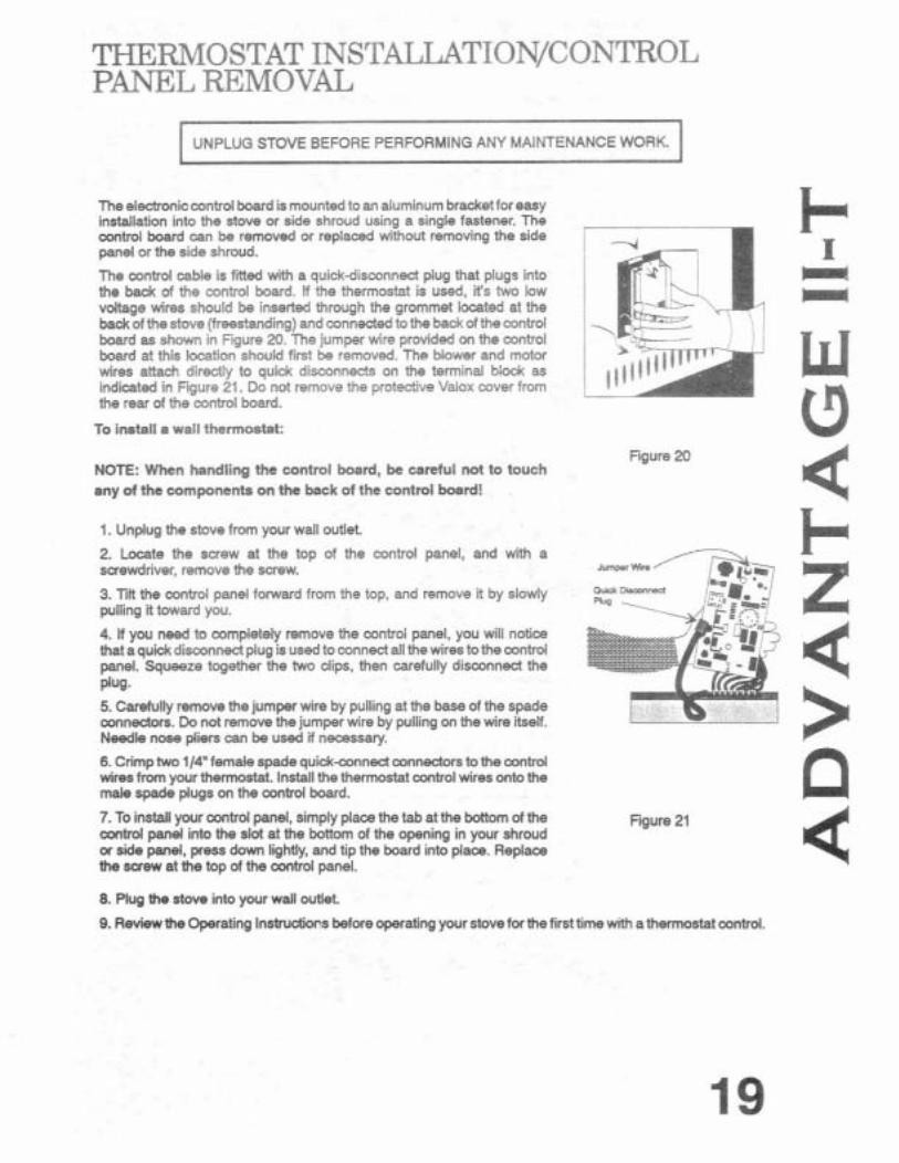
The control cable is fMed with a quick-disconnect plug that plugs into the back of the control board. If the thermostat is used, ifs two low voltage wires should be inserted through the grommet located at the back of thestove (freestanding) and connected to the badtof the control board as shown in Figure 20. The jumper wire provided on the control board at this location shauld first be removed. The Mower and motor wires attach directly to quick disconnects on the terminal block as indicated in Rgure 21. Do not remove !he protective Valox cover from the rear of the cnntrol board.
To install a waIl thermostat:
Figure 20 NOTE: When handling the control board, be careful not to touch any of the components on the back of the control board!
I. Unplug the stove from your wall outlet.
2. Locate the screw at the top of the control panel. and with a screwdriver, remove the screw.
3. Tilt the control panel forward from the top, and remove f i by slowly w- pulling it toward you.
4. If you need to completely remove the control panel, you will notice that a quick disconnect plug is used to connect all thewires to the wntrol panel. Squeeze together the two dips, then carefully disconnect the plug. 5. Carefully remove the jumper wire by pulling at the base of the spade connectors. Do not remove the jumper wire by pulling on the wire itself. Needle nose pliers can be used il necassary.
6. Crimp two 114" female spade quid-connect connectofs to the control wires from your thermostat. Install the thermostat control wires onto the male spade plugs on the control board.
7. To install your contrd panel, simply placa the tab at the bottom of the control panel into the slot at the bottom of the opening in your shroud or side panel, press down lightly, and tip the board into place. Replace the screw at the top of the control panel.
Fgure 21
8. Plug the stove into your wall outlet.
9. Review the Operating Instructions before operating your stove for the firsttime with athermostat contrd.
While on thermostat operation, the stove operates under two settings. There is a "pilot" (low) setting and a "demand" (high) setting.
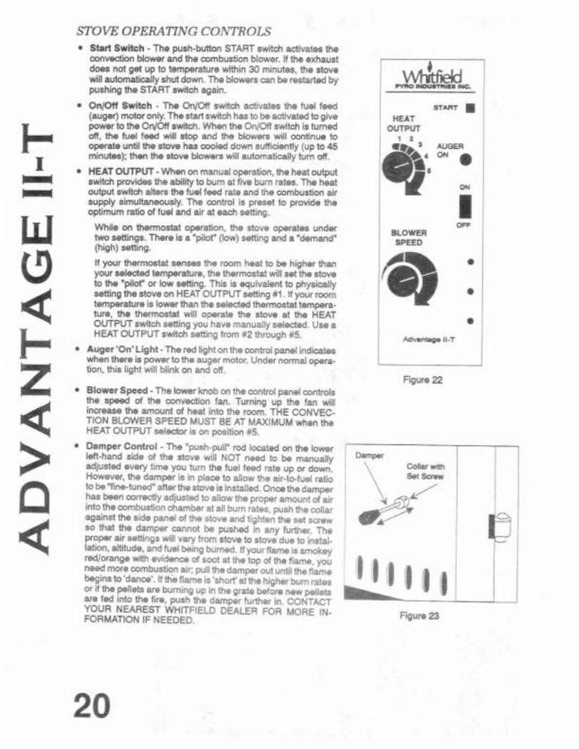
STOVE OPERATlNG CONTROLS Start Switch - The push-button START switch activates the convection blower and the combustion blower. If the exhaust does not get up to temperature within 30 minutes, the stove will automatiilly shut down. The blowers can be restarted by
If your thermostat senses the room heat to be higher than your selected temperature, the thermostat will set the stove to the "pilot" or low setting. This is equivalent to physically setting the stove on HEAT OUTPUT setting #I. If your reem temperature is lower than the selected thermostat tempera- ture, the thermostat will operate the stove at the HEAT
pushing the START switch again.
On/Off Switch - The On/Ofl switch activates the fuel feed (auger) motor only. The start switch has to be activated to give power to the OnIOff switch. When the OnIOff switch is turned off, the fuel feed will stop and the blowers will continue to operate until the stove has cooled down sufficiently (up to 45 minutes): then the stove blowers will automatically turn off.
HEAT OUTPUT - When on manual operation, the heat output switch provides the ability to bum at five burn rates. The heat output switch alters the fuel feed rate and the combustion air supply simultaneously. The control is preset to provide the optimum ratio of fuel and air at each setting.
OUTPUT switch setting you have manua.ly selectee. Use a HEAT OUTPJT swttch setting from *2 tnrough k5 .
mn lNDUSTRa8 INC.
ST- . HEAT
OUTPUT i a
Auger 'On' Light - The red light on the control ane el indicates
OFF BLOWER SPEED
when there is power to the aiger motor. ~nde; normal opera- tion, this liaht will blink on and off.
L -
Figure 22 Blower Speed -The lower knob on the control panel controls the speed of the convection fan. Turning up the fan will increase the amount of heat into the room. THE CONVEC- TION BLOWER SPEED MUST BE AT MAXIMUM when the HEAT OUTPUT selector is on position #5.
Damper Control - The "push-pull" rod located on the lower left-hand side of the stove will NOT need to be manually adjusted every time you turn the fuel feed rate up or down. However, the damper is in place to allow the air-to-fuel ratio to be "fine-tuned" afterthe stove is installed. Once the damper has been comedly adjusted to allow the proper amount of air j into the combustion chamber at all burn rates, push the cdlar i against the side panel of the stove and tigh!en the set screw I so that the damper cannot be pushed in any further. The i proper air settings will vary from stove to stove due to instal- ~ lation, aititude, and fuel being burned. If yourflameis smokey 1 redlorange with evidence of soot at the top of the flame, you need more combustion a;r: pull the damper out until the flame begins to 'danca'. If the flame is 'short' at the higher bum rates or if the pellets are burning up in the grate before new pellets are fed into the fire, push the damper futther in. CONTACT I YOUR NEAREST WHITFIELD DEALER FOR MORE IN- FORMATION IF NEEDED. Figure 23

OPERATING INSTRUCTIONS
PRE-LIGHTING INSTR UCTIONS When lighting your Whiield Advantage Il-T Pellet Stove for the first time, the auger feed tube has to be primed with pellets.
To prime the auger feed tube:
1. Fill the hopper with recommended pellet fuel and plug the stove into the wall outlet.
2 Press the start switch on the conbd panel. This will adhrate both blowers. Tum the ONIOFF switch on the control panel to the 'ON' position. This will activate the auger motor. Next, tum the heat output switch
I to msition #5 lmaximum feed rate). I - r- - -
3. Look through the combustion chamber door and when you see the first pellets dropping into the grate m the auper is then fully primed. It will take 10 to 20 minutes to prime the auger. - 4. Once the auger is primed, unplug the stove to tum off the blowers and auger. You need only do this when priming the auger. Once the stove is shut down, plug it in the wall again.
STARTING YOUR WHITFIELD PELLET STOVE W
IAi 1. P k e a rearnmsnded fue stater (see your dealer for appropmte fKastarter ~n ywr area) cn the bum grate and pr( a handful of pellets on top d Gw starter DO NOT USE FLAMMABLE UQUIDS TO START YOUR STOVE.
2. Light the firestarter in the grate with a match and dose the door. Turn the heat output selector switch to position 3.
3. After approximately one minute, press the start switch. You will notice that the fire will become active and there will be air coming from the heat exchanger tubes.
4. After the pellets in the grate are burning sufficiently (red hot coals), slide the ONIOFF switch tothe "ONn
motors will continue to operate. F- position: this will activate the auger motor, and pellets will begin to feed into the bum grate. Your blower a
6. After the pellets are buming well, adjust the HEAT OUTPUT selector to the desired setfing. Combustion air and the pellet fuel feed rate will adjust automatically as the HEAT OUTPUT selector switch is turned. The flame should be bright yellow in color and there should be no evidence of soot formation at the top of the flame. Adjust the Mower speed control knob to increase or decrease the desired amount of convection air from your stove.
Z If operating your stove kith a wall thermostat, adjust the heat output selector switch to the desired demand mode (#2 through #5 on the heat output selector switch). Next, adjust the wall mounted thennostat to the
4 desired heat and your stove will automatically switch itself between a demand mode and a pilot mode.
GENERAL OPERATING CONSIDERATIONS PROPER BURN CHARACTERISTICS: Your flameshould be bright yellow under normal operation. If your flame becomes reddish/orange, your stove probably needs routine maintenance. Excessive amounts of
> fly-ash build-up in the stove, dinkers in the grate, or leakage between the grate and the bum pot will .$tap:= the fire for air. (See ROUTINE MAINTENANCE for infwmation on cleaning the stove). If the problem persists review the trwbleshcding section at the end of this manual.
Dl PEUET FEED: The pelbt feed system is designed to handle a wide range of pellet sizes. Different pellets can feed at considerably different rates. If the stove will not stay alight at the minimum fuel feed setting, those patlkular pellets are not feeding fast enough. If this happens, have your Whitfield dealer adjust the "AUGER ON" time on your stove. At the same time, the dealer may need to adjust the blower speed. Note: There may be a nominal senrice charge tor this servica.
PEUET SIZE: You may notice a difference in the bum if you change pellet fuel sizes. The bigger the pellet, the slower it will feed and vice versa.
LONG BURN TIME: The stove may be safely operated on acontinuous basis, but it is recommended that it be turned down overnight or when the room is vacated for long periods of time. A40 Ib. bag of peilets should last approximately 10 hours on high and 35 hours (or more) on low, depending on the type and size d pellets you are buming.
AUTOMATIC SAFETYFEATURES Power Outage
During a power outage, the stove will shut down safely. It will not automatically restart when the power is restored unless the exhaust is still up to temperature. A small amount of smoke may leak from the top of the window glass, the hopper and from the combustion air intake. This wilt not persist for more than 3 to 5 minutes and will not be a safety hazard.
To re-light the stove, follow the normal procedure for starting your stove.
Overheating
A high temperature switch will automatically shut down the stove if it overheats. The stove win need to be manually re-lit Allow 45 minutes before re-lighting.
TURNING OFF YOUR WHITFIELD PELLET STOVE Turn the OnlOtf Switch to the "OFF pcsition. This will turn the auger motor off and pellets will stop feeding. Both blowers will mt inue to operate for a period of time (up to 45 minutes) until the exhaust temperature cools sufficiently. The blowers will automatically turn off.

ROUTINE CLEANING
NOTE: STOVE WILL NEED TO BE SHUT OFF AND COOLED ENOUGH TO HANDLE BEFORE ROUTINE CLEANING IS PERFORMED.
ALWAYS DISCONNECT POWER BEFORE WING ANY ROUTINE CLEANING.
The amount of fly ash build-up in your stove is directly proportional to the ash content of the f w l that you are using (see PELLETS, page 5). After a period of time (a week, or so) inspectthe heat exchangertubes, the burner head, and the ash traps behind the fire brick. You will want to gauge your routine maintenance accordingly.
A ROUTINE MAINTENANCE sticker is located inside the hopper lid of your stove for convenience.
THE FOLLOWING AREAS NEED TO BE INSPECTED DURING ROUTINE CLEANING:
Bum Grate
Bum Pot
Heat Exchanger Tubes
Ash Pan
Ash Traps and Baffles
Bum Grate: The bum grate should be inspected periodicaily to assure that the air holes have not become clogged with ash or clinkers. The burn grate can easily be cleaned with the grate scraperlash pan tool, or it can be removed from the bum pot for deaning.
Bum Pot: The born pot should be removed periodically and emptied of ash.
PLEASE NOTE: The air inlet tube on the burn pot has a ring gasket on the end. This gasket must firmly seat against the badc of the firebox for proper combustion airflow.
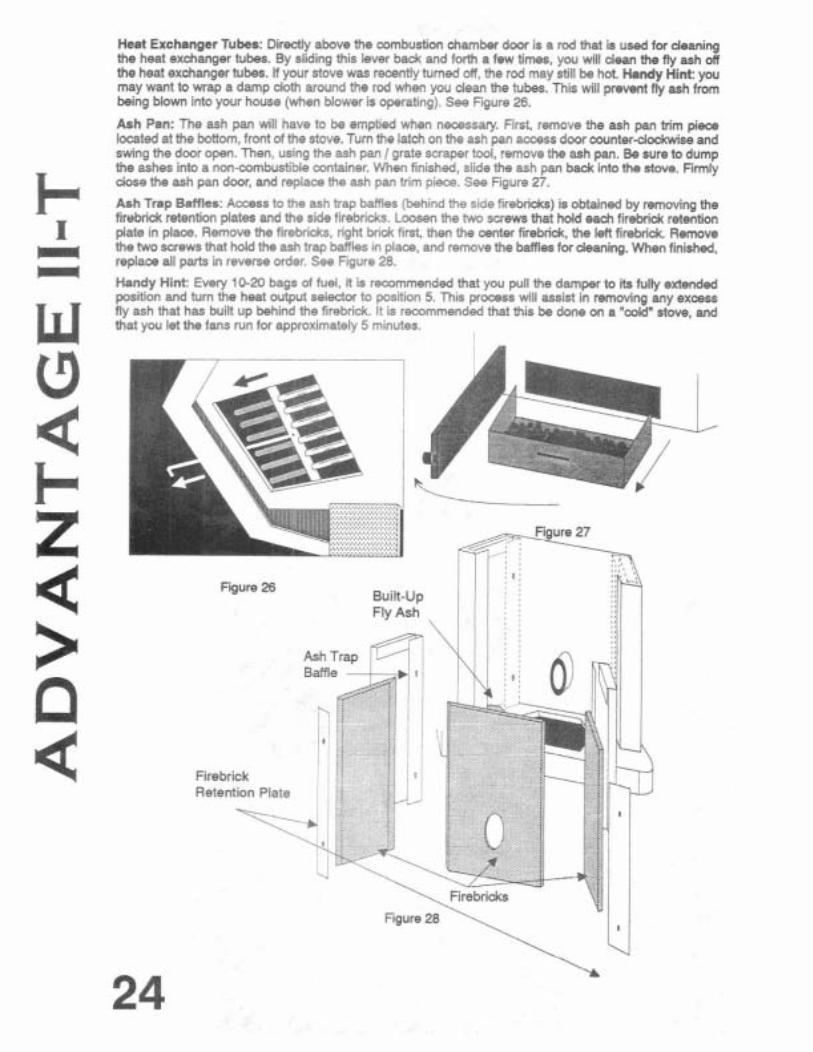
Heat Exchanger Tubes: Directly above the combustion chamber door is a rod that is used for deaning the heat exchanger tubes. By sliding this lever b a d and forth a few times, you will dean the fly ash off the heat exchanger tubes. If your stove was recantly turned of!, the rod may still be hot Handy Hint: you may want to wrap a damp cloth around the rod when you dean the tubes. This will prevent fly ash from being blown into your house (when blower is operating). See Figure 26.
Ash Pan: The ash pan will have to be emptied when necessary. First, remove the ash pan trim pi- located at the bottom, front of the stove. Tum the latch on the ash pan access door wunter-clockwise and swing the door open. Then, using the ash pan 1 grate scraper tool, remove the ash pan. Be sure to dump the ashes into a non-combustible container. When finished, slide the ash pan back into the stove. Firmly close the ash pan door, and replace the ash pan trim piecs. See Figure 27.
Ash Trap BaffIes: Access to the ash trap baffles (behind the side firebricks) is obtained by removing the firebrick retention plates and the side firebricks. Loosen the two screws that hold each firebrick retention plate in place. Remove the firebridts, right hi& first, then the center firebridc, the left firebrick Remove the two screws that hold the ash trap bafles in place, and remove the baffles for deaning. When finished, replace all park in reverse order. See Figure 28.
Handy Hint: Every 10-20 bags of fuel, it is recommended that you pull the damper to its fully extended position and turn the heat output selector to position 5. This process will assist in removing any excess fly ash that has built up behind the firebrick. I! is recommended that this be done on a "wid" stove, and that you let the fans run for approximately 5 minutes.

ROUTINE CLEANING (cont'd) Ash Release Slide Plates: Located behind the left and right side pieces of firebrick are ash traps. Over a period of time, fly ash will accumulate in these ash traps. Fly ash can be easily removed from these areas by using the ash trap side plates located directly behind either side of the burn pot. First, remove the bum pot from the combustion chamber. (See page 23, Figure 25) Next, simply slide the plates back and forth. Fly ash will fall from the ash traps into the ash pan area. See Figure 29 When finished, follow the instructions for accessing the ash pan. Slide the ash pan out a few inches and use the ash pan / grate scrapertool to scrape theashes that fell from the ash traps into the ash pan. Empty the ash into a non-combustible con- tainer. Replace the parts in reverse order.
ROUTINE MAINTENANCE Figure 29
The following areas need to be inspected as part of routine maintenance:
Door Rope Gasket: The mdit ion of the rope gasket around the door and windom shwld be checked periodically and replaced or repaired if necessary. The hinges can be adjusted to improve the door seal.
To Adjust Hinges:
I. Remove the door from both hinges by liiing up on the entire door.
2. Rotate each hinge to make adjustment as needed.
Turn the hinge clodwise to tighten seal, cwnterclockwise to loosen seal.
Figure 30
Exhaust Vent: Inspect frequently and dean when necessary. Fly ash will accumulate at all bends in the exhaust system. Large amounts of fly ash will starve the fire for air. Review Figure 31 fordetails of cleaning out a PL Vent Tee'.
Motor Lubrication: The two Mower motors require lubrication annually with not more than two drops of high temperature turbine oil (available from your dealer) at the lubrication points shown in Figure 32
Figure 31 Figure 32
APPENDIX A TROUBLESHOOTING
UNPLUG STOVE BEFORE PERFORMING ANY MAINTENANCE WORK
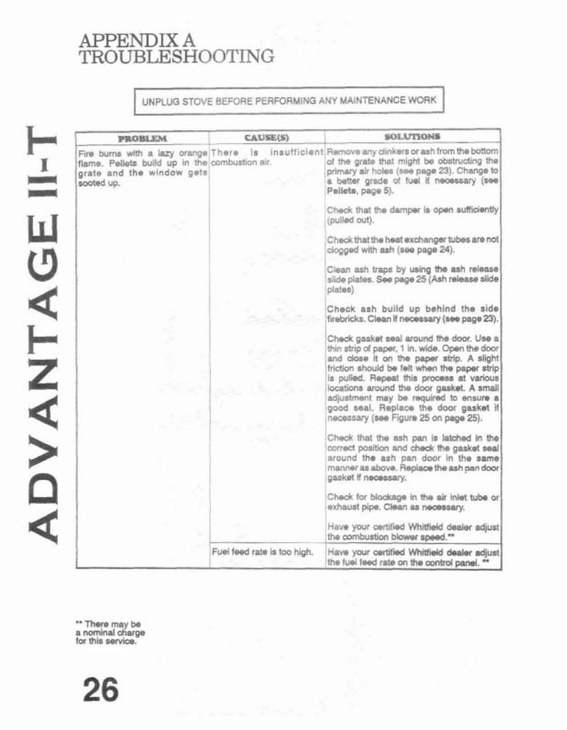
Fire burns wtth a lazy orange flame. Pellets build up in the grate and the window gets
here is insufficient;Fiernoveany dinkersorashfromthe bottom ombustion air. iof the grate that migM be obstructing the
iprimary air holes (see page 23). Change to ja better grade o! fuel if necessary (see !Pellets, page 5).
check that the damper is open sufficiently I (pulled out). !
/ ~ h e c k thatthe heat exchangertubesare not !clogged with ash (see page 24). I /Clean ash traps by using the ash release islide plates. See page25 (Ash release slide
I Check ash build up behind the side firebricks. Clean if necessary (see page 23). I Check gasket seal around the door. Use a thin strip of paper, 1 in. wide. Open the door ,and dose it on the paper strip. A slight 'friction should be felt when the paper strip iis pulled. Repeat this process at various llocations around the door gasket. A small adjustment may be required to ensure a good seal. Replace the door gasket if necessary (see Figure 25 On page 25).
/check that the ash pan is latched in the1 lcorrect position and chedc the gaskel seal 'around the ash pan door in the same Imanner as above. Replaca the ash pan door ;gasket 8 necessav.
I I
/check for blockage in the air inlet tube or lexhaust pipe. Clean as necsssary. I Have your certdled Whield dealer adjust the cambustion blower speed.- ,
uel feed rate is t m high. 'Have your certified Wh- deakw adjust /the fuel feed rate on the control panel.
" There may be a nom~nal charge for this service.
APPENDIX A TROUBLESHOOTING (CONT'D)
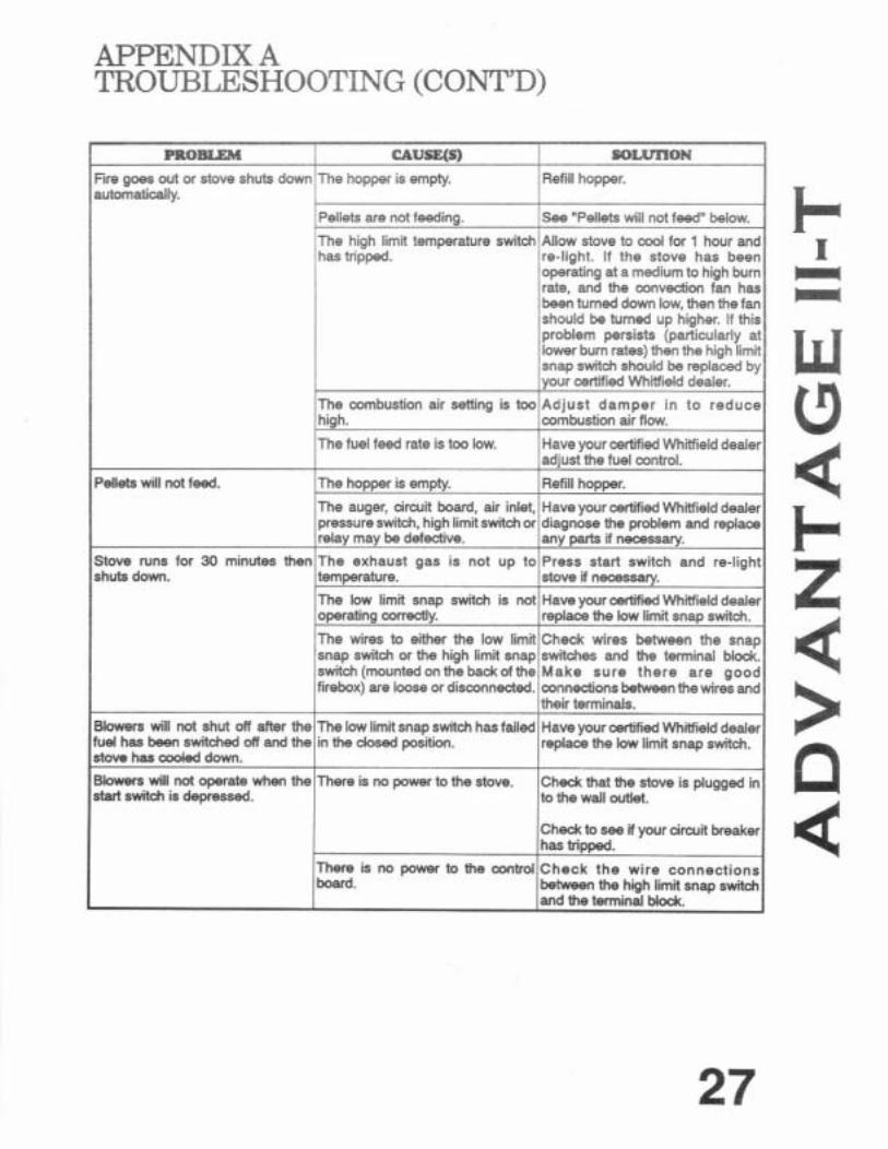
re-light. If the stove has bee operating at a medium to high bur rate, and the mnvedon fan ha been turned down low, then the fa
Blowers will not shut off after the fuel has been switched off and the stove has coded down.
Blowers will not operate w h the start switch is depressed.
operating corrdy.
The wires to either the low limit snap switch or the high limit snap switch(mountedonthebadcofthe firebox) are loose or disconnected.
The low limit snap switch has failed in the dosed position.
There is no power to the stove.
There is no power to the control board.
replaca the low limit snap switch.
Check wires between the snap switches and the terminal Mock. Make sure there are good connections between the wires and their terminals.
Have your cactified W i e l d dealer replaca the low limit snap switch.
Check that the stove is plugged in to the wall OM&.
Check to see if your circuit breaker has tripped.
Check the wire connections between the high limit snap switch and the terminal Mock.

APPENDIX A TROUBLESHOOTING (CONT'D)

APPENDIX B FLOOR PROTECTION MATERIALS
Micore CV-230 is the approved and tested floor protection material. If you need to use a floor protector other than Micore CV-230, see the above chart of equivalent floor protection materials. A K factor is listed for each material type. The minimum thidtness is derived from the chart on page 19. When you insta!! a material listed above, the column labeled "Actual Thickness" gives you the actual thickness of the material you will be using when you utilize the required number of sheets or layers of material. All thickness listings are in inches.
Millboard .84 1 1.95 2
Wonderboard 16 Sheek ot7/16" .98 1 2.27 2.625

APPENDIX C SIDE PANEL ACCESS
Easy accsss side panel
Figure 33
30
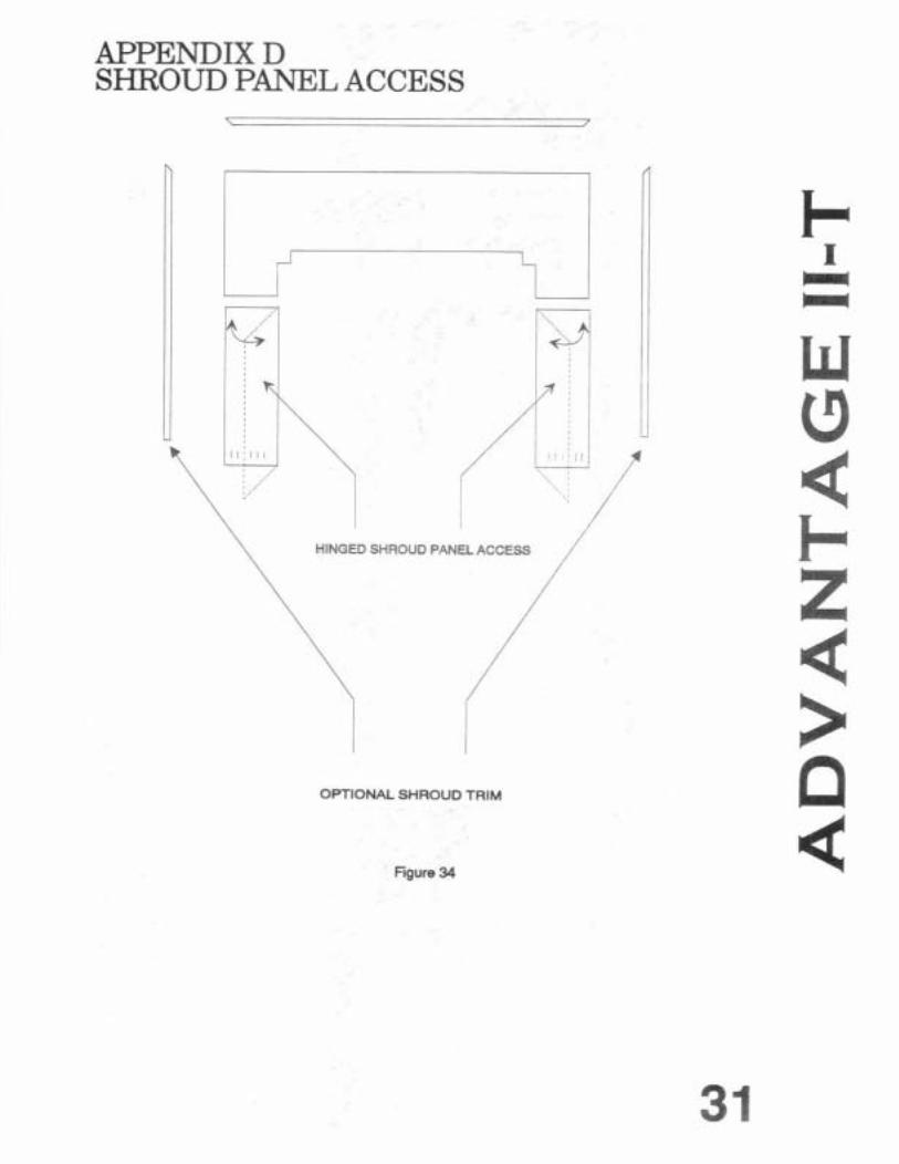
APPENDIX D SHROUD PANEL ACCESS
OPTIONAL SHROUD TRIM
Figure 34

APPENDIX E OPTIONAL ACCESSORIES
A gold plated trivet is available for your Advantage 11-T stove.
Shrouds are available in three sizes for your Advantage 11-T insert.
Small: 28 Vz inches high by 40 3/4 inches wide
Medium: 32 inches high by 4 4 inches wide
a Large: 36 inches high by 47 14 inches wide
An insert pedestal support is available to add height to the shrouds. The pedestal support attaches to an insert stove, and adds between 3 IR inches to 7 inches of additional height. See Fgure below for installation.
Figure 35
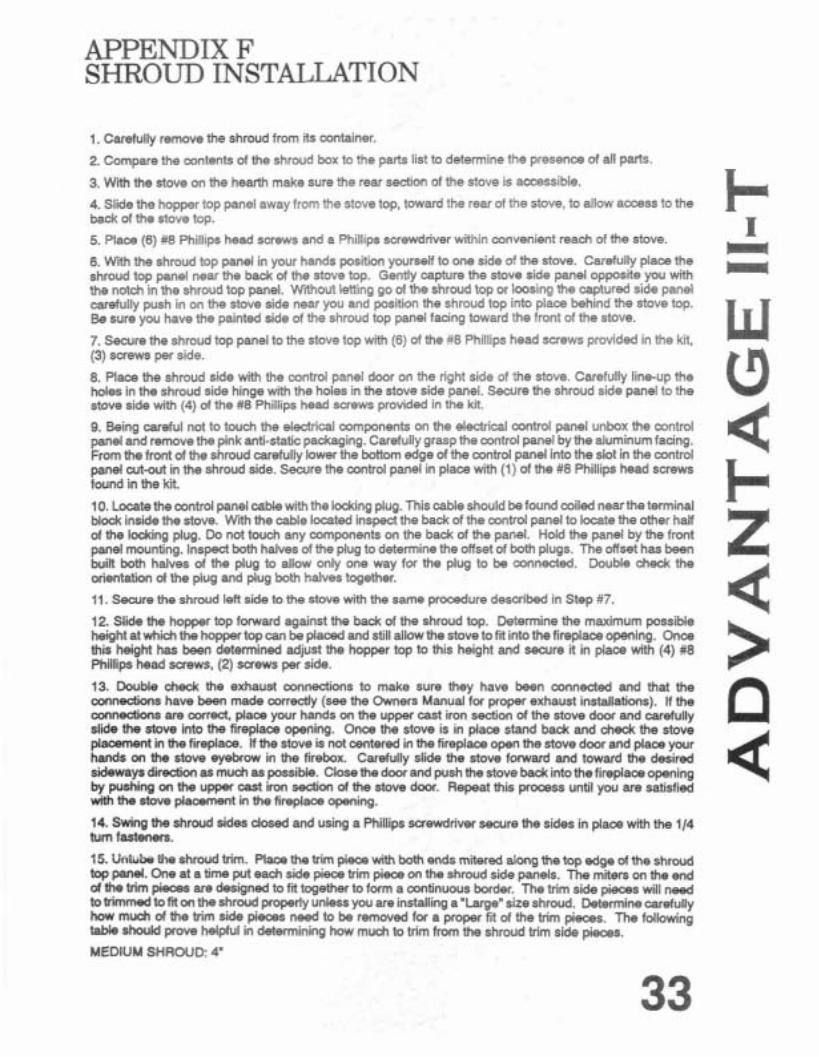
APPENDIX F SHROUD INSTALLATION
1. Carefully remove the shroud from its container.
2. Compare the contents of the shroud box to the parts list to determine the presence of dl parts.
3. With the stove on the hearth make sure the rear section of the stove is accsssible.
4. Slide the hopper top panel away from the stove top, toward the rear of the stove, to allow access to the back of the stove top.
5. Place (6) #8 Phillips head screws and a Phillips screwdriver within convenient reach of the stove.
6. With the shmud top panel in your hands position yourself to one side of the stove. Carefully place the shroud top panel near the back of the stove top. Gently capture the stove side panel opposite you with the notch in the shroud top panel. Wrthout letting go of the shroud top or loosing the captured side panel carefully push in on the stove side near you and position the shroud top into place behind the stove top. Be sure you have the painted side of the shroud top panel facing toward the front of the stove.
7. Secure the shroud top panel to the stove top with (6) of the#8 Phillips head screws provided in the kt, (3) suews per side.
8. Place the shroud side with the control panel door on the right side of the stove. Carefully line-up the holes in the shroud side hinge with the holes in the stove side panel. Secure the shroud side panel to the stove side with (4) of the #8 Phillips head mews provided in the kit.
9. Being careful not to touch the electrical components on the electrical control panel unbox the control panel and remove the pink anti-static packaging. Carefully grasp the control panel by the aluminum facing. From the front of the shroud carefully lower the bottom edge of the control panel into the slot in the control panel cut-out in the shroud side. Sewre the control panel in place with (1) of the #8 Phillips head screws found in the kit.
10. Locate the control panel cable with the lodting plug. This cable should be found coiled nearthe terminal blodc inside the stove. With the cable located inspect the back of the control panel to locate the other hail of the lodting plug. Do not touch any components on the back of the panel. Hold the panel by the front panel mounting. Inspect both halves of the plug to determine the offset of both plugs. The offset has been built both halves of the plug to allow only one way for the plug to be connected. Double chedc the orientation of the plug and plug both halves together.
11. Secure the shroud left side to the stove with the same procedure dexxibed in Step #7.
12. Slide the hopper top fonvard against the back of the shroud top. Determine the maximum possible height at which the hopper top can be placed and still allow the stove to fit into the fireplace opening. Once this height has been determined adjust the hopper top to this height and searre it in place with (4) #8 Phillips head screws, (2) saews per side.
13. Double check the exhaust wnnections to make sure they have been connected and that the connections have been made amectly (see the Owners Manual for proper exhaust installations). If the mnections are correct, place your hands on the upper cast iron section of the stove door and carefully slide the stove into the fireplace opening. Once the stove is in place stand back and &&the stove placement in the fireplace. If the stove is not centered in the fireplace open the stove door and place your hands on the stove eyebrow in the firebox. Carefully slide the stove focward and toward the desired sideways direction as much as possible. Close the door and push the stove back into the fireplace opening by pushing on the upper cast iron section of the stove d m . Repeat this process until you are satisfied with the stove placement in the fireplace opening.
14. Swing the shroud sides d W and using a Phillips screwdriver secure the sides in place with the 114 tum fasteners. .r , , -... L . . I P. UIIWUU rhe shmud trim. Place the trim piece with both ends mitered along the top edge of the shroud top panel. One at a time put each side piece trim pieca on the shroud side panels. The miters on the end of the trim pieces are designed to fit together to form a continuous border. The trim side pieces will need totrimmed to fit on the shroud properly unless you are installing a"Largen size shroud. Determinecarefully how much d the trim side pieces need to be removed for a proper fit of the trim piecas. The following table should prove helpful in determining how much to trim from the shroud trim side pieces.
MEDIUM SHROUD: 4"

SHROUD INSTALLATION (CONT'D)
SMALL SHROUD: 7 14'
These measurements may need to be adjusted for each installation. Therefore the trim p i e m should be cut a little long initially and re-cut as needed. For examp49 for a MEDIUM SHROUD perhaps the side trim pieces should be trimmed initially by 3" then the piece tried on the shroud. Then an additional 112" trimmed and the piece refitted to the shroud. This process shwld be repeated until the side trim pieces fit the shrwd as dosely as possible.
The shrwd trim can be cut with a good pair of common sdsson. The pieces should be art on the square end. Cutting the mitered eM1 will be much more difficult to cut properly without damaging the M of the miters.
16. Insped the installation for proper fff and finish. Once satisfied with the installation properfy dispwe of the packing and shipping material.

APPENDIX G CONTROL BOARD DIAGRAM
-
Figure 36

APPENDIX H - W m
THlS WARRANTY IS ISSUED BY PYRO INDUSTRIES, INC. (MANUFACTURER) AND EXTENDS ONLY TO THE ORIGINAL PURCHASER OF THlS PRODUCT.
The Manufacturer pmvides a five year limited warranty on all steel pa& [except the grate), and a 1 year limited T warrantv on all electrical compments. These warranties extend hwn the date of the wiginsl purchase. There
I- is expressly no warranty on the following components: glass window, fiberglass rope gaskets, firebrick grate. paint, exterior brass or enamel finish.
m
I This warranty m r s defects in materials and workmanship in covered components, pmvided the pmdud has been instelled and operated strictky in accordance with Manufacturer's printed instructjas. This warrenty does not cover damage or breakacage caused by impmper handling, misuse or unauthaized modificatioo. Whhout - limiting the foregoing, the use of fuels other than pelletized wood will void ell warranties and l iabi l is.
All claims under this warranty must be made in M n g to the Manufmcturn at Pym Indussies. Inc. 11 625
w Airport Road, Everett, WA 98204. and should indude the following:
1. Name, address. and t.lephone nunber d ~ e ~ i d n g dealer. 2. Name, address, and telephone number d purchaser.
(3 3. Date d p u r w . 4. Model 6 Serial numkr d stow. 5. Nature d I5-m defed, malfunction and/u complaint.
4 Local represeMatks are ta inspect pahs and a units. If the iwpedm indicates th& the fahm w due to defective materiel orwodmansh'i in wered ~ o o w a s a d t h a t t h e d h e r r a m s a d ~ d t k warranCy have been ccmplii with. the Manufaduer's sde w a n d kbi& under rllis wsna*y sham be Limtad to the Manufacturer's replacement a repair, st Manufacturn's option. of the d&&m ujt or part The
F- purchaser shall assume dl ox& d shippiw to and fmm the M a n u k f a w r and shal tm responsble for d h &ring s h i i n t if the unit is nd defecbire. If a unit is found to be bythe.hbm&cbw, s h i i m ~ s will be reimbursed. RemoMl and reinstabtion costs are nd d under thk w a m q .
1 NEITHER THE MANUFACTURER. NOR THE SUPPLIER TO THE PUR
7 CHASER, ACCEPTS RESPONBIEIUTY. LEGAL OR ONERWI.E, FOR INCIDENTAL OR CONSEQUENTIALDAMACETO PROPERTY OFPER
~ -. -
9 SON= RESULTING FROM THE USE OF THlS PRODUCT. ANY WAR-
9: RAN= IMPLIED BY LAW, INCLUDING BUT NOT LIMITED TO IMPLIED WARRANTIES OF MERCHANTABILITY OR FITNEIm. mHALL PE LIMITED TO ONE YEAR FROM THE DATE OF ORIGINAL PURCHASE. WHETHER A CLAIM IS MADE AGAINST THE MANUFACTURER > EASED ON A BREACH OFTHIS WARRANNOR ANY OTHERTYPEOF WARRANTY, EXPRESSED OR IMPLIED BY LAW, MANUFACTURER SHALL IN NO EVENT BE LIABLE FOR ANY SPECIAL, INDIRECT, CON- SEQUENTIAL OR OTHER DAMAGEB OF ANY N A T U F a k WHAT-
a BOEVER IN EXCESS OF THE ORIGINAL PURCHASE PRICE OF THIS P R O D U C T . ALL WARRANTIES BY M A N U F A C b U W E R ARE BET FORTH HEREIN AND N O CLAIM SHALL BE MADE AGAIN IT MANUFACTURER O N ANY ORAL WARRANTY OR R E P R S SENTATION.
Some states do not allow the exclusion or limitadon of conseqoential damages, a k m i i d impCed warranties, so the lim'btions or exclusions set forch in this warranty may not w l y to yw.
This warranty gives you specific legal rights and you may also have other rights which very hnm Besbe to r*aca.

![Antagonistic interaction of antiwear additives and soot · 2015. 12. 14. · Soot accumulates in the contact inlet and restricts oil supply [9]-[11] 8 : Soot abrades rubbing metal/metal](https://img.pdfslide.us/doc/110x75/60a90c61d577f4301a056df1/antagonistic-interaction-of-antiwear-additives-and-soot-2015-12-14-soot-accumulates.jpg)


![Nanoparticles For Soot Reduction [Div]](https://img.pdfslide.us/doc/110x75/61fbd2699871014c47523f3a/nanoparticles-for-soot-reduction-div.jpg)