Embed Size (px)
Citation preview
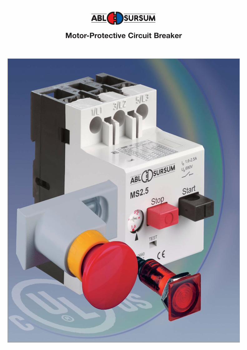
Motor-Protective Circuit Breaker
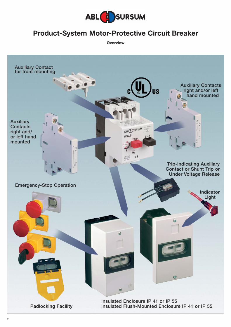
Product-System Motor-Protective Circuit BreakerOverview
2
Auxiliary Contactfor front mounting
AuxiliaryContactsright and/ or left handmounted
Trip-Indicating AuxiliaryContact or Shunt Trip or
Under Voltage Release
IndicatorLight
Insulated Enclosure IP 41 or IP 55Insulated Flush-Mounted Enclosure IP 41 or IP 55
Emergency-Stop Operation
Padlocking Facility
Auxiliary Contactsright and/or left
hand mounted
3
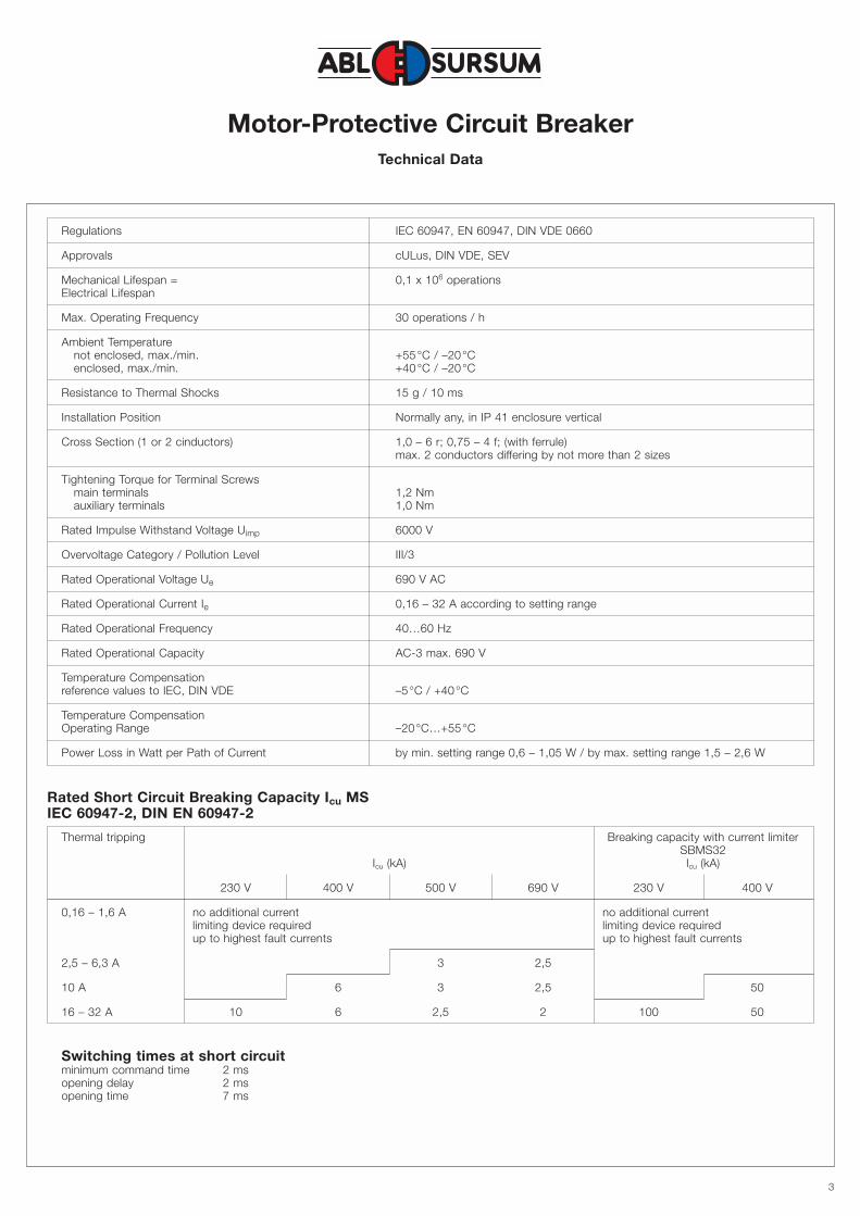
Motor-Protective Circuit BreakerTechnical Data
Regulations IEC 60947, EN 60947, DIN VDE 0660
Approvals cULus, DIN VDE, SEV
Mechanical Lifespan = 0,1 x 10⁶ operationsElectrical Lifespan
Max. Operating Frequency 30 operations / h
Ambient Temperaturenot enclosed, max./min. +55°C / –20°Cenclosed, max./min. +40°C / –20°C
Resistance to Thermal Shocks 15 g / 10 ms
Installation Position Normally any, in IP 41 enclosure vertical
Cross Section (1 or 2 cinductors) 1,0 – 6 r; 0,75 – 4 f; (with ferrule)max. 2 conductors differing by not more than 2 sizes
Tightening Torque for Terminal Screwsmain terminals 1,2 Nmauxiliary terminals 1,0 Nm
Rated Impulse Withstand Voltage Uimp 6000 V
Overvoltage Category / Pollution Level III/3
Rated Operational Voltage Ue 690 V AC
Rated Operational Current Ie 0,16 – 32 A according to setting range
Rated Operational Frequency 40…60 Hz
Rated Operational Capacity AC-3 max. 690 V
Temperature Compensationreference values to IEC, DIN VDE –5°C / +40°C
Temperature CompensationOperating Range –20°C…+55°C
Power Loss in Watt per Path of Current by min. setting range 0,6 – 1,05 W / by max. setting range 1,5 – 2,6 W
Rated Short Circuit Breaking Capacity Icu MSIEC 60947-2, DIN EN 60947-2
Thermal tripping Breaking capacity with current limiterSBMS32
Icu (kA) Icu (kA)
230 V 400 V 500 V 690 V 230 V 400 V
0,16 – 1,6 A no additional current no additional currentlimiting device required limiting device requiredup to highest fault currents up to highest fault currents
2,5 – 6,3 A 3 2,5
10 A 6 3 2,5 50
16 – 32 A 10 6 2,5 2 100 50
Switching times at short circuitminimum command time 2 msopening delay 2 msopening time 7 ms
4
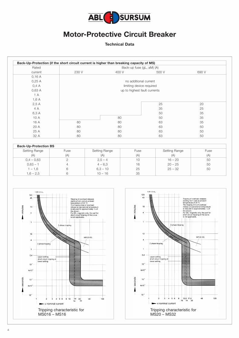
Motor-Protective Circuit BreakerTechnical Data
Back-Up-Protection (if the short circuit current is higher than breaking capacity of MS)Rated Back-up fuse (gL, aM) (A)current 230 V 400 V 500 V 690 V0,16 A0,25 A no additional current0,4 A limiting device required
0,63 A up to highest fault currents1 A
1,6 A2,5 A 25 204 A 35 25
6,3 A 50 3510 A 80 50 3516 A 80 80 63 3520 A 80 80 63 5025 A 80 80 63 5032 A 80 80 63 50
Back-Up-Protection BSSetting Range Fuse Setting Range Fuse Setting Range Fuse
(A) (A) (A) (A) (A) (A)0,4 – 0,63 2 2,5 – 4 10 16 – 20 500,63 – 1 4 4 – 6,3 16 20 – 25 501 – 1,6 6 6,3 – 10 25 25 – 32 50
1,6 – 2,5 6 10 – 16 35
Tripping characteristic forMS016 – MS16
Tripping characteristic forMS20 – MS32
5
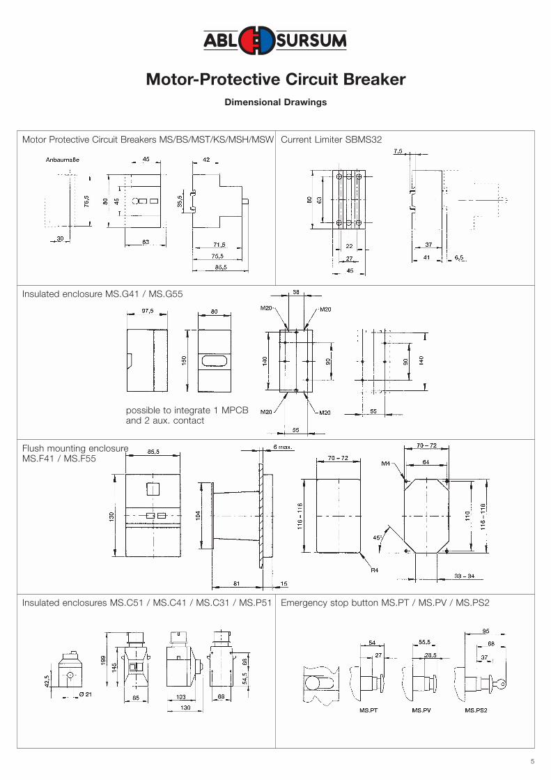
Motor-Protective Circuit BreakerDimensional Drawings
Motor Protective Circuit Breakers MS/BS/MST/KS/MSH/MSW
Insulated enclosure MS.G41 / MS.G55
Flush mounting enclosureMS.F41 / MS.F55
Insulated enclosures MS.C51 / MS.C41 / MS.C31 / MS.P51 Emergency stop button MS.PT / MS.PV / MS.PS2
possible to integrate 1 MPCBand 2 aux. contact
Current Limiter SBMS32
6
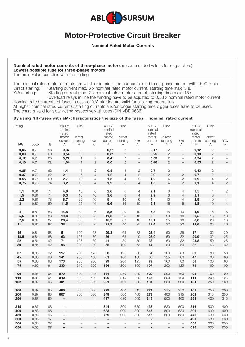
Motor-Protective Circuit BreakerNominal Rated Motor Currents
Nominal rated motor currents of three-phase motors (recommended values for cage rotors)Lowest possible fuse for three-phase motorsThe max. value complies with the setting
The nominal rated motor currents are valid for interior- and surface cooled three-phase motors with 1500 r/min.Direct starting: Starting current max. 6 x nominal rated motor current, starting time max. 5 s.Y/∆ starting: Starting current max. 2 x nominal rated motor current, starting time max. 15 s.
Overload relays in line the winding have to be adjusted to 0,58 x nominal rated motor current.Nominal rated currents of fuses in case of Y/∆ starting are valid for slip-ring motors too.At higher nominal rated currents, starting currents and/or longer starting time bigger fuses have to be used.The chart is valid for slow-acting respectively gl-fuses (DIN VDE 0636).
By using NH-fuses with aM-characteristics the size of the fuses = nominal rated current
Rating 230 V Fuse 400 V Fuse 500 V Fuse 690 V Fusenominal nominal nominal nominal
rated rated rated ratedmotor direct motor direct motor direct motor directcurrent starting Y/∆ current starting Y/∆ current starting Y/∆ current starting Y/∆
kW cosϕ % A A A A A A A A A A A A
0,06 0,7 58 0,37 2 – 0,21 2 – 0,17 2 – 0,12 2 –0,09 0,7 60 0,54 2 – 0,31 2 – 0,25 2 – 0,18 2 –0,12 0,7 60 0,72 4 2 0,41 2 – 0,33 2 – 0,24 2 –0,18 0,7 62 1,04 4 2 0,6 2 – 0,48 2 – 0,35 2 –
0,25 0,7 62 1,4 4 2 0,8 4 2 0,7 2 – 0,43 2 –0,37 0,72 62 2 6 4 1,2 4 2 0,9 2 2 0,7 2 –0,55 0,75 69 2,7 10 4 1,5 4 2 1,2 4 2 0,9 4 20,75 0,78 74 3,2 10 4 1,9 6 4 1,5 4 2 1,1 4 2
1,1 0,81 74 4,6 10 6 2,6 6 4 2,1 6 4 1,5 4 21,5 0,81 74 6,3 16 10 3,6 6 4 2,9 6 4 2,1 6 42,2 0,81 78 8,7 20 10 5 10 6 4 10 4 2,9 10 43 0,82 80 11,5 25 16 6,6 16 10 5,3 16 6 3,8 10 4
4 0,82 83 14,8 32 16 8,5 20 10 6,8 16 10 4,9 16 65,5 0,82 86 19,6 32 25 11,3 25 16 9 20 16 6,5 16 107,5 0,82 87 26,4 50 32 15,2 32 16 12,1 25 16 8,8 20 10
11 0,84 87 38 80 40 21,7 40 25 17,4 32 20 12,6 25 16
15 0,84 88 51 100 63 29,3 63 32 23,4 50 25 17 32 2018,5 0,84 88 63 125 80 36 63 40 28,9 50 32 20,9 32 2522 0,84 92 71 125 80 41 80 50 33 63 32 23,8 50 2530 0,85 92 96 200 100 55 100 63 44 80 50 32 63 32
37 0,86 92 117 200 125 68 125 80 54 100 63 39 80 5045 0,86 93 141 250 160 81 160 100 65 125 80 47 80 6355 0,86 93 173 250 200 99 200 125 79 160 80 58 100 6375 0,86 94 233 315 250 134 200 160 107 200 125 78 160 100
90 0,86 94 279 400 315 161 250 200 129 200 160 93 160 100110 0,86 94 342 500 400 196 315 200 157 250 160 114 200 125132 0,87 95 401 630 500 231 400 250 184 250 200 134 250 160
160 0,87 95 486 630 630 279 400 315 224 315 250 162 250 200200 0,87 95 607 800 630 349 500 400 279 400 315 202 315 250250 0,87 95 – – – 437 630 500 349 500 400 253 400 315
315 0,87 96 – – – 544 800 630 436 630 500 316 500 400400 0,88 96 – – – 683 1000 800 547 800 630 396 630 400450 0,88 96 – – – 769 1000 800 615 800 630 446 630 630500 0,88 97 – – – – – – – – – 491 630 630560 0,88 97 – – – – – – – – – 550 800 630630 0,88 97 – – – – – – – – – 618 800 630
7
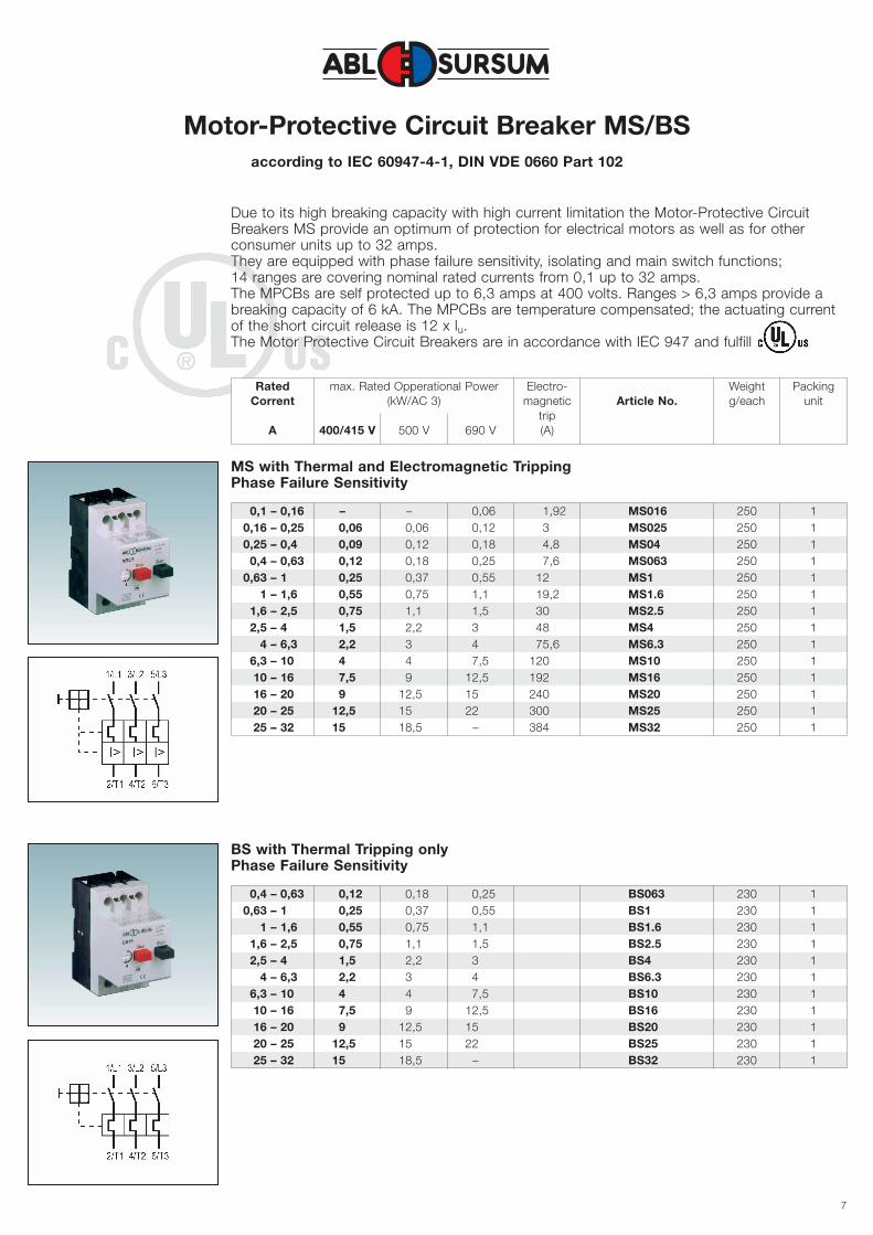
Motor-Protective Circuit Breaker MS/BSaccording to IEC 60947-4-1, DIN VDE 0660 Part 102
Rated max. Rated Opperational Power Electro- Weight PackingCorrent (kW/AC 3) magnetic Article No. g/each unit
tripA 400/415 V 500 V 690 V (A)
Due to its high breaking capacity with high current limitation the Motor-Protective CircuitBreakers MS provide an optimum of protection for electrical motors as well as for otherconsumer units up to 32 amps.They are equipped with phase failure sensitivity, isolating and main switch functions; 14 ranges are covering nominal rated currents from 0,1 up to 32 amps.The MPCBs are self protected up to 6,3 amps at 400 volts. Ranges > 6,3 amps provide abreaking capacity of 6 kA. The MPCBs are temperature compensated; the actuating currentof the short circuit release is 12 x lu.The Motor Protective Circuit Breakers are in accordance with IEC 947 and fulfill
0,1 – 0,16 – – 0,06 1,92 MS016 250 10,16 – 0,25 0,06 0,06 0,12 3 MS025 250 10,25 – 0,4 0,09 0,12 0,18 4,8 MS04 250 1
0,4 – 0,63 0,12 0,18 0,25 7,6 MS063 250 10,63 – 1 0,25 0,37 0,55 12 MS1 250 1
1 – 1,6 0,55 0,75 1,1 19,2 MS1.6 250 11,6 – 2,5 0,75 1,1 1,5 30 MS2.5 250 12,5 – 4 1,5 2,2 3 48 MS4 250 1
4 – 6,3 2,2 3 4 75,6 MS6.3 250 16,3 – 10 4 4 7,5 120 MS10 250 110 – 16 7,5 9 12,5 192 MS16 250 116 – 20 9 12,5 15 240 MS20 250 120 – 25 12,5 15 22 300 MS25 250 125 – 32 15 18,5 – 384 MS32 250 1
MS with Thermal and Electromagnetic TrippingPhase Failure Sensitivity
0,4 – 0,63 0,12 0,18 0,25 BS063 230 10,63 – 1 0,25 0,37 0,55 BS1 230 1
1 – 1,6 0,55 0,75 1,1 BS1.6 230 11,6 – 2,5 0,75 1,1 1,5 BS2.5 230 12,5 – 4 1,5 2,2 3 BS4 230 1
4 – 6,3 2,2 3 4 BS6.3 230 16,3 – 10 4 4 7,5 BS10 230 110 – 16 7,5 9 12,5 BS16 230 116 – 20 9 12,5 15 BS20 230 120 – 25 12,5 15 22 BS25 230 125 – 32 15 18,5 – BS32 230 1
BS with Thermal Tripping onlyPhase Failure Sensitivity
8
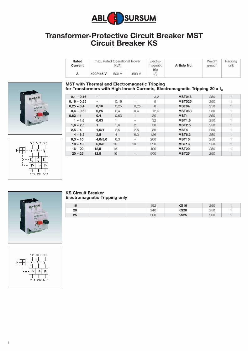
Transformer-Protective Circuit Breaker MSTCircuit Breaker KS
Rated max. Rated Operational Power Electro- Weight PackingCurrent (kVA) magnetic Article No. g/each unit
tripA 400/415 V 500 V 690 V (A)
0,1 – 0,16 – – – 3,2 MST016 250 10,16 – 0,25 – 0,16 – 5 MST025 250 10,25 – 0,4 0,16 0,25 0,25 8 MST04 250 1
0,4 – 0,63 0,25 0,4 0,4 12,6 MST063 250 10,63 – 1 0,4 0,63 1 20 MST1 250 1
1 – 1,6 0,63 1 – 32 MST1.6 250 11,6 – 2,5 1 1,6 2 50 MST2.5 250 12,5 – 4 1,6/1 2,5 2,5 80 MST4 250 1
4 – 6,3 2,5 4 6,3 126 MST6.3 250 16,3 – 10 4,0/5,0 6,3 – 200 MST10 250 110 – 16 6,3/8 10 10 320 MST16 250 116 – 20 12,5 16 – 400 MST20 250 120 – 25 12,5 16 – 500 MST25 250 1
MST with Thermal and Electromagnetic Trippingfor Transformers with High Inrush Currents, Electromagnetic Tripping 20 x Iu
16 192 KS16 250 120 240 KS20 250 125 300 KS25 250 1
KS Circuit BreakerElectromagnetic Tripping only
9
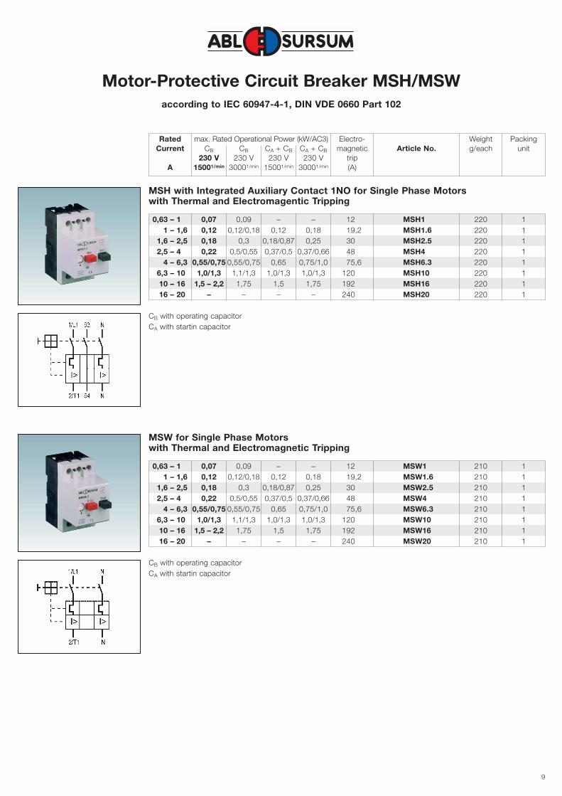
Motor-Protective Circuit Breaker MSH/MSWaccording to IEC 60947-4-1, DIN VDE 0660 Part 102
Rated max. Rated Operational Power (kW/AC3) Electro- Weight PackingCurrent CB CB CA + CB CA + CB magnetic Article No. g/each unit
230 V 230 V 230 V 230 V tripA 15001/min 30001/min 15001/min 30001/min (A)
0,63 – 1 0,07 0,09 – – 12 MSH1 220 11 – 1,6 0,12 0,12/0,18 0,12 0,18 19,2 MSH1.6 220 1
1,6 – 2,5 0,18 0,3 0,18/0,87 0,25 30 MSH2.5 220 12,5 – 4 0,22 0,5/0,55 0,37/0,5 0,37/0,66 48 MSH4 220 1
4 – 6,3 0,55/0,75 0,55/0,75 0,65 0,75/1,0 75,6 MSH6.3 220 16,3 – 10 1,0/1,3 1,1/1,3 1,0/1,3 1,0/1,3 120 MSH10 220 110 – 16 1,5 – 2,2 1,75 1,5 1,75 192 MSH16 220 116 – 20 – – – – 240 MSH20 220 1
MSH with Integrated Auxiliary Contact 1NO for Single Phase Motorswith Thermal and Electromagentic Tripping
0,63 – 1 0,07 0,09 – – 12 MSW1 210 11 – 1,6 0,12 0,12/0,18 0,12 0,18 19,2 MSW1.6 210 1
1,6 – 2,5 0,18 0,3 0,18/0,87 0,25 30 MSW2.5 210 12,5 – 4 0,22 0,5/0,55 0,37/0,5 0,37/0,66 48 MSW4 210 1
4 – 6,3 0,55/0,75 0,55/0,75 0,65 0,75/1,0 75,6 MSW6.3 210 16,3 – 10 1,0/1,3 1,1/1,3 1,0/1,3 1,0/1,3 120 MSW10 210 110 – 16 1,5 – 2,2 1,75 1,5 1,75 192 MSW16 210 116 – 20 – – – – 240 MSW20 210 1
MSW for Single Phase Motorswith Thermal and Electromagnetic Tripping
CB with operating capacitorCA with startin capacitor
CB with operating capacitorCA with startin capacitor
10
Accessories
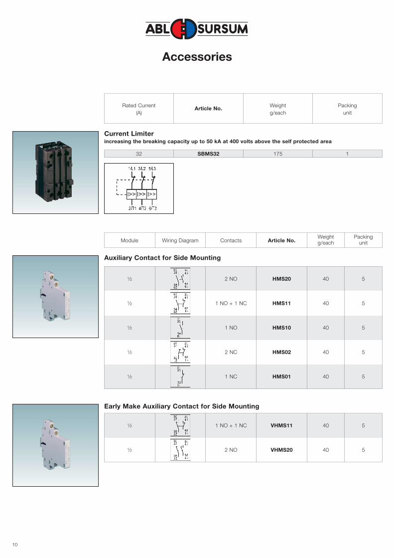
Current Limiterincreasing the breaking capacity up to 50 kA at 400 volts above the self protected area
Auxiliary Contact for Side Mounting
Rated Current Weight Packing(A)
Article No.g/each unit
32 SBMS32 175 1
Module Wiring Diagram Contacts Article No.Weight Packingg/each unit
Early Make Auxiliary Contact for Side Mounting
1⁄2 2 NO HMS20 40 5
1⁄2 1 NO + 1 NC HMS11 40 5
1⁄2 1 NO HMS10 40 5
1⁄2 2 NC HMS02 40 5
1⁄2 1 NC HMS01 40 5
1⁄2 1 NO + 1 NC VHMS11 40 5
1⁄2 2 NO VHMS20 40 5
11
Accessories
Wiring Diagram Contacts Article No.Weight Packingg/each unit
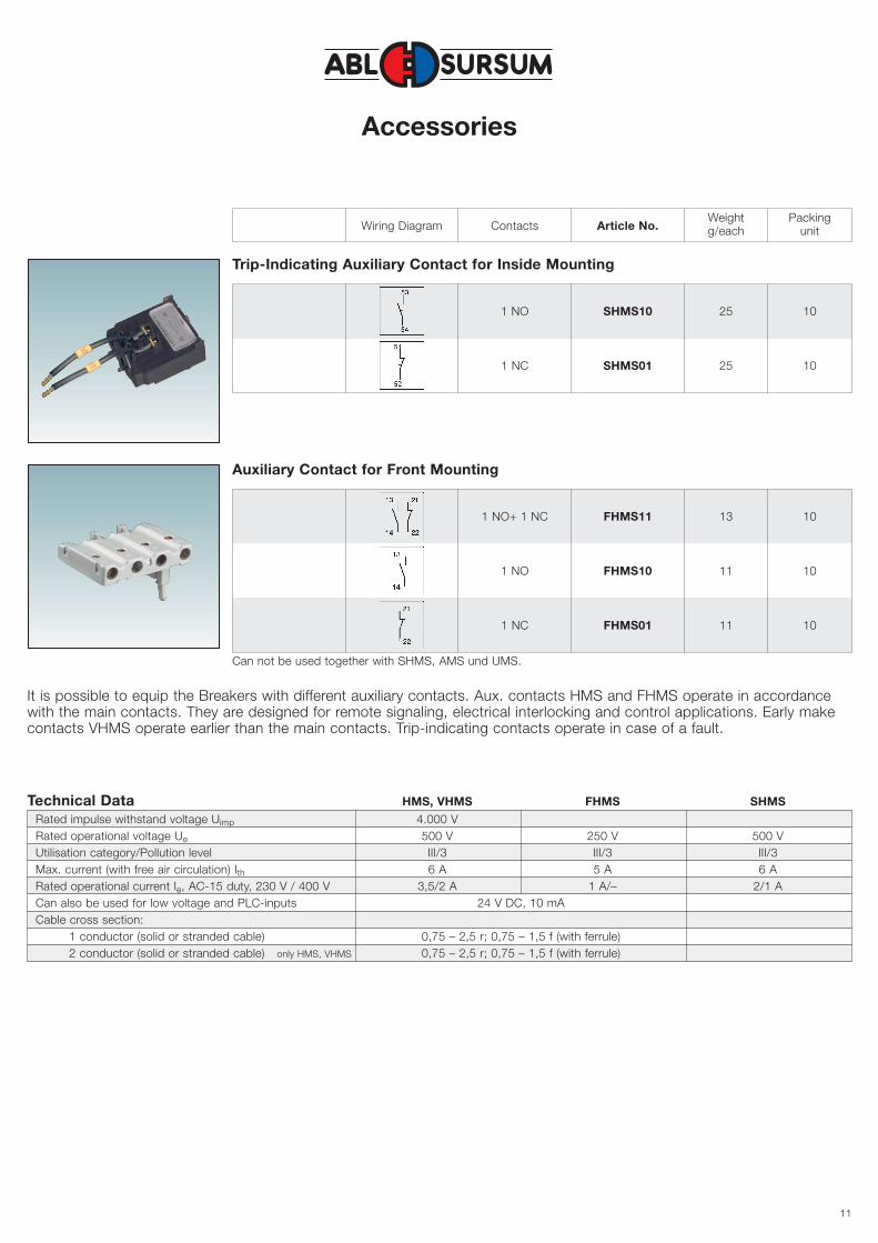
Trip-Indicating Auxiliary Contact for Inside Mounting
1 NO SHMS10 25 10
1 NC SHMS01 25 10
Auxiliary Contact for Front Mounting
1 NO+ 1 NC FHMS11 13 10
1 NO FHMS10 11 10
1 NC FHMS01 11 10
It is possible to equip the Breakers with different auxiliary contacts. Aux. contacts HMS and FHMS operate in accordancewith the main contacts. They are designed for remote signaling, electrical interlocking and control applications. Early makecontacts VHMS operate earlier than the main contacts. Trip-indicating contacts operate in case of a fault.
Technical Data HMS, VHMS FHMS SHMS
Rated impulse withstand voltage Uimp 4.000 VRated operational voltage Ue 500 V 250 V 500 VUtilisation category/Pollution level III/3 III/3 III/3Max. current (with free air circulation) Ith 6 A 5 A 6 ARated operational current Ie, AC-15 duty, 230 V / 400 V 3,5/2 A 1 A/– 2/1 ACan also be used for low voltage and PLC-inputs 24 V DC, 10 mACable cross section:
1 conductor (solid or stranded cable) 0,75 – 2,5 r; 0,75 – 1,5 f (with ferrule)2 conductor (solid or stranded cable) only HMS, VHMS 0,75 – 2,5 r; 0,75 – 1,5 f (with ferrule)
Can not be used together with SHMS, AMS und UMS.
12
Accessories
Rated Operational Weight PackingVoltage (V)
Article No.g/each unit
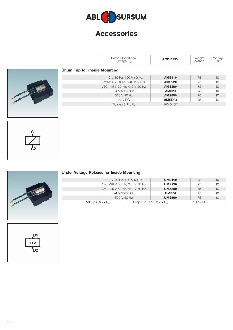
Shunt Trip for Inside Mounting
110 V 50 Hz, 120 V 60 Hz AMS110 75 10220-230V 50 Hz, 240 V 60 Hz AMS220 75 10380-415 V 50 Hz, 440 V 60 Hz AMS380 75 10
24 V 50/60 Hz AMS24 75 10500 V 50 Hz AMS500 75 10
24 V DC AMSD24 75 10Pick up 0,7 x Ue 100 % DF
Under Voltage Release for Inside Mounting
110 V 50 Hz, 120 V 60 Hz UMS110 75 10220-230 V 50 Hz, 240 V 60 Hz UMS220 75 10380-415 V 50 Hz, 440 V 60 Hz UMS380 75 10
24 V 50/60 Hz UMS24 75 10500 V 50 Hz UMS500 75 10
Pick up 0,85 x Ue Drop out 0,35…0,7 x Ue 100% DF
13
Accessories
Nom. Article Weight Packingrated No. g/each unit
current
6 A NMS 35 10
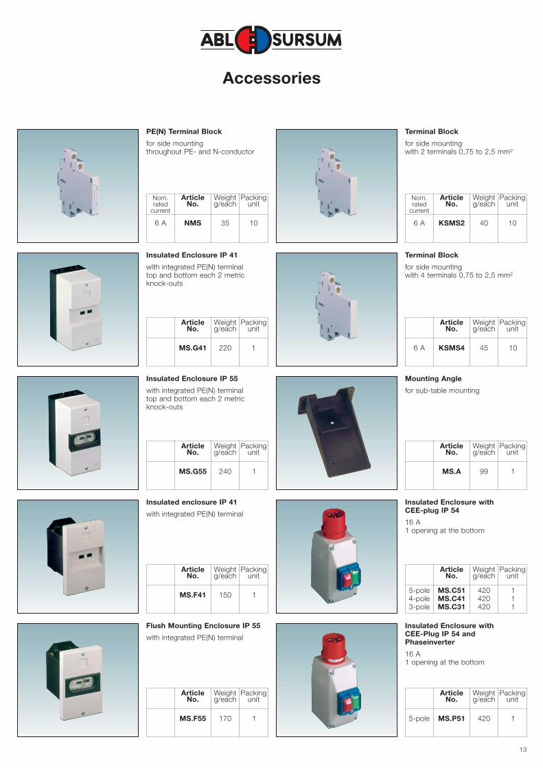
PE(N) Terminal Block
for side mountingthroughout PE- and N-conductor
Nom. Article Weight Packingrated No. g/each unit
current
6 A KSMS2 40 10
Terminal Block
for side mountingwith 2 terminals 0,75 to 2,5 mm2
Article Weight PackingNo. g/each unit
6 A KSMS4 45 10
Terminal Block
for side mountingwith 4 terminals 0,75 to 2,5 mm2
Article Weight PackingNo. g/each unit
MS.G41 220 1
Insulated Enclosure IP 41
with integrated PE(N) terminaltop and bottom each 2 metricknock-outs
Article Weight PackingNo. g/each unit
MS.A 99 1
Mounting Angle
for sub-table mounting
Article Weight PackingNo. g/each unit
MS.G55 240 1
Insulated Enclosure IP 55
with integrated PE(N) terminaltop and bottom each 2 metricknock-outs
Article Weight PackingNo. g/each unit
5-pole MS.C51 420 14-pole MS.C41 420 13-pole MS.C31 420 1
Insulated Enclosure with CEE-plug IP 54
16 A1 opening at the bottom
Article Weight PackingNo. g/each unit
MS.F41 150 1
Insulated enclosure IP 41
with integrated PE(N) terminal
Article Weight PackingNo. g/each unit
5-pole MS.P51 420 1
Insulated Enclosure with CEE-Plug IP 54 andPhaseinverter
16 A1 opening at the bottom
Article Weight PackingNo. g/each unit
MS.F55 170 1
Flush Mounting Enclosure IP 55
with integrated PE(N) terminal
14
Accessories
Article Weight PackingNo. g/pc. unit
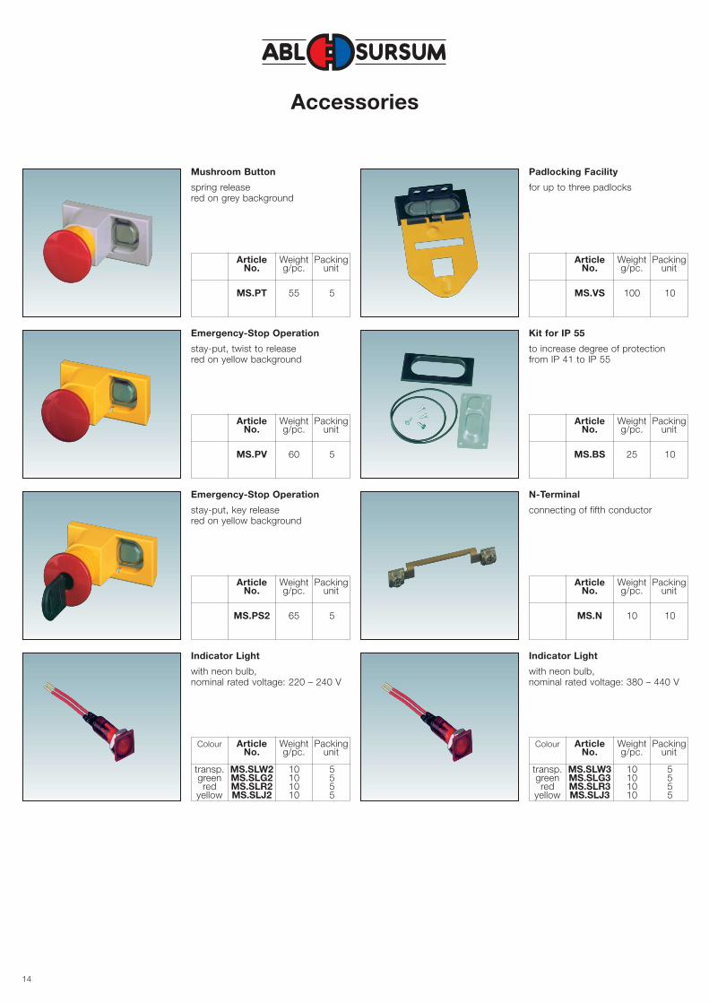
MS.PT 55 5
Mushroom Button
spring releasered on grey background
Article Weight PackingNo. g/pc. unit
MS.VS 100 10
Padlocking Facility
for up to three padlocks
Article Weight PackingNo. g/pc. unit
MS.BS 25 10
Kit for IP 55
to increase degree of protectionfrom IP 41 to IP 55
Article Weight PackingNo. g/pc. unit
MS.PV 60 5
Emergency-Stop Operation
stay-put, twist to releasered on yellow background
Article Weight PackingNo. g/pc. unit
MS.N 10 10
N-Terminal
connecting of fifth conductor
Article Weight PackingNo. g/pc. unit
MS.PS2 65 5
Emergency-Stop Operation
stay-put, key releasered on yellow background
Colour Article Weight PackingNo. g/pc. unit
transp. MS.SLW3 10 5green MS.SLG3 10 5red MS.SLR3 10 5
yellow MS.SLJ3 10 5
Indicator Light
with neon bulb,nominal rated voltage: 380 – 440 V
Colour Article Weight PackingNo. g/pc. unit
transp. MS.SLW2 10 5green MS.SLG2 10 5red MS.SLR2 10 5
yellow MS.SLJ2 10 5
Indicator Light
with neon bulb,nominal rated voltage: 220 – 240 V
15
Accessories
Rated Weight PackingDescription continues lenght Article No. g/pc. unit
current (A)
Rated Weight Packingcontinues Article No. g/pc. unitcurrent (A)
Weight PackingDescription Article No. g/pc. unit
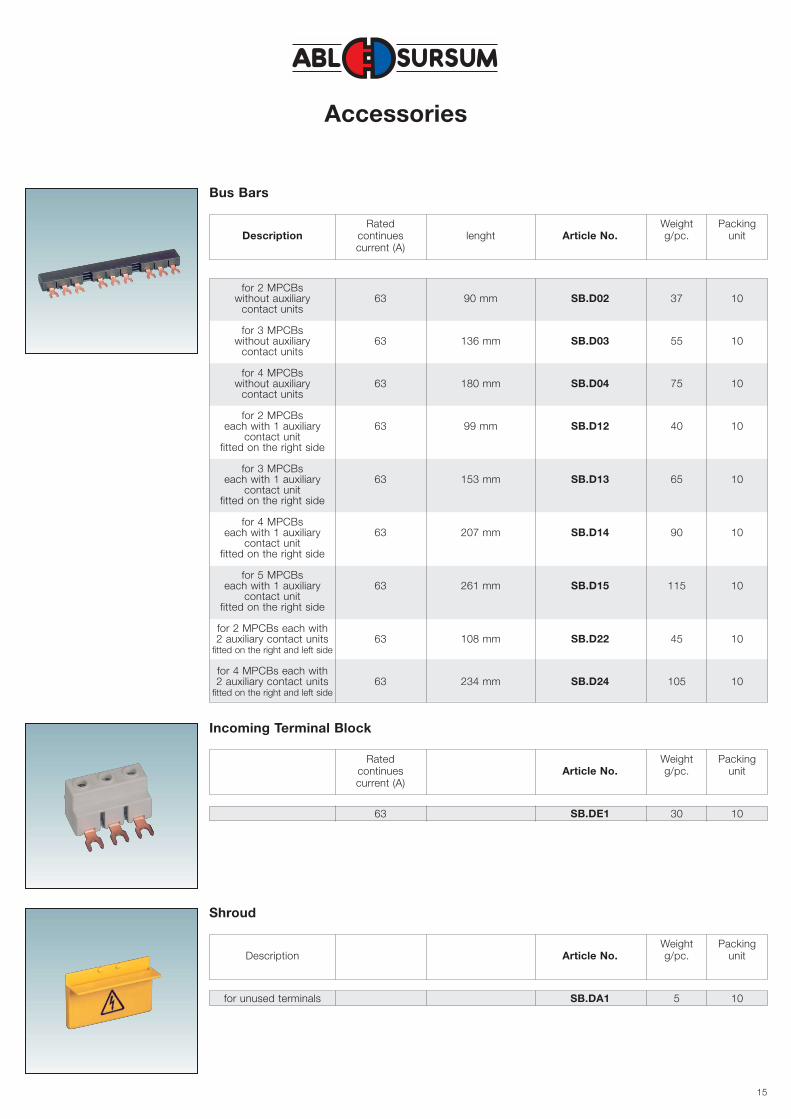
Bus Bars
for 2 MPCBswithout auxiliary 63 90 mm SB.D02 37 10
contact units
for 3 MPCBswithout auxiliary 63 136 mm SB.D03 55 10
contact units
for 4 MPCBswithout auxiliary 63 180 mm SB.D04 75 10
contact units
for 2 MPCBseach with 1 auxiliary 63 99 mm SB.D12 40 10
contact unitfitted on the right side
for 3 MPCBseach with 1 auxiliary 63 153 mm SB.D13 65 10
contact unitfitted on the right side
for 4 MPCBseach with 1 auxiliary 63 207 mm SB.D14 90 10
contact unitfitted on the right side
for 5 MPCBseach with 1 auxiliary 63 261 mm SB.D15 115 10
contact unitfitted on the right side
for 2 MPCBs each with2 auxiliary contact units 63 108 mm SB.D22 45 10
fitted on the right and left side
for 4 MPCBs each with2 auxiliary contact units 63 234 mm SB.D24 105 10
fitted on the right and left side
Incoming Terminal Block
63 SB.DE1 30 10
Shroud
for unused terminals SB.DA1 5 10
ABL SURSUM Bayerische Elektrozubehör GmbH & Co. KGOttensooser Strasse 22 · D-91207 Lauf/Pegnitz · P.O. Box 10 02 47 · D-91192 Lauf/Pegnitz
Phone: +49 (0)9123 188-0 · Fax: +49 (0)9123 188-188 / -189 / -180e-mail: [email protected] · Internet: http://www.abl-sursum.com
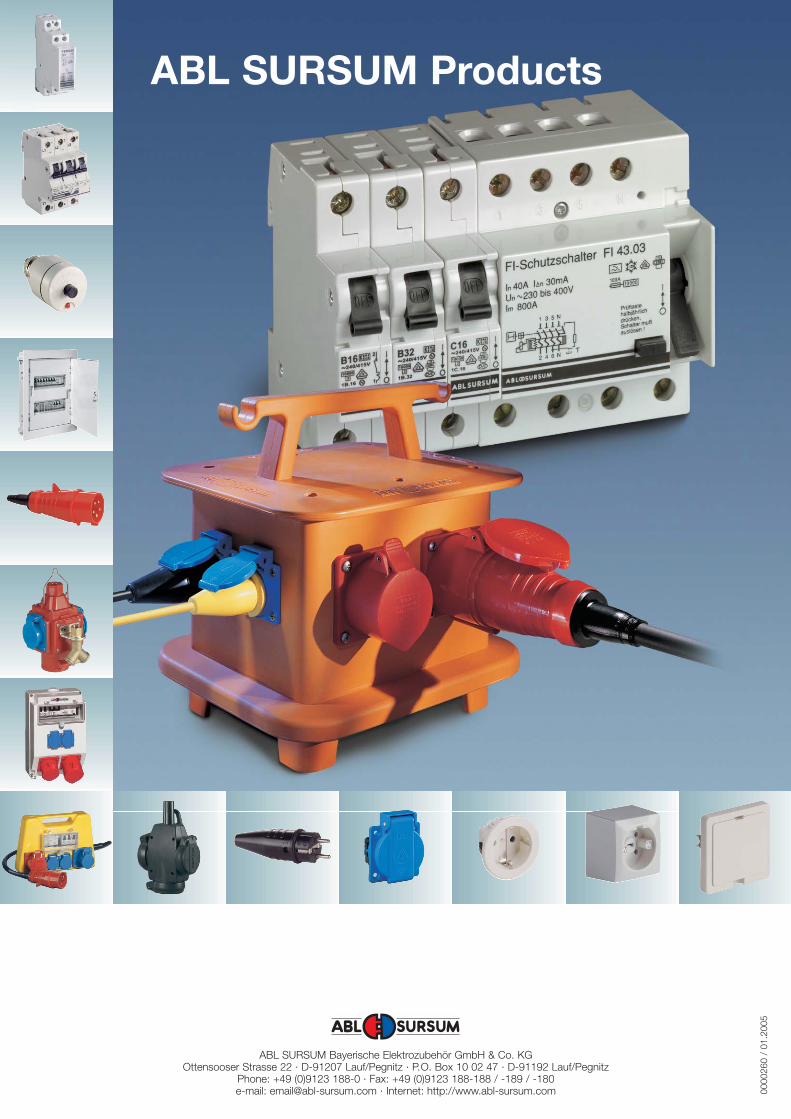
ABL SURSUM Products
0000
260
/ 01
.200
5