Embed Size (px)
Citation preview
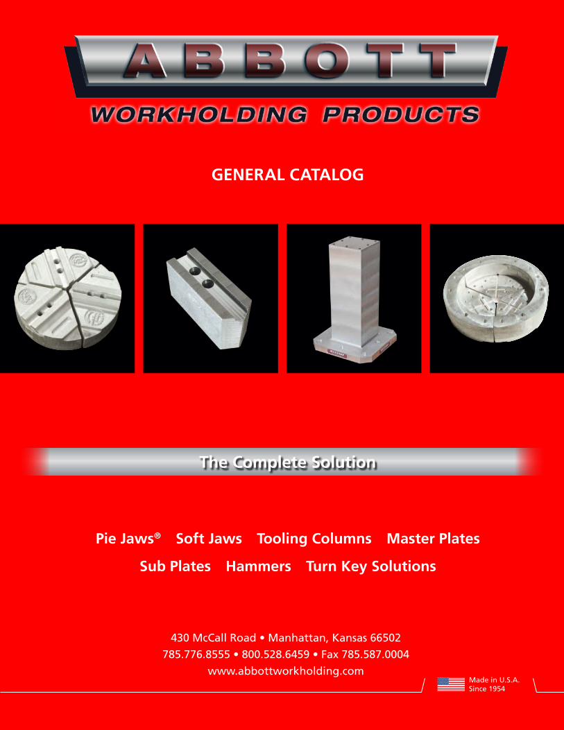
The Complete Solution
430 McCall Road • Manhattan, Kansas 66502
785.776.8555 • 800.528.6459 • Fax 785.587.0004
www.abbottworkholding.com
Pie Jaws® Soft Jaws Tooling Columns Master Plates
Sub Plates Hammers Turn Key Solutions
GeneRAL CATALOG
Made in U.S.A.Since 1954
21-800-528-6459 • Fax 785-587-0004 • www.abbottworkholding.com
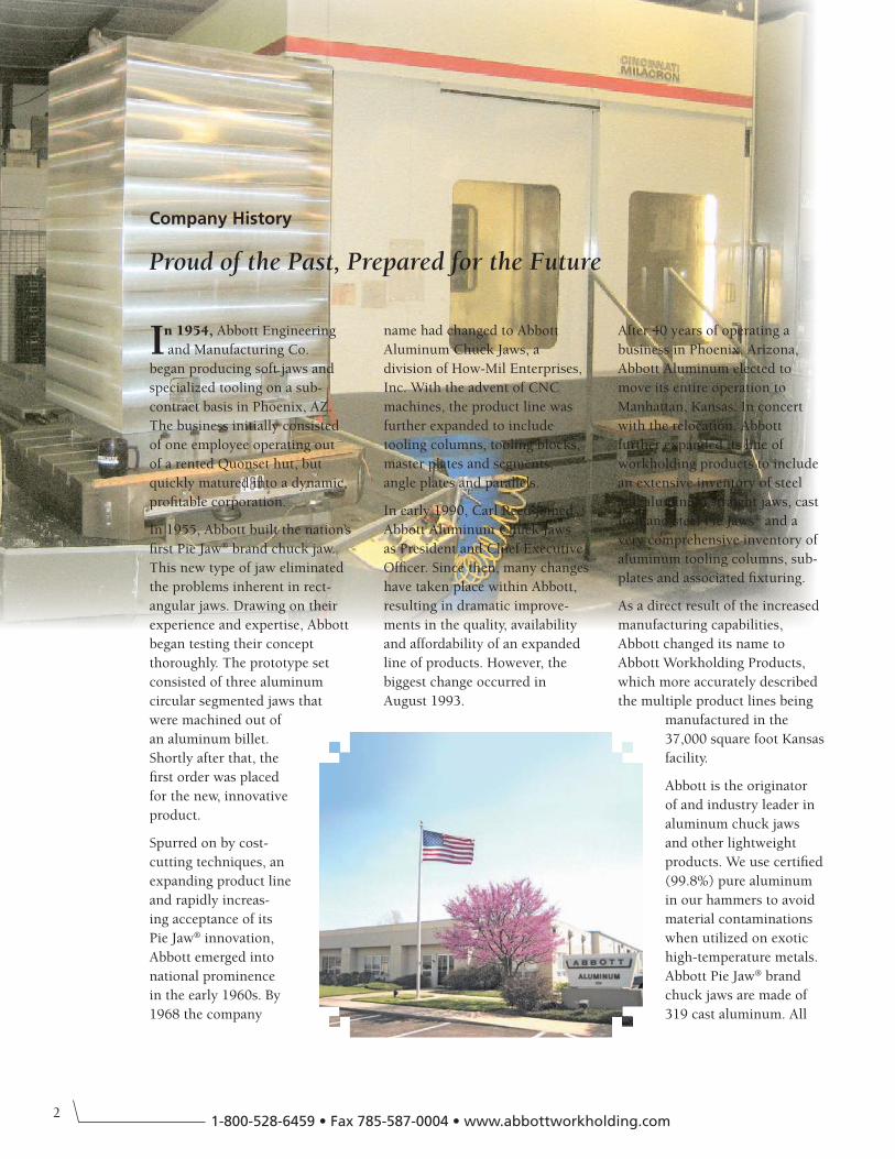
In 1954, Abbott Engineering
and Manufacturing Co.
began producing soft jaws and
specialized tooling on a sub-
contract basis in Phoenix, AZ.
The business initially consisted
of one employee operating out
of a rented Quonset hut, but
quickly matured into a dynamic,
profitable corporation.
In 1955, Abbott built the nation’s
first Pie Jaw® brand chuck jaw.
This new type of jaw eliminated
the problems inherent in rect-
angular jaws. Drawing on their
experience and expertise, Abbott
began testing their concept
thoroughly. The prototype set
consisted of three aluminum
circular segmented jaws that
were machined out of
an aluminum billet.
Shortly after that, the
first order was placed
for the new, innovative
product.
Spurred on by cost-
cutting techniques, an
expanding product line
and rapidly increas-
ing acceptance of its
Pie Jaw® innovation,
Abbott emerged into
national prominence
in the early 1960s. By
1968 the company
name had changed to Abbott
Aluminum Chuck Jaws, a
division of How-Mil Enterprises,
Inc. With the advent of CNC
machines, the product line was
further expanded to include
tooling columns, tooling blocks,
master plates and segments,
angle plates and parallels.
In early 1990, Carl Reed joined
Abbott Aluminum Chuck Jaws
as President and Chief Executive
Officer. Since then, many changes
have taken place within Abbott,
resulting in dramatic improve-
ments in the quality, availability
and affordability of an expanded
line of products. However, the
biggest change occurred in
August 1993.
After 40 years of operating a
business in Phoenix, Arizona,
Abbott Aluminum elected to
move its entire operation to
Manhattan, Kansas. In concert
with the relocation, Abbott
further expanded its line of
workholding products to include
an extensive inventory of steel
and aluminum straight jaws, cast
iron and steel Pie Jaws® and a
very comprehensive inventory of
aluminum tooling columns, sub-
plates and associated fixturing.
As a direct result of the increased
manufacturing capabilities,
Abbott changed its name to
Abbott Workholding Products,
which more accurately described
the multiple product lines being
manufactured in the
37,000 square foot Kansas
facility.
Abbott is the originator
of and industry leader in
aluminum chuck jaws
and other lightweight
products. We use certified
(99.8%) pure aluminum
in our hammers to avoid
material contaminations
when utilized on exotic
high-temperature metals.
Abbott Pie Jaw® brand
chuck jaws are made of
319 cast aluminum. All
Company History
Proud of the Past, Prepared for the Future
3
Pie Jaw® is a registered trademark of Abbott Aluminum Inc.
Tenzaloy™ is a registered trademark of Federated Metals Div., American Smelting and Refining Co.
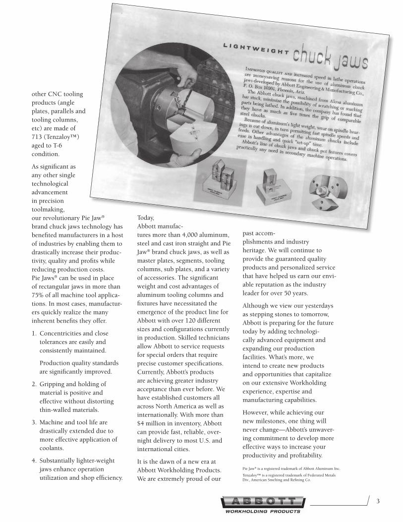
other CNC tooling
products (angle
plates, parallels and
tooling columns,
etc) are made of
713 (Tenzaloy™)
aged to T-6
condition.
As significant as
any other single
technological
advancement
in precision
toolmaking,
our revolutionary Pie Jaw®
brand chuck jaws technology has
benefited manufacturers in a host
of industries by enabling them to
drastically increase their produc-
tivity, quality and profits while
reducing production costs.
Pie Jaws® can be used in place
of rectangular jaws in more than
75% of all machine tool applica-
tions. In most cases, manufactur-
ers quickly realize the many
inherent benefits they offer.
1. Concentricities and close
tolerances are easily and
consistently maintained.
Production quality standards
are significantly improved.
2. Gripping and holding of
material is positive and
effective without distorting
thin-walled materials.
3. Machine and tool life are
drastically extended due to
more effective application of
coolants.
4. Substantially lighter-weight
jaws enhance operation
utilization and shop efficiency.
Today,
Abbott manufac-
tures more than 4,000 aluminum,
steel and cast iron straight and Pie
Jaw® brand chuck jaws, as well as
master plates, segments, tooling
columns, sub plates, and a variety
of accessories. The significant
weight and cost advantages of
aluminum tooling columns and
fixtures have necessitated the
emergence of the product line for
Abbott with over 120 different
sizes and configurations currently
in production. Skilled technicians
allow Abbott to service requests
for special orders that require
precise customer specifications.
Currently, Abbott’s products
are achieving greater industry
acceptance than ever before. We
have established customers all
across North America as well as
internationally. With more than
$4 million in inventory, Abbott
can provide fast, reliable, over-
night delivery to most U.S. and
international cities.
It is the dawn of a new era at
Abbott Workholding Products.
We are extremely proud of our
past accom-
plishments and industry
heritage. We will continue to
provide the guaranteed quality
products and personalized service
that have helped us earn our envi-
able reputation as the industry
leader for over 50 years.
Although we view our yesterdays
as stepping stones to tomorrow,
Abbott is preparing for the future
today by adding technologi-
cally advanced equipment and
expanding our production
facilities. What’s more, we
intend to create new products
and opportunities that capitalize
on our extensive Workholding
experience, expertise and
manufacturing capabilities.
However, while achieving our
new milestones, one thing will
never change—Abbott’s unwaver-
ing commitment to develop more
effective ways to increase your
productivity and profitability.
41-800-528-6459 • Fax 785-587-0004 • www.abbottworkholding.com
Table of Contents
Company History ...................................................... 2-3
Table of Contents ......................................................... 4
Chuck Reference ........................................................... 5
Pie Jaw® Advantages ................................................ 6-7
Chuck Jaws & Jaw Nuts ............................................... 8
1.5mm X 60° Serrated Soft Jaws — Style P ................... 8-9
1.5mm X 60° Serrated Pie Jaws® — Style Q ................. 9-11
1.5mm X 60° Serrated Hard Jaws.................................... 11
1.5mm X 60° Serrated Single Step Hard Jaws ................ 12
Jaw Nuts For 1.5mm X 60° Serrated Chucks ................... 12
3mm X 60° Serrated Soft Jaws — Style H ....................... 12
3mm X 60° Serrated Pie Jaws® — Style S ........................ 13
Jaw Nuts For 3mm X 60° Serrated Chucks ...................... 13
1/16" X 90° Serrated Soft Jaws — Style J ....................... 14
1/16" X 90° Serrated Pie Jaws® — Style K ...................... 15
Jaw Nuts For 1/16" X 90° Serrated Chucks ..................... 16
3/32" X 90° Serrated Soft Jaws — Style J ....................... 16
3/32" X 90° Serrated Pie Jaws® — Style K ...................... 17
Jaw Nuts For 3/32" X 90° Serrated Chucks ..................... 17
American Standard Tongue & Groove Soft Jaws — Style A .............................................................................. 18
American Standard Tongue & Groove Pie Jaws® — Style D ......................................................................... 19-21
American Standard Tongue & Groove Hard Jaws ......... 21
Metric Tongue & Groove Soft Jaws — Style A ............... 22
Metric Tongue & Groove Pie Jaws® — Style D ............... 22
Bullard Style Pie Jaws® — Style W .................................. 23
4 Jaw Bullard Style Pie Jaws® — Style W ........................ 23
Acme Serrated Key Soft Jaws — Style C ......................... 24
Acme Serrated Key Pie Jaws® — Style L ......................... 24
Acme Serrated Key Hard Jaws ........................................ 25
Jaw Nuts For Acme Serrated Key Chucks ...................... 25
Acme Serrated Master Keys ............................................ 25
Square Serrated Key Soft Jaws — Style B ....................... 26
Square Serrated Key Pie Jaws® — Style E ....................... 26
Square Serrated Key Hard Jaws ...................................... 27
Jaw Nuts For Square Serrated Key Chucks .................... 27
Square Serrated Master Keys .......................................... 27
Northfield Air Chuck Soft Jaws — Style R ...................... 28
Northfield Air Chuck Pie Jaws® — Style M ..................... 28
Microcentric Air Chuck Soft Jaws — Style R ................... 29
Microcentric Air Chuck Pie Jaws® — Style M.................. 29
Master Plates .............................................................. 30
Master Plates — Style N .................................................. 30
Segments For Master Plates — Style O ........................... 31
Precision Master Plates ............................................. 32
Precision Master Plates — Style N ................................... 32
Segments For Precision Master Plates — Style O ........... 32
Installation and Application ..................................... 33
Tooling Columns ........................................................ 34
Tenzaloy™ Tooling Columns ........................................... 34
713 (Tenzaloy™) Information ......................................... 35
Square Tooling Columns ................................................. 36
Two-Sided Tooling Columns ............................................ 37
Window Tooling Columns ............................................... 38
Triangle Tooling Columns................................................ 38
Hexagon Tooling Columns .............................................. 38
Octagon Tooling Columns ............................................... 39
Y-Shaped Tooling Columns ............................................. 39
X-Shaped Tooling Columns ............................................. 39
Universal Mount Tooling Columns ........................... 40
Square Configurations .................................................... 40
Two-Sided Configurations ............................................... 40
4th Axis/Indexer Fixturing ........................................ 41
Round Base Tooling Columns ......................................... 41
Sub Plates ................................................................... 42
Aluminum Hammers .................................................. 42
Warranty ..................................................................... 43
5
Chuck Reference
Chuck Jaw Interface Type Style(s) Soft / Pie
ATS 1.5mm x 60° Serrated P/Q
ATLAS Am. Std. Tongue & Groove A/D
AUTOBLOK 1.5mm x 60° Serrated P/Q 1/16" x 90° Serrated J/K 3/32" x 90° Serrated J/K Acme Serrated Key C/L
BISON/ Am. Std. Tongue & Groove A/D BERGMAN
BTC 1.5mm x 60° Serrated P/Q
BUCK Am. Std. Tongue & Groove A/D Square Serrated Key B/E
BULLARD Bullard Style Jaws C/W
CADILLAC Am. Std. Tongue & Groove A/D
CUSHMAN Am. Std. Tongue & Groove A/D Acme Serrated Key C/L
ERICSON 1/16" x 90° Serrated J/K
FORKARDT 1/16" x 90° Serrated J/K 3/32" x 90° Serrated J/K Metric Tongue & Groove A/D
FUJI 3mm x 60° Serrated H/S
GAMET 1/16" x 90° Serrated J/K
GISHOLT Square Serrated Key B/E
HARDINGE 1.5mm x 60° Serrated P/Q 1/16" x 90° Serrated J/K
HOWA 1.5mm x 60° Serrated P/Q 3mm x 60° Serrated H/S 1/16" x 90° Serrated J/K Acme Serrated Key C/L
HURON Am. Std. Tongue & Groove A/D
JAPANESE 1.5mm x 60° Serrated P/Q 3mm x 60° Serrated H/S
KITAGAWA 1.5mm x 60° Serrated P/Q 3mm x 60° Serrated H/S
LOGANSPORT 3mm x 60° Serrated H/S Am. Std. Tongue & Groove A/D Acme Serrated Key C/L Square Serrated Key B/E
Chuck Jaw Interface Type Style(s) Soft / Pie
MATSUMOTO 1.5mm x 60° Serrated P/Q 3mm x 60° Serrated H/S
MICROCENTRIC Microcentric Air Chuck R/M
MMK 1.5mm x 60° Serrated P/Q 3mm x 60° Serrated H/S
NIKKO 1.5 mm x 60° Serrated P/Q
NOBEL Am. Std. Tongue & Groove A/D
NORTHFIELD Northfield Air Chuck R/M
POWERHOLD 1/16" x 90° Serrated J/K
PRATT 1.5mm x 60° Serrated P/Q BURNERD Am. Std. Tongue & Groove A/D Acme Serrated Key C/L
ROHM 1/16" x 90° Serrated J/K Am. Std. Tongue & Groove A/D Metric Tongue & Groove A/D
SCA Am. Std. Tongue & Groove A/D
S-P Am. Std. Tongue & Groove A/D Square Serrated Key B/E
SCHUNK 1.5mm x 60° Serrated P/Q 1/16" x 90° Serrated J/K Metric Tongue & Groove A/D
SEIKI 1.5mm x 60° Serrated P/Q 3mm x 60° Serrated H/S
SKINNER Am. Std. Tongue & Groove A/D
SMW 1.5mm x 60° Serrated P/Q 1/16" x 90° Serrated J/K 3/32" x 90° Serrated J/K Metric Tongue & Groove A/D
STRONG 1.5mm x 60° Serrated P/Q
WARNER/ Am. Std. Tongue & Groove A/D SWASEY Square Serrated Key B/E
YUASA Am. Std. Tongue & Groove A/D
61-800-528-6459 • Fax 785-587-0004 • www.abbottworkholding.com
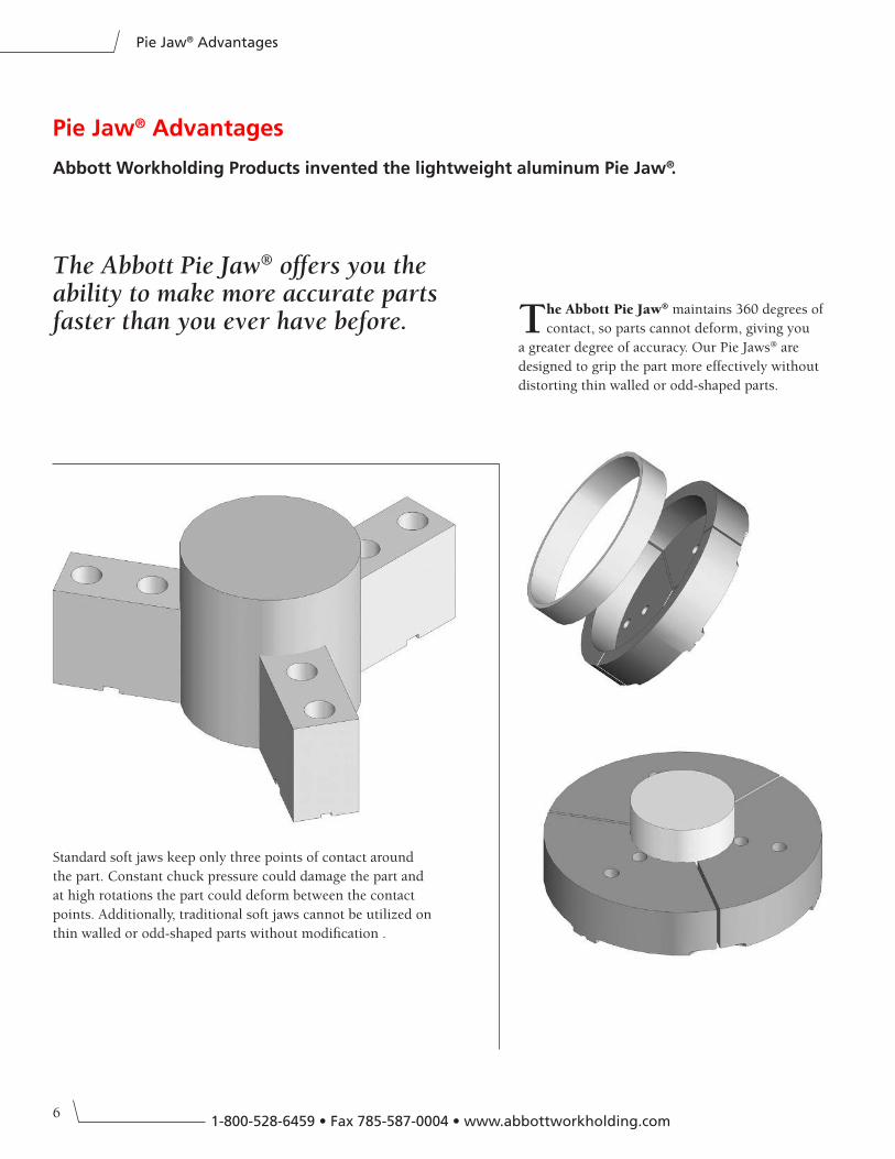
Standard soft jaws keep only three points of contact around
the part. Constant chuck pressure could damage the part and
at high rotations the part could deform between the contact
points. Additionally, traditional soft jaws cannot be utilized on
thin walled or odd-shaped parts without modification .
The Abbott Pie Jaw® maintains 360 degrees of
contact, so parts cannot deform, giving you
a greater degree of accuracy. Our Pie Jaws® are
designed to grip the part more effectively without
distorting thin walled or odd-shaped parts.
Pie Jaw® Advantages
Abbott Workholding Products invented the lightweight aluminum Pie Jaw®.
The Abbott Pie Jaw® offers you the ability to make more accurate parts faster than you ever have before.
Pie Jaw® Advantages
7
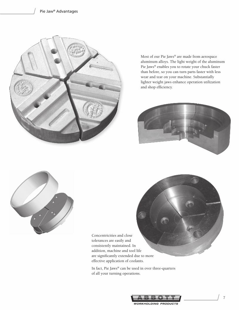
Most of our Pie Jaws® are made from aerospace
aluminum alloys. The light weight of the aluminum
Pie Jaws® enables you to rotate your chuck faster
than before, so you can turn parts faster with less
wear and tear on your machine. Substantially
lighter weight jaws enhance operation utilization
and shop efficiency.
Concentricities and close
tolerances are easily and
consistently maintained. In
addition, machine and tool life
are significantly extended due to more
effective application of coolants.
In fact, Pie Jaws® can be used in over three-quarters
of all your turning operations.
Pie Jaw® Advantages
8
Chuck Jaws & Jaw Nuts
1-800-528-6459 • Fax 785-587-0004 • www.abbottworkholding.com
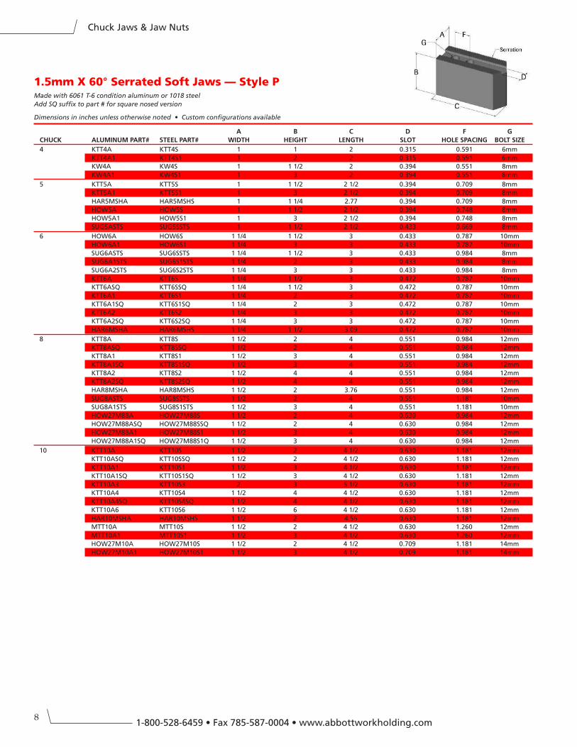
1.5mm X 60° Serrated Soft Jaws — Style PMade with 6061 T-6 condition aluminum or 1018 steel
Add SQ suffix to part # for square nosed version
Dimensions in inches unless otherwise noted • Custom configurations available
A B C D F G
CHUCK ALUMInUM PART# STeeL PART# WIDTH HeIGHT LenGTH SLOT HOLe SPACInG BOLT SIZe
4 KTT4A KTT4S 1 1 2 0.315 0.591 6mm
KTT4A1 KTT4S1 1 2 2 0.315 0.591 6mm
KW4A KW4S 1 1 1/2 2 0.394 0.551 8mm
KW4A1 KW4S1 1 3 2 0.394 0.551 8mm
5 KTT5A KTT5S 1 1 1/2 2 1/2 0.394 0.709 8mm
KTT5A1 KTT5S1 1 3 2 1/2 0.394 0.709 8mm
HAR5MSHA HAR5MSHS 1 1 1/4 2.77 0.394 0.709 8mm
HOW5A HOW5S 1 1 1/2 2 1/2 0.394 0.748 8mm
HOW5A1 HOW5S1 1 3 2 1/2 0.394 0.748 8mm
SUG5ASTS SUG5SSTS 1 1 1/2 2 1/2 0.433 0.669 8mm
6 HOW6A HOW6S 1 1/4 1 1/2 3 0.433 0.787 10mm
HOW6A1 HOW6S1 1 1/4 3 3 0.433 0.787 10mm
SUG6ASTS SUG6SSTS 1 1/4 1 1/2 3 0.433 0.984 8mm
SUG6A1STS SUG6S1STS 1 1/4 2 3 0.433 0.984 8mm
SUG6A2STS SUG6S2STS 1 1/4 3 3 0.433 0.984 8mm
KTT6A KTT6S 1 1/4 1 1/2 3 0.472 0.787 10mm
KTT6ASQ KTT6SSQ 1 1/4 1 1/2 3 0.472 0.787 10mm
KTT6A1 KTT6S1 1 1/4 2 3 0.472 0.787 10mm
KTT6A1SQ KTT6S1SQ 1 1/4 2 3 0.472 0.787 10mm
KTT6A2 KTT6S2 1 1/4 3 3 0.472 0.787 10mm
KTT6A2SQ KTT6S2SQ 1 1/4 3 3 0.472 0.787 10mm
HAR6MSHA HAR6MSHS 1 1/4 1 1/2 3.09 0.472 0.787 10mm
8 KTT8A KTT8S 1 1/2 2 4 0.551 0.984 12mm
KTT8ASQ KTT8SSQ 1 1/2 2 4 0.551 0.984 12mm
KTT8A1 KTT8S1 1 1/2 3 4 0.551 0.984 12mm
KTT8A1SQ KTT8S1SQ 1 1/2 3 4 0.551 0.984 12mm
KTT8A2 KTT8S2 1 1/2 4 4 0.551 0.984 12mm
KTT8A2SQ KTT8S2SQ 1 1/2 4 4 0.551 0.984 12mm
HAR8MSHA HAR8MSHS 1 1/2 2 3.76 0.551 0.984 12mm
SUG8ASTS SUG8SSTS 1 1/2 2 4 0.551 1.181 10mm
SUG8A1STS SUG8S1STS 1 1/2 3 4 0.551 1.181 10mm
HOW27M88A HOW27M88S 1 1/2 2 4 0.630 0.984 12mm
HOW27M88ASQ HOW27M88SSQ 1 1/2 2 4 0.630 0.984 12mm
HOW27M88A1 HOW27M88S1 1 1/2 3 4 0.630 0.984 12mm
HOW27M88A1SQ HOW27M88S1Q 1 1/2 3 4 0.630 0.984 12mm
10 KTT10A KTT10S 1 1/2 2 4 1/2 0.630 1.181 12mm
KTT10ASQ KTT10SSQ 1 1/2 2 4 1/2 0.630 1.181 12mm
KTT10A1 KTT10S1 1 1/2 3 4 1/2 0.630 1.181 12mm
KTT10A1SQ KTT10S1SQ 1 1/2 3 4 1/2 0.630 1.181 12mm
KTT10A3 KTT10S3 2 3 5 1/2 0.630 1.181 12mm
KTT10A4 KTT10S4 1 1/2 4 4 1/2 0.630 1.181 12mm
KTT10A4SQ KTT10S4SQ 1 1/2 4 4 1/2 0.630 1.181 12mm
KTT10A6 KTT10S6 1 1/2 6 4 1/2 0.630 1.181 12mm
HAR10MSHA HAR10MSHS 1 1/2 2 4.56 0.630 1.181 12mm
MTT10A MTT10S 1 1/2 2 4 1/2 0.630 1.260 12mm
MTT10A1 MTT10S1 1 1/2 3 4 1/2 0.630 1.260 12mm
HOW27M10A HOW27M10S 1 1/2 2 4 1/2 0.709 1.181 14mm
HOW27M10A1 HOW27M10S1 1 1/2 3 4 1/2 0.709 1.181 14mm
9
Chuck Jaws & Jaw Nuts
1.5mm X 60° Serrated Soft Jaws — Style P – continued
Made with 6061 T-6 condition aluminum or 1018 steel
Add SQ suffix to part # for square nosed version
Dimensions in inches unless otherwise noted • Custom configurations available
A B C D F G
CHUCK ALUMInUM PART# STeeL PART# WIDTH HeIGHT LenGTH SLOT HOLe SPACInG BOLT SIZe
12 KTT12A KTT12S 2 2 5 1/2 0.709 1.181 14mm
KTT12ASQ KTT12SSQ 2 2 5 1/2 0.709 1.181 14mm
KTT12A1 KTT12S1 2 3 5 1/2 0.709 1.181 14mm
KTT12A1SQ KTT12S1SQ 2 3 5 1/2 0.709 1.181 14mm
KTT12A4 KTT12S4 2 4 5 1/2 0.709 1.181 14mm
KTT12A4SQ KTT12S4SQ 2 4 5 1/2 0.709 1.181 14mm
KTT12A6 KTT12S6 2 6 5 1/2 0.709 1.181 14mm
SEIKI12A SEIKI12S 1 1/2 2 4 1/4 0.709 1.260 14mm
SEIKI12A1 SEIKI12S1 1 1/2 3 4 1/4 0.709 1.260 14mm
SUG12ASTM SUG12SSTM 2 2 5 1/2 0.788 1.378 12mm
KTTB212A KTTB212S 2 2 5 1/2 0.827 1.181 16mm
KTTB212ASQ KTTB212SSQ 2 2 5 1/2 0.827 1.181 16mm
KTTB212A1 KTTB212S1 2 3 5 1/2 0.827 1.181 16mm
KTTB212A1SQ KTTB212S1SQ 2 3 5 1/2 0.827 1.181 16mm
KTTB212A4 KTTB212S4 2 4 5 1/2 0.827 1.181 16mm
KTTB212A4SQ KTTB212S4SQ 2 4 5 1/2 0.827 1.181 16mm
KTTB212A6 KTTB212S6 2 6 5 1/2 0.827 1.181 16mm
HOW27M12A HOW27M12S 2 2 5 1/2 0.827 1.378 16mm
HOW27M12A1 HOW27M12S1 2 3 5 1/2 0.827 1.378 16mm
14 SUG14ASTG SUG14SSTG 2 3 6 5/16 0.827 1.772 16mm
15-18 KTT15A KTT15S 2 1/2 3 6 1/2 0.866 1.693 20mm
KTT15ASQ KTT15SSQ 2 1/2 3 6 1/2 0.866 1.693 20mm
KTT15A1 KTT15S1 2 1/2 4 6 1/2 0.866 1.693 20mm
KTT15A1SQ KTT15S1SQ 2 1/2 4 6 1/2 0.866 1.693 20mm
KTT15A6 KTT15S6 2 1/2 6 6 1/2 0.866 1.693 20mm
KTTB215A KTTB215S 2 1/2 3 6 1/2 1.004 1.693 20mm
KTTB215ASQ KTTB215SSQ 2 1/2 3 6 1/2 1.004 1.693 20mm
KTTB215A1 KTTB215S1 2 1/2 4 6 1/2 1.004 1.693 20mm
KTTB215A1SQ KTTB215S1SQ 2 1/2 4 6 1/2 1.004 1.693 20mm
KTTB215A6 KTTB215S6 2 1/2 6 6 1/2 1.004 1.693 20mm
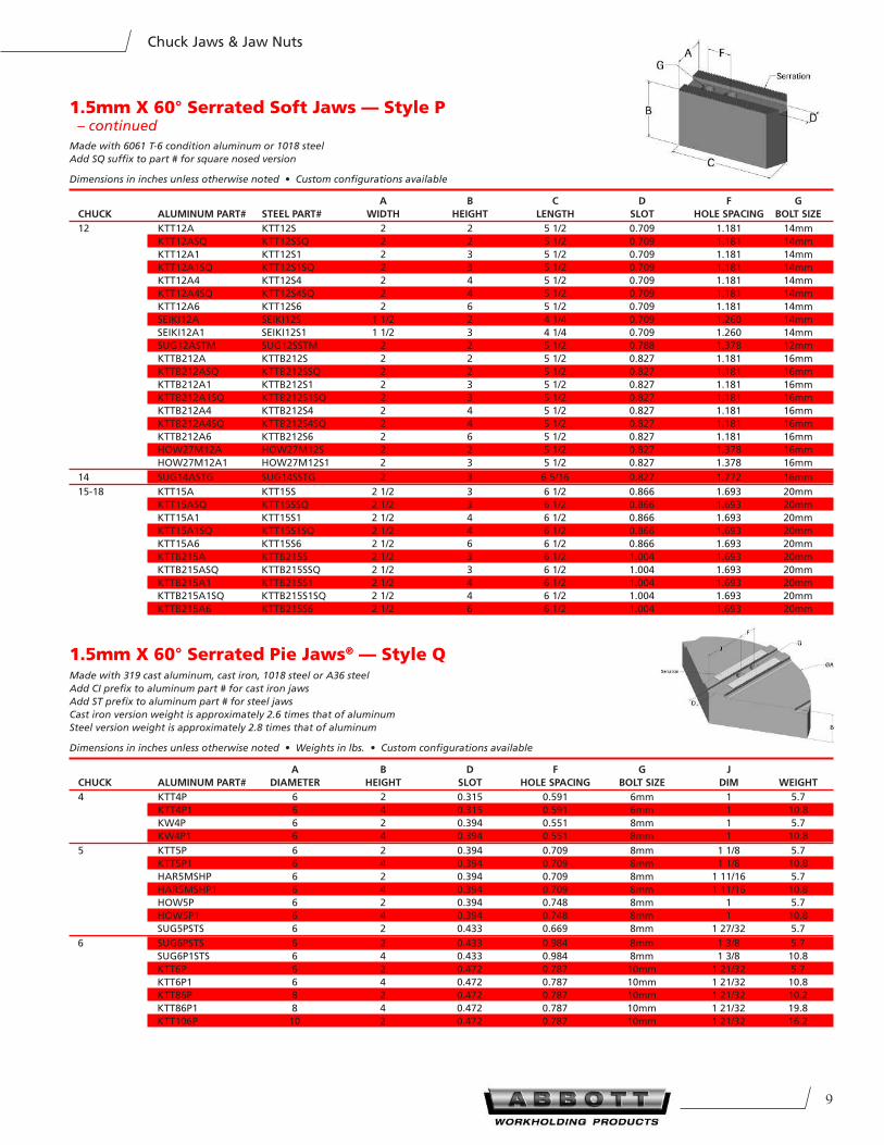
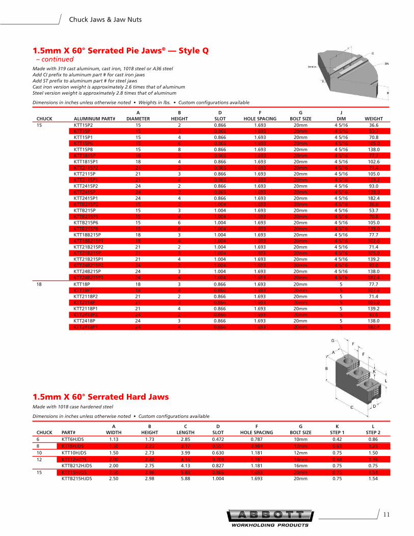
1.5mm X 60° Serrated Pie Jaws® — Style QMade with 319 cast aluminum, cast iron, 1018 steel or A36 steel
Add CI prefix to aluminum part # for cast iron jaws
Add ST prefix to aluminum part # for steel jaws
Cast iron version weight is approximately 2.6 times that of aluminum
Steel version weight is approximately 2.8 times that of aluminum
Dimensions in inches unless otherwise noted • Weights in lbs. • Custom configurations available
A B D F G J
CHUCK ALUMInUM PART# DIAMeTeR HeIGHT SLOT HOLe SPACInG BOLT SIZe DIM WeIGHT
4 KTT4P 6 2 0.315 0.591 6mm 1 5.7
KTT4P1 6 4 0.315 0.591 6mm 1 10.8
KW4P 6 2 0.394 0.551 8mm 1 5.7
KW4P1 6 4 0.394 0.551 8mm 1 10.8
5 KTT5P 6 2 0.394 0.709 8mm 1 1/8 5.7
KTT5P1 6 4 0.394 0.709 8mm 1 1/8 10.8
HAR5MSHP 6 2 0.394 0.709 8mm 1 11/16 5.7
HAR5MSHP1 6 4 0.394 0.709 8mm 1 11/16 10.8
HOW5P 6 2 0.394 0.748 8mm 1 5.7
HOW5P1 6 4 0.394 0.748 8mm 1 10.8
SUG5PSTS 6 2 0.433 0.669 8mm 1 27/32 5.7
6 SUG6PSTS 6 2 0.433 0.984 8mm 1 3/8 5.7
SUG6P1STS 6 4 0.433 0.984 8mm 1 3/8 10.8
KTT6P 6 2 0.472 0.787 10mm 1 21/32 5.7
KTT6P1 6 4 0.472 0.787 10mm 1 21/32 10.8
KTT86P 8 2 0.472 0.787 10mm 1 21/32 10.2
KTT86P1 8 4 0.472 0.787 10mm 1 21/32 19.8
KTT106P 10 2 0.472 0.787 10mm 1 21/32 16.2
101-800-528-6459 • Fax 785-587-0004 • www.abbottworkholding.com
Chuck Jaws & Jaw Nuts
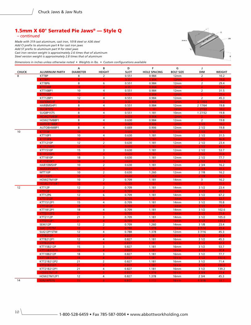
1.5mm X 60° Serrated Pie Jaws® — Style Q – continued
Made with 319 cast aluminum, cast iron, 1018 steel or A36 steel
Add CI prefix to aluminum part # for cast iron jaws
Add ST prefix to aluminum part # for steel jaws
Cast iron version weight is approximately 2.6 times that of aluminum
Steel version weight is approximately 2.8 times that of aluminum
Dimensions in inches unless otherwise noted • Weights in lbs. • Custom configurations available
A B D F G J
CHUCK ALUMInUM PART# DIAMeTeR HeIGHT SLOT HOLe SPACInG BOLT SIZe DIM WeIGHT
8 KTT8P 8 2 0.551 0.984 12mm 2 10.2
KTT8P1 8 4 0.551 0.984 12mm 2 19.8
KTT8P6 8 6 0.551 0.984 12mm 2 29.4
KTT108P 10 2 0.551 0.984 12mm 2 16.2
KTT108P1 10 4 0.551 0.984 12mm 2 31.5
KTT128P 12 2 0.551 0.984 12mm 2 23.4
KTT128P1 12 4 0.551 0.984 12mm 2 45.3
HAR8MSHP 8 2 0.551 0.984 12mm 2 17/64 10.2
HAR8MSHP1 8 4 0.551 0.984 12mm 2 17/64 19.8
SUG8PSTS 8 2 0.551 1.181 10mm 1 27/32 10.2
SUG8P1STS 8 4 0.551 1.181 10mm 1 27/32 19.8
HOW27M88P 8 2 0.630 0.984 12mm 2 10.2
HOW27M88P1 8 4 0.630 0.984 12mm 2 19.8
AUTOBHM8P 8 2 0.669 0.906 12mm 2 1/2 10.2
AUTOBHM8P1 8 4 0.669 0.906 12mm 2 1/2 19.8
10 KTT10P 10 2 0.630 1.181 12mm 2 1/2 16.2
KTT10P1 10 4 0.630 1.181 12mm 2 1/2 31.5
KTT10P6 10 6 0.630 1.181 12mm 2 1/2 46.8
KTT1210P 12 2 0.630 1.181 12mm 2 1/2 23.4
KTT1210P1 12 4 0.630 1.181 12mm 2 1/2 45.3
KTT1510P 15 3 0.630 1.181 12mm 2 1/2 53.7
KTT1510P1 15 4 0.630 1.181 12mm 2 1/2 70.8
KTT1810P 18 3 0.630 1.181 12mm 2 1/2 77.7
KTT1810P1 18 4 0.630 1.181 12mm 2 1/2 102.6
HAR10MSHP 10 2 0.630 1.181 12mm 2 3/4 16.2
HAR10MSHP1 10 4 0.630 1.181 12mm 2 3/4 31.5
MTT10P 10 2 0.630 1.260 12mm 2 7/8 16.2
MTT10P1 10 4 0.630 1.260 12mm 2 7/8 31.5
HOW27M10P 10 2 0.709 1.181 14mm 3 16.2
HOW27M10P1 10 4 0.709 1.181 14mm 3 31.5
12 KTT12P 12 2 0.709 1.181 14mm 3 1/2 23.4
KTT12P1 12 4 0.709 1.181 14mm 3 1/2 45.3
KTT12P6 12 6 0.709 1.181 14mm 3 1/2 67.2
KTT1512P 15 3 0.709 1.181 14mm 3 1/2 53.7
KTT1512P1 15 4 0.709 1.181 14mm 3 1/2 70.8
KTT1812P 18 3 0.709 1.181 14mm 3 1/2 77.7
KTT1812P1 18 4 0.709 1.181 14mm 3 1/2 102.6
KTT2112P2 21 2 0.709 1.181 14mm 3 1/2 71.4
KTT2112P 21 3 0.709 1.181 14mm 3 1/2 105.0
KTT2112P1 21 4 0.709 1.181 14mm 3 1/2 139.2
SEIKI12P 12 2 0.709 1.260 14mm 3 1/8 23.4
SUG12PSTM 12 2 0.788 1.378 12mm 3 7/16 23.4
SUG12P1STM 12 4 0.788 1.378 12mm 3 7/16 45.3
KTTB212P 12 2 0.827 1.181 16mm 3 1/2 23.4
KTTB212P1 12 4 0.827 1.181 16mm 3 1/2 45.3
KTTB212P6 12 6 0.827 1.181 16mm 3 1/2 67.2
KTT15B212P 15 3 0.827 1.181 16mm 3 1/2 53.7
KTT15B212P1 15 4 0.827 1.181 16mm 3 1/2 70.8
KTT18B212P 18 3 0.827 1.181 16mm 3 1/2 77.7
KTT18B212P1 18 4 0.827 1.181 16mm 3 1/2 102.6
KTT21B212P2 21 2 0.827 1.181 16mm 3 1/2 71.4
KTT21B212P 21 3 0.827 1.181 16mm 3 1/2 105.0
KTT21B212P1 21 4 0.827 1.181 16mm 3 1/2 139.2
HOW27M12P 12 2 0.827 1.378 16mm 2 3/4 23.4
HOW27M12P1 12 4 0.827 1.378 16mm 2 3/4 45.3
14 SUG14PSTG 15 3 0.827 1.772 16mm 4 3/16 53.7
11
Chuck Jaws & Jaw Nuts
1.5mm X 60° Serrated Pie Jaws® — Style Q – continued
Made with 319 cast aluminum, cast iron, 1018 steel or A36 steel
Add CI prefix to aluminum part # for cast iron jaws
Add ST prefix to aluminum part # for steel jaws
Cast iron version weight is approximately 2.6 times that of aluminum
Steel version weight is approximately 2.8 times that of aluminum
Dimensions in inches unless otherwise noted • Weights in lbs. • Custom configurations available
A B D F G J
CHUCK ALUMInUM PART# DIAMeTeR HeIGHT SLOT HOLe SPACInG BOLT SIZe DIM WeIGHT
15 KTT15P2 15 2 0.866 1.693 20mm 4 5/16 36.6
KTT15P 15 3 0.866 1.693 20mm 4 5/16 53.7
KTT15P1 15 4 0.866 1.693 20mm 4 5/16 70.8
KTT15P6 15 6 0.866 1.693 20mm 4 5/16 105.0
KTT15P8 15 8 0.866 1.693 20mm 4 5/16 138.0
KTT1815P 18 3 0.866 1.693 20mm 4 5/16 77.7
KTT1815P1 18 4 0.866 1.693 20mm 4 5/16 102.6
KTT2115P2 21 2 0.866 1.693 20mm 4 5/16 71.4
KTT2115P 21 3 0.866 1.693 20mm 4 5/16 105.0
KTT2115P1 21 4 0.866 1.693 20mm 4 5/16 139.2
KTT2415P2 24 2 0.866 1.693 20mm 4 5/16 93.0
KTT2415P 24 3 0.866 1.693 20mm 4 5/16 138.0
KTT2415P1 24 4 0.866 1.693 20mm 4 5/16 182.4
KTTB215P2 15 2 1.004 1.693 20mm 4 5/16 36.6
KTTB215P 15 3 1.004 1.693 20mm 4 5/16 53.7
KTTB215P1 15 4 1.004 1.693 20mm 4 5/16 70.8
KTTB215P6 15 6 1.004 1.693 20mm 4 5/16 105.0
KTTB215P8 15 8 1.004 1.693 20mm 4 5/16 138.0
KTT18B215P 18 3 1.004 1.693 20mm 4 5/16 77.7
KTT18B215P1 18 4 1.004 1.693 20mm 4 5/16 102.6
KTT21B215P2 21 2 1.004 1.693 20mm 4 5/16 71.4
KTT21B215P 21 3 1.004 1.693 20mm 4 5/16 105.0
KTT21B215P1 21 4 1.004 1.693 20mm 4 5/16 139.2
KTT24B215P2 24 2 1.004 1.693 20mm 4 5/16 93.0
KTT24B215P 24 3 1.004 1.693 20mm 4 5/16 138.0
KTT24B215P1 24 4 1.004 1.693 20mm 4 5/16 182.4
18 KTT18P 18 3 0.866 1.693 20mm 5 77.7
KTT18P1 18 4 0.866 1.693 20mm 5 102.6
KTT2118P2 21 2 0.866 1.693 20mm 5 71.4
KTT2118P 21 3 0.866 1.693 20mm 5 105.0
KTT2118P1 21 4 0.866 1.693 20mm 5 139.2
KTT2418P2 24 2 0.866 1.693 20mm 5 93.0
KTT2418P 24 3 0.866 1.693 20mm 5 138.0
KTT2418P1 24 4 0.866 1.693 20mm 5 182.4
1.5mm X 60° Serrated Hard JawsMade with 1018 case hardened steel
Dimensions in inches unless otherwise noted • Custom configurations available
A B C D F G K L
CHUCK PART# WIDTH HeIGHT LenGTH SLOT HOLe SPACInG BOLT SIZe STeP 1 STeP 2
6 KTT6HJDS 1.13 1.73 2.85 0.472 0.787 10mm 0.42 0.86
8 KTT8HJDS 1.50 2.23 3.17 0.551 0.984 12mm 0.63 1.25
10 KTT10HJDS 1.50 2.73 3.99 0.630 1.181 12mm 0.75 1.50
12 KTT12HJDS 2.00 2.48 4.16 0.709 1.181 14mm 0.68 1.36
KTTB212HJDS 2.00 2.75 4.13 0.827 1.181 16mm 0.75 0.75
15 KTT15HJDS 2.50 2.98 5.88 0.866 1.693 20mm 0.75 1.54
KTTB215HJDS 2.50 2.98 5.88 1.004 1.693 20mm 0.75 1.54
121-800-528-6459 • Fax 785-587-0004 • www.abbottworkholding.com
Chuck Jaws & Jaw Nuts
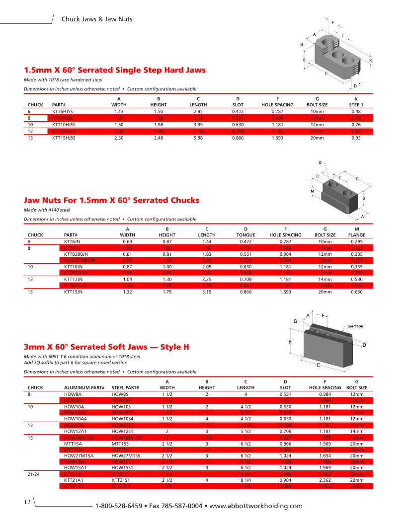
Jaw Nuts For 1.5mm X 60° Serrated ChucksMade with 4140 steel
Dimensions in inches unless otherwise noted • Custom configurations available
A B C D F G M
CHUCK PART# WIDTH HeIGHT LenGTH TOnGUe HOLe SPACInG BOLT SIZe FLAnGe
6 KTT6JN 0.69 0.87 1.44 0.472 0.787 10mm 0.295
8 KTT8JN 0.80 1.00 1.87 0.551 0.984 12mm 0.335
KTTB208JN 0.81 0.81 1.83 0.551 0.984 12mm 0.335
HOW27M88JN 0.98 1.00 2.00 0.630 0.984 12mm 0.375
10 KTT10JN 0.87 1.00 2.05 0.630 1.181 12mm 0.335
KTTB210JN 0.89 0.85 2.01 0.630 1.181 12mm 0.335
12 KTT12JN 1.04 1.30 2.25 0.709 1.181 14mm 0.530
KTTB212JN 1.16 1.09 2.19 0.827 1.181 16mm 0.450
15 KTT15JN 1.32 1.79 3.15 0.866 1.693 20mm 0.650
1.5mm X 60° Serrated Single Step Hard JawsMade with 1018 case hardened steel
Dimensions in inches unless otherwise noted • Custom configurations available
A B C D F G K
CHUCK PART# WIDTH HeIGHT LenGTH SLOT HOLe SPACInG BOLT SIZe STeP 1
6 KTT6HJSS 1.13 1.50 2.85 0.472 0.787 10mm 0.48
8 KTT8HJSS 1.50 1.98 3.16 0.551 0.984 12mm 0.75
10 KTT10HJSS 1.50 1.98 3.99 0.630 1.181 12mm 0.76
12 KTT12HJSS 2.00 1.98 4.16 0.709 1.181 14mm 0.83
15 KTT15HJSS 2.50 2.48 5.88 0.866 1.693 20mm 0.93
3mm X 60° Serrated Soft Jaws — Style HMade with 6061 T-6 condition aluminum or 1018 steel
Add SQ suffix to part # for square nosed version
Dimensions in inches unless otherwise noted • Custom configurations available
A B C D F G
CHUCK ALUMInUM PART# STeeL PART# WIDTH HeIGHT LenGTH SLOT HOLe SPACInG BOLT SIZe
8 HOW8A HOW8S 1 1/2 2 4 0.551 0.984 12mm
HOW8A1 HOW8S1 1 1/2 3 4 0.551 0.984 12mm
10 HOW10A HOW10S 1 1/2 2 4 1/2 0.630 1.181 12mm
HOW10A1 HOW10S1 1 1/2 3 4 1/2 0.630 1.181 12mm
HOW10A4 HOW10S4 1 1/2 4 4 1/2 0.630 1.181 12mm
12 HOW12A HOW12S 2 2 5 1/2 0.709 1.181 14mm
HOW12A1 HOW12S1 2 3 5 1/2 0.709 1.181 14mm
15 HOW7MA15A HOW7MA15S 2 2 1/2 5 0.827 1.575 16mm
MTT15A MTT15S 2 1/2 3 6 1/2 0.866 1.969 20mm
MTT15A1 MTT15S1 2 1/2 4 6 1/2 0.866 1.969 20mm
HOW27M15A HOW27M15S 2 1/2 3 6 1/2 1.024 1.654 20mm
HOW15A HOW15S 2 1/2 3 6 1/2 1.024 1.969 20mm
HOW15A1 HOW15S1 2 1/2 4 6 1/2 1.024 1.969 20mm
21-24 KTT21A KTT21S 2 1/2 3 8 1/4 0.984 2.362 20mm
KTT21A1 KTT21S1 2 1/2 4 8 1/4 0.984 2.362 20mm
KTT21A5 KTT21S5 2 1/2 5 8 1/4 0.984 2.362 20mm
13
Chuck Jaws & Jaw Nuts
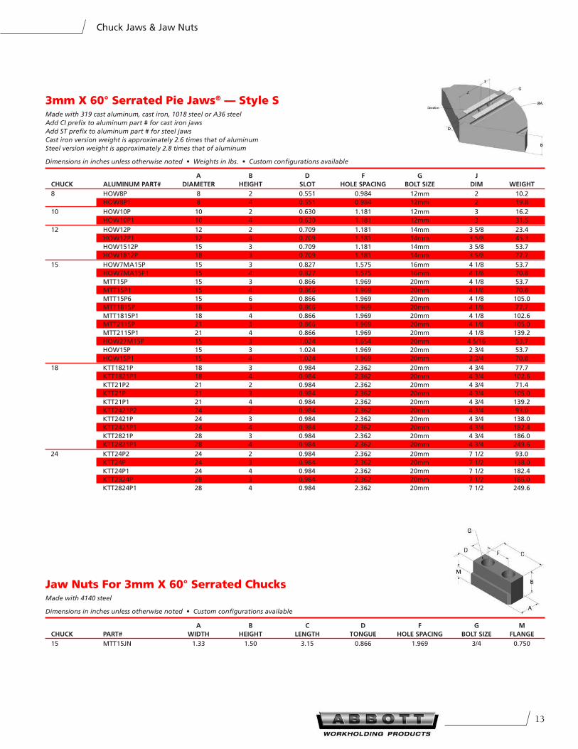
3mm X 60° Serrated Pie Jaws® — Style SMade with 319 cast aluminum, cast iron, 1018 steel or A36 steel
Add CI prefix to aluminum part # for cast iron jaws
Add ST prefix to aluminum part # for steel jaws
Cast iron version weight is approximately 2.6 times that of aluminum
Steel version weight is approximately 2.8 times that of aluminum
Dimensions in inches unless otherwise noted • Weights in lbs. • Custom configurations available
A B D F G J
CHUCK ALUMInUM PART# DIAMeTeR HeIGHT SLOT HOLe SPACInG BOLT SIZe DIM WeIGHT
8 HOW8P 8 2 0.551 0.984 12mm 2 10.2
HOW8P1 8 4 0.551 0.984 12mm 2 19.8
10 HOW10P 10 2 0.630 1.181 12mm 3 16.2
HOW10P1 10 4 0.630 1.181 12mm 3 31.5
12 HOW12P 12 2 0.709 1.181 14mm 3 5/8 23.4
HOW12P1 12 4 0.709 1.181 14mm 3 5/8 45.3
HOW1512P 15 3 0.709 1.181 14mm 3 5/8 53.7
HOW1812P 18 3 0.709 1.181 14mm 3 5/8 77.7
15 HOW7MA15P 15 3 0.827 1.575 16mm 4 1/8 53.7
HOW7MA15P1 15 4 0.827 1.575 16mm 4 1/8 70.8
MTT15P 15 3 0.866 1.969 20mm 4 1/8 53.7
MTT15P1 15 4 0.866 1.969 20mm 4 1/8 70.8
MTT15P6 15 6 0.866 1.969 20mm 4 1/8 105.0
MTT1815P 18 3 0.866 1.969 20mm 4 1/8 77.7
MTT1815P1 18 4 0.866 1.969 20mm 4 1/8 102.6
MTT2115P 21 3 0.866 1.969 20mm 4 1/8 105.0
MTT2115P1 21 4 0.866 1.969 20mm 4 1/8 139.2
HOW27M15P 15 3 1.024 1.654 20mm 4 5/16 53.7
HOW15P 15 3 1.024 1.969 20mm 2 3/4 53.7
HOW15P1 15 4 1.024 1.969 20mm 2 3/4 70.8
18 KTT1821P 18 3 0.984 2.362 20mm 4 3/4 77.7
KTT1821P1 18 4 0.984 2.362 20mm 4 3/4 102.6
KTT21P2 21 2 0.984 2.362 20mm 4 3/4 71.4
KTT21P 21 3 0.984 2.362 20mm 4 3/4 105.0
KTT21P1 21 4 0.984 2.362 20mm 4 3/4 139.2
KTT2421P2 24 2 0.984 2.362 20mm 4 3/4 93.0
KTT2421P 24 3 0.984 2.362 20mm 4 3/4 138.0
KTT2421P1 24 4 0.984 2.362 20mm 4 3/4 182.4
KTT2821P 28 3 0.984 2.362 20mm 4 3/4 186.0
KTT2821P1 28 4 0.984 2.362 20mm 4 3/4 249.6
24 KTT24P2 24 2 0.984 2.362 20mm 7 1/2 93.0
KTT24P 24 3 0.984 2.362 20mm 7 1/2 138.0
KTT24P1 24 4 0.984 2.362 20mm 7 1/2 182.4
KTT2824P 28 3 0.984 2.362 20mm 7 1/2 186.0
KTT2824P1 28 4 0.984 2.362 20mm 7 1/2 249.6
Jaw Nuts For 3mm X 60° Serrated ChucksMade with 4140 steel
Dimensions in inches unless otherwise noted • Custom configurations available
A B C D F G M
CHUCK PART# WIDTH HeIGHT LenGTH TOnGUe HOLe SPACInG BOLT SIZe FLAnGe
15 MTT15JN 1.33 1.50 3.15 0.866 1.969 3/4 0.750
141-800-528-6459 • Fax 785-587-0004 • www.abbottworkholding.com
Chuck Jaws & Jaw Nuts
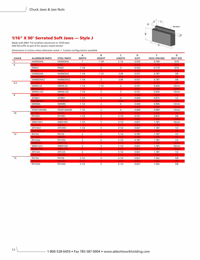
1/16" X 90° Serrated Soft Jaws — Style JMade with 6061 T-6 condition aluminum or 1018 steel
Add SQ suffix to part # for square nosed version
Dimensions in inches unless otherwise noted • Custom configurations available
A B C D F G
CHUCK ALUMInUM PART# STeeL PART# WIDTH HeIGHT LenGTH SLOT HOLe SPACInG BOLT SIZe
5 HAR5ESHA HAR5ESHS 1 1 1/4 2 1/2 0.433 0.709 5/16
6 PH6A PH6S 1 1/4 1 1/2 3 0.433 0.719 5/16
PH6A1 PH6S1 1 1/4 2 3 0.433 0.719 5/16
PH6A2 PH6S2 1 1/4 3 3 0.433 0.719 5/16
HAR6ESHA HAR6ESHS 1 1/4 1 1/2 3.09 0.551 0.787 3/8
HAR6ESHA1 HAR6ESHS1 1 1/4 2 3.09 0.551 0.787 3/8
HAR6ESHA2 HAR6ESHS2 1 1/4 3 3.09 0.551 0.787 3/8
6.5 PH6.5A PH6.5S 1 1/4 1 1/2 3 0.551 0.719 3/8
SMW6.5A SMW6.5S 1 1/4 1 1/2 3 0.551 0.650 10mm
SMW6.5A1 SMW6.5S1 1 1/4 2 3 0.551 0.650 10mm
SMW6.5A2 SMW6.5S2 1 1/4 3 3 0.551 0.650 10mm
8 ATS8A ATS8S 1 1/2 2 4 0.669 0.875 1/2
ATS8A1 ATS8S1 1 1/2 3 4 0.669 0.875 1/2
HAR8ESHA HAR8ESHS 1 1/2 2 3.68 0.669 0.880 7/16
SMW8A SMW8S 1 1/2 2 4 0.669 0.906 12mm
SMW8A1 SMW8S1 1 1/2 3 4 0.669 0.906 12mm
HOW12MA8A HOW12MA8S 1 1/2 2 4 0.669 0.984 12mm
10 PH10A PH10S 1 1/2 2 4 1/2 0.551 0.875 3/8
PH10A1 PH10S1 1 1/2 3 4 1/2 0.551 0.875 3/8
SMW10A SMW10S 1 1/2 2 4 1/2 0.827 1.181 16mm
SMW10A1 SMW10S1 1 1/2 3 4 1/2 0.827 1.181 16mm
ATS10A ATS10S 1 1/2 2 4 1/2 0.827 1.187 1/2
ATS10A1 ATS10S1 1 1/2 3 4 1/2 0.827 1.187 1/2
HAR10ESHA HAR10ESHS 1 1/2 2 4.72 0.827 1.187 5/8
12 PH12A PH12S 2 2 5 1/2 0.787 1.187 1/2
PH12A1 PH12S1 2 3 5 1/2 0.787 1.187 1/2
PH12A2 PH12S2 2 4 5 1/2 0.787 1.187 1/2
SMW12A SMW12S 2 2 5 1/2 0.827 1.181 16mm
SMW12A1 SMW12S1 2 3 5 1/2 0.827 1.181 16mm
SMW12A2 SMW12S2 2 4 5 1/2 0.827 1.181 16mm
ATS12A ATS12S 2 2 5 1/2 0.827 1.187 1/2
ATS12A1 ATS12S1 2 3 5 1/2 0.827 1.187 1/2
15 PH15A PH15S 2 1/2 3 6 1/2 0.827 1.562 5/8
PH15A1 PH15S1 2 1/2 4 6 1/2 0.827 1.562 5/8
PH15A5 PH15S5 2 1/2 5 6 1/2 0.827 1.562 5/8
15
Chuck Jaws & Jaw Nuts
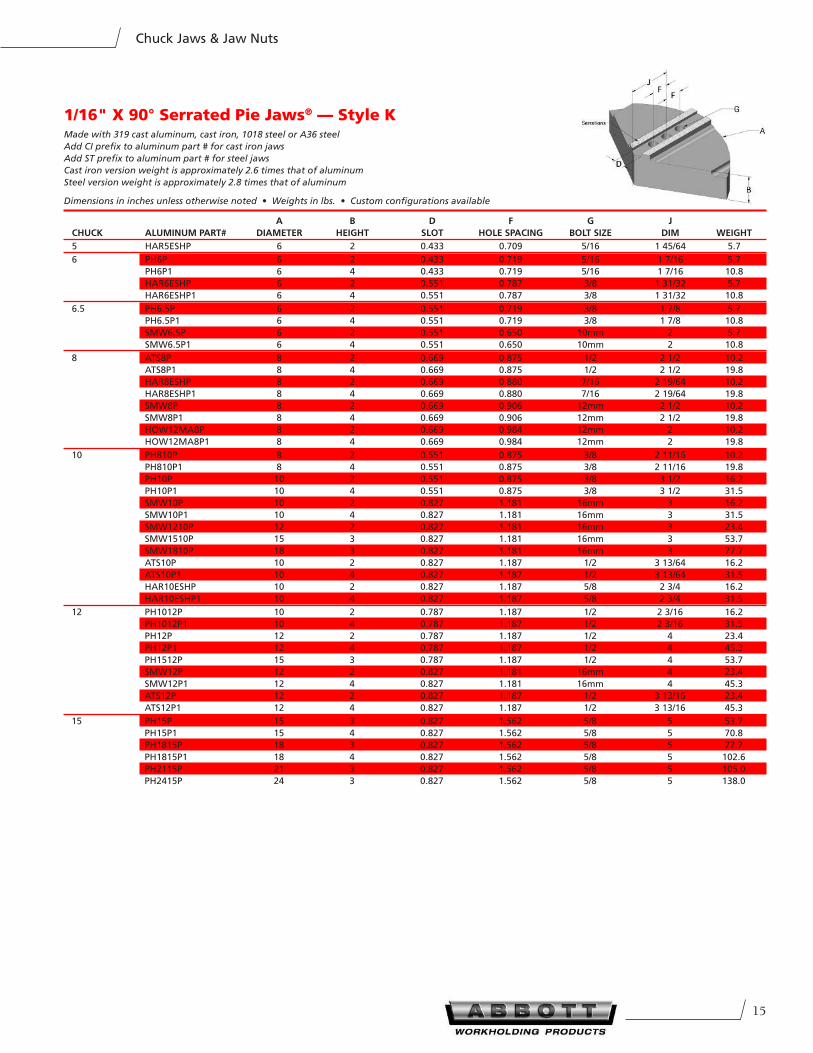
1/16" X 90° Serrated Pie Jaws® — Style KMade with 319 cast aluminum, cast iron, 1018 steel or A36 steel
Add CI prefix to aluminum part # for cast iron jaws
Add ST prefix to aluminum part # for steel jaws
Cast iron version weight is approximately 2.6 times that of aluminum
Steel version weight is approximately 2.8 times that of aluminum
Dimensions in inches unless otherwise noted • Weights in lbs. • Custom configurations available
A B D F G J
CHUCK ALUMInUM PART# DIAMeTeR HeIGHT SLOT HOLe SPACInG BOLT SIZe DIM WeIGHT
5 HAR5ESHP 6 2 0.433 0.709 5/16 1 45/64 5.7
6 PH6P 6 2 0.433 0.719 5/16 1 7/16 5.7
PH6P1 6 4 0.433 0.719 5/16 1 7/16 10.8
HAR6ESHP 6 2 0.551 0.787 3/8 1 31/32 5.7
HAR6ESHP1 6 4 0.551 0.787 3/8 1 31/32 10.8
6.5 PH6.5P 6 2 0.551 0.719 3/8 1 7/8 5.7
PH6.5P1 6 4 0.551 0.719 3/8 1 7/8 10.8
SMW6.5P 6 2 0.551 0.650 10mm 2 5.7
SMW6.5P1 6 4 0.551 0.650 10mm 2 10.8
8 ATS8P 8 2 0.669 0.875 1/2 2 1/2 10.2
ATS8P1 8 4 0.669 0.875 1/2 2 1/2 19.8
HAR8ESHP 8 2 0.669 0.880 7/16 2 19/64 10.2
HAR8ESHP1 8 4 0.669 0.880 7/16 2 19/64 19.8
SMW8P 8 2 0.669 0.906 12mm 2 1/2 10.2
SMW8P1 8 4 0.669 0.906 12mm 2 1/2 19.8
HOW12MA8P 8 2 0.669 0.984 12mm 2 10.2
HOW12MA8P1 8 4 0.669 0.984 12mm 2 19.8
10 PH810P 8 2 0.551 0.875 3/8 2 11/16 10.2
PH810P1 8 4 0.551 0.875 3/8 2 11/16 19.8
PH10P 10 2 0.551 0.875 3/8 3 1/2 16.2
PH10P1 10 4 0.551 0.875 3/8 3 1/2 31.5
SMW10P 10 2 0.827 1.181 16mm 3 16.2
SMW10P1 10 4 0.827 1.181 16mm 3 31.5
SMW1210P 12 2 0.827 1.181 16mm 3 23.4
SMW1510P 15 3 0.827 1.181 16mm 3 53.7
SMW1810P 18 3 0.827 1.181 16mm 3 77.7
ATS10P 10 2 0.827 1.187 1/2 3 13/64 16.2
ATS10P1 10 4 0.827 1.187 1/2 3 13/64 31.5
HAR10ESHP 10 2 0.827 1.187 5/8 2 3/4 16.2
HAR10ESHP1 10 4 0.827 1.187 5/8 2 3/4 31.5
12 PH1012P 10 2 0.787 1.187 1/2 2 3/16 16.2
PH1012P1 10 4 0.787 1.187 1/2 2 3/16 31.5
PH12P 12 2 0.787 1.187 1/2 4 23.4
PH12P1 12 4 0.787 1.187 1/2 4 45.3
PH1512P 15 3 0.787 1.187 1/2 4 53.7
SMW12P 12 2 0.827 1.181 16mm 4 23.4
SMW12P1 12 4 0.827 1.181 16mm 4 45.3
ATS12P 12 2 0.827 1.187 1/2 3 13/16 23.4
ATS12P1 12 4 0.827 1.187 1/2 3 13/16 45.3
15 PH15P 15 3 0.827 1.562 5/8 5 53.7
PH15P1 15 4 0.827 1.562 5/8 5 70.8
PH1815P 18 3 0.827 1.562 5/8 5 77.7
PH1815P1 18 4 0.827 1.562 5/8 5 102.6
PH2115P 21 3 0.827 1.562 5/8 5 105.0
PH2415P 24 3 0.827 1.562 5/8 5 138.0
161-800-528-6459 • Fax 785-587-0004 • www.abbottworkholding.com
Chuck Jaws & Jaw Nuts
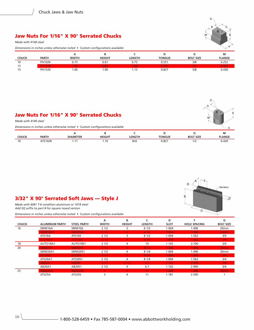
Jaw Nuts For 1/16" X 90° Serrated ChucksMade with 4140 steel
Dimensions in inches unless otherwise noted • Custom configurations available
A B C D G M
CHUCK PART# WIDTH HeIGHT LenGTH TOnGUe BOLT SIZe FLAnGe
10 PH10JN 0.75 0.61 0.75 0.551 3/8 0.252
12 PH12JN 1.00 0.85 1.00 0.787 1/2 0.325
15 PH15JN 1.00 1.00 1.13 0.827 5/8 0.430
Jaw Nuts For 1/16" X 90° Serrated ChucksMade with 4140 steel
Dimensions in inches unless otherwise noted • Custom configurations available
A B C D G M
CHUCK PART# DIAMeTeR HeIGHT LenGTH TOnGUe BOLT SIZe FLAnGe
10 ATS10JN 1.17 1.10 N/A 0.827 1/2 0.420
3/32" X 90° Serrated Soft Jaws — Style JMade with 6061 T-6 condition aluminum or 1018 steel
Add SQ suffix to part # for square nosed version
Dimensions in inches unless otherwise noted • Custom configurations available
A B C D F G
CHUCK ALUMInUM PART# STeeL PART# WIDTH HeIGHT LenGTH SLOT HOLe SPACInG BOLT SIZe
16 SMW16A SMW16S 2 1/2 3 6 1/2 1.004 1.496 20mm
SMW16A1 SMW16S1 2 1/2 4 6 1/2 1.004 1.496 20mm
ATS16A ATS16S 2 1/2 3 6 1/2 1.004 1.562 3/4
ATS16A1 ATS16S1 2 1/2 4 6 1/2 1.004 1.562 3/4
18 AUTO18A1 AUTO18S1 2 1/2 4 10 1.102 2.700 3/4
20 SMW20A SMW20S 2 1/2 3 8 1/4 1.004 1.496 20mm
SMW20A1 SMW20S1 2 1/2 4 8 1/4 1.004 1.496 20mm
ATS20A ATS20S 2 1/2 3 8 1/4 1.004 1.562 3/4
ATS20A1 ATS20S1 2 1/2 4 8 1/4 1.004 1.562 3/4
AB20A AB20S 2 1/2 2 1/2 6.7 1.102 2.990 3/4
AB20A1 AB20S1 2 1/2 4 6.7 1.102 2.990 3/4
25 SMW25A SMW25S 3 4 11 1.004 1.496 20mm
ATS25A ATS25S 3 4 11 1.181 2.500 1
17
Chuck Jaws & Jaw Nuts
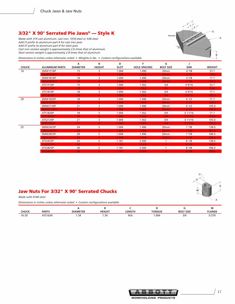
3/32" X 90° Serrated Pie Jaws® — Style KMade with 319 cast aluminum, cast iron, 1018 steel or A36 steel
Add CI prefix to aluminum part # for cast iron jaws
Add ST prefix to aluminum part # for steel jaws
Cast iron version weight is approximately 2.6 times that of aluminum
Steel version weight is approximately 2.8 times that of aluminum
Dimensions in inches unless otherwise noted • Weights in lbs. • Custom configurations available
A B D F G J
CHUCK ALUMInUM PART# DIAMeTeR HeIGHT SLOT HOLe SPACInG BOLT SIZe DIM WeIGHT
16 SMW1516P 15 3 1.004 1.496 20mm 4 7/8 53.7
SMW1516P1 15 4 1.004 1.496 20mm 4 7/8 70.8
SMW1816P 18 3 1.004 1.496 20mm 4 7/8 77.7
SMW1816P1 18 4 1.004 1.496 20mm 4 7/8 102.6
ATS1516P 15 3 1.004 1.562 3/4 4 9/16 53.7
ATS1516P1 15 4 1.004 1.562 3/4 4 9/16 70.8
ATS1816P 18 3 1.004 1.562 3/4 4 9/16 77.7
ATS1816P1 18 4 1.004 1.562 3/4 4 9/16 102.6
20 SMW1820P 18 3 1.004 1.496 20mm 6 1/2 77.7
SMW1820P1 18 4 1.004 1.496 20mm 6 1/2 102.6
SMW2120P 21 3 1.004 1.496 20mm 6 1/2 105.0
SMW2120P1 21 4 1.004 1.496 20mm 6 1/2 139.2
ATS1820P 18 3 1.004 1.562 3/4 6 11/16 77.7
ATS1820P1 18 4 1.004 1.562 3/4 6 11/16 102.6
ATS2120P 21 3 1.004 1.562 3/4 6 11/16 105.0
ATS2120P1 21 4 1.004 1.562 3/4 6 11/16 139.2
25 SMW2425P 24 3 1.004 1.496 20mm 7 7/8 138.0
SMW2425P1 24 4 1.004 1.496 20mm 7 7/8 182.4
SMW2825P 28 3 1.004 1.496 20mm 7 7/8 186.0
SMW2825P1 28 4 1.004 1.496 20mm 7 7/8 249.6
ATS2425P 24 3 1.181 2.500 1 8 1/8 138.0
ATS2425P1 24 4 1.181 2.500 1 8 1/8 182.4
ATS2825P 28 3 1.181 2.500 1 8 1/8 186.0
ATS2825P1 28 4 1.181 2.500 1 8 1/8 249.6
Jaw Nuts For 3/32" X 90° Serrated ChucksMade with 4140 steel
Dimensions in inches unless otherwise noted • Custom configurations available
A B C D G M
CHUCK PART# DIAMeTeR HeIGHT LenGTH TOnGUe BOLT SIZe FLAnGe
16-20 ATS16JN 1.34 1.34 N/A 1.004 3/4 0.570
181-800-528-6459 • Fax 785-587-0004 • www.abbottworkholding.com
Chuck Jaws & Jaw Nuts
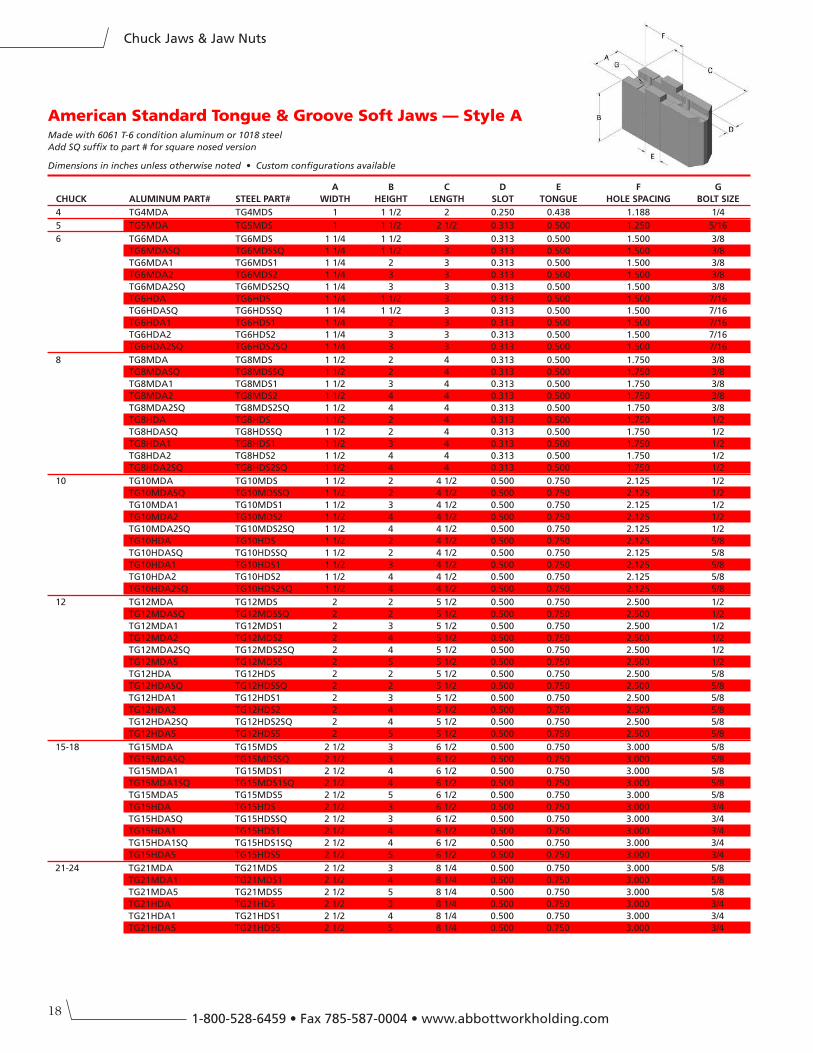
American Standard Tongue & Groove Soft Jaws — Style AMade with 6061 T-6 condition aluminum or 1018 steel
Add SQ suffix to part # for square nosed version
Dimensions in inches unless otherwise noted • Custom configurations available
A B C D e F G
CHUCK ALUMInUM PART# STeeL PART# WIDTH HeIGHT LenGTH SLOT TOnGUe HOLe SPACInG BOLT SIZe
4 TG4MDA TG4MDS 1 1 1/2 2 0.250 0.438 1.188 1/4
5 TG5MDA TG5MDS 1 1 1/2 2 1/2 0.313 0.500 1.250 5/16
6 TG6MDA TG6MDS 1 1/4 1 1/2 3 0.313 0.500 1.500 3/8
TG6MDASQ TG6MDSSQ 1 1/4 1 1/2 3 0.313 0.500 1.500 3/8
TG6MDA1 TG6MDS1 1 1/4 2 3 0.313 0.500 1.500 3/8
TG6MDA2 TG6MDS2 1 1/4 3 3 0.313 0.500 1.500 3/8
TG6MDA2SQ TG6MDS2SQ 1 1/4 3 3 0.313 0.500 1.500 3/8
TG6HDA TG6HDS 1 1/4 1 1/2 3 0.313 0.500 1.500 7/16
TG6HDASQ TG6HDSSQ 1 1/4 1 1/2 3 0.313 0.500 1.500 7/16
TG6HDA1 TG6HDS1 1 1/4 2 3 0.313 0.500 1.500 7/16
TG6HDA2 TG6HDS2 1 1/4 3 3 0.313 0.500 1.500 7/16
TG6HDA2SQ TG6HDS2SQ 1 1/4 3 3 0.313 0.500 1.500 7/16
8 TG8MDA TG8MDS 1 1/2 2 4 0.313 0.500 1.750 3/8
TG8MDASQ TG8MDSSQ 1 1/2 2 4 0.313 0.500 1.750 3/8
TG8MDA1 TG8MDS1 1 1/2 3 4 0.313 0.500 1.750 3/8
TG8MDA2 TG8MDS2 1 1/2 4 4 0.313 0.500 1.750 3/8
TG8MDA2SQ TG8MDS2SQ 1 1/2 4 4 0.313 0.500 1.750 3/8
TG8HDA TG8HDS 1 1/2 2 4 0.313 0.500 1.750 1/2
TG8HDASQ TG8HDSSQ 1 1/2 2 4 0.313 0.500 1.750 1/2
TG8HDA1 TG8HDS1 1 1/2 3 4 0.313 0.500 1.750 1/2
TG8HDA2 TG8HDS2 1 1/2 4 4 0.313 0.500 1.750 1/2
TG8HDA2SQ TG8HDS2SQ 1 1/2 4 4 0.313 0.500 1.750 1/2
10 TG10MDA TG10MDS 1 1/2 2 4 1/2 0.500 0.750 2.125 1/2
TG10MDASQ TG10MDSSQ 1 1/2 2 4 1/2 0.500 0.750 2.125 1/2
TG10MDA1 TG10MDS1 1 1/2 3 4 1/2 0.500 0.750 2.125 1/2
TG10MDA2 TG10MDS2 1 1/2 4 4 1/2 0.500 0.750 2.125 1/2
TG10MDA2SQ TG10MDS2SQ 1 1/2 4 4 1/2 0.500 0.750 2.125 1/2
TG10HDA TG10HDS 1 1/2 2 4 1/2 0.500 0.750 2.125 5/8
TG10HDASQ TG10HDSSQ 1 1/2 2 4 1/2 0.500 0.750 2.125 5/8
TG10HDA1 TG10HDS1 1 1/2 3 4 1/2 0.500 0.750 2.125 5/8
TG10HDA2 TG10HDS2 1 1/2 4 4 1/2 0.500 0.750 2.125 5/8
TG10HDA2SQ TG10HDS2SQ 1 1/2 4 4 1/2 0.500 0.750 2.125 5/8
12 TG12MDA TG12MDS 2 2 5 1/2 0.500 0.750 2.500 1/2
TG12MDASQ TG12MDSSQ 2 2 5 1/2 0.500 0.750 2.500 1/2
TG12MDA1 TG12MDS1 2 3 5 1/2 0.500 0.750 2.500 1/2
TG12MDA2 TG12MDS2 2 4 5 1/2 0.500 0.750 2.500 1/2
TG12MDA2SQ TG12MDS2SQ 2 4 5 1/2 0.500 0.750 2.500 1/2
TG12MDA5 TG12MDS5 2 5 5 1/2 0.500 0.750 2.500 1/2
TG12HDA TG12HDS 2 2 5 1/2 0.500 0.750 2.500 5/8
TG12HDASQ TG12HDSSQ 2 2 5 1/2 0.500 0.750 2.500 5/8
TG12HDA1 TG12HDS1 2 3 5 1/2 0.500 0.750 2.500 5/8
TG12HDA2 TG12HDS2 2 4 5 1/2 0.500 0.750 2.500 5/8
TG12HDA2SQ TG12HDS2SQ 2 4 5 1/2 0.500 0.750 2.500 5/8
TG12HDA5 TG12HDS5 2 5 5 1/2 0.500 0.750 2.500 5/8
15-18 TG15MDA TG15MDS 2 1/2 3 6 1/2 0.500 0.750 3.000 5/8
TG15MDASQ TG15MDSSQ 2 1/2 3 6 1/2 0.500 0.750 3.000 5/8
TG15MDA1 TG15MDS1 2 1/2 4 6 1/2 0.500 0.750 3.000 5/8
TG15MDA1SQ TG15MDS1SQ 2 1/2 4 6 1/2 0.500 0.750 3.000 5/8
TG15MDA5 TG15MDS5 2 1/2 5 6 1/2 0.500 0.750 3.000 5/8
TG15HDA TG15HDS 2 1/2 3 6 1/2 0.500 0.750 3.000 3/4
TG15HDASQ TG15HDSSQ 2 1/2 3 6 1/2 0.500 0.750 3.000 3/4
TG15HDA1 TG15HDS1 2 1/2 4 6 1/2 0.500 0.750 3.000 3/4
TG15HDA1SQ TG15HDS1SQ 2 1/2 4 6 1/2 0.500 0.750 3.000 3/4
TG15HDA5 TG15HDS5 2 1/2 5 6 1/2 0.500 0.750 3.000 3/4
21-24 TG21MDA TG21MDS 2 1/2 3 8 1/4 0.500 0.750 3.000 5/8
TG21MDA1 TG21MDS1 2 1/2 4 8 1/4 0.500 0.750 3.000 5/8
TG21MDA5 TG21MDS5 2 1/2 5 8 1/4 0.500 0.750 3.000 5/8
TG21HDA TG21HDS 2 1/2 3 8 1/4 0.500 0.750 3.000 3/4
TG21HDA1 TG21HDS1 2 1/2 4 8 1/4 0.500 0.750 3.000 3/4
TG21HDA5 TG21HDS5 2 1/2 5 8 1/4 0.500 0.750 3.000 3/4
19
Chuck Jaws & Jaw Nuts
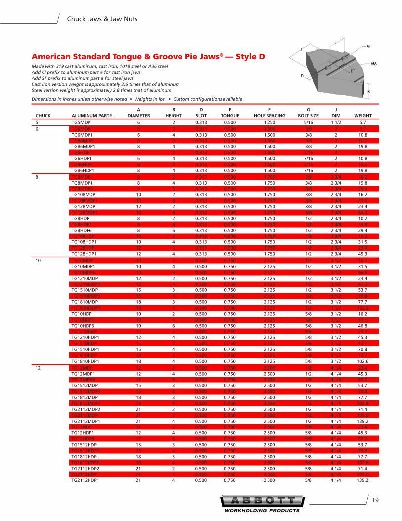
American Standard Tongue & Groove Pie Jaws® — Style DMade with 319 cast aluminum, cast iron, 1018 steel or A36 steel
Add CI prefix to aluminum part # for cast iron jaws
Add ST prefix to aluminum part # for steel jaws
Cast iron version weight is approximately 2.6 times that of aluminum
Steel version weight is approximately 2.8 times that of aluminum
Dimensions in inches unless otherwise noted • Weights in lbs. • Custom configurations available
A B D e F G J
CHUCK ALUMInUM PART# DIAMeTeR HeIGHT SLOT TOnGUe HOLe SPACInG BOLT SIZe DIM WeIGHT
5 TG5MDP 6 2 0.313 0.500 1.250 5/16 1 1/2 5.7
6 TG6MDP 6 2 0.313 0.500 1.500 3/8 2 5.7
TG6MDP1 6 4 0.313 0.500 1.500 3/8 2 10.8
TG86MDP 8 2 0.313 0.500 1.500 3/8 2 10.2
TG86MDP1 8 4 0.313 0.500 1.500 3/8 2 19.8
TG6HDP 6 2 0.313 0.500 1.500 7/16 2 5.7
TG6HDP1 6 4 0.313 0.500 1.500 7/16 2 10.8
TG86HDP 8 2 0.313 0.500 1.500 7/16 2 10.2
TG86HDP1 8 4 0.313 0.500 1.500 7/16 2 19.8
8 TG8MDP 8 2 0.313 0.500 1.750 3/8 2 3/4 10.2
TG8MDP1 8 4 0.313 0.500 1.750 3/8 2 3/4 19.8
TG8MDP6 8 6 0.313 0.500 1.750 3/8 2 3/4 29.4
TG108MDP 10 2 0.313 0.500 1.750 3/8 2 3/4 16.2
TG108MDP1 10 4 0.313 0.500 1.750 3/8 2 3/4 31.5
TG128MDP 12 2 0.313 0.500 1.750 3/8 2 3/4 23.4
TG128MDP1 12 4 0.313 0.500 1.750 3/8 2 3/4 45.3
TG8HDP 8 2 0.313 0.500 1.750 1/2 2 3/4 10.2
TG8HDP1 8 4 0.313 0.500 1.750 1/2 2 3/4 19.8
TG8HDP6 8 6 0.313 0.500 1.750 1/2 2 3/4 29.4
TG108HDP 10 2 0.313 0.500 1.750 1/2 2 3/4 16.2
TG108HDP1 10 4 0.313 0.500 1.750 1/2 2 3/4 31.5
TG128HDP 12 2 0.313 0.500 1.750 1/2 2 3/4 23.4
TG128HDP1 12 4 0.313 0.500 1.750 1/2 2 3/4 45.3
10 TG10MDP 10 2 0.500 0.750 2.125 1/2 3 1/2 16.2
TG10MDP1 10 4 0.500 0.750 2.125 1/2 3 1/2 31.5
TG10MDP6 10 6 0.500 0.750 2.125 1/2 3 1/2 46.8
TG1210MDP 12 2 0.500 0.750 2.125 1/2 3 1/2 23.4
TG1210MDP1 12 4 0.500 0.750 2.125 1/2 3 1/2 45.3
TG1510MDP 15 3 0.500 0.750 2.125 1/2 3 1/2 53.7
TG1510MDP1 15 4 0.500 0.750 2.125 1/2 3 1/2 70.8
TG1810MDP 18 3 0.500 0.750 2.125 1/2 3 1/2 77.7
TG1810MDP1 18 4 0.500 0.750 2.125 1/2 3 1/2 102.6
TG10HDP 10 2 0.500 0.750 2.125 5/8 3 1/2 16.2
TG10HDP1 10 4 0.500 0.750 2.125 5/8 3 1/2 31.5
TG10HDP6 10 6 0.500 0.750 2.125 5/8 3 1/2 46.8
TG1210HDP 12 2 0.500 0.750 2.125 5/8 3 1/2 23.4
TG1210HDP1 12 4 0.500 0.750 2.125 5/8 3 1/2 45.3
TG1510HDP 15 3 0.500 0.750 2.125 5/8 3 1/2 53.7
TG1510HDP1 15 4 0.500 0.750 2.125 5/8 3 1/2 70.8
TG1810HDP 18 3 0.500 0.750 2.125 5/8 3 1/2 77.7
TG1810HDP1 18 4 0.500 0.750 2.125 5/8 3 1/2 102.6
12 TG12MDP 12 2 0.500 0.750 2.500 1/2 4 1/4 23.4
TG12MDP1 12 4 0.500 0.750 2.500 1/2 4 1/4 45.3
TG12MDP6 12 6 0.500 0.750 2.500 1/2 4 1/4 67.2
TG1512MDP 15 3 0.500 0.750 2.500 1/2 4 1/4 53.7
TG1512MDP1 15 4 0.500 0.750 2.500 1/2 4 1/4 70.8
TG1812MDP 18 3 0.500 0.750 2.500 1/2 4 1/4 77.7
TG1812MDP1 18 4 0.500 0.750 2.500 1/2 4 1/4 102.6
TG2112MDP2 21 2 0.500 0.750 2.500 1/2 4 1/4 71.4
TG2112MDP 21 3 0.500 0.750 2.500 1/2 4 1/4 105.0
TG2112MDP1 21 4 0.500 0.750 2.500 1/2 4 1/4 139.2
TG12HDP 12 2 0.500 0.750 2.500 5/8 4 1/4 23.4
TG12HDP1 12 4 0.500 0.750 2.500 5/8 4 1/4 45.3
TG12HDP6 12 6 0.500 0.750 2.500 5/8 4 1/4 67.2
TG1512HDP 15 3 0.500 0.750 2.500 5/8 4 1/4 53.7
TG1512HDP1 15 4 0.500 0.750 2.500 5/8 4 1/4 70.8
TG1812HDP 18 3 0.500 0.750 2.500 5/8 4 1/4 77.7
TG1812HDP1 18 4 0.500 0.750 2.500 5/8 4 1/4 102.6
TG2112HDP2 21 2 0.500 0.750 2.500 5/8 4 1/4 71.4
TG2112HDP 21 3 0.500 0.750 2.500 5/8 4 1/4 105.0
TG2112HDP1 21 4 0.500 0.750 2.500 5/8 4 1/4 139.2
201-800-528-6459 • Fax 785-587-0004 • www.abbottworkholding.com
Chuck Jaws & Jaw Nuts
15 TG15MDP2 15 2 0.500 0.750 3.000 5/8 5 1/4 36.6
TG15MDP 15 3 0.500 0.750 3.000 5/8 5 1/4 53.7
TG15MDP1 15 4 0.500 0.750 3.000 5/8 5 1/4 70.8
TG15MDP6 15 6 0.500 0.750 3.000 5/8 5 1/4 88.5
TG1815MDP 18 3 0.500 0.750 3.000 5/8 5 1/4 77.7
TG1815MDP1 18 4 0.500 0.750 3.000 5/8 5 1/4 102.6
TG2115MDP2 21 2 0.500 0.750 3.000 5/8 5 1/4 71.4
TG2115MDP 21 3 0.500 0.750 3.000 5/8 5 1/4 105.0
TG2115MDP1 21 4 0.500 0.750 3.000 5/8 5 1/4 139.2
TG2415MDP2 24 2 0.500 0.750 3.000 5/8 5 1/4 93.0
TG2415MDP 24 3 0.500 0.750 3.000 5/8 5 1/4 138.0
TG2415MDP1 24 4 0.500 0.750 3.000 5/8 5 1/4 182.4
TG15HDP2 15 2 0.500 0.750 3.000 3/4 5 1/4 36.6
TG15HDP 15 3 0.500 0.750 3.000 3/4 5 1/4 53.7
TG15HDP1 15 4 0.500 0.750 3.000 3/4 5 1/4 70.8
TG15HDP6 15 6 0.500 0.750 3.000 3/4 5 1/4 88.5
TG1815HDP 18 3 0.500 0.750 3.000 3/4 5 1/4 77.7
TG1815HDP1 18 4 0.500 0.750 3.000 3/4 5 1/4 102.6
TG2115HDP2 21 2 0.500 0.750 3.000 3/4 5 1/4 71.4
TG2115HDP 21 3 0.500 0.750 3.000 3/4 5 1/4 105.0
TG2115HDP1 21 4 0.500 0.750 3.000 3/4 5 1/4 139.2
TG2415HDP2 24 2 0.500 0.750 3.000 3/4 5 1/4 93.0
TG2415HDP 24 3 0.500 0.750 3.000 3/4 5 1/4 138.0
TG2415HDP1 24 4 0.500 0.750 3.000 3/4 5 1/4 182.4
18 TG18MDP 18 3 0.500 0.750 3.000 5/8 6 1/2 77.7
TG18MDP1 18 4 0.500 0.750 3.000 5/8 6 1/2 102.6
TG18MDP8 18 8 0.500 0.750 3.000 5/8 6 1/2 203.1
TG2118MDP2 21 2 0.500 0.750 3.000 5/8 6 1/2 71.4
TG2118MDP 21 3 0.500 0.750 3.000 5/8 6 1/2 105.0
TG2118MDP1 21 4 0.500 0.750 3.000 5/8 6 1/2 139.2
TG2418MDP2 24 2 0.500 0.750 3.000 5/8 6 1/2 93.0
TG2418MDP 24 3 0.500 0.750 3.000 5/8 6 1/2 138.0
TG2418MDP1 24 4 0.500 0.750 3.000 5/8 6 1/2 182.4
TG2818MDP 28 3 0.500 0.750 3.000 5/8 6 1/2 186.0
TG2818MDP1 28 4 0.500 0.750 3.000 5/8 6 1/2 249.6
TG3018MDP1 30 4 0.500 0.750 3.000 5/8 6 1/2 286.5
TG322418MDP1 32 4 0.500 0.750 3.000 5/8 6 1/2 324.6
TG362418MDP1 36 4 0.500 0.750 3.000 5/8 6 1/2 412.5
TG18HDP 18 3 0.500 0.750 3.000 3/4 6 1/2 77.7
TG18HDP1 18 4 0.500 0.750 3.000 3/4 6 1/2 102.6
TG18HDP8 18 8 0.500 0.750 3.000 3/4 6 1/2 203.1
TG2118HDP2 21 2 0.500 0.750 3.000 3/4 6 1/2 71.4
TG2118HDP 21 3 0.500 0.750 3.000 3/4 6 1/2 105.0
TG2118HDP1 21 4 0.500 0.750 3.000 3/4 6 1/2 139.2
TG2418HDP2 24 2 0.500 0.750 3.000 3/4 6 1/2 93.0
TG2418HDP 24 3 0.500 0.750 3.000 3/4 6 1/2 138.0
TG2418HDP1 24 4 0.500 0.750 3.000 3/4 6 1/2 182.4
TG2818HDP 28 3 0.500 0.750 3.000 3/4 6 1/2 186.0
TG2818HDP1 28 4 0.500 0.750 3.000 3/4 6 1/2 249.6
TG3018HDP1 30 4 0.500 0.750 3.000 3/4 6 1/2 286.5
TG322418HDP1 32 4 0.500 0.750 3.000 3/4 6 1/2 324.6
TG362418HDP1 36 4 0.500 0.750 3.000 3/4 6 1/2 412.5
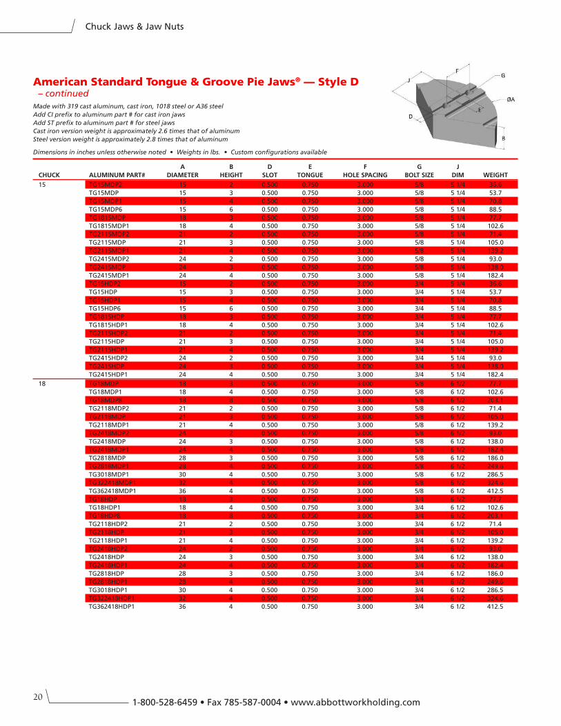
American Standard Tongue & Groove Pie Jaws® — Style D – continued
Made with 319 cast aluminum, cast iron, 1018 steel or A36 steel
Add CI prefix to aluminum part # for cast iron jaws
Add ST prefix to aluminum part # for steel jaws
Cast iron version weight is approximately 2.6 times that of aluminum
Steel version weight is approximately 2.8 times that of aluminum
Dimensions in inches unless otherwise noted • Weights in lbs. • Custom configurations available
A B D e F G J
CHUCK ALUMInUM PART# DIAMeTeR HeIGHT SLOT TOnGUe HOLe SPACInG BOLT SIZe DIM WeIGHT
21
Chuck Jaws & Jaw Nuts
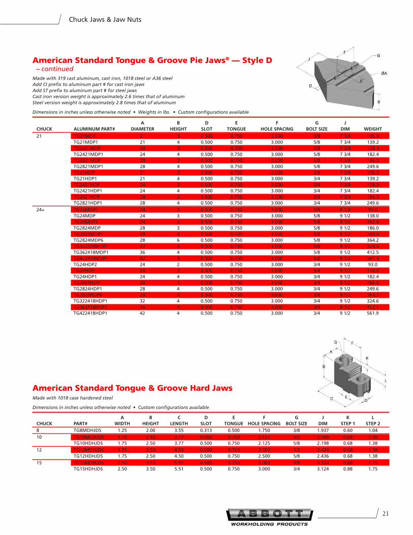
American Standard Tongue & Groove Hard JawsMade with 1018 case hardened steel
Dimensions in inches unless otherwise noted • Custom configurations available
A B C D e F G J K L
CHUCK PART# WIDTH HeIGHT LenGTH SLOT TOnGUe HOLe SPACInG BOLT SIZe DIM STeP 1 STeP 2
8 TG8MDHJDS 1.25 2.00 3.55 0.313 0.500 1.750 3/8 1.937 0.60 1.04
10 TG10MDHJDS 1.75 2.50 3.77 0.500 0.750 2.125 1/2 2.198 0.68 1.38
TG10HDHJDS 1.75 2.50 3.77 0.500 0.750 2.125 5/8 2.198 0.68 1.38
12 TG12MDHJDS 1.75 2.50 4.50 0.500 0.750 2.500 1/2 2.436 0.68 1.38
TG12HDHJDS 1.75 2.50 4.50 0.500 0.750 2.500 5/8 2.436 0.68 1.38
15 TG15MDHJDS 2.50 3.50 5.51 0.500 0.750 3.000 5/8 3.124 0.88 1.75
TG15HDHJDS 2.50 3.50 5.51 0.500 0.750 3.000 3/4 3.124 0.88 1.75
21 TG21MDP 21 3 0.500 0.750 3.000 5/8 7 3/4 105.0
TG21MDP1 21 4 0.500 0.750 3.000 5/8 7 3/4 139.2
TG2421MDP 24 3 0.500 0.750 3.000 5/8 7 3/4 138.0
TG2421MDP1 24 4 0.500 0.750 3.000 5/8 7 3/4 182.4
TG2821MDP 28 3 0.500 0.750 3.000 5/8 7 3/4 186.0
TG2821MDP1 28 4 0.500 0.750 3.000 5/8 7 3/4 249.6
TG21HDP 21 3 0.500 0.750 3.000 3/4 7 3/4 105.0
TG21HDP1 21 4 0.500 0.750 3.000 3/4 7 3/4 139.2
TG2421HDP 24 3 0.500 0.750 3.000 3/4 7 3/4 138.0
TG2421HDP1 24 4 0.500 0.750 3.000 3/4 7 3/4 182.4
TG2821HDP 28 3 0.500 0.750 3.000 3/4 7 3/4 186.0
TG2821HDP1 28 4 0.500 0.750 3.000 3/4 7 3/4 249.6
24+ TG24MDP2 24 2 0.500 0.750 3.000 5/8 9 1/2 93.0
TG24MDP 24 3 0.500 0.750 3.000 5/8 9 1/2 138.0
TG24MDP1 24 4 0.500 0.750 3.000 5/8 9 1/2 182.4
TG2824MDP 28 3 0.500 0.750 3.000 5/8 9 1/2 186.0
TG2824MDP1 28 4 0.500 0.750 3.000 5/8 9 1/2 249.6
TG2824MDP6 28 6 0.500 0.750 3.000 5/8 9 1/2 364.2
TG322418MDP1 32 4 0.500 0.750 3.000 5/8 9 1/2 324.6
TG362418MDP1 36 4 0.500 0.750 3.000 5/8 9 1/2 412.5
TG422418MDP1 42 4 0.500 0.750 3.000 5/8 9 1/2 561.9
TG24HDP2 24 2 0.500 0.750 3.000 3/4 9 1/2 93.0
TG24HDP 24 3 0.500 0.750 3.000 3/4 9 1/2 138.0
TG24HDP1 24 4 0.500 0.750 3.000 3/4 9 1/2 182.4
TG2824HDP 28 3 0.500 0.750 3.000 3/4 9 1/2 186.0
TG2824HDP1 28 4 0.500 0.750 3.000 3/4 9 1/2 249.6
TG2824HDP6 28 6 0.500 0.750 3.000 3/4 9 1/2 364.2
TG322418HDP1 32 4 0.500 0.750 3.000 3/4 9 1/2 324.6
TG362418HDP1 36 4 0.500 0.750 3.000 3/4 9 1/2 412.5
TG422418HDP1 42 4 0.500 0.750 3.000 3/4 9 1/2 561.9
American Standard Tongue & Groove Pie Jaws® — Style D – continued
Made with 319 cast aluminum, cast iron, 1018 steel or A36 steel
Add CI prefix to aluminum part # for cast iron jaws
Add ST prefix to aluminum part # for steel jaws
Cast iron version weight is approximately 2.6 times that of aluminum
Steel version weight is approximately 2.8 times that of aluminum
Dimensions in inches unless otherwise noted • Weights in lbs. • Custom configurations available
A B D e F G J
CHUCK ALUMInUM PART# DIAMeTeR HeIGHT SLOT TOnGUe HOLe SPACInG BOLT SIZe DIM WeIGHT
221-800-528-6459 • Fax 785-587-0004 • www.abbottworkholding.com
Chuck Jaws & Jaw Nuts
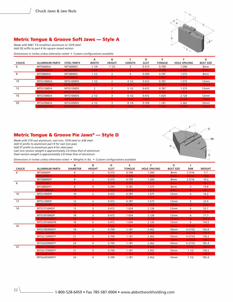
Metric Tongue & Groove Soft Jaws — Style AMade with 6061 T-6 condition aluminum or 1018 steel
Add SQ suffix to part # for square nosed version
Dimensions in inches unless otherwise noted • Custom configurations available
A B C D e F G
CHUCK ALUMInUM PART# STeeL PART# WIDTH HeIGHT LenGTH SLOT TOnGUe HOLe SPACInG BOLT SIZe
6 MTG6MDA MTG6MDS 1 1/4 1 1/2 3 0.315 0.709 1.260 8mm
MTG6MDA1 MTG6MDS1 1 1/4 2 3 0.315 0.709 1.260 8mm
8 MTG8MDA MTG8MDS 1 1/2 2 4 0.394 0.787 1.575 8mm
MTG8MDA1 MTG8MDS1 1 1/2 3 4 0.394 0.787 1.575 8mm
10 MTG10MDA MTG10MDS 1 1/2 2 4 1/2 0.472 0.787 1.575 12mm
MTG10MDA1 MTG10MDS1 1 1/2 3 4 1/2 0.472 0.787 1.575 12mm
12 MTG12MDA MTG12MDS 2 2 5 1/2 0.472 0.787 1.575 12mm
MTG12MDA1 MTG12MDS1 2 3 5 1/2 0.472 0.787 1.575 12mm
16 MTG16MDA MTG16MDS 2 1/2 3 6 1/2 0.472 1.024 2.126 12mm
MTG16MDA1 MTG16MDS1 2 1/2 4 6 1/2 0.472 1.024 2.126 12mm
20 MTG20MDA MTG20MDS 2 1/2 3 8 1/4 0.709 1.181 2.362 16mm
MTG20MDA1 MTG20MDS1 2 1/2 4 8 1/4 0.709 1.181 2.362 16mm
Metric Tongue & Groove Pie Jaws® — Style DMade with 319 cast aluminum, cast iron, 1018 steel or A36 steel
Add CI prefix to aluminum part # for cast iron jaws
Add ST prefix to aluminum part # for steel jaws
Cast iron version weight is approximately 2.6 times that of aluminum
Steel version weight is approximately 2.8 times that of aluminum
Dimensions in inches unless otherwise noted • Weights in lbs. • Custom configurations available
A B D e F G J
CHUCK ALUMInUM PART# DIAMeTeR HeIGHT SLOT TOnGUe HOLe SPACInG BOLT SIZe DIM WeIGHT
6 MTG6MDP 6 2 0.315 0.709 1.260 8mm 2 5/16 5.7
MTG6MDP1 6 4 0.315 0.709 1.260 8mm 2 5/16 10.8
MTG86MDP 8 2 0.315 0.709 1.260 8mm 2 5/16 10.2
8 MTG8MDP 8 2 0.394 0.787 1.575 8mm 3 10.2
MTG8MDP1 8 4 0.394 0.787 1.575 8mm 3 19.8
MTG108MDP 10 2 0.394 0.787 1.575 8mm 3 10.2
10 MTG10MDP 10 2 0.472 0.787 1.575 12mm 4 16.2
MTG10MDP1 10 4 0.472 0.787 1.575 12mm 4 31.5
12 MTG12MDP 12 2 0.472 0.787 1.575 12mm 5 23.4
MTG12MDP1 12 4 0.472 0.787 1.575 12mm 5 45.3
16 MTG1516MDP 15 3 0.472 1.024 2.126 12mm 6 53.7
MTG1516MDP1 15 4 0.472 1.024 2.126 12mm 6 70.8
MTG1816MDP 18 3 0.472 1.024 2.126 12mm 6 77.7
MTG1816MDP1 18 4 0.472 1.024 2.126 12mm 6 102.6
MTG1816MDP6 18 6 0.472 1.024 2.126 12mm 6 154.5
20 MTG1820MDP 18 3 0.709 1.181 2.362 16mm 4 27/32 77.7
MTG1820MDP1 18 4 0.709 1.181 2.362 16mm 4 27/32 102.6
MTG2120MDP 21 3 0.709 1.181 2.362 16mm 4 27/32 105.0
MTG2120MDP1 21 4 0.709 1.181 2.362 16mm 4 27/32 139.2
MTG2420MDP 24 3 0.709 1.181 2.362 16mm 4 27/32 138.0
MTG2420MDP1 24 4 0.709 1.181 2.362 16mm 4 27/32 182.4
25 MTG2125MDP 21 3 0.709 1.181 2.362 16mm 7 1/2 105.0
MTG2125MDP1 21 4 0.709 1.181 2.362 16mm 7 1/2 139.2
MTG2425MDP 24 3 0.709 1.181 2.362 16mm 7 1/2 138.0
MTG2425MDP1 24 4 0.709 1.181 2.362 16mm 7 1/2 182.4
23
Chuck Jaws & Jaw Nuts
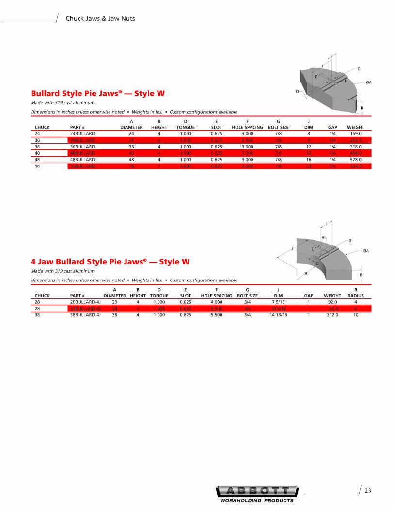
4 Jaw Bullard Style Pie Jaws® — Style WMade with 319 cast aluminum
Dimensions in inches unless otherwise noted • Weights in lbs. • Custom configurations available
A B D e F G J R
CHUCK PART # DIAMeTeR HeIGHT TOnGUe SLOT HOLe SPACInG BOLT SIZe DIM GAP WeIGHT RADIUS
20 20BULLARD-4J 20 4 1.000 0.625 4.000 3/4 7 5/16 1 92.0 4
28 28BULLARD-4J 28 4 1.000 0.625 5.500 3/4 10 5/16 1 182.0 6
38 38BULLARD-4J 38 4 1.000 0.625 5.500 3/4 14 13/16 1 312.0 10
Bullard Style Pie Jaws® — Style WMade with 319 cast aluminum
Dimensions in inches unless otherwise noted • Weights in lbs. • Custom configurations available
A B D e F G J
CHUCK PART # DIAMeTeR HeIGHT TOnGUe SLOT HOLe SPACInG BOLT SIZe DIM GAP WeIGHT
24 24BULLARD 24 4 1.000 0.625 3.000 7/8 8 1/4 159.0
30 30BULLARD 30 4 1.000 0.625 3.000 7/8 9 1/4 255.0
36 36BULLARD 36 4 1.000 0.625 3.000 7/8 12 1/4 318.0
40 40BULLARD 40 4 1.000 0.625 3.000 7/8 12 1/4 414.0
48 48BULLARD 48 4 1.000 0.625 3.000 7/8 16 1/4 528.0
56 56BULLARD 56 4 1.000 0.625 3.000 7/8 23 1/4 634.0
241-800-528-6459 • Fax 785-587-0004 • www.abbottworkholding.com
Chuck Jaws & Jaw Nuts
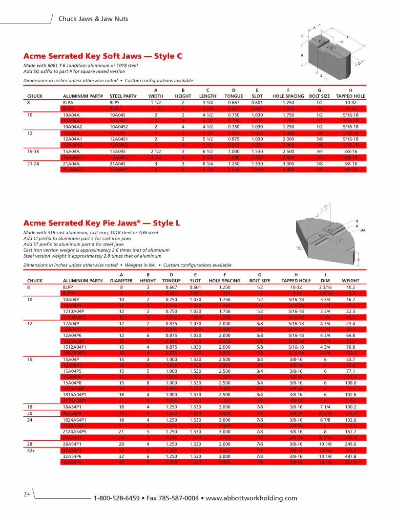
Acme Serrated Key Soft Jaws — Style CMade with 6061 T-6 condition aluminum or 1018 steel
Add SQ suffix to part # for square nosed version
Dimensions in inches unless otherwise noted • Custom configurations available
A B C D e F G H
CHUCK ALUMInUM PART# STeeL PART# WIDTH HeIGHT LenGTH TOnGUe SLOT HOLe SPACInG BOLT SIZe TAPPeD HOLe
8 8LPA 8LPS 1 1/2 2 3 1/4 0.667 0.601 1.250 1/2 10-32
8LPA1 8LPS1 1 1/2 3 3 1/4 0.667 0.601 1.250 1/2 10-32
10 10A04A 10A04S 2 2 4 1/2 0.750 1.030 1.750 1/2 5/16-18
10A04A1 10A04S1 2 3 4 1/2 0.750 1.030 1.750 1/2 5/16-18
10A04A2 10A04S2 2 4 4 1/2 0.750 1.030 1.750 1/2 5/16-18
12 12A04A 12A04S 2 2 5 1/2 0.875 1.030 2.000 5/8 5/16-18
12A04A1 12A04S1 2 3 5 1/2 0.875 1.030 2.000 5/8 5/16-18
12A04A2 12A04S2 2 4 5 1/2 0.875 1.030 2.000 5/8 5/16-18
15-18 15A04A 15A04S 2 1/2 3 6 1/2 1.000 1.530 2.500 3/4 3/8-16
15A04A1 15A04S1 2 1/2 4 6 1/2 1.000 1.530 2.500 3/4 3/8-16
21-24 21A04A 21A04S 3 3 8 1/4 1.250 1.530 3.000 7/8 3/8-16
21A04A1 21A04S1 3 4 8 1/4 1.250 1.530 3.000 7/8 3/8-16
Acme Serrated Key Pie Jaws® — Style LMade with 319 cast aluminum, cast iron, 1018 steel or A36 steel
Add CI prefix to aluminum part # for cast iron jaws
Add ST prefix to aluminum part # for steel jaws
Cast iron version weight is approximately 2.6 times that of aluminum
Steel version weight is approximately 2.8 times that of aluminum
Dimensions in inches unless otherwise noted • Weights in lbs. • Custom configurations available
A B D e F G H J
CHUCK ALUMInUM PART# DIAMeTeR HeIGHT TOnGUe SLOT HOLe SPACInG BOLT SIZe TAPPeD HOLe DIM WeIGHT
8 8LPP 8 2 0.667 0.601 1.250 1/2 10-32 3 3/16 10.2
8LPP1 8 4 0.667 0.601 1.250 1/2 10-32 3 3/16 19.8
10 10A04P 10 2 0.750 1.030 1.750 1/2 5/16-18 3 3/4 16.2
10A04P1 10 4 0.750 1.030 1.750 1/2 5/16-18 3 3/4 31.5
1210A04P 12 2 0.750 1.030 1.750 1/2 5/16-18 3 3/4 22.3
1210A04P1 12 4 0.750 1.030 1.750 1/2 5/16-18 3 3/4 45.3
12 12A04P 12 2 0.875 1.030 2.000 5/8 5/16-18 4 3/4 23.4
12A04P1 12 4 0.875 1.030 2.000 5/8 5/16-18 4 3/4 45.3
12A04P6 12 6 0.875 1.030 2.000 5/8 5/16-18 4 3/4 64.8
1512A04P 15 3 0.875 1.030 2.000 5/8 5/16-18 4 3/4 53.7
1512A04P1 15 4 0.875 1.030 2.000 5/8 5/16-18 4 3/4 70.8
1812A04P1 18 4 0.875 1.030 2.000 5/8 5/16-18 4 3/4 102.6
15 15A04P 15 3 1.000 1.530 2.500 3/4 3/8-16 6 53.7
15A04P1 15 4 1.000 1.530 2.500 3/4 3/8-16 6 70.8
15A04P5 15 5 1.000 1.530 2.500 3/4 3/8-16 6 77.1
15A04P6 15 6 1.000 1.530 2.500 3/4 3/8-16 6 105.0
15A04P8 15 8 1.000 1.530 2.500 3/4 3/8-16 6 138.0
1815A04P 18 3 1.000 1.530 2.500 3/4 3/8-16 6 77.7
1815A04P1 18 4 1.000 1.530 2.500 3/4 3/8-16 6 102.6
2115A04P1 21 4 1.000 1.530 2.500 3/4 3/8-16 6 139.2
18 18A54P1 18 4 1.250 1.530 3.000 7/8 3/8-16 7 1/4 100.2
20 20A54P4 20 4 1.250 1.530 3.000 7/8 3/8-16 8 1/16 124.5
24 1824A54P1 18 4 1.250 1.530 3.000 7/8 3/8-16 6 7/8 102.6
2124A54P1 21 4 1.250 1.530 3.000 7/8 3/8-16 8 133.5
2124A54P5 21 5 1.250 1.530 3.000 7/8 3/8-16 8 167.7
24A54P1 24 4 1.250 1.530 3.000 7/8 3/8-16 8 1/16 182.4
28 28A54P1 28 4 1.250 1.530 3.000 7/8 3/8-16 10 1/8 249.6
32+ 32A54P1 32 4 1.250 1.530 3.000 7/8 3/8-16 10 1/8 324.6
32A54P6 32 6 1.250 1.530 3.000 7/8 3/8-16 10 1/8 487.8
42A54P1 42 4 1.250 1.530 3.000 7/8 3/8-16 10 1/8 561.9
25
Chuck Jaws & Jaw Nuts
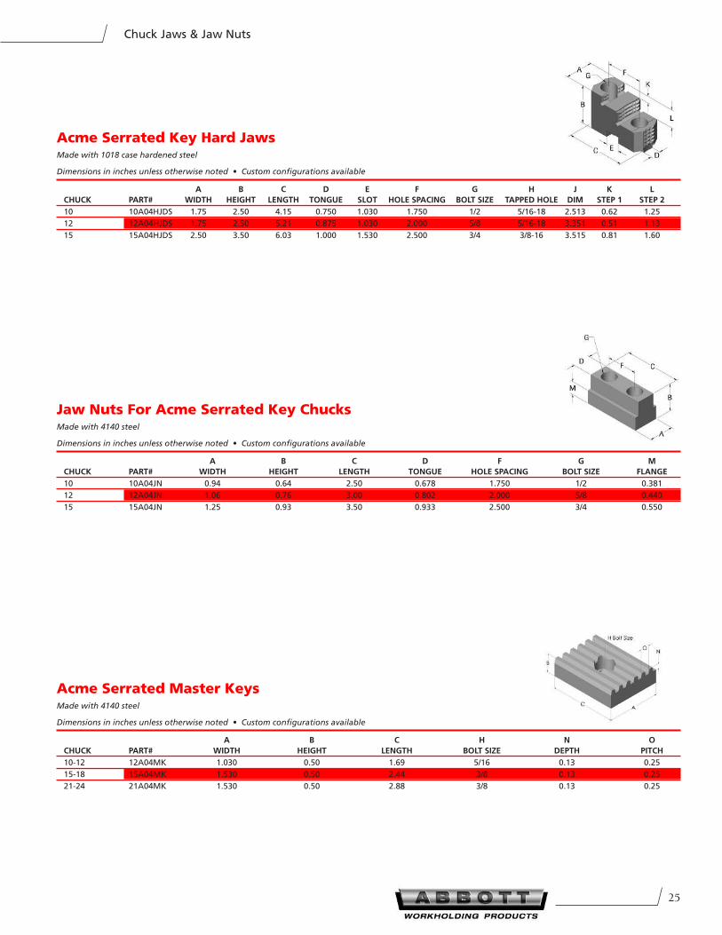
Acme Serrated Key Hard JawsMade with 1018 case hardened steel
Dimensions in inches unless otherwise noted • Custom configurations available
A B C D e F G H J K L
CHUCK PART# WIDTH HeIGHT LenGTH TOnGUe SLOT HOLe SPACInG BOLT SIZe TAPPeD HOLe DIM STeP 1 STeP 2
10 10A04HJDS 1.75 2.50 4.15 0.750 1.030 1.750 1/2 5/16-18 2.513 0.62 1.25
12 12A04HJDS 1.75 2.50 5.21 0.875 1.030 2.000 5/8 5/16-18 3.351 0.51 1.13
15 15A04HJDS 2.50 3.50 6.03 1.000 1.530 2.500 3/4 3/8-16 3.515 0.81 1.60
Jaw Nuts For Acme Serrated Key Chucks Made with 4140 steel
Dimensions in inches unless otherwise noted • Custom configurations available
A B C D F G M
CHUCK PART# WIDTH HeIGHT LenGTH TOnGUe HOLe SPACInG BOLT SIZe FLAnGe
10 10A04JN 0.94 0.64 2.50 0.678 1.750 1/2 0.381
12 12A04JN 1.06 0.76 3.00 0.802 2.000 5/8 0.440
15 15A04JN 1.25 0.93 3.50 0.933 2.500 3/4 0.550
Acme Serrated Master KeysMade with 4140 steel
Dimensions in inches unless otherwise noted • Custom configurations available
A B C H n O
CHUCK PART# WIDTH HeIGHT LenGTH BOLT SIZe DePTH PITCH
10-12 12A04MK 1.030 0.50 1.69 5/16 0.13 0.25
15-18 15A04MK 1.530 0.50 2.44 3/8 0.13 0.25
21-24 21A04MK 1.530 0.50 2.88 3/8 0.13 0.25
261-800-528-6459 • Fax 785-587-0004 • www.abbottworkholding.com
Chuck Jaws & Jaw Nuts
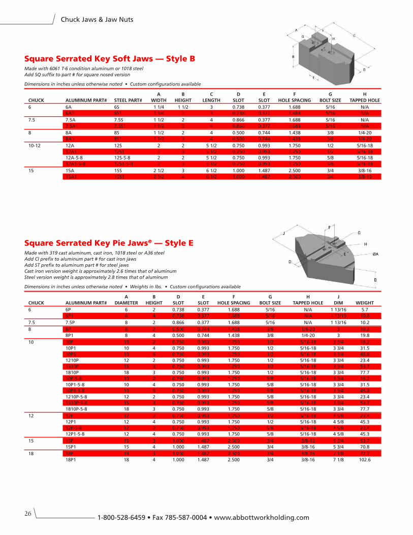
Square Serrated Key Pie Jaws® — Style EMade with 319 cast aluminum, cast iron, 1018 steel or A36 steel
Add CI prefix to aluminum part # for cast iron jaws
Add ST prefix to aluminum part # for steel jaws
Cast iron version weight is approximately 2.6 times that of aluminum
Steel version weight is approximately 2.8 times that of aluminum
Dimensions in inches unless otherwise noted • Weights in lbs. • Custom configurations available
A B D e F G H J
CHUCK ALUMInUM PART# DIAMeTeR HeIGHT SLOT SLOT HOLe SPACInG BOLT SIZe TAPPeD HOLe DIM WeIGHT
6 6P 6 2 0.738 0.377 1.688 5/16 N/A 1 13/16 5.7
6P1 6 4 0.738 0.377 1.688 5/16 N/A 1 13/16 10.8
7.5 7.5P 8 2 0.866 0.377 1.688 5/16 N/A 1 13/16 10.2
8 8P 8 2 0.500 0.744 1.438 3/8 1/4-20 3 10.2
8P1 8 4 0.500 0.744 1.438 3/8 1/4-20 3 19.8
10 10P 10 2 0.750 0.993 1.750 1/2 5/16-18 3 3/4 16.2
10P1 10 4 0.750 0.993 1.750 1/2 5/16-18 3 3/4 31.5
10P6 10 6 0.750 0.993 1.750 1/2 5/16-18 3 3/4 46.8
1210P 12 2 0.750 0.993 1.750 1/2 5/16-18 3 3/4 23.4
1510P 15 3 0.750 0.993 1.750 1/2 5/16-18 3 3/4 53.7
1810P 18 3 0.750 0.993 1.750 1/2 5/16-18 3 3/4 77.7
10P-5-8 10 2 0.750 0.993 1.750 5/8 5/16-18 3 3/4 16.2
10P1-5-8 10 4 0.750 0.993 1.750 5/8 5/16-18 3 3/4 31.5
10P6-5-8 10 6 0.750 0.993 1.750 5/8 5/16-18 3 3/4 46.8
1210P-5-8 12 2 0.750 0.993 1.750 5/8 5/16-18 3 3/4 23.4
1510P-5-8 15 3 0.750 0.993 1.750 5/8 5/16-18 3 3/4 53.7
1810P-5-8 18 3 0.750 0.993 1.750 5/8 5/16-18 3 3/4 77.7
12 12P 12 2 0.750 0.993 1.750 1/2 5/16-18 4 5/8 23.4
12P1 12 4 0.750 0.993 1.750 1/2 5/16-18 4 5/8 45.3
12P-5-8 12 2 0.750 0.993 1.750 5/8 5/16-18 4 5/8 23.4
12P1-5-8 12 4 0.750 0.993 1.750 5/8 5/16-18 4 5/8 45.3
15 15P 15 3 1.000 1.487 2.500 3/4 3/8-16 5 3/4 53.7
15P1 15 4 1.000 1.487 2.500 3/4 3/8-16 5 3/4 70.8
18 18P 18 3 1.000 1.487 2.500 3/4 3/8-16 7 1/8 77.7
18P1 18 4 1.000 1.487 2.500 3/4 3/8-16 7 1/8 102.6
Square Serrated Key Soft Jaws — Style BMade with 6061 T-6 condition aluminum or 1018 steel
Add SQ suffix to part # for square nosed version
Dimensions in inches unless otherwise noted • Custom configurations available
A B C D e F G H
CHUCK ALUMInUM PART# STeeL PART# WIDTH HeIGHT LenGTH SLOT SLOT HOLe SPACInG BOLT SIZe TAPPeD HOLe
6 6A 6S 1 1/4 1 1/2 3 0.738 0.377 1.688 5/16 N/A
6A1 6S1 1 1/4 2 3 0.738 0.377 1.688 5/16 N/A
7.5 7.5A 7.5S 1 1/2 2 4 0.866 0.377 1.688 5/16 N/A
7.5A1 7.5S1 1 1/2 3 4 0.866 0.377 1.688 5/16 N/A
8 8A 8S 1 1/2 2 4 0.500 0.744 1.438 3/8 1/4-20
8A1 8S1 1 1/2 3 4 0.500 0.744 1.438 3/8 1/4-20
10-12 12A 12S 2 2 5 1/2 0.750 0.993 1.750 1/2 5/16-18
12A1 12S1 2 3 5 1/2 0.750 0.993 1.750 1/2 5/16-18
12A-5-8 12S-5-8 2 2 5 1/2 0.750 0.993 1.750 5/8 5/16-18
12A1-5-8 12S1-5-8 2 3 5 1/2 0.750 0.993 1.750 5/8 5/16-18
15 15A 15S 2 1/2 3 6 1/2 1.000 1.487 2.500 3/4 3/8-16
15A1 15S1 2 1/2 4 6 1/2 1.000 1.487 2.500 3/4 3/8-16
27
Chuck Jaws & Jaw Nuts
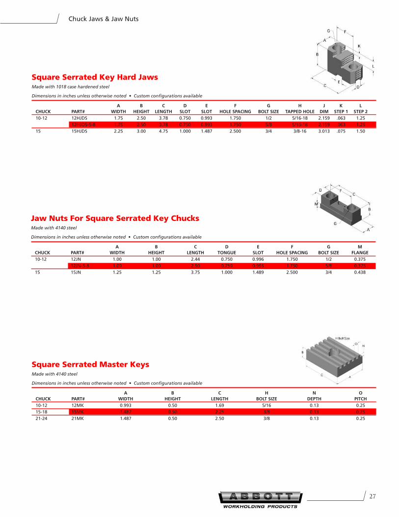
Jaw Nuts For Square Serrated Key ChucksMade with 4140 steel
Dimensions in inches unless otherwise noted • Custom configurations available
A B C D e F G M
CHUCK PART# WIDTH HeIGHT LenGTH TOnGUe SLOT HOLe SPACInG BOLT SIZe FLAnGe
10-12 12JN 1.00 1.00 2.44 0.750 0.996 1.750 1/2 0.375
12JN-5-8 1.00 1.00 2.50 0.750 0.996 1.750 5/8 0.375
15 15JN 1.25 1.25 3.75 1.000 1.489 2.500 3/4 0.438
Square Serrated Key Hard JawsMade with 1018 case hardened steel
Dimensions in inches unless otherwise noted • Custom configurations available
A B C D e F G H J K L
CHUCK PART# WIDTH HeIGHT LenGTH SLOT SLOT HOLe SPACInG BOLT SIZe TAPPeD HOLe DIM STeP 1 STeP 2
10-12 12HJDS 1.75 2.50 3.78 0.750 0.993 1.750 1/2 5/16-18 2.159 .063 1.25
12HJDS-5-8 1.75 2.50 3.78 0.750 0.993 1.750 5/8 5/16-18 2.159 .063 1.25
15 15HJDS 2.25 3.00 4.75 1.000 1.487 2.500 3/4 3/8-16 3.013 .075 1.50
Square Serrated Master KeysMade with 4140 steel
Dimensions in inches unless otherwise noted • Custom configurations available
A B C H n O
CHUCK PART# WIDTH HeIGHT LenGTH BOLT SIZe DePTH PITCH
10-12 12MK 0.993 0.50 1.69 5/16 0.13 0.25
15-18 15MK 1.487 0.50 2.25 3/8 0.13 0.25
21-24 21MK 1.487 0.50 2.50 3/8 0.13 0.25
281-800-528-6459 • Fax 785-587-0004 • www.abbottworkholding.com
Chuck Jaws & Jaw Nuts
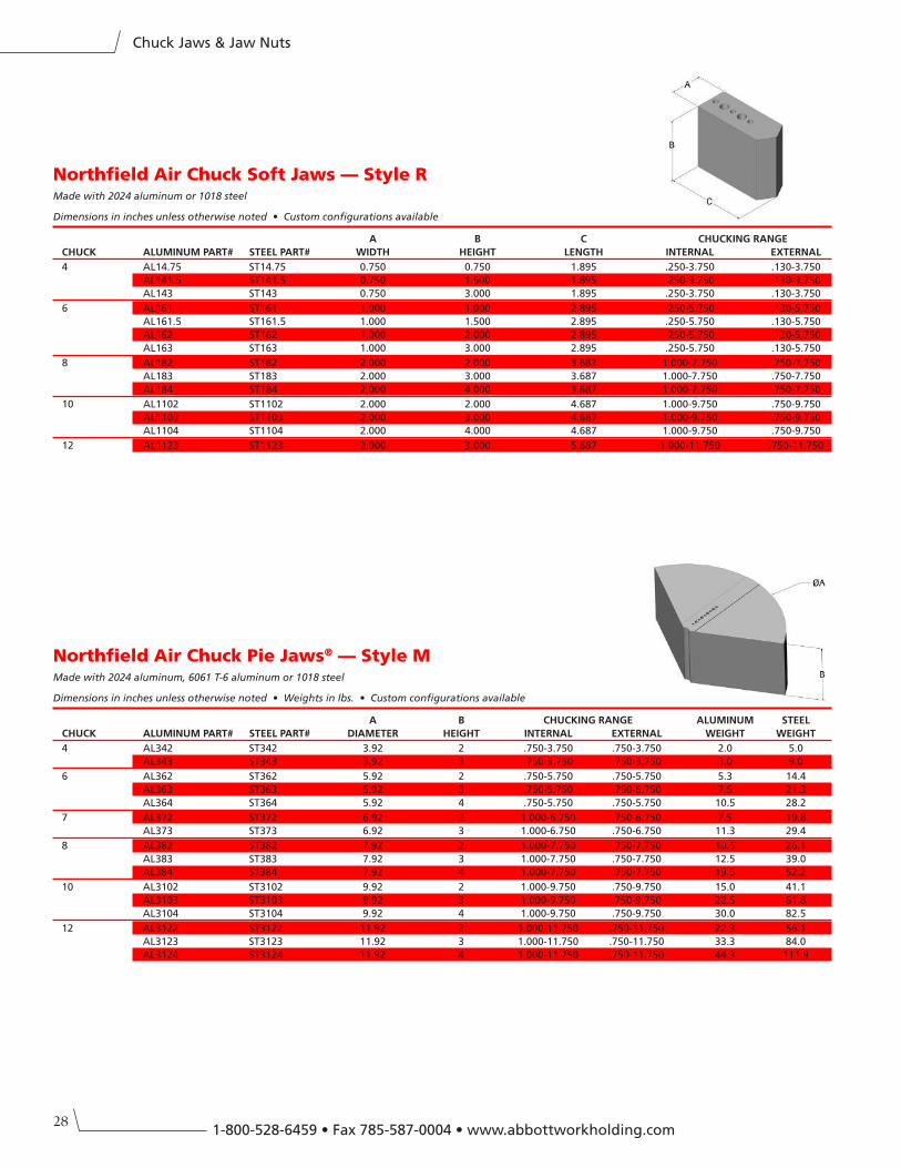
Northfield Air Chuck Soft Jaws — Style RMade with 2024 aluminum or 1018 steel
Dimensions in inches unless otherwise noted • Custom configurations available
A B C CHUCKInG RAnGe
CHUCK ALUMInUM PART# STeeL PART# WIDTH HeIGHT LenGTH InTeRnAL eXTeRnAL
4 AL14.75 ST14.75 0.750 0.750 1.895 .250-3.750 .130-3.750
AL141.5 ST141.5 0.750 1.500 1.895 .250-3.750 .130-3.750
AL143 ST143 0.750 3.000 1.895 .250-3.750 .130-3.750
6 AL161 ST161 1.000 1.000 2.895 .250-5.750 .130-5.750
AL161.5 ST161.5 1.000 1.500 2.895 .250-5.750 .130-5.750
AL162 ST162 1.000 2.000 2.895 .250-5.750 .130-5.750
AL163 ST163 1.000 3.000 2.895 .250-5.750 .130-5.750
8 AL182 ST182 2.000 2.000 3.687 1.000-7.750 .750-7.750
AL183 ST183 2.000 3.000 3.687 1.000-7.750 .750-7.750
AL184 ST184 2.000 4.000 3.687 1.000-7.750 .750-7.750
10 AL1102 ST1102 2.000 2.000 4.687 1.000-9.750 .750-9.750
AL1103 ST1103 2.000 3.000 4.687 1.000-9.750 .750-9.750
AL1104 ST1104 2.000 4.000 4.687 1.000-9.750 .750-9.750
12 AL1123 ST1123 2.000 3.000 5.687 1.000-11.750 .750-11.750
Northfield Air Chuck Pie Jaws® — Style MMade with 2024 aluminum, 6061 T-6 aluminum or 1018 steel
Dimensions in inches unless otherwise noted • Weights in lbs. • Custom configurations available
A B CHUCKInG RAnGe ALUMInUM STeeL
CHUCK ALUMInUM PART# STeeL PART# DIAMeTeR HeIGHT InTeRnAL eXTeRnAL WeIGHT WeIGHT
4 AL342 ST342 3.92 2 .750-3.750 .750-3.750 2.0 5.0
AL343 ST343 3.92 3 .750-3.750 .750-3.750 3.0 9.0
6 AL362 ST362 5.92 2 .750-5.750 .750-5.750 5.3 14.4
AL363 ST363 5.92 3 .750-5.750 .750-5.750 7.5 21.3
AL364 ST364 5.92 4 .750-5.750 .750-5.750 10.5 28.2
7 AL372 ST372 6.92 2 1.000-6.750 .750-6.750 7.5 19.8
AL373 ST373 6.92 3 1.000-6.750 .750-6.750 11.3 29.4
8 AL382 ST382 7.92 2 1.000-7.750 .750-7.750 10.5 26.1
AL383 ST383 7.92 3 1.000-7.750 .750-7.750 12.5 39.0
AL384 ST384 7.92 4 1.000-7.750 .750-7.750 19.5 52.2
10 AL3102 ST3102 9.92 2 1.000-9.750 .750-9.750 15.0 41.1
AL3103 ST3103 9.92 3 1.000-9.750 .750-9.750 22.5 61.8
AL3104 ST3104 9.92 4 1.000-9.750 .750-9.750 30.0 82.5
12 AL3122 ST3122 11.92 2 1.000-11.750 .750-11.750 22.3 56.1
AL3123 ST3123 11.92 3 1.000-11.750 .750-11.750 33.3 84.0
AL3124 ST3124 11.92 4 1.000-11.750 .750-11.750 44.3 111.9
29
Chuck Jaws & Jaw Nuts
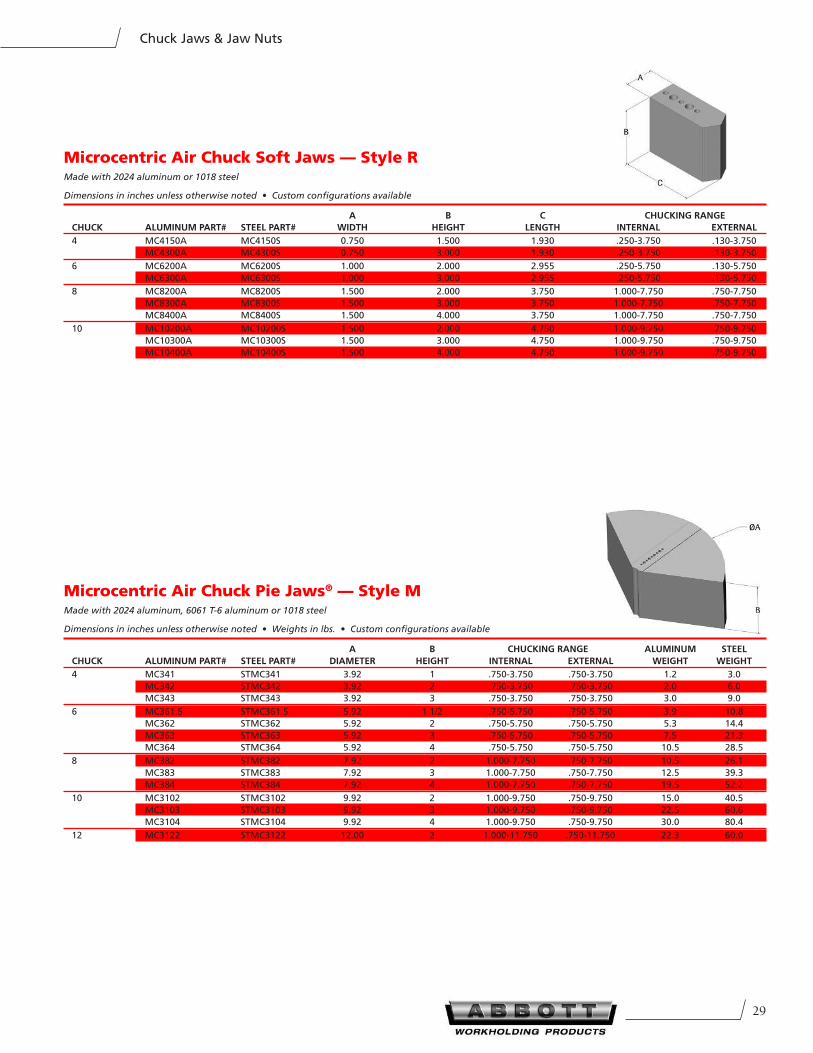
Microcentric Air Chuck Soft Jaws — Style RMade with 2024 aluminum or 1018 steel
Dimensions in inches unless otherwise noted • Custom configurations available
A B C CHUCKInG RAnGe
CHUCK ALUMInUM PART# STeeL PART# WIDTH HeIGHT LenGTH InTeRnAL eXTeRnAL
4 MC4150A MC4150S 0.750 1.500 1.930 .250-3.750 .130-3.750
MC4300A MC4300S 0.750 3.000 1.930 .250-3.750 .130-3.750
6 MC6200A MC6200S 1.000 2.000 2.955 .250-5.750 .130-5.750
MC6300A MC6300S 1.000 3.000 2.955 .250-5.750 .130-5.750
8 MC8200A MC8200S 1.500 2.000 3.750 1.000-7.750 .750-7.750
MC8300A MC8300S 1.500 3.000 3.750 1.000-7.750 .750-7.750
MC8400A MC8400S 1.500 4.000 3.750 1.000-7.750 .750-7.750
10 MC10200A MC10200S 1.500 2.000 4.750 1.000-9.750 .750-9.750
MC10300A MC10300S 1.500 3.000 4.750 1.000-9.750 .750-9.750
MC10400A MC10400S 1.500 4.000 4.750 1.000-9.750 .750-9.750
Microcentric Air Chuck Pie Jaws® — Style MMade with 2024 aluminum, 6061 T-6 aluminum or 1018 steel
Dimensions in inches unless otherwise noted • Weights in lbs. • Custom configurations available
A B CHUCKInG RAnGe ALUMInUM STeeL
CHUCK ALUMInUM PART# STeeL PART# DIAMeTeR HeIGHT InTeRnAL eXTeRnAL WeIGHT WeIGHT
4 MC341 STMC341 3.92 1 .750-3.750 .750-3.750 1.2 3.0
MC342 STMC342 3.92 2 .750-3.750 .750-3.750 2.0 6.0
MC343 STMC343 3.92 3 .750-3.750 .750-3.750 3.0 9.0
6 MC361.5 STMC361.5 5.92 1 1/2 .750-5.750 .750-5.750 3.9 10.8
MC362 STMC362 5.92 2 .750-5.750 .750-5.750 5.3 14.4
MC363 STMC363 5.92 3 .750-5.750 .750-5.750 7.5 21.3
MC364 STMC364 5.92 4 .750-5.750 .750-5.750 10.5 28.5
8 MC382 STMC382 7.92 2 1.000-7.750 .750-7.750 10.5 26.1
MC383 STMC383 7.92 3 1.000-7.750 .750-7.750 12.5 39.3
MC384 STMC384 7.92 4 1.000-7.750 .750-7.750 19.5 52.2
10 MC3102 STMC3102 9.92 2 1.000-9.750 .750-9.750 15.0 40.5
MC3103 STMC3103 9.92 3 1.000-9.750 .750-9.750 22.5 60.6
MC3104 STMC3104 9.92 4 1.000-9.750 .750-9.750 30.0 80.4
12 MC3122 STMC3122 12.00 2 1.000-11.750 .750-11.750 22.3 60.0
301-800-528-6459 • Fax 785-587-0004 • www.abbottworkholding.com
Master Plates
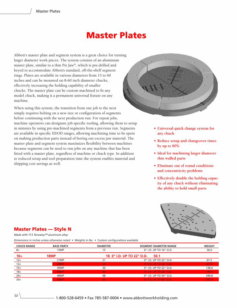
Master Plates
Abbott‘s master plate and segment system is a great choice for turning
larger diameter work pieces. The system consists of an aluminum
master plate, similar to a thin Pie Jaw®, which is pre-drilled and
keyed to accommodate Abbott’s standard, off-the-shelf segment
rings. Plates are available in various diameters from 15 to 60
inches and can be mounted on 8-60 inch diameter chucks,
effectively increasing the holding capability of smaller
chucks. The master plate can be custom machined to fit any
model chuck, making it a permanent universal fixture on any
machine.
When using this system, the transition from one job to the next
simply requires bolting on a new size or configuration of segments
before continuing with the next production run. For repeat jobs,
machine operators can designate job specific tooling, allowing them to setup
in minutes by using pre-machined segments from a previous run. Segments
are available in specific ID/OD ranges, allowing machining time to be spent
on making production parts instead of boring out excess jaw material. The
master plate and segment system maximizes flexibility between machines
because segments can be used to run jobs on any machine that has been
fitted with a master plate, regardless of machine or chuck type. In addition
to reduced setup and tool preparation time the system enables material and
shipping cost savings as well.
• Universal quick change system for
any chuck
• Reduce setup and changeover times
by up to 80%
• Ideal for machining larger diameter
thin walled parts
• Eliminate out of round conditions
and concentricity problems
• Effectively double the holding capac-
ity of any chuck without eliminating
the ability to hold small parts
Master Plates — Style NMade with 713 Tenzaloy™ aluminum alloy
Dimensions in inches unless otherwise noted • Weights in lbs. • Custom configurations available
CHUCK RAnGe BASe PART# DIAMeTeR SeGMenT DIAMeTeR RAnGe WeIGHT
8+ 15MP 15 0" I.D. UP TO 16" O.D. 36.0
10+ 18MP 18 0" I.D. UP TO 22" O.D. 50.112+ 21MP 21 0" I.D. UP TO 22" O.D. 67.5
12+ 24MP 24 0" I.D. UP TO 26" O.D. 87.9
15+ 30MP 30 0" I.D. UP TO 32" O.D. 138.6
18+ 36MP 36 0" I.D. UP TO 40" O.D. 198.9
24+ 48MP 48 0" I.D. UP TO 54" O.D. 349.8
30+ 60MP 60 0" I.D. UP TO 60" O.D. 547.2
31
Master Plates
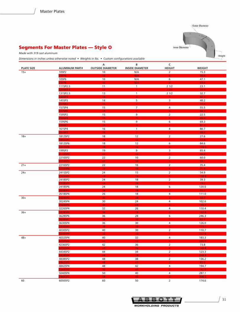
Segments For Master Plates — Style OMade with 319 cast aluminum
Dimensions in inches unless otherwise noted • Weights in lbs. • Custom configurations available
A B C
PLATe SIZe ALUMInUM PART# OUTSIDe DIAMeTeR InSIDe DIAMeTeR HeIGHT WeIGHT
15+ 10SP2 10 N/A 2 15.3
10SP4 10 N/A 4 30.6
10SP6 10 N/A 6 47.1
10SP8 10 N/A 8 63.6
111SP2.5 11 1 2 1/2 23.1
121SP2.5 12 1 2 1/2 27.9
131SP2.5 13 1 2 1/2 32.7
144SP3 14 4 3 42.3
145SP3 14 5 3 40.2
157SP2 15 7 2 27.6
157SP4 15 7 4 55.5
157SP6 15 7 6 84.3
159SP2 15 9 2 22.5
159SP4 15 9 4 45.6
159SP6 15 9 6 69.3
159SP7 15 9 7 81.3
161SP4 16 1 4 80.7
167SP3 16 7 3 48.8
18+ 1812SP2 18 12 2 27.6
1812SP4 18 12 4 55.8
1812SP6 18 12 6 84.6
1812SP8 18 12 8 114.3
199SP3 19 9 3 65.4
2112SP2 21 12 2 46.2
2210SP2 22 10 2 60.0
2210SP3 22 10 3 90.1
21+ 2216SP2 22 16 2 35.4
2216SP4 22 16 4 71.4
24+ 2415SP2 24 15 2 54.9
2415SP4 24 15 4 110.4
2418SP2 24 18 2 39.3
2418SP4 24 18 4 79.2
2418SP6 24 18 6 120.0
2618SP2 26 18 2 55.2
2618SP4 26 18 4 111.0
30+ 3024SP2 30 24 2 50.7
3024SP4 30 24 4 102.6
3024SP6 30 24 6 155.7
3226SP4 32 26 4 110.4
36+ 3628SP4 36 28 4 162.6
3628SP6 36 28 6 246.3
3630SP2 36 30 2 62.4
3630SP4 36 30 4 126.0
3830SP4 38 30 4 173.1
4030SP2 40 30 2 110.7
4030SP4 40 30 4 222.6
48+ 4032SP4 40 32 4 183.3
4232SP4 42 32 4 235.5
4236SP2 42 36 2 73.8
4236SP4 42 36 4 149.4
4434SP2 44 34 2 123.3
4434SP4 44 34 4 248.4
4838SP2 48 38 2 136.2
4842SP2 48 42 2 85.5
4842SP4 48 42 4 194.7
5040SP2 50 40 2 142.5
5040SP4 50 40 4 287.1
5440SP2 54 40 2 208.5
60 6050SP2 60 50 2 174.6
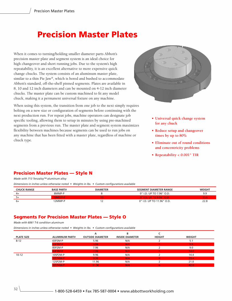
321-800-528-6459 • Fax 785-587-0004 • www.abbottworkholding.com
Precision Master Plates
When it comes to turning/holding smaller diameter parts Abbott’s
precision master plate and segment system is an ideal choice for
high changeover and short running jobs. Due to the system’s high
repeatability, it is an excellent alternative to more expensive quick
change chucks. The system consists of an aluminum master plate,
similar to a thin Pie Jaw®, which is bored and bushed to accommodate
Abbott’s standard, off-the-shelf pinned segments. Plates are available in
8, 10 and 12 inch diameters and can be mounted on 4-12 inch diameter
chucks. The master plate can be custom machined to fit any model
chuck, making it a permanent universal fixture on any machine.
When using this system, the transition from one job to the next simply requires
bolting on a new size or configuration of segments before continuing with the
next production run. For repeat jobs, machine operators can designate job
specific tooling, allowing them to setup in minutes by using pre-machined
segments from a previous run. The master plate and segment system maximizes
flexibility between machines because segments can be used to run jobs on
any machine that has been fitted with a master plate, regardless of machine or
chuck type.
Precision Master Plates
• Universal quick change system
for any chuck
• Reduce setup and changeover
times by up to 80%
• Eliminate out of round conditions
and concentricity problems
• Repeatability < 0.001" TIR
Precision Master Plates — Style NMade with 713 Tenzaloy™ aluminum alloy
Dimensions in inches unless otherwise noted • Weights in lbs. • Custom configurations available
CHUCK RAnGe BASe PART# DIAMeTeR SeGMenT DIAMeTeR RAnGe WeIGHT
4+ 8MMP-P 8 0" I.D. UP TO 7.96" O.D. 9.9
5+ 10MMP-P 10 0" I.D. UP TO 9.96" O.D. 15.6
6+ 12MMP-P 12 0" I.D. UP TO 11.96" O.D. 22.8
Segments For Precision Master Plates — Style OMade with 6061 T-6 condition aluminum
Dimensions in inches unless otherwise noted • Weights in lbs. • Custom configurations available
A B C
PLATe SIZe ALUMInUM PART# OUTSIDe DIAMeTeR InSIDe DIAMeTeR HeIGHT WeIGHT
8-12 6SP2M-P 5.96 N/A 2 5.1
6SP4M-P 5.96 N/A 4 9.9
8SP2M-P 7.96 N/A 2 9.0
8SP4M-P 7.96 N/A 4 18.0
10-12 10SP2M-P 9.96 N/A 2 14.4
10SP4M-P 9.96 N/A 4 28.4
12SP2M-P 11.96 N/A 2 21.0
12SP4M-P 11.96 N/A 4 42.0
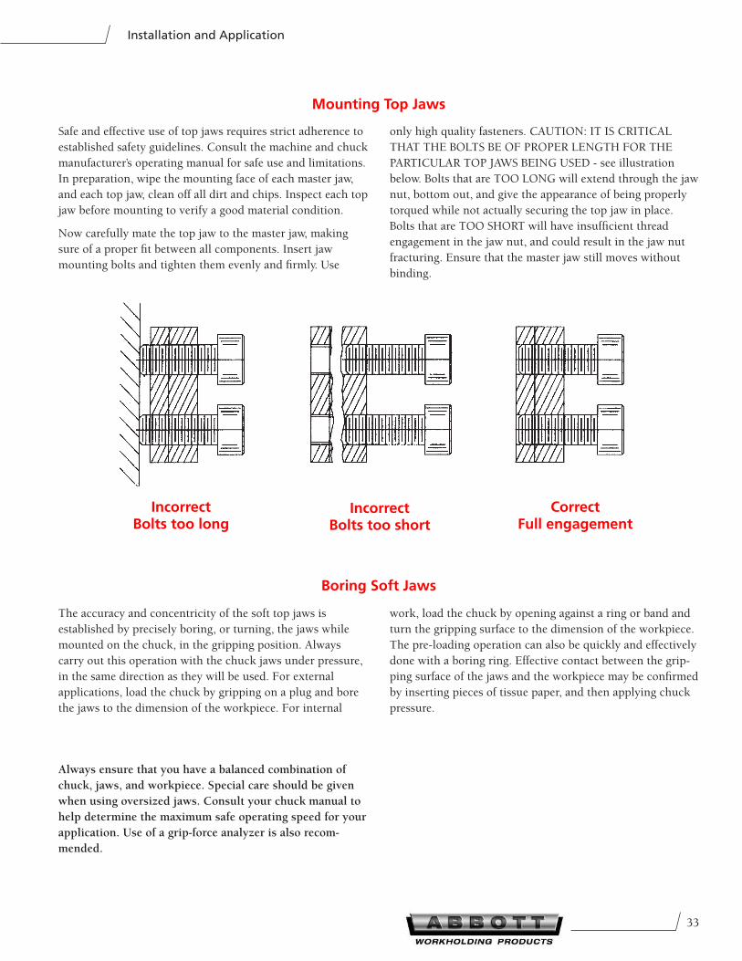
33
Installation and Application
Incorrect Bolts too long
Incorrect Bolts too short
Correct Full engagement
Always ensure that you have a balanced combination of
chuck, jaws, and workpiece. Special care should be given
when using oversized jaws. Consult your chuck manual to
help determine the maximum safe operating speed for your
application. Use of a grip-force analyzer is also recom-
mended.
Safe and effective use of top jaws requires strict adherence to
established safety guidelines. Consult the machine and chuck
manufacturer’s operating manual for safe use and limitations.
In preparation, wipe the mounting face of each master jaw,
and each top jaw, clean off all dirt and chips. Inspect each top
jaw before mounting to verify a good material condition.
Now carefully mate the top jaw to the master jaw, making
sure of a proper fit between all components. Insert jaw
mounting bolts and tighten them evenly and firmly. Use
only high quality fasteners. CAUTION: IT IS CRITICAL
THAT THE BOLTS BE OF PROPER LENGTH FOR THE
PARTICULAR TOP JAWS BEING USED - see illustration
below. Bolts that are TOO LONG will extend through the jaw
nut, bottom out, and give the appearance of being properly
torqued while not actually securing the top jaw in place.
Bolts that are TOO SHORT will have insufficient thread
engagement in the jaw nut, and could result in the jaw nut
fracturing. Ensure that the master jaw still moves without
binding.
Mounting Top Jaws
The accuracy and concentricity of the soft top jaws is
established by precisely boring, or turning, the jaws while
mounted on the chuck, in the gripping position. Always
carry out this operation with the chuck jaws under pressure,
in the same direction as they will be used. For external
applications, load the chuck by gripping on a plug and bore
the jaws to the dimension of the workpiece. For internal
work, load the chuck by opening against a ring or band and
turn the gripping surface to the dimension of the workpiece.
The pre-loading operation can also be quickly and effectively
done with a boring ring. Effective contact between the grip-
ping surface of the jaws and the workpiece may be confirmed
by inserting pieces of tissue paper, and then applying chuck
pressure.
Boring Soft Jaws
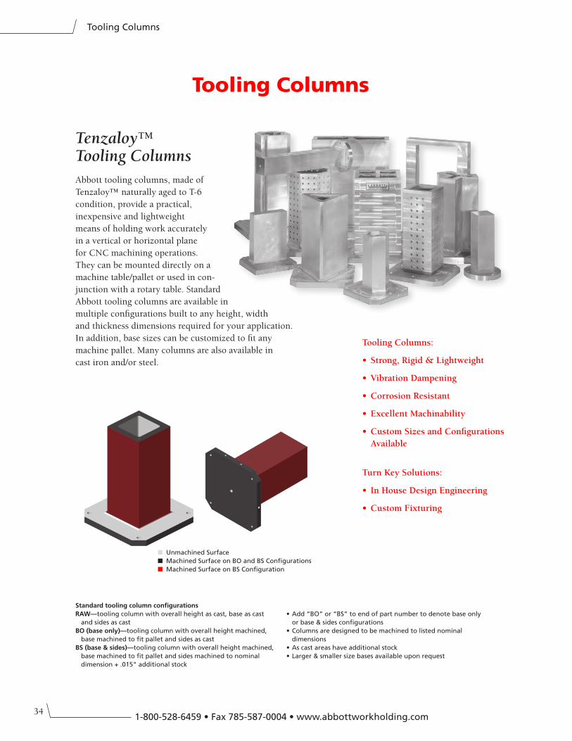
341-800-528-6459 • Fax 785-587-0004 • www.abbottworkholding.com
Tooling Columns
Tooling Columns
Abbott tooling columns, made of
Tenzaloy™ naturally aged to T-6
condition, provide a practical,
inexpensive and lightweight
means of holding work accurately
in a vertical or horizontal plane
for CNC machining operations.
They can be mounted directly on a
machine table/pallet or used in con-
junction with a rotary table. Standard
Abbott tooling columns are available in
multiple configurations built to any height, width
and thickness dimensions required for your application.
In addition, base sizes can be customized to fit any
machine pallet. Many columns are also available in
cast iron and/or steel.
Tooling Columns:
• Strong, Rigid & Lightweight
• Vibration Dampening
• Corrosion Resistant
• Excellent Machinability
• Custom Sizes and Configurations
Available
Turn Key Solutions:
• In House Design Engineering
• Custom Fixturing
Standard tooling column configurations
RAW—tooling column with overall height as cast, base as cast
and sides as cast
BO (base only)—tooling column with overall height machined,
base machined to fit pallet and sides as cast
BS (base & sides)—tooling column with overall height machined,
base machined to fit pallet and sides machined to nominal
dimension + .015" additional stock
• Add “BO” or “BS” to end of part number to denote base only
or base & sides configurations
• Columns are designed to be machined to listed nominal
dimensions
• As cast areas have additional stock
• Larger & smaller size bases available upon request
Tenzaloy™ Tooling Columns
■ Unmachined Surface
■ Machined Surface on BO and BS Configurations
■ Machined Surface on BS Configuration
35
Tooling Columns
High Strength
Tenzaloy™ is a high-strength aluminum casting alloy
that has tensile yield and elongation properties equiva-
lent to the common heat treated alloys such as 195T6,
355T6 and 319T6. The impact strength of Tenzaloy™ is
greater than any of these alloys, and in several instances
the elongation is higher.
Tenzaloy™ attains its strength by a natural aging
process that gradually takes place at room temperature.
The typical properties are reached after 10-14 days, and
when testing for specification purposes, a 21-day period
is used. Some slight further aging and strengthening
takes place up to six months, at which time the alloy is
stable and no further change of any kind takes place.
Test bars held for six years at room temperature have
shown that the properties remain constant.
Elimination of Heat Treatment
Because Tenzaloy™ is self-aging, no heat treatment is
required. The first and most obvious advantage gained
is the saving of the cost of the treatment and the extra
freight often involved if the heat treating is being done
outside the foundry. The process of heat treatment is
far from a fool-proof operation, and is subject to many
errors and failures (both man and machine).
The solution heat treatment is carried out at as high
a temperature as possible for maximum efficiency.
This temperature is just below the melting point, and
a common cause of difficulty is overheating due to
faulty temperature control or hot spots in the furnace.
This overheating often results in warped, cracked and,
occasionally, melted castings, which are then a complete
loss.
The quenching operation which follows solution heat
treatment can cause substantial problems with regard
to warpage and cracking. When distortion occurs, the
castings must be straightened—a troublesome operation
which must be performed within a short time after
quenching, while the castings are soft.
Stress-free, Full-strength Castings
If Tenzaloy™ is given a simple heat treatment of six
hours at 468˚ C. and allowed to air cool (not quenched)
it will age normally and result in a stress-free, full-
strength casting. This is not possible with any heat
treated alloy.
All castings of any alloy will contain internal stresses as
a result of the casting process. The solution heat treat-
ment cycle of the heat treated alloys will eliminate these
cast stresses, but the quenching operation introduced
much greater ones. Conventional T6 aging treatments
do not relieve these stresses. Aging treatments which do
relieve these quenching stresses (such as T71) result in
inferior properties. The cast stresses can be relieved by
a simple, one-step aging treatment (T5) but here again
inferior properties result.
Thus, through the use of Tenzaloy™, it is possible to
obtain castings that have their full strength and yet
are stress-free. This is important for uses where close
dimensional and straightness tolerances must be main-
tained, especially where the castings are extensively
machined.
Dimensional Stability
Tenzaloy™ is dimensionally stable and does not grow or
increase in size as do the heat treatable alloys. Actually,
fully aged Tenzaloy™ shows a very slight decrease in
length of less than 0.025mm per 25.4mm. In contrast to
this, heat treated alloys can increase in size as much as
0.10% to 0.15% (0.025mm to 0.038mm per 25.4mm).
Machinability
The machinability of Tenzaloy™ is exceptionally
good—equal to the very best of aluminum alloys, such
as the aluminum-magnesium types. The machinability
is greater than the common aluminum-copper or
aluminum-silicon heat-treatable alloys. Often it will be
found that several machining steps can be eliminated
because Tenzaloy™ attains a fine finish with fewer
cuts. Also, Tenzaloy™ may be machined at the highest
possible speeds. As can be seen from the mechanical
property tables and aging curves, immediately after cast-
ing, the alloy is relatively soft and ductile. If machined
at this point the castings will give the impression of
being gummy. Even though many machining operations
are performed soon after casting, best results will be
obtained if the castings are allowed to age about five
days. Although the typical properties are not reached
until ten to fourteen days, sufficient hardening will
have taken place in five days to materially improve
machinability.
Tenzaloy™ is readily polished to a high luster with a
silvery-white color. The time when the ability to be
polished will be best will vary somewhat with the pref-
erences of the polisher. One who prefers a soft metal,
easily smeared, will like to polish soon after casting.
One who prefers a hard metal easily cut, will prefer a
casting that has aged and hardened.
Anodizing
Tenzaloy™ can be readily anodized by standard
procedures and will produce a white color superior to
alloys containing copper and/or silicon. The anodized
coating may be dyed any available color. It should be
emphasized that the surfaces of sand castings in any
alloy are prone toward porosity of many kinds, and
that if coloring is being considered, the surfaces must
contain a minimum of porosity for satisfactory dye
application.
Brazing
Because of its high melting range of 607-652˚ C.,
Tenzaloy™ is one of the few casting alloys which can
be brazed at temperatures of 552-607˚ C. Conventional
techniques may be used, such as oven, torch or flux-
bath dip methods. Tenzaloy™ can be brazed to itself, to
extruded aluminum sections, or to other forms of the
proper alloys.
Corrosion Resistance
Tenzaloy™ has excellent corrosion resistance,
equivalent to the aluminum-silicon alloys. Tenzaloy™
compares favorably with other high strength alloys
in that the alloy is not susceptible to acceleration of
corrosion by stress (below 80% of the yield strength)
nor to stress corrosion cracking. The alloy exhibited a
negligible loss of mechanical properties after immersion
in aerated 3% water solution of sodium chloride for
ninety days, and the small surface attack that was
present was found to be uniform without pitting. This
uniformity of resistance is not encountered with the
aluminum-silicon alloys commonly considered to be
corrosion resistant.
713 (Tenzaloy™)
General Advantages and Characteristics
General Applications
Since Tenzaloy™ has mechanical properties
equivalent to the common heat-treated
alloys, it may be substituted in applications
where a heat-treated alloy is presently being used.
Tenzaloy™ is used in any high strength application
where load carrying capacity and impact strength
is desired. This may be almost any type of casting
of this nature, including frames, brackets, levers,
bases, housing, heavy duty fan blades, etc. The high
machinability and fine finishes obtainable have been
sufficient reason alone for the use of Tenzaloy™ in
many instances.
Tenzaloy™ has often been used for the production
of large, high strength castings where heat-treated
alloys could not be used because of the lack of
sufficiently large heat treating facilities.
The dimensional stability, ease of machining, and the
ability to make stress-free castings is of great value
in applications where strength and close tolerances
are essential, such as instrument frames, housings
and components.
The ability to be brazed has resulted in the
widespread use of Tenzaloy™ (cast by all methods)
for such things as radar wave guide, plumbing and
gasoline pump fittings.
The ease of polishing and brilliant surface obtainable
make it ideal for castings requiring this type of
finish.
Tenzaloy™ has been successfully used in
applications involving pressure tightness. In such
applications, as with all aluminum alloys, particular
attention must be given to gating and risering to
insure proper feeding of the casting.
Tenzaloy™ has replaced malleable iron in many
applications, often with no changes in design. In
other instances, the change has been made with but
minor changes in design to compensate for the lower
modulus of elasticity of aluminum as compared to
iron base alloys. Many small brackets, levers, and
particularly anything that must be carried, lifted,
or shipped long distances, can be advantageously
converted to Tenzaloy™ alloy.
Tenzaloy™ is most easily welded by the insert gas
shielded arc process using 43S or similar filler rod.
By this means, excellent welds may be obtained
between Tenzaloy™ components and between
Tenzaloy™ and most other aluminum shapes, cast
or wrought. High strength welds can be obtained
with the use of Tenzaloy™ filler, but greater skill is
necessary.
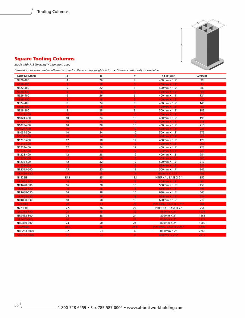
361-800-528-6459 • Fax 785-587-0004 • www.abbottworkholding.com
Tooling Columns
Square Tooling ColumnsMade with 713 Tenzaloy™ aluminum alloy
Dimensions in inches unless otherwise noted • Raw casting weights in lbs. • Custom configurations available
PART nUMBeR A B C BASe SIZe WeIGHT
N426-400 4 26 4 400mm X 1.5" 99
N518-400 5 18 5 400mm X 1.5" 79
N522-400 5 22 5 400mm X 1.5" 86
N618-400 6 18 6 400mm X 1.5" 99
N626-400 6 26 6 400mm X 1.5" 124
N818-400 8 18 8 400mm X 1.5" 120
N824-400 8 24 8 400mm X 1.5" 146
N828-400 8 28 8 400mm X 1.5" 163
N828-500 8 28 8 500mm X 1.5" 189
N1018-400 10 18 10 400mm X 1.5" 153
N1024-400 10 24 10 400mm X 1.5" 190
N1024-500 10 24 10 500mm X 1.5" 216
N1028-400 10 28 10 400mm X 1.5" 215
N1028-500 10 28 10 500mm X 1.5" 241
N1034-500 10 34 10 500mm X 1.5" 279
N1034-630 10 34 10 630mm X 1.5" 320
N1218-400 12 18 12 400mm X 1.5" 178
N1218-500 12 18 12 500mm X 1.5" 203
N1224-400 12 24 12 400mm X 1.5" 223
N1224-500 12 24 12 500mm X 1.5" 249
N1228-400 12 28 12 400mm X 1.5" 254
N1228-500 12 28 12 500mm X 1.5" 280
N1232-500 12 32 12 500mm X 1.5" 310
N1232-630 12 32 12 630mm X 1.5" 353
NR1325-500 13 25 13 500mm X 1.5" 342
NR1430-630 14 30 14 630mm X 1.75" 485
N1525IB 15.1 25 15.1 INTERNAL BASE X 2" 352
NR1624-500 16 24 16 500mm X 1.5" 401
NR1628-500 16 28 16 500mm X 1.5" 458
NR1628-630 16 28 16 630mm X 1.5" 499
NR1638-630 16 38 16 630mm X 1.5" 643
NR1828-630 18 28 18 630mm X 1.5" 554
NR1838-630 18 38 18 630mm X 1.5" 718
N2033IB 20 33 20 INTERNAL BASE X 1.75" 508
N2236IB 22 36 22 INTERNAL BASE X 2" 754
NR2238-630 22 38 22 630mm X 2" 1076
NR2438-800 24 38 24 800mm X 2" 1261
NR2442-800 24 42 24 800mm X 2" 1374
NR2450-800 24 50 24 800mm X 2" 1600
NR2946IB 28.8 46 28.8 INTERNAL BASE X 2.25" 1899
NR3253-1000 32 53 32 1000mm X 2" 2765
NR3753-1000 37 53 37 1000mm X 2.5" 2517
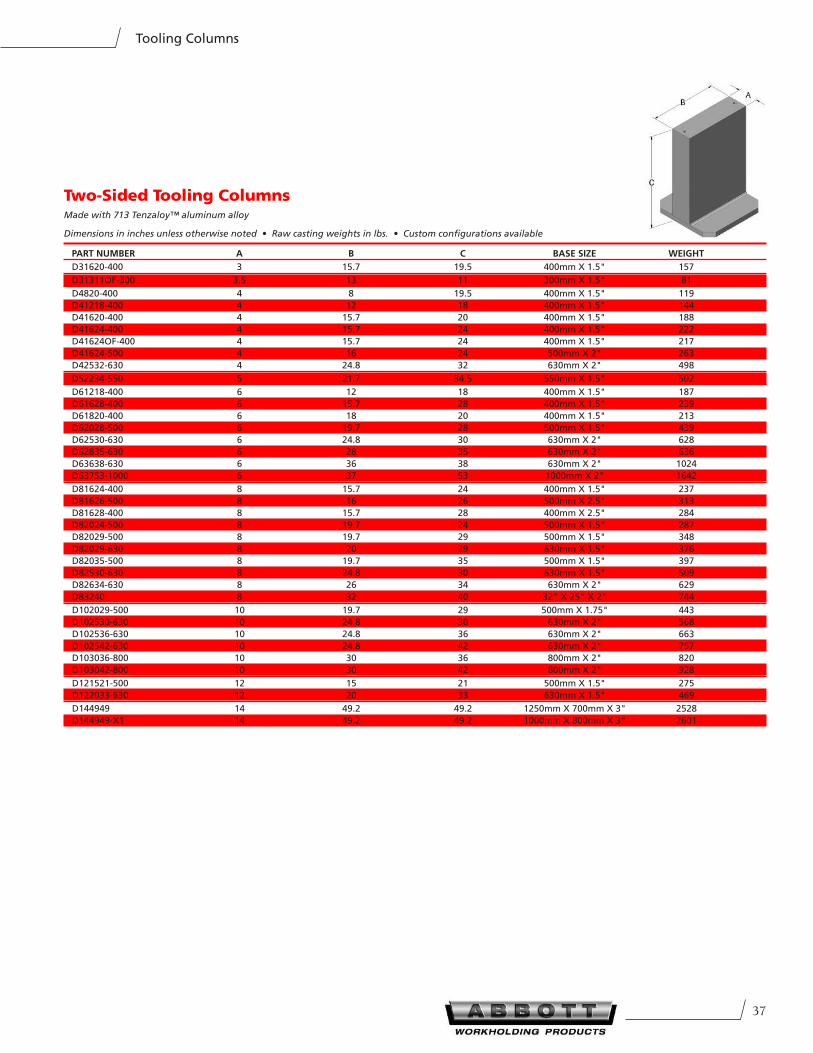
37
Tooling Columns
Two-Sided Tooling ColumnsMade with 713 Tenzaloy™ aluminum alloy
Dimensions in inches unless otherwise noted • Raw casting weights in lbs. • Custom configurations available
PART nUMBeR A B C BASe SIZe WeIGHT
D31620-400 3 15.7 19.5 400mm X 1.5" 157
D31311OF-300 3.5 13 11 300mm X 1.5" 81
D4820-400 4 8 19.5 400mm X 1.5" 119
D41218-400 4 12 18 400mm X 1.5" 144
D41620-400 4 15.7 20 400mm X 1.5" 188
D41624-400 4 15.7 24 400mm X 1.5" 222
D41624OF-400 4 15.7 24 400mm X 1.5" 217
D41624-500 4 16 24 500mm X 2" 263
D42532-630 4 24.8 32 630mm X 2" 498
D52234-550 5 21.7 34.5 550mm X 1.5" 502
D61218-400 6 12 18 400mm X 1.5" 187
D61628-400 6 15.7 28 400mm X 1.5" 239
D61820-400 6 18 20 400mm X 1.5" 213
D62028-500 6 19.7 28 500mm X 1.5" 439
D62530-630 6 24.8 30 630mm X 2" 628
D62835-630 6 28 35 630mm X 2" 636
D63638-630 6 36 38 630mm X 2" 1024
D63753-1000 6 37 53 1000mm X 2" 1642
D81624-400 8 15.7 24 400mm X 1.5" 237
D81626-500 8 16 26 500mm X 2.5" 313
D81628-400 8 15.7 28 400mm X 2.5" 284
D82024-500 8 19.7 24 500mm X 1.5" 287
D82029-500 8 19.7 29 500mm X 1.5" 348
D82029-630 8 20 29 630mm X 1.5" 376
D82035-500 8 19.7 35 500mm X 1.5" 397
D82530-630 8 24.8 30 630mm X 1.5" 509
D82634-630 8 26 34 630mm X 2" 629
D83240 8 32 40 32" X 25" X 2" 744
D102029-500 10 19.7 29 500mm X 1.75" 443
D102530-630 10 24.8 30 630mm X 2" 568
D102536-630 10 24.8 36 630mm X 2" 663
D102542-630 10 24.8 42 630mm X 2" 757
D103036-800 10 30 36 800mm X 2" 820
D103042-800 10 30 42 800mm X 2" 928
D121521-500 12 15 21 500mm X 1.5" 275
D122033-630 12 20 33 630mm X 1.5" 469
D144949 14 49.2 49.2 1250mm X 700mm X 3" 2528
D144949-X1 14 49.2 49.2 1000mm X 800mm X 3" 2601
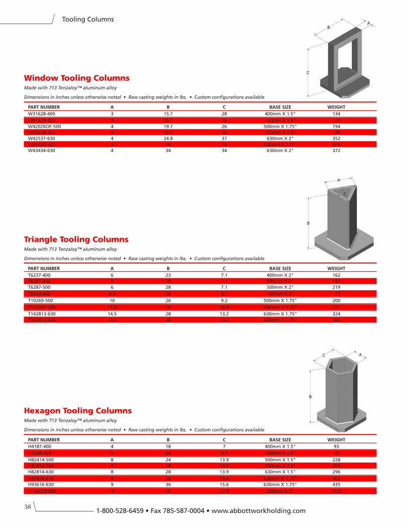
381-800-528-6459 • Fax 785-587-0004 • www.abbottworkholding.com
Tooling Columns
Hexagon Tooling ColumnsMade with 713 Tenzaloy™ aluminum alloy
Dimensions in inches unless otherwise noted • Raw casting weights in lbs. • Custom configurations available
PART nUMBeR A B C BASe SIZe WeIGHT
H4187-400 4 18 7 400mm X 1.5" 93
H5249-400 5 24 8.7 400mm X 1.5" 151
H82414-500 8 24 13.9 500mm X 1.5" 228
H82814-500 8 28 13.9 500mm X 1.5" 255
H82814-630 8 28 13.9 630mm X 1.5" 296
H92816-630 9 28 15.6 630mm X 1.75" 365
H93616-630 9 36 15.6 630mm X 1.75" 435
H165028-800 16 50 27.8 800mm X 2" 1533
Window Tooling ColumnsMade with 713 Tenzaloy™ aluminum alloy
Dimensions in inches unless otherwise noted • Raw casting weights in lbs. • Custom configurations available
PART nUMBeR A B C BASe SIZe WeIGHT
W31628-400 3 15.7 28 400mm X 1.5" 134
W41620-400 4 15.7 20 400mm X 1.5" 144
W42026OF-500 4 19.7 26 500mm X 1.75" 194
W42029-500 4 19.7 29 500mm X 1.5" 196
W42537-630 4 24.8 37 630mm X 2" 352
W42633-500 4 26 33 500mm X 2.25" 346
W43434-630 4 34 34 630mm X 2" 372
Triangle Tooling ColumnsMade with 713 Tenzaloy™ aluminum alloy
Dimensions in inches unless otherwise noted • Raw casting weights in lbs. • Custom configurations available
PART nUMBeR A B C BASe SIZe WeIGHT
T6237-400 6 23 7.1 400mm X 2" 162
T6287-400 6 28 7.1 400mm X 2" 185
T6287-500 6 28 7.1 500mm X 2" 219
T8288-400 8.4 28 8.1 400mm X 2" 177
T10269-500 10 26 9.2 500mm X 1.75" 200
T122611-500 11.8 26 10.9 500mm X 1.75" 227
T142813-630 14.5 28 13.2 630mm X 1.75" 324
T143813-630 14.5 38 13.2 630mm X 1.75" 395
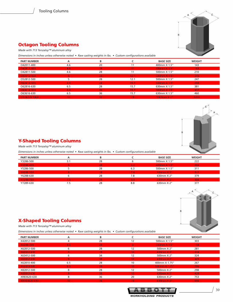
39
Tooling Columns
Octagon Tooling ColumnsMade with 713 Tenzaloy™ aluminum alloy
Dimensions in inches unless otherwise noted • Raw casting weights in lbs. • Custom configurations available
PART nUMBeR A B C BASe SIZe WeIGHT
O42011-400 4.6 20 11 400mm X 1.5" 143
O42811-400 4.6 28 11 400mm X 1.5" 183
O42811-500 4.6 28 11 500mm X 1.5" 210
O52312-500 5 23 12.1 500mm X 1.5" 215
O52812-500 5 28 12.1 500mm X 1.5" 247
O62416-500 6.5 24 15.7 500mm X 1.5" 298
O62816-630 6.5 28 15.7 630mm X 1.5" 381
O63616-500 6.5 36 15.7 500mm X 1.5" 417
O63616-630 6.5 36 15.7 630mm X 1.5" 460
O124229-1000 12 42 29 1000mm X 2" 1203
X-Shaped Tooling ColumnsMade with 713 Tenzaloy™ aluminum alloy
Dimensions in inches unless otherwise noted • Raw casting weights in lbs. • Custom configurations available
PART nUMBeR A B C BASe SIZe WeIGHT
X42812-500 4 28 12 500mm X 1.5" 303
X4248-300 4.5 24 8 300mm X 1.5" 158
X62812-500 6 28 12 500mm X 2" 281
X62812-630 6 28 12 630mm X 2" 334
X63412-500 6 34 12 500mm X 2" 324
X63812-630 6 38 12 630mm X 2" 405
X62810-400 6.5 28 10 400mm X 1.75" 267
X62810-500 6.5 28 10 500mm X 1.75" 296
X82812-500 8 28 12 500mm X 2" 298
X83812-630 8 38 12 630mm X 2" 428
XR83620-630 8 36 20 630mm X 2" 753
XR103620-630 10 36 20 630mm X 2" 696
Y-Shaped Tooling ColumnsMade with 713 Tenzaloy™ aluminum alloy
Dimensions in inches unless otherwise noted • Raw casting weights in lbs. • Custom configurations available
PART nUMBeR A B C BASe SIZe WeIGHT
Y3286-500 3.1 28 6 500mm X 1.5" 222
Y5286-400 5 28 6.3 400mm X 1.5" 286
Y5286-500 5 28 6.3 500mm X 1.5" 311
Y6288-500 6 28 7.8 500mm X 2" 327
Y6288-630 6 28 7.8 630mm X 2" 379
Y7289-500 7.5 28 8.8 500mm X 2" 308
Y7289-630 7.5 28 8.8 630mm X 2" 377
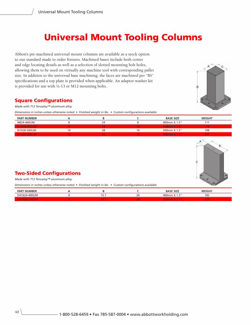
401-800-528-6459 • Fax 785-587-0004 • www.abbottworkholding.com
Universal Mount Tooling Columns
Universal Mount Tooling Columns
Square ConfigurationsMade with 713 Tenzaloy™ aluminum alloy
Dimensions in inches unless otherwise noted • Finished weight in lbs. • Custom configurations available
PART nUMBeR A B C BASe SIZe WeIGHT
N824-400UM 8 24 8 400mm X 1.5" 117
N1028-400UM 10 28 10 400mm X 1.5" 178
N1028-500UM 10 28 10 500mm X 1.5" 198
N1232-500UM 12 32 12 500mm X 1.5" 257
Abbott’s pre-machined universal mount columns are available as a stock option
to our standard made to order fixtures. Machined bases include both center
and edge locating details as well as a selection of slotted mounting bolt holes,
allowing them to be used on virtually any machine tool with corresponding pallet
size. In addition to the universal base machining, the faces are machined per “BS”
specifications and a top plate is provided when applicable. An adaptor washer kit
is provided for use with ½-13 or M12 mounting bolts.
Two-Sided ConfigurationsMade with 713 Tenzaloy™ aluminum alloy
Dimensions in inches unless otherwise noted • Finished weight in lbs. • Custom configurations available
PART nUMBeR A B C BASe SIZe WeIGHT
D41624-400UM 4 15.7 24 400mm X 1.5" 182
D62028-500UM 6 19.7 28 500mm X 1.5" 379
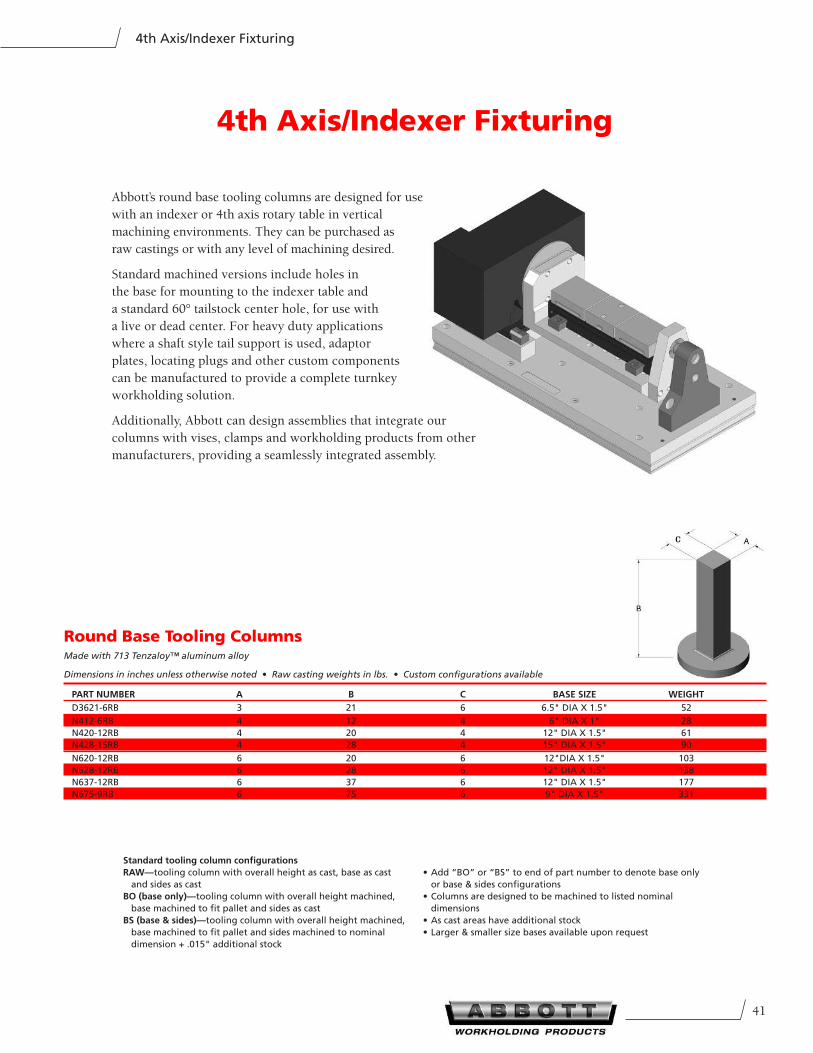
41
4th Axis/Indexer Fixturing
4th Axis/Indexer Fixturing
Abbott’s round base tooling columns are designed for use
with an indexer or 4th axis rotary table in vertical
machining environments. They can be purchased as
raw castings or with any level of machining desired.
Standard machined versions include holes in
the base for mounting to the indexer table and
a standard 60° tailstock center hole, for use with
a live or dead center. For heavy duty applications
where a shaft style tail support is used, adaptor
plates, locating plugs and other custom components
can be manufactured to provide a complete turnkey
workholding solution.
Additionally, Abbott can design assemblies that integrate our
columns with vises, clamps and workholding products from other
manufacturers, providing a seamlessly integrated assembly.
Standard tooling column configurations
RAW—tooling column with overall height as cast, base as cast
and sides as cast
BO (base only)—tooling column with overall height machined,
base machined to fit pallet and sides as cast
BS (base & sides)—tooling column with overall height machined,
base machined to fit pallet and sides machined to nominal
dimension + .015" additional stock
• Add “BO” or “BS” to end of part number to denote base only
or base & sides configurations
• Columns are designed to be machined to listed nominal
dimensions
• As cast areas have additional stock
• Larger & smaller size bases available upon request
Round Base Tooling ColumnsMade with 713 Tenzaloy™ aluminum alloy
Dimensions in inches unless otherwise noted • Raw casting weights in lbs. • Custom configurations available
PART nUMBeR A B C BASe SIZe WeIGHT
D3621-6RB 3 21 6 6.5" DIA X 1.5" 52
N412-6RB 4 12 4 6" DIA X 1" 28
N420-12RB 4 20 4 12" DIA X 1.5" 61
N428-15RB 4 28 4 15" DIA X 1.5" 90
N620-12RB 6 20 6 12"DIA X 1.5" 103
N628-12RB 6 28 6 12" DIA X 1.5" 138
N637-12RB 6 37 6 12" DIA X 1.5" 177
N675-9RB 6 75 6 9" DIA X 1.5" 331
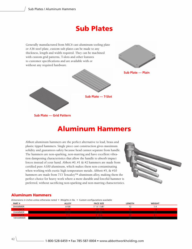
421-800-528-6459 • Fax 785-587-0004 • www.abbottworkholding.com
Sub Plates / Aluminum Hammers
Abbott aluminum hammers are the perfect alternative to lead, brass and
plastic tipped hammers. Single piece cast construction gives maximum
solidity and guarantees safety because head cannot separate from handle.
The hammers are non-sparking, non-marring and have excellent vibra-
tion dampening characteristics that allow the handle to absorb impact
forces instead of your hand. Abbott #0, #1 & #2 hammers are made from
certified pure A100 aluminum, which makes them non-contaminating
when working with exotic high temperature metals. Abbott #5, & #10
hammers are made from 713 Tenzaloy™ aluminum alloy, making them the
perfect choice for heavy work where a more durable and forceful hammer is
preferred, without sacrificing non-sparking and non-marring characteristics.
Aluminum Hammers
Sub Plate — Plain
Sub Plate — T-Slot
Sub Plate — Grid Pattern
Generally manufactured from MIC6 cast aluminum tooling plate
or A36 steel plate, custom sub plates can be made to any
thickness, length and width required. They can be machined
with custom grid patterns, T-slots and other features
to customer specifications and are available with or
without any required hardware.
Sub Plates
Aluminum HammersDimensions in inches unless otherwise noted • Weights in lbs. • Custom configurations available
PART # ALLOY FACe SIZe LenGTH WeIGHT
0HAMMER A100 1" X 1 5/8" 12 1.4
1HAMMER A100 1 5/8" DIA 12 1.8
2HAMMER A100 2" DIA 13 3.3
5HAMMER 713 3" DIA 22 9.1
10HAMMER 713 4" DIA 29 16.3
43
Warranty
ABBOTT warrants that its goods
will conform to the description
and specifications as set forth in the
latest ABBOTT product catalog or in
purchase orders received and accepted
by ABBOTT.
ABBOTT further warrants that the
goods shall be free from defects in
material and workmanship. Minor
surface porosity is not to be considered
a defect for purposes of this warranty.
This warranty is expressly made in
lieu of any and all other warranties,
expressed or implied, including the
warranties of merchantability and
fitness. There are no other warranties
which extend beyond the description
in this agreement.
Limitations of Remedies
The exclusive remedy in the event that
any of the goods do not conform to
the description of ABBOTT’s standard
warranty shall be replacement or repair
of the goods at the option of ABBOTT.
Except as otherwise agreed upon
herein, ABBOTT shall not be liable
for special or consequential damages,
such as, but not limited to, damage or
loss of other property or equipment,
loss of profits or revenue, loss of use
of power system, cost of capital, cost
of purchased or replacement parts or
claims of third persons or parties.
The remedies set forth herein are
exclusive and the liability of ABBOTT
with respect to goods sold or ancillary
claims arising from the use of any
goods manufactured by ABBOTT,
whether such remedies are based on
contract, tort, strict liability or other
warranty theories, shall not, except as
expressly provided for herein, exceed
the price of the goods or the part or
portion of the goods on which such
liability or claim is based.
All goods claimed to be non-
conforming must be shipped to
MANUFACTURER’s Manhattan,
Kansas plant at MANUFACTURER’s
expense. Such goods will be repaired
or replaced within a reasonable time.
ABBOTT’s acceptance of any goods
so shipped shall not be deemed an
admission that the goods are non-con-
forming, and if ABBOTT finds that any
goods returned are not defective, such
goods will be re-shipped to purchaser
and purchaser will be charged all ship-
ping charges incurred by ABBOTT.
Return Policy
Standard Chuck Jaws
All standard chuck jaws may be
returned to Abbott within 6 months of
invoice/shipping date.
After 6 months from invoice date,
goods may not be returned unless
special circumstances exist and return
is approved by Abbott.
All returned goods must be assigned an
RMA number by Abbott prior to being
returned. All returned goods must be
inspected by Abbott and accepted into
inventory prior to credit being applied.
All returned goods are subject to a 15%
restocking fee unless Abbott is at fault
due to inaccurate order processing or
incorrect manufacturing.
Made to order chuck jaws,
master plates and fixtures
All made to order products, including
special chuck jaws, master plates and
fixtures, may not be returned unless
special circumstances exist and return
is approved by Abbott.
Warranty
430 McCall Road
Manhattan, Kansas 66502
United States
Office 785.776.8555
Toll Free 800.528.6459
Fax 785.587.0004
www.abbottworkholding.com
©2013 Abbott Workholding Products 09/13Made in U.S.A.Since 1954