Embed Size (px)
Citation preview
7/21/2019 The Civil Engineering Specification for the Water Industry 7th
http://slidepdf.com/reader/full/the-civil-engineering-specification-for-the-water-industry-7th 1/176Licensed to HHI Co. LTD. 2013-08-20. Any form of reproduction and redistribution are atrictly prohibited.
ivil
Engineering
Specification
for
the
Water
Industry
th
Edition
UKWIR Ltd

7/21/2019 The Civil Engineering Specification for the Water Industry 7th
http://slidepdf.com/reader/full/the-civil-engineering-specification-for-the-water-industry-7th 2/176Licensed to HHI Co. LTD. 2013-08-20. Any form of reproduction and redistribution are atrictly prohibited.
7/21/2019 The Civil Engineering Specification for the Water Industry 7th
http://slidepdf.com/reader/full/the-civil-engineering-specification-for-the-water-industry-7th 3/176Licensed to HHI Co. LTD. 2013-08-20. Any form of reproduction and redistribution are atrictly prohibited.
CIVIL ENGINEERING SPECIFICATION FOR THE WATER INDUSTRY
SEVENTH EDITION)
MARCH 2011
Published by WRc pic
Frankland Road
Blagrove
Swindon
Wiltshire
SN 8YF
on behalf
of
UK Water Industry Research Ltd
1
Queen Anne s Gate
London
SW1H 9BT

7/21/2019 The Civil Engineering Specification for the Water Industry 7th
http://slidepdf.com/reader/full/the-civil-engineering-specification-for-the-water-industry-7th 4/176Licensed to HHI Co. LTD. 2013-08-20. Any form of reproduction and redistribution are atrictly prohibited.
7/21/2019 The Civil Engineering Specification for the Water Industry 7th
http://slidepdf.com/reader/full/the-civil-engineering-specification-for-the-water-industry-7th 5/176Licensed to HHI Co. LTD. 2013-08-20. Any form of reproduction and redistribution are atrictly prohibited.
Copyright
The contents
of
th is document are subject to copyright and all rights are reserv
ed
. No part
of
this document may
be reproduced, stored in a retrieval system
or
transmitted, in any form or by any means electronic, mechanical,
recording or otherwise, without the prior written consent of the copyright owner.
© UK Water Industry Research Ltd, March 20
ISBN 978 1898920 687
Feedback rrangements
Technical queries should be referred to: CESWI Technica l Secretary, WRc pic, Frankland Road, Blagrove,
Swindon, Wiltshire, SN5 8YF
Tel: 44 0) 1793 865105
Fax: +
44
0) 1793 865001
Web: http://ceswi.wrcplc.co.uk
Further Copies
Further copies can be obtained from: WRc pic, Frankland Road, Blagrove, Swindon, Wi ltshire, SN5 8YF
Tel:
44
0) 1793 865012
Fax: +
44 0) 1793 514562
Email: [email protected]
Web: www.webookshop.com

7/21/2019 The Civil Engineering Specification for the Water Industry 7th
http://slidepdf.com/reader/full/the-civil-engineering-specification-for-the-water-industry-7th 6/176Licensed to HHI Co. LTD. 2013-08-20. Any form of reproduction and redistribution are atrictly prohibited.
7/21/2019 The Civil Engineering Specification for the Water Industry 7th
http://slidepdf.com/reader/full/the-civil-engineering-specification-for-the-water-industry-7th 7/176Licensed to HHI Co. LTD. 2013-08-20. Any form of reproduction and redistribution are atrictly prohibited.
Civil Engineering Specification for the Water I
ndustry
7
t Ed
ition
FOREWORD SEVENTH EDITION
The Civil Engineering Specification for the Water Industry (CESWI) was first published
in
July 1978, followed by
second, third, fourth, fifth and sixth editions in August 1984, May 1989, October 1993, Ju ly 1998 and June 2004,
respectively. It has become the
standard document for civil engineering contracts let
by
the Water Undertakers
and
Sewerage Undertakers in England, Wales and Scotland.
In 201
0, a national survey was undertaken to elicit comments on how the si
xth
edition
of
the Specification might be
improve
d.
Announcements were subsequently made
in
appropriate publications and comments were invited from the
Water Industry.
In redrafting CESWI, the Working Group adhered to
the
principles used in
the
earlier editions; in particular, that the
document should be performance based and that, in letting any contract for civil engineering works , the several
documents that form the Contract are to be taken as being mutually explanatory of one another. CESWI does not,
therefore, repeat other nationally accepted Specifications, rather it refers to them in the relevant Notes for Guidance
and in the Appendices.
As in the previous edition, the seventh edition is generic in form and not tied to any particular form
of
Contract or
method
of
valuation.
As there is no consistent terminology across the Conditions of Contract most commonly used
in
the Water Industry, the
term Client has been adopted, as a classification independent of the specific conditions of contract, for the terms
Employer, Authority and Purchaser. Similarly, wherever possible, the seventh edition has been re-worded to remove
specific reference to the Contractor or Contract Administrator
,
in
order to make
the
seventh edition more flexible with
respect to the many al liancing, joint ventures, and other contracting entities that now carry out work for the Water
Industry.
There is no reference in the Specification to satisfy legislation. This follows the general principle that the Works are to
be
designed and constructed to comply with all relevant Statutes. A number
of
Notes for Guidance have been included,
where appropriate.
As with previous
ed
itions, it is envisaged that additiona l Clauses will be added to provide for individual requirements
and the inclusion
of
such Clauses has been allowed for in the system
of
numbering, which should be followed when
adding any additional Clauses in order to maintain consistency of presentation. This will be further facilitated by the
availability of an electronic version (see www.wrcplc.co.uk/ceswi).
CESWI 7 is a comprehensive, universal and relevant Specification for the Water Industry. It is compatible with most
nationally produced Engineering Forms
of
Contract.
It
remains a valuable foundation document for use throughout the
UK
Water Industry.
UKWIR Ltd
7/21/2019 The Civil Engineering Specification for the Water Industry 7th
http://slidepdf.com/reader/full/the-civil-engineering-specification-for-the-water-industry-7th 8/176Licensed to HHI Co. LTD. 2013-08-20. Any form of reproduction and redistribution are atrictly prohibited.
Civil Engineering Specification for the Water Industry 7
h Edition
The Specification was reviewed and redrafted by the following Working Group:
Mike Smith
Chairman)
Santoro Salvatore
Les Gonzalez
Dominic Wall
Mick Abbott
lain MacDonald
Mike Fairlamb
John Foster
Kate Harrison
r
ian Spencer
Jack McCarey
Don Ridgers
Duncan McKinley-Bourne
Brian Spark
Stuart Lewis
Brian Smith
Sarah Wilcox
Technical Secretary)
Jo Hulance
Nick Orman
Julia Trew
HuwWi
lliams
Cover designed by WRc pic.
2
Bristol Water
Anglian Water
Dwr Cymru
Dwr Cymru
Northumbrian Water
Scotti
sh
Water
Severn Trent Water
Severn Trent Water
South East Water
Southern Water
South West Water
Thames Water
United Utilities
Water UK
Wessex Water
Yorksh ire Water
WRcplc
WRc pic
WRcplc
WRcplc
WRcplc
©
UKWIR Ltd
7/21/2019 The Civil Engineering Specification for the Water Industry 7th
http://slidepdf.com/reader/full/the-civil-engineering-specification-for-the-water-industry-7th 9/176Licensed to HHI Co. LTD. 2013-08-20. Any form of reproduction and redistribution are atrictly prohibited.
Civil Engineering Specification for the Water Industry - 7
t
Edition
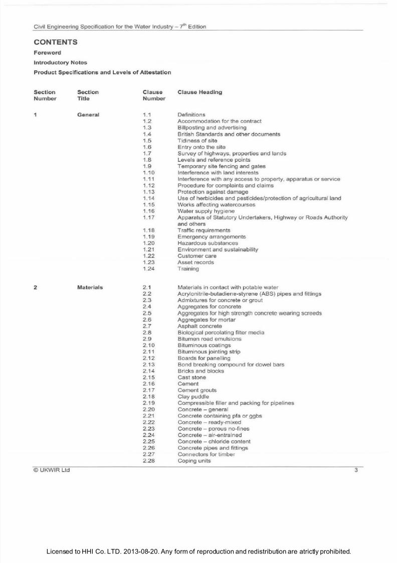
ONTENTS
Foreword
Introduc
tory Notes
Product Specifications and Leve ls of Attestation
Section
Number
1
2
© UKWIR Ltd
Section
Title
General
Materials
Clause
Number
1 1
1 2
1 3
1 4
1.5
1 6
1 7
1 8
1 9
1
10
Clause Head ing
Definitions
Accommodation for the contract
Billposting and advertising
British Standards and other documents
Tidiness of site
Entry onto
th
e site
Survey of highways, properties and lands
Levels and reference points
Temporary site fencing and gates
Interference with land interests
1 11 Interference with any access to property, apparatus
or
service
1 12
Procedure for complaints and claims
1 13
Protection against damage
1 14
Use
of
herbicides and pesticides/protection
of
agricultural land
1 15 Works affecting watercourses
1 16
Water supply hygiene
1 17
Apparatus
of
Statutory Undertakers Highway or Roads Authority
and others
1 18
Traffic requirements
1 19
Emergency arrangements
1 20
Hazardous substances
1 21 Environment and sustainability
1 22
Customer care
1 23 Asset records
1 24 Training
2 1
2 2
2 3
2 4
2.5
2 6
2 7
2 8
2 9
2 10
2 11
2 12
2 13
2 14
2 15
2 16
2 17
2 18
2 19
2 20
2 21
2 22
2 23
2 24
2 25
2 26
2 27
2 28
Materials in contact with potable water
Acrylonitrile-butadiene-styrene ABS) pipes and fittings
Admixtures for concrete
or
grout
Aggregates for concrete
Aggregates for high
strength
concrete
wearing
screeds
Aggregates for mortar
Asphalt concrete
Biological percolating filter media
Bitumen road emulsions
Bituminous coatings
Bituminous jointing strip
Boards for panelling
Bond breaking compound for dowel bars
Bricks and blocks
Cast stone
Cement
Cement grouts
Clay puddle
Compressible filler and packing for p ipelines
Concrete - general
Concrete containing pfa
or
ggbs
Concrete - ready-mixed
Concrete - porous no-fines
Concrete - air-entrained
Concrete ch loride content
Concrete pipes and fittings
Connectors for timber
Cop1ng units
3
7/21/2019 The Civil Engineering Specification for the Water Industry 7th
http://slidepdf.com/reader/full/the-civil-engineering-specification-for-the-water-industry-7th 10/176Licensed to HHI Co. LTD. 2013-08-20. Any form of reproduction and redistribution are atrictly prohibited.
Civil Engineering Specification for the Water Industry -
t
Edition
Section
Number
4
Section
Tit
le
lause
Number
2 29
2 30
2 31
2 32
2 33
2 34
2 35
2 36
2 37
2 38
2 39
2 40
2 41
2 42
2 43
2 44
2 45
2 46
2 47
2 48
2 49
2 50
2 51
2 52
2 53
2 54
2 55
2 56
2 57
2 58
2 59
2 60
2 61
2 62
2 63
2 64
2 65
2 66
2 67
2 68
2 69
2 70
2 71
2 72
2 73
2 74
2 75
2 76
2 77
2 78
2 79
2 80
2 81
2 82
2 83
2 84
2 85
2 86
2 87
2 88
2 89
2 90
2 91
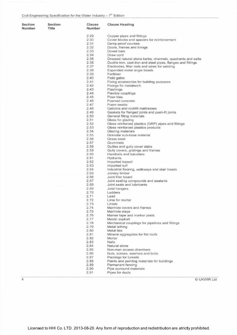
Clause Heading
Copper pipes and fittings
Cover blocks and spacers for reinforcement
Damp-proof courses
Doors, frames and linings
Dowel bars
Draw cord
Dressed natural stone kerbs, channels, quadrants and setts
Ductile iron, cast iron and steel pipes, flanges and fittings
Electrodes, filler rods and wires for welding
Expanded metal angle beads
Fertiliser
Field gates
Fixing accessories for building purposes
Fixings for metalwork
Flashings
Flexible couplings
Floor tiles
Foamed concrete
Foam swabs
Gabions and rockfill mattresses
Gaskets for flanged joints and push-fit joints
General filling materials
Glass for glazing
Glass reinforced plastics GRP) pipes and fittings
Glass reinforced plastics products
Glazing materials
Granular sub-base material
Grass seed
Grummets
Gullies and gully cover slabs
Gully covers, gratings and frames
Handrails and balusters
Hydrants
Imported topsoil
Imported turf
Industrial flooring, wa lkways and stair treads
Joinery timber
Joint filler board
Joint sealing compounds and sealants
Joint seals and lubricants
Joist hangers
Ladders
Lead
Lime for mortar
Lintels
Manhole covers and frames
Manhole steps
Marker tape and marker posts
Mastic asphalt
Mechanical couplings for pipelines and fittings
Metal lathing
Metal ties
Mineral aggregates for flat roofs
Mortar
Nails
Natural stone
Non-man access chambers
Nuts, screws, washers and bolts
Packlngs for tunnels
Paints and painting materials for buildings
Permanent fencing
Pipe surround materials
Pipes for ducts
© UKWIR Ltd
7/21/2019 The Civil Engineering Specification for the Water Industry 7th
http://slidepdf.com/reader/full/the-civil-engineering-specification-for-the-water-industry-7th 11/176Licensed to HHI Co. LTD. 2013-08-20. Any form of reproduction and redistribution are atrictly prohibited.
Civil Engineering Specification for the Water Industry - yth Edition
Section
Number
3
© UKWIR Ltd
Section
Title
Excavation
backfilling
and
restoration
lause
Number
2
92
2
93
2
94
2 95
2 96
2 97
2 98
2 99
2
100
2 101
2 102
2 103
2 104
2 105
2 106
2 107
2
108
2 109
2 110
2 111
2 112
2 113
2 114
2 1 15
2 1 16
2 117
2 118
2 119
2 120
2 121
2 122
2 123
2 124
2 125
2 126
2 127
2 128
2 129
2 130
2 131
2
132
2 133
2 134
2 135
2 136
2 137
2 138
2 139
2 140
2 141
2 142
3 1
3 2
3 3
3.4
3.5
3 6
3 7
3 8
3 9
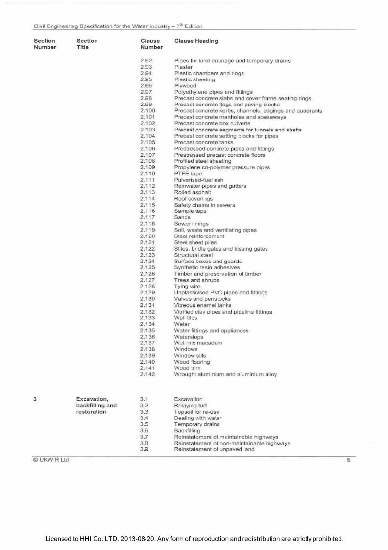
Clause Heading
Pipes for land drainage and temporary drains
Plaster
Plastic chambers and rings
Plastic sheeting
Plywood
Polyethylene pipes and fittings
Precast concrete slabs and over frame seating rings
Precast concrete flags and paving blocks
Precast concrete kerbs channels edgings and quadrants
Precast concrete manholes and soakaways
Precast concrete box culverts
r
ecast concrete segments for tunnels and shafts
Precast concrete setting blocks for pipes
Precast concrete tanks
Prestressed concrete pipes and fittings
Prestressed precast concrete floors
Profiled steel sheeting
Propylene co-polymer pressure pipes
PTFE tape
u
lverised-fuel ash
Ra
inwater pipes and gutters
Roll
ed
asphalt
Roof coverings
Safety chains in sewers
Sample taps
Sands
Sewer linings
Soil waste and ventilating pipes
Steel reinforcement
Steel sheet piles
Stiles bridle gates and kissing gates
Structur
al
steel
Surface boxes and guards
Synthetic resin adhesives
Timber and preservation of timber
Trees and shrubs
Tying wire
Unplasticised PVC pipes and fittings
Valves and penstocks
Vitreous enamel tanks
Vitrified clay pipes and pipeline fittings
Wa ll tiles
Water
Water fittings and appliances
Waterstops
Wet-mix macadam
Windows
Windowsills
Wood flooring
Wood trim
Wrought aluminium and aluminium all
oy
Excavation
Relaying turf
Topsoil for re-use
Dealing with water
Temporary drains
Backfilling
Reinstatement of maintainable highways
Re instatement
of
non-maintainable highways
Reinstatement
of
unpaved land
5
7/21/2019 The Civil Engineering Specification for the Water Industry 7th
http://slidepdf.com/reader/full/the-civil-engineering-specification-for-the-water-industry-7th 12/176Licensed to HHI Co. LTD. 2013-08-20. Any form of reproduction and redistribution are atrictly prohibited.
Civil Engineering Specification for the Water
Industry
hEdition
Section
Number
4
5
6
Section
Title
Concreting and
formwork
Construction
of
pipelines and
anc il lary works
Clause
Number
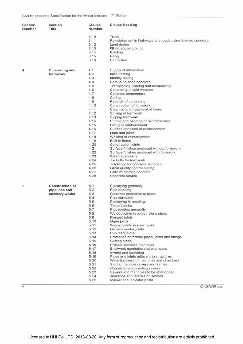
Clause Heading
3.10 Trees
3.11 Reinstatement in highways and roads using foamed concrete
3.12 Land drains
3.13 Filling above ground
3.14 Blasting
3.15 Piling
3.16 Demolition
4.1
4.2
4.3
4 4
4.5
4.6
4 7
4 8
4 9
4.10
4.11
4.12
4.13
4 14
4 15
4 16
4 17
4 18
4 19
4.20
4.21
4.22
4.23
4.24
4 25
4 26
4 27
4.28
5 1
5 2
5.3
5 4
5 5
5.6
5 7
5.8
5 9
5.10
5.11
5 12
5 13
5.14
5.15
5 16
5.17
5 18
5 19
5 20
5 21
5 22
5 23
5 24
5.25
Supply of information
Initi
l
testing
Identity testing
Porous no-fines concrete
Transporting placing and compacting
Concreting
in
cold weather
Concrete temperature
Curing
Recor
ds
of concreting
Construction
of
formwork
Cleaning and treatment of forms
Striking of formwork
Sloping formwork
Cutting and bending
of
reinforcement
Fixing of reinforcement
Surface condition of
re
inforcement
Laps and joints
Welding of reinforcement
Built-in items
Construction joints
Surface finishes produced without formwork
Surface finishes produced with formwork
Wearing screeds
Tie bolts for formwork
Tolerance for concrete surfaces
Grout quality control testing
Fibre reinforced concrete
Concrete repairs
Pipelaying generally
Pipe bedding
Concrete protection to pipes
Pipe
su
rround
Pipelaying in headings
Thrust blocks
Pipe jo inting generally
Welded joints in polyethylene pipes
Flanged
jo
ints
Ogee joints
Welded jo ints in steel pipes
Cement mortar joints
Run lead joints
Protection
of
ferrous pipes joints and fittings
Cutting pipes
Precast concrete manholes
Brickwork manholes and chambers
Inverts and benching
Pipes and joints
d
jacent to structures
Watertightness
of
manholes and chambers
Setting manhole covers and frames
Connections to existing sewers
Sewers and manholes to
be
abandoned
Junctions and laterals on sewers
Marker and indicator posts
© UKWIR Ltd
7/21/2019 The Civil Engineering Specification for the Water Industry 7th
http://slidepdf.com/reader/full/the-civil-engineering-specification-for-the-water-industry-7th 13/176Licensed to HHI Co. LTD. 2013-08-20. Any form of reproduction and redistribution are atrictly prohibited.
Civil Engineering Specification for the Water
Industry
J h Edition
Section Section Clause
Clause Head
ing
Number
Title Number
5 26
Tolerances for pipelines
5 27
Cable ducts
5 28
Installation
of
valves
5 29 Washouts
5 30
Alternative pipe installation techniques
5 31
Connections to existing water supply pressure pipelines
5 32 Temporary water supply mains
5 33 Water mains to be abandoned
6
Building works 6 1 Brickwork and blockwork generally
6 2
Brickwork and blockwork jointing and pointing
6 3 Cavity walls
6 4
Damp-proof courses
6 5 Corbelling
6 6 Bonding to concrete
6 7 Underpinning
6 8
Centering and lagging
6 9
Bricklaying and blocklaying in cold weather
6 10 Preparation for plastering
6 11
Fixing
of
plasterboard
6 12
Plastering
6 13 Plastering in cold weather
6 14 Concrete floor finishes
6 15
Floor tiling
6 16 Terrazzo floor finishes
6
17 External rendering
6 18
Wall tiling
6 19
Carpentry and joinery
6 20 Structural steelwork
6 21
Roofs
6 22
Timber floors
6 23 Door frames
6 24
Windows
6 25
Glazing
6 26 Painting
6 27 Slating and tiling
6 28
Lightweight concrete roof screeds
6 29 Asphalt roofing
6 30 Bitumen felt roofing
6 31 Plumbing
6 32 Openings in walls floors and ceilings
6 33 Tolerances for building works
6 34
Electrical installations
6 35 Profiled steel cladding
6 36
Precast concrete floors
6 37
Composite floors
7 Testing
and 7 1 Cleansing and swabbing
of
pipelines
disinfection 7 2 Precautions prior to testing pipelines
7 3
Testing method programme and notification
7 4
Testing non-pressure pipelines
7 5
Water test for non-pressure pipelines
7 6 Air test for non-pressure pipelines
7 7
CCTV inspection
of
pipelines
7 8 Infiltration
7 9 Testing of ductile iron PVC GRP and steel pressure pipelines
7 10
Testing
of
polyethylene pressure pipelines
7 11
Disinfection
of
water mains
7 12
Cleansing
of
structures
7 13 Testing of concrete roofs
7 14
Testing
of
concrete structures designed to retain an aqueous liquid
7 15 Disinfection
of
structures for potable water
©UKWIR Ltd
7
7/21/2019 The Civil Engineering Specification for the Water Industry 7th
http://slidepdf.com/reader/full/the-civil-engineering-specification-for-the-water-industry-7th 14/176Licensed to HHI Co. LTD. 2013-08-20. Any form of reproduction and redistribution are atrictly prohibited.
Civil Engineering Specification for the Water Industry - 7t Edition
Section Section lause Clause Heading
Number Title Number
7.16 Water for testing swabbing and disinfection
7.17 Disposal of water from cleansing testing or disinfection
7.18
Testing of non-concrete structures for retaining aqueous liquids
8 Roadworks 8 1 Roa d formations
8.2 Sub-base construction
8.3
Wet-mix macadam
co
nstruction
8.4 Lean concrete construction
8.5 Laying coated macadam
8.6 Laying hot rolled asphalt
8.7 Waterproof underlay for concrete carriageways
8.8 Reinforcement of concrete carriageways
8.9 Laying concrete ca
rri
ageways
8.10 Laying kerbs an d channels
8 1 1 Founda
ti
ons for footways
8.12 Laying concrete paving flags
8.13 Laying paving blocks
8.14 Tolerances for finished carriageway surfaces
8.15 Fixing
of
gullies
8.16 Lining and signage
8.17 Concrete footways
9
Se
wer
renovation 9.1 Isolation
of
flows
9.2 Preparatory survey
9.3
Preparation
of
sewers
9.4 Jointing generally
9.5 Connections
9.6 Chambers
9.7 Re lease
of
curing water
9.8 Annulus grouting generally
9.9 Inspection after grouting
9.10 Lining through flow control devices
9.11 Inspection after renovation
9.12 Lining template
9.13 Lining design
9.14
To lerances for preformed linings
9.15 Cutting and protection
of
linings
9.16 Man-entry preformed GRP and GRC units
9 17
Cured-in-place lining systems
9.18 Rendering and local repairs
9.19 Patch repairs
9.20 Styrene fumes
9.21 Spray lining
10 Water mains 10.1 Preparatory survey
rehab ilitation
10.2 Preparation of water mains
10.3 In-situ linings
10.4 Sliplining and replacement moling
10.5 Connections
10.6 Lining through valves
10.7 Inspection after in-situ re-lining
10.8
Bringing rehabilitated water mains into service
Tunnelling and shaft 11.1 Headings tunnels and shafts
sinking works 11.2
Shafts
11.3 Openings in shafts and tunnels
11.4 Segmental shaft and tunnel linings
11.5 Unbolted concrete tunnel segments
11.6 Bolted concrete segmental linings
11.7 Grouting
of
segments
11.8
Caulking
8 © UKWIR l td
7/21/2019 The Civil Engineering Specification for the Water Industry 7th
http://slidepdf.com/reader/full/the-civil-engineering-specification-for-the-water-industry-7th 15/176Licensed to HHI Co. LTD. 2013-08-20. Any form of reproduction and redistribution are atrictly prohibited.
Civ
il
Engineering Specification for the Water Industry yl Edition
Section
Number
Appendices
© UKWIR Ltd
Section
Title
Clause
Number
Clause Heading
11.9 Pointing of joints
11.10 Secondary linings to segments
11.11 Watertightness of shafts and tunnels
11.12 Control of groundwater
11.13 Pipe jacking
11.14 Microtunnelling
11.15 Ventilation of tunnels and shafts
11.16 Work in compressed air
11.17 Recording of information
.18 Tolerances for shafts tunnels and pipe jacks
Incorporation of Specifica tion Into Contracts
List of Standards
I
II
Ill
IV
v
VI
List of Water Industry Specifications/Information and Guidance Notes
List of CIR IA Publications
List of Statutory References
List of Other Publications

7/21/2019 The Civil Engineering Specification for the Water Industry 7th
http://slidepdf.com/reader/full/the-civil-engineering-specification-for-the-water-industry-7th 16/176Licensed to HHI Co. LTD. 2013-08-20. Any form of reproduction and redistribution are atrictly prohibited.
ivil Engineering Specification for the Water ndustry ? h Edition
1
© UKWIR Ltd
7/21/2019 The Civil Engineering Specification for the Water Industry 7th
http://slidepdf.com/reader/full/the-civil-engineering-specification-for-the-water-industry-7th 17/176Licensed to HHI Co. LTD. 2013-08-20. Any form of reproduction and redistribution are atrictly prohibited.
Civil Engineering Specification for the Water
Industry
Edition
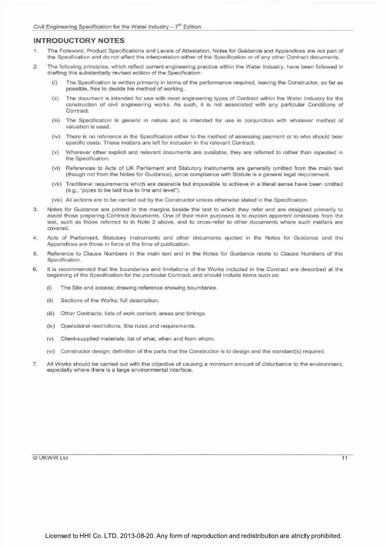
INTRODU TORY NOTES
1. The Foreword, Product Specifications and Levels of Attestation, Notes for Guidance and Appendices are not part of
the Specification and do
not
affect the interpretation either
of
the Specification or of any other Contract documents.
2.
The
following principles, which reflect current engineering practice within the Water Industry, have been followed in
drafting this substantially revised edition
of
the Specification:
(i) The Specification is written primarily in
te
rms
of
the performance required, leaving the Constructor,
so
far as
possible, free to decide his method
of
working.
(ii) The document is intended for use with most engineering types of Contract within the Water Industry for the
construction
of
civil engineering works.
As
such, it is not associated with any particular Conditions
of
Contract.
(iii) The Specification is generic in nature and is intended for use in conjunction with whatever method
of
valuation is used.
(iv) There is no reference in the Specification ei
th
er
to
the method of assessing payment or to who should bear
specific costs. These matters are left for inclusion in the re levant Contract.
(v) Wherever other explicit and relevant documents are available, they are referred to rather than repeated in
the Specification.
(vi) References to Acts
of
UK
Parliament and Statutory Instruments are generally omitted from the main text
(though not from the Notes for Guidance), since compliance with Statute is a general legal requirement.
(vii) Traditional requirements which are desirable but impossible to achieve in a literal sense have been omitted
(e.g., pipes to be laid true to l
ine
and level ).
(viii) All actions are to be carried
out
by the Constructor unless otherwise stated in the Specification.
3. Notes for Guidance are printed in the margins beside the text to which they refer and are designed primarily to
assist those preparing Contract documents. One of their main purposes is to explain apparent omissions from the
text, such as those referred to in Note 2 above, and to cross-refer to other documents where such matters are
covered.
4. Acts
of Parliament, Statutory Instruments and other documents quoted in the Notes for Guidance and the
Appendices are those in force at the time of publication.
5. Reference to Clause Numbers in the main text and in the Notes for Guidance relate to Clause Numbers
of
th
is
Specification.
6. It is recommended that the boundaries and limitations of the Works inc luded in the Contract are described at the
beginning
of
the Specification for the particular Contract, and should include items such as:
(i) The Site and access; drawing reference showing boundaries.
(ii) Sections of the Works; full description.
(iii) Other Contracts; lists
of
work content, areas and timings.
(iv) Operational restrictions; Site ru les and requirement
s
(v) Client-supplied materials; list
of
what, when and from whom.
(vi) Constructor design; definition of the parts that the Constructor is to design and the standard(s) required .
7. A
ll
Works should be carried out with the objective of causing a minimum amount of disturbance to the environment,
especially where there is a large environmental interface.
UKWIR Ltd
11
7/21/2019 The Civil Engineering Specification for the Water Industry 7th
http://slidepdf.com/reader/full/the-civil-engineering-specification-for-the-water-industry-7th 18/176Licensed to HHI Co. LTD. 2013-08-20. Any form of reproduction and redistribution are atrictly prohibited.
Civil Engineering Specification for the Water ndustry
t
Edition
2
©
UKWIR Ltd
7/21/2019 The Civil Engineering Specification for the Water Industry 7th
http://slidepdf.com/reader/full/the-civil-engineering-specification-for-the-water-industry-7th 19/176Licensed to HHI Co. LTD. 2013-08-20. Any form of reproduction and redistribution are atrictly prohibited.
Civil Engineering
Sp
ecification for the Water Industry - yth
Ed
iti
on
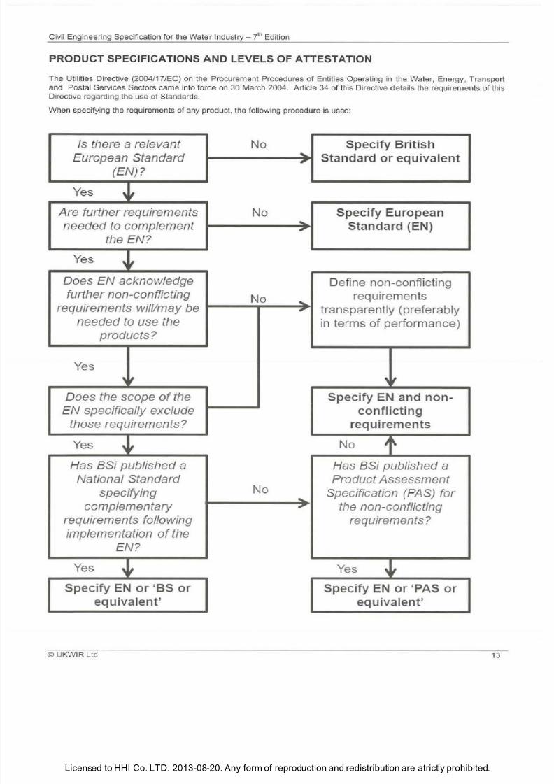
PRODUCT SPECIFICATIONS AND LEVELS OF ATTESTATION
The Utilities Directive (2004/17/EC) on the Procurement Procedures
o
En
ti
ties Opera
ti
ng in the Water Energy, Transport
a
nd
Postal Services Sectors came into force on 30 March 2004. Article 34
o
this Directive d etails the requirements of this
Directive regardi
ng
the use
o
Standards.
Wh
en
specifying the requirements o any product the following pro
ce
du
re
is us
ed:
/s
there
a
relevant
No
Specify British
European Standard Standard or eq uivalent
EN)?
Yes
Are further requirements
No
Specify European
needed t complement
Standard (EN)
.
the EN?
Yes
Does EN acknowledge
Define non-conflicting
further non-conflicting
No
requirements
requirements will/may be
,
transparently (preferably
needed t use the
in
terms o performance)
products?
Yes
Does the scope
o
the
Specify
N
and non-
EN specifically exclude
conflicting
those requirements?
requirements
Yes
+
No
1
Has
BSi published a
Has
BSi published a
National Standard Product Assessment
specifying
No
Specification PAS) for
complementary
,.
the non-conflicting
requirements following
requirements?
implementation o the
EN?
Yes
+
Yes
_i
Specify
N
or BS
r
Specify
N
or PAS or
equivalent equivalent
© UKWIR ltd
13
7/21/2019 The Civil Engineering Specification for the Water Industry 7th
http://slidepdf.com/reader/full/the-civil-engineering-specification-for-the-water-industry-7th 20/176Licensed to HHI Co. LTD. 2013-08-20. Any form of reproduction and redistribution are atrictly prohibited.
Civil Engineering Specification for the Water Industry - J h Edi
ti
on
14
A relevant
EN
is any
EN
covering
the
subject in question which is
in
force in the EU.
In
the UK, ENs are publ ished as
BS
ENs. A Water Industry Specification may
be
used where there is no relevant
EN
,
BS
or equivalent ava ilable.
A European Standard, British Standard or equivalent will not normal ly be available in the case of newly-developed
products but th is is not to be seen as inhibiting the use of such products. Water Industry Specifications, issued by the
Water UK Standards Board, deal with products such as these and are ca ll
ed
up in the Specification. However, in the
case
of
any innovatory product for which no European Standard, British Standard or Water I
nd
ustry Specification (or
the equivalent
of
ei th er) exists, care shou ld be taken to ensure that the product is fit for
pu
rpose. This might
be
achieved by using products which have been assessed by
an
independent body. The British Board of Agrement
(BBA) is authorised to issue European Technical Approvals under the provisions
of
the Construction Products
Directive 89/1 06/EEC).
Under the provisions
of
the Construction Products Directive (89/106/EEC), the European Commission decides the
appropriate level of attestation when a harmonised Eu ropean Specification is published under a mandate given in
connection with that Directive. The Specification, therefore, now provides for Levels
of
Attestation less stringent than
full Third Party Certification, where so decided by the Commission.
Where the product is also covered
y
a Mandate under the provisions
of
the Construction Products Directi
ve
89/1 06/EEC), the relevant system
of
conformity attestation chosen by the Commission
of
the European Community
(CEC), and leading to the use
of
the CE mark for a product, applies to those elements of the product specification
which relate to the Mandate. Third Party Certifica
ti
on is recommended as a cost-effective means
of
ensuring
compliance with Standards. However, Water Industry pol icy is for ind ividual purchasers to determine where Third
Party Certifica
tion
is required.
Additional quality assurance requirements, including Third Party Certification, may be sought
y
the purchaser as a
cost-effective means
of
ensuring compliance with Standards. BSi Kitemarking is an example
of
Th
ir
d Party
Certification.
Currently, where European Standa rds refer to req uirements for the effect of materials on potable water quality,
National Regulations apply. Before accepting any material which will come in to contact with potable water or water to
be used for potable supply, the Client will have regard to the provisions of:
a) For England:
Water Supply (Water
Quality) Regulations 2010 (SI 2010 No. 994 (W.99)).
(b) For Scotland:
Water Supply (Water Quality) (Scotland) Regulations 2001 (SI 2001/207).
(c) For Northern Ireland:
Water Supply (Water Quality) Regulations (Northern Ireland) 2002 (SR 2002/331
).
Reference should be made to the cu rrent list of approved substances prepared by the Dr inking Water Inspectorate.
Reference should also be made to the Water Fittings and Materials Directory , published by the Water Regulations
Advisory Scheme Ltd on its website (www.wras.co.uk/dorectory).
Requirements for the testing
of
materials for use in contact with potable water are dealt with in:
i)
DD
256 for metal
li
c materials.
ii) BS 6920-1 for non-metallic materials.
Due consideration should be given to selecting materials which promote sustainabi li ty and minimise environmental
impact.
UKWIR Ltd
7/21/2019 The Civil Engineering Specification for the Water Industry 7th
http://slidepdf.com/reader/full/the-civil-engineering-specification-for-the-water-industry-7th 21/176Licensed to HHI Co. LTD. 2013-08-20. Any form of reproduction and redistribution are atrictly prohibited.
Civil Engineering Specification for the Water Industry -
7
l Edition
The Notes for Guidance are not part of
the Specification
i) The Contract could be a construction
agreement e.g., NEC or /ChernE, or an
adoption agreement, e.g., Self Laying of
Water Mains and Services.
i) Consent
of
the Local Planning
Authority may be required for Site
accommodation.
ii) BS 6767-1 deals with transportable
accommodation units.
iii) Reinstatement is covered in Clause
9
iv)
Details
of
accommodation and
disposal
of
all domestic types of waste
should be stated in the Contract.
{v) Any special insurance requirements
should be a Special Condition of
Contract.
vi)
The
siting nd availability of all
accomodation should be stated in the
Contract.
i)
Notice boards
or
scheme signboards
required by the Client should be detailed
in the Contract.
ii) Notice boards nd signboards should
be erected and maintained by the
© UKWIR Ltd
SECTION
GENERAL
1.1
DEFINITIONS
1. This Specification is written on the assumption that the Party entering into
a Contract that includes this Specification will be bound by the Specification
terms and be responsible for following its provisions.
2. Party means a company, contractor, alliance, joint venture, consortium,
etc.
3. Client means the person or persons, firm, company or other body for
whom
the
Works are to be constructed and includes the Client's personal
representatives, successors and permitted assignees.
4. Environmental Regulator means in England and Wales, the
Environment Agency (EA), in Scotland, the Scottish Environmental
Protection Agency (SEPA) and
in
Northern Ireland, the Northern Ireland
Environment Agency (NIEA).
5. River Authority means
in
Eng land and Wales, the Environment Agency
{EA),
in
Scotland, the Scottish Environmental Protection Agency (SEPA)
and
in
Northern Ireland, the Department for Agriculture and Rural
Development.
6. The Highway Reinstatement Specification means
in
England,
'Specification for the Reinstatement of Openings in Highways', Department
for Transport and published by HAUC. In Scotland it means the
'Specification for the Reinstatement of Openings in Roads' the Scottish
Government.
In
Wales it means 'The Specification for the Reinstatement of
Openings
in
Highways 2nd Edition), Welsh Assembly Government.
1.2 ACCOMMODATION FOR THE CONTRACT
1. Until the completion of the Works, accommodation and parking faciliti es,
as described in the Contract, shall be equipped and maintained.
Accommodation shall be erected, furnished , equipped, fully serviced and
ready for use within 7 days of the work commencing on Site.
2. Where movable offices are required by
the
Contract, these shall be
relocated as directed under the terms
o
the Contract.
3. Where the Contract requires telephone facilities
to be
provided, such
faci lities shall have separate connections with privacy of conversation.
4.
All Site accommodation, services and parking sha
ll
be removed upon
completion of the Works or at such other date as directed under the terms
o
the Contract.
1.3 BILLPOSTING AND ADVERTISING
1. Billposting or advertising of any kind shall not
be
undertaken,
un
less
otherwise stated
in the
Contract.
5
7/21/2019 The Civil Engineering Specification for the Water Industry 7th
http://slidepdf.com/reader/full/the-civil-engineering-specification-for-the-water-industry-7th 22/176Licensed to HHI Co. LTD. 2013-08-20. Any form of reproduction and redistribution are atrictly prohibited.
Civil Engineering Specification for the Water Industry n Edition
Contractor at a location and in the form,
layout and number
as
specified in
accordance with the Contract.
iii) Consent
of
the Local Planning
Authority
may
be required for notice
boards
or
signboards.
i} ny particular requirements should be
described in the Contract after taking
due account
of
the guidance in the
Product Specifications and Level of
Attestation
at
the front
of
CESWI.
ii)
Where appropriate, use should be
made
of
any technical
and
advisory
services offered by manufacturers.
i) Special storage requirements should
be
described in the Contract.
i) The Contract should prescribe the
extent
of
the Site, including working
areas accesses and
the periods
for
which they will be available. Reference
should
be
made to
any
known hazards.
ii) The Client
may
have to obtain
planning permission where an access
from classified road
or
street is
specified.
iii)
It
should
be
assumed that formal
entry notices have already been served
by the Client, and owners and occupiers
have been alerted to impending entry.
iv) The Contract should describe
any
Code
of
Practice
or
other relevant
documentation in connection with
pipelaying on private land.
v) ny requirements for entry on third
party land, including
any
notice required,
should be specified in the Contract.
i) The composition and extent
of
the
survey should be detailed in the
Contract and
may
include photographs,
video recordings, sketches and
professional reports.
16
1.4
BRITISH STANDARDS AND OTHER DOCUMENTS
1. British Standards and other documents referred to in the Contract shall
be deemed to be those current 28 days prior to the date for return of
Tenders.
2. Any reference in the Contract to a Standard published by the British
Standards Institution or to the Specification of another body shall be
construed equa lly as reference to an equivalent one.
1.5 TIDINESS OF SITE
1. Materials plant and equipment shall be positioned stored and stacked in
an orderly manner.
2. All pipes and fittings shall be stored off the ground
in
a clean
environment
to
prevent any contamination of materials prior
to
their use.
3. All Site waste
and
surplus
sha
ll be removed from Si
te.
4. Pipe
end
caps shall be fitted at either
end
of the pipe until the pipe is
used in the Works to prevent vermin entering.
1.6 ENTRY ONTO THE SITE
1. The Client shall at all reasonable times have access to the Works and to
the Site
and
to all workshops and places where work is being prepared or
from where materials manufactured articles and machinery are obtained for
the Works
and
every facility for and every assistance in obtaining such
access or the right to such access shall be afforded.
2. Records shall be kept of the dates of the entry onto and departure from
all property and lands of each owner and occupier.
3. Records shall be kept of the dates of the erection and removal of all
enclosures.
4. Copies of these records shall be provided as specified
in
the Contract.
Copies of similar records
in
respect of roads footpaths and thoroughfares
shall be kept.
5. No part of the Site shall either be entered or used for any purpose
unconnected with the Works.
1.7 SURVEY
OF HIGHWAYS PROPERTIES AND LAND
1. Prior to entry and where appropriate surveys shall be carried out of the
condition of highways properties lands including trees boundaries crops
and any other features which may be affected by
the
Works.
2.
The survey shall
be
carried out with the responsible Highway Authority
and owners or occupiers.
©UKWIR
l td
7/21/2019 The Civil Engineering Specification for the Water Industry 7th
http://slidepdf.com/reader/full/the-civil-engineering-specification-for-the-water-industry-7th 23/176Licensed to HHI Co. LTD. 2013-08-20. Any form of reproduction and redistribution are atrictly prohibited.
Civil Engineering Specification for the Water Industry - h Edition
(ii) The Contract should describe any
special requirements for land used for
organic farming.
(iii)
The
format
of
the survey record
photographs should be stated in the
Contract.
i) The Contract should prescribe the
datum level for the Works, together with
ny
master benchmarks. Precise
reference of the Works to existing
features
or
to the Ordnance Survey
National Grid should be shown.
(ii) Local differences can arise between
GPS and OS coordinates.
i) The location and type of fencing
including access and gates, should be
detailed in the Contract.
i) All land required for the Works should
be prescribed in the Contract. Additional
land or interests found necessary
to
carry out the Works may need to be
obtained, including
ny
associated
planning consent.
(ii) The Contract should describe any
special precautions necessary to comply
with the Client s obligations.
(iii)
The
availability and location
of
accommodation and storage areas
outside the Site should be stated in the
Contract.
©
UKWIR Ltd
3. A representative selection
of
photographs shall
be
provided in a digital
format CD or DVD) for the purpose of the survey record. Each photograph
shall be uniquely numbered and dated.
4
All photographs/records sha ll be signed by the landowner s a true
record of the condition of the property and land, prior to the commencement
of
the Works.
1 8 LEVELS AND REFERENCE
PO
INTS
1 Details sha
ll be
provided
of
the level and location of the temporary
benchmarks and reference points which are proposed to be used.
1.9 TEMPORARY SITE FENCING AND GATES
1. The Site shall
be
adequately fenced.
2.
Where the type and locations
of
temporary site fencing and gates are
described in the Contract, such fencing and gates shall be erected before
commencing any other work in that portion of the Site.
3. All Site fencing and gates shall be regularly inspected and maintained,
and any defects made good without delay. Access shall be provided in
temporary Site fencing and gates,
as
necessary, for the use
of
the
occupiers
of
adjacent lands.
4.
Temporary Site fencing and gates shall remain in position until either they
are replaced with permanent fencing and gates , or the Works are
sufficiently completed to enable that portion of the Site to
be
brought into
use.
1.10 INTERFERENCE WITH LAND INTERESTS
1. Constructional operations shall be confined within the Site, or such other
areas of land as may
be
negotiated. No trespass or breach of ny rights,
bye-laws or regulations shall take place.
2. Subject to any unavoidable disturbance which may
be
necessitated by
the execution of the Contract any
rights which
may be
enjoyed
on or
near
the Site shall not be interfered with.
3. Before exercising any right negotiated in connection with wayleaves,
easements or accommodation outside the Site, written notification of such
arrangements shall
be
provided prior to entry.
1.11
INTERFERENCE WI
TH
ANY ACCESS TO PROPERTY,
APPARATUS OR SERVICE
1. The access requirements sha ll be identified in the Contract and provided
in advance
of
any property, apparatus
or
service being affected by the
Works. Alternative arrangements shall
be
provided before interfering with
any access to property, apparatus or service. Affected owners and
occupiers shall be notified, in writing,
14
days in advance of ny such
interference and it shall
be
confirmed that alternative arrangements have
been agreed.
2.
Should it become impractical
to
maintain vehicular access
to
any
property, apparatus or service t any time during the construction of the
Works, alternative arrangements shall
be
provided and maintained. Every
17
7/21/2019 The Civil Engineering Specification for the Water Industry 7th
http://slidepdf.com/reader/full/the-civil-engineering-specification-for-the-water-industry-7th 24/176Licensed to HHI Co. LTD. 2013-08-20. Any form of reproduction and redistribution are atrictly prohibited.
Civil Engineering Specification for the Water Industry yth Edition
(i) The Contract should define the
meaning of promptly in accordance
with the service objectives
of the Client.
(ii) The Contract should define any
specific requirements for logging and
dealing
with
complaints and
correspondence,
in
line with Regulatory
requirements.
(i) ny permanent support known to be
required should be described in the
Contract.
(if) NJUG (National Joint Utilities Group)
Publication Volume 4 Guidelines for the
Planning, Installation and Maintenance
of Utility Services in Proximity to Trees'
gives guidance on working near trees.
(i) Where
necessary
the Contract
should detail the requirements to
prevent the spread of agricultural,
animal and poultry diseases including
any restrictions on movement
of
materials.
(ii) The document 'Every Drop Counts -
Keeping Water Clean' by the Crop
Protection Association gives guidelines
on the use
of
pesticides.
(i)
The Client should obtain all
necessary Statutory consents relating to
the permanent Works.
(ii) ny requirement
to
liaise with the
appropriate Land Drainage Authority (or
equivalent) should be described in the
Contract.
(iii) The following Statutory provisions
may
a/so
be relevant:
8
assistance shall be provided to the owner/occupier or tenant affected
by
the
Works to enable them to undertake all aspects
of
their normal activity.
3.
The access and service requirements
of
those with special needs shall
be taken into account.
4.
Work in the highway shall be planned and carried out to minimise the
disruption to access for local residents. Safe pedestrian access to all
properties sha
ll
be maintained
at
all times.
1.12 PROCEDURE FOR COMPLAINTS AND CLAIMS
1. Immediately following any damage or injury arising from the execution of
the Works written notification shall be provided without delay to the Client.
2. Details
of
a
ll
complaints claims or warnings
of
intended claims received
from third parties shall be notified without delay to the Client.
3. Any complaints claims damage or injury by owners
or
occupiers shall be
dealt with promptly.
1.13 PROTECTION AGAINST DAMAGE
1. All necessary precautions shall be taken to avoid causing any
unwarranted damage to highways roads properties lands trees roots
crops boundaries and any other features and the apparatus
of
Statutory
Undertakers the Highway
or
Roads Authority and other parties.
2. Where any portion
of
the Works is close to across or under any existing
apparatus of Statu tory Undertakers the Highway
or
Roads Authority or
other parties temporary support shall be provided and work carried out
around under or adjacent to all apparatus in a manner designed to avoid
damage leakage or danger and to ensure uninterrupted operation.
3. The Client and the Statutory Undertaker Highway or Roads Authority or
owner concerned as appropriate shall be notified should any leakages
or
damage to existing services highways or roads be discovered and every
facility shall be afforded for the repair or replacement
of
the apparatus
affected.
1.14 USE OF HERBICIDES AND PESTICIDES/PROTECTION OF
AGRICULTURAL LAND
1. Details
of
all herbicides and pesticides proposed for use shall be
submitted to the Client for approval.
2. All pesticides shall be selected from the list of approved pesticides
published by DEFRA the Scottish Government and the Welsh Assembly.
1.15 WORKS AFFECTING WATERCOURSES
1. Written notification shall be provided 14 days in advance of any intention
to start any part
of
the Works affecting a watercourse canal lake reservoir
borehole aquifer or catchment area.
2. Watercourses including land and/or road drainage within the Site shall be
maintained in effective working condition
at
all times.
3. A
ll
practicable measures shall be taken to prevent the deposition
of
s
il
t
or
other material in and the pollution
of
or damage to any existing
watercourse canal lake reservoir borehole aquifer or catchment area
arising from operations and acts
of
vandalism.
© UKWIR Ltd
7/21/2019 The Civil Engineering Specification for the Water Industry 7th
http://slidepdf.com/reader/full/the-civil-engineering-specification-for-the-water-industry-7th 25/176Licensed to HHI Co. LTD. 2013-08-20. Any form of reproduction and redistribution are atrictly prohibited.
Civil Engineering Specification for the Water Industry - 7
l
Edition
(a) Impeding Flow in a Watercourse:
Water Resources Act
1991
, Section
107, and Land Drainage Act 1994,
(b) Pollution of a Watercourse or
Underground Strata: Water Resources
ct 1991
, Sections 85, 86
and
90,
Salmon
and
Fresh Water Fisheries
ct
1975, Section 4;
(c) Environmental Protection
ct
1990
and
Environment Act 1995; and
d)
Wildlife and Countryside Act 1981.
(iv) It should be noted that the
requirements
of
the Environment
Agency or SEPA for temporary and/or
permanent Works could have
implications for
the
programme.
v)
Where the Site impinges on an
Aquifer Protection Zone, this should be
stated in the Contract.
(vi) Useful guidance can also be found
in the following documents, CIRIA C650
handbook 'Environmental Good Practice
on Site '
and
CIRIA C649 and C648
'Control
of
Water Pollution from Linear
Construction Projects'.
(vii)
Th
e Environment Agency, SEPA
and
NIEA provide advice
to
industry and
the public on their legal responsibilities
and
good environmental practice
through a series of Pollution Prevention
Guidance Notes (PPGs) (see
www.environment-agency.gov.uk).
i) The use of the term pathogenic
organism test has been avoided since
other tests will be involved.
(ii)
If any particular requirements or local
provisions apply to any requirements in
connection with Clause 1.16.4, then
these should be detailed in the Contract.
(iii) Areas of the Works which are
defined Areas of Restricted Operations
should be detailed in the Contract.
(iv) Particular water supply hygiene
requirements of the Client may be
included
in the Contract.
© UKWIR Ltd
4 Unless otherwise specified, approval shall
be
obtained for all temporary
discharges. crossings or diversions to watercourses from the appropiate
Environment Regulator or River Authority and the work sha
ll
comply
in
all
respects with their requirements.
5 Any construction equipment and vehicles which present a risk of affecting
a watercourse shall be removed from Site.
1.16 WATER SUPPLY HYGIENE
1 All Works relating to the installation of water mains and/or services shall
be
carried out in accordance with the Water Undertaker's Drinking Water
Hygiene Code
and
Water UK's 'Principles of Water Supply Hygiene
and
Technical Guidance Notes (www.water.org.uk).
2 Any person engaged
in
work which is defined by Water UK 's 'Principles
of Water Supply Hygiene: Technical Guidance Notes' as Restricted
Operations shall be registered by the National Water Hygiene Scheme
administered by Energy and Utility Skills (www.eusr.co.uk) and carry a
National Water Hygiene Card.
3
Any person engaged
in
work which is defined by Water UK's 'Principles
of Water Supply Hygiene: Technical Guidance Notes' as a Restricted Area
shall be informed of the need for personal hygiene
and
risk of
contamination, and be issued with the Water Undertaker's Drinking Water
Hygiene Code.
4. As required by the Water Undertaker's Drinking Water Hygiene Code,
written notification shall be provided to the Water Undertaker of personnel
working on Restricted Operations who develop symptoms of certa
in
infectious diseases.
9
7/21/2019 The Civil Engineering Specification for the Water Industry 7th
http://slidepdf.com/reader/full/the-civil-engineering-specification-for-the-water-industry-7th 26/176Licensed to HHI Co. LTD. 2013-08-20. Any form of reproduction and redistribution are atrictly prohibited.
Civil Engineering Specification for the Water
Industry
JhEdition
i) The
Contract may indicate what is
believed to be the details of the
apparatus
of
Statutory Undertakers,
Highway or Roads Authorities and
others close to the Works.
If
these
details are indicated then no warranty
s
given as to the accuracy or
completeness of this information.
(ii) Water UK and British Gas (currently
Transco) have agreed
a
Model
Consultative Procedure for Pipeline
Construction Involving Deep
Excavation , published in
1993.
(iii)
The
information given under Clause
1. 7
.1
would not normally include
connections to and from premises and
street furniture.
iv) Responsibility for carrying out
diversion or removal of apparatus
should be detailed in the Contract.
v) Any requirements of Statutory
Undertakers or public bodies should be
described in the Contract, together with
contact names, locations, telephone and
fax numbers.
vi) For Works likely to affect other
apparatus in a street or road see the
New Roads and Street Works
Act 1991,
or
the Street Works (Northern Ireland)
Order 995
.
i) Chapter 8 of the Traffic Signs
Manual covers many aspects which are
sometimes found
in Specifications, such
as traffic signals and signs, one-way
working and minimum carriageway
widths.
(ii)
The
Contract should state who is
responsible for:
a)
road closures;
b)
road diversions;
(c) New Roads and Street Works Act
notices;
d) temporary traffic control measures -
including noticeboards; and
e)
any local New Roads and Street
Works Act requirements.
(iii) For general requirements relating to
road closures and diversions, see
Paragraph
8.
53
of
Cl1apter 8
of
the
Traffic Signs Manuar.
20
1.17 APPARATUS OF STATUTORY UNDERTAKERS, HIGHWAY OR
ROADS AUTHORITY AND OTHERS
1. Before designing (where relevant) or commencing any excavations,
liaison with all relevant Statutory Undertakers, the Highway or Roads
Authority and other owners of apparatus shall take place to ensure
satisfaction as to the exact position of existing apparatus which may affect,
or
be
affected by, the construction
of
the Works.
2
Written notification shall be provided in advance of any diversion or
removal of apparatus which may be required for convenience or because of
the proposed method
of
working.
3. A drawing of all services and apparatus encountered shall be provided to
the Client. It shall highlight any differences with the information provided by
the Statutory Undertaker
and
Highway or Roads Authority.
4. The
HSE
Gu idance Notes, Statutory Undertakers and private company
requirements shall be fully complied with when working
in
the vicinity of their
apparatus.
1.18 TRAFFIC REQUIREMENTS
1. There
sha
ll be full compliance with the Code of Practice Safety at Street
Works and Road Works issued by the Secretaries of State for Transport,
Scotland and Wales under Sections 65 and 124 of the New Roads and
Street Works Act 1991 as amended by the Traffic Management Act 2004,
and the Department of Environment (Northern Ireland) under Article 25 of
the Street Works (Northern Ireland) Order 1995. Additionally, there shall be
full compliance with the relevant provisions of the Traffic Safety Measures
for Road Works, as contained in Chapter 8 of the Traffic Signs Manual
(http://www.dft.gov.ukl) .
2. Before any work in , or affecting the use
of,
any highway or road
is
commenced, the proposed method of working, including any special traffic
requirements, shall
be
agreed with, and confirmed
in
writing
to,
the Client,
the Highway or Roads and Police Authorities.
3.
All construction concerning Works
in
, or access to, the highway or road
shall be carried out in co-operation with the Highway or Roads and Police
Authorities.
4. Where the diversion or closure of any existing carriageway, footway or
public right of way
is
temporarily necessitated by the Works, then an
alternative shall be provided and maintained which shall be operational
before any interference with the existing way takes place.
5.
Where ramps are required, they shall be provided and maintained
to
a
standard suitable in all respects for the class or classes of traffic or
pedestrians requiring to use them.
©
UKWIR
Ltd
7/21/2019 The Civil Engineering Specification for the Water Industry 7th
http://slidepdf.com/reader/full/the-civil-engineering-specification-for-the-water-industry-7th 27/176Licensed to HHI Co. LTD. 2013-08-20. Any form of reproduction and redistribution are atrictly prohibited.
Civil Engineering Specification for the Water Industry
7th
Edition
(iv) Arrangements made with the
Highway or Roads and Police
Authorities may include provisions for
essential users, such as buses and
refuse collection.
(v) Consultation and coordination with
the Highway Authority may require
specific timescales for planning and
coordination. Details should be provided
in the Contract.
(vi) Direction 34(1)(b)
of
the Traffic
Signs Regulations and General
Directions 1994 No 1519 and
the
Specification for Portable
Traffic
Signal
Control Equipment for use at Roadworks
TR 2502 should be referred to.
(i)
The
Contract should indicate
the
responsibility for Site security.
(i)
The
following Statutory and other
provisions are also relevant:
• Storage and Use
of
Explosives:
Construction (General Provisions)
Regulations 1961, Part VI, Explosives
Acts 1875 and 1923 and Orders in
Council Nos. 6, 6A , and 6C, made under
the 1875
ct
and Control
of
Explosives
Regulations 1991;
• Storage
of
Petroleum: Petroleum Spirit
(Motor Vehicles etc.) Regulations 1929,
Petroleum (Consolidation) Act 1928 and
Petroleum (Consolidation Act (Northern
Ireland) 1929;
The Dangerous Substances and
Explosive Atmospheres Regulations
2002 and
The
Dangerous Substances
and
Explosive Atmospheres Regulations
(Northern Ireland) 2003;
• The Planning (Hazardous Substances)
Regulations 1992 (as amended for
England, Scotland and Northern
Ireland);
•
The
Planning (Control of Major
Accident Hazards} Regulations 1999,
the Planning (Control
of
Major-Accident
Hazards} Regulations (Northern Ireland)
UKWIR
l td
6 All reasonable steps shall be taken to prevent vehicles entering
and
leaving the Site depositing mud or other debris on the surface of adjacent
roads or footways, and any materials so deposited shall be removed
expeditiously.
7. An up-to-date list of supervisors and operatives who have achieved
accreditation in the relevant activities specified
in
the New Roads and Street
Works Act
1991
as amended by the Traffic Management Act 2004 or the
Street Works Northern Ireland) Order 1995 shall be maintained on Site.
8 Emergency vehicle access to all properties shall be maintained at all
times.
9 The Works shall be planned and executed to ensure that all relevant
notices are submitted within the required times, and such that relevant
coordination activities with the Highway Authority can be carried out.
10 Where restricted worki
ng
hours apply, al l excavations
in the
section of
highway to wh ich the restriction app
li
es shall be backfilled and reinstated to
an interim standard or covered with a road plate where the Highway
Authority permits.
11 Applications shall be submitted to the appropriate Highway Authority for
approval to use portable traffic signal equipment, as necessary, on each
occasion.
1.19 EMERGENCY ARRANGEMENTS
1 Arrangements shall be maintained whereby labour, materials and
equipment
can
quickly be called out, outside normal working hours, to carry
out any work needed for an emergency associated wi
th
the Works.
An
up
to-date list of addresses and telephone numbers of the staff who are
currently responsible for organising emergency work shall be maintained.
2 Employees shall be made aware of any relevant arrangements, including
those of the Client, which are
in
existence for dealing with emergencies.
1.20 HAZARDOUS SUBSTANCES
1
Hazardous substances shall not be brought onto the Site, used for any
purposes or incorporated into the Works without
the
prior written consent of
the Site owner, unless specified
in
the Contract. All necessary licences shall
be obtained .
2 The location of each explosives magazine and store of any other
hazardous substance on the Site shall be approved
in
writing.
3 The storage of blasting explosives shall be in accordance with the
conditions if any) of the Statutory licence obtained and the relevant
provisions of BS 5607.
21
7/21/2019 The Civil Engineering Specification for the Water Industry 7th
http://slidepdf.com/reader/full/the-civil-engineering-specification-for-the-water-industry-7th 28/176Licensed to HHI Co. LTD. 2013-08-20. Any form of reproduction and redistribution are atrictly prohibited.
Civil Engineering Specification for the Water
Industry ~ t ~
Edition
2000, the Planning (Control o Major-
Accident Hazards) Regulations
(Scotland) 2009; and
•
The
Control
o
Pollution (Oil Storage)
(England) Regulations 2001 and the
Control o Pollution (Oil Storage)
(Northern Ireland) Regulations 2010.
i) Copies
o
the Client s policy should
be included in the Contract.
(ii) The following publications are
available from CIRIA: Environmental
Handbooks for Building and Civil
Engineering Projects and
Environmental Impact o Materials .
(iii)
The
Contract should state any
requirements in connection with
environmental
or
ecological surveys
required to be undertaken by the
Contractor (or any other patty) prior to
the starl
o
construction.
iv) Guidance is available in the
Pollution Prevention Guidelines
(http://publications.environment-
agency.gov.ukl).
v) Details
o
any known controlled
wastes that require removal from Site
should be included in the Contract.
vi) Guidance on recycling opportunities
can be obtained from WRAP
www.
wrap.org.uk).
(vii) Guidance on materials management
plans can be obtained from the
CL.·AIRE
Code o Practice (www.claire.co.uk).
(viii) Work in and around hedgerows
should comply with the requirements o
the Hedgerows Regulations 1997.
ix) Specific requirements
o
planning
perm1ss1on
or
environmental risk
assessments should be specified
in
the
Contract.
x) All relevant guidance should be
followed that is issued by the
environmental regulator in connection
with pollution prevention.
xi) Reference should be made to the
Site Waste Management Plan
Regulations 2008.
i) Copies o the Client s policy should
be included in the Contract.
22
1 21 ENVIRONMENT AND SUSTAINABILITY
1
Design and construction
of
the Works shall
be
carried out in accordance
with any environmental mitigation measures specified in the Contract.
2 All
Site operations shall be managed to minimise waste
of
construction
materials and maximise the recycling
of
waste.
3. The Contractor shall make his Site staff and contractors fully aware of
any specific environmental practices relevant to the Site including the
process for reporting environmental incidents specified
in the Contract.
1.22 CUSTOMER CARE
1 All construction operations shall be carried out with due regard for the
customer care policy specified in the Contract.
©UKWIR
Ltd
7/21/2019 The Civil Engineering Specification for the Water Industry 7th
http://slidepdf.com/reader/full/the-civil-engineering-specification-for-the-water-industry-7th 29/176Licensed to HHI Co. LTD. 2013-08-20. Any form of reproduction and redistribution are atrictly prohibited.
Civil Engineering Specification for the Water
Industry
JhEdition
i) Details o the Client s requirements
should be included in the Contract.
i) Details o the Client s requirements
should be included in the Contract.
UKWIR Ltd
1.23 ASSET RECORDS
1. As-built records of all Works constructed, and existing services
encountered during the construction of the Works, shall be submitted in
accordance wi
th the
Contract
1.24 TR INING
1.
The Client s staff, or appointed representatives, shall be trained in the
operational and maintenance requirements for any new installation. This
training shall be provided just prior to take over and at times to suit the
Client s staff availability.
23

7/21/2019 The Civil Engineering Specification for the Water Industry 7th
http://slidepdf.com/reader/full/the-civil-engineering-specification-for-the-water-industry-7th 30/176Licensed to HHI Co. LTD. 2013-08-20. Any form of reproduction and redistribution are atrictly prohibited.
iv l Engineering Specification for the Water Industry
i
Edition
4
©UKWIR Ltd
7/21/2019 The Civil Engineering Specification for the Water Industry 7th
http://slidepdf.com/reader/full/the-civil-engineering-specification-for-the-water-industry-7th 31/176Licensed to HHI Co. LTD. 2013-08-20. Any form of reproduction and redistribution are atrictly prohibited.
Civil Engineering Specification for
the
Water Industry
J h
Edition
The Notes for Guidance are not parl of
the Specification.
(i)
The
use, installation, application or
fixing of materials and components
should be in
accordance with the
manufacturer's recommendations.
(i) Where possible, all fittings used as
parl
of
the supply of treated water for
domestic purposes in premises should
be
approved
by
WRAS.
(ii) See the 'Principles of Water Supply
Hygiene: Technical Guidance Notes'
published by Water UK
(www.water.org.uk).
(iii) When planning, designing and
constructing water mains and/or
services in brownfield sites, reference
should be made to the UKWIR
document Guidance for the Selection
of
Water Supply Pipes to be used in
Brownfield Sites•.
(i) Clause 5.2.1 of BS EN 206-1
prohibits the use of air-entraining
admixtures in standardised prescribed
concrete. BS 8500-2 restricts the use of
admixtures in designated concrete.
(ii) The use of accelerators, water
retaining agents,
etc., is not good
practice in bedding to manhole covers.
i) ny restrictions on the source, type or
group classification of aggregates
should be described in the Contract.
©UKWIR
Ltd
SECTION
MATERIALS
2 1
MATERIALS IN CONTACT WITH POTABLE WATER
1. All mate
ria
ls, subs
ta
nces and products
in
contact with potable water shall
comply in all respects, for England, with the Water Supply Water Quality)
Regulations ; for Scotland, with the Water Supply Water Quality) Scotland)
Regulations ; for Northern Ireland, with the Water Supply Water Quality)
Regulations Northern Ireland); and for Wales, with the Water Supply
Water Quality) Regulations Wales).
2 Where an European Standard EN) exists
in
respect of any chemicals
used in connection with the preparation or conveyance of public water
supplies, the provisions shall be complied with.
2.2 ACRYLONITRILE-BUTADIENE-STYRENE ABS) PIPES AND
FITIINGS
1 Acrylonitrile-butadiene-styrene ABS) pressure pipes and fittings shall
comply wi
th
the relevant provisions of
BS
5391-1
and BS
5392-1,
respectively.
2.3 ADMIXTURES
FOR
CONCRETE OR GROUT
1 Admixtures for use
in
concrete or grout shall comply with the relevant
provisions of
BS EN
934-2.
2 Admixtures containing chlorides shall not be used
in
reinforced concrete
designed to retain an aqueous liquid.
2.4 AGGREGATES
FOR
CONCRETE
1 Aggregates for concrete shall comply with the relevant provisions of the
appropriate Standard, as set out below:
25
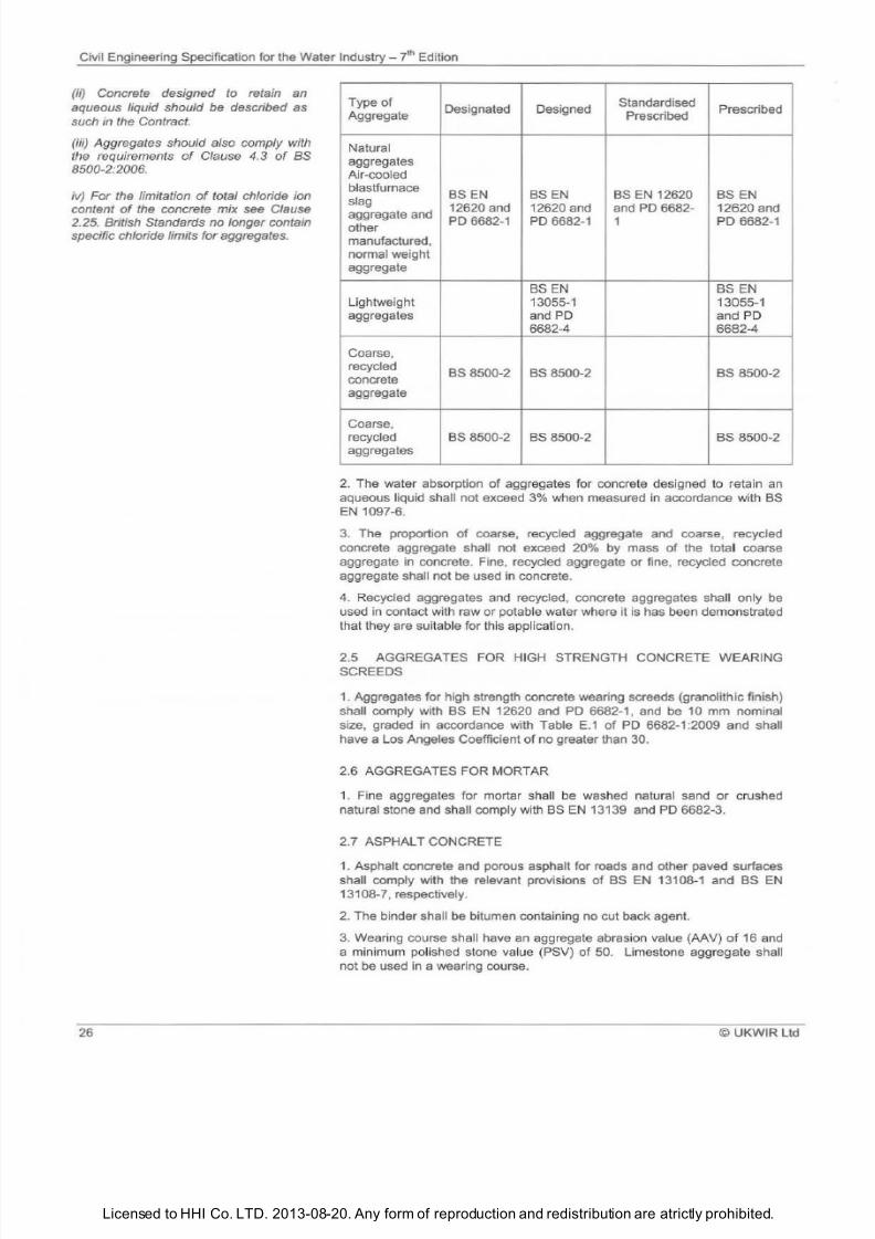
7/21/2019 The Civil Engineering Specification for the Water Industry 7th
http://slidepdf.com/reader/full/the-civil-engineering-specification-for-the-water-industry-7th 32/176Licensed to HHI Co. LTD. 2013-08-20. Any form of reproduction and redistribution are atrictly prohibited.
Civil Engineering Specification for the Water
Industry
i Edition
ii) Concrete designed to retain an
aqueous liquid should be described as
such in the Contract.
iii)
Aggregates should also comply with
the requirements o Clause 4.3 o BS
8500-2:2006.
iv)
For the limitation o total chloride ion
content o the concrete mix see Clause
2.25. British Standards no longer contain
specific chloride limits for aggregates.
26
Type
of
Designated Designed
Standardised
Prescribed
Aggregate Prescribed
Natural
aggregates
Air-cooled
blastfurnace BS
EN
BS
EN
BS EN 12620 BS EN
slag
12620 and 12620 and and
PO
6682- 12620 and
aggregate and
PO
6682-1
PO
6682-1 1
PO
6682-1
other
manufactured,
normal weight
aggregate
BSEN BS EN
Lightweight 13055-1
13055-1
aggregates and PO and PO
6682-4 6682-4
Coarse,
recycled
BS 8500-2 BS 8500-2 BS 8500-2
concrete
aggregate
Coarse,
recycled
BS
8500-2
BS
8500-2 BS 8500-2
aggregates
2 The water absorption of agg regates for concrete designed to retain an
aqueous liquid shall not exceed 3 when measured in accordance with BS
EN
1097-6.
3 The proportion of coarse, recycled aggregate and coarse, recycled
concrete aggregate shall not exceed 20 by mass
of
the total coarse
aggregate in concrete. Fine, recycled aggregate or fine, recycled concrete
aggregate shall not be used in concrete.
4 Recycled aggregates and recycled, concrete aggregates shall only be
used
in contact with raw or potable water where it is has been demonstrated
that they are suitable for this application.
2.5 AGGREGATES FOR HIGH STRENGTH CONCRETE WEARING
SCREEDS
1
Aggregates for high strength concrete wearing screeds (granolithic finish)
shall comply with
BS EN
12620 and
PO
6682-1 , and be 10 mm nominal
size, graded in accordance with Table
E 1 of PO
6682-1:2009 and shall
have a Los Angeles Coefficient of no greater than 30.
2.6 AGGREGATES FOR MORTAR
1
Fine aggregates for mortar shall be washed natural sand or crushed
natural stone and shall comply with BS EN 13139 and
PO
6682-3.
2.7 ASPHALT CONCRETE
1 Asphalt concrete and porous asphalt for roads and other paved surfaces
shall comply with the relevant provisions of BS EN 13108-1 and BS EN
13108-7, respectively.
2
The binder shall be bitumen containing no cut back agent.
3 Wearing course shall have an aggregate abrasion value (AAV)
of
16 and
a minimum polished stone value (PSV)
of
50. Limestone aggregate shall
not
be
used in a wearing course.
©
UKWIR Ltd
7/21/2019 The Civil Engineering Specification for the Water Industry 7th
http://slidepdf.com/reader/full/the-civil-engineering-specification-for-the-water-industry-7th 33/176Licensed to HHI Co. LTD. 2013-08-20. Any form of reproduction and redistribution are atrictly prohibited.
Civil Engineering Specification for the Water
Industry
tn Edition
i) The type
of
media and its nominal
size and grading should be described in
the Contract.
ii)
Appendix E
of as 1438:2004 gives
recommendations for the placing
of
ilter
media.
iii)
An
additional specification
will
be
required
for
a filter media other than
those covered by s 1438.
i) The required type, grade and
thickness
o
board should be described
in the Contract.
ii) Rigid urethane foam boards should
be CFC free.
©UKWIR
Ltd
2.8 BIOLOGICAL PERCOLATING FILTER MEDIA
1 Media for use in biological percolating filters from natural sources or
derived from the reduction
of
iron ore in a blastfurnace, shall comply with
the relevant provisions of BS 1438. All media for filter beds shall be washed,
graded and screened.
2 Grading
of
crushed rock (e.g., granite) or blastfurnace slag filter media
shall
be
either 75-40 mm or 63-40
mm
A further screening at
20
mm mesh
size shall
be
undertaken on Site as
the
media is placed. Material passing
through this screen shall not be used.
3
Structured modular crossflow media (PVC or polypropylene) products
shall be specifically designed for wastewater treatment. Media assembled
from sheets where the edges have been heat flanged shall not be used.
4
The media product shall be designed in such a way that it is:
(a) resistant to degradation from rot, fungi, and other forms of attack;
(b) chemically resistant to normal sewage, normally expected
concentrations
of
acids, alkalis and organic compounds;
(c) self extinguishing and compounded to be totally stable under the action
of
UV light.
5 Media modules shall be designed to:
(a)
be
100 crossflow media with no vertical or horizontal corrugations;
(b) have a specific surface area of 150 m
2
/m
3
with 25,000 mixing points per
cubic metre as a minimum and with a minimum 97 void to volume ratio;
(c) provide a minimum
of
70 open area at the pack to pack interface.
Horizontal surfaces shall not exceed a width
of 2 mm The media shall not
allow a drop of water to free fall more than 150 mm;
(d) be capable
of
redistributing wastewater horizontally a minimum
of
300
mm per 300 mm
of
media depth;
(e) allow the media to
be
structurally self-supporting with a minimum
bearing capacity of 1.5 kN/m
2
2.9 BITUMEN ROAD EMULSIONS
1 Bitumen road emulsions shall comply with the relevant provisions
of
BS
434-1.
2.10 BITUMINOUS COATINGS
1
Bituminous coatings shall comply with BS 3416.
2 11
BITUMINOUS JOINTING STRIP
1 Jointing strip for precast concrete tunnel and shaft segments shall be
bitumen based, 3
mm minimum thickness and be
su
itable for the size and
type of segments with which it is to be used. Where bolt holes are required,
they shall accurately match, in size and position,
the
corresponding holes in
the segments.
2.12 BOARDS FOR PANELLING
1
Boards for panelling shall comply with the relevant provisions
of
the
appropriate Standard, as set out in the following table:
27
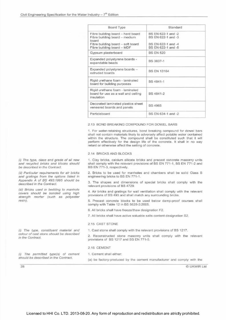
7/21/2019 The Civil Engineering Specification for the Water Industry 7th
http://slidepdf.com/reader/full/the-civil-engineering-specification-for-the-water-industry-7th 34/176Licensed to HHI Co. LTD. 2013-08-20. Any form of reproduction and redistribution are atrictly prohibited.
Civil Engineering Specification for the Water Industry th Edition
i) The type, class and grade o all new
and recycled bricks and blocks should
be described in the Contract.
ii) Particular requirements for air bricks
and gratings from the options listed in
Appendix A
o
BS 493:1995 should be
described in the Contract.
iii) Bricks used in bedding to manhole
covers should be bonded using high
strength mortar such as polyester
resin).
i) The type, constituent material and
colour o cast stone should be described
in the Contract.
i)
The
permitted type s)
o
cement
should be described in the Contract.
28
Board Type Standard
Fibre building board - hard board BS EN 622-1 and -2
Fibre building board - medium BS EN 622-1 and -3
board
Fibre bu
il
ding board soft board BS EN 622-1 and -4
Fibre building board - MDF BS EN 622-1 and -5
Gypsum plasterboard BS EN 520
Expanded polystyrene boards -
BS 3837-1
expandable beads
Expanded polystyrene boards -
BS EN 13164
extruded boards
Rigid urethane foam - laminated
board for building purposes
BS 4841-1
Rigid urethane foam - laminated
board for use as a wall and ceiling BS 4841-2
insulation
Decorated laminated plastics sheet
BS 4965
veneered boards and panels
Particleboard BS EN 634-1 and -2
2.13 BOND BREAKING COMPOUND FOR DOWEL BARS
1. For water-retaining structures, bond breaking compound for dowel bars
shall not contain materials likely to adversely affect potable water contained
within the structure. The compound shall be constituted such that it will
perform effectively for the design life of the concrete. It shall in no way
retard or otherwise affect the setting
of
concrete.
2.14 BRICKS AND BLOCKS
1. Clay bricks, calcium silicate bricks and precast concrete masonry units
sha
ll
comply with the relevant provisions
of
BS EN 771-1, BS EN 771-2 and
BS EN 771-3, respectively.
2 Bricks to be used for manholes and chambers shall be solid Class B
engineering bricks to BS EN 771-1.
3. The shapes and dimensions of special bricks shall comply with the
relevant provisions
of
BS 4729.
4 Air
bricks and gratings for wall ventilation shall comply with the relevant
provisions
of
BS 493 and shall match any surrounding bricks.
5
Precast concrete blocks to be used below damp-proof courses shall
comply with Table 12 in BS 5628-3:2005.
6 All bricks shall have freeze/thaw designation F2.
7. All bricks shall have active soluable salts content designation S2.
2.15 CAST STONE
1. Cast stone shall comply with the relevant provisions
of
BS 1217.
2 Reconstructed stone masonry units shall comply with the relevant
provisions
of
BS 1217 and BS EN 771-5.
2.16 CEMENT
1. Cement shall either:
a) be factory-produced by the cement manufacturer and comply with the
UKWIR Ltd
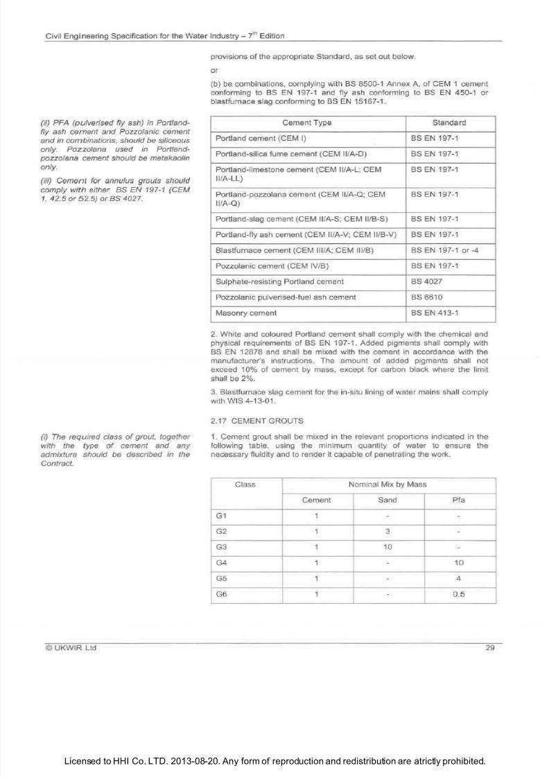
7/21/2019 The Civil Engineering Specification for the Water Industry 7th
http://slidepdf.com/reader/full/the-civil-engineering-specification-for-the-water-industry-7th 35/176Licensed to HHI Co. LTD. 2013-08-20. Any form of reproduction and redistribution are atrictly prohibited.
Civil Engineering Specification for the Water
Industry
? h Edition
ii) PFA pulverised fly ash} in Portland
fly
ash cement and
Pozzolanic cement
and
in combinations, should
be
siliceous
only. Pozzolana used in Portland
pozzolana cement should be metakaolin
only.
iii) Cement for annulus grouts should
comply with either BS EN 197-1 CEM
1,
42.5 or 5 .5) orBS 4027.
i)
The required class of grout, together
with the type of cement and any
admixture should be described m the
Contract.
© UKWIR Ltd
provisions of the appropriate Standard, as set out below.
or
(b) be combinations, complying with
8S
8500-1 Annex A,
of
CEM 1 cement
conforming to 8S
EN
1
97-1
and fly ash conforming to
BS EN
450-1 or
blastfurnace sl
ag
conforming to
BS EN
15167-1 .
Cement Type Standard
Portland cement (CEM I)
BS EN
197-1
Portland-silica fume cement
C EM
11/A-0) 8S
EN
197-1
Portland-limestone cement (CEM 11/A-L; CEM 8S
EN
197-1
II/A-LL)
Portland-pozzolana cement
C
EM 11A-Q; CEM
BS EN
197-1
11A-Q)
Portland-slag cement (CEM
11/A-S;
CEM
11/8-S)
8S
EN
197-1
Portland-fly ash cement
C EM 11/
A-V; CEM /8-V) 8S
EN
197-1
81astfumace cement (CEM Ill/A; CEM 11118)
8S
EN 197-1 or
4
Pozzolanic cement (CEM IV/B)
8S
EN 197-1
Sulphate-resisting Portland cement 8S 4027
Pozzolanic
pu
lverised-fuel ash cement 8S
66
10
Masonry cement 8S
EN
4
13
-1
2. White and coloured Portland cement shall comply with the chemical and
physical requirements
of
BS EN
197-1 . Added pigments shall comply with
8S
EN
12878 and shall be mixed with the cement in accordance with the
manufacturer's Instructions. The amount
of
added pigments shall not
exceed 10 of cement by mass, except for carbon black where the limit
shall be 2 .
3. Blastfurnace slag cement for the in-situ lining of water mains shall comply
with WIS 4-13-01.
2.17 CEMENT GROUTS
1. Cement grout shall be mixed in the relevant proportions indicated in the
following table, using the minimum quantity of water to ensure the
necessary fluidity and to render it capable of penetrating the work.
Class Nominal Mix by Mass
Cement Sand
Pfa
G1
1
G2 1 3
G3 1 10
-
G4 1 10
G5
1
4
G6 1 0.5
29
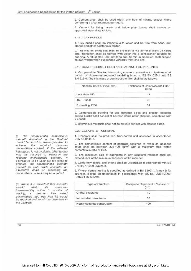
7/21/2019 The Civil Engineering Specification for the Water Industry 7th
http://slidepdf.com/reader/full/the-civil-engineering-specification-for-the-water-industry-7th 36/176Licensed to HHI Co. LTD. 2013-08-20. Any form of reproduction and redistribution are atrictly prohibited.
Civil Engineering Specification for the Water Industry - 7
1
h Edition
i) The
characteristic compressive
strength described
in
the Contract
should
be
selected, where possible,
to
achieve the required mtmmum
cementitious content. f the relevant
information
is
not available, initial testing
may
be
required to establish the
required characteristic strength. f
aggregates
to be
used are too weak
to
produce the characteristic strength
needed for high grade concrete, an
alternative basis of assessing the
cementitious content may
be
required.
ii)
Where
it is important that concrete
should attain its maximum
impermeability within 6 months of
placing,
a
maximum free water/
cementitious ratio less than 0.6 would
be
required and should
be
described
in
the Contract.
30
2. Cement grout shall be used within one hour
of
mixing, except where
containing a grout retardant admixture.
3. Cement for fixing inserts and below plant bases shall
inc
lude an
approved expandi
ng
additive.
2.18 CLAY PUDDLE
1.
Clay puddle shall
be
impervious to water and
be
free from sand, grit,
stones and other deleterious matter.
2. The clay on being dug shall
be
exposed to the air for at least
24
hours
and, thereafter, shall be worked with water into a consistency suitable for
punning. A roll of clay, 300 mm long and 40 mm in diameter, shall support
its own weight when suspended vertically from one end.
2.19 COMPRESSIBLE FILLER AND PACKING FOR PIPELINES
1
Compressible filler for interrupting concrete protection to pipelines shall
consist of bitumen-impregnated insulating board to
BS
EN 622-1 and BS
EN
622-4. The thickness of compressible filler shal l be
as
follows:
Nominal Bore of Pipe mm) Thickness
of
Compressible Filler
mm)
Less than 450
18
450 1200
36
Exceeding 1200
54
2. Compressible packing for use between pipes and precast concrete
setting blocks shall consist of bitumen damp-proof sheeting, complying with
BS 6398.
3. Bituminous materials shall not be put into contact with plastics pipes.
2.20
CONCRETE - GENERAL
1
Concrete shall be produced, transported and accessed in accordance
with
BS
8500-2.
2 The cementitious content of concrete designed to retain an aqueous
liquid shall be between 325-400 kg/m
3
with a maximum free water/
cementitious ratio
of
0.55 .
3. The maximum size of aggregate in any structural member shall not
exceed 25 of the minimum thickness
of
the member.
4 Conformity control and criteria shall be undertaken in accordance with
BS
EN
206-1 :2000
Clause
8.
5. Where identity testing is specified as defined in
BS
8500-1, Annex B for
strength, it shall
be
undertak
en
in accordance with BS
EN
206-1 :2000,
Annex B as
fol
lows:
Type of Structure Sample to Represent a Volume of
m3)
Critical structures
10
Intermediate structures
50
Heavy concrete construction
100
©UKW R Ltd
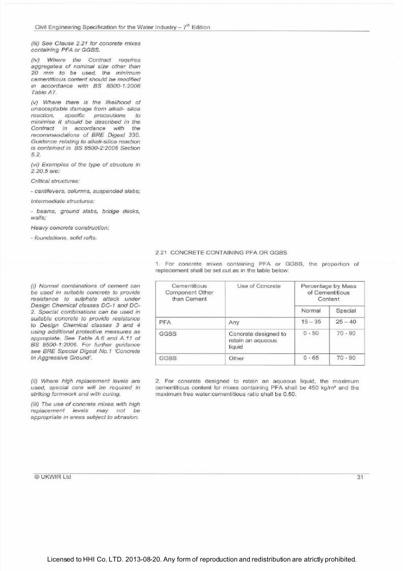
7/21/2019 The Civil Engineering Specification for the Water Industry 7th
http://slidepdf.com/reader/full/the-civil-engineering-specification-for-the-water-industry-7th 37/176Licensed to HHI Co. LTD. 2013-08-20. Any form of reproduction and redistribution are atrictly prohibited.
Civil Engineering Specification for the Water Industry - 7hEdition
(iii) See Clause 2.21 for concrete mixes
containing PFA or GGBS.
(iv) Where the Contract requires
aggregates of nominal size other than
20 mm to be used, the minimum
cementitious content should be modified
in accordance
with
BS 8500-1:2006
Table
Al
v) Where there is the likelihood of
unacceptable damage from alkali- silica
reaction, specific precautions to
minimise it should be described in the
Contract in accordance with the
recommendations
of
BRE Digest 330.
Guidance relating to alkali-silica reaction
is
contained in BS 8500-2:2006 Section
5.
2.
(vi) Examples of the type of structure in
2.20.5 are:
Critical structures:
- cantilevers, columns, suspended slabs;
Intermediate structures:
- beams, ground slabs, bridge decks,
walls;
Heavy concrete construction:
- foundations, solid rafts.
i)
Normal combinations of cement can
be used in suitable concrete to provide
resistance to sulphate attack under
Design Chemical classes DC-1 and DC-
2. Special combinations can be used in
suitable concrete
to
provide resistance
to Design Chemical classes and 4
using additional protective measures
as
appropiate. See Table A.6 and A.11
of
BS 8500-1:2006. For further guidance
see BRE Special Digest
No.1
Concrete
In Aggressive Ground .
(ii) Where high replacement levels are
used, special care will be required in
striking formwork and
with
curing.
(iii) The use
of
concrete mixes with high
replacement levels may not be
appropriate in areas subject to abrasion.
©
UKWIR Ltd
2.21 CONCRETE CONTAINING PFA OR GGBS
1.
For concrete mixes containing PFA or GGBS the proporti
on
of
replacement sha ll
be
set out
as
in the table below:
Cementitious Use
of
Concrete
Percentage
y
Mass
Component Other
of
Cementitious
than Cement Content
Normal
Special
PFA Any
15 35
25 40
GGBS Concrete designed to
0 50
70 90
retain
an
aqueous
liquid
GGBS Other
0 65 70 90
2.
For concrete designed to retain
an
aqueous liquid the maximum
cementitious content for mixes containing PFA sha ll be
450
kg/m
3
and the
maxi
mum
free water:cementitious ratio shall
be
0 50
3
7/21/2019 The Civil Engineering Specification for the Water Industry 7th
http://slidepdf.com/reader/full/the-civil-engineering-specification-for-the-water-industry-7th 38/176Licensed to HHI Co. LTD. 2013-08-20. Any form of reproduction and redistribution are atrictly prohibited.
Civil Engineering Specification for the Water I
ndustry
ylh Edition
i) ny restrictions on the use
of
ready
mixed concrete in the Works should be
described in the Contract.
ii) A coded description for the concrete,
to
obviate unnecessary repetition
of
items upon delivery tickets, may be
acceptable.
iii) ny requirements for infor- mation
concerning the taking of test cubes or
slump or other consistence
determinations, should be described in
the Contract.
iv) ny restrictions on the use of
admixtures in the Works should be
described
in
the Contract.
i)
Air-entraining admixtures used in
conjunction with PFA can give rise to
very variable air content.
i) Particular requirements from the
options listed in BS EN 1916 and BS
5911-1 should be described in the
Contract.
ii) Additional protective measures
required by BRE Special Digest No.1 to
provide resistance to the actual ACEC
Aggressive Chemical Environment for
Concrete class) should be described in
the
Contract.
32
2.22 CONCRETE- READY-MIXED
1.
Where concrete is to
be
obtained from a ready-mix supplier, the
supplying plant shall be approved by a Third Party Certification body
accredited by the United Kingdom Accreditation Service UKAS) for product
conformity.
2. The de
li
very ticket requir
ed
for each load
of
ready-mixed concrete shall ,
in addition to the information prescribed under
BS EN
206 1 :2000 Clause
7.3, detail:
a) the type
of
aggregate;
b) the actual cementitious content and the percentage
of
any P
FA
or
GGBS included; and
c) the position
of
the concrete in the Works details to be inserted
at
the
point
of
discharge).
3.
All delivery tickets sha ll be kept
at
the Site and shall
be
made available
for inspecti
on
2.23 CONCRETE - POROUS NO-FINES
1. Porous no-fines concrete shall contain CEM 1 cement to BS EN 197 1 ,
and 20-10
mm
aggregate complying with
BS EN 12
620 and
PO
6682-1, in a
proportion
of
1:10
by
mass.
2.
The concrete shall
be
mixed to a uniform colour and consistency, with the
addition
of
water sufficient on ly to coat all
of
the aggregate without forming
excess grou
t.
2.24 CONCRETE - AIR-ENTRAI NED
1.
Air-entrai ned concrete sha ll have a minimum air content by volume
of
the
fresh concrete
at
the time
of
placing, in accordance with
BS
8500-1:2006
Table A.8.
2.25 CONCRETE - CHLORIDE CONTENT
1. Ch loride content of fresh concrete shall be determined in accordance with
BS EN
206-1:2000 Clause 5.2.7.
2. Methods for determining the ch loride contents of constituent materials
shall
be
in accordance with
BS
8500-2.
2.26 CONCRETE- PIPES AND FITTINGS
1. Unreinforced and reinforced concrete pipes and fittings shall comply with
the relevant provisions of BS EN 1916 and BS 5911-1.
2. All pipes and fittings shall have gasket-type joints
of
spigot and socket or
rebated form.
3. Unreinforced and reinforced concrete jacking pipes shall comply with the
relevant provisions
of BS
EN 1916
and BS
5911-1. Pipes shall withstand
the jacking loads to which they wil l be subjected during instal lation, without
cracking or spalling. A certificate shall be supplied to the Client, confirming
that the pipes are suitable for jacking
and
stating the distributed jacking
loads for which th ey were designed.
2.27 CONNECTORS FOR TIMBER
1. Connectors for timber shall comply with the relevant provisions of BS EN
912.
UKWIR Ltd
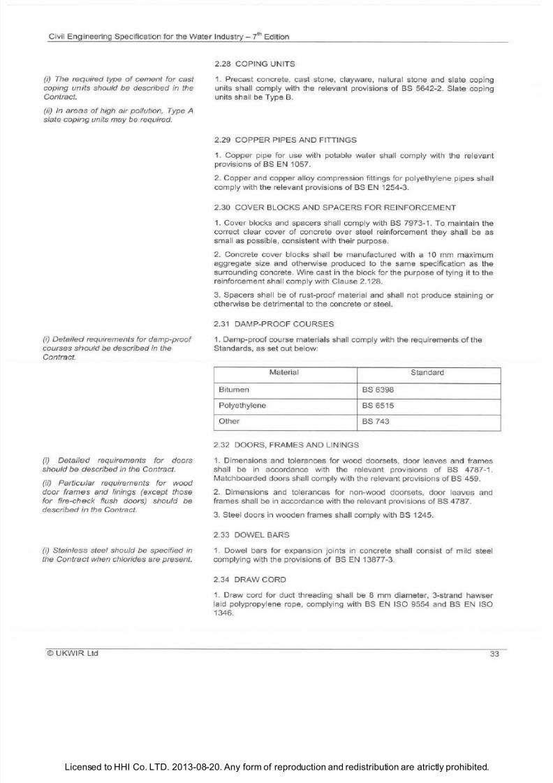
7/21/2019 The Civil Engineering Specification for the Water Industry 7th
http://slidepdf.com/reader/full/the-civil-engineering-specification-for-the-water-industry-7th 39/176Licensed to HHI Co. LTD. 2013-08-20. Any form of reproduction and redistribution are atrictly prohibited.
Civil Engineering Specification for the Water I
ndustry i
Edition
i) The required type of cement for cast
coping
units
should be described in the
Contract.
ii) In areas
of
high air pollution, Type A
slate
coping
units may be required.
i) etailed requirements fo r damp-proof
courses
should
be described in the
Contract.
i)
etailed
requirements for doors
should
be
described in the Contract.
ii) Particular requirements for wood
door frames and linings except those
for fire-check flush doors) should be
described in the Contract.
i) Stainless steel should be specified in
the Contract when chlorides are present.
UKWIR Ltd
2.28 COPING UNITS
1
Precast concrete cast stone clayware natural stone and slate coping
units shall comply with the relevant provisions
of
BS 5642-2. Slate coping
units shall be Type
B
2.29 COPPER PIPES AND FITTINGS
1
Copper p
ip
e for use with potable water shall comply with the relevant
provisions
of BS EN
1057.
2
Copper and copper alloy compression fittings for polyethylene pipes shall
comply with the relevant provisions
of BS EN
1254-3
2.30 COVER BLOCKS AND SPACERS FOR REINFORCEMENT
1 Cover blocks and spacers shall comply with BS 7973-1. To maintain the
correct clear cover
of
concrete over steel reinforcement they shall be as
small
as
possible consistent with their purpose.
2 Concrete cover blocks shall
be
manufactured with a 10
mm
maximum
aggregate size
and
otherwise produced
to
the same specification as the
surrounding concrete. Wire cast in the block for the purpose
of
tying it to the
reinforcement shall comply with Clause 2.128.
3 Spacers shall be
of
rust-proof material and shall not produce staining or
otherwise
be
detrimental to the concrete or steel.
2 31 DAMP-PROOF COURSES
1. Damp-proof course materials shall comply with the requirements of the
Standards as set out below:
Material
Standard
Bitumen
BS 6398
Polyethylene
BS 6515
Other
BS
743
2.32 DOORS FRAMES AND LININGS
1 Dimensions and tolerances for wood doorsets door leaves and frames
shall be in accordance with the relevant provisions of BS 4787-1.
Matchboarded doors shall comply with the relevant provisions
of BS
459.
2. Dimensions and tolerances for non-wood doorsets door leaves and
frames shall
be
in accordance with the relevant provisions
of BS
4787.
3 Steel doors
in
wooden frames shall comply with BS 1245.
2.33 DOWEL BARS
1 Dowel bars for expansion joints in concrete shall consist
of
mild steel
complying with the provisions
of
BS EN 13877-3.
2.34 DRAW CORD
1 Draw cord for duct threading shall be 8 mm diameter 3-strand hawser
laid polypropylene rope complying with BS
N
ISO 9554 and BS
EN
ISO
1346.
33
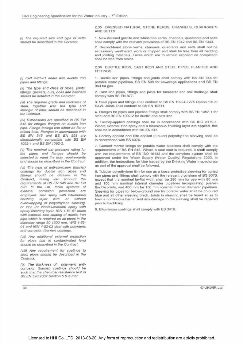
7/21/2019 The Civil Engineering Specification for the Water Industry 7th
http://slidepdf.com/reader/full/the-civil-engineering-specification-for-the-water-industry-7th 40/176Licensed to HHI Co. LTD. 2013-08-20. Any form of reproduction and redistribution are atrictly prohibited.
Civil Engineering Specification for the Water Industry J h Edition
i) The required size and type
of
seNs
should be described in the Contract.
i)
IGN 4-21-01 deals with ductile iron
pipes and fittings.
ii)
The
type and class
of
pipes, joints,
fittings, gaskets, nuts, bolts and washers
should be detailed in the Contract.
iii) The required grade and thickness
of
steel, together with the type and
strength of pipe, should be described in
the Contract.
iv) Dimensions are specified in as EN
545 for integral flanges on ductile iron
pipe. Flange facings can either be flat or
raised
face.
Flanges in accordance
with
as EN 545 and as EN 598 are
dimensionally compatible with as EN
1092-1 and
as
EN 1092-2.
v) The nominal bar pressure rating for
the pipes and flanges should be
selected to meet the duty requirements
and should be described in the Contract.
vi) The type of anti-corrosion barrier)
coatings for ductile iron pipes and
fittings should be detailed in the
Contract, taking into account the
requirements of as EN 545 and as EN
598. In the UK, three systems of
external corrosion protection are
employed: zinc spray with bituminous
finishing layer with or without
overwrapping of polyethylene sfeeving,
or zinc or zinc/aluminium) spray with
epoxy finishing layer. IGN 4-51-01 deals
with external zinc coating
of
ductile iron
pipe which is required on all pipes in the
diameter range 80-1600 mm
WIS
4-52-
01
and IGN 4-52-02 deaf with polymeric
anti-corrosion barrier) coatings.
vii) Any additional external protection
for pipes laid in contaminated land
should be described
in the Contract.
viii) ny requirement for coatings to
steel pipes should be described in the
Contract.
ix) The
thickness
of
polymeric anti
corrosion barrier) coatings should be
such that the chemical resistance test in
as
EN 598:2007 Section 5.6
is
met.
34
2.35 DRESSED NATURAL STONE KERBS, CHANNELS, QUADRANTS
ANDSETIS
1 New dressed granite and whinstone kerbs, channels, quadrants and setts
shall comply with the relevant provisions of BS EN 1342 and BS EN 1343.
2
Second-hand stone kerbs, channels, quadrants and setts shall not
be
excessively weathered, worn or chipped and shall be free from all bedding
and jointing materials. Faces which are to remain exposed on completion
shall be free from stains.
2.36 DUCTILE IRON, CAST IRON AND STEEL PIPES. FLANGES AND
FITIINGS
1 Ductile iron pipes, fittings and joints shall comply with BS EN 545 for
potable water pipelines, BS
EN
598 for sewerage applications and BS
EN
969 for gas.
2 Cast iron pipes, fittings and joints for ra inwater and soil drainage shall
comply with BS EN 877.
3
Steel pipes and fittings sha ll conform to BS EN 10224-L275 Option 1 S or
SAW. Joints shall conform to BS EN 10311.
4. Flanges for pipes and pipeline fittings shall comply with BS EN 1092-1 for
steel and BS EN 1092-2 for ductile and cast iron.
5 Factory-applied coatings shall be in accordance with BS ISO 8179-1.
Where external zinc spray and a bituminous finishing layer are applied, this
shall be in accordance with BS
EN
545.
6
Factory-applied and Site-applied tubular) polyethylene sleeving shall
be
in accordance with BS 6076.
7
Cement mortar linings for potable water pipelines shall comply with the
requirements of BS EN 545. Where a seal coat is required, it shall comply
with the requirements of BS ISO 16132 and the complete system shall be
approved under
the
Water Supply Water Quality) Regulations 2000.
In
addition, the Instructions for Use issued by the Drinking Water Inspectorate
as part of the approval shall be followed.
8
Tubular polyethylene film for use as a loose protective sleeving for buried
iron pipes and fittings shall comply with the relevant provisions
of
BS 6076,
except that the nominal layflat width shall be 280 mm for use with
80 mm
and 100 mm nominal internal diameter pipelines incorporating push-in
flexible joints, and 400 mm for 150 mm nominal internal diameter pipelines.
Sleeving for pipes for below-ground use for potable water shall be coloured
blue and all other sleeving black. Joints in sleeving shall be taped so as to
form a continuous barrier and any damage to the sleeving shall
be repaired
prior to backfilling.
9
Bituminous coatings shall comply with
BS
3416.
©
UKWIR Ltd
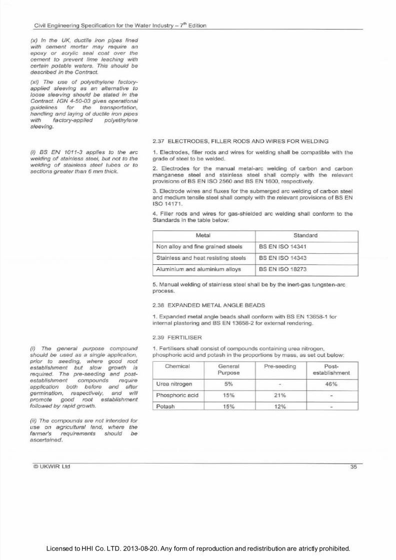
7/21/2019 The Civil Engineering Specification for the Water Industry 7th
http://slidepdf.com/reader/full/the-civil-engineering-specification-for-the-water-industry-7th 41/176Licensed to HHI Co. LTD. 2013-08-20. Any form of reproduction and redistribution are atrictly prohibited.
Civil Engineering Specification for the Water
Industry ih
Edition
(x) In the UK, ductile iron pipes lined
with cement mortar may require an
epoxy
or acrylic seal coat over the
cement to prevent lime leaching with
certain potable waters. Th is should be
described in the Contract.
(xi)
The
use of polyethylene factory
applied sleeving as an alternative to
loose sleeving should be stated in the
Contract. IGN 4-50-03 gives operational
guidelines for the transportation,
handling nd laying of ductile iron pipes
with factory-applied polyethylene
sleeving.
i) BS N 1011-3 applies to the arc
welding of stainless steel, but not to the
welding of stainless steel tubes or to
sections greater than 6 mm thick.
i) The
general purpose compound
should be used as a single application,
prior to seeding, where good root
establishment but slow growth is
required. The pre-seeding and post
establishment compounds require
application both before and after
germination, respectively, and will
promote good root establishment
followed by rapid growth.
(ii)
The
compounds are not intended for
use on agricultural land, where the
farmer s requirements should be
ascertained.
©UKWIR Ltd
2.
37
ELECTRODES, FILLER RODS AND WIRES FOR WELDING
1 Electrodes, fi ller rods and wires for welding shall be compatible with
the
grade
of
steel to be welded.
2 Electrodes for the manual metal-arc welding of carbon and carbon
manganese steel and stainless steel shall comply with the relevant
provisions of
BS EN
ISO 2560 and
BS EN
1600, respectively.
3 Electrode wires and fluxes for the submerged arc welding of carbon steel
and medium tensile steel shall comply with the relevant provisions of
BS EN
ISO 14171.
4. Filler rods and wires for gas-shielded arc welding shall conform to the
Standards in the table below:
Metal Standard
Non alloy and fine grained steels
BS EN
ISO 14341
Stainless and heat resisting steels
BS EN
ISO 14343
Aluminium and aluminium alloys
BS EN
ISO 18273
5
Manual welding of stainless steel shall
be
by
the In
ert-gas tungsten-arc
process.
2.38 EXPANDED METAL ANGLE BEADS
1 Expanded metal angle beads shall conform with BS EN 13658-1 for
internal plastering and BS EN 13658-2 for external rendering.
2.39 FERTILISER
1
Fertilisers shall consist of compounds containing urea nitrogen,
phosphoric acid and potash in the proportions by mass, as set out below:
Chemical General Pre-seeding
Post-
Purpose
establishment
Urea nitrogen
5 46
Phosphoric acid 15 21
Potash
15 12
35
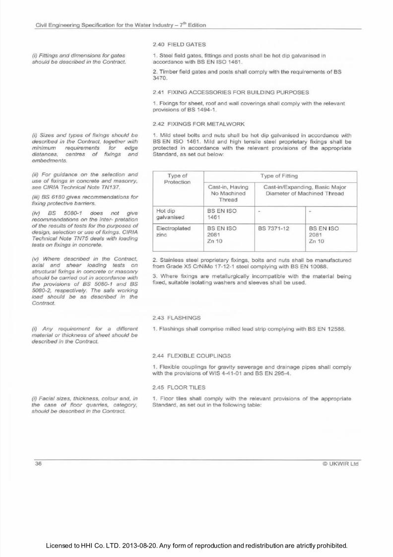
7/21/2019 The Civil Engineering Specification for the Water Industry 7th
http://slidepdf.com/reader/full/the-civil-engineering-specification-for-the-water-industry-7th 42/176Licensed to HHI Co. LTD. 2013-08-20. Any form of reproduction and redistribution are atrictly prohibited.
Civil Engineering Specification for the Water
Industry
7t Edition
i) Fittings and dimensions for gates
should be described in the Contract.
i) Sizes and types of fixings should be
described in the Contract, together with
minimum requirements for edge
distances, centres of fixings and
embedments.
ii) For guidance on the selection
and
use of fixings in concrete and masonry,
see CIRIA Technical Note TN137.
iii) as 6180 gives recommendations for
fixing protective barriers.
iv) as 5080-1 does not give
recommendations on the inter- pretation
of
the results
of
ests for the purposes
of
design, selection
or
use of ixings. CIRIA
Technical Note TN75 deals with loading
tests on
fixings in concrete.
{v) Where described in the Contract,
axial
and shear
loading
tests
on
structural fixings in concrete
or
masonry
should be carried out in accordance with
the provisions
of
as 5080-1 and as
5080-2, respectively.
The
safe working
load should be as described in the
Contract.
{i ny requirement for
a
different
material
or
thickness
of
sheet should be
described in the Contract.
i) Facial sizes, thickness, colour
and
, in
the case of floor quarries, category,
should be described in the Contract.
36
2.40 FIELD GATES
1. Steel field gates fittings and posts shall be hot dip galvanised in
accordance with BS
EN
ISO 1461.
2. Timber field gates and posts shall comply with the requirements of BS
3470.
2.41 FIXING ACCESSORIES FOR BUILDING PURPOSES
1. Fixings for sheet roof and wall coverings shall comply with the relevant
provisions
of
BS 1494-1 .
2.42 FIXINGS FOR METALWORK
1. Mild steel bol
ts
and nuts shall be hot dip galvanised in accordance with
BS EN ISO 1461. Mild and high tensile steel proprietary fixings shall be
protected in accordance with the relevant provisions
of
the appropriate
Standard as set out below:
Type of
Type of Fitting
Protection
Cast-in Having Cast-in/Expanding Basic Major
No Machined Diameter
of
Machined Thread
Thread
Hot dip BS EN ISO
galvanised
1461
Electroplated BS EN ISO BS 7371-12
BS EN ISO
zinc 2081
2081
Zn 10 Zn 10
2. Stainless steel proprietary fixings bolts and nuts shall be manufactured
from Grade X5 CrNiMo 17-12-1 steel complying with BS
EN 10088.
3
Where fixings are metallurgica
ll
y incompatible with the material being
fixed suitable isolating washers and sleeves sha ll be used.
2.43 FLASHINGS
1. Flashings shall comprise milled lead st rip complying with BS EN 12588.
2.44 FLEXIBLE COUPLINGS
1. Flexible couplings for gravity sewerage and drainage pipes shall comply
with the provisions
of
WIS 4-41-01 and BS EN 295-4.
2.45 FLOOR TILES
1. Floor tiles shall comply with the relevant pro
vi
sions
of
the appropriate
Standard as set out in the following table:
© UKWIR Ltd
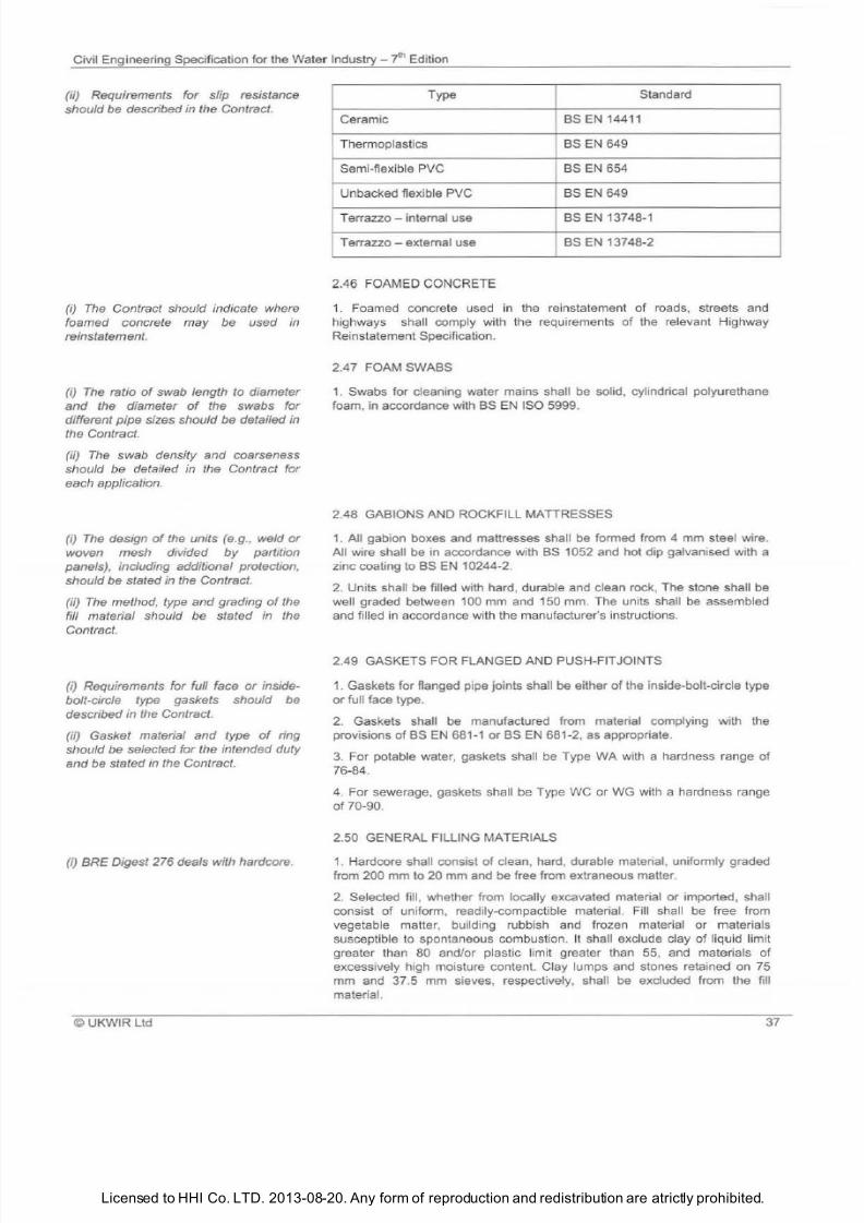
7/21/2019 The Civil Engineering Specification for the Water Industry 7th
http://slidepdf.com/reader/full/the-civil-engineering-specification-for-the-water-industry-7th 43/176Licensed to HHI Co. LTD. 2013-08-20. Any form of reproduction and redistribution are atrictly prohibited.
Civil Engineering Specification for the Water Industry
? h
Edition
ii) Requirements for slip resistance
should be described in the Contract.
i) The
Contract should indicate where
foamed concrete may be used
in
reinstatement.
i) The
ratio of swab length to diameter
nd the diameter of the swabs for
different pipe sizes should be detailed in
the Contract.
ii)
The
swab density and coarseness
should be detailed in the Contract for
each application.
i) The
design of the units e.g., weld or
woven mesh divided
by
partition
panels), including additional protection,
should be stated in the Contract.
ilj
The
method, type and grading of the
fill material should be stated in the
Contract.
i)
Requirements for full face or inside
bolt-circle type gaskets should be
described in the Contract.
ii) Gasket material and type
of
ring
should be selected
for
the intended duty
and be stated in the Contract.
i) BRE Digest 276 deals with hardcore.
© UKWIR Ltd
Type Standard
Ceramic
BSEN14411
Thermoplastics BS EN 649
Semi-flexible PVC
BS EN
654
Unbacked flexible PVC
BS EN
649
Terrazzo internal use BS EN 13748-1
Terrazzo - external use
BS
EN
13748-2
2.46 FOAMED CONCRETE
1. Foamed concrete used
in
the reinstatement of roads, streets and
highways shall comply with the requirements of the relevant Highway
Reinstatement Specification.
2.47 FOAM SWABS
1.
Swabs for cleaning water mains shall be solid, cylindrical polyurethane
foam,
in
accordance with BS EN ISO 5999.
2.48 GABIONS
AND
ROCKFILL MA
DRESSES
1. All gabion boxes and mattresses shall be formed from 4 mm steel wire.
All wire shall be in accordance with
BS
1052 and hot dip galvanised with a
zinc coating to
BS EN
10244-2.
2 Units shall be filled with hard, durable and clean rock, The stone shall be
well graded between
100
mm and 150
mm.
The units shall be assembled
and filled in accordance with the manufacturer s instructions.
2.49 GASKETS
FOR
FLANGED AND PUSH-FITJOINTS
1. Gaskets for flanged pipe joints shall be either of the inside-bolt-circle type
or full face type.
2. Gaskets shall be manufactured from material complying with the
provisions of BS EN 681-1 orBS EN 681-2, as appropriate.
3.
For potable water, gaskets shall
be
Type WA with a hardness range of
76-84.
4. For sewerage, gaskets shall be Type WC or
WG
with a hardness range
of 70-90.
2.50 GENERAL FILLING MATERIALS
1. Hardcore shall consist of clean, hard, durable material, uniformly graded
from 200 mm to 20 mm and be free from extraneous matter.
2 Selected fill , whether from locally excavated material or imported, shall
consist of uniform, readily-compactible material. Fill shall be free from
vegetable matter, building rubbish and frozen material or materials
susceptible
to
spontaneous combustion. It shall exclude clay of liquid limit
greater than 80 and/or plastic
li
mit greater
than 55
and materials of
excessively high moisture content. Clay lumps and stones retained on 75
mm and 37.5 mm sieves. respectively, shall
be
excluded from the fill
material.
37
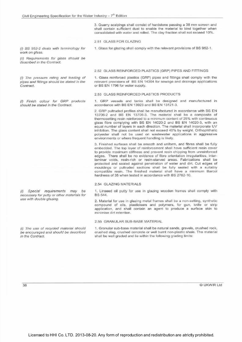
7/21/2019 The Civil Engineering Specification for the Water Industry 7th
http://slidepdf.com/reader/full/the-civil-engineering-specification-for-the-water-industry-7th 44/176Licensed to HHI Co. LTD. 2013-08-20. Any form of reproduction and redistribution are atrictly prohibited.
Civil Engineering Specification for the Water Industry J h Edition
i)
BS 952-2 deals with terminology for
work on glass.
ii) Requirements for glass should be
described in the Contract.
{i) The
pressure rating and loading
o
pipes and fittings should be stated in the
Contract.
i)
Finish colour for GRP products
should be stated in the Contract.
i) Special requirements may
be
necessary for putty or other materials for
use
with double glazing.
i) The
use o recycled material should
be encouraged and should be described
in the Contract.
38
3 Quarry scalpings shall consist of hardstone passing a 38 mm screen and
shall contain sufficient dust to enable the material to bind together when
consolidated with water and rolled. The clay fraction shall not exceed 10 .
2 51 GLASS FOR GLAZING
1 Glass for glazing shall comply with the relevant provisions of BS 952-1.
2.52 GLASS REINFORCED PLASTICS (GRP) PIPES AND FITTINGS
1
Glass reinforced plastics (GRP) pipes and fittings shall comply wi
th
the
relevant provisions of BS EN 14364 for sewage and drainage appl ications
or BS EN 1796 for water supply.
2.53 GLASS REINFORCED PLASTICS PRODUCTS
1 GRP vessels and tanks shall be designed and manufactured in
accordance with
BS
EN
13923 and
BS EN
13121-3.
2
GRP pultruded profiles sha
ll
be manufactured in accordance with BS EN
13706-2 and BS EN 13706-3. The material shall be a composite of
thermosett i
ng
resin reinforced to a minimum content of 25 with continuous
glass fibre complying with
BS EN
14020-2
and BS EN
14020-3, with an
equal number of layers in each direction. The material shall incorporate UV
inhibition. The glass content shall not exceed 40 by weight. Orthophthalic
polyester
sha
ll not be used on wastewater applications
in
aggressive
environments or where frequent handling is likely.
3 Finished surfaces shall be smooth
and
uniform, and fibres shall be fully
embedded. The top layer of reinforcement sha
ll
have sufficient resin cover
to provide maximum stiffness and prevent resin chipping from unreinforced
edges. There shall be no evidence of fibre orientation irregularities, inter
laminar voids, resin-rich or resin-starved areas. Fabrications shall be
protected and sea led against penetration of water and dirt. Cut edges of
mouldings or pultruded sections sha ll be fully sealed with a suitably
compatible resin. The finished material shall have a minimum Barcol
hardness of 35 when tested
in
accordance with
BS
2782-10.
2.54 GLAZI
NG
MATERIALS
1 Linseed oil putty for use in glazing wooden frames shall comply with
BS 544.
2. Material for use
in
glazing metal frames shall be a non-setting, synthetic
compound of o
il
s, plasticisers and polymers, for gun, knife or strip
application, and shall contain an agent to produce a surface skin to
minimise dirt retention.
2.55 GRANULAR SUB-BASE MATERI
AL
1
Granular sub-base material sha ll be natural sands, gravels, crushed rock,
crushed slag, crushed concrete or well burnt non-plastic shale. The material
sha
ll
be well graded and lie within the fol lowing grading limits:
© UKWIR Ltd
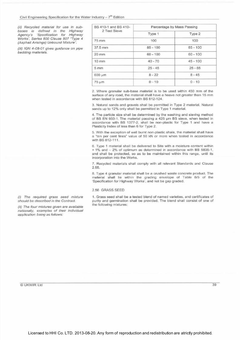
7/21/2019 The Civil Engineering Specification for the Water Industry 7th
http://slidepdf.com/reader/full/the-civil-engineering-specification-for-the-water-industry-7th 45/176Licensed to HHI Co. LTD. 2013-08-20. Any form of reproduction and redistribution are atrictly prohibited.
Civil Engineering Specification for the Water Industry - 7
t
Edition
(ii) Recycled material for use in sub
bases
is defined in the Highway
Agency's 'Specification for Highway
Works , Series BOO Clause 807 Type 4
(Asphalt Arisings) Unbound Mixture .
(iii)
IGN
4 08
- 1 gives guidance on pipe
bedding materials.
(i) The required
grass
seed mixture
should be described in the Contract.
(ii)
The
four
mixtures given are available
nationally, examples
of
their individual
application being as follows:
UKWIR Ltd
BS 410 1 and BS 410- Percentage by Mass Passing
2 Test Sieve
Type 1 Type 2
75mm 100 100
37.5
mm
85 100
85
- 100
20mm
60 100
60
100
10mm
40 70 45 - 100
5mm
25 45
25 85
600
~
8 - 22 8 45
75
0
10 0 - 10
2. Where granular sub-base material is to
be
used within 450 mm of the
surface
of
any road, the material shall have a heave not greater than 15 mm
when tested
in
accordance with
BS
812-124.
3.
Natural sands and gravels shall be permitted in Type 2 material. Natural
sands up to 12% only shall be permitted in Type 1 material.
4. The particle size shall
be
determined by the washing and sieving method
of
BS EN
933 1 . The material passing a 425
~ BS
sieve, when tested in
accordance with BS 1377-2, shall be non-plastic for Type 1 and have a
Plasticity Index of less than 6 for Type 2.
5.
With the exception of well burnt non-plastic shale, the material shall have
a ten per cent fines value of 50 kN or more when tested
in
accordance
with BS
812-111 .
6. Type 1 material shall
be
delivered to Site with a moisture content within
+
1%
and
2%
of
optimum as determined in accordance with
BS
5835-1 ,
and shall be protected, so as to be maintained within th is range, until its
incorporation into the Works.
7.
Recycled materials shall comply with all relevant Standards and Clause
2.55.
8.
Type 4 granular material shall be a crushed waste concrete product. The
material sha ll lie within the grading envelope
of
Table 8/5
of
the
'Specification for Highway Works', and not be gap graded.
2.56
GRASS
SEED
1.
Grass seed shall
be
a tested blend of named varieties, and certificates of
purity and germination shall be provided. The blend shall consist
of
one of
the following mixtures:
39
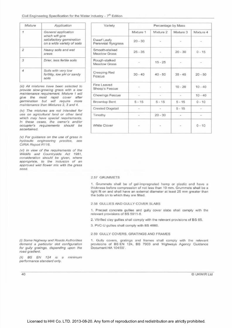
7/21/2019 The Civil Engineering Specification for the Water Industry 7th
http://slidepdf.com/reader/full/the-civil-engineering-specification-for-the-water-industry-7th 46/176Licensed to HHI Co. LTD. 2013-08-20. Any form of reproduction and redistribution are atrictly prohibited.
Civil Engineering Specification for the Water
Industry ?h
Edition
Mixture Application
1
General application
which will give
satisfactory germination
on a wide variety
of
soils
Heavy
soils
and wet
areas
3 Drier, less fertile soils
4 Soils with very low
fertility, low
p
or sandy
soils
iii) All mixtures have been selected to
provide slow-growing grass with a low
maintenance requirement. Mixture 1 will
give the most rapid cover after
germination but will require more
maintenance than Mixtures 2, 3 and 4.
iv)
The
mixtures are not intended for
use on agricultural land or other land
which may have special requirements.
In
these cases, the owner s and/or
occupier s requirements should be
ascertained.
(
v)
For guidance on the use of grass in
hydraulic engineering practice, see
CIRIA Report R116.
(v
i)
In
view
of
the requirements
of
the
Wildlife and Countryside Act 1981 ,
consideration should be given, where
appropriate. to the inclusion of an
approved wild flower mix with the grass
seed.
i) Some Highway and Roads Authorities
demand a particular slot configuration
for gully gratings, depending upon
the
road gradient.
(ii) BS EN
124
is a minimum
performance standard only.
Variety Percentage by Mass
Mixture
1
Mixture
2
Mixture
3
Mixture
4
Dwarf Leafy
Perennial Ryegrass
20 30
-
- -
Smooth-stalked
25 35 20 30 0 15
Meadow Grass
-
Rough-stalked
-
15 25 - -
Meadow Grass
Creeping Red
30 40 40 50 35 45 20 50
Fescue
Fine Leaved
10 20 10 40
Sheep s Fescue
-
-
Chewings Fescue
-
-
-
10 40
Browntop Bent
5
15
5
15
5 15 0 10
Crested Dogstail -
-
15
-
Timothy
-
20 30
- -
White Clover
-
-
-
0 10
2.57 GRUMMETS
1. Grummets shall
be
of gel-impregnated hemp or plastic
and
have a
thickness before compression of not less than 10 mm. Grummets shall be a
tight fit on and shall have an extemal diameter at least
25
mm greater than
the bolts on to which they are fitted.
2.58
GULLIES AND GULLY COVER SLABS
1.
Precast concrete gullies and gully cover slabs sha ll comply with
the
relevant provisions of
BS
5911-6.
2. Vitrified clay gullies shall comply with the relevant provisions of BS 65.
3.
PVC-U gullies shall comply with BS 4660.
2.59 GULLY COVERS, GRATINGS AND FRAMES
1.
Gully covers, gratings and frames shall comply with the relevant
provisions of
BS EN
124,
BS
7903 and Highways Agency Guidance
Document HA
104/09 .
40 ©
UKWIR Ltd
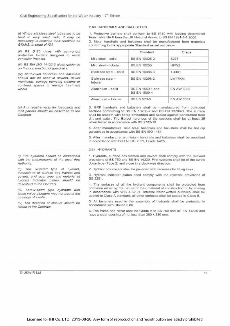
7/21/2019 The Civil Engineering Specification for the Water Industry 7th
http://slidepdf.com/reader/full/the-civil-engineering-specification-for-the-water-industry-7th 47/176Licensed to HHI Co. LTD. 2013-08-20. Any form of reproduction and redistribution are atrictly prohibited.
Civil Engineering Specification for
the
Water
Industry yth Ed
ition
i) Where stainless steel tubes are to be
bent to very small radii, it may be
necessary
to
describe their condition as
GKM S) instead
of KM.
ii)
as
6180 deals with permanent
protective barriers designed to resist
vehicular impacts.
iii)
as
N ISO 14122-3 gives guidance
on the construction
of
guardrails.
iv) Aluminium handrails and balusters
should
not
be used in sewers, sewer
manholes, sewage pumping stations or
confined spaces in sewage treatment
works.
v} Any requirements for toeboards and
inti// panels should be described in the
Contract.
i) Fire hydrants should be compatible
with the requirements of the local Fire
Authority.
ii) The required type of hydrant,
dimensions
of
surface box frames and
covers,
and
size, type and material
of
hydrant indicator plates should be
described in the Contract.
iii) Screw-down type hydrants with
loose valve plungers may not permit the
passage of swabs.
iv) The direction
of
closure should be
stated in the Contract.
UKWIR
l td
2.
60
HANDRAILS AND BALUSTERS
1
Protective barriers shall conform to
BS
6180 with loading determined
from Table NA.8 from the UK National Annex to BS EN 1991-1-1:2006.
2 Metal handrails
and
balusters shall
be
manufactured from materials
conforming to the appropriate Standard as set out below:
Standard Grade
Mi ld steel - solid BS EN 10025-2 S275
Mild steel - tubular BS
EN
10255 HFW2
Stainless steel solid
BS EN
10088-3 1.4401
Stainle
ss
steel - BS EN 10296-2 LW17KM
tubular
Aluminium - solid BS EN 1559-1 and EN AW 6082
BS EN
1559-4
Aluminium
tubular
BS EN 573-3 EN AW 6082
3
GRP handrails and
ba
lusters sha ll be manufactured from pultruded
sections conforming to BS EN 13706-2 and BS EN 13706-3. The surface
shall be smooth with fibres embedded and sea l
ed
against penetration from
dirt
and
water. The Barcol hardness
of
the sections shall
be
at least 35
when tested
in
accordance with
BS
2782-10.
4. After man ufacture, mild steel handrails
and ba
lusters shall
be
hot dip
ga
lvanised in accordance with BS EN ISO 1461.
5. After manufacture, aluminium handrails and
ba
lusters shall
be
anodised
in accordance with BS EN ISO 7599, Grade AA25.
2 61 HYDRANTS
1. Hydrants, surface box frames and covers sha ll comply with the relevant
provisions
of BS
750 and
BS EN
14339. Fire hydrants sha
ll be of
the screw
down type Type 2) and close in a clockwise direction.
2 Hydrant box covers shall
be
provided with recesses for lifting keys.
3. Hydrant indicator plates shall comply with the re levant provisions
of
BS
3251.
4. The surfaces
of
all the hydrant components sha ll be protected from
cor
ros ion either by the nature of their material of construction or by coating
in accordance with WIS 4-52-01. Internal water-wetted surfaces shall be
coated to Class A standard; all other surfaces shall
be
coated to Class B.
5. All fasteners used in the assembly
of
hydrants shall be protected in
accordance with Clause 2.86.
6. T
he
frame and cover shall
be
Grade A to
BS
750 and
BS EN
14339 and
have a clear opening of not less than 380 x 230 mm
41
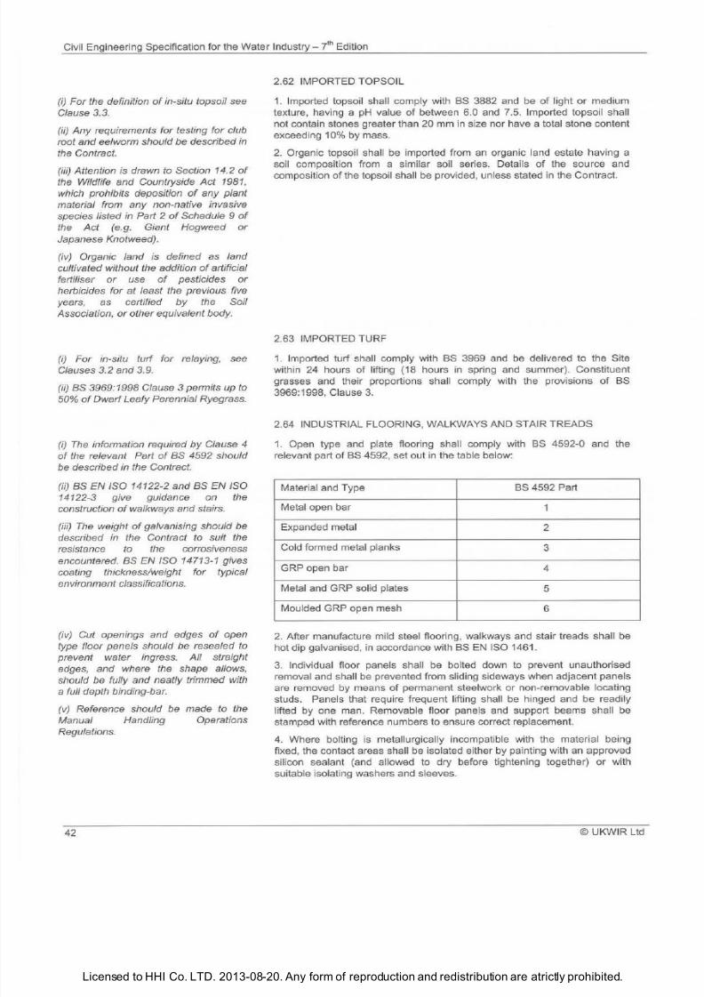
7/21/2019 The Civil Engineering Specification for the Water Industry 7th
http://slidepdf.com/reader/full/the-civil-engineering-specification-for-the-water-industry-7th 48/176Licensed to HHI Co. LTD. 2013-08-20. Any form of reproduction and redistribution are atrictly prohibited.
Civil Engineering Specification
for
the Water Industry 7th Edition
i)
For the definition
of
in-situ topsoil
see
Clause 3.3.
ii)
Any requirements for testing for club
root and eelworm should be described in
the Contract.
iii)
Attention s drawn to Section 14.2 of
the
Wildlife and Countryside
ct 1981
,
which prohibits deposition
of
any plant
material from any non-native invasive
species listed in Part 2
of
Schedule 9
of
the
Act e.g. Giant Hogweed or
Japanese Knotweed).
iv) Organic land is defined s land
cultivated without the addition of artificial
fertiliser
or
use
of
pesticides or
herbicides for at least the previous five
years, as certified by the Soil
Association,
or
other equivalent body.
i)
For in-situ turf for relaying,
see
Clauses
3.2 and 3.9.
ii) as 3969:1998 Clause 3 permits up to
50
of
Dwarf Leafy Perennial Ryegrass.
i) The
information required
by
Clause 4
of
the relevant Part
of
as 4592 should
be described in the Contract.
ii) aS
EN ISO 14122-2 and BS
EN
ISO
14122-3 give guidance on the
construction of walkways and stairs.
iii) The
weight of galvanising should be
described in the Contract to suit the
resistance to the corrosiveness
encountered. BS
EN
ISO 14713-1 gives
coating thickness/weight for typical
environment classifications.
iv) Cut openings and edges
of
open
type floor panels should be resealed
to
prevent water ingress. All straight
edges, and where the shape allows,
should be fully and neatly trimmed with
a full depth binding-bar.
v)
Reference should be made to the
Manual Handling Operations
Regulations.
42
2.62 IMPORTED TOPSOIL
1. Imported topsoi l shall comply with BS 3882 and be of light or medium
texture, having a pH value of between 6.0 and
7.5.
Imported topsoil sha ll
not contain stones greater than 20 mm in size nor have a total stone content
exceeding 10 by mass.
2 Organic topsoil shall be imported from an organic land estate having a
soil composition from a similar soil series. Details of the source and
composition
of
the topsoil sha ll be provided, unless stated in the Contract.
2.63 IMPORTED TURF
1. Imported turf shall comply with BS 3969 and be delivered
to
the Site
within 24 hours of lifting (18 hours in spring and summer). Constituent
grasses and
th
eir proportions sha ll comply with the provisions
of
BS
3969:1998, Clause 3.
2.64 INDUSTRIAL FLOORING,
WA
LKWAYS AND STAIR TREADS
1. Open type and plate flooring shall comply with BS 4592-0 and the
relevant part
of BS 4592, set out in the table below:
Material and Type
BS 4592 Part
Metal open bar
1
Expanded metal
2
Cold formed metal planks
3
GRP open bar
4
Metal and GRP solid plates
5
Moulded GRP open mesh
6
2. After manufacture mild steel flooring, walkways and stai r treads shall be
hot dip galvanised, in accordance with BS EN ISO 1461.
3.
Individual floor panels shall be bolted down to prevent unauthorised
removal and sha ll be prevented from sliding sideways when adjacent panels
are removed by means
of
permanent steelwork
or
non-removable locating
studs. Panels that require frequent lifting shall be hinged and be readily
lifted by one man. Removable floor panels and support beams shall be
stamped with reference numbers
to ensure correct replacement.
4. Where bolting is metallurgically incompatible with the material being
fixed, the contact areas shall be isolated either by pa inting with an approved
silicon sealant (and allowed to dry before tightening together) or
with
suitable isolating washers and sleeves.
© UKWIR Ltd
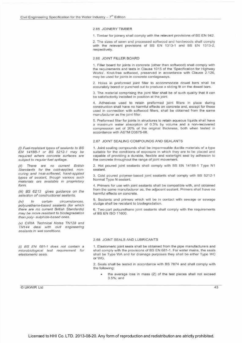
7/21/2019 The Civil Engineering Specification for the Water Industry 7th
http://slidepdf.com/reader/full/the-civil-engineering-specification-for-the-water-industry-7th 49/176Licensed to HHI Co. LTD. 2013-08-20. Any form of reproduction and redistribution are atrictly prohibited.
Civil Engineering Specification for the Water
Industry
7
t
Edition
i)
Fuel-resistant types of sealants to BS
N 14188-1 or as 5212-1 may be
required where concrete surfaces are
subject to regular fuel spillage.
ii) There are no current British
Standards for the cold-applied, non
curing
and
heat-softened, hand-applied
types
of
sealant, though various such
materials are available in proprietary
form.
iii) BS 6213 gives guidance on the
selection
o
constructional sealants.
iv)
In
certain circumstances,
polyurethane-based sealants for which
there are
no
current British Standards)
may be more resistant to biodegradation
than poly- sulphide-based ones.
v) CIRIA Technical Notes TN128 and
TN144
deal
with civil engineering
sealants in wet conditions.
ij as N
681-1
does not contain a
microbiological test requirement for
elastomeric
seals
2.65 JOINERY TIMBER
1
Timber for joinery shall comply with the relevant provisions
of
BS EN 942.
2
The sizes of sawn and processed softwood and hardwoods shall comply
with the relevant provisions
of BS EN
1313-1 and BS
EN
1313-2,
respectively.
2.66 JOINT FILLER BOARD
1 Filler board for joints in concrete (other than softwood) shal l comply with
the requirements and tests in Clause 1015 of the 'Specification for Highway
Works'. Knot-free softwood, preserved in accordance with Clause 2.126,
may be used for joints in concrete carriageways.
2 Holes in preformed joint filler to accommodate dowel
ba
rs shall
be
accurately bored or punched out to produce a sliding fit on the dowel bars.
3 The material comprising the joint filler shall
be
of such quality that it can
be satisfactorily installed in position at the joint.
4 Adhesives used to retain preformed joint fillers in place during
construction shall have no harmful effects on concrete and, except for those
used
in
connection with softwood
fil
lers, shall
be
obtained from the same
manufacturer as
the
join t filler.
5 Preformed
fil
ler for joints
in
structures to retain aqueous liquids shall have
a maximum water absorption of 0.3 by volume and a non-recovered
compression set of 20 of the original thickness, both when tested in
accordance with ASTM 03575-08.
2.67 JOINT SEALI
NG
COMPOUNDS AND SEALANTS
1.
Jo
int sealing compounds shall be impermeable ductile materials
of
a type
suitable for the conditions of exposure in which they are to
be
placed and
capable of providing a durable, flexible and watertight seal by adhesion to
the concrete throughout the range
of
oint movement.
2 Hot poured joint sealants shall comply with
BS EN
14188-1 Type
N1
sealant.
3
Cold poured polymer-based joint sealants shall comply with BS 5212-1
Normal Type N sealant.
4 Primers for use with joint sealants shall be compatible with , and obtained
from the same manufacturer as, the adjacent sealant. Primers shall have no
harmful effects on concrete.
5
Sealants and primers which will be in contact with sewage or sewage
sludge shall
be
resistant
to
biodeg radation.
6
Two-part polyurethane joint sea lants shall comply with the requirements
of BS EN ISO 11600.
2.68 JOINT SEALS AND LUBRICANTS
1
Elastomeric joint seals shall be obtained from the pipe manufacturers and
shall comply with the provisions of BS EN 681-1. For water mains, the seals
shall be Type WA and for drainage purposes they shall be either Type WC
orWG.
2
Seals sha
ll
be tested in accordance with BS 7874 and sha
ll
comply with
the following:
• the average loss in mass (Z) of the test pieces shall not exceed
3.5 ; and
©
UKWIR Ltd 43
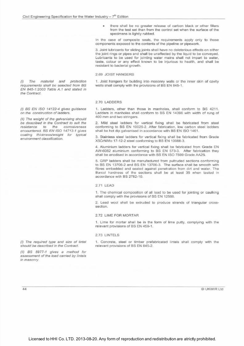
7/21/2019 The Civil Engineering Specification for the Water Industry 7th
http://slidepdf.com/reader/full/the-civil-engineering-specification-for-the-water-industry-7th 50/176Licensed to HHI Co. LTD. 2013-08-20. Any form of reproduction and redistribution are atrictly prohibited.
Civil Engineering Specification for the Water Industry 7lh Edition
i) The material and protection
requirements shall be selected from BS
EN 845-1:2003 Table A.1 and stated in
the Contract.
i)
BS N ISO 14122-4 gives guidance
on the construction of adders.
ii) The
weight of the galvanising should
be described in the Contract to suit
the
resistance to the corrosiveness
encountered. BS EN ISO 14713-1 gives
coating thickness/weight for typical
environment classification.
i)
The
reqwed
type and size of lintel
should be described in the Contract.
ii)
BS 5977-1 gives a method for
assessment of the load carried by lintels
in masonry.
44
• there shall be no greater release
of
carbon black
or
other fillers
from the test set than from the control set when the surface of the
specimens is lightly rubbed.
In the case of composite seals the requirements apply only to those
components exposed
to
the contents of the pipeline
or
pipework.
3. Joint lubricants for sliding joints shall have no deleterious effects on either
the joint rings
or
pipes and shall be unaffected by the liquid to be conveyed.
Lubricants to be used for jointing water mains shall not impart to water
taste colour
or
any effect known to be injurious to health and shall be
resistant to bacterial growth.
2.69 JOIST HANGERS
1. Joist hangers for building into masonry wal ls
or
the inner skin
of
cavity
walls sha
ll
comply with the provisions of BS EN 845-1.
2.70 LADDERS
1. Ladders other than those in manholes shall conform to BS 4211 .
Ladders in manholes shall conform to BS EN 14396 with width of rung of
400 mm and two stringers.
2 Mild steel ladders for vertical fixing shall be fabricated from steel
conforming to BS EN 10025-2 After fabrication low carbon steel ladders
shall be hot dip galvanised in accordance with BS EN ISO 1461.
3. Stainless steel ladders for vertical fixing shall be fabricated from Grade
X5CrNiMo 17-12-2 steel conforming to BS EN 10088-3.
4. Aluminium ladders for vertical fixing shall be fabricated from Grade EN
AW-6082 aluminium conforming to BS EN 573-3. After fabrication they
shall be anodised in accordance with BS EN ISO 7599 Grade AA25.
5
GRP ladders shall be manufactured from pultruded sections conforming
to BS EN 13706-2 and BS EN 13706-3. The surface shall be smooth with
fibres embedded and sealed against penetration from dirt and water. The
Barcol hardness
of
the sections shall be at least 35 when tested in
accordance with BS 2782-1 0.
2.71 LEAD
1
The chemical composition
of
all lead to be used for jointing
or
caulking
shall comply with the provisions
of
BS EN 12588.
2. Lead wool shall be extruded to produce strands
of
triangular cross
section.
2.72 LIME FOR MORTAR
1. Lime for mortar shall be in the form
of
lime putty complying with the
relevant provisions
of
BS EN 459-1 .
2.73 LINTELS
1. Concrete steel
or
timber prefabricated lintels shall comply with the
relevant provisions of BS EN 845-2.
©UKWIR Ltd
7/21/2019 The Civil Engineering Specification for the Water Industry 7th
http://slidepdf.com/reader/full/the-civil-engineering-specification-for-the-water-industry-7th 51/176Licensed to HHI Co. LTD. 2013-08-20. Any form of reproduction and redistribution are atrictly prohibited.
Civ
il
Engineering Specification for the Water
Industry
7
t
Edition
i)
The
shape and size of the opening
should be described in the Contract.
ii) The Contract should indicate any
requirements for locking devices.
iii) The responsibilities for supplying
manhole lifting keys should be detailed
in the Contract.
iv) BS
EN 124 is a minimum
performance standard only.
v) The maximum weight of components
of covers should be specified in the
Contract. The specifier should have
regard to
the
Manual Handling
Operations Regulations.
vi) Covers and frames should be
described
in
the
Contract.
vii) Covers and frames to manholes
containing air valves on water mains
should be ofa ventilated type.
viii)
The
information required
by
BS
9124:2008 Annex A should be stated in
the Contract.
i) For ll manholes, the size and
spacings
nd
type
of
manhole steps
should be described in
the
Contract.
ii) Unprotected aluminium steps should
not be used.
i) Consideration should be given to the
use of
a
marker tape and any
requirements described in the Contract.
ii) In the case of fire hydrants, the
requirements of the Fire Authority
should be established and included
in
the Contract.
iii) Appropriate marker tapes for other
buried services, such as fibre-optic
cables, should be described in the
Contract.
iv) Polyethylene mesh should only be
used as a tracing
system,
and placed
beneath
the
pipework to reduce the risk
of future damage to the mesh from
excavation.
v) Where other types of material for
marker posts are required, details
should be given in the Contract.
© UKWIR
Ltd
2.74 MANHOLE COVERS AND FRAMES
1 Manhole covers and frames shall comply with the re levant provisions of
BS EN 124, BS 7903 and the Highway Agency's 'Chamber Tops and Gully
Tops for Road Drainage and Services: Installation and Maintenance'
HA 104/09.
2. A
ll
manhole covers shall have closed keyways.
3.
Chamber access covers with a clear opening exceeding 1 m shall
conform
to
BS 9124.
2.75 MANHOLE STEPS
1. Steps for manholes and other chambers shall be Type D C lass 1
complying with the requirements of BS EN 13101.
2.76 MARKER TAPE AND MARKER POSTS
1.
Marker tape for buried water mains shall be blue
PVC
or polyethylene
ribbon at least 150 mm wide incorporating a corrosion-resistant tracing
system and sha ll be printed with the words WATE R MAIN in bold capital
letters throughout its length and at intervals not exceeding 700
mm.
2. Marker tape for buried cables shall be yellow PVC or polyethylene ribbon
at least 150 mm wide and
sha
ll be printed with the words ELECTRIC
CABLE in bold capital letters throughout its length
and
at intervals not
exceeding 700 mm.
3.
Marker tape for buried wastewater pipes or pumpi
ng
mains
sha
ll
be
red
PVC or heavy gauge polyethylene sheeting at least 150 mm wide and shall
be printed with the words GRAVITY SEWER or PRESSURE SEWER
in
bold capital letters throughout its length and at intervals not exceeding
700
mm
and shall incorporate a corrosion-resistant tracing system for non
meta llic pipes.
4.
Valve or pipeline marker posts shall be precast reinforced concrete
1120 mm high. The tops of marker posts shall be fixed so that their finished
level is 500-600 mm above the final surface.
5. Marker posts shall be fitted with a 180 x 205 mm indicator plate to
indicate WO SV, AV or FH as appropriate, together with main size
and
distance from post. Plates shall comply with BS
3251
and shall
be
fixed to
the post with stainless steel fixings.
6. The colour for fire hydrant plates shall be in accordance with BS 3251
(black letters on a yellow background).
45
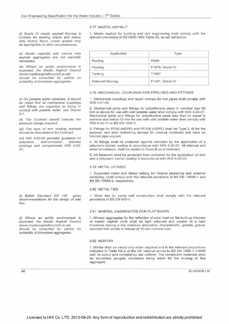
7/21/2019 The Civil Engineering Specification for the Water Industry 7th
http://slidepdf.com/reader/full/the-civil-engineering-specification-for-the-water-industry-7th 52/176Licensed to HHI Co. LTD. 2013-08-20. Any form of reproduction and redistribution are atrictly prohibited.
Civil Engineering Specification for the Water
Industry 7th
Edition
i) Grade IV mastic asphalt flooring is
suitable for loading sheds and heavy
duty factory floors. Lower grades may
be appropriate in other circumstances.
ii) Mastic asphalts with natural rock
asphalt aggregates are not normally
necessary.
iii) Where an acidic environment is
expected, the Mastic Asphalt Council
www.masticasphaltcouncil.co.
uk)
should be consulted for advice on
suitability
o
imestone aggregates.
i) On
potable water pipelines,
it
should
be noted that all mechanical couplings
and fittings are regarded as being in
contact with potable water, see Clause
2.1.
ii) The Contract should indicate the
pressure ratings required.
iii) The type
o
end loading restraint
should be described in the Contract.
iv) /GN 4-52-02 provides guidance on
polymeric anti-corrosion barrier)
coatings and complements WIS 4-52-
01.
i)
British Standard DO 140 gives
recommendations for the design
o
wall
ties.
i)
Where an acidic environment is
expected, the Mastic Asphalt Council
www.masticasphaltcouncil.
co.
uk)
should be consulted for advice on
suitability o imestone aggregates.
46
2.77 MASTIC ASPHALT
1. Mastic asphalt for building and civil engineering shall comply with the
relevant provisions
of
BS 6925:1988 Table 25, as set out below:
Application Type
Roofing R988
Flooring F1 076, Grade IV
Tanking T1097
Coloured floori
ng
F1451 , Grade IV
2.78 MECHANICAL COUPLINGS FOR PIPELINES AND FITTINGS
1. Mechanical couplings and repair clamps for iron pipes shall comply with
WIS 4-21-02.
2.
Mechanical joints and fittings for polyethylene pipes in nominal size 90
mm or above for use with cold potable water shall comply with WIS 4-24-01.
Mechanical joints and fittings for polyethylene pipes less than or equal to
nominal size below 63 mm for use with cold potable water shall comply with
WIS 4-32-11
orBS
EN
1254-3.
3. Fittings for PE80 MOPE) and PE1 00 HOPE) sha ll be Type 2, fit for the
purpose, end load restraining except for unusual locations) and have an
internal pipe support.
4. All fittings shall be protected against corrosion
by
the application
of
a
polymeric barrier coating in accordance with WIS 4-52-01. All internal and
external surfaces sha
ll
be coated to Class 8 as a min imum.
5. All fasteners shall be protected from corrosion by the application of zinc
and a polymeric barrier coating
in
accordance with WIS 4-52-03.
2.79 METAL LATHING
1. Expanded metal and ribbed lathing for internal plastering and external
rendering, shall comply with the relevant provisions
of
BS
EN
13658-1 and
BS EN 13658-2 respectively.
2.80 METAL TIES
1.
Metal ties for cavity wall construction
sha
ll comply with
the
relevant
provisions
of
BS EN 845-1.
2.81
MINERAL AGGREGATES FOR FLAT ROOFS
1. Mineral aggregates for the reflecti
on
of
solar heat on flat built-up bitumen
or mastic asphalt roofs shall
be
light coloured and consist
of
a hard
limestone havi
ng
a low moisture absorption characteristic, granite, gravel,
calcined flint, calcite or felspar of 10 mm nom inal size.
2.82 MORTAR
1.
Mortar sha
ll
be mixed only when required and
in
the relevant proportions
indicated in Table NA.2
of
the UK national annex to BS EN 1996-1-1:2005
until its colour and consistency are un iform. The constituent materials shall
be accurately gauged, allowance being made for the bulking
of
fi
ne
aggregate.
UKWIR Ltd
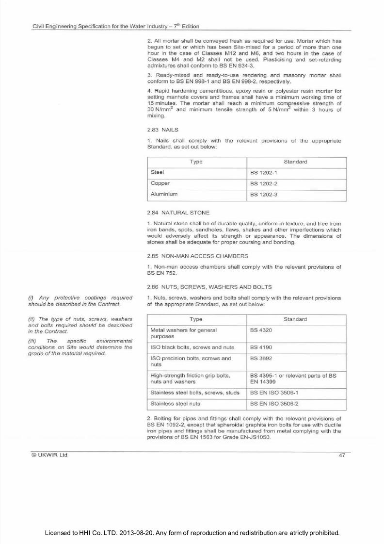
7/21/2019 The Civil Engineering Specification for the Water Industry 7th
http://slidepdf.com/reader/full/the-civil-engineering-specification-for-the-water-industry-7th 53/176Licensed to HHI Co. LTD. 2013-08-20. Any form of reproduction and redistribution are atrictly prohibited.
Civil Engineering Specification for the Water Industry -
i hEd
ition
i) ny protective coatings required
should be described
in
the Contract.
ii) The type of nuts, screws washers
and
bolts required should be described
in the Contract.
iii) The specific environmental
conditions on Site would determine the
grade
of he
material required.
©
UKWIR Ltd
2. A
ll
mortar shall
be
conveyed fresh as required for use. Mortar which has
beg un to set or which has been Site-mi
xed
for a period
o
more than one
hour in the case of Classes M12 and M6 and two hours in the case
o
Classes
M4
and
M2
shall not
be
used. Plasticising and set-retarding
admixtures
sha ll
conform to
BS EN
934-3.
3. Ready-mixed
and
ready-to-use rendering
and
masonry mortar sha
ll
conform to BS EN 998-1 and BS
EN
998-2 respectively.
4. Rapid hardening cementitious epoxy resin or polyester resin mortar for
setting manhole covers and frames shall have a minimum working
ti
me
o
15 minutes. The mortar sha ll reach a min imum compressive strength
o
30
N/mm
and minimum tensile strength o 5 N/mm
within 3 hours of
mixing.
2.83 NAILS
1. Nails sha ll comply with the relevant provisions
o
the appropriate
Standard as
set out below:
Type
Standard
Steel
BS
1202-1
Copper
BS
1202-2
Aluminium
BS 1202-3
2.84 NATURAL STONE
1. Natural stone sha ll be
o
durable quality uniform in texture and free from
iron bands spots sa ndholes flaws shakes and other imperfections wh ich
would adversely affect its strength or appearance. T
he
dimensions
o
stones shall
be
adequate for proper coursing and bonding.
2.85 NON -MAN ACCESS CHAMBERS
1. Non-man access chambers shall comply with the re levant provisions of
BS EN 752.
2.86 NUTS SCREWS WASHERS AND BOLTS
1. Nuts screws washers and bol
ts
shall comply with the relevant provisions
of the
appropriate
Standard as set out below:
Type
Standard
Metal washers for general BS4320
purposes
ISO black bolts screws and nuts
BS
4190
ISO precision bolts screws
and BS
3692
nuts
High -strength fric
ti
on grip bolts
BS
4395-1 or relevant parts
o BS
nuts and washers
EN
14399
Stainless steel bolts screws studs
BS
EN ISO 3506-1
Stainless steel nuts BS EN ISO 3506-2
2.
Bolting for pipes and fittings shall comply with the relevant provis ions
o
BS EN
1092 2 except that spheroi
da
l graphite iron bolts for use with ductile
iron pipes and fittings shall
be ma
nufactured from metal complying with
the
provisions
o
BS EN
1563 for Grade EN-JS1050.
47
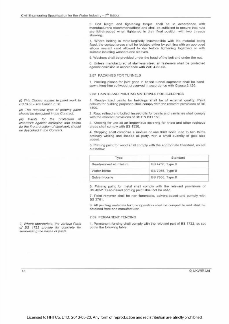
7/21/2019 The Civil Engineering Specification for the Water Industry 7th
http://slidepdf.com/reader/full/the-civil-engineering-specification-for-the-water-industry-7th 54/176Licensed to HHI Co. LTD. 2013-08-20. Any form of reproduction and redistribution are atrictly prohibited.
Civil Engineering Specification for the Water Industry J h Edition
i)
This Clause applies
to
paint work to
BS
6150
see Clause 6.26.
ii)
The
required type
of
priming paint
should be described in the Contract.
iii) Paints for
the
protection
of
steelwork against corrosion and paints
for the fire protection of steelwork should
be described in the Contract.
i)
Where appropriate, the various Parts
of BS 1722 provide for concrete for
surrounding the bases
of
posts.
48
3
Bolt length and tightening torque shall be in accordance with
manufacturer s recommendations and shall be sufficient to ensure that nuts
are full-threaded when tightened in their final position with two threads
showing.
4 Where bolting is metallurgical ly incompatible with the material being
fixed, the contact areas shall be isolated either by painting with an approved
silicon sealant (and al lowed to dry before tightening together) or with
suitable isolating washers and sleeves.
5 Washers shall be provided under the head of the bolt and under the nut.
6 Unless manufactured of stainless steel, all fasteners shall be protected
against corrosion in accordance with WIS 4-52-03.
2 87
PACKINGS FOR TUNNELS
1
Packing pieces for joint gaps in bolted tunnel segments shall
be
band
sawn, knot-free softwood, preserved in accordance with Clause 2.126.
2.88 PAINTS AND PAINTING MATERIALS FOR BUILDINGS
1 Ready-mixed paints for bu
il
dings shall be
of
external quality. Paint
colours for building purposes shall comply with the relevant provisions of BS
4800.
2
Raw, refined and boiled linseed oi ls for paints and varnishes sha ll comply
with the relevant provisions of BS EN ISO 150.
3 Knotting for use as an impervious covering for knots and other resinous
areas shall comply with BS
1336
4 Stopping shall comprise a mixture of one third white lead to two thirds
ordinary whiting and linseed o
il
putty, with a small quantity of gold size
added.
5
Priming paint for wood shall comply with the appropriate Standard, as set
out below:
Type Standard
Ready-mixed aluminium BS 4756, Type II
Water-borne BS 7956, Type B
Solvent-borne
BS 7956, Type B
6
Priming paint for metal shall comply with the relevant provisions
of
BS 4652. Lead-based priming paint shall not be used .
7
Paint remover shall be non-flammable, solvent-based and comply with
BS 3761 .
8. All painting materials for one operation shall be compatible an d shall be
obtained from one manufacturer.
2.89 PERMANENT FENCING
1. Permanent fencing shall comply with the relevant part of BS 1722, as set
out in the following table:
© UKWIR Ltd
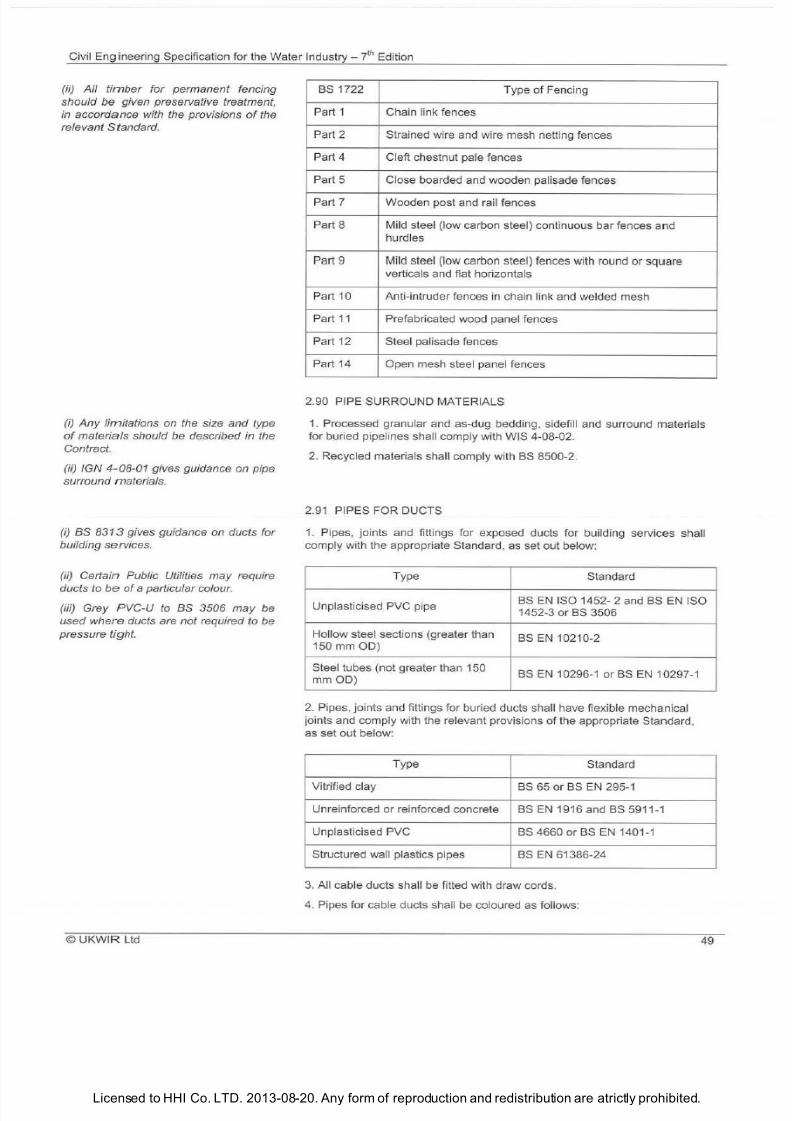
7/21/2019 The Civil Engineering Specification for the Water Industry 7th
http://slidepdf.com/reader/full/the-civil-engineering-specification-for-the-water-industry-7th 55/176Licensed to HHI Co. LTD. 2013-08-20. Any form of reproduction and redistribution are atrictly prohibited.
Civil Engineering Specification for the Water Industry- ? h Edition
ii) All t imber for permanent fencing
should be given preservative treatment,
in accordance with the provisions of the
relevant Standard.
i) Any
limitations on the size and type
of materials should be described in the
Contract.
ii) IGN 4-08-01 gives guidance on pipe
surround materials.
i)
BS
83 3
gives guidance on ducts for
building services.
ii) Certain Public Utilities may require
ducts to be
of
a particular colour.
iii) Grey PVC-U to BS 3506 may be
used where ducts are not required to be
pressure tight.
© UKWIR Ltd
BS
1722
Type of Fencing
Part 1
Chain link fences
Part 2
Strained wire and wire mesh netting fences
Part
4
Cleft chestnut pale fences
Part 5
Close boarded and wooden palisade fences
Part 7
Wooden post and rail fences
Part
8
Mild steel low carbon steel) continuous bar fences and
hurdles
Part 9
M
il
d steel low carbon steel) fences with round or square
verticals and flat horizontals
Part 10
Anti-intruder fences in chain link and welded mesh
Part
11
Prefabricated wood panel fences
Part
12
Steel palisade fences
Part 14 Open mesh steel panel fences
2.90
PIPE SURROUND MATERIALS
1. Processed granular and as-dug bedding, sidefill and surround materials
for buried pipelines shall comply with WIS 4 08 02 .
2. Recycled materials shall comply with BS 8500 2.
2.91 PIPES FOR DUCTS
1. Pipes, joints and fittings for exposed ducts for building services shall
comply with the appropriate Standard , as set out below:
Type
Standard
Unplasticised PVC pipe
BS EN ISO 1452 2 and BS EN ISO
1452 3 orBS 3506
Ho
ll
ow steel sections greater than
150
mm 00
BS EN 10210 2
Steel tubes not g realer than 150
BS EN
10296 1 orBS
EN
1•0297 1
mmOD
2 Pipes, joints and fittings for buried ducts shall have flexible mechanical
joints and comply with the re levant provisions
of
the appropriate Standard ,
as set out below:
Type
Standard
Vitrified clay BS
65
or BS EN
295 1
Unreinforced or reinforced concrete BS EN
1916
and BS
5911 1
Unplasticised PVC
BS 4660 orBS EN 1401 1
Structured wall plastics pipes BS EN
61386 24
3. All cable ducts sha ll be fitted with draw cords.
4. Pipes for cable ducts shall be coloured as follows:
49
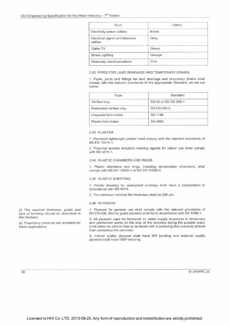
7/21/2019 The Civil Engineering Specification for the Water Industry 7th
http://slidepdf.com/reader/full/the-civil-engineering-specification-for-the-water-industry-7th 56/176Licensed to HHI Co. LTD. 2013-08-20. Any form of reproduction and redistribution are atrictly prohibited.
Civil Engineering Specification for the Water Industry 7t
Ed
ition
i) The
required thickness, grade and
type
o
bonding should be described in
the Contract.
ii) Proprietary products are available for
these applications.
50
Duct Colour
Electricity power cables
Black
Electrical signal and telecoms Grey
cables
Cable TV
Green
Street Lighting Orange
Motorway communications
Pink
2.92 PIPES
FO
R LAND DRAINAGE AND TEMPORARY DRAINS
1.
Pipes joints and fittings for land drainage and temporary drains shall
comply with t
he
relevant provisions of the appropriate Standard as set out
below:
T
ype
Standard
Vitrified clay
BS
65
or BS
EN 295 1
Perforated vitrified clay
BS
EN
295 5
Clayware field drains BS 1196
Plastic field drains BS 4962
2.93 PLAST
ER
1. Premixed lightweight plaster shall comply with the relevant provisions
of
BS EN 13279 1.
2. Polyvinyl acetate emulsi
on
bonding agents for indoor use shall comply
with BS 5270 1
2.94 PLASTIC CHAMBERS AND RINGS
1 Plastic chambers and rings including demarcation chambers sha ll
comply with
BS EN
13598 1 or
BS EN
13598 2.
2.95 PLASTIC SHEETING
1.
Plastic sheeting for waterproof underlay sha
ll
have a composition in
accordance with
BS
6076.
2. The minimum nominal fi lm thickness shall
be
250 IJm
2.96 PLYWOOD
1. Plywood for general use shall comply with the relevant provisions of
BS EN
636. Marine grade plywood shall be in accordance with
BS
1088 1.
2. A ll plywood used for formwork on water supply structures in temporary
and permanent works on the si
de
of the concrete facing the potable water
shall either be phenol free or be faced with a surfacing that prevents phenol
from contacting the concrete.
3. Interior quality plywood sha ll have
MR
bonding and external quality
plywood sha ll have WBP bonding.
© UKWIR Ltd
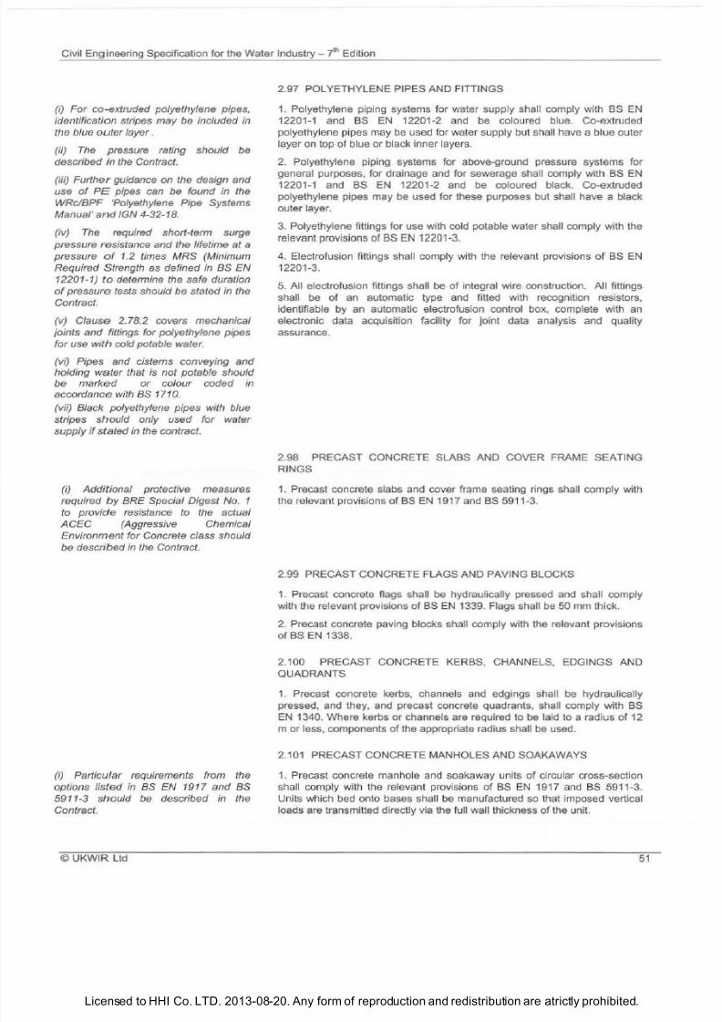
7/21/2019 The Civil Engineering Specification for the Water Industry 7th
http://slidepdf.com/reader/full/the-civil-engineering-specification-for-the-water-industry-7th 57/176Licensed to HHI Co. LTD. 2013-08-20. Any form of reproduction and redistribution are atrictly prohibited.
Civil Engineering Specification for the Water Industry 7
t
Edition
i) For co-extruded polyethylene pipes,
identification stripes may be included in
the blue outer ayer .
(ii)
The
pressure rating should be
described in the Contract.
(iii) Further guidance on the design and
use of PE pipes can be found in the
WRc BPF 'Polyethylene Pi
pe
Systems
Manual
and
IGN 4-32-18.
iv) The required short-term surge
pressure resistance and the lifetime at a
pressure of 1.2 times MRS (Minimum
Required Strength as defined in BS EN
12201-1) to determine the safe duration
of
pressure tests should be stated in the
Contract.
(
v)
Clause 2.78.2 covers mechanical
;oints and fittings for polyethylene pipes
for use with cold potable water.
vi) Pipes and cisterns conveying and
holding water that is not potable should
be marked or colour coded in
accordance
with
as
1710.
(vii) Black polyethylene pipes with blue
stripes should only used for water
supply
if
stated in the contract.
i) Additional protective measures
required by BRE Special Digest No. 1
to provide resistance to the actual
ACEC (Aggressive Chemical
Environment for Concrete class should
be described
in the Contract.
i) Particular requirements from the
options listed in BS EN 1917 and BS
5911-3 should be described in the
Contract.
© UKWIR Ltd
2.97 POLYETHYLENE PIPES AND FITIINGS
1 Polyethylene piping systems for water supply shall comply with BS EN
12201-1 and BS EN 12201-2
and
be coloured blue. Co-extruded
polyethylene pipes may be used for water supply but sha ll have a blue outer
layer on top of blue or black inner layers.
2 Polyethylene piping systems for above-ground pressure systems for
general purposes for drainage and for sewerage shall comply with BS EN
12201-1 and BS EN 12201 -2 and be coloured black. Co-extruded
polyethylene pipes may be used for these purposes but
sha
ll have a black
outer layer.
3.
Polyethylene fittings for use with cold potable water shall comply with the
relevant provisions of BS EN 12201 3.
4. Electrofusion fittings sha ll comply with the relevant provisions of BS EN
12201
-3
5.
All electrofusion fittings shall be of integral wire construction. All fittings
shall be of an automatic type
and
fitted with recognition resistors
identifiable by an automatic electrofusion control box complete with an
electronic data acquisition facility for joint data analysis and quality
assurance.
2.98 PRECAST CONCRETE SLABS AND COVER FRAME SEATING
RINGS
1.
Precast concrete slabs and cover frame seating rings shall comply with
the relevant provisions of BS EN 1917 and BS 5911-3.
2.99 PRECAST CONCRETE FLAGS AND PAVING BLOCKS
1. Precast concrete flags shall be hydraulically pressed and shall comply
with the relevant provisions
of BS EN
1339. Flags shall be 50 mm thick.
2. Precast concrete paving blocks shall comply with the relevant provisions
of BS
EN
1338.
2.100 PRECAST CONCRETE KERBS CHANNELS EDGINGS AND
QUADRANTS
1. Precast concrete kerbs channels and edgings shall be hydraulically
pressed and they and precast concrete quadrants sha
ll
comply with BS
EN
1340. Where kerbs or channels are requi
red
to be
la
id to a
rad
i
us of
12
m or less components of the appropriate rad ius shall be used.
2 101 PRECAST CONCRETE MANHOLES AND SOAKAWAYS
1.
Precast concrete manhole and soakaway units of circular cross-section
shall comply with the relevant provisions of BS
EN
1917
and BS
5911-3.
Units which
bed
onto bases shall
be
manufactured so that imposed vertical
loads are transmitted directly via the full wall thickness of the unit.
51
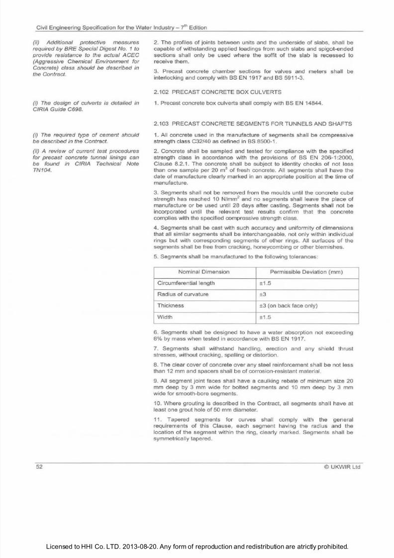
7/21/2019 The Civil Engineering Specification for the Water Industry 7th
http://slidepdf.com/reader/full/the-civil-engineering-specification-for-the-water-industry-7th 58/176Licensed to HHI Co. LTD. 2013-08-20. Any form of reproduction and redistribution are atrictly prohibited.
Civil Engineering Specification for the Water
Industry
i h
Edition
ii) Additional protective measures
required by BRE Special Digest No. 1 to
provide resistance to the actual ACEC
Aggressive Chemical Environment for
Concrete) class should be described in
the Contract.
i) The design of culverts is detailed in
CIRIA Guide C698.
i) The required type
of
cement should
be described
n
the Contract.
ii) A review
of
current test procedures
for precast concrete tunnel linings can
be found in CIRIA Technical Note
TN104.
52
2 The profiles
of
joints between units and the underside
of
slabs, shall be
capable
of
withstanding applied loadings from such slabs and spigot-ended
sections shall only be used where the soffit
of
the slab is recessed to
receive them.
3 Precast concrete chamber sections for valves
and
meters shall be
interlocking and comply with BS EN 1917 and BS 59 11-3.
2.102 PRECAST CONCRETE BOX CULVERTS
1 Precast concrete box culverts shall comply with BS EN 14844.
2.103 PRECAST CONCRETE SEGMENTS FOR TUNNELS AND SHAFTS
1
All concrete used in the manufacture
of
segments shall
be
compressive
strength class C32/40 as defined in BS 8500-1.
2 Concrete shall be sampled and tested for compliance with the specified
strength class
in
accordance with the provisions
of BS EN
206-1 :2000,
Clause 8.
2 1
. The concrete shall
be
subject to identity checks
of
not less
than one sample per 20 m
of
fresh concrete. All segments shall have the
date
of
manufacture clearly marked in an appropriate position
at
the time of
manufacture.
3
Segments shall not be removed from the moulds until the concrete cube
strength has reached 10 N/mm
2
and
no
segments shall leave the place
of
manufacture or
be
used until 28 days after casting. Segments shall not be
incorporated until the relevant test results confirm that the concrete
complies with the specified compressive strength class.
4. Segments shall
be
cast with such accuracy and uniformity of dimensions
that all similar segments shall be interchangeable, not only within individual
rings but with corresponding segments
of
other rings. All surfaces
of
the
segments shall be free from cracking, honeycombing or other blemishes.
5
Segments shall be manufactured to the following tolerances:
Nominal Dimension Permissible Deviation (mm)
Circumferential length
±1.5
Radius
of
curvature
±3
Thickness ±3 (on back face only)
Width ±1 .5
6. Segments shall be designed to have a water absorption not exceeding
6 by mass when tested in accordance with BS EN 1917.
7
Segments shall withstand handling, erection and any shield thrust
stresses, without cracking, spalling or distortion.
8 The clear cover
of
concrete over any steel reinforcement shall
be
not less
than 12 mm and spacers shall be of corrosion-resistant material.
9. All segment joint faces shall have a caulking rebate
of
minimum size 20
mm deep by 3 mm wide for bolted segments and 10 mm deep by 3 mm
wide for smooth-bore segments.
10. Where grouting is described in the Contract, all segments shall have at
least one grout hole
of
50 mm diameter.
11 . Tapered segments for curves shall comply with the general
requirements
of
this Clause, each segment having the radius and the
location of the segment within the ring, clearly marked. Segments shall be
symmetrically tapered.
©
UKWIR Ltd
7/21/2019 The Civil Engineering Specification for the Water Industry 7th
http://slidepdf.com/reader/full/the-civil-engineering-specification-for-the-water-industry-7th 59/176Licensed to HHI Co. LTD. 2013-08-20. Any form of reproduction and redistribution are atrictly prohibited.
Civil Engineering Specification for the Water Industry 7th Edition
i)
BS EN
1992-3 covers the design
and
construction of structures used for
retaining aqueous liquids. Its scope
includes precast concrete.
ii) The type
of seal WA, WB , we
,
wo
,
etc.) should be described in the
Contract.
iii) The required exposure class of
concrete should be stated in the
Contract.
i) Particular requirements from the
options listed in
BS
EN 639,
BS
EN 642
orBS
5911 5
should be described
in
the
Contract.
ii) The Contract should describe
whether
cylinder or non-cylinder type
pipes and fittings are required.
i) Details of profiled steel sheeting
should be described in the Contract.
UKWIR Ltd
2.104 PRECAST CONCRETE SETTING BLOCKS FOR PIPES
1.
Precast setti
ng
blocks for pipes shall have rectangular faces, with
sufficient plan area to prevent punching
of
the
bl
inding concrete or final
surface, and to provide an adequate seating for the
p1pes.
They shall be
manufactured from compressive strength C16/20 concrete using the same
type
of
cement as in the adjacent concrete bed. Blocks shall not be used
until they have achieved a cube strength of 13.5 N/mm
2
•
2.105 PRECAST CONCRETE TANKS
1. The design and construction of concrete panels for pre-cast concrete
tanks shall comply with BS
EN
1992-3.
2.
Rubber
and
thermoplastics seals between panels floor slabs , etc., shall
comply with
BS
EN 681-1 and
BS
EN 681-2, respectively.
3. Class C32/40 concrete shall
be
used as a m
in
imum for
the
concrete
panels.
2.106 PRESTRESSED CONCRETE PIPES AND FITTINGS
1. Prestressed concrete pressure pipes and fittings shall comply with the
relevant provisions of BS EN 639, and BS EN 642. Prestressed concrete
pipes and fittings for drainage and sewerage purposes sha ll comply wi
th
the
relevant provisions of BS 5911 -5.
2.
Unless steam cured, no pipes or fittings shall leave the place
of
manufacture until they have been allowed to cure and mature under suitable
conditions for a total period
of
not less than 28 days.
2.107 PRESTRESSED PRECAST CONCRETE FLOORS
1.
Precast prestressed concrete floors
sha ll be
formed from units
manufactured to BS
EN
13369.
2.108 PROFILED STEEL SHEETI
NG
1. Profiled steel sheeting and cladding shall comply with
BS EN
14782.
2.109 PROPYLENE CO-POLYMER PRESSURE PIPES
1. Propylene co-polymer pressure pipe shall comply with the relevant
provisions
of
BS
4991
and, where it is to be in contact with potable water,
shall
be
Series
1.
2.
110 PTFE TAPE
1.
Unsintered polytetrafluoroethylene PTFE) tape for thread sealing
applications shall comply with BS 7786.
2.111 PULVERISED-FUEL ASH
1. Pu lverised-fuel ash PFA) and fly ash, for use as a component material in
cementitious grout or non-structural concrete, shall comply with BS 3892-2
and
BS
3892-3.
2.
PFA for use as a cementitio
us
component
In
structural concrete and
annulus grouts sha ll comply with
BS EN
450-1 fineness category S, loss on
ignition category A or B PFA for annulus grouts shall be pre-blended and
bagged before delivery to
the
Site.
53
7/21/2019 The Civil Engineering Specification for the Water Industry 7th
http://slidepdf.com/reader/full/the-civil-engineering-specification-for-the-water-industry-7th 60/176Licensed to HHI Co. LTD. 2013-08-20. Any form of reproduction and redistribution are atrictly prohibited.
Civil Engineering Specification for the Water
Industry i
Edition
i) The Contract should describe the
section required for aluminium
and
PVC
U gutters.
ii) The Contract should describe the
required grade
and
shape
of
sheet and
strip aluminium pipes and gutters.
iii)
S
EN 877 deals with flexible joints
for cast iron drainpipes and fittings.
iv) The Contract should describe
whether ears are required on cast iron
pipes
and
fittings.
v) The Contract should describe the
required colour
of
PVC-U pipes
and
fittings.
i) The required type, grade, category,
classification, size, group or colour
of
roof covering material should be
described in the Contract.
54
3.
Conditioned PFA or fly ash for use as a fill material shall
be
supplied dry
and shall be compacted to ± 2
of
the optimum moisture content and
maximum dry density in the ranges 18-25 and 1200-1500 kg/m
3
respectively, when determined in accordance with BS 1377-4 (light or heavy
Hammer Method rather than Rammer Method . The PFA fill shall not be
reused when producing the compaction curve .
2.112 RAINWATER PIPES AND
GUTIERS
1.
Rainwater pipes, gutters, fixings and accessories shall comply with the
relevant provisions
of
the appropriate Standard , as set out below:
Material Standard
Cast iron
BS460
Aluminium BS EN 612
Steel
BS EN 612
PVC-U (gutters) BS
EN
607
PVC-U (downpipes) BS
EN
12200-1
Brackets for gutters to
BS EN
607 BS
EN
1462
and BS
EN
612
2.113 ROLLED ASPHALT
1. Hot rolled asphalt shall comply with the relevant provisions
of
BS EN
13108-4.
2.114 ROOF COVERINGS
1.
Roof coverings sha
ll
comply with the relevant provisions
of
the
appropriate Standard, as set out in the following Table :
Material/Type
Standard
Clay tiles and fittings BS EN 1304
Concrete tiles and fittings BS EN 490
Slates BS
EN
12326-1
Felt
BS
EN
13707
2.115 SAFETY CHAINS IN SEWERS
1. Mild steel safety chain shall be medium tolerance chain conforming to BS
EN
818-3 Grade 4 nominal size 8 x 24. After manufacture, mild steel safety
chains shall be hot dip galvanised in accordance with
BS EN
ISO 1461.
2.
Stainless steel safety chain shall be manufactured from Grade X5CrNiMo
17-12-2 steel conforming to BS EN 10088-3. Chain links shall be welded
and have
an
internal length not exceeding 45 mm and an internal width of
between
12
mm and 18 mm. The fins caused
by
welding shall be removed
and the weld sha ll be smoothly finished all round.
3. The chain shall have a breaking force
of
30
kN
and a proof force
of
15
kN
when tested in accordance with BS EN 818-1.
4. Anchor bolts for fixing safety chains shall be of the stainless steel safety
type which provides a progressive mode of failure.
©UKWIR Ltd
7/21/2019 The Civil Engineering Specification for the Water Industry 7th
http://slidepdf.com/reader/full/the-civil-engineering-specification-for-the-water-industry-7th 61/176Licensed to HHI Co. LTD. 2013-08-20. Any form of reproduction and redistribution are atrictly prohibited.
Civil Engineering Specification for the Water
Industry yl
Edition
i)
Taps
should be specifically designed
for sampling such as chrome-plated
gunmetal
with
tapered spout and
protective cover, commonly referred to
as the Harris Tap
.
(ii) Single non-rising spindle headworks
tap to S EN 200 with the flow
straightener or aerator removed may
suitable for this purpose.
i)
The requirement for
sands
to be
washed
s
additional to the requirements
of the Standards but
s in
line with the
main conclusion
of
CIRIA Report R59
'Building Sands: Availability, Usage and
Compliance with Specification
Requirements'.
i)
Appendix A
of
each WIS .
lists
information to be established for
particular design situations.
i)
BS EN 877 deals
with
flexible joints
for cast iron soil, waste and ventilating
pipes and fittings.
© UKWIR l td
2.116 SAMPLETAPS
1.
Sample taps shall be metal complying with
BS EN
200 or equivalent,
without attac
hm
ents or inserts.
2. For sample points located externally, the tap shall
be
enclosed in a
lockable, purpose-designed sample pillar.
3.
Taps for sampling purposes shall be a % male chrome sample tap, %
BSP inlet. They sha ll be permanently labelled with Sample Name/Water
Quality Site No./Required Flushing Time .
2.117 SANDS
1.
Sands for mortar and grout shall comply with BS
EN
13139 and
PD
6682-3.
2. Sands for floor screeds shall comply with the relevant provisions of
BS EN 12620 and
PD
6682-1.
3. Sands for external rendering and internal plastering with lime and
Portland cement shall comply with the relevant provisions of BS EN 13139
and PD 6682-3.
4. All sands required to comply with BS EN 12620 and PD 6682-1, BS EN
13139 and
PD
6682-3 shall be washed sands.
2.118 SEWER LIN INGS
1.
Sewer linings shall comply with the relevant provisions
of
the appropria te
Standard, as set out
in
the following Table:
Type
WIS
Glassfibre reinforced cement (GRC) 4-12-04
Precast gunite
4-12-05
Precast and in-situ ferrocement 4-12-06
Polyethylene (PE) pipes (non-pressure
4-32-05
applications)
Glassfibre reinforced plastics (G
RP
)
4-34-02
Cured-in-place pi
pe
(CIPP)
4-34-04
Polyester resin concrete (PRC)
4-34-05
2.119 SOIL, WASTE AND VENTILATING PIPES
1.
Soil, waste and ventilating pipes, fittings and accessories for above
ground dra inage systems shall comply with the relevant provisions of the
appropriate Standard, as set out below:
Mate rial
Standard
Cast iron
BS 416-1
orBS
EN 877
PVC-U (soil and ventilating)
BS 4514
Polypropylene (waste) BS EN 14
51
-1
Plastics (waste)
BS EN 1329-1 , BS EN 1455-1, BS EN
151
9-1, BS EN 1565-1 and
BS EN
1566-1
55
7/21/2019 The Civil Engineering Specification for the Water Industry 7th
http://slidepdf.com/reader/full/the-civil-engineering-specification-for-the-water-industry-7th 62/176Licensed to HHI Co. LTD. 2013-08-20. Any form of reproduction and redistribution are atrictly prohibited.
Civil Engineering Specification for the Water
Industry i
Edition
i)
The required grade
o
steel should be
described in the Contract.
ii)
The requirement for piles to be
coated should be deleted
i
no part
is
to
be exposed on completion
o
he Works.
56
2. Wash-basin and sink wastes shall comply with the relevant provisions
of
BS EN 274-1 .
2.120 STEEL REINFORCEMENT
1. Steel reinforcement
sha ll
comply with the relevant provisions
of
the
appropriate Standard, as set out be low:
Type
Standard
Carbon steel bars BS EN 10080 and BS 4449
Steel wires
BS EN
10080 and
BS
4482
Steel fabric
BS EN
10080 and
BS
4483
Stainless steel
BS
6744
Epoxy coated steel
BS EN
ISO 14654
Bed join t reinforcement for BS EN 845-3
masonry
2. Steel fabric reinforcement shall be welded at the intersections and shall
be delivered in flat sheets, except where pre-bent reinforcement is
specified.
3.
Steel reinforcement shall
be
obtained from suppliers holding a valid
Certificate of Approval for th e
ma
nufacture and/or fabrication of steel
reinforcement issued by the UK Certification Authority for Reinforcing Steels
or equivalent authority. The CARES, or equivalent, Certificate of Approva l
Number shall be stated on all appropriate purchase documentation.
2.121 STEEL SHEET PILES
1. Steel from which steel sheet piles are rolled shall comply with the
relevant provisions of BS EN 10025-1 and BS EN 10025-2.
2. Maximum rolling margins shall
be
4 above and 2.5 below the
calculated masses and 75 mm over and 50 mm under the required lengths.
3.
Before being driven, permanent steel sheet piles shall
be
wire-brushed to
remove loose rust and dirt and be coated with black tar-based paint
complying with
BS
1070, Type B, except that piles in contact with water
to
be
used for potable supply shall be coated with black bitumen solution to BS
3416.
2.122 STILES, BRIDLE GATES AND KISSING GATES
1.
Stiles, bridle gates and kissing gates shal l comply with
the
relevant
provisions of BS 5709.
2. All timber for stiles, bridle gate
s,
kissing gates and posts sha ll be given
preservative treatment in accordance with the provisions of BS 5709.
3.
All fittings and steel stiles, bridle gates, kissing gates and posts shall be
hot dip galvanised in accordance with BS EN ISO 1461 .
4. Concrete for surrounding the base
of
posts shall
be
compressi
ve
strength
class C16/20 (GEN3).
2.123 STRUCTURAL STEEL
1.
Structural steel sections sha ll comply with the relevant provisions
of
the
appropriate Standard, as set out
in
the followi
ng
table:
©UKWIR
l td
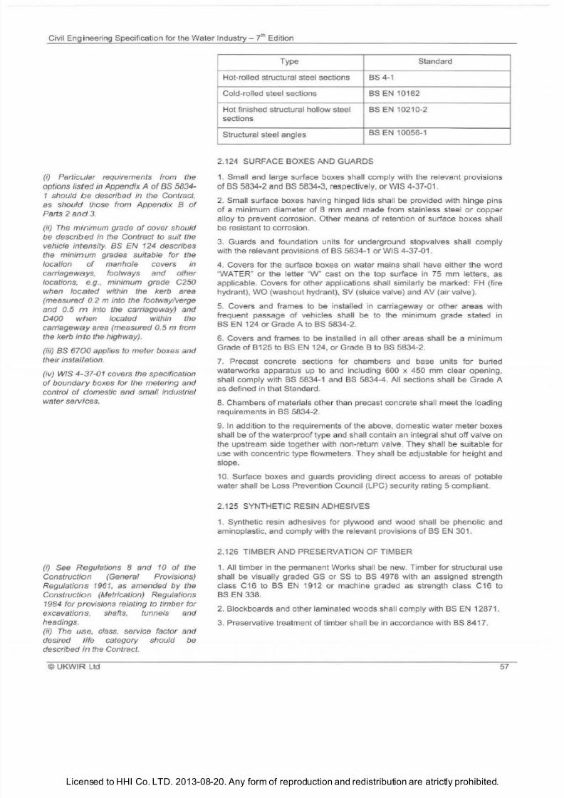
7/21/2019 The Civil Engineering Specification for the Water Industry 7th
http://slidepdf.com/reader/full/the-civil-engineering-specification-for-the-water-industry-7th 63/176Licensed to HHI Co. LTD. 2013-08-20. Any form of reproduction and redistribution are atrictly prohibited.
Civil Engineering Specification for
the
Water Industry - yt
h
Edition
i)
Particular requirements from the
options listed in
Appendix
A of BS 5834-
1 should
be
described in the Contract,
as should those from Appendix of
Parts 2 and 3.
ii)
The
minimum grade of cover should
be described in the Contract to suit the
vehicle intensity.
as
EN 124 describes
the minimum grades suitable for the
location of manhole covers in
carriageways, footways and other
locations, e.
g.
, minimum grade C250
when located within the kerb area
m easured 0.2 minto the footway/verge
and 0. 5 m into the carriageway) and
4 when located within the
carriageway area measured 0.5 m from
the kerb in to the highway).
iii) as 6700 applies to meter boxes and
their installation.
iv) WIS 4-37-01 covers the specification
of
boundary boxes for the metering and
control of domestic and small industrial
water services.
i) See Regulations 8
and
10
of
the
Construction General Provisions)
Regulations 1961 , as amended by the
Construction Metrication) Regulations
1984 for provisions relating to timber for
excavations, shafts, tunnels and
headings.
ii) The
use
, class, service factor and
desired life category should be
described in the Contract.
©UKWIR
Ltd
Type Standard
Hot-rolled structural steel sections BS 4 1
Cold-rolled steel sections
BS
EN
10162
Hot finished structural hollow steel BS
EN
10210
2
sections
Structural steel angles
BS
EN
10056-1
2.124 SURFACE BOXES AND GUARDS
1.
Small and large surface boxes shall comply with the relevant provisions
of BS 5834-2 and
BS
5834-3, respectively, or WIS 4·37-01.
2.
Small surface boxes having hinged lids sha
ll
be provided with hinge pins
of a minimum diameter of 8 mm and made from stainless steel
or
copper
alloy to prevent corrosion. Other means of retention of surface boxes shall
be resistant to corrosion.
3
Guards and foundation units for underground stopvalves shall comply
with the relevant provisions of
BS
5834-1 or WIS 4-37-01.
4. Covers for the surface boxes on water mains shall have either the word
WATER or the letter W cast
on
the top surface in
75
mm letters, as
applicable. Covers for other applications shall similarly be marked:
FH
{fire
hydrant), WO {washout hydrant), SV {sluice valve) and AV {air valve).
5. Covers and frames to be installed in carriageway or other areas with
frequent passage of vehicles shall be to
the
minimum grade stated in
BS
EN
124 or Grade A to BS 5834-2.
6.
Covers and frames to
be
installed in all other areas shall
be
a minimum
Grade of B 25to
BS EN
124, or Grade B to
BS
5834-2.
7.
Precast concrete sections for chambers and base units for buried
waterworks apparatus up to and
In
cluding 600 x 450
mm
clear opening,
shall comply with
BS
5834-1 and
BS
5834-4. All sections shall be Grade A
as defined in that Standard.
8.
Chambers of materials other than precast concrete shall meet the loading
requirements in BS 5834-2.
9
In addition to the requirements
of
the above, domestic water meter boxes
shall be of the waterproof type and shall contain
an
integral shut off valve on
the upstream side together with non-return valve. They shall
be
suitable for
use with concentric type flowmeters. They shall
be
adjustable for height and
slope.
10. Surface boxes and guards providing direct access to areas of potable
water shall be Loss Prevention Council {LPG) security rating 5 compliant.
2.125 SYNTHETIC RESIN ADHESIVES
1.
Synthetic resin adhesives for plywood and wood shall be phenolic and
aminoplastic. and comply with the relevant provisions of BS
EN
301.
2.126 TIMBER AND PRESERVATION
OF
TIMBER
1.
All timber in the permanent Works shall be new. Timber for structural use
shall
be
visually graded GS or SS to
BS
4978 with
an
assigned strength
class C16 to
BS
EN 1912 or machine graded as strength class C16 to
BS EN
338.
2.
Blackboards and other laminated woods sha ll comply with
BS EN
12871.
3. Preservative treatment of timber shall be in accordance with
BS
8417.
57
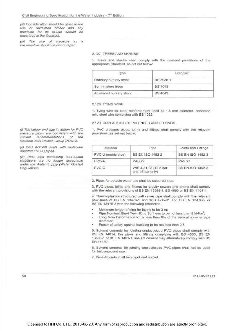
7/21/2019 The Civil Engineering Specification for the Water Industry 7th
http://slidepdf.com/reader/full/the-civil-engineering-specification-for-the-water-industry-7th 64/176Licensed to HHI Co. LTD. 2013-08-20. Any form of reproduction and redistribution are atrictly prohibited.
Civil Engineering Specification for the Water Industry 7th Edition
iii) Consideration should be given to the
use of reclaimed timber and any
provision for its re-use should be
described in the Contract.
iv) The use of creosote as a
preservative should be discouraged.
i) The colour and size limitation for PVC
pressure pipes are consistent with the
current recommendations of the
National Joint Utilities Group NJUG).
ii) WIS 4-31-08 deals with molecular
oriented
PVC 0
pipes.
iii) PVC pipe containing lead-based
stabilisers are
no
longer acceptable
under the Water Supply Water Quality)
Regulations.
58
2.127 TREES AND SHRUBS
1. Trees and shrubs shall comply with the relevant provisions
of
the
appropriate Standard, as set out below:
Type Standard
Ordinary nursery stock BS 3936-1
Semi-mature trees
BS4043
Advanced nursery stock
BS4043
2.128 TYING WIRE
1.
Tying wire for steel reinforcement shall be 1.6 mm diameter, annealed
mild steel wire complying with BS 1052.
2.129 UNPLASTICISED PVC PIPES AND FITIINGS
1. PVC pressure pipes, joints and fittings shall comply with the relevant
provisions, as set out below:
Material Pipe Joints and Fittings
PVC-U (metric blue)
BS EN
ISO 1452-2
BS EN
ISO 1452-3
PVC-A
PAS 27 PAS27
PVC-0 WIS 4-31-08 (12.5 bar BS EN ISO 1452-3
and 16 bar on ly
2.
Pipes for potable water use shall
be
coloured blue.
3.
PVC pipes, joints and fittings for gravity sewers and drains shall comply
with the relevant provisions of BS EN 13598-1 , BS 4660 or BS EN 1401-1.
4. Thermoplastics structured wall sewer pipe shall comply with the relevant
provisions of BS EN 13476-1 and WIS 4-35-01 and BS EN 13476-2 or
BS EN 13476-3 with the following properties:
Maximum length of pipe for laying to be 3 m;
Pipe Nominal Short Term Ring Stiffness to be not less than 8 kN/m
2
;
Long term Deformation to be less than 6 of the vertical nominal pipe
diameter;
Factor of safety against buckling to be not less than 2.5.
5. Solvent cements for jointing unplasticised PVC pipes shall comply with
BS
EN
14814. For pipes and fittings complying with BS 4660, BS
EN
13598-1
orBS
EN 1401-1, solvent cement may alternatively comply with BS
EN 14680.
6.
Solvent cements for jointing unplasticised PVC pipes shall not
be
used
for below-ground use.
7.
Push-fit joints shall
be
spigot and socket.
©UKWIR
Ltd
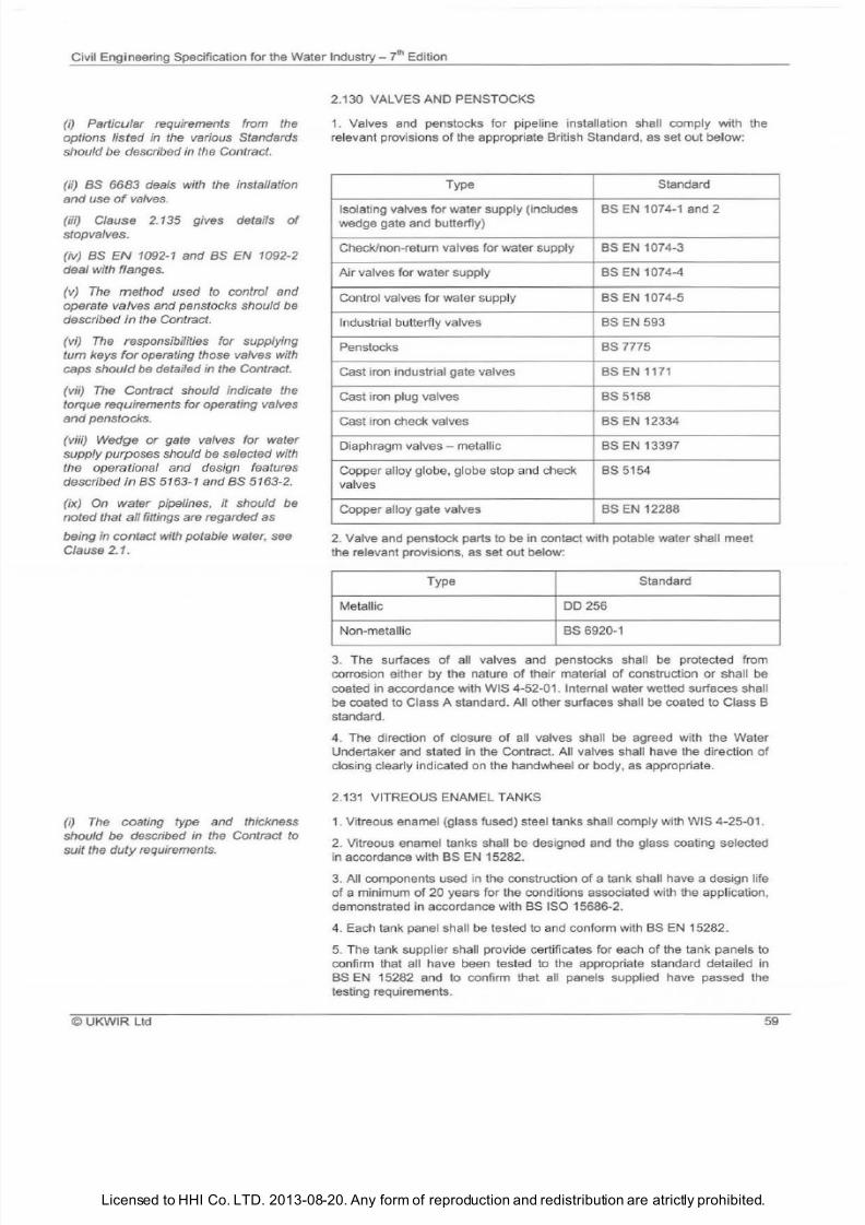
7/21/2019 The Civil Engineering Specification for the Water Industry 7th
http://slidepdf.com/reader/full/the-civil-engineering-specification-for-the-water-industry-7th 65/176Licensed to HHI Co. LTD. 2013-08-20. Any form of reproduction and redistribution are atrictly prohibited.
Civil Engineering Specification for the Water Industry 7th Edition
i) Particular requirements from the
options listed in the various Standards
should be described in the Contract.
ii)
as
6683 deals with
the
installation
and
use of
valves.
iii) Clause 2. 135 gives details of
stopvalves.
iv)
as N 1092-1
and BS N 1092-2
deal with flanges.
v) The method used to control and
operate valves and penstocks should be
described in the Contract.
vi) The responsibilities for supplying
turn keys
for
operating those valves with
caps should be detailed in the Contract.
vii)
The
Contract should indicate the
torque requirements for operating valves
and
penstocks.
viii) Wedge or gate valves for water
supply purposes should be selected
with
the operational and design features
described
in
BS 5163-1 and BS 5163-2.
ix) On water pipelines, it should be
noted that all fittings are regarded as
being in contact with potable water, see
Clause 2.1.
i) The coating type and thickness
should be described in the Contract to
suit the
duty
requirements.
UKWIR Ltd
2.130 VALVES AND PENSTOCKS
1.
Valves and penstocks for pipeline installation shall comply with the
relevant provisions of the appropriate British Standard, as set out below:
Type Standard
Isolating valves for water supply includes BS EN 1074-1 and 2
wedge gate and butterfly)
Check/non-return valves for water supply BS EN 1074-3
Air valves for water supply BS EN 1074-4
Control valves for water supply
BS EN 1074-5
Industrial butterfly va lves BS EN 593
Penstocks
BS 7775
Cast iron industrial gate valves BS
EN
1171
Cast iron plug valves BS 5158
Cast iron check valves BS EN 12334
Diaphragm valves - metallic BS
EN
13397
Copper alloy globe, globe stop and check BS 5154
valves
Copper alloy gate valves BS
EN
12288
2
Valve and penstock parts to be in contact with potable water shall meet
the relevant provisions, as set out below:
Type Standard
Metallic
DO
256
Non-metallic BS 6920-1
3 The surfaces of all valves and penstocks shall be protected from
corrosion either by the nature of their material of construction or shall
be
coated in accordance with WIS 4-52-01. Internal water wetted surfaces shall
be coated to Class A standard. All other surfaces shall be coated to Class B
standard.
4 The direction of closure of all valves shall be agreed with the Water
Undertaker and stated in the Contract. All valves sha
ll
have the direction
of
closing clearly indicated on the handwheel or body,
as
appropriate.
2.131 VITREOUS ENAMEL TANKS
1 Vitreous enamel glass fused) steel tanks shall comply with WIS 4-25-01.
2 Vitreous enamel tanks shall be designed and the glass coating selected
in accordance with BS EN 15282.
3. All components used in the construction of
a tank shall have a design life
of a minimum of 20 years for the conditions associated with the application,
demonstrated in accordance with BS ISO 15686-2.
4. Each tank panel sha ll be tested to and conform with BS EN 15282.
5
The tank supplier shall provide certificates for each of the tank panels to
confirm that all have been tested to the appropriate standard detailed in
BS EN 15282 and to confirm that all panels supplied have passed the
testing requirements.
59
7/21/2019 The Civil Engineering Specification for the Water Industry 7th
http://slidepdf.com/reader/full/the-civil-engineering-specification-for-the-water-industry-7th 66/176Licensed to HHI Co. LTD. 2013-08-20. Any form of reproduction and redistribution are atrictly prohibited.
Civil Engineering Specification for the Water
Industry
t hEdition
i) IGN 4-11-01 deals with vitrified clay
pipes and fittings.
ii) The type of joint
and
jointing
materials for extra chemically-resistant
pipes should be described in the
Contract.
i) The type, size, thickness
and
colour
of
tiles should be described in the
Contract.
i) In certain areas. supplementary
mains carrying non-potable water have
been laid.
The
use of this water with
cement or in contact with potable water
mains
and
installations
has
been
prohibited.
ii) Where potable water
s
not available,
then alternative provision should be
detailed in the Contract. BS N 1008
gives details
of
suitability tests for water
for use in
mak
i
ng
concrete.
i)
On potable water pipelines it should
be
noted that all fittings are regarded
as
being in contact with potable water. see
Clause 2.1.
60
6
Where it is necessary to construct pipework through the tank wall, the
tank supplier shall provide galvanised steel, PN16 flanged connectors,
complete with gaskets, internally and externally, which are compatible with
the curvature
of the
tank. All cut-outs or sheet penetrations shall
be
formed
in the raw steel sheet prior to the application of the vitreous enamel coating.
7
Where tanks are to
be
used for mixing
of
fluids, the tank shall
be
designed to withstand the dynamic loads from mixers and to resist abrasion
from material within the tank contents e.g., grit). This may take the form
of
a sacrificial battle, or concrete battle in front of the tank wall.
8 Where man entry into the tank is required at the external ground level,
there shall be an 800 mm minimum clear opening. A bolted man entry hatch
shall
be
provided unless otherwise stated in the Contract. The high strength
low alloy HSLA) steel hatch door shall be protected against corrosion to
ensure a design life equivalent to the tank. All manways shall be supplied
with davit arms.
2.132 VITRIFIED CLAY PIPES AND PIPELINE FITTINGS
1
Vitrified clay pipes and pipeline fittings , including extra chemically
resistant pipes and fittings, shall comply with the relevant provisions of
BS 65
orBS
EN 295-1 .
2. Vitrified clay jacking pipes shall conform to BS
EN
295-7.
2.133 WALL TILES
1 Ceramic tiles for internal walls shall comply with the relevant provisions of
BS EN 14411
.
2.134 WATER
1
Water for use with cementitious materials, or in contact with potable
water mains and installations, shall be
of
potable quality.
2.135 WATER FITTINGS AND APPLIANCES
1 Water fittings and appliances shall comply with the relevant provisions of
the appropriate Standard, as set out in the following table:
©UKWIR
Ltd
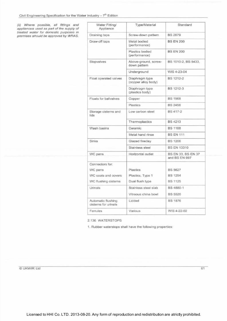
7/21/2019 The Civil Engineering Specification for the Water Industry 7th
http://slidepdf.com/reader/full/the-civil-engineering-specification-for-the-water-industry-7th 67/176Licensed to HHI Co. LTD. 2013-08-20. Any form of reproduction and redistribution are atrictly prohibited.
Civil Eng i neering Specification for the Water
Industry-
7
Edition
ii
Where possible, all fittings and
appliances used as parl of the supply
of
treated water for domestic purposes
in
premises should be approved
y
WRAS.
Water
Fitting/
Appliance
Draining taps
Draw-off taps
Stopvalves
Float operated valves
Floats for ballvalves
Storage cisterns and
lids
Wash basins
Sinks
we
pans
Connectors for:
we pans
WC seats and covers
we flushing c isterns
Urinals
Automatic flushing
cisterns for urinals
Ferrules
2.136 WATERSTOPS
Type
/Material
Standard
Screw-down pattern
BS
2879
Metal bodied BS EN 200
performa
nce)
Plastics bodied BS EN
200
perfor
mance
)
Above-ground, screw- BS
1010-2
BS
5433
down pattern
Underground WIS
4-23-04
Diaphragm type BS 1212-2
cop per alloy body)
Diaphragm type BS
1212-3
plastics body)
Copper
BS
1968
Plasti
cs
BS
2456
Low carbon steel BS 417-2
Thermoplastics BS
4213
Ceramic BS
1188
Metal hand rinse BS EN
Glazed fireclay BS
1206
Stainless steel BS EN
13310
Horizontal outlet BS EN BS EN
7
and BS EN 997
Plastics BS
5627
Plastics,
Type 1 BS 1254
Dua
l flush type BS
1125
Stainless steel slab BS 4880-1
Vitreous china bowl
BS 5520
Lidded BS
1876
Various WIS
4-22-02
1. Rubber waterstops shall have the foll
ow
ing properties :
©
UKWIR
l td
6
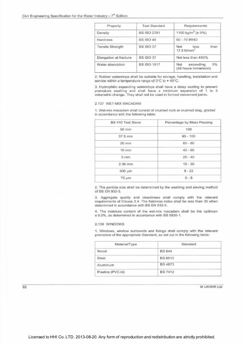
7/21/2019 The Civil Engineering Specification for the Water Industry 7th
http://slidepdf.com/reader/full/the-civil-engineering-specification-for-the-water-industry-7th 68/176
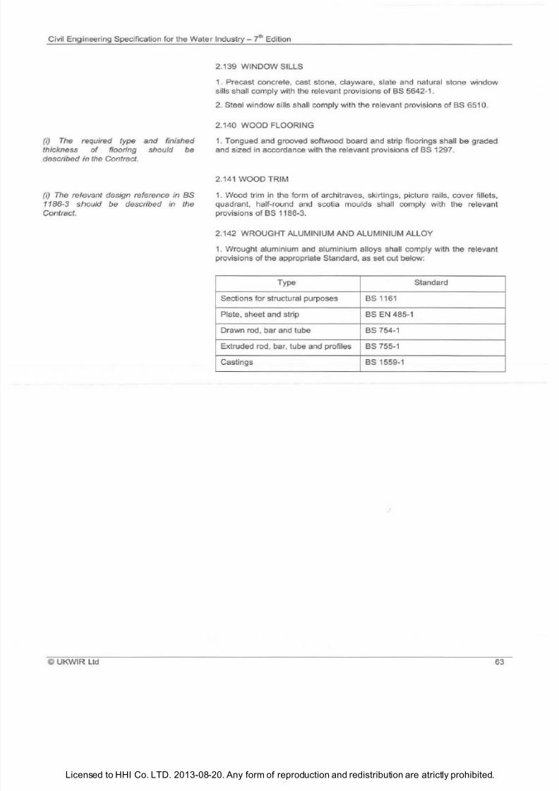
7/21/2019 The Civil Engineering Specification for the Water Industry 7th
http://slidepdf.com/reader/full/the-civil-engineering-specification-for-the-water-industry-7th 69/176Licensed to HHI Co. LTD. 2013-08-20. Any form of reproduction and redistribution are atrictly prohibited.
Civil Engineering Specification for the Water Industry 7
t
Edition
i) The required type and finished
thickness
o
flooring should be
described in
the
Contract.
i) The relevant design reference in BS
1186-3 should be described in the
Contract.
© UKWIR Ltd
2.139 WINDOW SILLS
1
Precast concrete cast stone clayware slate and natural stone window
sills shall comply with the relevant provisions of
BS
5642-1.
2 Steel window sills shall comply with the relevant provisions of BS •651 0
2.140 WOOD FLOORING
1. Tongued and grooved softwood board and strip floorings shall be graded
and sized in accordance with the relevant provisions
of BS
1297.
2.141 WOOD TRIM
1
Wood trim in
the
form of architraves skirtings picture rails cover fillets
quadrant half-round and scotia moulds sha
ll
comply with the relevant
provisions
of
BS 1186-3.
2.142 WROUGHT ALUMINIUM AND ALUMINIUM ALLOY
1 Wrought aluminium and aluminium alloys shall comply with the relevant
provisions of the appropriate Standard as set out below:
Type
Standard
Sections for structural purposes
BS 1161
Plate sheet and strip BS EN 485-1
Drawn rod bar and tube
BS
754-1
Extruded rod bar tube and profiles
BS
755-1
Castings
BS
1559-1
63

7/21/2019 The Civil Engineering Specification for the Water Industry 7th
http://slidepdf.com/reader/full/the-civil-engineering-specification-for-the-water-industry-7th 70/176Licensed to HHI Co. LTD. 2013-08-20. Any form of reproduction and redistribution are atrictly prohibited.
ivil Engineering Specification for the WaterIndustry
th
Edition
6
©UKWIR l td
7/21/2019 The Civil Engineering Specification for the Water Industry 7th
http://slidepdf.com/reader/full/the-civil-engineering-specification-for-the-water-industry-7th 71/176Licensed to HHI Co. LTD. 2013-08-20. Any form of reproduction and redistribution are atrictly prohibited.
Civil Engineering Specification for the Water Industry 7
h Edition
The Notes for Guidance are not part
of
the Specification.
i) The
following publications give
recommendations as to standards
of
good practice for excavation:
as 6031;
as 6164;
Report R97, Trenching Practice ,
published by CIRIA; and
Technical Note
TN95
Proprietary
Trench Support systems , published by
CIRIA.
(ii) A definition of rock shall be included
in the Contract.
(iii) The relevant Highway Reinstatement
Specification Roles should be defined in
the Contract.
(iv) ny special requirements for Site
clearance or for the disposal of
excavated materials should be
described in the Contract.
v)
The Contract should describe the
extent
o
any excavations where
battered sides will be permitted. A detail
of
the allowable cross-section should be
given.
vi) Excavation in carriageways should,
wherever possible, be located such that
the edge of
the
opening is at least 1 m
from the edge of
the
carriageway.
(vii) Care should be taken when siting
spoil heaps to avoid damaging trees by
impinging on their root spread.
(viii) Excavated material for disposal
off
Site
would
normally be classified as
controlled waste and the Client, under
the Environmental Protection Act 1990,
has a
duty of
care to ensure that the
Works are carried out in compliance with
the legislation relating to the treatment,
keeping
or
disposal of such material.
(ix) Reference should be made to The
Financing
ct
1996 (Landfill
Tax).
x) Stored excavated granular material
may require draining to achieve
acceptable water content.
©UKW
IR l td
SECTION 3
EXCAVATION BACKFILLING AND RESTORATION
3.1
EXCAVATION
1. Operations shall be carried out in such a manne r as to prevent damage
to, or dete
ri
oration of, the formation of excavations.
2. Excavation in roads and streets shall be ca rried out in accordance with
the relevant Highway Reinstatement Specification.
3. Excavations in locations where services may be encountered shall be
carried out in accordance with HSG 47 Avoiding Danger from Underground
Services .
4. Trenches shall be excavated so that the effective width is maintained
within any limit imposed by the design
of
the pipeline. The sides
of
excavations shall be adequately supported at all times and, except where
described in or permitted under the Contract, shall not be battered.
5. Unsuitable ground or damaged surfaces below formation shall be
excavated and then filled to formation level, with the material shown on the
drawings
or
otherwise specified in the Contract. Any void that results from
over-excavation shall be filled with the material stated in the Contract.
6. Excavated granular material which can be reused shall be kept separate
from excavated cohesive materials.
7. Trenches in rock for flexible pipes shall be excavated to provide a
minimum clearance
of
100 mm around the outside
of
pipe barrels and joints
for pipes up
to
100 mm nominal bore, and 150 mm for pipes of larger
nominal bore. For rigid pipes the minimum clearance shall be 200 mm.
8. Trenches for pipes ca rrying water under pressure shall, except where
otherwise described in the Contract, be excavated to a sufficient depth to
ensure a minimum cover
of
900 mm
to th
e top of the pipes.
6
7/21/2019 The Civil Engineering Specification for the Water Industry 7th
http://slidepdf.com/reader/full/the-civil-engineering-specification-for-the-water-industry-7th 72/176Licensed to HHI Co. LTD. 2013-08-20. Any form of reproduction and redistribution are atrictly prohibited.
Civil Engineering Specification for the Water Industry 7l Edition
i) It
is advisable to make an
assessment
of
soil stacking
requirements in cases where topsoil
quality is important, and to provide
accordingly in
the
Contract
i)
ny
requirements for prevention of
the deposition of silt and/or protection
from erosion should be set out in the
Contract.
i)
Any special requirements for
backfilling around mains and services
should be described in the Contract.
ii) ny particular requirements for the
materials
to
be used for backfilling
should be described in the Contract.
66
3.2 RELAYING TURF
1 Good practice dictates that turves shall be green when cut, they shall be
kept moist and shall be re-laid in suitable weather conditions
2 The level of topsoil beneath turves shall be such that the final grass
surface after compaction shall be flush with the ad joining grass surface.
3.3 TOPSOIL FOR RE-USE
1
Topsoil shall mean the top layer of soil that can support vegetation.
It
shall include all turf not required for relaying or not acceptable for turfing
under Clause 3.2
2 Topsoil shall be removed from the areas described in the Contract and,
where required for re-use, shall
be
stockpiled separately and kept free from
weeds.
3 Handling of topsoil shall be in accordance with BS 3882.
4 Topsoil stripping, stockpiling and replacement shall be conducted
in
such
a manner as
to
minimise damage to the soil structure.
3.4 DEALING WITH WATER
1 Water shall not be allowed to lie anywhere within excavations, unless so
required under the Contract. Any drainage sumps required shall, where
practicable, be sited outside the area excavated for the Works and shall be
re-filled with approved material to the level of the underside of the adjacent
permanent Works.
2 All necessary precautions shall be taken to prevent any adjacent ground
from being adversely affected by loss of fines through any dewatering
process.
3 Groundwater shall not be allowed to enter mains to be used for the
conveyance of potable water.
4 The Contractor shall provide method statements and details of pollution
prevention measures relating to the control and disposal
of
groundwater
from de-watering operations. Discharging sha ll be subject to the Contractor
obtaining prior written approval from the appropriate consenting body.
3.5 TEMPORARY DRAINS
1 Where temporary drains are required, they shall be laid in a narrow
trench or grip formed below the bottom of the excavation
in
an approved
position. The pipes shall be open-jointed and shall be surrounded with free
draining granular material.
2. When no longer required, temporary drains shall be removed or sealed.
3 When sealing temporary drains, grouting pipes shall be inserted
in
the
line of the temporary drains at intervals not exceeding 25
m The drains
shall be solidly filled with grout (Class G3 or G4) and the grouting pipes cut
off on completion of the filling. Care shall be taken to avoid impregnation of
the granular bedding material around the main pipeline.
3.6 BACKFILLING
1 Backfilling shall, wherever practicable, be undertaken immediately the
specified operations preceding it have been completed. Backfilling shall not,
however, be commenced until the Works to be covered have achieved a
strength sufficient to withstand all loading imposed thereon.
2
Backfilling sha
ll be
undertaken
in
such a manner as to avoid
un
even
loading or damage.
©UKWIR Ltd
7/21/2019 The Civil Engineering Specification for the Water Industry 7th
http://slidepdf.com/reader/full/the-civil-engineering-specification-for-the-water-industry-7th 73/176Licensed to HHI Co. LTD. 2013-08-20. Any form of reproduction and redistribution are atrictly prohibited.
Civil Engineering Specification for the Water Industry - 7 ' Edition
iii) No materials should be stored on
roofs
of
tanks without the written
approval o he Client.
iv) When considering the requirements
for backfilling to water-retaining
structures, reference should be made to
Section
7
4
of
his Specification.
i) Any particular requirements for the
reinstatement method, materials and
depths
of
layers should be described in
the Contract.
ii) Reinstatement of surface boxes is
covered in Clause 5.
.
iii) Reference should be made to the
New Roads and Street Works Act.
i) Where the relevant Highways
Reinstatement Specification is
inappropriate, the reinstatement should
be described in the Contract.
ii) Any discussions with the landowner
should be carried out through a land
agent.
i) Any special grass seed mixtures
required, differing from those specified
in Clause
2.56
should be described in
the Contract.
ii) Any requirements to apply fertiliser
should be described in the Contract.
iii) Any special provisions for the
reinstatement of land should be set out
in the Contract, including the use
of
deep
ploughing where overcompaction
of
he
unpaved land has occurred.
©UKW R Ltd
3. Filling material to excavations not situated in the highway sha ll be in
accordance with Clause 2.49, placed and compacted to form a stable
backfi
ll
.
4. Excavations in roads and streets shall be filled above the level of any
pipe surround required, in accordance with the relevant Highway
Reinstatement Specification.
5.
Where the excavations have been supported and the supports are to be
removed these, where practicable, shall be withdrawn progressively as
backfilling proceeds, in such a manner as to minimise the danger of
collapse, and all voids formed behind the supports shall be carefully filled
and compacted.
3.7 REINSTATEMENT OF MAINTAINABLE HIGHWAYS
1. Reinstatement
of
roads and streets (including carriageways footways,
footpaths, cycle tracks and verges) which are maintainable highways shall
be undertaken in accordance with the relevant provisions of the re levant
Highway Reinstatement Specification.
2. Road categories and reinstatement requirements shall be obtained from
the relevant Highway Authority and comply with the New Roads and Street
Works Act.
3. Ke rbs, channels edgings and quadrants disturbed by the Works shall be
re-laid with existing units, providing they are not damaged. Where existing
units are not suitable for re-use, replacement units
of
similar texture , colour
and type, consistent with those adjacent and complying with the relevant
provisions
of Clause 2.35 or 2.98, as appropriate, shall be provided.
4.
The re-laying of kerbs, channels, edgings and quadrants shall be in
accordance wi
th
Clause 8.10. In-situ kerbs and channels shall be reinstated
to conform with ad joining kerbs and channels.
3.8 REINSTATEMENT OF NON-MAINTAINABLE HIGHWAYS
1. Non-maintainable highways shall, except where otherwise stated in the
Contract, be reinstated in accordance with the relevant provisions
of
Clause 3.7.
3.9 REINSTATEMENT OF UNPAVED LAND
1. Proposals for reinstatement shall be discussed with the landowner prior
to any work commencing (see Section 1. 7). Subso il ing of the working strip
is required, unless otherwise stated in the Contract.
2. The surface
of
all land affected shall be broken up, to a depth
of at
least
300 mm, and stones and extraneous material greater than 50 mm in size
cleared before topsoil is replaced. The land shall be cultivated and restored
as closely as possible to its original condition.
3.
Surfaces to be sown with grass seed shall be reduced
to
a fine tilth and
cleared
of
stones and extraneous material greater than 50 mm in size. The
seed shall be sown at the proper season, evenly distributed and applied at a
rate of not less than the quantities given in the following table:
67
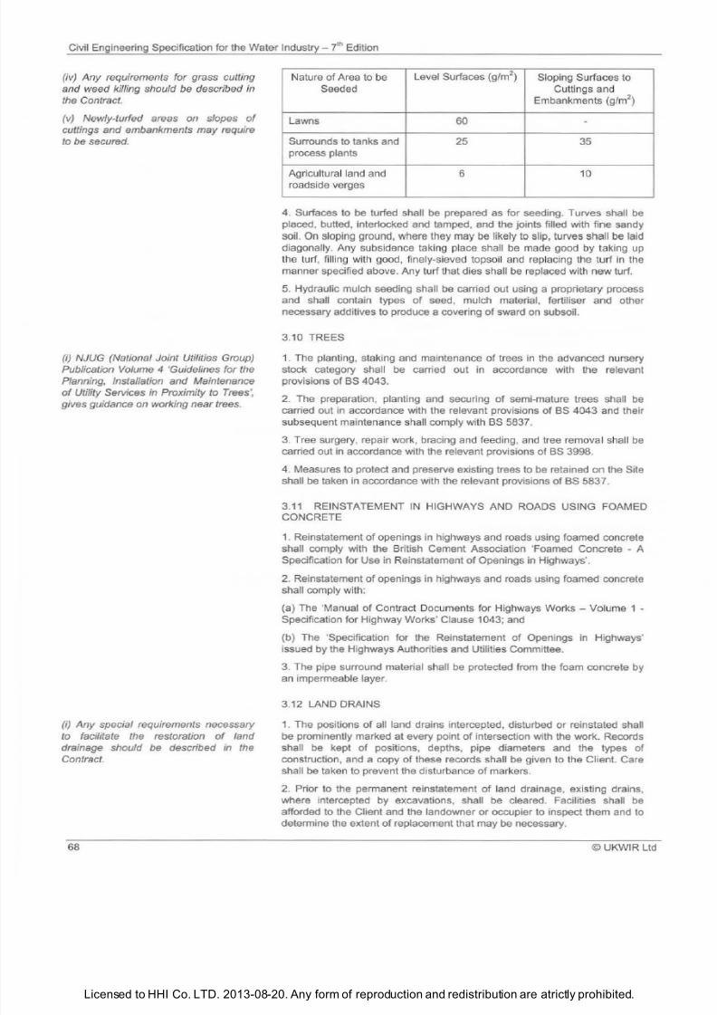
7/21/2019 The Civil Engineering Specification for the Water Industry 7th
http://slidepdf.com/reader/full/the-civil-engineering-specification-for-the-water-industry-7th 74/176Licensed to HHI Co. LTD. 2013-08-20. Any form of reproduction and redistribution are atrictly prohibited.
Civil Engineering Specification for the Water Industry -
7 h
Edition
iv) ny requirements for grass cutting
and weed killing should be described in
the Contract.
v) Newly-turfed areas on slopes of
cuttings and embankments may require
to be secured.
i) NJUG (National Joint Utilities Group)
Publication Volume 4 Guidelines for the
Planning, Installation and Maintenance
of Utility Services in Proximity to Trees ,
gives guidance on working near trees.
i) ny special requirements necessary
to facilitate the restoration
of land
drainage should be described in the
Contract.
68
Nature of Area to be
Level Surfaces (g/m
2
Sloping Surfaces to
Seeded Cuttings and
Embankments (g/m
2
Lawns
60
-
Surrounds to tanks and 25
35
process plants
Agricultural land and
6
10
roadside verges
4. Surfaces
to be
turfed shall be prepared as for seeding. Turves shall be
placed, butted, interlocked and tamped, and the joints filled with fine sandy
soil. On sloping ground, where they may be likely to slip, turves shall be laid
diagonally. Any subsidence taking place shall be made good by taking up
the turf, filling with good, fine l
y s
ieved topsoil and replacing the turf in the
manner specified above. Any turf that dies shall be replaced with new turf.
5. Hydraulic mulch seeding shall be carried out using a proprietary process
and shall contain types
of
seed, mulch material, fertiliser and other
necessary additives to produce a covering
of
sward on subsoil.
3.10 TREES
1.
The planting, staking and
ma
intenance
of
trees in the advanced nursery
stock category shall be carried out in accordance with the relevant
provisions
of
BS 4043.
2. The preparation, planting and securing
of
semi-mature trees shall be
carried out
in
accordance with the relevant provisions
of
BS
4043 and their
subsequent maintenance shall comply with BS 5837.
3. Tree surgery, repair work, bracing and feeding, and tree removal shall be
carried out in accordance with the relevant provisions
of BS
3998.
4.
Measures to protect and preserve existing trees to be retained on the Site
shall
be
taken in accordance with the relevant provisions
of BS
5837.
3.11 REINSTATEMENT IN HIGHWAYS AND ROADS USING FOAMED
CONCRETE
1. Reinstatement
of
openings in highways and roads using foamed concrete
shall comply with the British Cement Association Foamed Concrete - A
Specification for Use in Reinstatement
of
Openings in Highways .
2. Reinstatement
of
openings in highways and roads using foamed concrete
shall comply with:
(a) The Manual
of
Contract Documents for Highways Works - Volume 1 -
Specification for Highway Works Clause 1043; and
(b) The Specification for the Reinstatement
of
Openings in Highways
issued by the Highways Authorities and Utilities Committee.
3.
The pipe surround material shall be protected
from
the foam concrete by
an impermeable layer.
3.12 LAND DRAINS
1. The positions
of
all land drains intercepted, disturbed or reinstated shall
be prominently marked at every point
of
intersection with the work. Records
shall be kept
of
positions, depths, pipe diameters and the types
of
construction, and a copy
of
these records shall
be
given to the Client. Care
shall be taken to prevent the disturbance
of
markers.
2. Prior to the permanent reinstatement
of
land drainage, existing drains,
where intercepted by excavations, shall be cleared. Facilities shall be
afforded to the Client and the landowner or occupier to inspect them and to
determine the extent
of
replacement that may be necessary.
©UKW R
Ltd
7/21/2019 The Civil Engineering Specification for the Water Industry 7th
http://slidepdf.com/reader/full/the-civil-engineering-specification-for-the-water-industry-7th 75/176Licensed to HHI Co. LTD. 2013-08-20. Any form of reproduction and redistribution are atrictly prohibited.
Civil Eng ineering Specification for
the
Water
Industry
7 ' Edition
i)
This
is
a general Clause
to
cover
filling which performs no specific load-
bearing or structural role. A more
thorough specification may be
necessary in other cases see, for
instance, the Highways Agency s
Specification for Highway Works?.
i) It may be necessary for the Contract
to describe safe values for vibrational
amplitude
and
peak parlicle velocity.
(ii)
For further guidance on blasting
with
respect to tunnelling works, see British
Tunnelling Society and Institution of Civil
Engineers Specification for Tunnelling ,
Clause 3 9.
i)
The ICE Specification for Piling and
Embedded Retaining
Walls
includes
Associated Guidance on Contract
Documentation and Measurement .
i)
Any furlher information required
should be stated
in
the Contract.
(ii) Reference should be made to
The
Health and Safety Executive guidance
on demolition works (www.hse.gov.uk).
© UKWIR Ltd
3.
The backfill
of
intercepting excavations shall be compacted in 200 mm
layers, to give a firm bearing immediately before replacement pipes are laid,
and shall
be
brought up to the level
of
the underside
of
the land drains or
of
any support to be provided.
4
The affected land drains sha
ll be
cut back into firm ground until, in each
case, a section is exposed which is unaffected by the Works.
5
Replacement pipes or support beams shall bear on undisturbed ground
for at least 500 mm at each end. The replacement pipes shall
be
of the
same internal diameter as the sections
of
drain which they replace and shall
be properly connected at each end.
3.13 FILLING ABOVE GROUND
1 Embankments and other areas of fill shall be formed of suitable materials
capable of normal compaction to form a stable fill, deposited and
compacted as soon as practicable after excavation in layers
of
thickness
appropriate to the compaction plant used.
2
The filling shall, where practicable,
be
built up and compacted evenly,
and shall be maintained at all times with a sufficient camber or cross fall and
a surface sufficiently even to enable surface water to drain readily from it.
3.14 BLASTING
1 The procedure for using explosives shall be stated in the Contract.
2 Where blasting is proposed adjacent to a building or other structure,
existing or under construction, the agreed safe values
of
vibrational
amplitude and peak particle velocity shall not
be
exceeded.
3
The use
of
electrical detonators
in
the vicinity
of
static and mobile radio
transmitters, including normal radio and television broadcasting stations and
radar units associated with aircraft movements, shall comply with the
provisions
of BS
6657.
4
The handling, transport and use
of
explosives shall be in accordance with
the relevant provisions of BS 5607. Explosives shall be used in the
quantities and manner recommended by the manufacturer.
3.15 PILING
1 The Specification for piling shall be the 'Specification for Piling and
Embedded Retaining Walls', published by the Institution
of
Civil Engineers
in 1996.
3.16 DEMOLITION
1.
Demolition shall be carried out in accordance with BS 6187.
69

7/21/2019 The Civil Engineering Specification for the Water Industry 7th
http://slidepdf.com/reader/full/the-civil-engineering-specification-for-the-water-industry-7th 76/176Licensed to HHI Co. LTD. 2013-08-20. Any form of reproduction and redistribution are atrictly prohibited.
Civil Engineering Specification for the Water Industry hEdition
7
©UKW R
Ltd
7/21/2019 The Civil Engineering Specification for the Water Industry 7th
http://slidepdf.com/reader/full/the-civil-engineering-specification-for-the-water-industry-7th 77/176Licensed to HHI Co. LTD. 2013-08-20. Any form of reproduction and redistribution are atrictly prohibited.
Civil Engineering Specification for the Water Industry ? h Edition
The Notes for Guidance are not part of
the Specification.
i) Where it
s
not practicable to carry out
full-scale trials, special reference should
be made in the Contract to laboratory
scale mixes.
(ii) Sufficient information should be
derived from the initial testing to ensure
that the concrete will meet the specified
requirements. It may also be necessary
to specify water absorption tests for
structures designed to retain an
aqueous liquid.
i) ny requirements for placing concrete
in special sequence, e.g.,
by
alternate
bay
construction, should be described in
the Contract.
(ii) ''Adequate in the context of notice to
the Client should be sufficient time
to
allow the Client to fulfil their quality
management obligations. The minimum
time period should be agreed at the
commencementof he Contract.
(iii) ny variations to the times
in
Clause
4.5.3 should be specified in the
Contract.
(iv) Any requirements for testing fresh
concrete should
be
specified
as in
Clause 2.20.5.
©UKW
IR
l td
SECTION
CONCRETING AND FORMWORK
4 1 SUPPLY OF INFORMATION
1 Before any concrete is supplied and not less than 7 days before the start
of the concrete production all pertinent information specified in BS EN 206-
1 2000 Clause 7.2 and
BS
8500-2:2006 Clause 5.2 shall
be
exchanged and
agreed with the Producer.
4.2
IN
ITIAL TESTING
1
Initial testing shall be undertaken for each classification of structural
concrete.
2
Such testing shall
be
in accordance with
BS
EN
206-1 :2000 Clause 9.5
Clause 10 and Annex A.
4 3 IDENTITY TESTING
1
Where identity testing is specified for the testing of slump flow and air
content
of
individual batches it shall be undertaken in accordance with BS
8500-1.
2 Where specified identity testing for strength shall be carried out in
accordance with Clause 2.20.5.
4 4
POROUS NO-FINES CONCRETE
1 The concrete shall not be mechanically vibrated or excessively worked
when placed.
4.5 TRANSPORTING PLACING AND COMPACTING
1 Concrete shall
be
transported from the mixer in accordance with BS
8500-2 and placed in the Works as rapidly as practicable by methods which
will prevent the segregation or loss of any
of
the ingredients and will
maintain the required consistency. It shall
be
deposited as nearly as
practicable in its final position and all equipment for transporting concrete
shall be kept clean.
2 Adequate notice shall be given to the Client of the intention to commence
concreting.
3
Concrete shall be delivered to Site within the times specified in Clause
14.2 of
BS
8500-2: 2006.
4. Concrete shall be thoroughly compacted in its final position within 30
minutes of commencing discharge. The plant used for compaction shall be
operated continuously during the placing of each batch of concrete until the
expulsion of air has virtually ceased and in a manner which does not
promote segregation
of
the ingredients.
5 Whenever vibration has to be applied externally the design of formwork
and disposition
of
vibrators shall be such as to ensure efficient compaction
and to avoid surface blemishes.
71
7/21/2019 The Civil Engineering Specification for the Water Industry 7th
http://slidepdf.com/reader/full/the-civil-engineering-specification-for-the-water-industry-7th 78/176Licensed to HHI Co. LTD. 2013-08-20. Any form of reproduction and redistribution are atrictly prohibited.
Civil Engineering Specification for the Water
Industry i h
Edition
i) For further information see Winter
Concreting
,
published
by
Concrete
Information Ltd in 1985.
(i) The Contract should specify a
reduced upper temperature
i f
the design
of
the structure requires a lower
temperature, i.e., to minimise thermal
cracking on large pours.
(i) Consideration
may
have
to
be given
to measures to prevent thermal cracking
where a temperature differential in
excess
of
2o•c is likely to occur, e.g. , by
extending striking times for the
form work.
(i)
as
5975 gives recommendations as
to standards of good practice in
formwork construction.
(ii) The positioning and detailing
of
movement joints should be described in
the Contract.
(iii)
ny
special conditions relating
to
the
re-use
of
forms, insofar as the materials
of
construction and repairs between
uses may affect the colour and surface
finish
of
exposed surfaces, should be
72
4.6
CONCRETING IN COLD WEATHER
1.
Concreting
at
ambient temperatures below
2•c
may be carried out only if
the following conditions are met:
a)
the
aggregates and water used
in
the mix shall be free from snow, ice
and frost;
b) before placing concrete, the formwork, reinforcement and any surface
with which the fresh concrete will be in contact shall
be
free from snow, ice
and frost and shall be at a temperature above
o•c;
c) the initial temperature
of
the concrete at the time
of
placing shall be
at
least 5•c as defined in BS EN 206-1:2000 Section 5.2.8 Lower Limit;
d) the temperature at the surface
of
the concrete shall be maintained at not
less than
5•c
at any point until the concrete reaches a strength
of 5
N/mm
2
as confirmed by tests on cubes matured under similar conditions; and
e) temperatures at the surface
of
the concrete sha ll be measured where
the lowest temperature is expected.
2.
Precautions shall be taken to prevent the temperature
of
any concrete
falling to
o·c
during the first five days after placing.
4.7 CONCRETE TEMPERATURE
1. The resultant temperature of the combined materials in any batch of
concrete at
the
point and time
of
delivery to the Works shall not exceed the
upper limit as stated in BS 8500-2. Cement sha ll not be permitted to come
into contact with water at a temperature greater than 6o•c.
2.
Where the temperature
of
the fresh concrete is likely to exceed that
specified in
Clause 4.7.1, concreting shall not be permitted unless stated
in
the Contract.
4 8
CURING
1.
Curing
of
concrete shall
be
carried out in accordance with
BS
EN 13670
Curing Class 2.
2. In cold weather, when
the
temperature
of
freshly-placed concrete may
approach o•c cold water curing shall not be employed.
3.
Components which are intended to have a similar exposed surface finish
shall be cured in the same manner.
4.9 RECORDS OF CONCRETING
1.
Up-to-date records
of
the dates and times when concreting is carried out ,
and of the weather and temperatures at those times, shall be kept. The
records shall
be
available for inspection.
2. Sufficient records shall be maintained to enable every batch of concrete
and its location within the Works to be identified.
4.10 CONSTRUCTION OF FORMWORK
1. Formwork shall be sufficiently rigid and tight to prevent loss
of
mortar
from the concrete and to maintain the correct position , shape and
dimensions
of
the finished work. It shall be so constructed
as
to be
removable from the cast concrete without shock or damage.
2.
The forms shall be capable of producing a consistent quality of surface,
as described
in
the Contract.
3. Where holes are required in forms to accommodate projecting
reinforcement, fixing devices or other built-in items, precautions shall be
taken to prevent loss
of
the mortar matrix.
4. Formwork shall give access for the preparation
of
joint surfaces before
©
UKWIR Ltd
7/21/2019 The Civil Engineering Specification for the Water Industry 7th
http://slidepdf.com/reader/full/the-civil-engineering-specification-for-the-water-industry-7th 79/176Licensed to HHI Co. LTD. 2013-08-20. Any form of reproduction and redistribution are atrictly prohibited.
Civil Engineering Specification for the Water Industry 7
1
h Edition
described in the Contract.
(iv) ny special requirements regarding
chamfers to internal angles should be
described in the Contract.
(i) s the removal of formwork is
dependent upon the method
of
working,
the Contract may state a formal
procedure for determining striking times,
based on CIRIA Report R136.
(ii) Interpretation of CIRIA Report R136
should be in accordance with the
following:
(a) for
membe
rs with URough finish , the
requirements applicable to
F1
and F2
finish apply.
(b) for members with Fair finish or Fair
worked finish'; the requirements
applicable to F3 and F4 finish apply.
(iii)
Rough
finish : Fair finish and Fair
worked finish are described in Clause
4.22 (i).
(iv)
It should
be noted that 11 hours at
1s•c is equivalent to:
8 hours at 20 C
15
hours at
to
•c
24
hours at
SOC
8 hours
at 1SOC
s equivalent to:
6 hours at 20 C
12 hours at 10 C
18 hours at SOC
© UKWIR Ltd
the concrete has hardened.
5. For the purposes of compliance with the provisions of Clause 4.12.3, the
method
of
constructing formwork shall allow for props to soffit forms to
remain in position continuously for the period described.
6. All exposed vertical and horizontal edges of concrete shall have 25 mm x
25 mm chamfers. Chamfers shall extend
to
150 mm below finished ground
level.
4.11 CLEANING AND TREATMENT OF FORMS
1. The interiors of all forms shall be thoroughly cleaned out before any
concrete is placed. The faces
of
the forms in contact wi
th
the concrete shall
be clean and treated with a suitable release agent, where applicable.
2. Where a concrete surface is to be permanently exposed, o
nl
y one
release agent shall be used throughout the entire area. Release agents
shall be applied evenly and contact with reinforcement and other embedded
items avoided. Where the concrete surface is
to
receive an appli
e d
finish,
care shall be taken to ensure the compatability of the release agent with the
finish.
4.12 STRIKING OF FORMWORK
1. Formwork shall be removed without shock to, or disturbance of, the
concrete.
2. Formwork to vertical surfaces or sloping formwork not supporting
concrete in flexure sha
ll
not be removed unt
il
the concrete strength shall be
sufficient to meet any wind loading upon the concrete likely to arise at the
time when the formwork is removed, and:
{a) the concrete strength as confirmed by tests in cubes cured under
representative conditions) has reached 5 N/mm
2
; or
b) for concrete containing cement to BS
EN
197-1 :2000 CEM I 42 .5, 52.5
only, in the absence
of
cube test results, a mmimum penod shall have
elapsed since the concrete was poured equivalent
to 11
hours
at
15•c for
unsealed plywood forms or 8 hours at 15°C for impermeable forms.
3. Formwo
rk
supporting concrete in flexure shall not be removed until :
a) the concrete strength as confirmed by tests on cubes cured under
representative conditions) has reached 10 N/mm
2
or twice the s1ress to
which the concrete will then be subjected, whichever is the greater;
or
b) for concretes containing cement to BS
EN
197 -1:2000 CEM I 42.5, 52.5,
in the absence of cube test results or any formal procedure agreed in
writing, the periods before striking calculated from the relevant formula
given in the following table shall be used .
Type of Formwork Period Calculated for Mean Ambient
Temperature t) Between o•c and
25 •c Using Formulae Below
Soffit forms to slabs and beams _1QQ_ days
t + 10
Props to slabs and beams days
t + 10
4. For concrete containing cement not conforming to BS EN 197, the times
for striking
of
formwork shall be derived from CIRIA Report R136.
5 Sufficient records to identify th e time from pouring of any section to th e
striking
of
the formwork on the same sha
ll
be maintained on Si
te
for
inspection.
73
7/21/2019 The Civil Engineering Specification for the Water Industry 7th
http://slidepdf.com/reader/full/the-civil-engineering-specification-for-the-water-industry-7th 80/176Licensed to HHI Co. LTD. 2013-08-20. Any form of reproduction and redistribution are atrictly prohibited.
Civil Engineering Specification for the Water Industry - yth Edition
v)
ny requirement for the control
of
thermal cracking should be described in
the Contract.
I) ny requirement for top formwork at
slopes flatter than
30°
to the horizontal
should be described
in
the Contract.
i) The
Contract should detail any
particular requirements for dealing with
health and safety issues in connection
with starter bars and the
fixing of
reinforcement, as a result of any
designer s risk assessment.
i) Where the use of proprietary
reinforcement continuity systems, rolled
mats, mesh or couplers is proposed
as
an alternative to the reinforcement
detailed on the Contract Drawings, this
could require a variation from the
Contract.
i)
Any protection required for steel left
projecting should be described in the
Contract.
(i) Some coatings may not provide good
adherence to concrete and, therefore,
may require additional sealing systems
and/or features to ensure a sound
mechanical key to the concrete structure
The fittings should be designed to avoid
formation
of
air pockets or voids during
the placing/compaction of concrete.
74
4.13 SLOPI
NG
FORMWORK
1. Top formwork shall be provided to slopes
30
°or more from the horizontal,
except where placing and compaction can achieve the specified surface
finish without top formwork.
4.14
CUTIING
AND BENDING OF REINFORCEMENT
1. Cutting and bending
of
reinforcement shall
be in
accordance with
BS
8666.
2. Except for the use of proprietary starter bar systems, reinforcement shall
not be straightened or re-bent. When using proprietary systems and
ben
di
ng projecting reinforcemen
t,
ca re shall be taken not to damage the
concrete and to ensure that th e radius is not less than the minimum
specified
in BS 8666.
4.15 FIXING OF REINFORCEMENT
1.
Reinforcement shall be firmly supported and secured against
displacement, in accordance with
BS
7973-2.
2. Non-structural connections for the positioning
of
reinforcement shall be
made with tyi
ng
wire or other fixing devices. Projecting ends of ties or clips
shall not encroach into the concrete cover.
3. Concrete cover sha ll not
be
less than the nom ina l cover minus 10
mm
or
greater than the nominal cover plus 15 mm t.c in BS 8500-1:2006 A3).
Unless shown otherwise on the drawings, nominal cover shall be:
a) 45 mm for tops of walls;
b) 50 mm for concrete cast against blinding;
c) 75 mm for concrete cast against soil ; and
d) 40 mm for all other locations.
4.16 SURFACE CONDITION OF REINFORCEMENT
1.
Concrete shall not be placed until reinforcement is free from any
substance which might adversely affect the steel or concrete chemically, or
reduce the bond.
4.17 LAPS AND JOINTS
1. Laps and joints in reinforcement shall
be
made only at the positions
described on the Drawings.
4. 18 WELDING OF
RE
INFORCEMENT
1.
Reinforcement shall not be welded on site except where described in , or
permitted under, the Contract. A ll welding procedures shall be stated in the
Contract.
4.19 BUILT-IN ITEMS
1. Where pipes, sleeves, water bars or other items are designed to be cast
into concrete, they shall be constructed and installed in order to ensure that
they are:
a) securely and rigidly retained in position;
b) watertight for the design
li
fe of the fittings and structure;
c) resistant to corrosion for the design life;
d) adequately bonded to the concrete; and
e
) free from external coatings that may reduce the bond.
©UKWIR
Ltd
7/21/2019 The Civil Engineering Specification for the Water Industry 7th
http://slidepdf.com/reader/full/the-civil-engineering-specification-for-the-water-industry-7th 81/176Licensed to HHI Co. LTD. 2013-08-20. Any form of reproduction and redistribution are atrictly prohibited.
Civil Engineering Specification for the Water Industry 7th Edition
(i) Guidelines on the control of cracking
can be
fo
u nd in CIRIA C660 Early-age
Thermal Crack Control
in
Concrete
.
(ii) Proprietary systems may be available
for this application.
i) The four finishes are intended to be
applied as follows:
(a) Screeded - surfaces
to receive
further treatment or
of
no visual merit, or
expressly suitable to their function with
the workmanship as specified;
(b) Wood Float - surfaces where a
reasonably regular finish s required but
appearance s not
of
prime importance;
c)
Steel Trowel - surfaces where
appearance s important; and
(d) Power Float Finish -surfaces where
a smooth flat finish with only minor
deviations is required.
(ii)
ny
other required finish should be
described
in
the Contract.
i) The
three types of surface finish are
intended to be applied as follows:
a)
Rough -
surfaces
next
to
earth, or to
receive further treatment, or
of
no visual
merit, or expressly suitab
le
to their
function with workmanship,
as
specified;
b) Fair - surfaces required for
serviceability and structural soundness
and which are not visually important;
and
c)
Fair worked - aqueous liquid
retaining faces and other surfaces to
good quality concrete, required for
serviceability, structural soundness and
appearance.
© UKWIR l td
2
Precautions shall
be
taken to prevent the formation of air pockets voids
or
other defects whilst
the
concrete is being placed.
4.20 CONSTRUCTION JOINTS
1
Position and details of construction joints in concrete shall be described
in the Contract.
2
Joint lines shall be arranged to coincide wherever possible with features
of
the finished work.
3
Concreting shall be carried out continuously up to construction joints.
4. Concrete shall not
be
allowed to taper off to a thickness of less than
50 mm. Vertical joints shall be formed against a stop board suitably
notched to accommodate the reinforcement. The top surface of each lift of
concrete shall
be
straight and level.
5 Where a kicker is used it shall be at least 70 mm high and shall be cast
integrally with the slab.
6
The surface
of
any concrete against which new concrete is to be cast
shall be free from laitance and shall be roughened to the extent that the
large aggregate is exposed but not disturbed. The joint surface shall be
cleaned immediately before the fresh concrete is placed against it.
7 Where practicable such preparation of joints shall be carried out when
the concrete has set but not hardened.
4.21 SURFACE FINISH
ES
PRODUCED WITHOUT FORMWORK
1
The concrete shall be levelled and screeded to produce a uniform plain
or
ridg
ed
surface as required. No further work shall be applied to the surface
unless it is a first stage for a wood float or steel trowel finish.
2 The screeded finish shall be wood floated under light pressure to
eliminate surface irregularities.
3
When the moisture film has disappeared and the concrete has hardened
sufficiently to prevent laitance from being worked to the surface the surface
to the wood float finish shall be steel-trowelled under firm pressure to
produce a dense smooth uniform surface free from trowel marks.
4
Power floati
ng
shall be undertaken by steel floating
the
concrete to an
even finish with no ridges
or
steps. When the concrete has taken a primary
set it shall be power trowelled to a uniform smooth polished surface free
from trowel marks or other blemishes. Once power floating is completed
the surface finish must be adequately protected from construction traffic.
5 Where the type of finish is not given it shall be wood float finish.
4.22 SURFACE FINISHES PRODUCED WITH FORMWORK
1
Rough finish shall be obtained by the use
of
moulds or properly designed
forms
of
closely-jointed sawn boards. The surface shall be free from
substantial voids honeycombing or other large blemishes.
2 Fair finish shall be obtained from forms designed to produce a hard
smooth surface with true clean arrises. Only very minor surface blemishes
shall be permitted and there shall
be
no staining
or
discolouration. Any
projections shall be
removed and the surface made good.
3
Fair worked finish shall
be
obtained by first producing a fair finish and
then filling all surface blemishes with a fresh specially prepared cement and
fine aggregate paste whilst the concrete is still green where possible. After
the concrete has been properly cured the faces shall
be
rubbed down if
required
to
produce a smooth and even surface. If the surface is to
be
exposed in the final work every effort sha ll be made to match the colour of
the concrete.
7
7/21/2019 The Civil Engineering Specification for the Water Industry 7th
http://slidepdf.com/reader/full/the-civil-engineering-specification-for-the-water-industry-7th 82/176Licensed to HHI Co. LTD. 2013-08-20. Any form of reproduction and redistribution are atrictly prohibited.
Civil Engineering Specification for the Water
Industry
7t Edition
ii) f test panels are required, these
should be described in
the Contract.
iii) CIRIA reporl
C511
gives guidance
on the type of CPF liners and their use.
i) The class
of
abrasion resistance
required should be specified in the
Contract.
ii)
Reference should be made to BS
8500-2.
i) The table applies to general concrete
structures. Where more stringent
tolerances are required, these should be
described in the Contract
e
.g.,
measuring flumes or areas where plant
is to be installed).
7
4. Liquid retaini
ng
surfaces
and
other surfaces exposed
in
the completed
Works shall receive a fair worked finish. All other structural concrete
surfaces sha
ll
receive a fair fini
sh.
5. The use of controlled permeability formwork (CPF) shall be agreed with
the Client. The CPF liner shall have the following minimum improvements to
the outer 20 mm of the concrete:
a)
cement content of 75 kg/m
greater than the control; and
b) a minimum improvement of 50 for surface tensile strength, ISAT
carbonation and chloride ingress.
6. The CPF liner shall be installed and used in accordance with the
manufacturer s recommendations. Release agents shall not be used.
Type Ill, CPF liners can be reused, subject to agreement with the Cl ient.
4.23 WEARING SCREEDS
1. Wearing screeds (granolithic finish) shall be provided, laid and finished in
accordance with
the
relevant provisions of BS 8204-2.
2. Wearing screeds shall provide abrasion resistance to class AR4/WS of
Table 4
of
BS 8204-2:2003. Where high abrasion conditions are expected,
wearing screeds shall provide abrasion resistance to class AR1/WS of
Table 4 of BS 8204-2:2003.
3. Where concrete benching is required to have a granolithic finish with
abrasion resistance
to
class AR4/WS of Table 4 of BS 8204-2:2003, this
shall be formed with four parts 8 mm to dust to one part sulphate resisting
cement placed with a steel trowel finish. Where sulphate resisting cement is
unavailable, then a combination of Portland Cement (CEM 1) and GGB FS
or PFA shall be used
to
give equivalent resistance
to
sulphate attacks.
4.24 TIE BOLTS FOR FORMWORK
1. Tie bolts shall be of the high tensile variety, fixed perpendicular to the
formwork.
2.
Tie bolts shall not embed any permanent metal parts within 50 mm of the
concrete surface.
3.
Voids rema ining after the removal of al l, or part,
of
each tie bolt shall be
sealed using a polymer-modified cementitious compound, or other suitable
product, unless specified
in
the Contract. Metal-based expansive
admixtures shall not be used. All such voids shall be prepared in
accordance with the manufacturer s instructions, prior to filling, to ensure an
adequate bond is achieved.
4. Tie bolts which form a continuous hole through a structure designed
to
retain an aqueous liquid shall not
be
used.
5.
In the case of structures designed to retain an aqueous liquid, any other
measures securing formwork shall not impair the watertightness of the
structure.
4.25 TOLERANCE FOR CONCRETE SURFACES
1.
Concrete surfaces in the fina l work shall have no abrupt irregularities
which are,
to
an extent, observable by eye. Subject
to
retaining the required
concrete cover to reinforcement, other deviations from the surfaces
described in the Contract shall be no more than the following permissible
amounts:
©UKWIR l td
7/21/2019 The Civil Engineering Specification for the Water Industry 7th
http://slidepdf.com/reader/full/the-civil-engineering-specification-for-the-water-industry-7th 83/176Licensed to HHI Co. LTD. 2013-08-20. Any form of reproduction and redistribution are atrictly prohibited.
Civil Engineering Specification for the Water Industry JhEdition
i) Grout strength requirements should
be described in
the
Contract.
ii) Grout can alternatively be specified
by
nominal mixes see Clause 2.17).
i)
Polypropylene
or
stainless steel fibres
m ybe used
.
© UKWIR Ltd
Type of Finish
Deviation From Line, Level, Vertically,
Cross-sectional Dimension or Length (mm)
Screeded or rough 10
Power float 3
Any other
5
4.26 GROUT QUALITY CONTROL TESTING
1.
Where tests are required for different properties
of
grout, they shall be
carried out on samples from the same batch.
2. The density and workability of every batch shall be determined. The
density sha ll not differ from the va lue described in the Contract by more
than 5%. The workability shall not differ by more than 125 mm for the
Concrete Flow Through Test or 5 seconds for the Marsh Cone Test with
10 mm orifice, from the values described in the Contract.
3. Sampling shall be at the rate
of
three cubes taken from every 5 m
3
of
grout
or
50 m
of
grouted annulus, whichever is smaller. When tested in
accordance with the relevant provisions of BS 4551 cubes shall have a
compressive strength, as given in the following table:
Grout Function Minimum Compressive Strength at 28
Days
(N/mm
2
)
Annulus fi lling:
Type I lining 12
Type II lining
3
Exterior void filling 2
4.
Cube moulds shall be 7 mm (nominal)
or 100
mm, and all joints shall be
sealed to prevent leakage.
5 Moulds shall be overfilled and air bubbles removed by lightly tapping the
mould. After leaving for 30-60 minutes, the excess grout shall be struck off
and the moulds covered with plastic sheeting or damp hessian. Moulds shall
be stored at 2o•c ± s•c for 24 hours or until the grout has attained sufficient
strength to allow the cube to be stripped from the mould, whichever is the
greater.
6. The cubes shall be removed from the moulds, marked, and stored in
water at a temperature of 2o•c ± 1•c until tested.
7. Trial mixes
of
the grout type proposed shall be undertaken to establish
the properties
of
the grout. The amount
of
bleedwater shall be determined
by filling a 100 mm diameter impermeable pot to a depth of 100 mm,
covered to prevent evaporation. The bleedwater shall be removed after
3 hours. The percentage volume of bleedwater after 3 hours (expressed as
volume of bleedwater:volume of original sample) shall not exceed:
(a) 1% for Type I linings; or
(b) 5% for Type II linings .
4.27 FIBRE REINFORCED CONCRETE (FRC)
1.
Where concrete reinforced with synthetic polymer or stainless steel fibres
is used as an alternative to air-entrained concrete containing normal fabric
reinforcement in roads and footpaths, this shall be agreed with the Client
prior to commencement of the design.
77
7/21/2019 The Civil Engineering Specification for the Water Industry 7th
http://slidepdf.com/reader/full/the-civil-engineering-specification-for-the-water-industry-7th 84/176Licensed to HHI Co. LTD. 2013-08-20. Any form of reproduction and redistribution are atrictly prohibited.
Civil Engineering Specification for the Water Industry
7m
Edition
8
2.
Fibre reinforced concrete (FRC) shall be designed in accordance with
Concrete Society Technical Report 63, Guidance for the Design
of
Steel
Fibre Reinforced Concrete .
4.28 CONCRETE REPAIRS
1. All concrete repairs shall be undertaken in accordance with BS EN 1504-
10. Test sections shall be required in order to determine the sufficiency and
compatibility or otherwise, of the proposed materials and methods.
©UKWIR Ltd
7/21/2019 The Civil Engineering Specification for the Water Industry 7th
http://slidepdf.com/reader/full/the-civil-engineering-specification-for-the-water-industry-7th 85/176Licensed to HHI Co. LTD. 2013-08-20. Any form of reproduction and redistribution are atrictly prohibited.
Civi l Engineering Specification for the Water Industry -
i
Edition
The Notes for Guidance are not part of
the Specification.
i)
The following Publications give
recommendations on standards
of
good
practice
for
the installation
of
pipelines
on land:
General:
S
EN
14161
Ductile iron: BS 8010 Section
2.
1
GRP: BS
8 1
Section 2.5
Drains nd sewers: BS
EN 752
.
(ii) Further information on installing box
culverts
is
available in Guide to Site
Practice , published by the Box Culvert
Association.
(iii) Marker tape
is
not applicable to
trenchless pipe installation.
iv) The minimum depth
of
cover should
be specified in the Contract.
i)
When puddled clay stanks are
required, these should be described in
the Contract.
(ii) Details of pipe bedding, surround and
sidefi/1
should be described in the
Contract.
(iii) Refer to BS
EN
1295-1 for pipe
bedding design details.
©
UKW R Ltd
SECTION
CONSTRUCTION OF PIPELINES AND ANCILLARY
WORKS
5.1 PIPELAYING GENERAL
LY
1. Where socketed pipes are required to be laid on a granular or sand bed,
or
directly on a trench bottom, joint holes shall
be
formed in the bedding
material or excavated formation to ensure that each pipe is uniformly
supported throughout the length
of
its barrel and to enable the joint to
be
made.
2.
Pipes shall be laid
on
setting blocks only where a concrete bed
or
cradle
is used.
3.
Where pipes are required to
be
bedded directly on the trench bottom, the
formation shall
be
trimmed and levelled to provide even bedding
of
the
pipel ine and shall be free from all extraneous matter that may damage the
pipe, pipe coating or sleeving.
4.
Any protective cap, disk or other appl iance on the end
of
a pipe
or
fitting
shall only be removed permanently when the pipe or fitting which it protects
is about to
be
jointed. Any exposed pipe ends sha
ll be
capped wh
en
pipelaying is not actively being carried out to prevent vermin or soil entering
the pipework.
5.
Pipes and fittings, including any lining or sheathing, shall
be
examined for
damage and the joint surfaces and components shall be cleaned
immediately before laying. Where repairs are required, these sha
ll be
agreed with the Client.
6. Suitable measures shall
be taken to prevent extraneous material from
entering the pipe, and to anchor each pipe to prevent flotation or other
movement before the Works are complete.
7. Pipeline
ma
rker tape, in accordance with Clause 2.76, shall be laid
between 100
mm
and 300 mm above the pipe. Where a tracer system is
specified, it shall be continuous and adequately secured to valves and
fittings.
8.
Where the gradient
of
the
as l
aid pipeline exceeds 5 , installation shall
be
uphill with sockets leading.
5.2 PIPE BEDDING
1. Bedding for pipes shall be constructed by spreading and compacting
granular bedding material over the full width of the pipe trench. After the
pipes have been laid, additional material shall, if required,
be
placed and
compacted equally on each side of the pipes and, where practicable, this
shall be done in sequence with the removal
of
the trench supports.
2. Where specified in the Contract, stanks shall be constructed in the pipe
trench to inhibit the flow of groundwater along the granular bedding and
pipe surround. Stanks sha
ll be
formed around pipelines on either side of
stream crossings.
3. The stanks shall
be
constructed
of
either clay, which shall be puddl
ed
,
placed , and compacted around the pipe, or a lean mix concrete which shall
be
placed and compacted around the pipe, over a length specified in the
Contract. The requirement in both cases is that the stank shall surround the
pipe to the bottom and to the full width
of
the excavated trench to form a
barrier within the granular bed and surround and protrude into the backfill
material above by an amount specified in the Contract.
9
7/21/2019 The Civil Engineering Specification for the Water Industry 7th
http://slidepdf.com/reader/full/the-civil-engineering-specification-for-the-water-industry-7th 86/176Licensed to HHI Co. LTD. 2013-08-20. Any form of reproduction and redistribution are atrictly prohibited.
Civil Engineering Specification for the Water Industry
J h
Edition
i) Rapid hardening cement should not
be
used in concrete for the protection
of
plastics pipes.
ii) Plastics pipes should be wrapped
with a layer
of
plastic sheeting
complying with Clause 2.95 before being
surrounded by concrete.
i) Further guidance s available in BS
N 1295-1.
ii) The minimum side gaps for narrow
trenching techniques are stated for
compaction purposes.
i) See a/so Clauses 3.1, 5.1 and 5.3.
i) Thrust blocks should be described in
the Contract.
ii) Refer to CIRIA Report
T
128
for
the
construction and design
of
thrust blocks.
8
4. In bad ground conditions where the migration of the pipe granular
surround into the ground may occur the surround shall be wrapped in
geotextile membrane.
5.3 CONCRETE PROTECTION TO PIPES
1. Pipes to be bedded on or cradled with concrete shall be supported on
precast concrete setting blocks the top face of each block being covered
with two layers of compressible packing in accordance with Clause 2.19.
2. Concrete provided as a protection to pipes sha ll not be less than Grade
GEN
3
placed to the required depth in one operation.
3. Where pipes with flexible joints are used concrete protection shall be
interrupted over its
full
cross-section at each pipe joint by a shaped
compress
i
ble
filler in accordance with Clause 2.19.
4. Where pipes are protected by a concrete slab placed above the pipe this
shall span the pipe trench and extend a minimum of 300
mm
both sides
widening the trench above the pipe surround. There shall be a minimum of
150 mm of surround between the crown of the pipe and underside of the
slab.
5.4 PIPE SURROUND
1.
Pipe surround material shall where required be placed and compacted
over the full width of the trench in layers not exceeding 150 mm before
compaction to a finished thickness of between 100 mm to 300 mm above
the crown of the pipes.
2. Subsequent filling shall then be carried out as specified in Clause 3.6.
3. Where trenching excavators or similar narrow trenching techniques
are
employed for open dig laying of pipelines the minimum gap between the
pipe barrel
and
side of
the
trench shall be 30 mm for pipe diameters of
280 mm or less and 50 mm for pipes greater
than
280 mm diameter.
5.5 PIPELAYING
IN
HEADINGS
1. Pipes to be laid
in
headings sha
ll
be supplied
in
lengths suijtable for
hand ling jointing and packing within the working space available.
2. Headings shall be driven from shaft to shaft or
in
such other lengths as
may be described in the Contract before any pipelaying is commenced.
3. After pipelaying headings
sha
ll be packed solid with dry lean mix
concrete so as to fill all voids. Where manual packing is employed each
pipe shall be surrounded before laying and jointing the next pipe.
4. Where grouting of headings is described
in
the Contract grouting pipes
shall be left in the top of the heading projecting behind each head tree and
the whole grouted solid with grout Class G1. Grouting shall
be
carri
ed
out at
the end of each shift or after three settings have been packed whichever
is
the shorter interval.
5.6 THRUST BLOCKS
1. Except where welded steel pipelines welded polyethylene pipelines or
self anchoring joints are used thrusts from bends and branches in pressure
pipelines shall be resisted by concrete thrust blocks cast
in
contact with
undisturbed ground.
2. Any additional excavation required to accommodate thrust blocks sha
ll
be
carried out after the bend or branch is in position and the thrust face shall
be
trimmed back to remove all loose or weathered material immediately
prior to concreting.
3.
Thrust blocks sha ll be allowed to develop adequate strength before any
internal pressure
is
applied to the pipeline.
UKWIR Ltd
7/21/2019 The Civil Engineering Specification for the Water Industry 7th
http://slidepdf.com/reader/full/the-civil-engineering-specification-for-the-water-industry-7th 87/176Licensed to HHI Co. LTD. 2013-08-20. Any form of reproduction and redistribution are atrictly prohibited.
Civil Engineering Specification for the Water Industry -
i
Edition
i)
Any special requirements for filling
the join t annulus should be described in
the Contract.
ii) The remaining flexibility is required
for any subsequent settlement
or
ground
movement.
i)
Any req virement for weld tests should
be described in the Contract.
i)
ny special requirements for the type
of flange gasket should be described in
the Contract see a/so Clause 2.49).
i) ny
required jointing material mastic
or cement mortar) should be described
in the Contract
i) For guidance on welding, reference
may
be
made
to
as EN
1011-1,
as
EN
1011-2,
as
2971,
as
4515-1 and
as
4515-2.
©
UKWIR Ltd
4. Rapid hardening cement shall not be used in concrete for thrust blocks to
plastics pipes.
5
Plastics pipes shall be wrapped with a layer of plastic sheeting complying
with Clause 2.95 before being surrounded by concrete.
6
Where connections to existing mains incorporate the casting of thrust or
other support blocks, the temporary support sha ll be provided to p ipework
until such time as the concrete has cured sufficiently to resist the effects
of
forseeable pressure in the affected mains.
7 The depth
of
cover to concrete blocks sha ll not be less than 6 mm .
unless otherwise stated in the Contract.
8. Where a concrete surround to the pipe barrel is to be provided as
anchorage, a means shall be provided to transmit the load to the concrete,
e.g., via an integral stub flange or sim ilar fitting to form a flange.
5.7 PIPE JOINTING GENERALLY
1 Pipe jointing surfaces and components shall be kept clean and free from
extraneous matter until the joints have been made or assembled. Care shall
be taken to ensure that there is
no
ingress
of
grout
or
other extraneous
material into the joint annulus after the jo int has been made.
2
Where pipes with flexible
jo
ints are required to be laid to curves, the
deflection at any joint as-laid shall
not
exceed three quarters of the
maximum deflection recommended by the manufacturer.
3. Where PE pipes are used, a fully welded system shall be used .
Mechanica l or electrofusion joints shall not be used.
4. Joints shall be made in accordance with the manufacturer s instructions.
5 The number of
o
ints shall be minimised.
6 Where, as part of the work, the protective coating or lining to the existing
pipe or the new pipe is damaged, it shall be made good, as appropriate for
the protective coating
or
lining.
5.8 WELDED JOINTS IN POLYETHYLENE PIPES
1 Electrofusion and butt-fusion
jo
inting shall be made in accordance with
WIS 4-32-08, using equipment specified in WIS 4-32-16.
2 Where PE barrier or co-extruded pipes are used, the jointing system
adopted shall be in accordance with the pipe manufacturer s guidance and
all protective systems shall be made continuous across the joint
3. A pipe section containing a completed weld shall achieve the same
strength characteristics as the parent pipe.
5.9 FLANGED JOINTS
1 Jointing compounds shall not be used when making flanged joints.
5.10 OGEE JOINTS
1. Ogee joints shall be so made that the required jointing material fills the
joint cavity. Any surplus jointing material extruded inside the barrel shall be
trimmed off and, where practicable, pointed on completion.
5 11 WELDED JO INTS IN STEEL PIPES
1. The process
of
we
lding carbon steel and stainless steel pipelines shall be
in accordance with BS 4515-1 and BS 4515-2, respectively.
81

7/21/2019 The Civil Engineering Specification for the Water Industry 7th
http://slidepdf.com/reader/full/the-civil-engineering-specification-for-the-water-industry-7th 88/176Licensed to HHI Co. LTD. 2013-08-20. Any form of reproduction and redistribution are atrictly prohibited.
Civil Engineering Specification for the Water Industry i hEdition
ii)
The
types of welded joint should be
described in the Contract.
iii)
The
frequency and type of testing
should be described in the Contract.
i)
ny limitation on the type
of
external
or internal protection required should be
described
in
the Contract.
ii) The type of external protection
required should be described in the
Contract.
iii) For guidance on cathodic protection,
see
as
7361.
iv) ny
requirements for the design of
the cathodic protection should be
described in the Contract.
82
2. The ends of pipes shall be cut and prepared, and be free from fins, planar
defects, tears and other surface defects, prior to welding. Cleaning to base
metal shall extend for at least 25 mm from the end of the pipe on both
internal and external faces.
3.
The alignment of abutting pipe ends shall be such as to minimise the
internal offset between surfaces.
4. Details of the proposed welding and welding repair procedures shall be
stated in the Contract. Prior to commencement of production , test welds
using these procedures shall be made under simulated Site conditions.
5. Welders shall be certified by TWI and welders shall only make welds for
which they hold a current certificate.
6. Joints shall be tested using non-destructive techniques, unless it is
necessary to use destructive testing to achieve adequate interpretation.
5.12 CEMENT MORTAR JOIN TS
1. In making yarn and mortar joints for pipes or fittings, the spigot shall be
entered into the socket of the last pipe laid until it bears on the back face of
the socket and it shall be centred in the socket. Two turns of tarred yarn
shall then be caulked into the back of the socket and Class M12 cement
mortar shall be pressed into the joint to fill the socket and shall be bevelled
off at 45 from the outside edge of the socket.
5.13
RUN
LEAD JOINTS
1. Run lead joints shall be made by forcing home strands of white sterilised
jute piping yarn, to the back of the socket cavity leavi
ng
a space of 75 mm
(60 mm for pipes of 300 mm nominal bore and below) measured from the
socket face. The socket face shall then be encircled by a suitab le clip or
gasket with a clay seal and the joint cavity filled with molten lead poured in
one running. After cooling, the lead shall be set up and neatly finished with
the face
of
the lead 2 mm back from the socket face . In the case
of
pipes
over 750 mm diameter, the socket and spigot shall
be
heated before
the
joint is run.
5.14 PROTECTION OF FERROUS PIPES, JOINTS AND FITTINGS
1. Ferrous pipes, fittings and couplings sha ll be specified with factory
applied corrosion protection systems appropriate for their conditions of
installation. Reference
is
made to Clause 2.36.
2. Where additional external protection is required to joints and fittings, they
shall be cleaned and all loose rust removed before protect ion is applied.
External protection shall comprise:
P The application of a thin continuous coating of petroleum paste over
the whole area to
be
protected as a primer. Where bolt heads, nuts, flanges
and other projections arise, a profiling mastic sha
ll
be used to give
a
smooth
external profile. The joint or fitting shall be wrapped with a protective tape.
The minimum application shall be a spiral wrap using 55% overlap.
The
tape shall extend along 150 mm of the barrel of the pipe on each side of the
joint or fitting.
or
P2 The application
of
a continuous coating of bitumen primer over the
whole area to be protected. Where bolt heads, nuts, flanges and other
projections arise, a profiling mastic shall be used to give a smooth external
profile. The joint or fitting shall be wrapped with a self-adhesive, cold
applied , rubber bitumen tape with a PVC backing. The minimum application
shall
be
a spiral wrap using
55
overlap. The tape shall extend along 150
mm
of
the
barrel of the pipe on each side of
the
joint or fitting.
or
P3 - The application of heat shrink sleeves.
©UKWIRUd
7/21/2019 The Civil Engineering Specification for the Water Industry 7th
http://slidepdf.com/reader/full/the-civil-engineering-specification-for-the-water-industry-7th 89/176Licensed to HHI Co. LTD. 2013-08-20. Any form of reproduction and redistribution are atrictly prohibited.
Civil Engineering Specification for the Water Industry 7r n Edition
(i) Requirements for welded joints in
steel pipes are given in Clause 5 11
(ii) The Control of Asbestos
Regulations, 2006 the Control
of
Asbestos Regulations (Northern
Ireland) 2007, the Approved Code of
Practices L
127
and L143 have been
introduced to enable a more risk-based
approach to be taken for the control of
asbestos.
(iii) Guidance Notes are available from
the HS which detail the precautions to
be taken when dealing with asbestos
cement.
(iv) A regulatory position statement
Leaving Decommissioned Asbestos
Pipes in Excavation and guidance notes
are available from the Environment
Agency.
(i)
The
type
of
jointing material should
be described in the Contract.
(i) The benching material and surface
finish should be described in the
Contract.
(ii)
The
surface finishes referred to are
specified in Clauses 4.21 and 4.22.
©
UKWIR Ltd
3. Completion of internal and external protection of steel pipes shall be
provided where pipes have a bituminous, epoxy or any other type of
protective coating in which a gap has been left for the joint to be
made. The joint and any damage to the protective coating shall be made
good, see Clause 5.7.6.
4. Cathodic protection of pipes, joints and fittings sha
ll
comprise either
impressed current or sacrificial anode.
5.15 CUTTING PIPES
1. Pipes shall be cut by a method which provides a clean square profile,
without splitting
or
fracturing the pipe wall, and which causes minimum
damage to any protective coating. Where necessary, the cut ends
of
pipes
shall be formed to the tapers and chamfers suitable for the type of joint to
be used, and any protective coatings shall be made good and the ends
sealed in accordance with Clause 5.7.6.
2. Where ductile pipes are to be cut to form non-standard lengths, the
Contractor shall comply with the manufacturer s recommendations in
respect of ovality correction and tolerances to the cut spigot end.
3.
Where concrete pipes are cut, any exposed reinforcement shall
be
sealed with an epoxy resin mortar.
4 Pre-stressed concrete pipes shall not be cut on Site.
5. Appropriate safety precautions shall be taken when cutting asbestos
cement pipes.
5.16 PRECAST CONCRETE MANHOLES
1.
Where steps, ladders and slabs are used in precast concrete chamber
and shaft sections, they shall be aligned correctly.
2. Joints shall be made so that the required jointing material fills the joint
cavity. Any surplus jointing material extruded inside the chamber
or
shaft
shall be trimmed off and joints shall be pointed
on
completion.
3 Where manholes are to have a concrete surround, the concrete shall not
be less than Grade GEN3 and the height
of
each concrete pour shall not
exceed 2 m. Each construction joint shall break joint with that of the
chamber
or
shaft sections by
at
least 150 mm.
4 Holes required in precast concrete chamber units to allow pipework to
pass through shall be made in-situ, and oversized by the minimum amount
required to ensure a watertight seal around the pipe by pre-drilling around
their perimeters. Any overbreak
of
holes shall be made good using
a
mortar
suitable for the pipe material.
5.17 BRICKWORK MANHOLES AND CHAMBERS
1. Manholes and chambers shall be constructed in English Bond using M12
sulphate-resisting mortar and Class B engineering bricks.
5.18 INVERTS AND BENCHING
1. Where a wearing screed is requi red it shall have a smooth, high strength
concrete topping applied with a steel trowel before the concrete has set.
2. Inverts and benchings in manholes, chambers and the wet we
ll
shall
have a screeded, ridged finish.
83
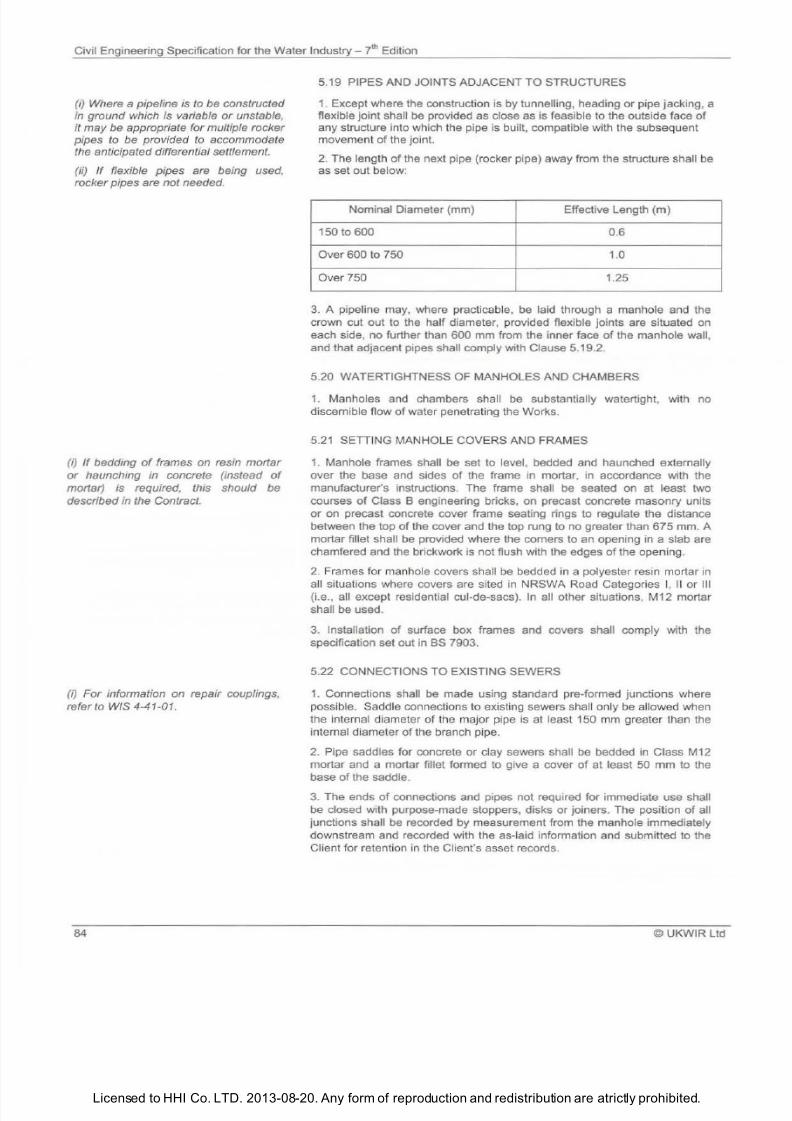
7/21/2019 The Civil Engineering Specification for the Water Industry 7th
http://slidepdf.com/reader/full/the-civil-engineering-specification-for-the-water-industry-7th 90/176Licensed to HHI Co. LTD. 2013-08-20. Any form of reproduction and redistribution are atrictly prohibited.
Civil Engineering Specification for the Water Industry 7lh Edition
i)
Where a pipeline is to be constructed
in ground which is variable
or
unstable,
it may be appropriate for multiple rocker
pipes to be provided to accommodate
the anticipated differential settlement.
ii)
If
flexible pipes are being used,
rocker pipes are not needed.
ij
If
bedding of frames on resin morlar
or
haunching in concrete instead
of
morlar) is required, this should be
described in the Contract.
i)
or
information on repair couplings,
refer to WIS 4-41-01.
8
5.19 PIPES AND JOINTS ADJACENT TO STRUCTURES
1
Except where the construction is
by
tunnelling, heading or pipe jacking, a
flexible joint shall
be
provided as close as is feasible to the outside face
of
any structure into which the pipe is built, compatible with the subsequent
movement of the joint.
2 The length
of the
next pipe (rocker pipe) away from the structure shall
be
as set out below:
Nominal Diameter (mm) Effective Length (m)
150 to 600
0.6
Over 600 to 750
1.0
Over 750 1.25
3
A pipeline may, where practicable, be laid through a manhole and the
crown cut out to the half diameter, provided flexible joints are situated on
each side, no further than 600 mm from the inner face of the manhole wall,
and that adjacent pipes shall comply with Clause 5.19.2.
5.20 WATERTIGHTNESS OF MANHOLES AND CHAMBERS
1 Manholes and chambers shall
be
substantially watertight, with no
discernible flow of water penetrating the Works.
5 21
SETTI
NG
MANHOLE COVERS AND FRAMES
1 Manhole frames shall be set to level, bedded and haunched externally
over the base
and
sides
of
the frame
in
mortar,
in
accordance with the
manufacturer s instructions. The frame shall be seated on at least two
courses of Class 8 engineering bricks, on precast concrete masonry units
or on precast concrete cover frame seating rings to regulate the distance
between the top
of the
cover and the top rung to no greater than 675 mm. A
mortar fillet shall
be
provided where the corners to an opening in a slab are
chamfered and the brickwork is not flush with the edges of the opening.
2 Frames for manhole covers shall
be
bedded in a polyester resin mortar in
all situations where covers are sited in NRSWA Road Categories I, II or Ill
(i.e., all except residential cui-de-sacs). In all other situations. M12 mortar
shall be used.
3 Installation
of
surface box frames and covers shall comply with the
specification set out in BS 7903.
5.22 CONNECTIONS TO EXISTING SEWERS
1 Connections shall be made using standard pre-formed junctions where
possible. Saddle connections to existing sewers sha ll only be allowed when
the internal diameter of the ma jor pipe is at least 150 mm greater than the
internal diameter
of
the branch pipe.
2
Pipe saddles for concrete or clay sewers shall be bedded in Class M12
mortar and a mortar fillet formed to give a cover
of
at least 50 mm to the
base
of
the saddle.
3
The ends
of
connections and pipes not required for immediate use shall
be closed with purpose-made stoppers. disks or joiners. The posi t ion of all
junctions shall be recorded by measurement from the manhole immediately
downstream and recorded with the as-laid informati
on
and submitted to the
Client for retention in
the
Client s asset records.
©UKWIR Ltd
7/21/2019 The Civil Engineering Specification for the Water Industry 7th
http://slidepdf.com/reader/full/the-civil-engineering-specification-for-the-water-industry-7th 91/176Licensed to HHI Co. LTD. 2013-08-20. Any form of reproduction and redistribution are atrictly prohibited.
Civil Engineering Specification for the Water
Industry
J h
Edition
i) The material required for filling should
be described in the Contract.
ii) Any requirement for clearing sewers
prior to filling should be described in the
Contract.
i)
Marker and indicator posts should be
sufficient to allow the location
of
the
water mains to be easily identified.
i) Any requirements for more stringent
tolerances should be described in the
Contract.
ii) Where a pipeline is to be constructed
in ground
wh
ich is variable or unstable,
it may
e
appropriate for a larger
tolerance for line and level to be
described
in
the Contract.
i) Clauses 2.34 and 2.91 cover
materials for drawcords and cable
ducting, respectively.
© UKWIR l td
5.23 SEWERS AND MANHOLES TO BE ABANDONED
1 Where sewers are to be abandoned and filled by grouting, the lowest
point of the abandoned length shall be suitably sealed, and the filling
operation shall commence from that point and continue progressively so as
to fill all voids completely.
2
The shafts
of
manholes
on
abandoned sewers shall be broken down to a
level
1
m below finished ground level and the remaining void filled as
described in the Contract.
5.24 JUNCTIONS AND LATERALS ON SEWERS
1 Junctions and laterals shall be effectively sealed with an end cap, the
location of which shall
be
positively
indicated
2
End caps on junctions and laterals shall be secured by sta kes and
concrete. Marker tape sha ll be laid between the location peg and end cap
of
the
lateral.
3
Records
of
depth and location
of
junctions at the sealed ends
of
laterals
shall be recorded and a copy of the record provided to the Client as work
proceeds.
5.25 MARKER AND INDICATOR POSTS
1 Marker and indicator posts shall be erected to show the location
of
valves
and other fittings, changes of direction and at field boundaries.
2
Permanent ground markers shall be constructed at locations shown. A
schedule
of
co-ordinates
of
the ground markers shall be supplied with the
as-laid records and submitted to the Client for retention in
the Client s asset
records.
3
Marker posts shall be placed at field boundaries and
in
open country, and
shall be at intervals of not more than one kilometre .
4
Installation
of
indicator plates shall comply with the specification set out in
BS 7903.
5.26 TOLERANCES FOR PIPELINES
1. The line and level
of any pipeline shall not deviate from that described in
the
Contract by more than 20
mm
and any combination
of
such deviations
shall not create a reverse gradient.
5.27 CABLE DUCTS
1
The requirements
of
WIMES 3.02 shall
be
followed.
2
Cable ducts shall be laid with a 75 mm bed and surround of sand.
3. All ducts terminating in buildings shall extend 150 mm above slab level.
5.28 INSTALLATION OF VALVES
1 During installation, valves shall be kept in the closed position.
2 Extension spindles shall
be
accurately Installed to hold the spindle
in
alignment without binding. All
va
lves shall be set
so
that the normal position
of
the operating spindles is perpendicular to the line
of
the main.
85
7/21/2019 The Civil Engineering Specification for the Water Industry 7th
http://slidepdf.com/reader/full/the-civil-engineering-specification-for-the-water-industry-7th 92/176Licensed to HHI Co. LTD. 2013-08-20. Any form of reproduction and redistribution are atrictly prohibited.
Civil Engineering Specification for the Water Industry
?
hEdition
i) For provisions relating to pollution
o
watercourses, see Clause 1.15 .
i)
Horizontal Directional Drilling Good
Practices Guidelines :fd Edition) is
available from the North American
Society for Trenchless Technology
(NASTT) (There is no guidance
available
in
the
UK).
ii) Other drillinglmoling techniques are
available.
I)
The arrangements for the
maintenance and removal
o
temporary
water supply mains should be detailed in
the Contract.
(ii) Where temporary water supplies are
required to cross highways and roads,
prior approval may be required from the
relevant Highway Authority.
Arrangements for the protection o hese
temporary mains should be detailed in
the Contract.
86
3. After installation, any damage to corrosion protection coatings shall be
made good, in-line with Clause 5.14. Valves shall be tested to their full
extent to ensure their correct operation.
4 To avoid the necessity for man entry into any chamber for valve
opening/closing, an extension spindle shall be used.
5 Air valves shall be installed in drained chambers, where practical, and
where this is not, they shall be installed either with their air vent(s) at a level
higher than that to which water could rise or in sealed chambers.
6
Air valves shall be installed with an isolating valve between the
branch/tapping off the main and themselves, to facilitate their maintenance
without interruption to the mains supply.
7
Installation of fire hydrants shall comply with the specification set out
in
BS 9990.
5.29 WASHOUTS
1. The washout layout shall ensure the safe disposal
of
the contents
discharged and shall not pollute any ditch , watercourse, highway drain or
surface water sewer.
2. To avoid the necessity for man entry into any chamber for operation, an
extension spindle shall be used.
3. Installation of underground washouts shall comply with the specification
set out in
BS
7903.
5.30 ALTERNATIVE PI
PE
INSTALLATION TECHNIQUES
1. Pipe splitting (mains bursting) shall be carried out
in
accordance with
Damage Control Procedures for Pipeline Construction Involving Pipe
Splitting issued jointly by British Gas (currently Transco) and UKWIR.
2. Directional drilling shall be undertaken in one continuous operation.
3.
The drill/mole shall be fitted with a signal generator to assist in locating
the end and the route of the drill
5.31 CONNECTIONS TO EXISTING WATER SUPPLY PRIESSURE
PIPELINES
1.
The dimensions of the existing pipe at the point of connection shall be
checked to ensure the compatibility of the proposed connection fittings.
5.32 TEMPORARY WATER SUPPLY MAINS
1.
The sizes, materials and locations of all temporary mains shall be agreed
with the Client, prior to commencement. All temporary mains shall be
suitable for the working pressure in the area.
2. Temporary mains shall be set up, disinfected and sampl
ed,
as specified
by the Client. The relevant connections shall be made and supply restored
within a period agreed with the Client.
3. The Contractor shall ensure that all temporary hoses and temporary
mains are kept free from ice and are fully operational during cold weather.
©UKWIR
Ltd
7/21/2019 The Civil Engineering Specification for the Water Industry 7th
http://slidepdf.com/reader/full/the-civil-engineering-specification-for-the-water-industry-7th 93/176Licensed to HHI Co. LTD. 2013-08-20. Any form of reproduction and redistribution are atrictly prohibited.
Civil Engineering Specification for the Water ndustry 7l Edition
(i) A regulatory position statement
Leaving Decommissioned Asbestos
Pipes in Excavations and gwdance
notes
re
available from the
Environment Agency.
(ii) he fill material should be detailed in
the Contract.
© UKWIR Ltd
5.33 WATER MAINS TO
BE
ABANDONED
1 Where water mains or services are abandoned, they shall be physically
severed from the network. A closed gate valve sha
ll
not be used to achieve
disconnection
2 Where water mains are
to
be abandoned and filled by grouting , the
lowest point of the abandoned length shall be suitably sealed, and the filling
operation shall commence from that point and continue progressively so as
to fill all voids completely.
3 All abandoned mains shall be identified and recorded with the as-laid
information and submitted to the Client for retention
in
the Client s asset
records.
4
Asbestos cement mains, where decommissioned , shall be recorded with
the as-laid information and submitted to the Client for retention in the
Client s asset records. Where an asbestos
ma
in has been burst and
asbestos shards remain
in
the ground, this shall be recorded with
the
as
laid information and submitted to the Client for retention in the Client s asset
records.
8

7/21/2019 The Civil Engineering Specification for the Water Industry 7th
http://slidepdf.com/reader/full/the-civil-engineering-specification-for-the-water-industry-7th 94/176Licensed to HHI Co. LTD. 2013-08-20. Any form of reproduction and redistribution are atrictly prohibited.
ivil Engineering Specification for the Water
Industry i h
Edition
©UKWIR
Ltd
7/21/2019 The Civil Engineering Specification for the Water Industry 7th
http://slidepdf.com/reader/full/the-civil-engineering-specification-for-the-water-industry-7th 95/176Licensed to HHI Co. LTD. 2013-08-20. Any form of reproduction and redistribution are atrictly prohibited.
Civil Engineering Specification for the Water
Industry
th Edition
The Notes for Guidance are not part of
the Specification.
i)
This Section is intended only for
small-scale masonry buildings and basic
steel framed and clad enclosures on
operational
sites.
Where design
is
included in
the
Contract, all buildings
which are occasionally occupied and/or
heated should, as a minimum, comply
with the Building Regulations 2000.
i)
Any requirement for rendering of
manholes and chambers should be
described in the Contract.
ii) The bond should be described in the
Contract.
iii) The required
class of
mortar and
type of cement should be described in
the Contract see Clause 2.82) .
iv) For guidance on the design
of
oints
and jointing in building construction, see
BS 6093.
i)
The
type
of
jointing and pointing
should be described in the Contract.
ii) ny requirement for sample panels
and their approval should be described
in the Contract.
i)
Where
the
filling or semi-filling
of
cavities with insulating material
is
required, it should be described in the
Contract.
© UKWIR Ltd
SECTION
BUILDING WORKS
6.1
BRICKWORK AND BLOCKWORK GENERALLY
1. Brickwork and blockwork shall comply with the relevant provisions of BS
EN 1996
2.
2.
The moisture content
of
the bricks shall be adjusted so that excessive
suction is not exerted on the mortar.
3.
Bricks in each course shall break joint correctly with the bricks
underneath. The courses shall be laid parallel with joints
of
uniform
thickness and shall be kept straight or regularly curved as required.
Brickwork shall be gauged to rise 300 mm
in
four courses. Vertical joints
shall
be
in alignment as required by the bond and shall have an average
thickness
of
10 mm. Bricks forming reveals and internal and external angles
shall be selected for squareness and built plumb. Bricks with single frogs
shall
be
laid frog upwards.
4
Brickwork and blockwork shall rise uniformly; corners and other advanced
work shall be raked back and not raised above the general level more than
1 m. No brickwork shall
be
carried up higher than 1.5 m in one day. No bats
or broken bricks shall be incorporated in the work unless essential for bond.
Where cut blocks are required all cutting shall be carried out with a
mechanical cutting disk.
5 Completed brickwork and blockwork shall be protected
at
all times from
scaffold splash mortar droppings grout leakage from suspended slabs and
the
harmful effects
of
weather. Brickwork and blockwork sha ll
be
allowed to
set thoroughly hard before cutting or chasing is carried out.
6. Blocks used in fair faced blockwork shall have a smooth undamaged face
and be neatly pointed with flush joints .
6.2 BRICKWORK AND BLOCKWORK JOINTING AND POINTING
1.
Bricks and blocks shall be laid in mortar properly bedded and jointed
and all joints filled with mortar at every course.
2.
Where the surface of walling does not provide
an
adequate key the joints
on faces
of
walls to
be
plastered shall be raked out 12
mm
deep.
6.3
CAVITY WALLS
1. Cavity wa lls shall have a minimium cavity width
of
50 mm and a minimal
air gap of 25 mm between any cavity insulati
on
and the outer skin. Cavity
walls shall
be bu
il t with wall ties
un
iformly spaced 450
mm
apart vertically
and 750 mm apart horizontall
y
staggered and laid to fall outwards.
Additional ties sha ll be used near the sides of all openings one for each
third course
of
bricks. Care shall be taken to keep the ties within the cavity
free from mortar or mortar droppings and any mortar or debris collecting at
89
7/21/2019 The Civil Engineering Specification for the Water Industry 7th
http://slidepdf.com/reader/full/the-civil-engineering-specification-for-the-water-industry-7th 96/176Licensed to HHI Co. LTD. 2013-08-20. Any form of reproduction and redistribution are atrictly prohibited.
Civil Engineering Specification for the Water Industry yth Edition
i) Larger-scale underpinning should be
described in the Contract and may
require the services of a specialist
contractor.
i) The type of scrim material should be
described in the Contract.
ii) f joints are to be cut or covered
as
an alternative to scrim, this should be
described in the Contract.
90
the bottom of the cavity shall be cleaned out through temporary openings
left for this purpose in the bottom courses.
2. Weepholes shall be provided by leaving open perpendicular joints at
intervals not greater than 900 mm in the course immediately above the
cavity tray. Where the cavity tray does not ex tend the full length of the
exposed wall, i.e., at an opening and stop end, at least two weep holes, not
more than 450 mm apart, shall be provided.
6.4 DAMP-PROOF COURSES
1. Construction
of
damp-proof courses shall comply with the relevant
provisions
of
BS EN 1996-2, BS 6576, BS 8102 and BS 8215.
6.5 CORBELLING
1. Oversa
il
corbelling shall not exceed 30 mm
on
each course.
6.6 BONDING TO CONCRETE
1. Where brickwork
or
blockwork is to be bonded to concrete, this shall be
achieved by means
of
metal ties evenly placed
at
three per square metre.
Brickwork and blockwork shall be brought up subsequent to the concrete.
6.7 UNDERPINNING
1. Underpinning in brickwork shall be carried up
to
within one course
of
the
underside
of
the existing structure and allowed to set. The remaining course
shall be bedded in mortar and wedged tightly against the existing structure
with slate pieces.
6.8 CENTERING AND LAGGING
1. Centering and lagging used for the construction of brickwork and
blockwork shall remain in place for such time as is necessary for the
brickwork and blockwork to develop sufficient strength to prevent sagging or
cracking of joints.
6.9 BRICKLAYING AND BLOCKLAYING IN COLD WEATHER
1. Materials used in bricklaying and blocklaying shall be frost free and no
bricks
or
blocks shall be laid when the ambient temperature is
be
low 3•c
unless special precautions are taken. Any additives used in the mortar shall
not cause a variation in the colour of the joints. Completed work shall be
protected adequately during cold weather.
2. General working practices shall be in accordance with the Brick
Development Association publication Bricklaying in Winter Conditions .
6.10 PREPARATION FOR PLASTERING
1. Unless a bonding agent is used, concrete ceilings, ceiling beams,
columns and stanchions sha
ll
be dubbed out, as necessary, before
plastering is commenced and the mix used for dubbing shall be similar to
that used for first undercoating. The surface of in-situ concrete shall be
cleaned
of
dust, loose particles and other matter. Surfaces shall
be
wetted
immediately before plastering is commenced.
2. Angles between walls and ceilings, vertical angles and joints between
dissimilar solid backgrounds, shall be reinforced with 90 mm wide scrim set
in plaster and trowelled flat. All joints between plasterboards shall be
similarly treated.
3. Expanded metal angle beads shall be provided
at
a
ll
external corners.
©UKWIR Ltd
7/21/2019 The Civil Engineering Specification for the Water Industry 7th
http://slidepdf.com/reader/full/the-civil-engineering-specification-for-the-water-industry-7th 97/176Licensed to HHI Co. LTD. 2013-08-20. Any form of reproduction and redistribution are atrictly prohibited.
Civil Eng ineering Specification for the Water Industry - 7l Edition
i) The type
o
finish from as 8204 2 and
as
8204 4 should be described in the
Contract.
© UKWIR Ltd
6 11 FIXING OF PLASTERBOARD
1
Drylining shall comply with BS 8212. Plasterboard for ceilings shall be
fixed to
the
support
t
150
mm
centres with plasterboard nails, and fastened
so that the joints are staggered. Noggins or other fixing surface shall be
provided, as necessary, to ensure that edges of plasterboard are secured
adequately. Ends
of
sheets shall
be
butted tightly and edges left with a gap
not exceeding 5 mm.
2
Where sheeting has been cut, nails shall not be less than 18 mm from cut
edges. Nails shall be driven well home, with heads slightly below the
surface, but shall not break the paper.
6.12 PLASTERING
1 Plastering sha
ll
norma
ll
y be applied in two coats, in accordance with th e
manufacturer s instructions, and batches shall
be
used as soon as possible
after water has been added. The total thickness of both coats shall be of
the
order
of
, but shall not exceed,
13
mm.
2 Where three coat work is described in the Contract , the thickness shall be
of
the order
of
, but shall not normally exceed, 18 mm.
3
The thickness of two coat work applied to concrete ceilings and soffits
or
plasterboard shall not exceed
9
mm.
4 The thickness
of
finishing coats shall be
of
the order
of
3 mm, except
where board finished plaster is used when the th ickness sha ll be 5 mm and
comply with the relevant provisions of PO CEN/TR 15123, BS EN 13914-2
and BS 8481.
5 Expanded metal beads, or similar, shall be provided at all arrises.
6.13 PLASTERING
IN
COLD WEATHER
1 When the ambient temperature is soc
or
less, the portion
of
the Works to
be plastered shall be completely enclosed. The ambient temperature shall
be raised and maintained above
s·
until the completion of plastering and
hydration.
6.14 CONCRETE FLOOR FINISHES
1
Concrete floor finishes shall comply with the relevant provisions
of BS
8204-2 and BS 8204-4.
2 Minimum thickness of sand/cement floor screeds shall be 35 mm when
laid directly on a prepared concrete slab or 75 mm when separated from the
slab
by
a membrane.
3
Structural concrete slabs shall be suitably treated to provide a full bond
prior to screeding, unless a membrane is to
be
used.
4
Screeds laid in wash down areas shall be laid to a minimum fall
of 1
in
40.
6.15 FLOOR T
ILI
NG
1 Floor tiling shall comply with the relevant provisions of BS 5385-3 and BS
5385-5 for rigid tiling and
BS
8203 for flexible tiling.
6.16 TERRAZZO FLOOR FINISHES
1
Terrazzo floor finishes shall comply with the relevant provisions
of BS
8204-4.
91
7/21/2019 The Civil Engineering Specification for the Water Industry 7th
http://slidepdf.com/reader/full/the-civil-engineering-specification-for-the-water-industry-7th 98/176Licensed to HHI Co. LTD. 2013-08-20. Any form of reproduction and redistribution are atrictly prohibited.
Civil Engineering Specification for the Water Industry 7
h
Edition
i)
This clause
is
intended to apply to
basic structural steel framed buildings,
used
to
enclose process equipment.
(ii) Any particular design requirements or
architectural finishes should be
described in the Contract.
(iii) Where steelwork is to be galvanised.
it should be described in the Contract,
unless covered
y
Clause 6.20.3.
(iv) Other protective coatings, if
required, should be described in the
Contract.
v)
Requirements for the testing of welds
should be described in the Contract.
(vi) Structural steelwork should comply
with the National Structural Steelwork
Specification for Building Construction
published by the British Constructional
Steelwork Association.
vii) The
Contract should state the
arrangements for sampling and testing
ofall surface treatment materials.
92
6.17 EXTERNAL RENDERING
1 External rendering shall comply with
BS EN
13914-1 and shall be applied
to a total th ickness of not less than
2 mm.
The
mix
for both coats shall be
as for Class M2 mortar. The first coat shall be applied levelled scratched
and left to dry for not less than 3 days
in
warm weather and not less than 7
days
in
cold or wet weather. The suction of the surface of the first coat shall
be adjusted as necessary by wetting before applying the second coat
which shall be coloured as directed levelled and lightly trowelled with a
wooden trowel.
6.18 WALL TILING
1. Wall tiling shall comply with the relevant provisions of
BS
5385-1 BS
5385-2
and
BS 5385-4.
6.19
CARPENTRY AND JOINERY
1. Wherever possible cutting and shaping of all timber shall be completed
before preservative treatment is carried out. Where any cutting or shaping
has to be carried out after treatment the cut or worked surfaces shall be
given two coats of the preservative. After treatment timber shall be
thoroughly dried out before use.
2. The whole of the joinery shall be cut and framed together as soon as
possible after the commencement of the work. Workmanship shall comply
with the relevant provisions of BS
1186-2
and BS
6446.
Except where work
is described in the Contract as being to finished sizes,
3
mm shall be
allowed for each wrot face. Frames casings and other joinery fittings
sha
ll
be secured to hardwood fi
slips built in for the purpose. Where
hardwood fixing slips have not been provided receiving surfaces shall be
plugged with hardwood plugs or other suitable type plugs.
3. Manufactured un i
ts
to be painted shall be primed at the place of
manufacture.
6.20 STRUCTURAL STEELWORK
1.
Built
in
joists used in masonry structures shall be cut to length by cold
sawing. The minimum bearing length on masonry shall be 1
mm,
and
minimum crushing strength of supporting blockwork shall be 7 N/mm
2
or a
padstone provided to spread the load.
2. Structural steelwork for steel framed buildings shall be designed
detailed fabricated and erected in accordance with BS EN 1993-1 and BS
EN 1090-2.
3. All structural steelwork
in
buildings housing wet processes or otherwise
prone to condensation shall be galvanised to BS
EN
ISO 1461 with a coat
thickness of
85
IJm
.
4. Welders employed
in the
fabrication of steelwork shall be certified to BS
EN 287-1 for tests appropriate to the work to be undertaken.
5. Steelwork to be embedded
in
concrete shall have any loose mill scale
and rust removed.
6. As a minimum all steelwork to
be coated sha ll be blast cleaned to
second quality then treated with two coats of quick drying primer reference
shall be made to BS 7079. All surface treatment shall comply with the
relevant provisions of BS EN ISO
12944
and shall be completed as far as
practicable before steelwork is delivered to Site. Sampling and testing of all
surface treatment materials
sha
ll be
in
accordance with the Contract.
7.
All steelwo rk fastenings shall receive protective treatment
to
at least
as
good a standard as the parts connected.
©UKWIR
Ltd
7/21/2019 The Civil Engineering Specification for the Water Industry 7th
http://slidepdf.com/reader/full/the-civil-engineering-specification-for-the-water-industry-7th 99/176Licensed to HHI Co. LTD. 2013-08-20. Any form of reproduction and redistribution are atrictly prohibited.
Civil Engineering Specification for the Water
Industry
7lh Edition
i)
Thickness of loor boarding should be
described in the Contract.
ii) f chipboard s to be used instead of
floor boarding, this should be described
in the Contract.
i)
Security requirements for windows
and
doors should be stated in the
Contract.
i) BS EN 927-1 gives guidance on
exteriorpaint protection
systems.
ii) Refer to Clause 2.88 for paintwork on
buildings.
i) The types and siz s
of
slate and tiles,
together with details
of
any laps,
battens, fixings, beddings, underfelt and
boarding. should be described in
the
Contract.
©
UKWIR Ltd
8 After tig htening, all bolts shall have at least two threads projecting beyond
the nut or lock nut. Bolt shank length shall be such as to ensure at least one
thread
sha
ll rema in clear between
the nu
t
and
the shank.
9
When required, the following tests
of
butt welds shall be made;
(a) Ultrasonic examination to BS EN 1714;
(b) Penetration test to BS EN 571-1; or
(c) Magnetic particle test to
BS EN
ISO 9934-1
1
0
Erection tolerances for build ings containing an overhead gantry crane
should comply with the requirements
of
Appendix Fin
BS
466:1984.
6 21
ROOFS
1 Roof members shall be fabricated in accordance with BS EN 1995-1-1.
2 Flats and gutters shall be covered with BS EN 636-3G plywood or
tongued and grooved wrot boarding laid diagonally, firred to falls of not less
than 1 in 120 for lead and copper and 1 in 60 for bitumen felt.
6.22 TIMBER FLOORS
1
Floor joists shall
be
either built into brickwork or blockwork, or held in
galvanised steel joist hangers, and sha ll be trimmed, as described
in
the
Contract. Bridging shall
be
spaced at every 1.8 m apart and shall be 50
mm
thick to the full depth
of
the joists, or 38
mm
by 50 mm herringbone strutting.
2 Boarding shall be cramped up and nailed with cut flooring nails. Trimmed
openings shall have mitred borders 75 mm in width.
6.23 DOOR FRAMES
1 Door frames shall be fitted into prepared openings, drilled and p lu gged at
three points per jamb. Fixings shall be suitable for the proposed application
and be not more than 600 mm apart and not more than 150 mm from top or
bottom. The door frame shall
be
bedded in non-shrink or epoxy grout.
2 The joint between external door frames and adjacent walls shall be
continuously pointed with gun-applied butyl or other approved non-setting
mastic.
6.24 WINDOWS
1
Window frames shall
be
securely fixed to openings, in accordance with
manufacturer s instructions, and shall be continuously pointed with gun
applied butyl or other suitable non-setting mastic.
6.25 GLAZING
1 Glazing shall comply with the relevant provisions
of
BS 6262.
6.26 PAINTING
1
Painting
of
structural steelwork shall comply with the relevant provisions
of BS
EN ISO 12944. Other painting shall comply with the relevant
provisions
of BS
6150.
6.27 SLATING AND TILING
1 Slating and tiling work shall comply with the relevant provisions
of
BS
5534.
93
7/21/2019 The Civil Engineering Specification for the Water Industry 7th
http://slidepdf.com/reader/full/the-civil-engineering-specification-for-the-water-industry-7th 100/176Licensed to HHI Co. LTD. 2013-08-20. Any form of reproduction and redistribution are atrictly prohibited.
Civil Engineering Specification for the Water Industry - ?
tt
Edition
i) A written guarantee may be available
for asphalt work incorporating terms
currently applied by the Mastic Asphalt
Council and Employers Federation.
i) Th e surface finish should be
described in the Contract.
i)
Where heating and hot water
systems
are to be installed, reference should be
made to BS EN 12828, BS EN 12831
and BS EN 14336.
(ii) Reference should be made to the
Water Supply (Water Fittings)
Regulations 1999, the Water Supply
(Water Fittings) Regulations (Northern
Ireland) 2009
or
the Scottish Water
Byelaws 2004.
i) The
colour
o
profiled steel may
require the approval
o
the Local
Planning Authority.
94
6.28 LIGHTWEIGHT CONCRETE ROOF SCREEDS
1. Lightweight concrete roof screeds shall be laid to the necessary fa ll
s and
shall comply with the relevant provisions
of
BS 8217. Before any felt is laid ,
a coat of bitumen primer shall be applied and allowed to dry.
6.29 ASPHALT ROOFING
1. Mas
ti
c asphal t shall be laid in accordance with the relevant provisions of
BS 8218 on an underlay
of
sheathing felt laid loose and with join
ts
lapped
at least 50 mm. The roof shall be set out with properly formed high points,
water lines and mitred bays, where required.
6.30 BITUMEN FELT ROOFING
1. Built-up bitumen felt roof coverings sha ll be laid in accordance with the
relevant provisions of BS 8
21 7.
6.31 PLUMBING
1. Plumbing for domestic water supply shall comply with the relevant
provisions of BS 6700, BS EN 806-2 and BS EN 806-4.
6.32 OPEN INGS IN W LLS, FLOORS AND CEI
LI
NGS
1. Box outs and/
or
cut openings through walls, floors and ceilings for the
passage
of
pipes and cables shall be provided. Where described in the
Contract, tube sleeves cut off flush with the finished surface shall be
provided and fixed in position. All openings and ducts sha ll be sealed on
completion to prevent the passage
of
liquids, or toxic
or
explosive gases.
6.33 TOLERANCES FOR BUILDING WORKS
1. Tolerances for building works, except where otherwise described in the
Contract, shall not exceed the permissible deviations from levels and
dimensions given in BS 5606, where applicable, for the corresponding types
of work.
6.34 ELECTRICAL INSTALLATIONS
1. All electrical installations shall comply with the Requirements for
Electrical Installations , BS 7671 published by the Institution of Electrical
Engineers.
6.35 PROFILED STEEL CLADDING
1. Profiled steel roof cladd ing shall be designed in accordance with BS
EN
1993-1-3. In addition, the combination of purlin spacing and sheeting profile
shall be of adequate stiffness to prevent undue deflection (such
as
to cause
loss of balance) when walked on during erection and maintenance.
2. Sheets shall be supplied to Site, cut to the required length. Any incidental
Si
te
cuts shall be sealed in accordance wi
th
the manufacturer s instructions,
using matching materials.
3. Any cladding sheets with damage to the external protective coating shall
be rejected. Other damage shall be repaired as in Clause 6.35.2. Sheeting
shall be carefully stacked on Site with its dust wrap in place , until required.
©UKWIR
l td
7/21/2019 The Civil Engineering Specification for the Water Industry 7th
http://slidepdf.com/reader/full/the-civil-engineering-specification-for-the-water-industry-7th 101/176Licensed to HHI Co. LTD. 2013-08-20. Any form of reproduction and redistribution are atrictly prohibited.
Civil Eng ineering Specification for the Water Industry
?
hEdition
i) These clauses are a guide for the use
o
beam and blockn or pre-stressed
concrete planks up to 5 m span.
© UKWIR Ltd
4. Flashings and fillers shall be purpose-made to suit the profile
of
the
sheets being used.
6.36 PRECAST CONCRETE FLOORS
1. Units shall be delivered cu t to the correct lengths and complete with any
service openings required. Any Site modifications shall be carefully cut in
accordance with manufacturer s instructions, following specific permission
from the manufacturer in each case.
2.
Any unit with handling damage to the bearing area shall be rejected.
3. Minimum bearing areas for precast units bearing on steelwork shall be as
laid down
by
the manufacturer. No negative tolerance shall
be
allowed on
these dimensions. Units bearing on masonry shall have a minimum bearing
length
of
100 mm and the strength
of
the masonry shall
be
as specified by
the designer, but not less than 7 N/mm
2
·
4. In-situ structural topping shall
be
cast in
the
sequence laid down by the
Designer. Propping requirements shall be exactly followed and props left in
place until the specified strength is reached.
5. Bricks, blocks and other materials shall not be stored on the floor.
6.
Units with excessive pre-camber resulting in differential levels between
planks exceeding 10 mm shall be rejected. Screeded floor finishes shall be
to the tolerances laid down
in
Clause 4.25.
6.37 COMPOSITE FLOORS
1. In-situ concrete floors utilising permanent steel soffit formwork as part
of
a composite structural construction, shall not
be
used in buildings housing
wet processes or otherwise subject to condensation.
2. The exposed soffit
of
any such permanent formwork used shall
be
protected to the same standard as the general structural steelwork.
9
7/21/2019 The Civil Engineering Specification for the Water Industry 7th
http://slidepdf.com/reader/full/the-civil-engineering-specification-for-the-water-industry-7th 102/176Licensed to HHI Co. LTD. 2013-08-20. Any form of reproduction and redistribution are atrictly prohibited.
ivilEngineering Specification for the Water ndustry l Edition
9
UKWIR Ltd
7/21/2019 The Civil Engineering Specification for the Water Industry 7th
http://slidepdf.com/reader/full/the-civil-engineering-specification-for-the-water-industry-7th 103/176Licensed to HHI Co. LTD. 2013-08-20. Any form of reproduction and redistribution are atrictly prohibited.
Civil Engineering Specification for
the
Water Industry yth Edition
The
Notes for Guidance are not part of
the Specification.
i) The Contract should describe
requirements for:
a) temporary pipework, its connection
to existing mains and associated testing
apparatus;
b) disinfection, chemical and
bacteriological sampling, and the test
parameter values to be achieved; and
(c) samples and/or frequency of testing
of materials.
(ii) Refer to Guidance Note 2 of the
Water UK Principles of Water Supply
Hygiene for guidance on the hygienic
transport and storage
of
new potable
water pipes.
(iii) Where water fittings and appliances
are to be used to convey water derived
from the public water supply, which
brings them under the scope of the
Water Supply (Water Fittings)
Regulations 1999, the Water Supply
(Water Fittings) Regulations (Northern
Ireland)
2 9
or Scottish Water Byelaws
2004,
pressure testing should be
undertaken in accordance with these
regulations.
i) The pipeline cleaning system should
be appropriate for the pipe material and
should be described in the Contract.
(ii) The Contract should describe the
type of swabs and the number
of
passes.
i) See
also Clauses
5
1 and
5 6.
©UKW IR Ltd
SECTION
TESTING AND DISINFECTION
7 1 CLEANSING AND SWABBING OF PIPELINES
1
On completion of construction and before any disinfection internal
surfaces
of
pipelines shall be cleaned thoroughly.
2 On completion of the hydrau lic test on water
ma
ins a foam swab shall be
passed through the
ma
in a sufficient number of times to achieve clear wash
water.
3
All swabs shall
be
recovered and accounted for after mains cleaning.
7.2 PRECAUT
ION
S PRIOR TO TESTING PIPELINES
1
Before testing any pipeline it shall
be
anchored adequately and thrusts
from bends branch outlets or from the pipeline ends shall be transmitted to
solid ground or to a suitable temporary anchorage.
2
Open ends shall
be
stopped with plugs caps or blank flanges properly
jointed.
3
Testing against closed valves shall not be permitted.
7.3 TESTING METHOD PROGRAMME AND NOTIFICATION
1
The proposed programme and method
of
testing and swabbing sha
ll
be
stated in the Contract.
2
The Client sha ll
be
notified of the intenti
on
to test a section of pipeli
ne
within the period specified in the Contract.
97
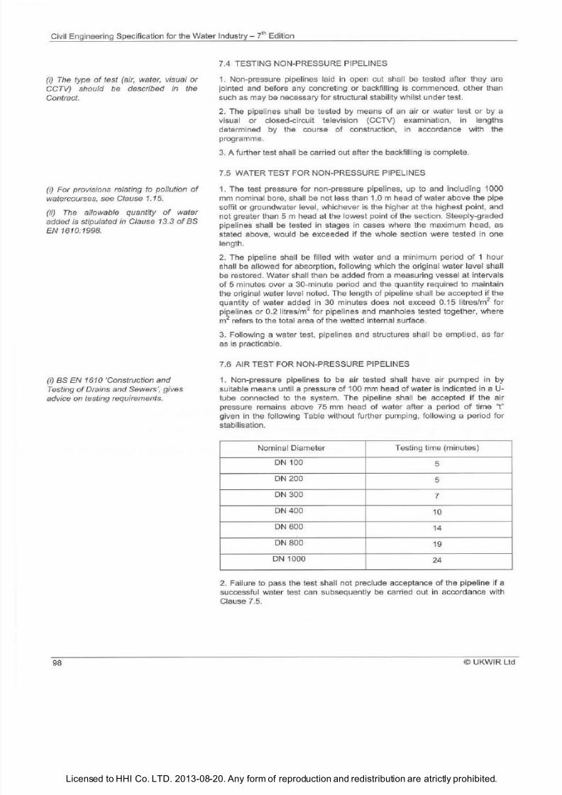
7/21/2019 The Civil Engineering Specification for the Water Industry 7th
http://slidepdf.com/reader/full/the-civil-engineering-specification-for-the-water-industry-7th 104/176Licensed to HHI Co. LTD. 2013-08-20. Any form of reproduction and redistribution are atrictly prohibited.
Civil Engineering Specification for the Water
Industry
ih Edition
i)
The type of test (air, water, visual or
CCTV) should e described in the
Contract.
(i) For provisions relating to pollution of
watercourses, see Clause
1.
15 .
ii)
The allowable quantity of water
added is stipulated in Clause 13.3 of as
EN 1610:1998.
(i)
as
EN 1610 Construction and
Testing of Drains and Sewers , gives
advice on testing requirements.
98
7.4 TESTING NON-PRESSURE PIPELINES
1 Non-pressure pipelines laid
in
open cut shall be tested after they are
jointed and before any concreting or backfilling is commenced, other than
such as may be necessary for structural stabil ity whil
st
under test.
2
The pipelines shall be tested by means
of
an air or water test or by a
visual or closed-circuit television (CCTV) examination,
in
lengths
determined by the course of construction, in accordance with the
programme.
3 A further test sha ll be carried out after the backfilling is complete.
7.5 WATER TEST FOR NON-PRESSURE PIPELINES
1 ihe test pressure for non-pressure pipelines, up to and including 1000
mm nominal bore, shall be not less than 1.0 m head
of
water above the pipe
soffit or groundwater level, whichever is the higher at the highest point, and
not greater than
5
m head at the lowest point
of
the section. Steeply-graded
pipelines shall be tested
in
stages in cases where the maximum head, as
stated above, would be exceeded if the whole secti
on
were tested in one
length.
2 The pipeline sha ll be filled with water and a minimum period
of
1 hour
shall
be
allowed for absorption, following which the original water level sha ll
be restored. Water shall then be added from a measuring vessel at intervals
of 5 minutes over a 30-minute period and the quantity required to maintain
the original water level noted. The length of pipeline shall be accepted if the
quantity
of
water added in
30
minutes does not exceed 0.15 litres/m
for
pipelines or 0.2 litres/m
for pipelines and manholes tested together, where
m
refers to the total area of the wetted internal surface.
3 Following a water test, pipe
li
nes and structures shall be emptied, as far
as is practicable.
7.6 AIR TEST FOR NON-PRESSURE PIPELINES
1 Non-pressure pipelines to be air tested sha ll have air pumped in by
suitable means until a pressure
of
100 mm head
of
water is indicated in a U
tube connected to the system. The pipeline shall be accepted if the air
pressure remains above 75 mm head of water after a period of time t
given in the following Table without further pumping, following a period for
stabilisation
Nominal Diameter
Testing time (minutes)
DN
100
5
DN 200
5
DN 300
7
DN
400
10
DN
600
14
DN 800
19
DN 1000
24
2
Failure to pass the test shall not preclude acceptance
of
the pipel ine
if
a
successful water test can subsequently be carried out in accordance with
Clause 7.5.
© UKWIR Ltd
7/21/2019 The Civil Engineering Specification for the Water Industry 7th
http://slidepdf.com/reader/full/the-civil-engineering-specification-for-the-water-industry-7th 105/176Licensed to HHI Co. LTD. 2013-08-20. Any form of reproduction and redistribution are atrictly prohibited.
Civil Engineering Specification for the Water Industry - 7
l
Edition
i)
CCTV inspection should be described
in the Contract, if required.
(i) The permissible infiltration is the
same as
the
permissible loss in the
water test in Clause
7.5.
i) BS EN 805 gives the permissible
losses during the
test.
(ii) The Contract should specify either a
water lo
ss
or pressure loss method
of
testing in accordance with BS EN 805.
(iii) Details for
SUe
pressure testing in
accordance with BS EN 805 are
provided
in
IGN 4-01-03 'Field Pressure
Testing
of
Pressure Pipes and Fittings .
(iv) Where a pipeline is to be tested in
sections, the Contract should identify
any constraints in length.
v) The
test pressures should be
described in the Contract.
(vi) Testing should be carried out with
the pipework isolated from the existing
adjacent pipework to prevent the
transmission of thrust.
i) Where a pipeline is to be tested in
sections, the Contract should identify
any constraints in length.
(ii) The test pressures should be
described in the Contract.
(iii) Testing should normally be carried
out
with
the
pipework isolated from the
existing adjacent pipework
to
prevent
the transmission
of
thrust. Howev
er,
this
might not be appropriate where the test
is designed to test the tension capability
of welds and the transfer of thrust
through the pipeline.
© UKWIR Ltd
7.7 CCTV INSPECTION OF PIPELINES
1.
CCTV inspections shall comply with the Model Contract Document f
or
Sewer Condition Inspection 1994, published by The Foundation for Water
Research.
7.8 INFILTRATION
1. Non-pressure pipelines (including tunnels and shafts) and manholes shall
be tested for infiltration after backfilling. All inlets to the system shall be
effectively closed, and any residual flow shall be deemed to
be
infiltration.
2. The pipeline, including manholes, shall be accepted as satisfactory if the
infiltration, including infiltrati
on
into manholes, in 30 minutes does not
exceed 0.2 litres/m
2
where m
2
refers to the total internal surface area
of
the
pipeli
ne
, includi
ng
manholes.
3. Notwithstanding
the
satisfactory completion
of the
above test, if there is
any discernible flow of
water enteri
ng the
pipeline at a point which can be
located either by visual
or
CCTV inspection, then measures as are
necessary to stop such infiltration shall
be
taken.
7.9 TESTING OF DUCTILE IRON, PVC, GRP AND STEEL PRESSURE
PIPELINES
1. The en tire pipeline shall be pressure tested in accordance with
BS EN
805.
2. Gauges used for testing pressure pipelines shall ei ther be of the
conventiona l circu lar type, not less than 200 mm diameter, calibrated in
metres head
of
water,
or
shall have a digital indicat
or
capable of readi
ng
increments
of
0.1 m head. Before any gauge is used, it shall be checked
independently and a dated certificate
of
its accuracy shall be provided.
3.
Before testing, valves shall
be
checked and sealed, the sections
of
main
filled with water and the air released. After having been filled, pipelines shall
be left under normal operating pressure for 24 hours, so as to achieve
conditions as stable as possible for testing.
4. The pressure in the pipeline shall then
be
raised steadily until the
specified test pressure is reached in the lowest part
of
th e sectio
n
and the
pressure shall be
ma
inta ined at this level, by pumping, if necessary, for a
period
of
one hour. The pump shall then be disconnected, and no fu rther
water shall be permitted to enter the pipeline for a further period of one
hour. At the end
of
this period, the original pressure shall be restored by
pumping and the loss measured by drawing off water from the pipeline until
the pressure as at the end of the test is again reached.
5. Where a new pipeline is to connect to an operational pipeline , the final
connection sha ll be inspected visually under normal operating pressure and
there shall be no visible leakage.
7.10 TESTING
O
POLYETHYLENE
PR
ESSURE PIPELINES
1. The testing
of
polyethylene pressure pipelines shall
be
carried out in
accordance with the procedures in IGN 4-01-03 Field Pressure Testing
of
Pressure Pipes and Fittings .
2. Clauses 7.9.2 and 7.9.5 shall apply.
99
7/21/2019 The Civil Engineering Specification for the Water Industry 7th
http://slidepdf.com/reader/full/the-civil-engineering-specification-for-the-water-industry-7th 106/176Licensed to HHI Co. LTD. 2013-08-20. Any form of reproduction and redistribution are atrictly prohibited.
Civil Engineering Specification for the Water Industry - 7 r n Edition
i)
The
Contract should describe the
sampling parameters.
ii) Any specific requirements for
bringing water mains back on line
should be included
in
the Contract.
iii) Timescales for the return o sample
results from bacteriological and
chemical sampling should be described
in the Contract.
iv) Refer to Clause 1.16 for details
relating to water supply hygiene .
i)
The Contract should describe which
o
the two alternative tests s required.
Lagooning is the preferred method but
hosing may be used for smaller
structures.
100
7.11 DISINFECTION OF WATER MAINS
1.
After satisfactory completion of testing and, if applicable, after swabbing,
pipelines intended for conveying potable water shall be disinfected in
accordance with Principles of Water Supply Hygiene and the
accompanying Guidance Notes published by Water UK or as specified in
the Contract.
2. After disinfection and bacteriological and chemical sampling of completed
sections of water mains, no valves shall be turned or any other action taken
which might interfere with the main or existing network without the prior
agreement with the Water Undertaker.
3. On completion of the disinfection, the pipeline shall be left full of water
under operating pressure and with sufficient flow or changes of water so as
to maintain water quality.
4.
Groundwater shall not be a
ll
owed to come into co ntact with the inside of
water mains after disinfection.
7.12 CLEANSING OF STRUCTURES
1. On completion of construction, and before any disinfection, internal
surfaces of structures designed to retain or convey an aqueous liquid shall
be cleaned thoroughly in such a way as to remove all
oil
, grit and other
deleterious matter.
7.13 TESTING OF CONCRETE ROOFS
1. Concrete roofs of structures which are to contain aqueous liquids shall be
watertight and shall, where practicable, be tested prior to the installation of
any waterproof membrane by lagooning with water to a minimum depth of
25 mm for a period of 24 hours.
2. Where it
is
impracticable because of roof falls, or otherwise,
to
contain
25 mm depth of water, the roof shall be thoroughly wetted by continuous
hosing for a period of not less than hours.
3.
In either case, the roof shall be regarded as satisfactory if no leaks or
damp patches show
in
the soffit.
4. The roof covering shall be completed as soon as possible after
satisfactory testing.
7.14 TESTING OF CONCRETE STRUCTURES DESIGNED TO RETAIN
AN AQUEOUS LIQUID
1. After cleaning, and as far as practicable before any earth or other filling is
placed against the outside wall faces, concrete structures designed to retain
an aqueous liquid shall be filled with water at a uniform rate of not greater
than 2 m
in
24 hours. A period
of
up to
21
days sha
ll
be allowed for
stabilisation, after which the water level shall be recorded at 24-hour
intervals, for a test period of 7 days. During the test period the total
permissible drop, after allowing for evaporation and rainfall, shall not exceed
1/500 of the average water depth of the full tank or 10 mm, whichever is the
lesser.
2. If the requirements for the 7-day test are not met then , after completion of
any remedial work, the structure shall be refilled and,
if
necessary, left for a
further stabilisation period after which the water level shall be recorded at
24-hour intervals, for a test period of 7 days.
2. Not withstanding the satisfactory completion of the above test, any
leakage visible on the outside faces of the structure shall be stopped. Any
caulking or making good of cracks in the wa
ll
section shaH where
practicable, be carried out from the inside face.
©UKW R
ltd
7/21/2019 The Civil Engineering Specification for the Water Industry 7th
http://slidepdf.com/reader/full/the-civil-engineering-specification-for-the-water-industry-7th 107/176Licensed to HHI Co. LTD. 2013-08-20. Any form of reproduction and redistribution are atrictly prohibited.
Civil Engineering Specification for the Water
Industry
J hEdition
i) This Clause will not apply if the Client
directly undertakes disinfection.
if) For provisions relating to pollution of
watercourses, see Clause 1.
15.
iii) The Contract should describe the
sampling parameters.
iv) Responsibility for taking samples
should
be
described in the Contract.
v) Timescales for the return of sample
results from bacteriological and
chemical sampling should be described
in the Contract.
vi) The period within which the Client
should make the sample test results
available to the Contractor should be
stated in the Contract.
vii)
The
advance period notice for
taking of samples should be stated in
the Contract.
i) The Contract should describe any
constraints relating to the temporary
supply, including flow rate, pressure,
location
of
the supply and period of
notice required to make supplies
available.
ii) ny particular requirements for
bridging pipework should
be
described
in the Contract.
iii) The
arrangements for recording and
reporting volumes of water used for
testing, swabbing and disinfection
should
be
stated in the Contract.
i) Flow rates should be specified in the
Contract
for
discharges to sewers.
ii) Consent to discharge to a
watercourse is issued
by
the
Environment Agency in England and
Wales, and the Scottish Environmental
Protection Agency in Scotland.
© UKWIR ltd
3. The hydraulic test shall be carried out after successful completion of the
roof tests before any disinfection work and before any sealing is
undertaken.
4. Adjacent
in
ternal chambers within a structure shall
be
tested sequentially.
Chambers adjacent to the chamber under test shall be empty dur
in
g the
test.
5. On
satisfactory completion of the test the structure shall be emptied as
far as practicable unless the water can be used as part of subsequent
activities.
7.15 DISINFECTION OF STRUCTURES FOR POTABLE WATER
1.
Immediately before acceptance of any structure for potable water the
interior shall be disinfected using water
ch
lorinated to give a residual of not
less than 20 mg of free chlorine per litre. Roofs and other surfaces above
top water level sha
ll
be sprayed with a solution conta in ing 20 mg chlorine
per litre. The structure shall be emptied flushed with mains water and then
filled with water having a chlorine residual of not more than 0 .5 mg free
chlorine per litre to normal top water level.
2.
After 24 hours samples shall
be
taken for bacteriological and chemical
analysis. The structure shall be deemed to be disinfected if there are no
coliforms
in
the sample.
3. The Client shall arrange for samples to be taken which are representative
of the bulk of the water
in
the structure.
4. On completion of the disinfection the structure shall be left full of potable
water under operating pressure and with sufficient flow or changes of water
so as
to
maintain water quality.
7.16 WATER FOR TESTING SWABBING AND DIS INFECTION
1.
Water for testing swabbing and disinfection of potable water mains and
structures shall be taken from the existing potable water supply.
Arrangements shall be made with the Client for appropriate supply facilities.
7.17 DISPOSAL OF WATER FROM CLEANSING TESTING OR
DISINFECTION
1. The provisions for the removal and disposal of water used for
disinfection swabbing or testing shall be stated
in
the Contract.
2. Discharges to sewers sha ll not take place without the consent of the
Sewerage Undertaker.
3.
Water used
in
the cleansing testing or disinfection of structures or
pipelines shall be rendered safe prior to discharge to the environment.
101
7/21/2019 The Civil Engineering Specification for the Water Industry 7th
http://slidepdf.com/reader/full/the-civil-engineering-specification-for-the-water-industry-7th 108/176Licensed to HHI Co. LTD. 2013-08-20. Any form of reproduction and redistribution are atrictly prohibited.
Civil Engineering Specification for the Water Industry 7l Edition
(iii) Water from disinfection is high in
chlorine and may have an adverse effect
on the environment and the operation
o
sewage treatment works.
(iv) For provisions relating to pollution
o
watercourses, see Clause
1.
15.
(i)
Tests for non-concrete roofs should
be described in the Contract.
(ii)
The
method or assessing the
change
in
water level should
be
described in the Contract, together with
a reasonable interpretation
o
no
discernible change .
(iii) Rainfall and evaporation could be
assessed by using a test tank
o
a
similar size.
1 2
7.18 TESTING OF NON-CONCRETE STRUCTURES FOR RE
TA
INING
AQUEOUS LIQUIDS
1
After cleaning and before any external fill is placed against the structure
it shall
be
filled
to
its overflow level at a rate approved by the manufacturer
or detailed of the structure
in
the Contract. The water level shall then be
recorded for a period of 3 days. The tank shall be deemed to have passed
the test
if
there is no discernible change in water level after taking account
of rainfall and evaporation and that there are no visible signs of leakage
from the walls or base of the structure.
2 This test shall only be carried out after a successful test of any roof
structure.
3
Internal compartments shall
be
tested separately. Compartments
adjacent to the compartment under test shall be empty during the test.
© UKWIR
l td
7/21/2019 The Civil Engineering Specification for the Water Industry 7th
http://slidepdf.com/reader/full/the-civil-engineering-specification-for-the-water-industry-7th 109/176Licensed to HHI Co. LTD. 2013-08-20. Any form of reproduction and redistribution are atrictly prohibited.
Civil Engineering Specification for the Water Industry 7
l
Edition
The
Notes for Guidance are not part of
the Specification.
i)
This Section
is
not intended to cover
the construction of prospectively
adoptable highways but, together with
the relevant Materials Clauses is based
generally
on
the requirements of the
Specification for Highway Works ,
published by the Highways Agency,
abbrevi
ated
and simplified to take
account
o
the type
of
road normally
required in
ssoci tion
with Water
Industry work.
i)
A cross-section of the carriageway
construction and the position and type
of
any joints, should be described in the
Contract.
i) The
use of approved recycled
materials
is
actively encouraged.
(i
i)
f a Jean-mix concrete sub-base is
required, this should be described in the
Contract.
©UKWIR
Ltd
SECTION
ROADWORKS
8 1
ROAD FORMATIONS
1. The road formation shall be the surface obtained after completion
of
any
earthworks.
2 Formations, immediately before being covered with sub-base
or
road
base material, shall be clean, free from mud and slurry and properly shaped
and compacted to an even and uniform surface.
3. The preparation and surface treatment
of
formations shall be carried out
after the reinstatement
of
any excavations for services.
4
The formation shall be compacted so that the dry density
of
the upper
150 mm
of
the ground
or
fill is less than 95
of
the maximum dry density,
determined in accordance with Section
4 of
BS 1377-4. Where the
formation is in natural ground, the compaction shall, whenever possible, be
carried out at
or
near the natural moisture
of
the ground.
8.2 SUB-BASE
CO
NSTRUCTION
1 Within 48 hours
of
completion
of
a road formation, granular sub-base
material shall be spread and compacted
to
the required thickness . The sub
base shall be protected from deterioration due to ingress of water, the
adverse effects of weather and the use of construction equipment.
Compaction shall be carried out in accordance with the relevant Highway
Reinstatement Specification.
8.3 WET-MIX MACADAM CONSTRUCTION
1. Wet-mix macadam shall be spread evenly on the sub-base and
compacted in layers of not more than 200 mm thickness at the optimum
moisture content ± 0.5 .
2 Spreading shall be undertaken concurrently with placing. Compaction
shall be completed as soon as possible after the material has been spread
and carried out in accordance with the relevant Highway Reinstatement
Specification.
8.4 LEAN CONCRETE CONSTRUCTION
1. Lean concrete construction for roads shall be GEN1 and shall be spread
evenly
on
the sub-base and laid and compacted in layers
of
not more than
200 mm thickness.
2 Spreading shall be undertaken concurrently with placing. Compaction
shall be completed as soon as possible after the material has been spread
and carried out in accordance with the relevant Highway Reinstatement
103
7/21/2019 The Civil Engineering Specification for the Water Industry 7th
http://slidepdf.com/reader/full/the-civil-engineering-specification-for-the-water-industry-7th 110/176Licensed to HHI Co. LTD. 2013-08-20. Any form of reproduction and redistribution are atrictly prohibited.
Civil Engineering Specification for the Water Industry - ' Edition
i) This
Clause assumes that only a
single layer o reinforcement is
necessary.
i)
The
positioning and detailing
o
movement joints should be described in
the Contract.
104
Specification. The maximum period of time between mixing of the materials
and final compacting of any given material shall be 2 hours.
3 Where practicable, joints against hardened material shall be avoided.
Where such joints are unavoidable, the hardened material shall be cut back
vertically for the full depth of the layer before placing any further adjacent
material.
4. Lean concrete shall be cured for a period
of
not less than 7 days. No
vehicular traffic sha ll be allowed to run on the base during this t
im
e.
8.5 LAYING COATED MACADAM
1 Transportation, laying and compaction of all coated macadam shall be
carried out
in
accordance with the relevant provisions of
BS
594987.
2 Where laying against an exposed edge, the joint shall
be
treated with an
application of bitumen conforming to BS EN 12591 Grade 100/150.
8.6 LAYING HOT RO LLED ASPHALT
1 Transportation, laying and compaction of hot rolled asphalt shall be
carried out in accordance with the relevant provisions
of
BS 594987.
2 Where laying against an exposed edge, the joint shall
be
treated with an
application of bitumen conforming to BS EN 1
2591
Grade 100/150.
8.7 WATERPROOF UNDERLAY FOR CONCRETE CARRIAGEWAYS
1. Waterproof underlay shall consist of waterproof paper or impermeable
plastic sheeting, laid to provide a membrane immediately below the
concrete. Overlaps shall be not less than 300 mm and precautions shall be
taken to prevent ponding on the membrane.
8.8 REINFORCEMENT OF CONCRETE CARRIAGEWAYS
1. Reinforcement in concrete carriageways shall be so placed that , after
compaction of the concrete, its cover below the finished surface
of
the slab
is 60 mm ± 10 mm) and it terminates 125 mm ± 25 mm) from the edges of
the slab and from a
ll
pre-formed joints
in
the concrete.
2. At transverse joints between mats of steel fabric reinforcement, the
longitudinal bars shall overlap by at least 35 times
the
bar diameter,
provided that such overlap shall not, in any case,
be
less than 450 mm.
Mats shall be placed so as to maintain the same spacing between edge
longitudinal bars as in the body
of
the mat.
3 Reinforcement shall
be
positioned above dowel bars and tie bars,
irrespective of the tolerances on position
8.9 LAYING CONCRETE CARRIAGEWAYS
1 Placing, compacting and finishing of concrete in carriageways shall be
carried out
in
one layer as rapidly as possible and shall
be
so arranged that,
in any transverse section, the time for completion of mixing the first batch of
concrete to completion of compaction of that section shall not exceed 2
hours
2
Carriageway surfaces sha ll have a screeded finish, wh ich shall be
brushed transversely to produce a lightly brush marked finish, with a 100
mm arris steel trowel finish to sides and at joints.
3 Surface irregularities shall not exceed 3 mm when checked wi
th
a 3 m
straight edge.
©UKW R Ltd
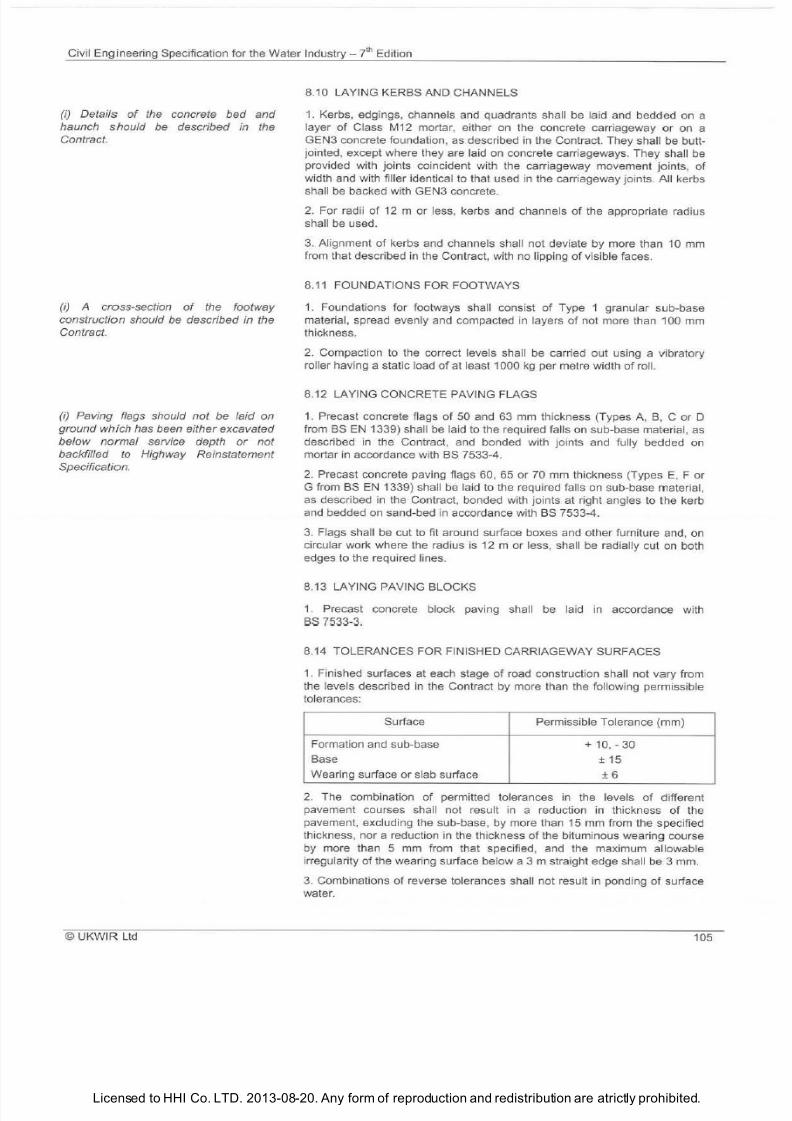
7/21/2019 The Civil Engineering Specification for the Water Industry 7th
http://slidepdf.com/reader/full/the-civil-engineering-specification-for-the-water-industry-7th 111/176Licensed to HHI Co. LTD. 2013-08-20. Any form of reproduction and redistribution are atrictly prohibited.
Civil Engineering Specification for the Wa t
er
Industry- 7
t
Edition
f) Details
o
the concrete bed and
haunch should be described in the
Contract.
f) A cross-section
o
the footway
construction should be described in the
Contract.
i)
Paving flags should not be laid on
ground which has been either excavated
below normal service depth
or
not
backfilled to Highway Reinstatement
Specification.
UKWIR Ltd
8.10
LA
YI NG KERBS AND CHANNELS
1. Kerbs, edgings, channels and quadrants shall be laid and bedded on a
layer of Class M12 mortar, either
on
the concrete carriageway or on a
GEN3 concrete foundation, as described in the Contract. They shall be butt
jointed, except where they are laid on concrete carriageways. They shal l be
provided with joints coincident with the carriageway movement joints, of
width and with filler identical to that used in the carriageway joints. All kerbs
shall
be
backed with GEN3 concrete.
2.
For radi i
of
12 m or less, kerbs and channels
of
the appropriate radius
sha ll
be
used.
3.
Alignment
of
kerbs and channels shall not deviate by more than 10 mm
from that described in the Contract, with no lipping
of
visible faces.
8.11 FOUNDATIONS FOR FOOTWAYS
1. Foundations for footways sha ll consist
of
Type 1 granular sub-base
material, spread evenly and compacted in layers
of
not more than 100 mm
thickness.
2.
Compaction to the correct levels shall be carried out using a vibratory
ro
ll
er havi
ng
a static load
of at
least 1000 kg per metre width
of
roll.
8.12 LAYING
CO
NCRETE PAVING FLAGS
1. Precast
co
ncrete flags of
50
and 63 mm th ickness (Types A, B, C or D
from BS EN 1339) sha ll
be
laid to the required falls on sub-base material, as
described in the Contract, and bonded with jo ints and fully bedded on
mortar in accordance with BS 7533-4.
2. Precast concrete paving flags 60, 65 or 70 mm thickness (Types E F or
G from
BS
EN 1339) shall
be
la id
to
the required falls on sub-base material,
as described in the Contract, bonded with joints at right angles to the kerb
and bedded on sand-bed
in
accordance with BS 7533-4.
3. Fl
ags shall
be
cut to fit arou
nd
surface boxes and other furniture and, on
circu lar work where the radius is 12 m or less, shall be radially cu t on both
edges to the required lines.
8.13 LAYING PAVING BLOCKS
1.
Precast concrete block paving shall be laid in accordance with
BS
7533-3.
8.14 TOLERANCES FOR FINISHED CARRIAGEWAY SURFACES
1.
Finished surfaces at each stage
of
road construction
sha ll
not vary from
the levels described in the Contract by more than the fo
ll
owing permissible
tolera nces:
Surface Permissible Tolerance (mm)
Formation and sub-base
10
, -30
Base
± 15
Wearing surface or slab surface
± 6
2.
The combination
of
permitted tolerances in the levels
of
different
pavement courses shall not result in a reduction ill thickness
of
the
pavement, excluding the sub-base, by more than 15 mm from the specified
th ickness, nor a reduction in the th ickness
of
the bituminous wearing course
by more than 5 mm from that specified, and the maximum allowable
irregularity
of
the wearing surface below a 3 m straight edge shall be 3 mm.
3. Combinations
of
reverse tolerances sha ll not resu lt in pending
of
surface
water.
105
7/21/2019 The Civil Engineering Specification for the Water Industry 7th
http://slidepdf.com/reader/full/the-civil-engineering-specification-for-the-water-industry-7th 112/176Licensed to HHI Co. LTD. 2013-08-20. Any form of reproduction and redistribution are atrictly prohibited.
Civil Engineering Specification for the Water Industry 7t Edition
i) Road traffic signs should be provided
in accordance with the the Traffic Signs
Regulations and General Directions,
2002, published y
The
Stationery
Office.
(ii) Deployment of traffic signs should be
as
Safety at Street Works and Road
Works, 2002, published by
The
Stationery Office.
106
8 15 FIXING OF GULLIES
1
Gullies shall
be
bedded and surrounded with GEN3 concrete to the
thickness described in the Contract.
2
Frames shall be bedded in epoxy mortar on two courses
of
Class
B
engineering brickwork or precast concrete gully cover slabs.
8.16 LINING AND SIGNAGE
1 Permanent road markings shall be applied in accordance with
BS 3262-3.
8.17 CONCRETE FOOTWAYS
1 Where in-situ concrete footways are constructed the final surface shall
have a brush finish with a minimum 60 mm smooth trowelled margin at the
edge.
©UKWIR Ltd
7/21/2019 The Civil Engineering Specification for the Water Industry 7th
http://slidepdf.com/reader/full/the-civil-engineering-specification-for-the-water-industry-7th 113/176Licensed to HHI Co. LTD. 2013-08-20. Any form of reproduction and redistribution are atrictly prohibited.
Civil Engineering Specification for the Water
Industry 7l
Edition
The Notes for Guidance are not part
of
the Specification.
i) This Section covers the fundamental
requirements of sewer renovation based
on the recommendations of the
Sewerage Rehabilitation Manual , 5th
Edition), 2001 published by
WRc
pic.
(ii) The Contract should describe
requirements for:
a)
the interface with the existing
operational system to avoid unplanned
disruption of services to customers and
pollution incidents;
b) dealing with any unusually
aggressive effluents; and
c) dealing
with
existing flows to
maintain levels of service.
(iii) Attention is directed to BS EN 13566
Plastics Piping Systems for Renovation
of Underground Non-pressure Drainage
and Sewerage Networks, Part
1:
General, Part 2: Lining with Continuous
Pipes,
Part
3: Lining with Close Fit
Pipes, Part
4:
Lining with Cured-in-place
Pipes .
iv) Reference should be made to
Report
U 1464 Typical Specifications
for Trenchless Technology Systems,
1995 published by WRc pic.
i)
Example flow schedules are given in
the Sewerage Rehabilitation Manual
(5th Edition), 2001 published by
WRc
pic.
(ii) Where the Contractor will be
permitted to operate flow control devices
and
isolate flows, this should be
described in the Contract.
i)
Details
of
the structural condition
survey should be described in the
Contract.
©
UKWIR Ltd
SECTION
SEWER RENOVATION
9 1 ISOLATION OF FLOWS
1
Flows shall be positively dealt with or isolated from the section being
renovated.
9.2 PREPARATORY SURVEY
1
T
he
sewers to be renovated sha
ll
be surve
yed
to determine the position
size and angle
of
approach
of
all laterals to an accuracy appropriate to the
method
of
reconnection.
2
A survey
of
the structural condition
of
the sewers and associated flow
control devices shall
be
carried out.
3 All flow contro l devices shall be operable prior to the commencement
of
sewer renovation works.
4 Prior to ordering any materials the sewer dimensions shall be confirmed
from the survey.
1 7
7/21/2019 The Civil Engineering Specification for the Water Industry 7th
http://slidepdf.com/reader/full/the-civil-engineering-specification-for-the-water-industry-7th 114/176Licensed to HHI Co. LTD. 2013-08-20. Any form of reproduction and redistribution are atrictly prohibited.
Civil Engineering Specification for the Water
Industry ? h
Edition
i) The Contract should describe where
flow control devices
m y
be operated.
i) The period between sewer lining nd
reconnection of laterals should be
described in the Contract.
i) Due regard must be paid to the
disposal
of
curing liquors to avoid
pollution.
ii) The Environment Agency, SEPA and
NIEA provide advice to industry nd the
public on their legal responsibilities and
good environmental practice through a
series of Pollution Prevention Guidance
108
5. Any sewer pressure main to be renovated shall be surveyed to determine
its position, size, material and structural condition , and the location and
operability
of
all fittings that may impede the insertion of the liner.
9.3 PREPARATION OF SEWERS
1. Sewers to be renovated shall be prepared so that the installation and
performance
of
the renovation system is not impaired. The installation
method and preparation shall not affect the stability
of
the existing sewer.
2. Debris shall be prevented from being carried downstream whilst
preparing
or
working in existing sewers. Such debris is to be removed from
the sewer.
3.
Intruding laterals shall be finished flush prior to the application
of
any
lining system.
4. Loose or unsound brickwork or masonry in man-entry sewers shall be
repaired using Class A engineering bricks and Class M12 mortar, with all
joints completely filled before other phases
of
rehabilitation.
5.
All substrate surfaces shall be stated in the Contract.
6
Pressure pipelines shall be thoroughly cleaned to remove all rust,
tuberculation, deposits, loose
or
deteriorated remains of
any
original
coatings and other foreign materials from the inside
of
the pipe,
to
produce
a smooth surface finish.
7.
Valves, bends and other fittings shall be removed , as appropriate,
to
enable the liner
to
be correctly insta lled.
9.4
JOINTING GENERALLY
1. Jointing surfaces and components shall be kept clean and free from
extraneous matter until the joints have been made
or
assembled.
9.5 CONNECTIONS
1. All laterals and branches shall be reconnected following sewer renovation
works. Any circumferential lining joints shall not be made at , or within
100 mm of, a connection.
2. Each finished connection shall be made flush with the lining and shall
provide a smooth transition.
3. Cured-in-place lateral connection collars ( Top Hats ) shall be Class B in
accordance with BS
EN
13566 4. The rim shall extend for more than 50%
of
the circumference of the main pipe.
9.6 CHAMBERS
1. In chambers, where applicable, the edges of the lining shall be
adequately sealed and the benching made good.
2. Brick chambers shall be repaired with Class B Engineering bri
cks
bedded
on Class M12 mortar.
3.
Exposed edges
or
ends of plastics liners shall be mechanically anchored .
9.7
RELEASE OF CURING WATER
1.
Whenever
hot
water curing of a lining system is carried out, the water
shall not be released until it cools below 4o•c.
2.
Prior approval from the Client shall be obtained before the re lease
of
curing water.
©UKWIR Ltd
7/21/2019 The Civil Engineering Specification for the Water Industry 7th
http://slidepdf.com/reader/full/the-civil-engineering-specification-for-the-water-industry-7th 115/176Licensed to HHI Co. LTD. 2013-08-20. Any form of reproduction and redistribution are atrictly prohibited.
Civil Engineering Specification for the Water Industry 7 ' Edition
Notes PPGs), see www.environment
agency.gov.uk.
i)
Any alternative restrictions on
maximum grout pressures should be
described
in
the Contract.
ii)
The
grouting materials should be
detailed
in the
Contract.
i) The
format
of
the information
required, and any need for a CCTV
survey, should be described in the
Contract.
ii)
The
number
of
samples to be
removed
nd
the length
of
the sample
should be described in the Contract.
Where appropriate, a control sample
should be provided, in advance
of
the
renovation commencing, to compare
with samples taken at completion.
iii) The sampling and acceptance of
cured-in-place lateral connection collars
should be s detailed in the Contract.
©UKWIR td
9.8 ANNULUS GROUTING GENERALLY
1. A ll air, water and contaminated grout are to be expelled from the annulus
by the grouting process.
2. The grout injection pressure shall be continuously measured by a suitable
gauge and shall not exceed 50 kN/m
2
.
3. The quantity
of
grout injected
at
each injection point and the maximum
pressure at the nozzle at that point shall be recorded.
4 Disposal
of
grout
to
live sewers is
not
permitted.
5
Annulus grouting shall closely follow the placing
of
any lining segments.
6 The applied grouting pressure sha
ll
not exceed the design external
pressure for the liner unless the li
ner
is interna
ll
y pressurised during
grouting or other internal support provided.
9.9 INSPECTION AFTER GROUTING
1. The main sewer, branches
or
laterals shall be inspected immediately
after each grouting operation and any excess grout cleaned out.
9.10 LINING THROUGH FLOW CONTROL DEVICES
1. Any flow control devices lined in-situ shall be operated throughout their
fu
ll travel, several times immediately after lining, in order
to
ensure free
operation.
9.11 INSPECTION AFTER RENOVATION
1. On completion
of
the renovation, a survey shall be undertaken and a
record
of
that survey provided to the Client. Where man-
entry
is not
possible, a CCTV survey shall be carried out, including the use of a pan and
tilt camera, where laterals are included in the length concerned.
2. Pipe samples shall be taken to check lining performance and to
determine the thickness. The lining shall be made good after the samples
have been taken. The monitoring of renovation wil l be used
to
determine the
location
of
samples. The pipe samples shall be provided to the Client.
3. The method
of
localised air testing shall be in accordance with Clause 13
of BS EN 1610:1998
9.12 LINING TEMPLATE
1.
For
man-entry sewers, a lining template shall be drawn through the sewer
prior to ordering the lining to prove the suitability
of
the profile. If
necessary, the template shall be adjusted and the proving operation
repeated until a suitable profile is established.
2.
For
non-man-entry sewers, immediately prior to installation a proving pig
with solid ends
of
sufficient rigidity and length to represent the proposed
lining system shall be passed down the sewer length to be relined.
9.13 LINING DESIGN
1. The lining design sha
ll
be
in
accordance with the 'Sewerage
Rehabi
li
tation Manual' (5th Edition), 2001 , published by WRc pic.
109
7/21/2019 The Civil Engineering Specification for the Water Industry 7th
http://slidepdf.com/reader/full/the-civil-engineering-specification-for-the-water-industry-7th 116/176Licensed to HHI Co. LTD. 2013-08-20. Any form of reproduction and redistribution are atrictly prohibited.
Civil Engineering Specification for the Water Industry th Edition
i) Any requirements for rendering and
local repairs should be described
in
the
Contract
110
9.14 TOLERANCES FOR PREFORMED LININGS
1 The position of the internal face of any unit shall not deviate by more than
±
20
mm
from the agreed profile. No section
of
lining shall have a backfall.
2
Lipping between adjacent un its shall not exceed 5 mm
9.15
CUTIING
AND PROTECTI
ON
OF LININGS
1 Linings shall be cut in accordance with the manufacturer s instructions.
2 Cut edges
of
GRP shall be sealed
in
accordance with WIS 4-34-02.
3 The ends of polyethylene and polypropylene linings shall be mechanically
anchored using suitable fixings.
4. At the upstream end
of the
lining, the original invert shall be broken out
and the lining unit laid on a Class M12 mortar bed so that the inverts of the
lining and the host pipe are correctly aligned.
9.
16
MAN-ENTRY PREFORMED GRP AND GRC UNITS
1 Each lining unit shall be laid to the mean line and level
of
the existing
sewer and
be
packed, in a minimum
of
four suitably-spaced positions, with
chemically inert spacers
of
no greater strength than the grout used to fill the
annulus.
2 The annulus shall not be less than 10 mm in width.
9.17 CURED-IN-PLACE LINI
NG
SYSTEMS
1 All cured-in-place linings shall be designed, manufactured, constructed,
tested, inspected and certified in accordance with BS EN 13566-4.
2 Cured-in-place linings for resisting infiltration shall pass the leak tightness
test set out
in
WRc pic Report CP308 Procedures for Testing the Capability
of
Cured-in-place Pipe (CIPP) Lining Systems to Resist Infiltration .
9.18 RENDERING AND LOCAL REPAIRS
1
All bricks intruding into
the
barrel shall
be
removed and replaced from
inside the sewer.
9.19 PATCH REPAIRS
1. Cured-in-place patch repairs shall
be
leaktight and shall comply wi
th
WIS 4-34-06.
2 The materials used to fabricate the patch shall conform to the
requirements
of
Clause 4.2 of WIS 4-34-06:2010.
3
The patch linings shall be fabricated
in
accordance with Clause 4.3 of
WIS 4-34-06:2010.
4. The materials used for cured-in-place patch repairs for structural
enhancement shall incorporate a means of anchorage that will continue to
function after all initial shrinkage has occurred.
5 Where a complete pipe length (from joint to joint) requires a repair, the
patch shall extend the full length
of
the pipe Ooint to joint) and beyond the
pipe joints by a minimum of 100 mm
6
Where a repair is required within a pipe length, the repair shall extend by
a minimum
of
100 mm either si
de
of the defect, except where the repair
crosses a
jo
int, then Clause 9.19.5 shall apply
7
Where it is necessary to overlap patches, the overlap shall
be
a minimum
of 150 mm.
UKWIR Ltd
7/21/2019 The Civil Engineering Specification for the Water Industry 7th
http://slidepdf.com/reader/full/the-civil-engineering-specification-for-the-water-industry-7th 117/176Licensed to HHI Co. LTD. 2013-08-20. Any form of reproduction and redistribution are atrictly prohibited.
Civil Engineering Specification for the Water
Industry
7
t
Edition
i) To prevent styrene fumes being
forced into laterals and properties, air
extraction should be used to draw the
fumes out of the sewer from the working
manhole. Extractor fans should ventilate
the lined sewer from upstream to
downstream.
i) In the absence ofa standard for spray
polymeric linings for wastewater
applications, the guidance given in as
N
13566 should be followed.
ii)
The
method
of
testing polymeric
spray linings should be as stated in the
Contract.
© UKWIR Ltd
8 The Contractor shall specify the method of installation in accordance with
Clause 4.3 of WIS 4-34-06:2010.
9.20 STYRENE FUMES
1
The Contractor shall take all precautions to prevent styrene fumes from
cured-in-place linings or patch repairs entering the properties v ia their
laterals. A suitable monitor to measure the styrene fumes level shall also be
available on Site.
9 21 SPRAY LINING
1 Dimensional requirements material tests and measurements are to
be
in
accordance with
BS EN
13566-4.
111
7/21/2019 The Civil Engineering Specification for the Water Industry 7th
http://slidepdf.com/reader/full/the-civil-engineering-specification-for-the-water-industry-7th 118/176Licensed to HHI Co. LTD. 2013-08-20. Any form of reproduction and redistribution are atrictly prohibited.
Civil Engineering Specification for the Water
Industry t
Edition
2
©UKWIR
Ltd
7/21/2019 The Civil Engineering Specification for the Water Industry 7th
http://slidepdf.com/reader/full/the-civil-engineering-specification-for-the-water-industry-7th 119/176Licensed to HHI Co. LTD. 2013-08-20. Any form of reproduction and redistribution are atrictly prohibited.
Civil Engineering Specification for the Water Industry 7lh Edition
The Notes for Guidance are not part
of
the Specification.
(i) This Section covers the fundamental
requirements of water mains
rehabilitation based on the
recommendations
of
the Water Mains
Rehabilitation Manual , 1999, published
by W cplc
.
(ii)
The
Contract should describe
requirements for:
(a) the interface with the existing
operational system to avoid unplanned
disruption
of
services to customers and
pollution incidents;
{b) dealing with existing flows to
maintain levels of service; and
(c) where valves and hydrants may be
operated.
i) Due regard should be paid to the
release
of
toxic
gases and odours from
the installation of epoxy lining systems.
i) The period between pipe lining and
reconnection of services should be
described
in
the Contract.
© UKWIR Ltd
SECTION 1
WATER MAINS RENOVATION
1
0.
1 PREPARATORY SURVEY
1. The water mains to be rehabilitated shall be surveyed to determine their
position, size, material and structural condition, and the location
and
operability of all fittings.
10.2 PREPARATION OF WATER MAINS
1.
Water mains
to be
re-lined shall
be
prepared internally such that the
performance of the lining system is not impaired.
10.3 IN-SITU LININGS
1 The measures to be taken to control the release of odours and gases
arising from the Works
shall be
stated in the Contract.
2. The
in
-situ lining of water mains with epoxy resin shall be
in
accordance
with the, Code of Practice: In-situ Resin Linings of Water Mains {IGN 4-02-
02) and Operational Requirements: In-situ Resin Lining of Water Mains
(WIS 4-02-01) published by Water UK.
3.
The in-situ lining of water mains with cement mortar shall be in
accordance with the In-situ Cement Mortar Lining - Operational Guidelines
and Code of Practice . published by WRc pic.
4. The in-situ lining of water mains with polymeric linings shall be
in
accordance with the Code of Practice: In-situ Resin Linings of Water Mains
IGN 4-02-02) and the Operational Requirements: In-situ Resin Lining of
Water Mains (WIS 4-02-01 ). published by Water UK.
10.4 SLIPLINING AND REPLACEMENT MOLING
1. The use of sliplining and moling techniques shall be
in
accordance with
Siiplining and Replacement Mol ing of Water Mai
ns
- Operational
Guidelines pub
li
shed by WRc pic.
2. The annular void shall be grouted unless otherwise stated in the
Contract.
113
7/21/2019 The Civil Engineering Specification for the Water Industry 7th
http://slidepdf.com/reader/full/the-civil-engineering-specification-for-the-water-industry-7th 120/176Licensed to HHI Co. LTD. 2013-08-20. Any form of reproduction and redistribution are atrictly prohibited.
Civil Engineering Specification for the Water Industry
t
Edition
i) Th
e format
o
the information required
and CCTV survey should be described
in the Contract.
ii) The number o samples to be
removed and the length o the sample
should be described in the Contract.
Where appropriate, a control sample
should be provided, in advance
o
the
renovation commencing, to compare
with samples taken at completion.
114
10.5 CONNECTIONS
1 Service connections shall be disconnected and reconnected as required
for the work.
10.6 LINING THROUGH VALVES
1
Any valves lined in-situ shall be operated throughout their full travel
several times immediately after lining in order to ensure free operation.
There shall be no in-situ lining through valves of pipelines of non-man-entry
sizes.
10.7 INSPECTION AFTER IN-SITU RE-LINING
1 On completion of the rehabilitation a survey shall be undertaken and a
record
of
that survey shall be supplied to the Client.
2 Pipe samples sha ll be taken and provided to the Client in order to check
lining performance and to determine thickness. The lining shall
be
made
good after the samples have been taken. The monitoring
of
rehabilitation
will be used to determine the location of samples.
10.8 BRINGING REHABILITATED WATER MAINS INTO SERVICE
1 Before returning any rehabilitated water ma in into service the ma in shall
be
cleaned and disinfected.
©UKWIR
Ltd
7/21/2019 The Civil Engineering Specification for the Water Industry 7th
http://slidepdf.com/reader/full/the-civil-engineering-specification-for-the-water-industry-7th 121/176Licensed to HHI Co. LTD. 2013-08-20. Any form of reproduction and redistribution are atrictly prohibited.
Civil Engineering Specification for the Water Industry J h Edition
The Notes for Guidance are not part
of
the Specification.
(i)
or
further guidance,
see
British
Tunnelling Society and Institution of Civil
Engineers Specification for Tunnelling .
(il) Where appropriate, particularly in
areas of previous mining activity,
probing
ahead
requirements should be
described in the Contract.
(iii) This Section, as well as dealing with
tunnelling
and
shaft sinking, provides for
thrust
boring
.
(iv)
The
need for any ground
investigation ahead of the face of any
tunnel, heading or shaft should be
described
in
the Contract.
i)
Any special requirements relating to
protection should be described in the
Contract.
(ii) Special Clauses will be required
for
other types of shaft sinking.
i)
The Contract should describe any
limitations which the design of he tunnel
or
shaft will impose on temporary
openings.
© UKWIR l td
SECTION
TUNNELLING ND SH FT SINKING WORKS
11 1 HEADINGS, TUNNELS AND SHAFTS
1 Any restrictions on vehicle movements and working hours shall be as
stated in the Contract.
2 On Site storage capacity required for excavated materials shall be stated
in the Contract.
3 Excavations for headings and tunnels shall
be
adequately supported at
all times. The faces
of
all headings and tunnels, other than those in solid
rock, shall be fully supported whenever excavation has been stopped for a
period exceeding
12
hours.
4 All working shafts shall be supplied with effective means of
communication with the Works below ground. A
fa
il-safe back-up means
of
communication shall also
be
provided.
11 2 SHAFTS
1 A safe means
of
access and egress shall
be
provided in compliance with
BS
6164
A
ll
shafts shall
be
provided with a primary and secondary means
of access and egress. A ladder access shall be provided in addition to any
mechanical means.
2 Segments used in shafts shall be so erected as to break vertical joints,
except in any rings required to be broken out.
3 Where shafts are constructed by underpinning and lined with segments,
they sha ll be grouted up
at
least once per shift.
4 Where segmental shafts are sunk by caisson methods, an annulus sha ll
be maintained by a lubricant which shall be replaced with a grout on
completion.
5 After any primary lining is complete and before any openings are made at
or
near the foot, the excavation for the base
of
the shaft shall be taken out
and the base concreted.
11.3 OPENINGS
IN
SHAFTS AND TUNNELS
1 Drawings shall be provided showing proposals for forming openings in
shafts and tunnels. These Drawings shall include details of temporary
supports to the lining and to the ground.
2 Openings in shafts and tunnels shall only
be
made after the segments
have been grouted.
11.4 SEGMENTAL SHAFT AND TUNNEL LININGS
1
Segments shall be erected and assembled in accordance with the
manufacturer s instructions and the Contractor s method statement. The
lining shall
be
built as soon as possib le after the ground has been cut.
115
7/21/2019 The Civil Engineering Specification for the Water Industry 7th
http://slidepdf.com/reader/full/the-civil-engineering-specification-for-the-water-industry-7th 122/176Licensed to HHI Co. LTD. 2013-08-20. Any form of reproduction and redistribution are atrictly prohibited.
Civil Engineering Specification for the Water Industry - 7
t
Edition
{i)
Requirements for any circumferential
pre-stress should be described in the
Contract.
i)
ny requirement relating to rolling
of
segments should be described in the
Contract.
i)
ny
requirements for high pressure
grouting should be described in the
Contract.
ii) ny locations where it is required to
grout more frequently than once
per
shift
should be described in the Contract.
iii) When selecting grout, due regard
should be given to its specification to
ensure that local aquifers are not
polluted.
iv) A pressure gauge should be fitted
onto the grouting nozzle to avoid ground
heave, overstress
or
distorlion.
i) Material to be used for caulking
should be described in the Contract.
ii) The time when caulking is carried out
may depend, for example, upon ground
conditions and availability of the working
area.
116
11.5 UNBOLTED CONCRETE TUNNEL SEGMENTS
1. The shape of unbolted concrete segmental tunnels shall
be
maintained
within tolerance after erection, until the segments have been stabilised by
grout or other means.
2
Where a circumferential pre-stress is applied, the force shall
be
such that
the whole
of
the concrete lining is expanded tight against the surrounding
ground. A joint lubricating compound shall be applied to all wedge faces of
each segment to be expanded.
3 Where wedge block segments are specified, the excavated profile shall
be
lubricated to reduce skin friction .
4. Where key segments are shorter than other segments comprising the
ring, the pockets formed shall be filled with concrete to the grade specified
in the Contract.
11.6 BOLTED CONCRETE SEGMENTAL LIN
INGS
1 Segmental joints to bolted concrete tunnel and shaft linings shall be trued
and longitudinal joint bolts tightened before the final tightening of
the
circumferential joint bolts connecting the ring to the adjacent ring.
2 Packings shall
be
inserted
in
the joints
of
the lining at the time
of
erection,
as required, to ma in tain correct shape, line and level, and shall not exceed
6 mm or half of the sealing capacity of the gasket.
3 Segments shall
be
fixed in accordance with manufacturer s
recommendations. Where grummets are to be used, two grummets shall be
threaded on each bolt to be grummetted at the time any bolted segment is
erected. One grummet shall be placed under
the
washer t the head of
the
bolt and the other under the washer at the nut.
11
.7 GROUTING OF SEGMENTS
1
Segmental shaft and tunnel linings shall be grouted by forcing the
required grout through the grouti
ng
holes in the segments, so that all
interstices around the outside
of
the segments are filled . Adequate venting
shall be provided to ensure that air is not trapped.
2
Temporary hardwood plugs shall be inserted into grout holes after
grouting; these shall be replaced by permanent plugs
of
material similar to
that
of
the segments being grouted when it is evident to the Client that
grouting has been effective.
3 Grout pipes shall be provided in head walls or ring walls , and any void
remaining after concreting shall
be filled with the required grout.
4 Where primary grouting does not completely fill al l cavities, secondary
grouting shall be carried out.
5 Grouting shall closely follow the erection of rings, be undertaken every
four rings, and t least twice per shift.
11 .8 CAULKING
1 Caulking of segment joints in tunnels and shafts shall
be
carri ed out as
late as practicable within the construction programme; the grooves shall be
raked out and cleaned immediately before caulking.
2
Caulking
of
circumferenti
al
and longitudinal joints shall be bonded to form
a homogeneous and continuous mass, consolidated to fill the recess up to
the inner surface of the segment or to the depths described
in
the Contract.
11.9 POINTING OF JOINTS
1 Where joints between segments are required to be pointed, they shall be
raked out, cleaned, filled with a proprietary non-shrink cement mortar and
pointed flush.
UKWIR Ltd
7/21/2019 The Civil Engineering Specification for the Water Industry 7th
http://slidepdf.com/reader/full/the-civil-engineering-specification-for-the-water-industry-7th 123/176Licensed to HHI Co. LTD. 2013-08-20. Any form of reproduction and redistribution are atrictly prohibited.
Civil Engineering Specification for the Water Industry ? h Edition
i) The specification
of
the lining and the
surface finish should be stated in the
Contract.
i)
See a/so Clause
7.8.
i)
Advice on the design and
construction of pipejacks
s
given in 'A
Guide to Best Practice for the
Installation of Pipejacks and
Microtunnels: published by the Pipe
Jacking Association.
ii) Collars fabricated from weldable
structural steel may be susceptible to
corrosion from the ground, groundwater
or the effluent carried.
f
corrosion can
be expected, the design
of
the joint
should provide for a secondary sealing
gasket to be applied on Site.
iii) The
material required to seal the
ioints should be described in the
Contract.
©U
KWIR
l td
11.10 SECONDARY LININGS TO SEGMENTS
1
Before construction
of
a secondary internal lining to a segmental tunnel is
commenced, it shall
be
cleaned out, caulked and proven to
be
watertight.
2 The minimum thickness
of
lining over the ribs
of
the segments shall be
agreed in advance with the Client, unless otherwise stated in the Contract.
11.11 WATERTIGHTNESS OF SHAFTS AND TUNNELS
1 Shafts and tunnels shall be substantially watertight, with no identifiable
flow
of
water penetrating either the primary or secondary lining.
11.12 CONTROL OF GROUNDWATER
1
Working methods and systems shall be designed to control groundwater
and, where necessary, to remove water from the tunnel. Removal of
groundwater shall not cause damage to the Works nor to the property of
third parties.
11.13 PIPE JACKING
1 Excavation for pipe jacking shall be undertaken from within a shield
equipped with steering jacks for adjusting the alignment. Face boards shall
be available for boarding up the exposed excavation.
2
The jacking load applied to the pipeline shall be limited
so
that damage to
the pipes is avoided and
an
intermediate jacking station shall be provided,
where necessary,
to
achieve
th
is
3 The jacking load shall be transferred to
the
pipes through a thrust ring,
which shall be sufficiently rigid to ensure even distribution
of
the load.
4 The pipe manufacturer's permitted draw or angular deflection shall not be
exceeded at any individual joint.
5
Up-to-date records shall be maintained
of
jacking loads and line and level
measurements. A graphical relationship between the jacking force and the
distance moved shall
be
produced to ensure that the necessary measures
are taken to avoid exceeding the maximum permitted jacking forces.
6 All lifting holes
and
grouting holes shall
be
sealed.
7 Joint packing material designed to distribute the jacking load evenly shall
be
inserted at,
and
between, the pipe ends, and at any intermediate jacking
stations.
8. Before work may start on any thrust pit, it shall be demonstrated that the
design will withstand the maximum jacking force
of
which the jacks are
capable.
9
Before a particular pipe jack may commence, evidence shall be provided
that the pipes necessary for completing the jack are on Site or in storage
elsewher
e
The envisaged number of intermediate jacking stations shall be
agreed in advance
of
commencement. At least one intermediate jacking
station assembly shall be available at the start of the pipe jack, unless
otherwise agreed.
10. Pipes, including lead pipes, which have been jacked through a pipe jack
shall not be used elsewhere on the Works. Cut pipes shall not be jacked.
11. Pipe jacking shall
be
undertaken in a continuous operation and the
jacking load shall be limited so that installed joints are prevented from
opening when the jacking loads are removed.
12 . On completion of the drive, intermediate jacking stations shall be left
fully closed. All jacks, props, thrust rings and packing sha
ll
be removed, the
ends of the pipes cleaned, a new packing ring glued to the receiving face
and the joint jacked partly closed. An
0 ring seal shall then be inserted
into the sliding joint and the joint jacked fully closed. The order of closing the
stations shall be from the tunnelling shield working back.
117
7/21/2019 The Civil Engineering Specification for the Water Industry 7th
http://slidepdf.com/reader/full/the-civil-engineering-specification-for-the-water-industry-7th 124/176Licensed to HHI Co. LTD. 2013-08-20. Any form of reproduction and redistribution are atrictly prohibited.
Civil Engineering Specification for the Water Industry 7t Edition
i) See also the Construction (Health,
Safety and Welfare) Regulations , 1996,
the Construction (Health, Safety and
Welfare) Regulations (Northern Ireland)
1996,
as
6164 and HSE Guidance Note
EH40.
i) The
Work in Compressed
ir
Regulations ,
1996,
(and the Work in
Compressed ir Regulations (Northern
Ireland), 2004) and the accompanying
Guidance Notes should be referred
to
when carrying out work in compressed
air.
(ii)
The
CIRIA Report R44 gives
recommendations as to standards of
good practice for work in compressed
air.
(iii)
The
appropriate provision
of
as
6164 also applies.
i)
Where a tunnel is to have
secondary lining, it may be necessary to
specify permissible deviations for the
primary lining, having regard to the
nature
of
he work.
118
13. The annular space between the sides of the excavated tunnel and the
jacking pipes shall be constantly filled with an approved lubricant at a
pressure that will support the adjacent excavation. Daily records
of
the
quantity of lubricant used for each length of pipe thrust and the point at
which the lubricant was injected shall be submitted to the Client. The
lubricant shall be thoroughly mixed prior to pumping or placing. On
completion of the pipe jack the annulus shall be filled by disp lac ing the
lubricant with grout.
11 .14 MICROTUNNELLING
1
The microtunnelling machine shall be selected with regard to the ground
conditions length
of
drive and other relevant factors.
2
Microtunnelling shall comply generally with the provisions of Clause
11.13.
11.15 VEN
TILATION OF TUNNELS AND SHAFTS
1
Sufficient ventilation throughout the tunnels and shafts shall be provided
to ensure that a safe working environment is maintained at all times.
11.16 WORK IN COMPRESSED AIR
1
Fu
ll
details sha
ll
be submitted to the C
li
ent
of the
type capacity and
arrangement of the compressed air plant ancillary equipment and medical
facilities it is proposed to install.
2. All standby plant shall be tested weekly by using it to supply air to the
Works under normal working conditions.
3
After installation but before work in compressed air is commenced all
compressed air plant shall
be
given a 24-hour continuous running test
at
the
normal operating pressure.
11.17 RECORDING OF INFORMATION
1
Records shall be kept of the line level and the diameter measured
horizontally and vertically of any tunnel lining. Similar records shall be kept
for shafts and for pipe jacking.
11.18 TOLERANCES FOR SHAFTS TUNNELS AND PIPE JACKS
1 The position of the Internal face of any shaft or tunnel shall not deviate
from that described in the Contract by more than the fol lowing permissible
tolerances:
© UKWIR Ltd
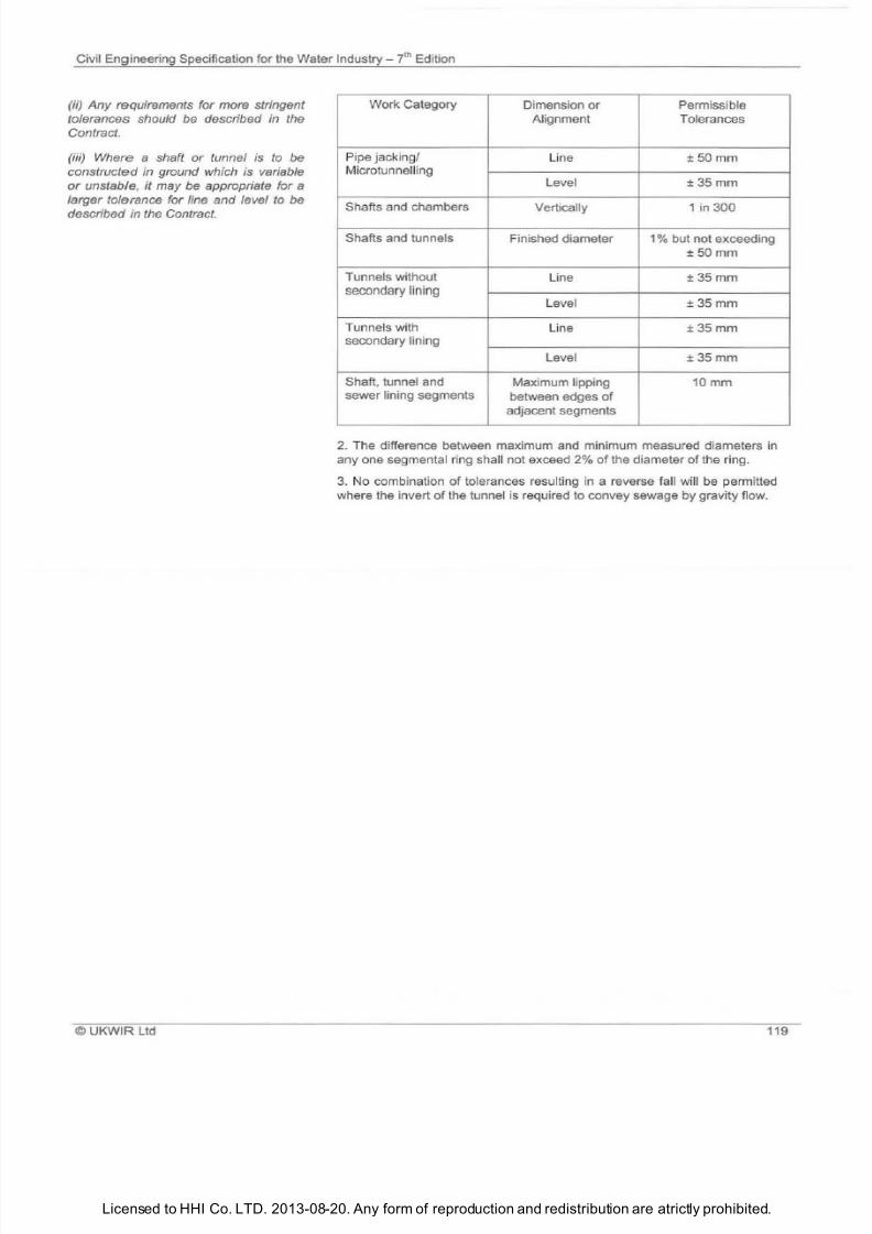
7/21/2019 The Civil Engineering Specification for the Water Industry 7th
http://slidepdf.com/reader/full/the-civil-engineering-specification-for-the-water-industry-7th 125/176Licensed to HHI Co. LTD. 2013-08-20. Any form of reproduction and redistribution are atrictly prohibited.
Civil Engineering Specification for the Water Industry 7
t
Edition
ii) Any requirements for more stringent
tolerances should
e
described in the
Contract.
iii) Where a shaft or tunnel
s to
be
constructed
in
ground which
s
variable
r
unstable, it may
e
appropriate for a
larger tolerance for line and level
to e
described in the Contract.
© UKWIR Ltd
Work Category
Dimension or Permissible
Alignment Tolerances
Pipe jacking/
Line
±50mm
Microtunnell ing
Le
vel
±35mm
Shafts and chambers
Vertically 1 in 300
Shafts and tunnels
Finished diameter 1 but not exceeding
±50mm
Tunnels without
Line
±35mm
secondary lining
Level
±35mm
Tunnels with
Line
±35mm
secondary lining
Level
±35mm
Shaft, tunnel and Maximum lippi
ng
10mm
sewer lining segments
between edges
of
adjacent segments
2 The difference between maximum and minimum measured diameters in
any one segmental ring sha
ll
not exceed
2 of
the diameter
of
the ring.
3
No combination
of
tolerances resulting In a reverse fall will
be pe
rmitted
where the invert
of
the tunnel is required to convey sewage by gravi ty flow.
119

7/21/2019 The Civil Engineering Specification for the Water Industry 7th
http://slidepdf.com/reader/full/the-civil-engineering-specification-for-the-water-industry-7th 126/176Licensed to HHI Co. LTD. 2013-08-20. Any form of reproduction and redistribution are atrictly prohibited.
ivilEngineering Specification for
the
Water ndustry
i h
Edition
12 ©
UKWIR td
7/21/2019 The Civil Engineering Specification for the Water Industry 7th
http://slidepdf.com/reader/full/the-civil-engineering-specification-for-the-water-industry-7th 127/176

7/21/2019 The Civil Engineering Specification for the Water Industry 7th
http://slidepdf.com/reader/full/the-civil-engineering-specification-for-the-water-industry-7th 128/176Licensed to HHI Co. LTD. 2013-08-20. Any form of reproduction and redistribution are atrictly prohibited.
ivil EngineeringSpecification for the Water
Industry i
Edition
22
©UKWIR Ltd
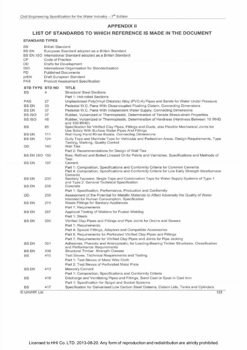
7/21/2019 The Civil Engineering Specification for the Water Industry 7th
http://slidepdf.com/reader/full/the-civil-engineering-specification-for-the-water-industry-7th 129/176Licensed to HHI Co. LTD. 2013-08-20. Any form of reproduction and redistribution are atrictly prohibited.
Civil Engineering Specification for the Water Industry 7til Edition
PPENDIX II
L ST OF ST ND RDS TO WHICH REFERENCE IS M DE N THE DOCUMENT
STANDA RD TYPES
BS British Standard
BS EN European Standard adopted as a British Standard
BS
EN I SO International Standard adopted as a British Standard
CP Code
of
Practice
DD Drafts for Development
ISO International Organisation for Standardisation
PD Published Documents
prEN Draft European Standard
PAS Product Assessment Specification
STD
TYPE
STD
NO
T
IT
LE
BS
4
Structural Steel Sections
PAS 27
BS
EN 33
BS EN 37
BSISO
37
BSISO 48
BS 65
BS EN
111
BS EN 124
DD 140
BS EN ISO 150
BS EN 197
BS EN
200
BS EN 206
256
BS EN 274
BS EN 287
BS E N 295
BSEN
3 1
BS
EN 338
BS
410
BS
EN
413
BS
416
BS
417
©
UKWIR Ltd
Part 1: Hot-rolled
Sec
tions
Unplasticised Poly Vinyl Chloride) Alloy PVC-A) Pipes
and
Bends for Water Under Pressure
Pedestal W.C. Pans With Close-coupled Flushing Cistern. Connecting Dimensions
Pedestal W.C.
Pans
With Independent Water Supply. Connecting Dimensions
Rubber, Vulcanized or Thermoplastic. Determination of Tensile Stress-strain Properties
Rubber, Vulcanized or Thermoplastic. Determination
of
Hardness Hardness Between 10 IRHD
and 100 IRHD)
Specification for Vitrified Clay Pipes, Fittings and Ducts, also Flexible Mechanical Joints for
Use
So
lely With Surface Water Pipes And Fittings
Wall-hung Hand R in
se
Basins. Connecting Dimensi
on
s
Gully Tops and Manhole Tops for Vehicular and Pedestrian Areas. Design Requirements, Type
Testing, Marking, Quality Control
Wall Ties
Part 2: Recommendations for Design of Wall Ties
Raw, Refined and Boiled Linseed Oil for Paints and Varnishes. Specifications and Methods of
Test
Cement
Part 1: Composition, Specifications and Conformity Criteria for Common Cements
Part 4: Composition, Specifications and Conformity Criteria for
Low
Early Strength Blastfurnace
Cements
Sanitary Tapware. Single Taps and Combination Taps for Water Supply Systems of Type 1
and Type
2
General Technical Specification
Concrete
Part 1: Specification, Performance, Production and Conformity
Assessment of the Potential for Metallic Materials to Affect Adversely the Quality
of Water
Intended for Human Consumption. Specification
Waste Fittings
for
Sanitary Appliances
Part 1: Requirements
Approval Testing of Welders for Fusion Welding
Part
1 :
Steels
Vitrified Clay Pipes and Fittings and Pipe Joints
fo r Drains and Sewers
Part 1 Requirements
Part 4: Special Fi ttings, Adapt
ors
and Compatible Accessories
Part 5: Requirements for Perforated Vitrified Clay Pipes and Fittings
Part 7: Requirements for Vitrified Clay Pipes and Joints for Pipe Jacking
Adhesives, Phenolic and Aminoplastic, for Loading-Bearing Timber Structures, Classification
and Performance Requirements
Structural T imber. Strength Classes
Test
Sieves. Techn ical Requirements and Testing
Part 1: Test Sieves of Metal Wire Cloth
Part 2:
Tes
t Sie
ve
s
of
Perforated Metal Plate
Masonry Cement
Part 1: Composition,
Spe
cifications and Conformity Criteria
Discharge and
Ventilating Pipes and Fittings, Sand-Cast or Spun in Cast Iron
Part 1: Specification for Spigot and Socket Systems
Specification for Galvanised
Low
Carbon Steel Cisterns, Cistern Lids, Tanks and Cylinders
123
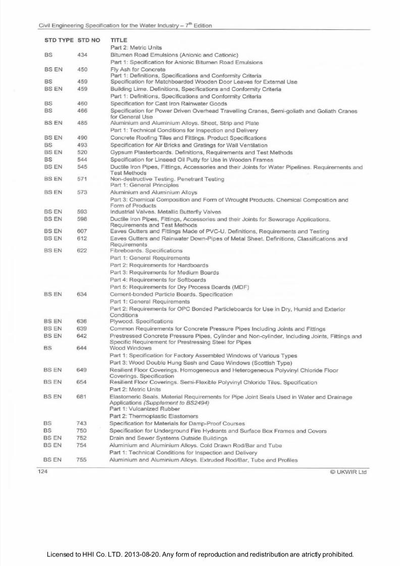
7/21/2019 The Civil Engineering Specification for the Water Industry 7th
http://slidepdf.com/reader/full/the-civil-engineering-specification-for-the-water-industry-7th 130/176Licensed to HHI Co. LTD. 2013-08-20. Any form of reproduction and redistribution are atrictly prohibited.
Civil Engineering Specification for the Water Industry - 7th Edition
ST TYPE ST O TITLE
BS
SEN
BS
BS EN
BS
BS
BS EN
BS EN
BS
BS EN
BS
BS EN
SEN
BS EN
SEN
SEN
BS EN
BS EN
BS EN
BS EN
SEN
BS EN
BS EN
BS
BS EN
BS EN
BS EN
BS
BS
SEN
SEN
SEN
124
434
45
459
459
46
466
485
49
493
52
544
545
571
573
593
598
6 7
612
622
634
636
639
642
644
649
654
681
743
75
752
754
755
Part
2:
Metric Units
Bitumen Road Emulsions Anionic and Cationic)
Part
1:
Specification for Anionic Bitumen Road Emulsions
Fly Ash for Concrete
Part
1:
Definitions, Specifications and Conformity Criteria
Specification for Matchboarded Wooden Door Leaves for External Use
Building Lime. Definitions, Specifications and Conformity Criteria
Part 1: Definition
s
Specifications and Conformity Criteria
Specification for Cast Iron Rainwater Goods
Specification for Power Driven Overhead Travelling Cranes, Semi-goliath and Goliath Cranes
for General Use
Aluminium and Aluminium Alloys. Sheet, Strip and Plate
Part 1: Technical Conditions for Inspection and Delivery
Concrete Roofing Tiles and Fittings. Product Specifications
Specification for Air Bricks and Gratings for Wall Ventilation
Gypsum Plasterboards. Definitions, Requirements and Test Methods
Specification for Linseed Oil Putty for Use in Wooden Frames
Ductile Iron Pipes, Fittings, Accessories and their Joints for Water Pipelines. Requirements and
Test Methods
Non-destructive Testing. Penetrant Testing
Part
1:
General Principles
Aluminium and Aluminium Alloys
Part
3:
Chemical Composition and Form
of
Wrought Products. Chemical Composition and
Form of Products
Industrial Valves. Metallic Butterfly Valves
Ductile Iron Pipes, Fittings, Accessories and their Joints for Sewerage Applications.
Requirements and Test Methods
Eaves Gutters and Fittings Made
of
PVC-U. Definitions, Requirements and Testing
Eaves Gutters and Rainwater Down-Pipes
of
Metal Sheet. Definitions, Classifications and
Requirements
Fibreboards. Specifications
Part 1: General Requirements
Part
2:
Requirements for Hardboards
Part 3: Requirements for Medium Boards
Part 4: Requirements for Softboards
Part 5: Requirements for Dry Process Boards MDF)
Cement-bonded Particle Boards. Specification
Part
1:
General Requirements
Part 2: Requirements for OPC Bonded Particleboards for Use in Dry, Humid and Exterior
Conditions
Plywood. Specifications
Common Requi rements for Concrete Pressure Pipes Including Joints and Fittings
Prestressed Concrete Pressure Pipes, Cylinder and Non-cylinder, Including Joints, Fittings and
Specific Requirement for Prestressing Steel for Pipes
Wood Windows
Part 1: Specification for Factory Assembled Windows
of
Various Types
Part 3: Wood Double Hung Sash and Case Windows Scottish Type)
Resilient Floor Coverings. Homogeneous and Heterogeneous Polyvinyl Chloride Floor
Coverings. Specification
Resilient Floor Coverings. Semi-Flexible Polyvinyl Ch
loride Tiles. Specificati
on
Part
2:
Metric Units
Elastomeric Seals. Material Requirements for Pipe Joint Seals Used in Water and Drainage
Applications
Supplement to BS2494)
Part
1:
Vulcanized Rubber
Part 2: Thermoplastic Elastomers
Specification for Materials for Damp-Proof Courses
Specification for Underground Fire Hydrants and Surface Box Frames and Covers
Drain and Sewer Systems Outside Buildings
Aluminium and Aluminium Alloys. Cold Drawn Rod/Bar and Tube
Part 1: Technical Conditions for Inspection and Delivery
Aluminium and Aluminium Alloys. Extruded Rod/Bar, Tube and Profiles
©
UKWIR Ltd
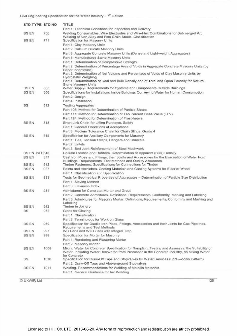
7/21/2019 The Civil Engineering Specification for the Water Industry 7th
http://slidepdf.com/reader/full/the-civil-engineering-specification-for-the-water-industry-7th 131/176Licensed to HHI Co. LTD. 2013-08-20. Any form of reproduction and redistribution are atrictly prohibited.
Civil Engineering Specification for the Water
Industry lh
Edition
STD
TYPE
STD NO TITLE
BS EN
BS EN
BS EN
BS
EN
BS
BS
EN
BS
EN
756
77
805
806
812
818
845
BS EN ISO 845
BS
EN
BS EN
BS EN
BS EN
BSEN
BS
EN
BS
BS
EN
BSEN
BSEN
BS EN
BS
BS EN
©U
KWIR Ltd
877
912
927
933
934
942
952
969
997
998
1008
1010
1011
Part
: Technical Conditions for Inspection and Delivery
Welding Consumables. Wire Electrodes and Wire-Flux Combinations for Submerged Arc
Welding of Non Alloy and Fine Grain Steels. Classification
Specification for Masonry Units
Part
:
Clay Masonry Units
Part 2: Calcium Silicate Masonry Units
Part
3:
Aggregate Concrete Masonry Units Dense and Light-weight Aggregates)
Part 5: Manufactured Stone Masonry Units
Part 1: Determination
of
Compressive Strength
Part 2: Determination of Percentage Area of Voids in Aggregate Concrete Masonry Units by
Paper Indentation)
Part 3: Determination
of
Net Volume and Percentage
of
Voids
of
Clay Masonry Units
by
Hydrostatic Weighing
Part
4:
Determination
of
Real and Bulk Density and
of
Total and Open Porosity for Natural
Stone Masonry Units
Water Supply Requirements for Systems and Components Outside Buildings
Specifications for Installations Inside Buildings Conveying Water for Human Consumption
Part 2: Design
Part
4:
Installation
Testing Aggregates
Part 105: Method for Determination of Particle Shape
Part 111 : Method for Determination
of
Ten Percent Fines Value TFV)
Part 124: Method for Determination of Frost-heave
Short Link Chain for Lifting Purposes. Safety
Part
:
General Conditions of Acceptance
Part 3: Medium Tolerance Chain for Chain Slings. Grade 4
Specification for Ancillary Components for Masonry
Part 1: Ties, Tension Straps, Hangers and Brackets
Part
2:
Lintels
Part
3:
Bed Joint Reinforcement of Steel Meshwork
Cellular Plastics and Rubbers. Determination of Apparent Bulk) Density
Cast Iron Pipes and Fittings, their Joints and Accessories for the Evacuation
of Water from
Buildings. Requirements, Test Methods and Quality Assurance
Timber Fasteners. Specifications for Connections for Timber
Paints and Varnishes. Coating Materials and Coating Systems for Exterior Wood
Part 1: Classification and Specification
Tests for Geometrical Properties of Aggregates Determination of Particle Size Distribution
Part 1: Sieving Method
Part 3: Flakiness Index
Admixtures for Concrete, Mortar and Grout
Part 2: Concrete Admixtures. Definitions, Requirements, Conformity, Marking and Labelling
Part
3:
Admixtures for Masonry Mortar. Definitions, Requirements, Conformity and Marking and
Labelling
Timber in Joinery
Glass for Glazing
Part
1:
Classification
Part 2: Terminology for Work
on
Glass
Specification for Ductile Iron Pipes, Fittings, Accessories and their Joints for Gas Pipelines.
Requirements and Test Methods
WC
Pans and
WC
Suites with Integral Trap
Specification for Mortar for Masonry
Part 1: Rendering and Plastering Mortar
Part 2: Masonry Mortar
Mixing Water for Concrete. Specification for Sampling, Testing and Assessing the Suitability
of
Water, Including Water Recovered from Processes in the Concrete Industry, as Mixing Water
for Concrete
Specification for Draw-Off Taps and Stopvalves for Water Services Screw-down Pattern)
Part
2:
Draw-Off Taps and Above-ground Stopvalves
Welding. Recommendations for Welding of Metallic Materials
Part 1: General Guidance for Arc Welding
125
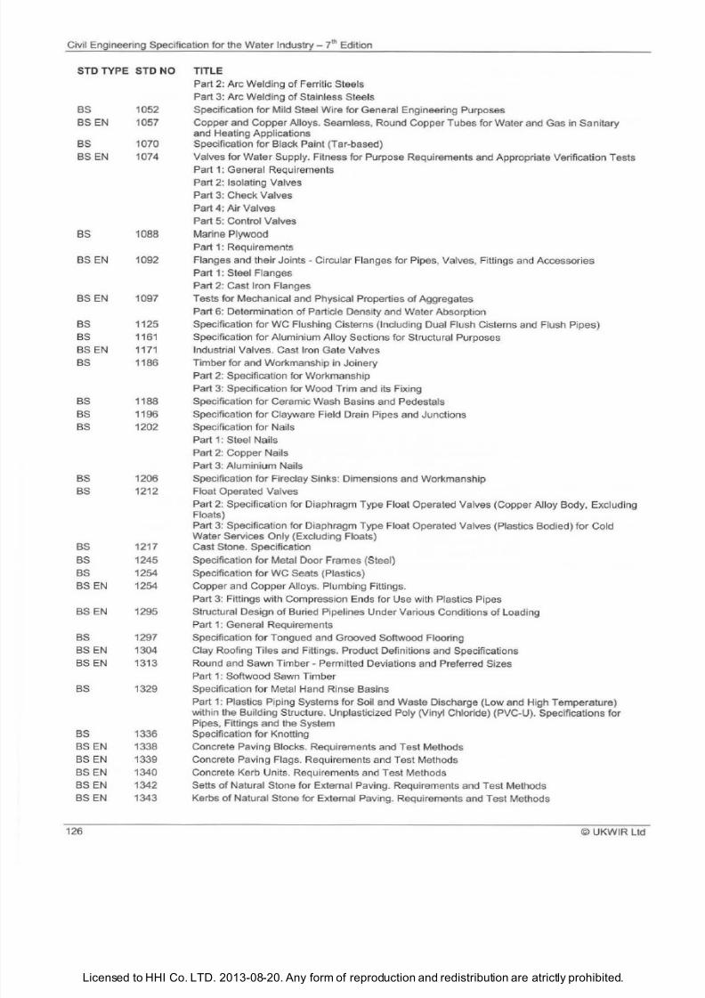
7/21/2019 The Civil Engineering Specification for the Water Industry 7th
http://slidepdf.com/reader/full/the-civil-engineering-specification-for-the-water-industry-7th 132/176Licensed to HHI Co. LTD. 2013-08-20. Any form of reproduction and redistribution are atrictly prohibited.
Civil Engineering Specification for the Water Industry - JhEdition
ST TYPE ST NO TITLE
BS
BS EN
BS
BS EN
BS
BSEN
BSEN
BS
BS
BS EN
BS
BS
BS
BS
BS
BS
BS
BS
BS
BS EN
BS EN
BS
BSEN
BSEN
BS
BS
BSEN
BS EN
BSEN
BSEN
BSEN
126
1 52
1 57
1 7
1 74
1 88
1 92
1 97
1125
1161
1171
1186
1188
1196
12 2
12 6
1212
1217
1245
1254
1254
1295
1297
13 4
1313
1329
1336
1338
1339
134
1342
1343
Part 2: Arc Welding of Ferritic Steels
Part 3: Arc Welding of Stainless Steels
Specification for Mild Steel Wire for General Engineering Purposes
Copper and Copper Alloys. Seamless, Round Copper Tubes
for
Water and Gas in Sanitary
and Heating Applications
Specification for Black Paint Tar-based)
Valves for
Water
Supply. Fitness for Purpose Requirements and Appropriate Verification Tests
Part
1:
General Requirements
Part 2: Isolating Valves
Part 3: Check Valves
Part
4:
Air Valves
Part 5: Control Valves
Marine Plywood
Part 1: Requirements
Flanges and their Joints - Circular Flanges for Pipes, Valves, Fittings and Accessories
Part
1:
Steel Flanges
Part 2: Cast Iron Flanges
Tests for Mechanical and Physical Properties of Aggregates
Part
6:
Determination of Particle Density and Water Absorption
Specification for
WC
Flushing Cisterns Including Dual Flush Cisterns and Flush Pipes)
Specification for Aluminium Alloy Sections for Structura l Purposes
Industrial Valves. Cast Iron Gate Valves
Timber for and Workmanship in Joinery
Part 2: Specification for Workmanship
Part 3: Specification for Wood Trim and its Fixing
Specification
for
Ceramic Wash Basins and Pedestals
Specification for Clayware Field Drain Pipes and Junctions
Specification
for
Nails
Part 1 : Steel Nails
Part 2: Copper Nails
Part 3: Aluminium Nails
Specification for Fireclay Sinks: Dimensions and Workmanship
Float Operated Valves
Part 2: Specification for Diaphragm Type Float Operated Valves Copper Alloy Body, Excluding
Floats)
Part 3: Specification for Diaphragm Type Float Operated Valves Plastics Bodied)
for
Co ld
Water Services Only Excluding Floats)
Cast Stone. Specification
Specification
for
Metal Door Frames Steel)
Specification for WC Seats Plastics)
Copper and Copper Alloys. Plumbing Fittings.
Part 3: Fittings with Compression Ends for Use with Plastics Pipes
Structural Design
of
Buried Pipelines
Under
Various Conditions
of
Loading
Part 1: General Requirements
Specification for Tongued and Grooved Softwood Flooring
Clay Roofing Tiles and Fittings. Product Definitions and Specifications
Round and Sawn Timber Permitted Deviations and Preferred Sizes
Part 1: Softwood Sawn Timber
Specification
for
Metal Hand Rinse Basins
Part 1: Plastics Piping Systems for Soil and Waste Discharge Low and High Temperature)
within the Building Structure. Unplasticized Poly Vinyl Chloride) PVC-U). Specifications for
Pipes, Fittings and the System
Specification for Knotting
Concrete Paving Blocks. Requirements and Test Methods
Concrete Paving Flags. Requirements and Test Methods
Concrete Kerb Units. Requirements and
Test
Methods
Setts of Natural Stone for External Paving. Requirements and Test Methods
Kerbs of Natural Stone for External Paving. Requirements and Test Methods
©
UKWIR Ltd
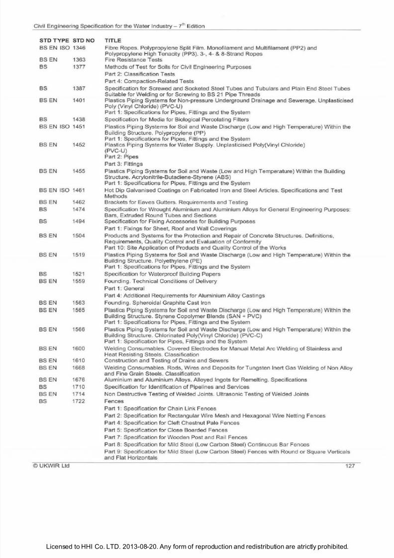
7/21/2019 The Civil Engineering Specification for the Water Industry 7th
http://slidepdf.com/reader/full/the-civil-engineering-specification-for-the-water-industry-7th 133/176Licensed to HHI Co. LTD. 2013-08-20. Any form of reproduction and redistribution are atrictly prohibited.
Civil Engineering Specification for the Water Industry - 7lh Edition
STD TYPE STD NO
BS EN ISO 1346
BSEN 1363
BS 1377
BS 1387
BSEN 1401
BS 1438
BS E N ISO 1451
BS EN
1452
BS
EN 1455
BS EN ISO 1461
BS EN 1462
BS 1474
BS 1494
BS EN
1504
BS EN 1519
BS 1521
BS E N 1559
BS EN 1563
BS EN
565
BS EN
1566
BS EN 1600
BS EN 1610
BS EN 1668
BS EN 1676
BS
1710
BS EN 1714
BS 1722
©
UKWIR
Ltd
TITLE
Fibre Ropes. Polypropylene Split Film. Monofilament and Multifilament (PP2) and
Polypropylene High Tenacity (PP3). 3-, 4-
8-Strand Ropes
Fire Resistance Tests
Methods of Test for Soils for Civil Engineering Purposes
Part 2: Classification Tests
Part 4: Compaction-Related Tests
Specification for Screwed and Socketed Steel Tubes and Tubulars and Plain End Steel Tubes
Suitable for Welding or for Screwing to BS 2 Pipe Threads
Plastics Piping Systems for Non-pressure Underground Drainage and Sewerage. Unplasticised
Poly (Vinyl Chloride) (PVC-U)
Part 1: Specifications for Pipes, Fittings and the System
Specification for Media for Biological Percolating Filters
Plastics Piping Systems for Soil and Waste Discharge (Low and High Temperature)
Wi
thin the
Building Structure. Polypropylene (PP)
Part 1: Specifications for Pipes, Fittings and the System
Plastics Piping Systems for Water Supply. Unplasticised Poly(V
in yl
Chloride)
(PVC-U)
Part 2: Pipes
Part 3: Fittings
Plastics Piping Systems
for
So
il
and Waste (Low and High Temperature) Within the Building
Structure. Acrylonitrile-Butadiene-Styrene (ABS)
Part 1: Specifications for Pipes, Fittings and the System
Hot Dip Galvanised Coatings on Fabricated Iron and Steel Articles. Specifications and Test
Methods
Brackets for Eaves Gutters. Requirements and Testing
Specification for Wrought Aluminium and Aluminium Alloys for General Engineering Purposes:
Bars, Extruded Round Tubes and Sections
Specification for Fixing Accessories for Building Purposes
Part 1: Fixings for Sheet, Roof and Wall Coverings
Products and Systems for the Protection and Repair of Concrete Structures. Definitions,
Requirements, Quality Control and Evaluation of Conformity
Part 10: Site Application of Products and Quality Control of the Works
Plastics Piping Systems for Soil and Waste Discharge (Low and High Temperature) Within the
Building Structure. Polyethylene (PE)
Part 1: Specificat ions for Pipes, Fittings and the System
Specification for Waterproo f Bu
il
ding Papers
Founding. Technical Conditions of Delivery
Part 1: General
Part 4: Additiona l Requirements for Aluminium A lloy Castings
Founding. Spheroidal Graphite Cas t Iron
Plastics Piping Systems for Soil and Waste Discharge
low
and High Temperature) Within the
Building Structure. Styrene Copolymer Blends SAN + PVC)
Part 1: Specifications for Pipes, Fittings and the System
Plastics Piping Systems for Soil and Waste Discharge (Low and High Temperature) Within the
Building Structure. Chlorinated Poly(Vinyl Chloride) (PVC-C)
Part 1: Specification for Pipes, Fittings and the System
Welding Consumables. Covered Electrodes for Manual Metal Arc Welding of Stainless and
Heat Resisting Steels. Classification
Construction and Testing of Drains and Sewers
Welding Consumables. Rods, Wires and Deposits for Tungsten Inert Gas Welding of Non Alloy
and Fine Grain Steels. Classification
Aluminium and Aluminium Alloys. Alloyed Ingots for Remelting. Specifications
Specification for Identification of Pipelines and Services
Non Destructive Testing of Welded Joints. Ultrasonic Testing of Welded Joints
Fences
Part : Specification for Chain Link Fences
Part 2: Specification for Rectangular Wire Mesh and Hexagonal Wire Netting Fences
Part 4: Specification for Cleft Chestnut Pale Fences
Part
5:
Specification for Close Boarded Fences
Part
7:
Specification for Wooden Post and Rail Fences
Part 8: Specification for Mild Steel (Low Carbon Steel) Continuous Bar Fences
Part
9:
Specification for Mild Steel
low
Carbon Steel) Fences with Round or Square Verticals
and Flat Horizontals
127
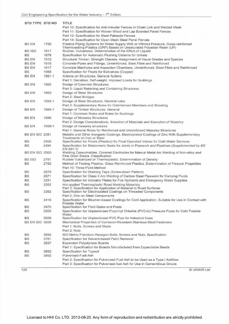
7/21/2019 The Civil Engineering Specification for the Water Industry 7th
http://slidepdf.com/reader/full/the-civil-engineering-specification-for-the-water-industry-7th 134/176Licensed to HHI Co. LTD. 2013-08-20. Any form of reproduction and redistribution are atrictly prohibited.
Civil Engineering Specification for the Water Industry i Edition
STD TYPE STD NO TITLE
BS EN 1796
BS ISO 1817
BS
1876
BS EN 1912
BSEN 1916
BSEN
1917
BS 1968
BS EN 1991 1
BS EN 1992
BSEN 1993
BS EN
1993-1
BS EN 1995-1
BS EN 1996
BS EN 1996-1
BS EN ISO 2081
BS
2456
BS 2494
BS EN ISO 2560
BS ISO 2781
BS 2782
BS
2879
BS 2971
BS 3251
BS 3262
BS 3382
BS 3416
BS 3470
BS 3505
BS 3506
BS EN ISO 3506
BS 3692
BS 3761
BS
3837
BS 3882
BS 3892
128
Part 10: Specification for Anti-Intruder Fences in Chain Link and Welded Mesh
Part 11
: Specification for Woven Wood and Lap Boarded Panel Fences
Part 12: Specification for Steel Palisade Fences
Part 14: Specification for Open Mesh Steel Panel Fences
Plastics Piping Systems for Water Supply With or Without Pressure. Glass-reinforced
Thermosetting Plastics GRP) Based on Unsaturated Polyester Resin UP)
Rubber, Vulcanized. Determination
of
the Effect
of
Liquids
Specification for Automatic Flushing Cisterns for Urinals
Structural Timber. Strength Classes. Assignment of Visual Grades and Species
Concrete Pipes and Fittings, Unreinforced, Steel Fibre and Reinforced
Concrete Manholes and Inspection Chambers, Unreinforced, Steel Fibre and Reinforced
Specification for Floats for Ballvalves Copper)
Actions
on
Structures.
General
Actions
Part 1: Densities, Self-weight, Imposed Loads for Bu
il
dings
Design
of Concrete Structures
Part
3:
Liquid Retaining and Containing Structures
Design of Steel Structures
Part 2: Steel Bridges
Design of Steel Structures. General rules
Part 3: Supplementary Rules for Cold-formed Members and Sheeting
Design
of
Timber Structures. General
Part 1: Common Rules and Rules for Buildings
Design of Masonry Structures
Part 2: Design Considerations, Selection
of
Materials and Execution
of
Masonry
Design
of
masonry structures
Part
1:
General Rules for Reinforced and Unreinforced Masonry Structures
Metallic and Other Inorganic Coatings. Electroplated Coatings
of
Zinc With Supplementary
Treatments on Iron
or
Steel
Specification for Floats Plastics) for Float Operated Valves for Cold Water Services
Specification for Elastomeric Seals for Joints in Pipework and Pipelines
Supplemented
by BS
N
681-1)
Welding Consumables. Covered Electrodes for Manual Metal Arc Welding
of
Non-alloy and
Fine Grain Steels. Classification
Rubber Vu lcanized or Thermoplastic. Determination of Density
Method ofTesting Plastics. Glass Reinforced Plastics. Determination
of
Flexural Properties
Part 10: Three Point Method
Specification for Draining Taps Screw-down Pattern)
Specification for Class
II
Arc Welding
of
Carbon Steel Pipework for Carrying Fluids
Specification for
Indicator
Plates for Fire Hydrants
and
Emergency Water Supplies
Hot-applied Thermoplastic Road Marking Materials
Part 3: Specification for Application of Material to Road Surfaces
Specification for Electroplated Coatings on Threaded Components
Part 2: Zinc on Steel Components
Specification for Bitumen-based Coatings for Cold Application, Suitable for Use in Contact with
Potable Water
Specification for Field Gates and Posts
Specification for Unplasticised Polyvinyl Chloride PVC-U) Pressure Pipes for Cold
Po
table
Water
Specification for Unplasticised PVC Pipe for Industrial Uses
Mechanical Properties
of
Corrosion-Resistant Stainless-Steel Fasteners
Part 1: Bolts, Screws and Studs
Part 2: Nuts
ISO Metric Precision Hexagon Bolts, Screws and Nuts. Specification
Specification for Solvent-based Paint Remover
Expanded Polystyrene Boards
Part 1: Specifi
ca tion for Boards Manufactured from Expandable Beads
Specificati
on
for Topso
il
Pulverised-Fuel Ash
Part
2:
Specification for Pulverized-Fuel Ash to be Used as a Type I Addition
Part 3: Specification for Pulverised-fuel Ash for Use in Cementitious Grouts
©UKWIR
Ltd
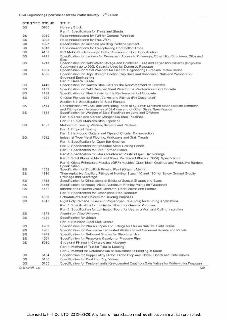
7/21/2019 The Civil Engineering Specification for the Water Industry 7th
http://slidepdf.com/reader/full/the-civil-engineering-specification-for-the-water-industry-7th 135/176
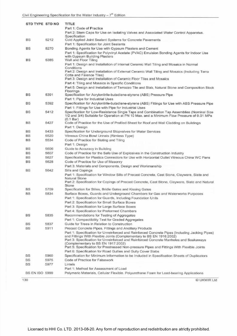
7/21/2019 The Civil Engineering Specification for the Water Industry 7th
http://slidepdf.com/reader/full/the-civil-engineering-specification-for-the-water-industry-7th 136/176Licensed to HHI Co. LTD. 2013-08-20. Any form of reproduction and redistribution are atrictly prohibited.
Civil Engineering Specification for the
Water
Industry- JhEdition
ST TYPE ST NO TITLE
BS
BS
BS
BS
BS
BS
BS
BS
BS
BS
BS
BS
BS
BS
BS
BS
BS
BS
BS
BS
BS
BS
BS
5212
5270
5385
5391
5392
5412
5427
5433
5520
5534
5606
5607
5627
5628
5642
5709
5834
5835
5837
5911
5960
5975
5977
BS EN ISO 5999
130
Part 1: Code
of Pr
actice
Part 2: Stem Caps for Use on Isolating Valves and Associated Water Control Apparatus.
Specification
Cold Applied
Jo
int Sealant Systems for Concrete Pavements
Part 1: Specification for Joint Sealants
Bonding Agents for Use with Gypsum Plasters and Cement
Part
1:
Specification for Polyvinyl Acetate PVAC) Emulsion Bonding Agents for Indoor Use
with Gypsum Building Plasters
Wall and Floor Ti l ing
Part
1:
Design
and
Installation
of
Internal Ceramic Wall Tiling and Mosaics in Normal
Conditions
Part 2: Design
and
Installation of External Ceramic Wall Tiling and Mosaics Including Terra
Cotta and
Faience
Tiles)
Part 3: Design and Installation of Ceramic Floor Tiles and Mosaics
Part
4:
Ti
li
ng
and
Mosaics in Specific Conditions
Part 5: Design and Installation of Terrazzo T ile and Slab, Natural Stone and Composition Block
Floorings
Specification
for
Acrylonitrile-butadiene-styrene ABS) Pressure Pipe
Part
1:
Pipe for Industrial Uses
Specification
for
Acrylonitrile-butadiene-styrene ASS) Fittings for Use with
ABS
Pressure Pipe
Part
1:
Fittings
for
Use with Pipe for Industrial Uses
Specification for L
ow
-Resistance Single Taps and Combination Tap Assemblies Nom inal Size
1/2 and 3/4) Suitab le for Operation at PN 10 Max. and a Minimum Flow Pressure of 0.01 MPa
0.1 Bar)
Code
of
Practice for
the
Use
of
Profiled
Sheet
for Roof and Wall Cladding
on
Buildings
Part 1: Design
Specification
for
Underground Stopvalves for Water Services
Vitreous China Bowl Urinals Rimless Type)
Code of Practice for Slating and Tiling
Part 1: Design
Guide to Accuracy in Building
Code of Practice for the Safe Use
of
Explosives in the Construction Industry
Specification
for
Plastics Connectors for Use with Horizontal Outlet Vitreous China
WC
Pans
Code of Practice for Use of Masonry
Part
3:
Materials and Components, Design and Workmanship
Sills and Copin
gs
Part
1:
Specification for Window Sills of Precast Concrete, Cast Stone, Clayware, Slate and
Natural Stone
Part
2:
Specification for Copings of Precast Concrete, Cast Stone, Clayware, Slate and Natural
Stone
Specification
for
Stiles, Bridle Gates and Kissing Gates
Surface Boxes, Guards and Underground Chambers for Gas and Waterworks Purposes
Part 1: Specification for Guards, Including Foundation Units
Part
2:
Spec
ification for Small Surface Boxes
Part
3:
Specification
for
Large Surface Boxes
Part
4:
Specification
for
Preformed Chambers
Recommendations for Testing of Aggregates
Part 1: Compactibility Test for Graded Aggregates
Guide for Trees in Relation to Construction
Precast Concrete Pipes, Fittings and Anci
ll
ary Products
Part
1:
Specification for Unreinforced and Reinforced Concrete Pipes Including
Jack
ing Pipes)
and Fittings With Flexible Joints Complementary to BS EN
1916:2002
Part 3: Specification for Unreinforced and Reinforced Concrete Manholes and Soakaways
Complementary to BS EN 1917 :2002
Part
5:
Specification for Prestressed Non-pressure Pipes and Fittings With Flexible Joints
Part 6: Specification for Road Gullies and Gully Cover Slabs
Specification for Minimum Information to
be
Included in Specification Sheets
of
Duplicators
Code
of
Practice for
Fa
lsework
Lintels
Part 1: Method for Assessment of Load
Polymeric Materials, Cellular Flexible. Polyurethane Foam for Load-bearing Applications
©UKWIR
Ltd
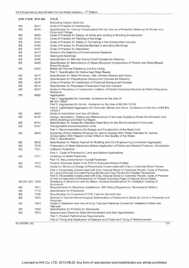
7/21/2019 The Civil Engineering Specification for the Water Industry 7th
http://slidepdf.com/reader/full/the-civil-engineering-specification-for-the-water-industry-7th 137/176Licensed to HHI Co. LTD. 2013-08-20. Any form of reproduction and redistribution are atrictly prohibited.
Civil
Eng
ineering Specification for the Water Industry 7lh Edition
STD
TYPE
STD
NO
BS 6031
BS 6076
BS 6093
BS 6150
BS 6164
BS 6180
BS 6187
BS 6213
BS 6262
BS 6398
BS 6446
BS 6452
BS 6510
BS 6515
BS 6576
BS 6610
BS 6657
PO 6682
BS 6683
BS
6700
BS 6744
BS
6767
BS 6920
BS 6925
BS 7079
BS 736
BS
7371
BS
7412
BS
7533
BS EN ISO 7599
BS
767
BS 7775
BS 7786
BS
7874
BS
7903
BS 7956
BS 7973
UKWIR Ltd
TITLE
Excluding Carpet Underlay
Code of Practice for Earthworks
Specification for Tubular Polyethylene Film for Use as a Protective Sleeving for Buried Iron
Pipes and Fittings
Code of Practice for Design of Joints and Jointing in Building Construction
Code of Practice for Painting
of
Buildings
Code
of
Practice for Safety in Tunnelling in the Construction Industry
Code of Practice for Protective Barriers in and about Bu
il
dings
Code
of
Practice for Demolition
Guide to the Selection of Constructional Sealants
Glazing for Buildings
Specification for Bitumen Damp-Proof Courses for Masonry
Specification for Manufacture
of
Glued Structural Components of Timber and Wood Based
Panel Products
Beads for Internal Plastering and Dry Lining
Part 1: Specification for Galvanised Steel Beads
Specification for Steel Windows, Sills, Window Boards and Doors
Specification for Polyethylene Damp-proof Courses for Masonry
Code
of
Practice for Installation
of
Chemical Damp-proof Courses
Specification for Pozzolanic Pulverised-Fu el Ash Cement
Guide
to
Prevention of Inadvertent Initiation
of
Electro-Explosive Devices by Radio-Frequency
Radiation
Aggregates.
Part 1: Aggregates for Concrete . Guidance on the Use of
BS EN 12620
Part 3: Aggregates for Mortar. Guidance on the Use
of BS EN 13139
Part 4: Lightweight Aggregates for Concrete, Mortar and Grout. Guidance on the Use of BS EN
13055-1
Guide to Installation and Use of Valves
Design, Installation, Testing and Maintenance
of
Services Supplying Water for Domest ic Use
Within Buildings and their Curtilages
Specification for Austenitic Stainless Steel Bars for the Reinforcement
of
Concrete
Transportable Accommodation Units
Part 1: Recommendations for Design and Construction
of
the Basic Unit
Suitab
il
ity of Non-Metallic Products for Use in Contact With Water Intended for Human
Consumption With Regard to their Effect on the Quality of the Water
Part 1: Specification
Specification for Mastic Asphalt for Building and Civil Engineering Limestone Aggregate)
Preparation
of
Steel Substrates Before Application
of
Paints and Related Products. Introduction
Cathodic Protection
Part 1: Code of Practice for Land and Marine Applications
Coatings on Metal Fasteners
Part 12: Requirements for Imperial Fasteners
Plastics Windows Made From PVC-U Extruded Hollow Profiles
Guide for Structural Design of Pavements Constructed with Clay or Concrete Block Pavers
Part 3: Pavements Constructed with Clay, Natural Stone
or
Concrete Pavers. Code of Practice
for Laying Precast Concrete Paving Blocks and Clay Pavers for Flexible Pavements
Part 4: Pavements Constructed with Clay, Natural Stone or Concrete Pavers. Code of Practice
for the Construction of Pavements of Precast Concrete Flags or Natural Stone Slabs
Anodising
of
Alu
min
ium and its Alloys. General Specifications
for
Oxidation Coating
of
Aluminium
Requirements
for
Electrical Installations. lEE Wiring Regulations. Seventeenth Edition
Specification for Penstocks
Specification for Unsintered PTFE Tape for General Use
Method
of
Test for Microbiological Deterioration of Elastomeric Seals for Joints in Pipework and
Pipelines
Guide to Selection and Use of Gully Tops and Manhole Covers for Installation Within the
Highway
Specification f
or
Primers for Woodwork
Spacers and Chairs for Steel Reinforcement and their Specification.
Part 1: Product Performance Requirements
Part 2: Fixing and Application of Spacers and Chairs and Tying of Reinforcement
13
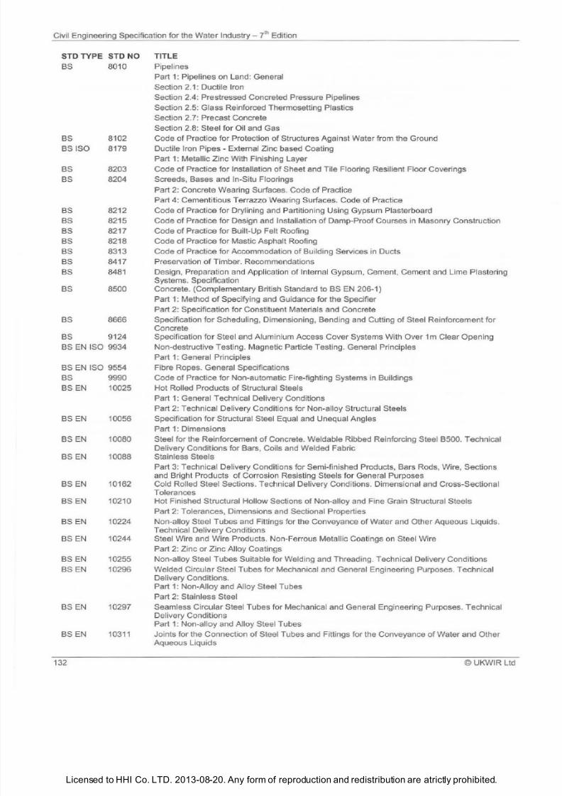
7/21/2019 The Civil Engineering Specification for the Water Industry 7th
http://slidepdf.com/reader/full/the-civil-engineering-specification-for-the-water-industry-7th 138/176Licensed to HHI Co. LTD. 2013-08-20. Any form of reproduction and redistribution are atrictly prohibited.
Civil Engineering Specification for the Water Industry
7th
Edition
ST TYPE ST NO
BS 8010
BS 8102
BS ISO 8179
BS 8203
BS 8204
BS 82 12
BS
8215
BS
8217
BS 8218
BS 8313
BS 8417
BS 8481
BS 8500
BS 8666
BS 9124
BS EN ISO 9934
BS EN ISO 9554
BS 9990
BS EN 10025
BS EN
10056
BS EN 10080
BS EN 10088
BS EN 10162
BS EN 10210
BSEN
10224
BS EN 10244
BSEN
10255
BSEN
10296
BS EN 10297
BSEN
10311
132
TITLE
Pipelines
Part 1: Pipelines on Land: General
Section 2.1: Ductile Iron
Section 2.4: Prestressed Concreted Pressure Pipelines
Section 2.5: Glass Reinforced Thermosetting Plastics
Section 2.7: Precast Concrete
Section 2.8: Steel for Oil and Gas
Code of Practice for Protection of Structures Against Water from the Ground
Ductile Iron Pipes - External Zinc based Coating
Part 1: Metallic Zinc With Finishing Layer
Code of Practice for Installation of Sheet and Tile Flooring Resilient Floor Coverings
Screeds, Bases and In-Situ Floorings
Part 2: Concrete Wearing Surfaces. Code of Practice
Part
4: Cementitious Terrazzo Wea
ri
ng Surfaces. Code of Practice
Code of Practice for Drylining and Partitioning Using Gypsum Plasterboard
Code of Practice for Design and Installation of Damp-Proof Courses in Masonry Construction
Code
of
Practice for Built-Up Felt Roofing
Code of Practice for Mastic Asphalt Roofing
Code
of
Practice for Accommodation
of
Building Services in Ducts
Preservation
of
Timber. Recommendations
Design, Preparation and Application of Internal Gypsum, Cement, Cement and Lim e Plastering
Systems. Specification
Concrete. Complementary British Standard to BS EN 206-1)
Part 1: Method of Specifying and Guidance for the Specifier
Part 2: Specification for Constituent Materials and Concrete
Specification for Scheduling, Dimensioning, Bending and Cutting
of
Steel Reinforcement for
Concrete
Specification for Steel and Aluminium Access Cover Systems With Over 1m Clear Opening
Non-destructive Testing. Magnetic Particle Testing. Genera l Principles
Part 1: General Principles
Fibre Ropes. General Specifications
Code
of
Practic€ for Non-automatic Fire-fighting Systems in Buildings
Hot Rolled Products
of
Structural Steels
Part 1: General Technical Delivery Conditions
Part 2: Technical Delivery Conditions for Non a lloy Structural Steels
Specification for Structural Steel Equal and Unequal Angles
Part 1: Dimensions
Steel for the Reinforcement
of Concrete. Weldable Ribbed Reinforcing Steel B500. Technical
Delivery Conditions for Bars, Coils and Welded Fabric
Stainless Steels
Part 3: Technical Delivery Conditions for Semi-finished Products, Bars Rods, Wire, Sections
and Bright Products
of
Corrosi
on
Resisting Steels for General Purposes
Cold Rolled Steel Sections. Technical Delivery Conditions. Dimensional and Cross-Sectional
Tolerances
Hot Finished Structural Hollow Sections
of
Non-alloy and Fine Grain Structural Steels
Part 2: Tolerances, Dimensions and Sectional Properties
Non-alloy Steel Tubes and Fittings for the Conveyance of Water and Other Aqueous Liquids.
Technical Delivery Conditions
Steel Wi
re
and Wire Products. Non-Ferrous Metal
li
c Coatings on Steel Wire
Part 2: Zinc
or
Zinc Alloy Coatings
Non-alloy Steel Tubes Suitable for Welding and Threading. Technical Delivery Conditions
Welded Circular Steel Tubes for Mechanical and General Engineering Purposes. Technical
Delivery Conditions.
Part 1: Non-Alloy and Alloy Steel Tubes
Part 2: Stainless Steel
Seamless Circul
ar
Steel Tubes for Mechanical and General Engineering Purposes. Technical
Delivery Conditions
Part 1: Non-alloy and Alloy Steel Tubes
Joints for the Connection
of
Steel Tubes and Fittings for the Conveyance of Water and Other
Aqueous Liquids
©UKWIR
l td
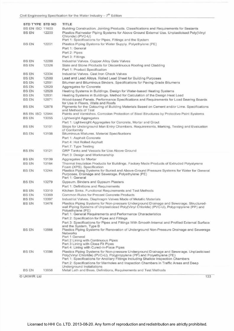
7/21/2019 The Civil Engineering Specification for the Water Industry 7th
http://slidepdf.com/reader/full/the-civil-engineering-specification-for-the-water-industry-7th 139/176Licensed to HHI Co. LTD. 2013-08-20. Any form of reproduction and redistribution are atrictly prohibited.
Civil Engineering Specification for the Water
Industry Jh
Edition
STD
TYPE STD NO
BS
EN
ISO 116
BS
EN
122
BS
EN
122 1
BS EN 12288
BS EN 12326
BS EN 12334
BS EN 12588
BS EN 12591
BS
EN 1262
BS EN 12828
BS EN 12831
BS EN 12871
BSEN 12878
BS EN ISO
12944
BS
EN 13 55
BS EN
131 1
BS EN 131 8
BSEN 13121
BSEN
13139
BS EN 13164
BS EN
13244
BS EN 13279
BSEN 1331
BS EN
13369
BS EN
13397
BS
EN
13476
BSEN 13566
BS EN 13598
BSEN 13658
© UKWIR Ltd
TITLE
Building Construction. Jointing Products . Classifications and Requirements for Sealants
Plastics Rainwater Piping Systems for Above Ground External Use. Unplasticised Poly Vinyl
Chloride) PVC-U)
Part 1: Specifications for Pipes, Fittings and the System
Plastics Piping Systems for Water Supply.
Po
lyethylene PE)
Part
1:
General
Part 2: Pipes
Part 3: Fittings
Industrial Valves. Copper Alloy Gate Valves
Slate and Stone Products for Discontinuous Roofing and Cladding
Part 1: Product Specification
Industrial Valves. Cast Iron Check Valves
Lead and Lead Alloys. Rolled Lead Sheet for Building Purposes
Bitumen and Bituminous Binders. Specifications for Paving Grade Bitumens
Aggregates for Concrete
Heating Systems
in
Buildings. Design for Water-based Heating Systems
Heating Systems in Buildings. Method for Calculation of the Design Heat Load
Wood-based Panels. Performance Specifications and Requirements for Load Bearing Boards
for Use in Floors , Walls and Roofs
Pigments for the Colouring of Building Materials Based on Cement and/or Lime. Specifications
and Methods of Test
Paints and Varnishes. Corrosion Protection of Steel Structures by Protective Paint Systems
Lightweight Aggregates
Part
1:
Lightweight Aggregates for Concrete, Mortar and Grout
Steps for Underground Man Entry Chambers. Requirements, Marking, Testing and Evaluation
of Conformity
Bituminous Mixtures. Material Specifications
Part 1: Asphalt Concrete
Part 4: Hot Rolled Asphalt
Part
7:
Type Testing
GRP Tanks and Vessels for Use Above Ground
Part 3: Design and Workmanship
Aggregates for Mortar
Thermal Insulation Products for Buildings. Factory Made Products of Extruded Polystyrene
Foam XPS). Specification
Plastics Piping Systems for Buried and Above-Ground Pressure Systems for Water for General
Purposes, Drainage and Sewerage.
Po
lyethylene PE)
Part 1: General
Gypsum. Binders and Gypsum Plasters
Part
1:
Definitions and Requirements
Kitchen Sinks . Functional Requirements and Test Methods
Common Rules for Precast Concrete Products
Industrial Valves. Diaphragm Valves Made of Metallic Materials
Plastics Piping Systems for Non-pressure Underground Drainage and Sewerage. Structured
wall Piping Systems of Unplasticized Poly Vinyl Chloride) PVC-U), Polypropylene PP) and
Polyethylene PE)
Part
1:
General Requirements and Performance Characteristics
Part 2: Specification for Pipes and Fittings
Part 3: Specifications for Pipes and Fittings With Smooth Internal and Profiled External Surface
and the System, Type B
Plastics Piping Systems for Renovation of Underground Non-Pressure Drainage and Sewerage
Networks
Part
1
General
Part
2
Lining with Continuous Pipes
Part 3 Lining with Close Fit Pipes
Part 4: Lining with Cured-in-Place Pipes
Plastics Piping Systems for Non-pressure Underground Drainage and Sewerage. Unplasticised
Poly Vinyl Chloride) PVC-U) ,
Po
lypropylene PP) and Polyethylene PE)
Part 1: Specifications for Ancillary Fittings Including Shallow Inspection Chambers
Part 2: Specifications for Manholes and Inspection Chambers in Traffic Areas and
Deep
Underground Installations
Metal Lath and Seas. Definitions , Requirements and Test Methods
133
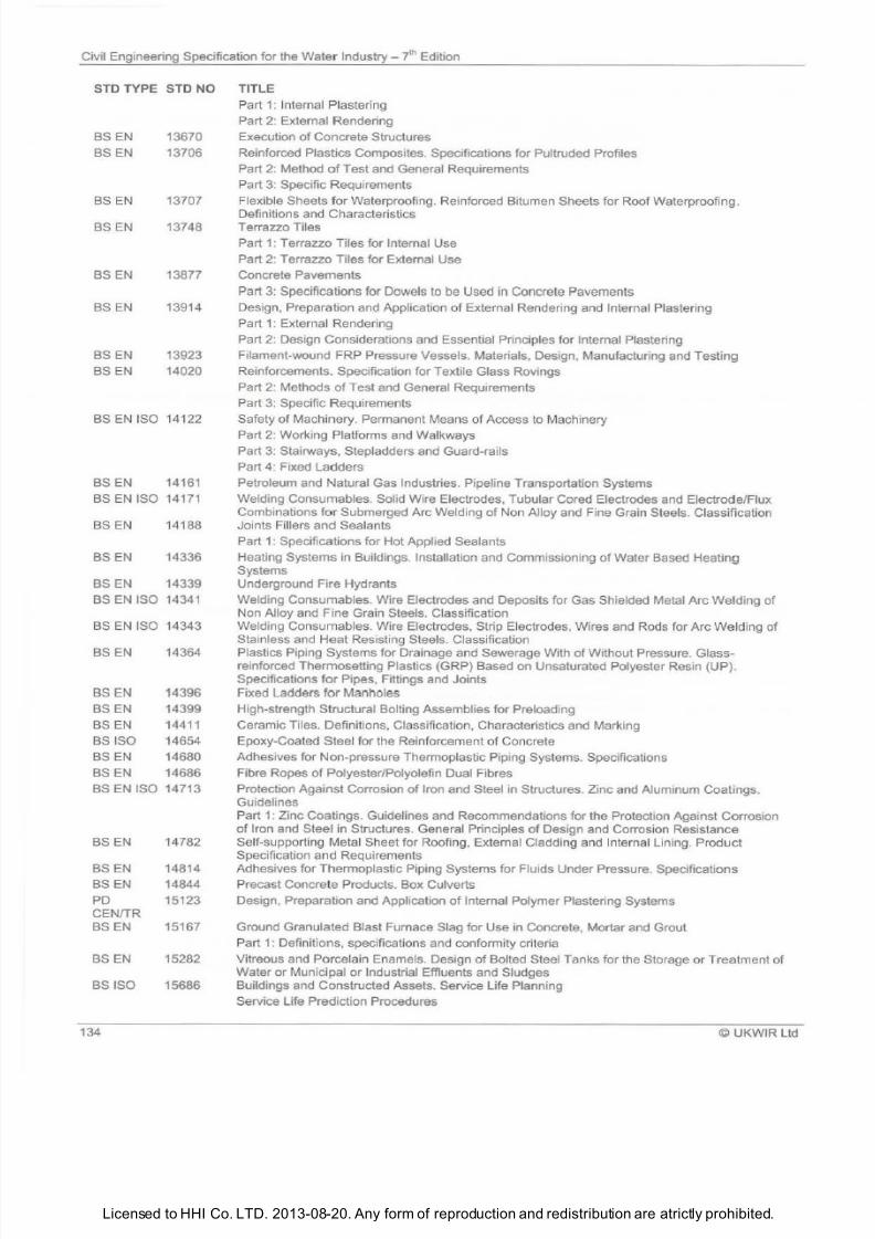
7/21/2019 The Civil Engineering Specification for the Water Industry 7th
http://slidepdf.com/reader/full/the-civil-engineering-specification-for-the-water-industry-7th 140/176Licensed to HHI Co. LTD. 2013-08-20. Any form of reproduction and redistribution are atrictly prohibited.
Civil Engineering Specification for the Water Industry
th
Edition
STD TYPE STD NO TITLE
BSEN 13670
BSEN
13706
BS EN 13707
BS EN 13748
BS EN 13877
BS EN 13914
BS EN 13923
BSEN
14020
BS EN ISO 14122
BSEN 14161
BS EN ISO 14171
BSEN
14188
BSEN 14336
BSEN
14339
BS EN ISO 14341
BS EN ISO 14343
BS EN
14364
BS EN 4396
BS EN 14399
BS EN 14411
BS ISO 14654
BS EN 14680
BSEN 14686
BS EN ISO 14713
BS EN 14782
BS EN 14814
BS EN 14844
PO 15123
CEN/TR
BS EN 15167
BS EN 15282
BSISO
15686
134
Part 1: Internal Plastering
Part 2: External Rendering
Execution
of
Concrete Structures
Reinforced Plastics Composites. Specifications for Pultruded Profiles
Part
2:
Method
of
Test and General Requirements
Part 3: Specific Requirements
Flexible Sheets for Waterproofing. Reinforced Bitumen Sheets for Roof Waterproofing.
Definitions and Characteristics
Terrazzo Tiles
Part 1: Terrazzo Tiles for Internal Use
Part 2: Terrazzo Tiles for External Use
Concrete Pavements
Part 3: Specifications for Dowels to be Used in Concrete Pavements
Design, Preparation and Application of External Rendering and Internal Plastering
Part 1: External Rendering
Part 2: Design Considerations and Essential Principles for Internal Plastering
Filament-wound FRP Pressure Vessels. Materials, Design, Manufacturing and Testing
Reinforcements. Specification for Textile Glass Ravings
Part 2: Methods
of
Test and General Requirements
Part 3: Specific Requirements
Safety
of
Machinery. Permanent Means
of
Access to Machinery
Part 2: Working Platforms and Walkways
Part 3: Stairways, Stepladders and Guard-rails
Part 4: Fixed Ladders
Petroleum and Natural Gas Industries. Pipeline Transportation Systems
Welding Consumables. Solid Wire Electrodes, Tubular Cored Electrodes and Electrode/Flux
Combinations for Submerged Arc Welding
of
Non Alloy and Fine Grain Steels. Classification
Joints Fillers and Sealants
Part 1: Specifications for Hot Applied Sealants
Heating Systems in Buildings. Installation and Commissioning of Water Based Heating
Systems
Underground Fire Hydrants
Welding Consumables. Wire Electrodes and Deposits for Gas Shielded Metal Arc Welding of
Non Alloy and Fine Grain Steels. Classification
Welding Consumables. Wire Electrodes, Strip Electrodes, Wires and Rods for Arc Weld ing of
Stainless and Heat Resisting Steels. Classification
Plastics Piping Systems for Drainage and Sewerage With of Without Pressure. Glass
reinforced Thermosetting Plastics GRP) Based on Unsaturated Polyester Resin UP).
Specifications for Pipes, Fittings and Joints
Fixed Ladders for Manholes
High-strength Structural Bolting Assemblies for Preloading
Ceramic Tiles. Definitions, Classification, Characteristics and Marking
Epoxy-Coated Steel for the Reinforcement of Concrete
Adhesives for Non-pressure Thermoplastic Piping Systems. Specifications
Fibre Ropes
of
Polyester/Polyolefin Dual Fibres
Protection Against Corrosion
of
Iron and Steel in Structures. Zinc and Aluminum Coatings.
Guidelines
Part 1: Zinc Coatings. Guidelines and Recommendations for the Protection Against Corrosion
of
Iron and Steel in Structures. General Principles
of
Design and Corrosion Resistanc€
Self-supporting Metal Sheet for Roofing, External Cladding and Internal Lining. Product
Specification and Requirements
Adhesives for Thermoplastic Piping Systems for Fluids Under Pressure. Specifications
Precast Concrete Products. Box Culverts
Design, Preparation and Application
of
Internal Polymer Plastering Systems
Ground Granulated Blast Furnace Slag for Use in Concrete, Mortar and Grout
Part
:
Definitions, specifications and conformity criteria
Vitreous and Porcelain Enamels. Design
of
Bolted Steel Tanks for the Storage
or
Treatment
of
Water or Municipal or Industrial Effluents and Sludges
Buildings and Constructed Assets. Service Life Planning
Service Life Prediction Procedures
UKWIR Ltd
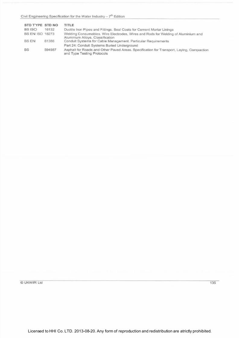
7/21/2019 The Civil Engineering Specification for the Water Industry 7th
http://slidepdf.com/reader/full/the-civil-engineering-specification-for-the-water-industry-7th 141/176Licensed to HHI Co. LTD. 2013-08-20. Any form of reproduction and redistribution are atrictly prohibited.
Civil Engineering Specificati
o
for the Water Industry ? h Edition
ST TYP ST NO
BSISO
16132
BS
EN
ISO 18273
BS EN
61386
BS 594987
UKWIR Ltd
TITLE
Ductile Iron Pipes and Fittings. Seal Coats for Cement Mortar Linings
Welding Consumables. Wire Electrodes Wires and Rods for Welding
of
Aluminium and
Aluminium Alloys. Classification
Conduit Systems for Cable Management. Particular Requirements
Part 24: Conduit Systems Buried Underground
Asphalt for Roads and Other Paved Areas. Specification for Transport Laying Compaction
and Type Testing Protocols
135

7/21/2019 The Civil Engineering Specification for the Water Industry 7th
http://slidepdf.com/reader/full/the-civil-engineering-specification-for-the-water-industry-7th 142/176Licensed to HHI Co. LTD. 2013-08-20. Any form of reproduction and redistribution are atrictly prohibited.
ivil Engineering Specification for the Water
Industry
yl Edition
36 ©UKWIR
Ltd
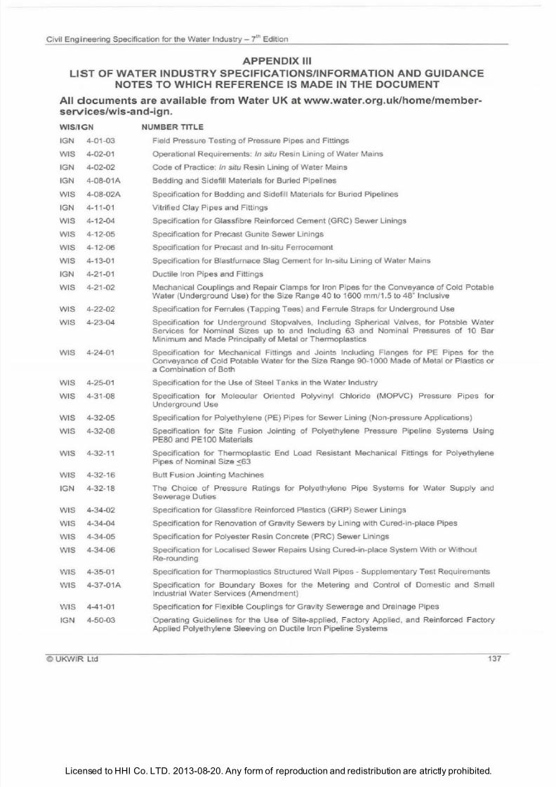
7/21/2019 The Civil Engineering Specification for the Water Industry 7th
http://slidepdf.com/reader/full/the-civil-engineering-specification-for-the-water-industry-7th 143/176
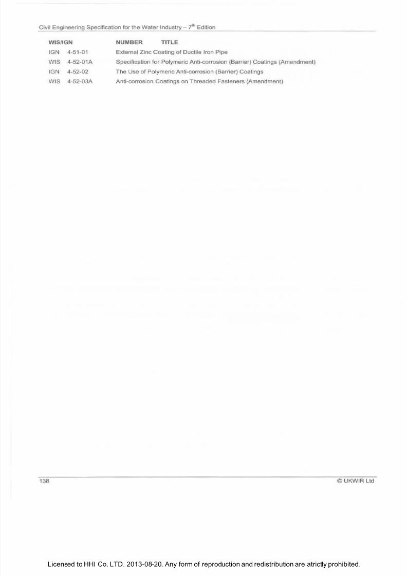
7/21/2019 The Civil Engineering Specification for the Water Industry 7th
http://slidepdf.com/reader/full/the-civil-engineering-specification-for-the-water-industry-7th 144/176Licensed to HHI Co. LTD. 2013-08-20. Any form of reproduction and redistribution are atrictly prohibited.
Civil Engineering Specification for the Water
Industry
?hEdition
WIS IGN
IGN 4-51-01
WIS 4-52-01A
IGN 4-52-02
WIS 4-52-03A
138
NUMBER TITLE
External Zinc Coating
of
Ductile Iron Pipe
Specification for Polymeric Anti-corrosion Barrier) Coatings Amendment)
The Use
of
Polymeric Anti-corrosi
on
Barrier) Coatings
Anti-corrosion Coatings on Threaded Fasteners Amendment)
©UKWIR Ltd
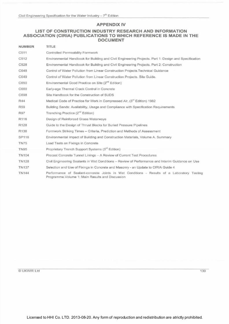
7/21/2019 The Civil Engineering Specification for the Water Industry 7th
http://slidepdf.com/reader/full/the-civil-engineering-specification-for-the-water-industry-7th 145/176Licensed to HHI Co. LTD. 2013-08-20. Any form of reproduction and redistribution are atrictly prohibited.
Civil Engineering Specification for the Water
Industry i
Edition
APPENDIX IV
LIST OF CONSTRUCTION INDUSTRY RESEARCH AND INFORMATION
ASSOCIATION CIRIA) PUBLICATIONS TO WHICH REFERENCE IS MADE N THE
DOCUMENT
NU
MBER
C511
C512
C528
C648
C649
C650
C660
C698
R44
R59
R97
R116
R128
R136
SP116
TN75
TN95
TN104
TN128
TN137
TN144
©
UKWIR Ltd
TITLE
Controlled Permeability Formwork
Environmental Handbook for Building and Civil Engineering Projects. Part 1: Design and Specification
Environmental Handbook for Building and Civil Engineering Projects. Part 2: Construction
Control
of
Water Pollution from Linear Construction Projects.Technical Guidance
Control
of
Water Pollution from Linear Construction Projects. Site Guide.
Environmental Good Practice on Site (2 d Edition)
Early-age Thermal Crack Control in Concrete
Site Handbook for the Construction of SUDS
Medical Code
of
Practice for Work in Compressed
Air
, 3
r
Edition) 1982
Building Sands: Availability, Usage and Compliance with Specification Requirements
Trenching Practice 2
n
Edition)
Design of Reinforced Grass Waterways
Guide
to
the Design
of
Thrust Blocks for Buried Pressure Pipelines
Formwork Striking
Times
Criteria, Prediction and Methods of Assessment
Environmental Impact of Building and Construction Materials, Volume A. Summary
Load Tests
on
Fixings in Concrete
Proprietary Trench Support Systems 3
r
Edition)
Precast Concrete Tunnel Linings
A
Review of Current Test Procedures
Civil Engineering Sealants in Wet Conditions - Review of Performance and Interim Guidance on Use
Selection and Use of Fixings in Concrete and Masonry- an Update
to
CIRIA Guide 4
Performance of Sealant-concrete Joints in
Wet
Conditions - Results of a Laboratory Testing
Programme Volume 1: Main Results and Discussion
139

7/21/2019 The Civil Engineering Specification for the Water Industry 7th
http://slidepdf.com/reader/full/the-civil-engineering-specification-for-the-water-industry-7th 146/176Licensed to HHI Co. LTD. 2013-08-20. Any form of reproduction and redistribution are atrictly prohibited.
ivilEngineering Specification for the Water
ndustry
th Edition
14
UKWIR
Ltd
7/21/2019 The Civil Engineering Specification for the Water Industry 7th
http://slidepdf.com/reader/full/the-civil-engineering-specification-for-the-water-industry-7th 147/176Licensed to HHI Co. LTD. 2013-08-20. Any form of reproduction and redistribution are atrictly prohibited.
Civil Engineering Specification for the Water Industry J h Edition
PPENDIX V
LIST OF ST TUTORY REFERENCES N THE DOCUMENT
Building Regulations 2000
Construction General Provisions) Regulations
1961
Construction Health, Safety and Welfare) Regulations 1996
Construction Health, Safety and Welfare) Regulations Northern Ireland) 1996
Construction Metrication) Regulations 1984
Control of
Asbestos Regulations 2006
Control of Asbestos Regulations Northern Ireland) 2007
Control
of
Explosives Regulations
1991
Control of Pollution O
il
Storage) England) Regulations 2001
Control of Pollution Oil Storage) Regulations Northern Ireland) 2010
Council Directive on the Approximation
of
Laws, Regulations and Administrative Provisions
of
the Member States
Relating
to
Construction Products 89/106/EEC)
Council Directive on the Procurement Procedures of Entities in the Water, Energy, Transport and Telecommunications
Sectors 93/38/EEC)
Dangerous Substances and Explosive Atmospheres Regulations 2002
Dangerous Substances and Explosive Atmospheres Regulations Northern Ireland) 2003
Environme
ntal Protection Act 1990 amended by Environment Act 1995)
Explosiv
es
Acts 1875 and 1923
Financing Act 1996 Landfill Tax), amended by the Finance Act 1999 and subsequent updates)
Hedgerows Regulations 1997
Land Drainage Act 1994
Manual Handling Operations Regulations 1992
New Roads and Street Works Act 1991
Petrol
eum
Consolidation) Act 1928
Petroleum Consolidation) Act Northern Ireland) 1929
Petroleum Spirit Motor Vehicles etc.) Regulations 1929
Planning Control
of
Major-accident Hazards) Regulations 2009
Planning Control of Major-accident Hazards) Regulations Northern Ireland) 2009
Planning Control
of
Major-accident Hazards) Scotland) Regulations 2009
Planning Hazardous Substances) Regulations 1992
Planning Hazardous Substances) Amendment) England) Regulations 2009
Planning Hazardous Substances) Amendment) Regulations Northern Ireland) 2005
Salmon and Fresh Water Fisheries Act 1975
Scottish Water Byelaws 2004)
Site Waste Management Plan Regulations 2008
Street Works Northern Ireland) Order 1995 and amendments
Town and Country Planning Hazardous Substances) Scotland) Regulations 1993
Traffic Management Act 2004 and Orders for England and Wales)
Traffic Signs Regulations and General Directions 2002
Utilities Directive on the Procurement Procedures of Entities Operating in the Water, Energy, Transport and Postal
Services Sectors 2004/17/EC)
Water Resources Act 1991
Water Supply Water Fittings) Regulations Northern Ireland) 2009
©UKWIR Ltd
141
7/21/2019 The Civil Engineering Specification for the Water Industry 7th
http://slidepdf.com/reader/full/the-civil-engineering-specification-for-the-water-industry-7th 148/176
7/21/2019 The Civil Engineering Specification for the Water Industry 7th
http://slidepdf.com/reader/full/the-civil-engineering-specification-for-the-water-industry-7th 149/176Licensed to HHI Co. LTD. 2013-08-20. Any form of reproduction and redistribution are atrictly prohibited.
Civil Engineering Specification for the Water Industry 7
h Edition
PPENDIX VI
LIST OF OTHER PUBLIC TIONS TO WHICH REFERENCE IS M DE N
TH
DOCUMENT
Al
ka li-S il
i
ca
Reaction, Digest 330, 1999. Bu
il
ding Research Establishment (BRE), Bucknalls Lane, Garston, Watford, WD2
7JR
ASTM D3575.-00e1 American Society f
or
Tes
ting Materials, 1916 Race Street, Philadelphia, PA 19103, USA
Avoiding Danger from Underground Services, HSG 47, HSE, PO Box 1999, Sudbury, Suffolk, C010 6FS
Bricklaying in Winter Conditions. Brick Development Association
Chamber Tops and Gully Tops for Road Drainage and Services: Installation and Maintenance, 2009. HA 104/09. Highways
Agency
Concrete in Aggressive Ground, Special Digest No. 1, 2005. Building Research Establishment, Bucknalls Lane, Garston,
Watford, WD2 7
JR
Damage Control Procedures for Pipeline Construction Involving Pipe Spli tting. UKWIR/British Gas (Currently Transco).
UKWIR Ltd, 1 Queen Anne s Gate, London, SW1 H 9BT
Every
Drop
Counts - Keeping Water Clean. Crop Protection Association, 4 Lincoln Court, Lincoln Road, Peterborough, PE1
2RP (available at http://www.voluntaryinitiative.org.uki_Attachments/Resources/978_S4.pdf)
Foamed Concrete - A Specification for Use in Reinstatement of Openings in Highways. British Cement Association, Century
House, Telford Avenue, Crowthorne, Berkshire, RG11 6YS
Guidance for the Design
of
Steel Fibre Reinforced Concrete. Technical Report 63. The Concrete Society, Riverside House,
4 Meadows Business Park, Station Approach, Blackwater, Camberley, Surrey, GU17 9AB
Guidance
for
the Selection
of
Water Supply Pipes to be used In Brownfield Sites. UKWIR Ltd, 1 Queen Anne s Gate,
London, SW 1H 9BT
Guide to Best Practice for the Installation
of
Pipejacks and Microtunnel
s.
Pipe Jacking Association, Hamilton House, 1
Temple Avenue, London, EC4Y
OHA
Guide to Site Practice. Box Culvert Association, 60 Charles Street, Leicester LE1 1FB
Guidel ines for the Planning, Installation and Maintenance of Utility Services in Proximity to Trees, NJUG Publication No.10,
1995. National Joint Utilities Group, 30 Millbank, London, SW1 P 4RD
Hardcore, Digest 276. Building Research Establishment (BRE), Bucknalls Lane, Garston, Watford, WD2 7JR
Horizontal Directional Drilling Good Practice Guidelines (3 dEdition). North American Society for Trenchless Technology
In-situ Cement Mortar Lining -Operational Guidelines and Code
of
Practice. WRc pic Frankland Road, Blagrove, Swindon,
Wiltshire, SN5 BYF
Leaving Decommissioned Asbestos Pipes in Excavations. Environment Agency (available at http://environment
agency.co.uk)
Model Consultative Procedure for Pipeline Construction Involving Deep Excavation, 1993. British Gas/WSAIWCA, Ashby
Road, Loughborough, LE11 3GR
Model Contract Document for Sewer Condition Inspection, WSA and FWR, 1994. WRc pic, Frankland Road, Blagrove,
Swindon, Wiltshire, SN5 8YF
National Structural Steelwork Specification for Building Construction , 2009. British Constructional Steelwork Association
Occupational Exposure Limits, Guidance Note EH40, 2002 plus supplement 2003. HSE, PO Box 1999, Sudbury, Suffolk,
C010 6FS
Pollution Prevention Guidance Notes. Environment Agency (available at www.environment-agency.gov.uk)
Pollution Prevention Guidelines PPG2 and PPG 26)
Polyethylene Pipe Systems Manual. WRc pic/ BPF (available at www.wrcplc.co.uklpe)
Principles of Water Supply Hygiene: Technical Guidance Notes, 2010. Water UK/Royal Society for Public Health (available
at www.water.org.uk)
Procedures for Testing the Capability
of
Cured In Place Pipe (CIPP) Lining Systems to Resist Infiltration, Report CP308.
WRc pic, Frankland Road, Blagrove, Swindon, Wiltshire, SN5 BYF
Requirements for Electrical Installations, BS 7671: 2001. Institution of Electrical Engineers, Savoy Place, London, WC2R
OBL
Safety at Street Works and Road Works, 2002. The Stationery Office Ltd, PO Box 276, London,
SWB SOT
Specification for Portable Traffic Signal Control Equipment for Use at Roadworks TR 2502
© UKWIR Ltd 143
7/21/2019 The Civil Engineering Specification for the Water Industry 7th
http://slidepdf.com/reader/full/the-civil-engineering-specification-for-the-water-industry-7th 150/176Licensed to HHI Co. LTD. 2013-08-20. Any form of reproduction and redistribution are atrictly prohibited.
Civil Engineering Specification for the Water Industry - 7 h Edition
Specification for the Reinstatement of Openings in Highways. Department for Transport available at www.dft.gov.uk)
Specification for the Reinstatement of Openings in Highways (2 d Edition)
Specification for the Reinstatement
of
Openings in Roads.The Scottish Government available at www.scotland.gov .uk)
Specification for Tunnelling. British Tunnelling Society/ Institution
of
Civil Engineers
Sewerage Rehabilitation Manual 5
h Edition), 2001. WRc pic available at http://srm.wrcplc.co.uk)
Sliplining and Replacement Moling
of
Water Mains Operational Guidelines. WRc pic, Frankland Road, Blagrove, Swindon,
Wiltshire, SN5 8YF
Specification for Highway Works. Highways Agency, 123 Buckingham Palace Road, London, SW1W 9HA
Specification for Piling and Embedded Retaining Walls. Institution
of
Civil Engineers, 1-7 Great George Street, London,
SW1P 3AA
Specification for Tunnelling. British Tunnelling Society and Institution of Civil Engineers, 1-7 Great George Street, London,
SW1P 3AA
The Management
of
Asbestos in Non-domestic Premises, Regulation 4
of
the Control
of
Asbestos Regulations 2006. Heal
th
and Safety Executive available at www.hse.gov.uk)
Traffic Signs Manual. Department
of
Transport, The Stationery Office Ltd, PO Box 276, London, SW8 SDT
Traffic Signs Regulations and General Directions, 2002. The Stationery Office Ltd, PO Box 276, London, SW8 SOT
Typical Specifications for Trenchless Technology Systems, UM 1464, 1995
Water Fittings and Materials Directory www.wras.co.uk/directory)
Water Mains Rehabi litation Manual, 1989.
WRc
pic, Frankland Road, Blagrove, Swindon, Wiltshire, SN5 8YF
Winter Concreting and Technical Guidance Notes, 1985. Concrete Information Ltd, Century House, Telford Avenue,
Crowthorne, Berkshire, RG11 6Y
Work with Materials Containing Asbestos. Control
of
Asbestos Regulations 2006. Health and Safety Executive available at
www.hse.gov.uk)
144
©U
KWIR Ltd
7/21/2019 The Civil Engineering Specification for the Water Industry 7th
http://slidepdf.com/reader/full/the-civil-engineering-specification-for-the-water-industry-7th 151/176Licensed to HHI Co. LTD. 2013-08-20. Any form of reproduction and redistribution are atrictly prohibited.
Civil Engineering Specification for the Water Industry
i
Edition
IN EX TO SPECIFIC TION
Clause
Abandoning sewers and manholes .............•...............................................................................5.23
Access to
properties and apparatus, interference with .......................................................................... 1.11
the works ................................................. ..... ........................................................................ 1.43
Accommodation
Contract Administrator s ........................................................................................................ 1.2
for
the
Contract ..................................................................................................................... 1.2
Acrylonitrile-butadiene-styrene (ABS) pipes and fittings ............................................................. 2.2
Adhesives, synthetic resin for timber .......................................................................................... 2.125
Admixtures
containing calcium chloride ..... ....... ......................................................................... .............. 2.3.2
for concrete or grout ............................
..
.................
..
............................................................. 2.3, 2.17 2
restrictions
on
use .................................................................................................................2.22(iv)
Advertising
billposting and ... .................................................................................................................... 1.3
consent for .............................................................................................................. ........... ... 1 3(i)
Aggregates
for concrete .................................................................. ......................................................... 2.4, 2.4(iii), 2.20(i), 2.20(ii) ,
.............................................................. ................................................................................ 4.6.1
for high strength concrete wearing screeds .......................................................................... 2.5
for mortar ............................................................................................................ .................. 2.6
mineral, for flat roofs .................................................. ................................................................. 2.81
recycled, use of ................................................. ................................................................... 2.4.3, 2.4.4
restrictions on source, type or group ................................................................... .................. 2.4(i)
Agricultura l land
fertiliser for ........................................................................................................................... 2.39
grass seed for ....................................................................................................................... 2.55
protection of, use of herbicides and pesticides ..................................................................... 1.14
reinstatement
of
......................................... ........................................................................... 3.9.3
Air
bricks ..................................................................................................................................... 2.14(ii), 2.14.4
Air-entrained concrete ................................................................................................................. 2.24, 4.27.1
Air test
for non-pressure pipelines ..................................................................................................... 7.6
localised .................. ............................................ ....................................................... ........... 9.11.3
Alkali-silica reaction ..................................... .........
..
........... .. ............................. ........................... 2.20(v)
Alternate bay const
ru
ction, concrete
..
..... .................................................................................... 4.5(i)
Aluminium and aluminium alloy
for gutters and pipes ............................................................................................................. 2.1 12(i), 2.112(ii)
for handrails ................ ... ................................. ...................................................................... 2.60.2, 2.60.5, 2.60(iv)
for steps ................................................. .... ............................................................ ...............2.75(ii)
for welding............................................................................................................................. 2.37.4
for windows ........................................................................................................................... 2.138.1
for wrought ladders ............................................................................................................... 2.70.5
wrought ....................................................................... .......................................................... 2.142
Annulus grouting, generally ............... ......................................................................................... 9.8
Apparatus, and properties
diversions and programme
of
Works ......................................................................... ............ 1.17.2
interference with access .......................................................................................................1.11
of
Statutory Undertakers, Highway
or
Road Authority and others ......................................... 1.17
replacement of ....... ................................................................... ........................................... 1.13.3
supporting
and
working round ................................................. .............................................. 1.13.2
Areas of restricted operations ..................................................................................................... 1.16(iii)
Asphalt, mastic .................................. ..........................................................................................2.77
hot roll
ed
laying ...... ....................................................... ................................... ..................
..
8.6
rolled .................................................................................................. ...................................2.1 13
roofing ............................................ ........................... .... .................................................. ...... 2.81, 6.29
Asphalt concrete ........................................... .............................................................................. 2.7
UKWIR Ltd 145
7/21/2019 The Civil Engineering Specification for the Water Industry 7th
http://slidepdf.com/reader/full/the-civil-engineering-specification-for-the-water-industry-7th 152/176Licensed to HHI Co. LTD. 2013-08-20. Any form of reproduction and redistribution are atrictly prohibited.
Civil Engineering Specification for the Water
Industry
J h Edition
Asset records .............................................................................................................................. 1.23, 5.22.3, 5.25.2, 5.33.3,
.............................................................................................................................................. 5.33.4
Backfilling
around mains and services .................... ........................................................
..
..... ................ 3.6 i)
for ductile iron, cast iron and steel pipes, flanges and fittings ............................................... 2.36.8
generally ............. ........................................................................................................................ 3.6
in streets .......................... ........................... .... ...................................................
..
....................... 3.6.4
materials ............................................................................................................................... 3.6 11)
removal of supports .............................................................................................................. 3.6.5
timing of .................................................................................................. ............................. 3.6.1
to
water retaining structures ................................................................................................. 3.6 v)
under land drains .................................................................................................................. 3.12.3
Balusters and handrails ......................................................................................... ...... ............... 2.60
Battered sides to excavations .....................................................................................................
3.1
v)
Beads
expandable ................................................................................................................ ........... 2.12.1
expanded metal angle .......................................................................................................... 2.38,
6.1
0.3, 6.12. 5
Bedding, pipe .............................................................................................................................. 2.55 iii), 2.90.1, 3.5.3, 5.1,
.............................................................................................................................................. 5.2
Bedding and sidefill material, pipe .............................................................................................. 2.88.1
Benchings, inverts and manhole....................... .. .... .................................................................... 5.18
Bench marks, temporary ........................................................................................ ..................... 1.8.1
Bill posting and advertising .......................................................................................................... 1.3
Biological percolating filter media ............................................................................................... 2.8
Bitumen
binder ...................... ..... ................. ....................................................................................... 2.7.2
felt roofing ............................................................................................................................. 2.81, 6.21, 6.28, 6.30
in damp-proof courses .......................................................................................................... 2.31.1
road emulsions ..................................................................................................................... 2.9
Bituminous coatings ................................................................................................................... 2.10
protection of pipes ................................................................................................................ 5.14
Bituminous jointing strip .............................................................................................................. 2.11
use in tunnel and shaft linings .............................................................................................. 11 .6.2
Blastfurnace slag, ground granulated
in concrete mixes .................................................................................................................. 2.4, 2.16
Blasting ........ ................................................. .............................................................................. 3.14
adjacent to buildings ............................................................................................................. 3.14.2
peak particle velocity ............................................................................................................ 3.14 ii), 3.14.2
prodedure for using explosives ............................................................................................. 3.14, 3.14 i)
Blocklaying, in cold weather ....................................................................................................... 6.9
Blocks
and bricks ............................................................................................................................. 2.14
for pipes .................................................................................................. ....... ...................... 2.104, 5.1
laying ....................................................................................................... ............................. 8.13
paving and precast concrete flags ........................................................... ............................. 2.99
pipeline, thrust ...................................................................................................................... 5.6
reinforcement spacing .................................. ..... ................................................................... 2.30
Block work
bonding to concrete .............................................................................................................. 6.6
centering and lagging ........................................................................................................... 6.8
generally ........................................................................................................ ....................... 6.1
jointing and pointing .............................................................................................................. 6.2
protection
of
completed work ................................................................................................ 6.1.5
Boards
for
panelling ....................................................................................... ........ ..................... 2.12
rigid urethane foam boards ................................................................................................... 2.12 ii)
Bolted concrete segmental linings ..............................................................................................
11
.6
Bolting for pipes and fittings ...................................................... .. ................................................ 2.86.2
Bolts
nuts, screws and washers .................................................................................................... 2.86
tie, for formwork ....................................................... ......................................................... .... 4.24
146 ©UKWIR l td
7/21/2019 The Civil Engineering Specification for the Water Industry 7th
http://slidepdf.com/reader/full/the-civil-engineering-specification-for-the-water-industry-7th 153/176Licensed to HHI Co. LTD. 2013-08-20. Any form of reproduction and redistribution are atrictly prohibited.
Civil Engineering Specification for the Water
Industry
7th Edition
Bond breaking compound for dowel bars ............................................................
..
......................2.13
Bonding, to concrete, brickwork
or
blockwork ....................................................... ...................... 6.6
Boxes, surface
..
....... ................................................................................................................... 2.124, 8.12
reinstatement
of
.............
..
....................... .
..
...........................
..
.................... .
..
....................... 5.21
Br icklaying, in cold weather ......................................................................
..
............... ...... ...........6.9
Bricks and blocks ................................ ................................................................
..
........... ..... ...... 2.14
moisture content.. ..................................................................................................................6.1 .2
Brickwork
bonding to concrete .................................................................... .......................................... 6.6
cavity walls ............................................................................................................................ 6.3
centering and lagging ............................................................................................................6.8
corbelling .............................................................. .................................................................6.5
cutting .......................................................... ................. ............................................. ..... ...... 6.1.4
damp-proof courses ..................................................................................... ..
...
.. .................. 6.4
design
of
joints and jointing ........................
..
..........................................
..
.
..
.
....
..... ..............
..
6.1 iv)
generally ......... ................................... ............
..
.....
..
... ....................................... ........ ............. 6.1
jointing and pointing .................................................................................................... .......... 6.2
manholes and chambers ............................................................................... ........................ 5.17, 5.21
moisture content of bricks ..................................................................................................... 6.1.2
protection
of
completed work ................................................................................................ 6.1.5
underpinning .........................................................................................................................6.7
Bridle gates ................................................................................................................................. 2.122
Bringing renovated water mains into service ............................................................................... 10.8
British Standards and other documents ....................... ............................................................... 1.4, Appendix
II
Codes of Practice, list of
..
..................................................................................................... Appendix
II
Drafts for Development list of ....................
..
................................................
..
...................... Appendix
II
Building, fixing accessories ................. .. ...................................................................................... 2.41
Building works, tolerances for ..................................................................................................... 6.33
Buildings , electrical installations .................................................................................................. 6.34
Buildings, paints and painting materials for ................................................................................. 2.88
Built-in items ...............................................................................................................................4.19
Cable ducts ................................................................................................................................. 5.27
Calcium chloride, restriction in admixture content ........................................................ ............... 2.3.2
Carpentry and joinery ..... ............................................................................................................. 6.19
Carriageways
concrete lay ing .... .
.. ..
......................
..
... ...................... .......... ..................................... ............. 8.9
concrete, reinforcement
of ..
............................................ ......... ................. ..................... ....... 8.8
concrete, waterproof underlay.................. .............................................................. ...............8.7
excavation in ......................................................................................................................... 3.1 vi)
finished surfaces, tolerances................................................................................................. 8.14
laying kerbs and channels..................................................................................................... 8.10.1
softwood for joints in ............................................................................................................. 2.66.1
reinstatement
of
..................................... ............................................................................... 3.7
Cast stone .................... ...... .....................................
..
...................................
..
.
..
..
..
..
..
..................2.15, 2.28, 2.139
Caulking
lead used for ......
..
...
..
.... .....................................
.. .. ....
...... ..................................................... 2.71
materials for ......................................................................................... ........ ......................... 11.8 i)
rebate
..
............... ................................................................................................................... 2.103.9
segmental tunnel and shaft linings ........................................................................................ 7.14, 11.8
Cavity walls, brickwork ................................................................................................................ 6.3
weepholes ............................................................................................................................ 6.3.2
CCTV
inspection of pipelines ................................................ ........ ...................................................7 .4, 7.7
inspection of sewers after renovation ............................................................................... .. ... 9.11.1, 9.11 i)
inspection of water mains after in-situ re lining .......................................................... .... ........ 10.7 i)
Ce ili
ngs, openings in ........................................................ .................................................... ....... 6.32
Cement.. ............................................................................................................. .... ..................
..
. 2.16
for annulus grouts ................................... .............................................................................. 2.16 iii)
grouts ..............
..
........................................ ............................................................................ 2.17
mortar joints, pipes ....................................... ......................................................................... 5.12
UKWIR Ltd
147
7/21/2019 The Civil Engineering Specification for the Water Industry 7th
http://slidepdf.com/reader/full/the-civil-engineering-specification-for-the-water-industry-7th 154/176Licensed to HHI Co. LTD. 2013-08-20. Any form of reproduction and redistribution are atrictly prohibited.
Civil Engineering Specification for the
Water
Industry i Edition
Centering and lagging, brickwork and blockwork ............................................
.......................... 6.8
Chains, safety ............................................................................................................................. 2.115
Chambers and manholes, watertightness of .............................................................................. 5.21
Chambers ....................................................... ...... . ...................... ............................................. 9.6
b
ri
cks
fo
r ............................................... .................................................. .... .................. 2.14.2
designed to retain an aqueous
li
quid , tes ting of ..... .............................................................. 7.14
in-situ concrete and brick .................................................................................... .................. 5.17
installation of air valves in .............................................................................. ....................... 5.28.5
inverts and benching in .................................................................................................. ....... 5.18.2
non-man access ................................................................................................................... 2.85
plastic ......................................................................................................... ........................ 2.94
precast sections for .............................................................................................................. 2.124.7
rendering
of
...... .................................................................. .................................................. 6 1 i)
steps for ...................................................... .......... .............................................................. 2 75.1
watertigh
tn
ess
of
.......................... ............ .
.... ..... .................... .............
..... ........ .......... 5.20
Channels and kerbs, laying ............ ..... ........
.............................................
........ ..... .................. 8.10
dressed natural stone ........................................................................................................... 2.35
precast concrete ................................................................................................................... 2.100
CIRIA publications, list
of
........................................................................................................... Appendix IV
Claims, for damage, procedure for ..................................................................
......................... 1.12
Clay puddle ................................................................................................................................. 2.18
Cleaning and treatment of forms ................................................................................................. 4.11
Cleansing, disposal of water from ............................................................................................... 7.17
Cleansing
of
pipelines ..... .............................................
................................................................... 7.1
of structures ......... ........
........ ............................................................ .......... ......................... 7.12
Clearance, Site ........ ......................................... ........ ......... ............................... ..... ......... 3.1 iv)
Closures, road ........... .................................................................................... ............................. 1.18 ii),1.18 iii)
Coated macadam
laying .................................................................................................................................... 8.5
Coatings, polymeric anti-corrosion barrier) ......................... ....................................................... 2.36
Cold weather
blocklaying in ....................................... ................................................................................ 6.9
bricklaying in .......................... ........... ............ .................................................... .................... 6.9
concreting in ..............................................................................
..... ..... .............................. 4.6
plastering in .... ...................................................................................................................... 6.13
Compaction
curve .............................................................................................................................. ..... 2.111.1
level
of
grass surface after ................................................................................................... 3.2.2
of backfill in streets ............................................................................................................... 3.6.3
of coated macadam .............................................................................................................. 8.5.1
of concrete ..... ..................................................................................................................... 4.5.4, 8.8.1,8.9.1
of embankments and other fill ............................................................................................... 3.13.1
of hot
rolled asphalt ....................................................... ....................................................... 8.6.1
of
lean concrete construction .................................... ............................................................ 8.4.2
of
road formations .. ..... ............... ..... .... ........ ..................... ..... . ....................... ........ ..... ....... 8 1 .4
of
sub-base material .......................................................................... ................................. 8.2.1, 8.11.2
of
wet-mix macadam construction .... .... ................................................................................ 8.3.2
Complaints, of damage, procedure for ....................................................................................... 1.12
Composite floors ......................................................................................................................... 6.37
Compressed air, work in ............................................................................................................. 11.16
Compressible filler
for pipelines ...........................................
..................................................
..................... 2.19
fi ll
er
for pipelines, use
of
...........................................................................
.......................... 5.3.3
packing for pipelines ............................................................................................................. 2.19
packing for pipelines, use
of
......................... ......... ........ .............................. ..... .................... 5.3.1
Concrete ................................................................ ............................. ...........................
......... .. 2.20
aggregates for ............................. ............ ............................................................................. 2.4
air-entrained ........................................ ................................................................................. 2.24
alkali-silica reaction............................................................................................................... 2.20 v)
and grout, admixtures for ...................................................................................................... 2.3
148
©UKWIR Ltd
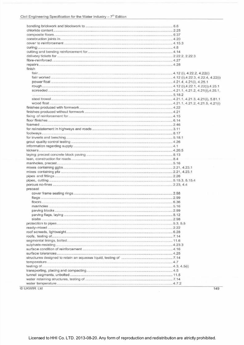
7/21/2019 The Civil Engineering Specification for the Water Industry 7th
http://slidepdf.com/reader/full/the-civil-engineering-specification-for-the-water-industry-7th 155/176Licensed to HHI Co. LTD. 2013-08-20. Any form of reproduction and redistribution are atrictly prohibited.
Civil Engineering Specification for the Water Industry yth Edition
bonding brickwork and blockwork to ..............................................................
..
.
..
.................. 6.6
chloride content ..................................................................................................................... 2.25
composite floors ............................................................ .... ...... .......................... ....................6.37
construct ion joints in ................................
.. .. ....
......... ...... ............................................ ........... 4.20
cover to
reinforcement ........................ ............. .....................................
..
.............................. 4.15.3
curing ...............................
..
...... .................................
..
................................... ....................... 4.8
cutting and bending reinforcement for ..................................................................................4
.1
4
delivery tickets for ................................................................................................................. 2.22.2, 2.22.3
fibre-reinforced ...................................................................................................................... 4.27
repairs ..........
..
.......................................................................................................................4.28
finish
fa ir ...................................................
..
........
..
.....................................................................4.12 i), 4.22.2, 4.22 i)
fa
ir
worked .................................................. ..................................................................... 4.12 i),4.22.3, 4.22.4, 4.22 i)
power float .................... .... ............
..
.... ..... ......
..
.......... ...................................................... 4.21.4, 4.21 i), 4.25.1
rough ...................................... ......
..
................................................................ .................. 4.12 i),4.22.1, 4.22 i),4.25.1
screeded ............ ..............................................
................................................. ...............4.21.1, 4.21.2, 4.21 i),4.25.1,
......................... ................................................................................................................ 5,18.2
steel trowel. .....................................................................................................................4.21 .1, 4.21 .3, 4.21 i), 5.81.1
wood
float ........................................................................................................................ 4.21.1, 4.21.2, 4.21.5, 4.21 i)
finishes produced with formwork ........................................................................................... 4.22
finishes produced without formwork ...................................................................................... 4.21
fixing of reinforcement for .................... ...... ......... .................................................................. 4.15
floor finishes .......................................................................................................................... 6.14
foamed .............................................................................
..
.............................. ..... ................2.46
for re
in
statement in highways and roads .....................................................
.. ..
...................... 3.11
footways ............................................................................................... ................................. 8.17
for inver ts and benching ......................... .......... ...........................................
..
........................ 5.18.1
grout quality control testing ...... ............................................................................. ................4.26
information regarding supply .................................................................................................
4.1
kickers .........
....
...................................................................................................................... 4.20.5
laying precast concrete block paving .................................................................................... 8.13
lean, construction for roads ...................................................................................................8.4
manholes, precast ... ......... ............................... ...................................................................... 5.16
mixes containing ggbs........................................................................................................
..
. 2.21, 4.23.1
mixes containing pta ............................................................................................................ . 2.21 , 4.23.1
pipes and fittings ................................................................. .................................................. 2.26
pipes, cutting ............ .............................................................................................................
5.
15.3, 5.15.4
porous no-fines ............................................................................................. ......... ............... 2.23, 4.4
precast
cover
frame seat
ing
rings
..................................................................................
.......
........
2.98
flags ...........................................................................................................
..
....................2.99
floors ................................................................................................................................ 6.36
manholes ......................................................................................................................... 5.16
paving blocks ....... ......... ....... ......................................... ......... ...................... ....................2.99
paving flags, laying ..............................................
.. ..
... ..................................................... 8.12
slabs ........................................................... ......................
..
... .... ...................................... 2.98
protection to pipes ................................................................................................................. 5.3, 5.5
ready-mixed .............. ............................................................................................................ 2.22
roof screeds, lightweight.. ................................
..
.................................................................... 6.28
roofs, testing of. ............................................................................................. ....................... 7.14
segmental linings, bolted............................. .......................................................................... 11.6
sulphate-resisting ............................................
..
..................................................... ...............4.23.3
surface condition
of
reinforcement ............................ ............................................................ 4.16
surface tolerances .....
..
..............................................................................
..
.......... ................ 4.25
structures designed to retain an aqueous liquid, testing
of
...............
..
...... ........ ...... ............. 7.14
temperature ............................. ..... .... .........................
..
.......................................... .......... ...... 4.7
testing of ............................. ..
..
..............................................................................................4.3, 4.5 i)
transporting, placing and compacting ....................................... ............................................. 4.5
tunnel segments, unbolted .............................................. ......... ............................................. 11 .5
water retaining structures, testing
of
..................................................................................... 7.14
water temperature ................................................................................................................. 4.7.2
©U
KWIR Ltd
149
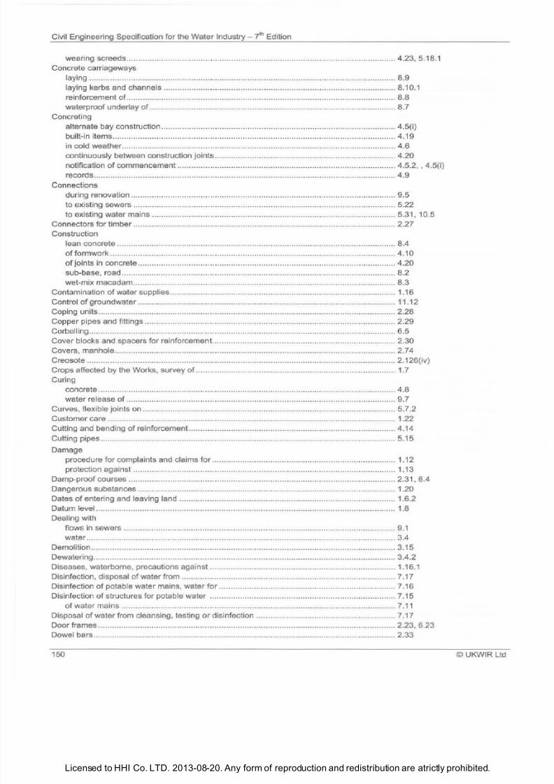
7/21/2019 The Civil Engineering Specification for the Water Industry 7th
http://slidepdf.com/reader/full/the-civil-engineering-specification-for-the-water-industry-7th 156/176Licensed to HHI Co. LTD. 2013-08-20. Any form of reproduction and redistribution are atrictly prohibited.
Civil Engineering Specification for the Water
Industry 7lh
Edition
wearing screeds ... ................................................................................................................ 4.23, 5.18.1
Concrete ca rriageways
laying ... .......................................................................................................... ....................... 8.9
laying kerbs and channels ....................................................................................................
8 1
0 1
reinforcement
of
................................................................................................................... 8.8
waterproof underlay of ......................................................................................................... 8. 7
Concreting
alternate bay construction ..................................................................................................... 4.5 i)
built-in items .......... ..... ........................... ...................... ........ .......... ..... ................................ .. 4.19
in cold weather ...... ............................................................................................................ . 4.6
continuously between construction joints .............................................................................. 4.20
notification of commencement .............................................................................................. 4.5.2, , 4.5{i)
records ................................................................................................................................. 4.9
Connections
during renovation ............. ..................................... ......... ........................... .......... ................ 9.5
to existing sewers ............................... ....................... ....................................................... 5.22
to existing water mains ... ...................................................................................................... 5.31, 10.5
Connectors for t imber ................................................................................................................. 2.27
Construction
lean concrete ........................................................................................................................ 8.4
of
formwork ........................................................................................................................... 4.10
of o
ints in concrete .............. ................................................................................................. 4.20
sub-base, road ............. ......................................................................................................... 8.2
wet-mix macadam................................................................................................................. 8.3
Contamination of water supplies ................................................................................................. 1.16
Control of groundwater ............................................................................................................... 11.12
Coping units ................................................................................................................................ 2.28
Copper pipes and fittings ............................................................................................................ 2.29
Corbelling ................................ ................................
.................................................................. 6.5
Cover blocks and spacers for reinforcement... ........................................................................... 2.30
Covers, manhole ........................................................................................................................ 2.74
Creosote ............................................................ ......................................................................... 2 126 iv)
Crops affected by the Works, survey of ..................................................................................... 1.7
Curing
concrete ......................................... ................................... ............................... ....... ............ 4.8
water release
of
....... ........................................................................................................... 9.7
Curves, flexible joints on ............................................................................................................. 5. 7.2
Customer care ............................................................................................................................ 1.22
Cutting and bending
of
reinforcement ............................................................................ ............. 4.14
Cutting pipes .............................................................................................................................. 5.15
Damage
procedure for complaints and claims
for
............................................................................... 1.12
protection against ................................................................................................................. 1.13
Damp-proof courses ...................................................................................... ............................. 2.31, 6.4
Dangerous substances ............................................................................................................... 1.20
Dates
of
entering and leaving land ............................................................................................. 1.6.2
Datum level ................................................................................................................................. 1 8
Dealing with
flows in sewers ...... ........................... .........................
.........................................................
9 1
water ..................................................................................................................................... 3.4
Demolition ................................................................................................................................... 3.15
Dewatering ................................................................................................................................. 3.4.2
Diseases, waterborne, precautions against ................................................................................ 1.16.1
Disinfection, disposal of water from ............................................................................................ 7.17
Disinfection
of potable water mains, water
for
............................................................................ 7.16
Disinfection of structures for potable water ................................................................................ 7.15
of
water mains ...................................................................................................................... 7.11
Disposal of water from cleansing, testing or disinfection ............................................................ 7.17
Door frames ................................................................................................................................ 2.23, 6.23
Dowel bars ....... .......................................................................................................................... 2.33
150 ©UKWIR Ltd
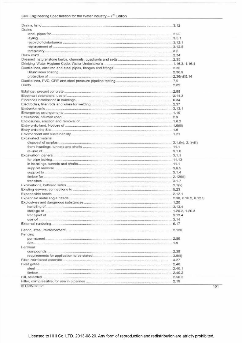
7/21/2019 The Civil Engineering Specification for the Water Industry 7th
http://slidepdf.com/reader/full/the-civil-engineering-specification-for-the-water-industry-7th 157/176Licensed to HHI Co. LTD. 2013-08-20. Any form of reproduction and redistribution are atrictly prohibited.
Civil
Engi
neering Speci
fi
cation for the Water Ind
ustry- i
Edition
Drains, land .....
..
.. ...........................................
..
...
..
.......................... ........................ ..................
..
3.12
Drains
land, pipes for ...... .
..
........................................................
..
.. ............ ......... ............................
..
2.92
layi
ng
.................. ............................. .. ............................
..
........................ ........ ........... .
..
....... 3.5.1
record of disturbance ...... ............
..
................................ .................. ..... ......... ......... ............... 3.12.1
repl
acement of
....
............... .
..
............ .......... .......
..
......... ........................................................ 3.12.5
tem
porar
y ............ .... .
..
..... .........
..
....... ..... .... .. .... .. .
..
......
..
............................
..
......................... . 3.5
Draw
cord
............. ..................
..
......... ......
..
.. .......... .
..
..... ..
.. ..
...............
..
...... .........
..
...................... 2.34
Dressed natural stone kerbs, channels, quadrants and setts ............ ......... ........
..
..................... .. 2.35
Drink ing Water Hygiene Code, Water Undertaker s .......................................................
..
........... 1.16.3, 1.16.4
Ductile i
ro n
cast iron and steel pipes, flanges and fittings .......................................................... 2.36
Bituminous coating ................................................ ..... .
..
....................................................... . 2.36.9
protection of ........ ............................................................... .......... ..... ................
..
.................. 2.36 vi)5.14
Ductile iro
n PVC GRP
and steel pressure pipeline testing .........
..
......................
..
..................... 7.9
Ducts .... ..................
..
..
...................
..
.... ..... ...........
.. ..
..
..
..... .
..
......... .....
..
........................................ 2.89
Edgings, precast concrete .............................................................. ......... ................................ .... 2.98
Electrica detonators, use of ......................................... .......................................................... .... 3.14.3
Electric
al
installations in buildings ..................................
..
....................................................... ..
..
6.34
Electrodes, filler
ro
ds and wires
for
welding .............
..
.... ....
..
..... .......... .... .......... ......................... . 2.37
Embankments .............. ......................... .......... ..... .......
..
.
..
.
....
.... .......
..
........... ........ ................... ... 3.1
3.1
Emergency arrangements ...................................................................................
..
........ .............. 1.19
Emulsions, bitumen road........................... ....... ..... ........ .............................................................. 2.9
Enclosures, erection and removal of .........................
..
.................................. .............................. 1.6.2
Entry onto land, Notices of ..........................
..
.............................................................................. 1.6 iii)
Entry onto the Site ........................................................ ....................... ....................................... 1.6
Environment and sustainability .................................................................................
..
................ 1.21
Excavated material
disposal of surplus ...................... ..... ...... ............................ .. .... .............................................3.1. iv), 3.1 viii)
from headings, tunnels and shafts ........ .. ..... .................. ..
..
............ ....................................... 11.1
re-use
of .......... ...................................... .................................................. ............................. 3.1.6
Excavation, general ........ .......................................................................... ..... ......... ..... ................ 3.1.1
for
pipe
jacking ...................................................................................................................... 11.13
in headings, tunnels and shafts ... .. ........................................................................................ 1
1.1
support removal .............. ............. ........................ ................................................................. 3.6.5
support
to .............................................. ......... .. .... ................................................................. 3.1.4
timber for ......................................
..
..................
..
.. ........ ....................... ..... ........ ..................... 2.126 i)
trenches .... ... ........................................................ ................................................................. 3.1.7
Excavations, battered sides ........ ............................... ............
..
............ ................
..
...... ...............
3.1
v)
Existing sewers, connections to .... .............................................................................................. 5.23
Expandable beads ....................................... ............................................................................. .. 2.12.1
Expanded metal angle beads ............................. ......................................................................... 2.38, 6.10.3, 6.12.5
Expl
osives
and dangerous substances .......................................................................................
1.
20
handling of ................ ... ......................................................................................................... 3.13.4
storage
of
........................................................................................................ ...... ................ 1.20.2, 1.20.3
transport of ........... .....
..
.................
..
......
..
.... ............ .......
..
....................
..
...
.. .. .. ..
...
..
. .. ........
..
.. 3.1 3.4
use
o
................................................................................................ ..... .
..
..... .....
..
........ ..... ..
3.1
4
External rendering ........
..
...................... ................................................ ....................................... 6.17
Fabric, steel, reinforcement ..............
..
.
..
...... .......................... ........................................ ............. 2.120
Fencing
permanent ......................... ..................... .....
..
.......... .... ..... ... ............... ...
..
........ ........ ....
...
..... .. 2.89
Site . . ......................................................................................... ... ...... .................................... 1.9
Fertiliser
compounds ............ ... ..............
..
..................
..
....... ... .... .............. ......... ..... ... .............. ............. 2.39
requirements for
app
lication to be stated .............................................................................. 3.9 ii)
Fibre-re
in f
orced concrete ........ ..................... ......................................................... ..............
..
...... 4.27
Field
gates
.................. ....... ......... ..... ..
..
......................... ........ ........................................... ..... ...... 2.40
steel .............
..
..............................
..
.......
..
........ ..... ... ........ ...................................................... 2.40.1
timber
.............................................................. ........ .......................... ....... .. .... .... .......... ..... .... 2.40.2
Fill, sel
ected ........ ..................................................... ..... ....... ....................................................... 2.50.2
Filler, compressible, for use in pipelines .......................................................... .... .... ..... ......... ..... 2.19
©
UKWIR Ltd
151
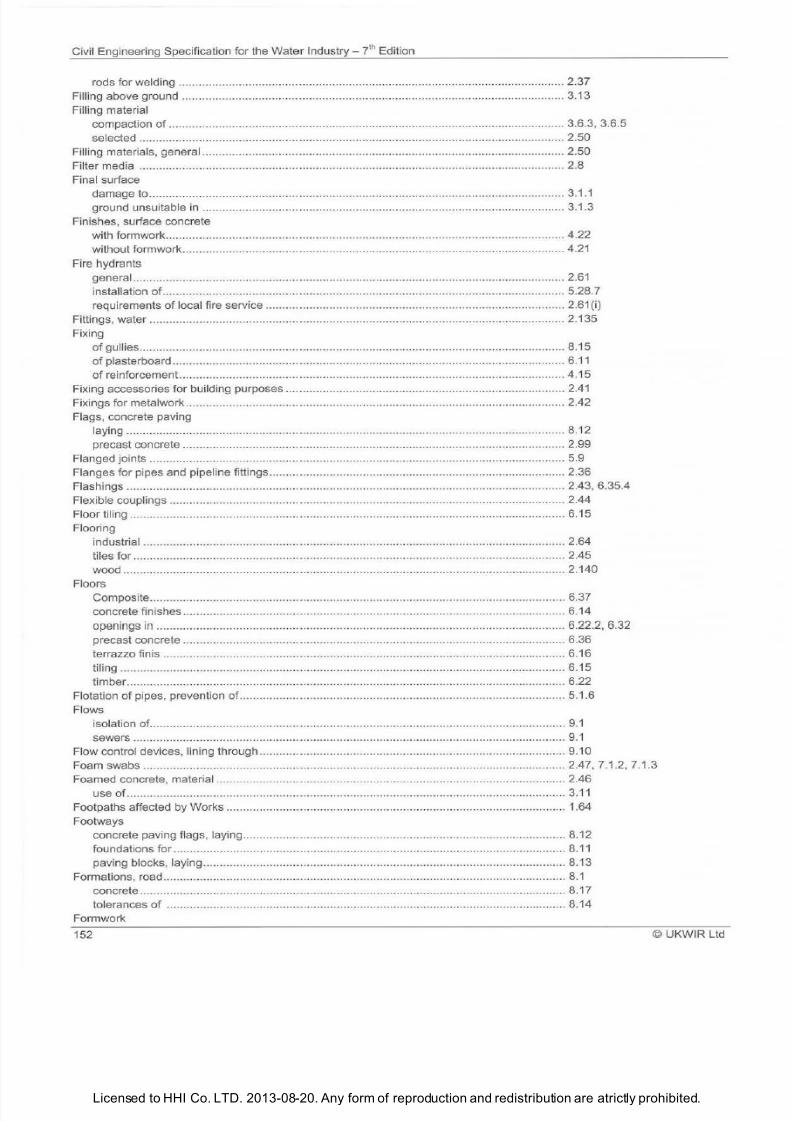
7/21/2019 The Civil Engineering Specification for the Water Industry 7th
http://slidepdf.com/reader/full/the-civil-engineering-specification-for-the-water-industry-7th 158/176Licensed to HHI Co. LTD. 2013-08-20. Any form of reproduction and redistribution are atrictly prohibited.
Civi l Engineering Specification for the Water Industry i Edition
rods for welding ................................................................................................. .............. .... 2.37
Fill ing above ground .......... ......................................................................................................... 3.13
Fill ing material
compaction of ................................................................................ .....................................
3.6.3 3.6.5
selected .................................................... ....................................................................... ..... 2.50
Fi lling materials, general ............................................................................... .............................. 2.50
Fi lter media ........ ............... .......................... ........................................................... ................
2.8
Final surface
damage to .......... . ........................ . ...... ............... ........ ..... ................................................
3.1.1
ground unsuitable in ................................. .......... ........ ...................................... ................
3.1.3
Finishes, surface concrete
with formwork .......................................................................................................................
4.22
without formwork ........................ ...................... ........... ......................................................... 4.21
Fire hydrants
general .... ..... ......................... ..... ................................................................... ...................... 2.61
installation of .... ........ ......... .............. ............ .................. ....................................................... 5.28.7
requirements of local fire service ................................... ..... ............ .................................... 2.61 i)
Fittings, water ...
........................ .......................... ..... ..................... ....................... ................. 2.135
Fixing
of
gullies .......................................................................... ............................................ ..........
8.15
of plasterboard ......................................................................................................................
6.11
of reinforcement ................................................................................. ..... ............................
4.15
Fixing accessories for building purposes .................... ..... ....................... ....................................
2.41
Fixings
for
metalwork ......... ...............
......................... ............................................................. 2.42
Flags, concrete paving
laying ........... ........................................................................................ ......... ......... . ...... ....
8.12
precast concrete .......... ......... .............................. .......................... ..... ..... . ... ................ 2.99
Flanged joints ........ ..... ..... ................. ........... .................................. ..................................... 5.9
Flanges for pipes and pipe
li
ne fittings ............ ....... .................................................................
2.36
Flashings .... ..... ..... ...................................................................................... ......... .....................
2.43 6.35.4
Flexible couplings ..... .............. .............. ......................................................... .......... .............. . 2.44
Floor tiling ........................................................ ........ ..................................... ..............................
6.15
Flooring
industrial .................................. ............ . ......... .......... .....................................................
2.64
tiles for ........................................................................................................................... .......
2.45
wood ......................................................... ....................................... ................................... 2.140
Floors
Composite ..... . .................................................. ........... ................................................... 6.37
concrete finishes .... . ............................................ ..... ........................................................... 6.14
openings in ......................................................... ............................................................. 6 22 2 , 6.32
precast concrete .... ....................................... ........ ............... ............................. ................
6.36
terrazzo finis ..... ........................................ .... ........................................ ................................
6.16
tiling .......................... ........ .................. ...................... .................................. ........................
6.15
timber ..... ......... .... ................................................... ..................... ................................... 6.22
Flotation
of
pipes, prevention of.. ................................................................................................
5.1.6
Flows
isolation of ..... ...... ............ ............ .... ..... .................. .............................. .. ..... ................. 9.1
sewers ........................................................ .......................... .......... ........ .......................... 9 1
Fl
ow
control devices, lining through ............................................................................................ 9.10
Foam swabs .............................................................. ............................................................... 2.47 7.1.2 7.1.3
Foamed concrete, material .......................................................................................... ............. 2.46
useof
..... ........................................... .............................................. ........ . ............ . .... 3 1 1
Footpaths affected by Works ........................................................................................ ..... ....... 1.64
Footways
concrete paving flags, laying ................................ ............................................................ 8.12
foundations for ....................... ................................................ ............................................... 8.11
paving blocks, laying ................. ..................................... .......................................................
8.13
Formations, road .......... ....... .............. ................................................................. .....................
8.1
concrete ... .............. ... ........ ......................................... . ... .......................... ........... ......
8.17
to
lerances of ........................................................................................................................
8.14
Formwork
152
© UKWIR Ltd
7/21/2019 The Civil Engineering Specification for the Water Industry 7th
http://slidepdf.com/reader/full/the-civil-engineering-specification-for-the-water-industry-7th 159/176
7/21/2019 The Civil Engineering Specification for the Water Industry 7th
http://slidepdf.com/reader/full/the-civil-engineering-specification-for-the-water-industry-7th 160/176Licensed to HHI Co. LTD. 2013-08-20. Any form of reproduction and redistribution are atrictly prohibited.
Civil Engineering Specification for the Water Industry
? h
Edition
pipelaying in .......................................................................................................................... 5.5
Headings, tunnels and shafts ................................................................................................... 11.1
Herbicides and pesticides, use of, protection of agricultural land ............................................... 1.14
Highways, affected by the Works, survey
of
............................................................................... 1.7
works affecting ...................................................................................................................... 1.18
Highways, maintainable, reinstatement
of
.................................................................................. 3.7
non-maintainable, reinstatement of ...................................................................................... 3.8
Highways and roads, reinstatement of openings in, using foamed concrete .............................. 2.46, 3.11
Hot rolled asphalt, laying ........................................................ .................................................... 8.6
Hydrants, surface box frames and covers .................................................................................. 2.61
Hygiene, water supply ................................................................................................................ 1.16
Imported topsoil .......................................................................................................................... 2.62
Imported turf ............................................................................................................................... 2.63
Indicator posts, and markers ...................................................................................................... 5.25
Industrial flooring, walkways and stair treads ............................................................................. 2.64
Infectious diseases, notification of .............................................................................................. 1.16.4
Infiltration into non-pressure pipelines and manholes ................................................................. 7.8
In-situ epoxy resin lining ............................................................................................................. 10.3.2
Insurance, office contents ........................................................................................................... 1.2 v)
In-situ concrete manholes and chambers ................................................................................... 5.19
Inspection after grouting ........................... .................................................................................. 9.9
Inspection
after renovation of sewers .................................................................................................... 9.11
after renovation of water mains ............................................................................................ 10.7
of pipelines, CCTV ..................................................................................... ........................... 7. 7
Insurance for accommodation ........................ ............................................................................ 1.2 v)
Installations, electrical ................................................................................................................. 6.34
Interference with
any access
to
property, apparatus or service ....................................................................... 1.11
land interests ........................................................................................................................ 1.10
Inverts and benchings, manhole ................................................................................................. 5.18.3
Isolation
of
flows
sewers ..................................................................................................................................
9 1
Jacking, concrete pipes for ......................................................................................................... 2.26.3
pipe ........................ ............................................................................................................... 11.13
Joinery and carpentry ................................................................................................................. 6.19
timber ................................................................................................................................... 2.65
Joint
filler board ............................................................................................................................. 2.66
seals and lubricants, pipe ..................................................................................................... 2.67
sealing compounds and sealants ............................................................................. ............ 2.67
Jointing, genera
lly ....................................................................................................................... 9.4
of pipes ........................ ................................................................................................... ...... 5. 7
Jointing strip, bituminous, for tunnel and s
haft
segments ........................................................... 2.11
Joints
cement mortar ...................................................................................................................... 5.12
ferrous, protection of ............................................................................................................ 5.14
flanged .................... ..... ......... ...................... .......................................................................... 5.9
flanged, gaskets
for
..................................... ......................................................................... 2.49
ogee ...................................................... .... ........................................................................... 5.10
pointing of ............................................................................................................................. 11.9
protection of ferrous ............................................................. ................................................. 5.14
run lead................................................................................................................................. 5.13
welded, plastics pipes ........................................................................................................... 5.8
welded, steel pipes ................................................................ ........................................... 5.11
Joints and laps, reinforcement .................................................................................................... 4.17
concrete construction ................................................................................................... ....... 4.20
in building construction ......................................................................................................... 6.35
run lead, pipe ........................................................................................................................ 5.13
welded, plastics pipe ............................................................................................ ................. 5.8
154 UKWIR Ltd
7/21/2019 The Civil Engineering Specification for the Water Industry 7th
http://slidepdf.com/reader/full/the-civil-engineering-specification-for-the-water-industry-7th 161/176
7/21/2019 The Civil Engineering Specification for the Water Industry 7th
http://slidepdf.com/reader/full/the-civil-engineering-specification-for-the-water-industry-7th 162/176Licensed to HHI Co. LTD. 2013-08-20. Any form of reproduction and redistribution are atrictly prohibited.
Civil Engineering Specification for the Water In
dustry J h
Edition
approval for colour
of
profiled steel ............................................................................ ........... 6.35 i)
consent for accommodattion ........... .
..
...
.. ..
....
..
.....
..
........................................................... .... 1.2 i)
consent for noticeboards and signboards ................... .... ...................................................... 1.3
i
ii)
Lubricants
for
pipe joints ....... ...................................................................................................... 2.68
Macadam, coated ................................... .. ... ......... ........................................................... ........... 2.16
coated, laying ...... .............................. ..................................... ........ .. .. ..... .............................. 8.5
wet-mix .... ....
..
.................................................................
..
..... .
.. ....
..... .
..
.
....
........................... 2.137
wet-mix construction
..
........ ................
..
. .......................................................... ...................... 8.3
Mains bursting
..
......................................................................................................................... . 5.30.1
Making good surface finishes
of
concrete
..
....... ..................................................... ..... ................ 4.28
Manholes and chambers
covers and frames ................................................................................................................ 2. 74
brick ....... .......................... ......... ............................ ..... .... ......... ....................... ....................... 5.17
inverts and benchings ........................................................................................................... 5.18
pipes and joints adjacent to ..................................................................... ..... ......... ............... 5.19
precast concrete, and soakaways ....... ....................... ..... ......... ............... ..... ........................ 2.101
precast concrete, construction of ......................................................................................... 5.16
precast concrete, segmental, construction of... ..................................................................... 5.17
rendering of.. ....... .............................................................................................. ..... ............... 6.1 i)
setting ....................
..
............................. ...................................... ....... ..... ..... ......................... 5.21
step irons
for
. .... ..................................... .............................................................................. 2.70
to be abandoned .... ..........................................................................
..
..............
..
................... 5.23
watertightness of..... ..... ....... ......... ................................. ..... ........ ..... ................................... .. . 5.20
Marker and indicator posts ...... ................................................................. ........ ...... .............. ...... 2.76.4, 2.76.5, 2.76.6, 5.26
for cables ..... ............. ........................ ......... ......... ............................... ............ ...... ................. 2.76.2
for wastewater pipes and pumping main ................................................ ..... .......... ................ 2.76.3
for water mains .......... ........
..
.....................................
..
.......................................................... 2.76.1 , 5.25
Marker tape and marker post ......................................................................................... ............ 2.76
Marking
of
precast concrete components ....................................................................... ......... .
..
2.98.3
Mastic asphalt ............ .. .. ................................................... ......... ...................... ........................ ... 2.77
Materials in contact with potable water ......................................................................... .............. 2.1
Materials, storage, handling and use
of
.....................
..
.... .... .......................................................
2.1
Mattresses, rockfi ll, and gabions ................................................................................................. 2.47
Mechanical couplings
for
pipelines and fitti
ngs
........................................................................... 2.8
corrosion protection
of ............................ .............................................................................. 2.78.4, 2.78.5
for iron pipes ....................... ...... ............................................................................................ 2.78.1
for polyethylene pipes ......... ................................ ......... .............................. .......... ................. 2.78.2, 2.78.3
Media
for
percolating fi lters ...................... ..................... .......... .......................... .......................... 2.8
Medical aspects of work in compressed air ............... .......... ....................................................... 11 16
Medical testing
of
employees before contact with potable water supplies .................................. 1.16.1
Metal lathing ............................................................. .................. ........ ........ ......... ...... ...... ..... ..... . 2.79
Metal ties for use in cavity walls ...................
..
........
.. ..
................................................................ 2.80
Metalwork, fixings for ..
..... ....................... ... ...... .......................................................... ........... ...... 2.42
Microtunnelling......... ......................................................................................... ........................
..
11.14
Mineral aggregates for flat roofs .................................................................. ............................... 2.81
Mortar .. ....................... ........................................ ....................... ................................................. 2.82
lime for ... .. ....................................................................... ..... ................................................. 2.72
ready for use retarded ........ ................ ....... .......................... ................................................. 2.82.3
Nails...................... ..................................................................................................... .............. .
..
2.83
National Water Hygiene Card ........................................................................ ............................. 1.16.2
Natural stone ........ ......... ..................
..
............................................................
.. ..
..... .................... 2.84
Nightwork in headings, tunnels and shafts ......... ........................................................................ 11.1.1
Non-concrete water reta ining structures, testing of.. ........ .......... ................................................. 7.18
Non-man access chambers .
..
......... ....................................................................
.. ..
.................... 2.85
Non-potable water mains ..... ............................................. .... .
..
..............
..
...........
..
.
......
....
..
........ 2.132 i)
Non-pressure pipelines
air test
for
.
...................................................................................................... ...................... 7.6
infiltration to ........... .... ......... .......... ........................... ............................................................. 7.8
testing ............................ ......... ..... .................................... ........ ....................................... ...... 7.4
water test for ...................................... .. ................................................................................. 7.5
156
©UKWIR Ltd
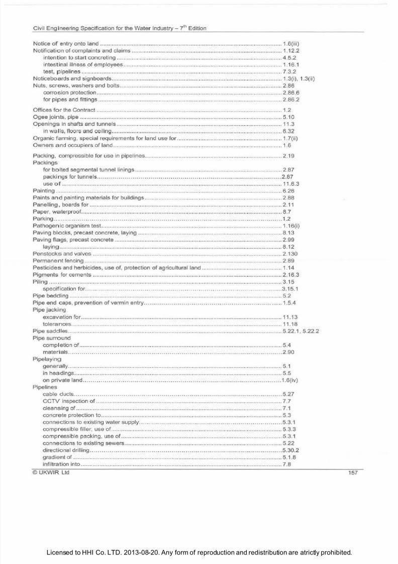
7/21/2019 The Civil Engineering Specification for the Water Industry 7th
http://slidepdf.com/reader/full/the-civil-engineering-specification-for-the-water-industry-7th 163/176Licensed to HHI Co. LTD. 2013-08-20. Any form of reproduction and redistribution are atrictly prohibited.
Civil Eng ineering Specification for the Water
Industry
J h Edition
Notice of entry onto land ............................................................................................................. 1.6 iii)
Notification
of
complaints and claims .......................................................................................... 1.12.2
intention to start concreting .......... ..... .... ...... ........................................ .................................. 4.5.2
intestinal illness of employees ............... .............................................. .................................. 1.16.1
test, p ipe
li
nes .. ... ... ......... ........... ......... .................. ........ ..... ... .. ............. ..... ......... ....................7.3.2
No
ti
ceboards and signboar
ds
............................................ ......................... ..... ................ ........... 1.3 i , 1.3 ii)
Nuts, screws, wash
er
s and bolts ................... .
..
................
..
..... .................................................
..
. 2.86
corrosion protection ...................................... ......................................................................... 2.86.6
for pipes and fittings ........................................................................................ ...................... 2.86.2
Offices for the Contract ............................................................................................................... 1.2
Ogee
join
ts, pipe ......................................................................................................................... 5.10
Openings in shafts and tunnels ................................................................................................... 11.3
in wa l ls, floors and ceil ing ................................................................................... ................... 6.32
Organic farming, special requirements for land use for ... .......................................... .. ......... ...... 1.7 ii)
Owners and occupiers of land ...... ......... .............. ........................................ ..... ........................... 1.6
Packing, compressible for use in pipelines ....................................................... ..........................2. 19
Packings
for bolted segmental tunnel linings ............................................................ ............................2.87
packings for tunnels ............................................................................................2.87
use
of ....................................................................................................................................
11.6.3
Painting ....................................................................................................................................... 6.26
Paints
and
painting materials for buildings ............ ........ .... ... .................................. ..................... 2.88
Panell ing, boards f
or
............................................................ ....................................................... 2.11
Paper, waterproof ................................... ........................................... ................... .... .................. 8.7
Park ing.... ......... ... . ... . ................................... .......................... . .. ... .. ... . .... .... .. . .. .... ....1.2
Pathogen ic organism test.. ................................................ .......................................................... 1 16 i)
Paving blocks, precast concrete, laying ...................................................................................... 8.13
Paving flags, precast concrete .................................................................................................... 2.99
laying ..................................................................................................................................... 8.12
Penstocks and valves ................................................................................................................. 2.130
Permanent fencing ...................................................................................................................... 2.89
Pesticides and herbicides, use of, protection
of
agricultural land ................................................ 1.14
Pigments for cements ...... ......................................................... .................................................. 2.16.3
Piling .. ... . ................... ................................... ......... ........ .... ........ .................................................. 3.15
specifi cation for .............................. .... .. ... ......... .... ..... .... ...... .................. ......... ....3.15.1
Pipe bedding ........... ......................................... ........................................................................... 5.2
Pipe end caps, prevention
of
vermin entry
...............................
.
.....................................
1.5.4
Pipe jacking
excavation for ....................................................................................................................... 11.13
tolerances ............................................................................................................................. 11.18
Pipe saddles ............................................................................................................................... 5.22.1, 5.22.2
Pipe surround
completion
of
.............................................. ....
..
...... ......................................... .....
..
..
..
.......... 5.4
mater ials ................ . .... .................. ..... ...................................................... .........2.90
Pipelaying
ge
nera
ll
y
..
........ ............................................... ......................................................................5. 1
in headings ......................................... .
..
............................................................................... 5.5
on private land.............. ............................................................. .................... .....1.6 iv)
Pipelines
cable ducts ........................................................................................................5.27
CCTV inspection
of
..................................... ..................... ..................................................... 7.7
cleansing
of
...................... ....................................................................................................
7.1
concrete protection to ............................................................................................................ 5.3
connections to existing water supply ........... .
............
. .
.................
. ...........................5.3.1
compressible filler, use of. .................................................................................................... 5.3.3
compressible packing, u
se
of
.
........ .... .................................................................................. 5.3. 1
connec
tions to existing sewers ........ .............................................. ....................................... 5.22
directional drilling.................................................................................................5.30.2
gradient of ............................................................................................................................. 5.1 .8
infiltration into .................................................................................................. ...................... 7.8
©UKWIR
Ltd
157
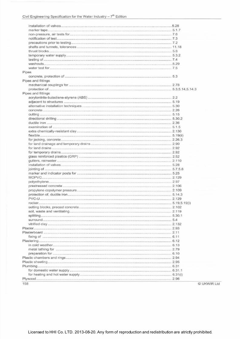
7/21/2019 The Civil Engineering Specification for the Water Industry 7th
http://slidepdf.com/reader/full/the-civil-engineering-specification-for-the-water-industry-7th 164/176Licensed to HHI Co. LTD. 2013-08-20. Any form of reproduction and redistribution are atrictly prohibited.
Civil Engineering Specification for the Water Industry ? h Edition
installation of valves .... •..... ... •.... ....•..... .... ... .•........ . .......... .......................... .........5.28
marker tape ........... . ..... .......... .. ....... .. .... ....... .
...................
....... ................................... 5.1.7
non-pressure , air tests for ................................................................................................... .. 7.6
notification of test ....................................................................................................
...... ....
7.3
precautions prior to testing ................................................................................................... 7.2
shafts and tunnels, tolerances .............................................................................................. 11.18
thrust blocks ..........
........ ...........
..... .... ..... ........ ......... ......................................................... 5.6
temporary water supply .................................................. ...................................................
. 5.3.2
testing of .................................................................................. ............................................. 7.4
washouts ......................
...........
. ............ .. ... .............. .... .
.....................................
5.29
water test for ............................................
....................................................................... 7. 5
Pipes
concrete, protection
of
.......................................................................................................... 5.3
Pipes and fittings
mechanical couplings for ........................ ............. ......... ........
............................................ 2. 78
protection of ................................................... ...................................................................... 5.3,5.14,5.14.3
Pipes and fittings
acrylonitrile-butadiene-styrene ABS) ................................................................................... 2.2
adjacent to structures ........................................................................................................... 5.19
alternative installation techniques ....... .................................................................................. 5.30
concrete .....................
......................................................................................................... 2.26
cutting ................................................................................................................................... 5.15
directional drilling .................................................................................................................. 5.30.2
ductile iron ............................................................................................................................ 2.36
examination
of
...................................................................................................................... 5.1.5
extra chemically-resistant clay .............................................................................................. 2.130
flexible ................................................. .... .... .......................................................................... 5.19 ii)
for jacking, concrete ............................................................... ........ .......... .... .................... ..... 2.26.3
for land drainage and temporary drains ................................................................................ 2.90
for land drains .............................................. ............................. ............................................ 2.92
for temporary drains ................................................................................ .............................. 2.92
glass reinforced plastics GRP) ............................................................................................ 2.52
gutters, rainwater ................................................................................................................ 2.110
installation
of
valves ........................................................................................................... ... 5.28
jointing
of
.................... .................................
....................................................................... 5.7,5.8
marker and indicator posts for ..................................................... ....................................... 5.25
MOPVC ............................................................................ .......................... .................. ........ 2.129
polyethylene ......................................................................................................................... 2.97
prestressed concrete ............................................................................................................ 2.106
propylene copolymer pressure .............................................................................................. 2.109
protection of, ductile iron ....................................................................................................... 5.14.3
PVC-U...................................................................................................... ............................. 2.129
rocker .... ......... ......... ........................................ .................. .... ............................................... 5.19,5.19 i}
setting blocks, precast concrete ...........................................................................................
2 1
02
soil, waste and ventilating ..................................................................................................... 2.119
splitting ......................
......................... ................................................................................ 5.30.1
surround ............................................................................................................................... 5.4
vitrified clay ....................................................................................................................... .... 2.132
Plaster
................................................................................................................................
..... 2.93
Plasterboard ............................ ........................... ........................................................................ 2.11
fixing of ....... ................................................. ........................................... ............................. 6.11
Plastering.................................................................................................................................... 6.12
in cold weather ..................................................................................................................... 6.13
metal lathing for ................................................................................................................... 2.79
preparation for ......................................................................................................................
6 1 0
Plastic chambers and rings ......................................................................................................... 2.94
Plastic sheeting .............................................................................................
.......................... . 2.95
Plumbing ................................................................................................... .................................. 6.31
for domestic water supply ...................................................................................................
6.31.1
for heating and
hot
water supply ...................................................... ..................................... 6.31 i)
Plywood ...................................................................................................................................... 2.96
158 ©UKWIR l td
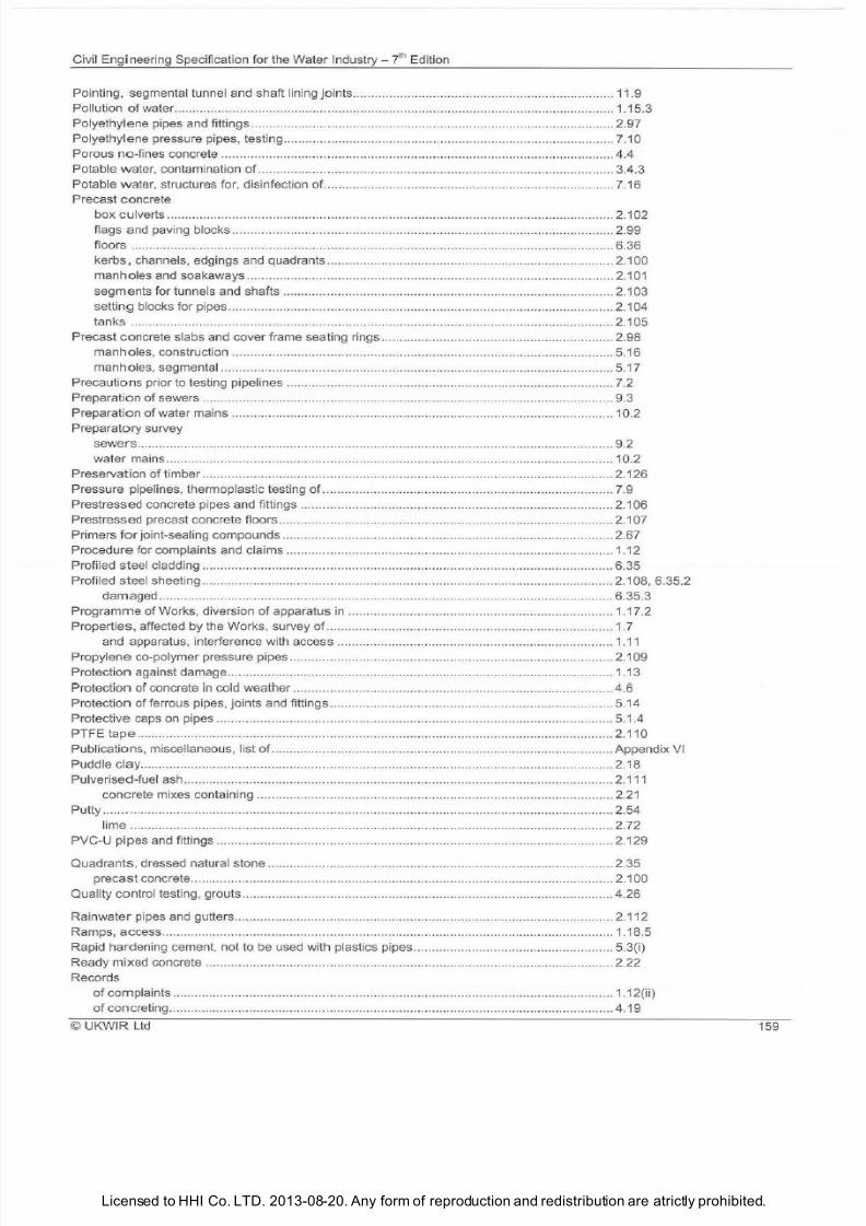
7/21/2019 The Civil Engineering Specification for the Water Industry 7th
http://slidepdf.com/reader/full/the-civil-engineering-specification-for-the-water-industry-7th 165/176Licensed to HHI Co. LTD. 2013-08-20. Any form of reproduction and redistribution are atrictly prohibited.
Civil Engineering Specification for the Water Industry -
i
Edition
Poin
ti
ng, segmental tunnel and shaft lining jo ints..................................... ....... ..... .......... ........... .. 11.9
Pollution
of
water ..................................................................................... ..... ..... ..... ..... ... ..... .. .... . 1.15.3
Polye
th
ylene pipes and fittings ............. ..... ..................................................................................2.97
Polyethylene pressure pipes, testing......... ..................................................... ..... ........................ 7.10
Porous no-fines concrete ........................... .. ............................................................................... 4.4
Potable water, contam ination of ................ ..................................................................... ............ 3.4.3
Potable
water
, structures for, disinfecti
on
of.. ..................
..
... .......
.. ..
..
...
..
.................................... 7.16
Precast concrete
box culverts .... .................................................................. ............. ... .............. ...... ................. 2.102
flags and paving blocks ....... ... ........................................... .............. ......................... ............. 2.99
floors ........ ............................................................................................................................. 6.36
kerbs, channels, ed gings and quadran ts ....................... .. ............................... ....................... 2.100
manholes and soakaways ...... .................................................................... .......... ..... ............ 2.101
segments for tunnels and shafts ............ .......... .................................................................... . 2.103
setting blocks for pipes ..... .............. ....................................................................................... 2.104
tanks
...
............ ................. .......................................... .. ..... ................ ......... .. ..................... .... 2. 105
Precast concrete slabs and cover frame seating rings .......... ....... .................. ........ ..................... 2.98
manholes, construction .... .............. .......................................................................................5. 16
ma
nho
l
es,
segmental .... .................. ................... ........ ... .. ....... .... ........ ... .. ..... .. ... .......... .......... 5
.1
7
Precautions prior to testing pipelines ...................................................................................
.. .. ..
. 7.2
Preparation of sewers .............. ...................................................................................................9.3
Preparation of water mains ................................. .......... ..... ....... ............ ...................................... 10.2
Preparatory survey
sewers ................... ...... ... ................ ............................ ........ ....... ..... .......... ........ ........ .. ...... .. .. 9.2
wat
er
mains ..................................................................................... ................................... ... 10.2
Preservation of timber ................................................................................................................. 2.126
Pressure pipelines, thermoplastic testing of. ..................... .. ...... .. ................................................ 7.9
Prestressed concrete pipes and fittings .................................. ...... ......... ...... .. ....... ...................... 2.106
Prestressed precast concrete floors .......................................................... ................ ..................2.107
Primers
for
joint-sea
li
ng compounds ... .... .................................................................................... 2.67
Procedure for complaints and claims .......................................................................................... 1.12
Profiled steel cladding ............................. ..... .........................
..
.
..
..............
.. ..
... .
.. ..
..... .
.. ..
...... ....... 6.35
Profiled steel sheeting ............................. ..... ......................................... .......... .......... .... ........ ...... 2.108, 6.35.2
damaged ................................... ........... ........ .... ..... ..... ........... ........ ..... .... ...
..
..... ...... .... ......... 6.35.3
Programme
of
Works, diversion
of
apparatus in ......................................................................... 1.17 2
Properties, affected by the orks, survey of ...................... .. ...... .. .................................... .... ....... 1.7
and apparatus, interference with access ....... ...... ............................................................... 1.
11
Propylene co-polymer pressure pipes ...... .... .. ........... .... ..... .. ............................................ ........... 2.109
Protec tion against damage ......... ................................ .. ....... ... ... ..........................
...
.................... 1.13
Protection of concrete in cold weather ........................................................................................ 4 6
Protection of ferrous pipes, joints and fittings.............................................................................. 5.14
Prot
ective
caps
on
pipes ................................................ ........................................... ............ ...... 5.1.4
PTF
tape .................. .... ...... ....... ....... ........................ .... ................ ....
..
................................. ...... 2.110
Pub
li
cations , miscellaneous, list
of
.................................... ..... .. ..................... ................ ..... ........ Appendix VI
Puddle
clay
........ ..... ... .... ..................... .. ......................... ..... ... ................................... ......... ......... 2.18
Pulverised-fuel ash .... ... ..................... ............................. ... .. .. ... ........................... ..... ... .. ........ .. ...
2.1
11
concrete mixes containing ............................ ..................................................................... .2.21
Putty ....... . ...................... ..................... .......... ......... ......... ..... ....... ............. ................. ...... ............. 2.54
lime .. ... .. .... ......... .... .. ... ........ ................................... .................... ........ .... ...... ....................... 2.72
PVC-U pipes and fittings .............. ... ..... ..... ............ ..... ......... .... ... ................................ ........ ..... .. .. 2.129
Quadrants, dressed natural stone ...........................................
..
..... .. .......................... .... ... ...... .... 2.35
precast concrete....................................................... .
..
.. .
..
.
..
......... .. ....................................... 2.100
Quality control testing, grouts .................. ..... .... ...........................................................................4.26
Rainwater pipes and gutters . .. .... ... ...... ..... ....... .. ....... ...... ........ ........ ........ .................................... 2.112
Ramps, access ....................... .............................. ..................... ............................... .................. 1.18.5
Rapid hardening cement, not to be used with plastics pipes .................................
..
......... .
.. ..
...... 5.3 i)
Ready mixed concrete ... .............................. .............................. ........ ........ ........ .. .... ................... 2.22
Records
of complaints ....................................................................
....
.................. ........ ................... .... 1.12 ii)
of concreting ............. ..
..
.
..
......... ...... ...................................
..
................... ...........
..
.................. 4.19
© UKWIR Ltd
159
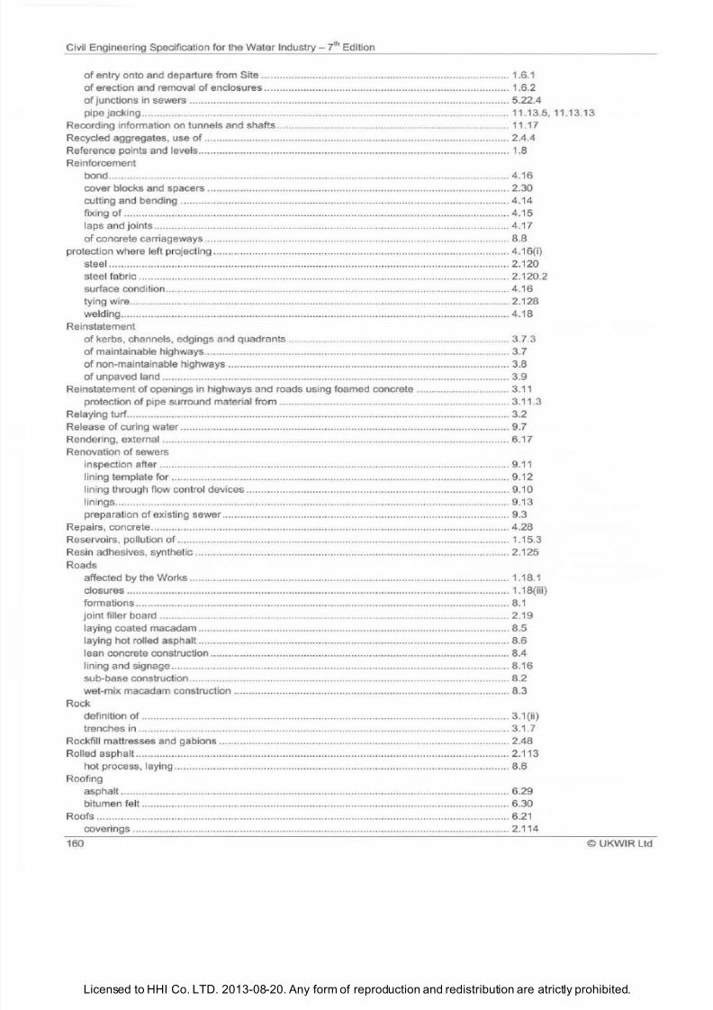
7/21/2019 The Civil Engineering Specification for the Water Industry 7th
http://slidepdf.com/reader/full/the-civil-engineering-specification-for-the-water-industry-7th 166/176Licensed to HHI Co. LTD. 2013-08-20. Any form of reproduction and redistribution are atrictly prohibited.
Civil Engineering Specification for the Water Industry
J h
Edition
of entry onto and departure from Site ... ...................... ....... ................................................. 1.6.1
of erection and removal of enclosures ................... ............................................................. 1.6.2
of junctions in sewers .................................................... ....................................................... 5.22.4
pipe jacking ............................................................................................................. .............. 11.13.5, 11.13.13
Recording information on tunnels and shafts ............................................................................. 11.17
Recycled aggregates, use
of
...................................................................................................... 2.4.4
Reference points and levels ....................................................................................................... 1.8
Reinforcement
bond...................................................................................................................................... 4.16
cover blocks and spacers ..................................................................................................... 2.30
cutting and bending .............................................................................. .......... ...................... 4.14
fi xing of ...................................................................................................... ........................... 4.15
laps and joints ........................................... ............................................................................ 4.17
of concrete carriageways ...................................................................................................... 8.8
protection where left projecting ............................... ........ .......................................................... 4.16 i)
steel ............ .......................................................... ........ ............................................ .... ........ 2.120
steel fabric ............................................................................................................................ 2.120.2
surface condition ................................................................................................................... 4.16
tying wire ....................................................................... ............................... ........................ 2.128
welding ......................................................................................................... ........................ 4.18
Reinstatement
of kerbs, channels, edgings and quadrants .......................................................................... 3.7.3
of maintainable highways ..................................................................................................... 3.7
of non-maintainable highways .............................................................................................. 3.8
of unpaved land .................................................................................................................... 3.9
Reinstatementof openings in highways and roads using foamed concrete ............................... 3.11
protection of pipe surround material from ............................................................................. 3.11.3
Relaying turf ............................................................................................................................... 3.2
Release of curing water .............................................................................................................. 9.7
Rendering, external .................................................................... ............................. ................... 6.17
Renovation
of
sewers
inspection after ..................................................................................................................... 9.11
lining template for ...... ........................................................................................................... 9.12
lining through flow control devices ...
........................................................ ........................... 9.10
linings ......... ......... ......................................... ........ . ......................................... ..... . ......... . 9.13
preparation of existing sewer ................................................................................................ 9.3
Repairs, concrete .............................................. ....................... .................................................. 4.28
Reservoirs, po
ll
ution of ............................................................................................................... 1.15.3
Resin adhesives, syn
th
etic ......................................................................................................... 2.125
Roads
affected by the Works ........................................................................................................... 1.18.1
closures ................................................................................................................................ 1.18 iii)
formations ............................................................................................................................. 8 1
joint filler board ..................................................................................................................... 2.19
laying coated macadam ........................................................................................................ 8.5
laying
hot
rolled asphalt ........................................................................................................ 8.6
lean concrete construction ................... ................................................................................. 8.4
lining and signage................................................................................................................. 8.16
sub-base construction ................................................................................. .......................... 8.2
wet-mix macadam construction ............................................................................................ 8.3
Rock
definition of ........................................................................................................................... 3 1 ii)
trenches in ............................................................................................................................ 3.1. 7
Rockfill mattresses and gabions ................................................................................................. 2.48
Rolled aspha lt .............................................
....................................................... ........... ............
2 1
13
hot
process, laying ......... ..................... ........... ..................................................................... 8.6
Roofing
asphalt ......... ...................................................................................................................... . 6.29
bitumen felt ........................................................ .................................................................
6.30
Roofs .......................................................................................................... ..............................
6.21
coverings .............................................................................................................................. 2.114
160 UK
WIR Ltd
7/21/2019 The Civil Engineering Specification for the Water Industry 7th
http://slidepdf.com/reader/full/the-civil-engineering-specification-for-the-water-industry-7th 167/176Licensed to HHI Co. LTD. 2013-08-20. Any form of reproduction and redistribution are atrictly prohibited.
Civil Engineering Specification for the Water Industry J h Edition
flat, mineral aggregates for ................................................................................................... 2.81
lightweight concrete screeds ................................................................................................. 6.28
slat ing and tiling ....................................................................................................................6.27
testing of, for watertightness .................................................................................... ............. 7.13
Run lead joints ............................................................................................................................ 5.13
Ryegrass
allowable content in imported turf ......................................................................................... 2.56, 2.63
in
grass seed ......................................................................................................................... 2.56
Saddles, p ipe ..............................................................................................................................5.22.1, 5.22.2
Safety chains ..............................................................................................................................2.115
Sample taps ................................................................................................................................ 2.116
Sampling and disinfection of water mains ................................................................................... 7.12
Sampling of concrete .................................................................................................................. 4.3 i)
Sands, building ............. ........................................................................ ...................................... 2.117
Screeds, l ightweight concrete to roofs ........................................................................................ 6.28
Screws, washers, nuts and bolts.................................................................................................2.86
Sealants, joint. ......................................................
.................................................................... 2.67
Secondary linings to segments ................................................................................................... 11.10
Seed,
grass
................................................................................................................................. 2.56
Segmental linings, bolted concrete ............................................................................................. 11.6
Segmental shaft and tunnel linings ............................................................................................. 11.4
Segments
grouting
of
............................................................................................................................ 11.7
secondary linings to ................................................................................................. ............. 11.10
Segments for tunnels and shafts
design of ...............................................................................................................................
2 1
03
precast concrete ....................................... .... ...................................................................2.103
Service, bringing renovated water mains into ............................................................................. 10.8
Services, apparatus and properties, interference with access
to
................................................ 1.11
Setting blocks for pipes, precast concrete .................................................................... ............... 2.104
Setts, dressed natural stone ....................................................................................................... 2.35
Sewers
and manholes, to be abandoned ......................................
................................................... 5.23
annulus grouting of .................................................................................................. ............. 9.8
chambers ................. .................................................... ..... ....
.............................................. 9.6
cured-in-place linings for .......................................................................................................9.17
existing, connections to ......................................................................................................... 5.22
flows in renovation work ......................................................................................
................ 9 1
inspection after grouting............................. ........................................................................... 9.9
inspection after renovation .................................................................................................... 9.11
jointing, generally .... ..................................................................................... ....................... 9.4
junctions and laterals ...................................................... ...................................................... 5.24
linings .................................................................................................................................... 2.118, 9.13
lining template for .................................................................................................................. 9.12
lining through flow control devices ........................................................................
.............. 9.10
patch repairs ... ......... ...................................... ....................................................................... 9.19
preformed
GR
P and GRC units for renovation ...................................................................... 9.16
preformed linings, tolerances for ........................................................................................... 9.14
preparation
of
.............................................................................. ......................................... 9.2
preparatory survey for renovation ......................................................................................... 9.2
reconnection
of
............................................................................ ......................................... 9.5
rendering repairs ................................................................................................................... 9.18
renovation, inspection after grouting ..................................................................................... 9.9
styrene fumes ........................................................................... .................... .......................9.20
Shafts ...................................................................... ................................................. ............... 11.1,11.2
access and egress ................................................................................................................ 11.2.1
and tunnels, grouting
of
segments ........................................................................................ 11.7
and tunnels, recording information ........................................................................................ 11 .17
and tunnels, tolerances for .................................................................................................... 11.18
and tunnels, ventilation of ................................................................................................... 11.15
©UKWIR
l td
161
7/21/2019 The Civil Engineering Specification for the Water Industry 7th
http://slidepdf.com/reader/full/the-civil-engineering-specification-for-the-water-industry-7th 168/176Licensed to HHI Co. LTD. 2013-08-20. Any form of reproduction and redistribution are atrictly prohibited.
Civil Engineering Specification for the Water Industry 7lh Edition
caulking of segment joints .................... . ............................................................................. 11.8
construction, tolerances ............................................................................ ........................ 11.18
grouting of segments ............................................................................................................ 11.7
headings and tunnels ............................................................................................................ 11.1
headings and tunnels, excavation for ..... ......... ..................................... . ......................... 11.1 1
linings, bolted co ncrete segmental, er
ec
tion of.. ............................................. .................... 11.6
openings in .
..................................................................................................................... 11.3
pointing of oints .................................................................................................................... 11.9
precast concrete segments
for
............................................................................................. 2.103
segmental linings, erection
of
............................................................................................... 11.4
segments ..................................................................................................... ........................ 11.2.2, 11.2.3, 11.2.4
signalling systems and telephones in ................................................................................... 11.1.5
ventilation of ......................................................................................................................... 11.15
watertigh
tn
ess of ................................................... ...............................................................
11 11
work in compressed air ..................................................................................... .................... 11.16
Sheet p iles, steel ..... .......................................................................... ..... ........ ...................... 2.121
Sheeting, plas
ti
c ........................................... ..... ......................................................................... 2.95
Shrubs and trees ........................................................................................................................ 2.127
Shuttering (see formwork )
Signalling and signs, road ..................................................................................
.... ................... 1.18(i), 8.16
Site
access to, planning permission for ....................................................................................... 1.6(ii)
clearance
of
.......................................................................................................................... 3 1 (iv)
entry onto ... ...................................................................................................................... 1.6
fencing and gates ................................................................ .......................... ....................... 1.9
materials on .......... ................................... ......... .......... ................................... ....................... 1.5
mud from ............... ................................... ............................................................................. 1.18.6
tidiness ................................................................................................................................. 1.5
Slating and tiling ............................... .......................................................................................... 6.27
Sleeving and sheeting, plastic .................................................................................................... 2.95
Sloping formwork .............................................................................................. ........................ 4.13
Slump test, concrete ............................................................................................. ...................... 4.3.1
Soakaways, precast concrete ........................................................................ ........................... 2.101
Soil, stacking of . ........................................................................................ ......................... 3.3(i)
Soil, waste and ventilating pipes ............................................................................. .................... 2.119
Spacers for reinforcement.. ............................... .................... .......................... . ......................... 2.30
Specification, incorporation into contracts .................................................................................. Appendix 1
Stainless steel
handrails ............. .................................................................................................................. 2.60
ladders .............................................................................................................. .................... 2.70.3
nuts, screws, washers and bolts ........................................................................................... 2.86.4
proprietary fixings ................................................................................................................. 2.42.2
safety chains ......................................................................................................................... 2.115.2
Stair treads, industrial ..................................... .............................................. .......................... 2.64
Starting work on land, notification by Con
tr
actor ..................................................
.................. 1
6 1
Sta
tu
tory Undertakers, consul tation on apparatus ............................... . ..... ......................... 1.17
Steel, structural ...... ......................................................................................... ............................ 2.123
minor members ..................................................................................................................... 6.20
Steel reinforcement. ................................................................................................................... 2.120
Steel sheet piles ............................................................................................... ........................ 2.121
Steelwork, structural ................................................................................................................... 6.20
fastenings, protection ............................................................................................................ 6.20.7
Step irons in manholes ............................................................................................................... 2.75
Stiles .......................... ................................................................................................................. 2.122
Stone
cast .... ..... ............ ................................ . ............................................................................... 2.14
natural ......... ........ ..................................................................................... ............................. 2.84
Storage of materials ................................................................................................................... 1.5, 2 1
Striking of formwork .................................................................................................................... 4.12
Structural steel ............................................................................................................................ 2.123
Structural steelwork .................................................................................................................... 6.20
162
©UKWIR Ltd
7/21/2019 The Civil Engineering Specification for the Water Industry 7th
http://slidepdf.com/reader/full/the-civil-engineering-specification-for-the-water-industry-7th 169/176Licensed to HHI Co. LTD. 2013-08-20. Any form of reproduction and redistribution are atrictly prohibited.
Civil Engineering Specification for the Water Industry - 7th Edition
Structures
cleansing of
.
..........
..
............
..
.............. ..... .... ..... .
..
..... ..... ..... ........ ...... .................................. 7.12
concrete roofs, water retaining, testing of.. ..............................................
..
........................... 7.13
concrete, water retaining, testing of .. .. .................................................................................. 7.14
for potable water, disinfection of... .......................................... .............................. .... ............. 7.15
galvanising of ......... ..................... ........... .............
..
... ......... .......
.. ..
.......... ......... .
.. ..
...
..
.... ........ 6.20.3, 6.20 1iii)
painting
.
............. .................
..
....... .....
..
..................... .
..
...... ........................
..
..........................6.26.1
testing of welds ........................................................................................ .
..
.... .
.. ..
.................6.20 v)
Sub-base construction
materi
al, granular ... .. .. ............. ............................ ..... ........ .. ........ .... .. .. ...... ....... ..... ... ..............2.55
road .... ..... ...................................................................... .... .......
..
..... .
..
...... .... .
..
..... ....
..
...........8.2
supply of information, concreting .........................................................................................
..
4 .1
Support in tunnels shafts and headings .............................................. ........................................ 11 .1.4
to apparatus affected ............. ...................................................... .
...
........ .............................
1.13.2
Surface boxes and guards .............................................................................. ............................ 2.124
Surface finishes, without formwork ............................................................. ........ ........................
4.21
with formwork ....... ................................................................
..
...... ......... .....
..
.............. ..... ...... 4.22
Surround materials, pipe ..... ......... ....................................................
..
......................................... 2.90
Survey of highways, properties and lands ..................................
..
................... ..... .
..
...
..
............... 1.7
preparatory .
.. ..
................................................................................
..
...........
..
..
..
..... .......... ..... 9.2
survey record photographs, format
of
...........................................................
..
...................... 1.7 iii)
Swabbing of potable water mains, water for ............................................................................... 7.16
Swabbing of pipelines ............................. ..........................
..
..................... ........ ........................... 7.1
Swabbing of water mains ............................................................................................................7.11
Swabs, foam ............ ................................................................................... ................................ 2.47, 7.12, 7.1.3
Synthetic resin adhesives .................... ................. ..........
..
.............. .................. ........................
..
2.125
Tape
marker ..............................................
..
..........................
.. ..
.....
..
...........................
..
................2.76
PTFE ................ ........................
..
................................................................. ..........................2 .1 10
Te lephones
in headings and tunnels ........................................................................................................ 11.1 .5
office ........................................................
..
..... ........ ..... ..... ..... ..
..
......
..
......... .
.. .. ..
....... ..........
..
1.2.3
Temperature
brick la ying and blocklaying in cold weather ..............................................
.. ....
...................... 6.9
concrete ........ ............................................................... ................
..
..........
..
........................... 4.7
concrete surface ........................
..
.......................... ......... ......... ........ ............
..
.....
..
..
..
.... .......
..
4.7
concreting in cold weather ..... ..................
..
................
..
........... ........ ................
..
....................4.6
Temporary
drains .................
..
.... .... .....
..
......
..
........... .................. ............... .
..
......................
..
................
..
. 3.5
fencing and gates Site) ..............
..
.......... .............................................................................. 1.9
water supply mains .................. .............................................. .... ...........................................5.32
Terrazzo floor finishes ..................... ..... ..........
..
...
..
.... .................... ....... ..
..
.................................
..
6.16
Test
air,
for
non-pressure pipelines .............. ................................................................................. 7 4 i
,
7.6
TV for pipelines .... .........
..
....... ......... ............................................................ .... ................. 7.4 i , 7.7
concrete cubes ....... ......................................
.. ..
............................... .
..
......... ..... .
..
................
..
4.2 ii)
notification, of pipelines ......... .... ..... ....................................................................................... 7.3
visual for non-pressure pipelines ......... ............................................... ........ .. .. .. ....... ............. 7.4 i)
water, for non-pressure pipelines .................................
..
..... ......... .................... ..................... 7.5
Testing
disposal
of
water from .........................................................................................................
..
7.17
identity of concrete.................
..
................ ........ ............... ....................................... ............... 4.3
initial of concrete ...... ..... ........................................... .. ... .... ...... ........ ......................................4.2
of
concrete water retaining structures ........................
..
......................................................... 7.14
of
grout strength .................................................... ......... .......
..
..... .
..
...................................... 4.26
of
infiltration in non-pressure pipelines and manholes ....
..
.................................... ................ 7.8
of
non-concrete water retaining structures ............................................................................ 7.18
of
non -pressure pipelines .................... ..........
.. .. ..
.......
..
..
..
...................................................
..
7.4
of
potable water mains, water for .............
..
....
..
..................................................................... 7. 18
of service reservoir roofs ........................ .............................................................................
..
7.14
UKWIR Ltd
163
7/21/2019 The Civil Engineering Specification for the Water Industry 7th
http://slidepdf.com/reader/full/the-civil-engineering-specification-for-the-water-industry-7th 170/176Licensed to HHI Co. LTD. 2013-08-20. Any form of reproduction and redistribution are atrictly prohibited.
Civil Engineering Specification for the Water Indust y i Edition
of thermoplastics pressure pipelines ..................................................................................... 7.10
method programme and notification .... ................................................................................. 7.3
pipelines, precautions prior to ............................................................................................... 7.2
pressure pipelines ................................................................................................................ 7.9
water for ............................................................................................................................... 7.16
Thermoplastics pressure pipelines, testing of ............................................................................ 7.10
Thoroughfares affected by Works ............................................................................................ ... 1.6
Thrust blocks, pipeline, casting ....................
............................................................................. 5.6
Thrust ring, pipe jacking, use
of
................................................................................................. 11.13
Tidiness of Site ........................................................................................................................... 1.5
Tie bolts, formwork ............................................................ ......................................................... 4.24
Ties, metal, for use in cavity walls .............................................................................................. 2.80
Ti les
for flooring ......... ......... ........................................................................................................... 2.45
for walls .... .................. ...................... ..... ........... ...... .......................................................... 2.133
Tiling, walls ...................... ........................................................................................................... 6.18
Ti ling and slating
floor ................................................................................................................................... . 6.15
roof .................................................... ...................................................... ........................... 6.27
Timber ........................................................................................................................................ 2.126
before cutting ........................................................................................................................ 6.19.1
connectors for ....................................................................................................................... 2.27
floors ..................................................................................................................................... 6.22
for excavations ..................................................................................................................... 2.126 i)
joinery ................................................................................................................................... 2.65
preservation of
timber .....................................
.................................................................... 2.126
Tolerances
for building works .............................. .................................................................................. 6.33
for concrete surfaces ........................... ............................................................................... 4.25
for finished carriageway surfaces ......................................................................................... 8.14
for pipelines, shafts and tunnels ........................................................................................... 5.26, 11.18
Topsoil
for re-use ........................................... ................................................................................... 3.3
imported .................................................. .............................................................................. 2.62
replacing ................... ..... ..................................................................................................... 3.3.4, 3.9.1
stockpiling ................ ...... ................................................................................................. 3.3.2, 3.3.4
stripping ................................................................................................................................ 3.3.4
Traffic, requirements ................................................................................................................... 1.18
Training ............................................ ......................................................................................... 1.24
Transporting, placing and compacting concrete ......................................................................... 4.5
Trees and shrubs ........................................................................ ................................................ 2.127
planting and maintenance
of
................................................................................................ 3.10
Trenches
backfilling in .......................................................................................................................... 3.6
depth
of
for water pipes ........................................................................................................ 3.1.8
excavation for ....................................................................................................................... 3.1. 7
width of ................................................................................................................................. 3.1.7
Tunnels and shafts
bolted segmental linings, packing for ..................................................................... ............... 2.87
caulking of segment joints .................................................................................................... 11.8
construction tolerances ......................................................................................................... 11.18
groundwater removal ............................................................................................................ 11.12
grouting of segments ............................................................................................................ 11.7
headings and shafts, ..................................................................... ........................................ 11 1
headings and shafts, excavation of.... ................................................................................. 11.1.3
lining, recording of information regarding .............................................................................. 11.17
linings, bolted concrete segmental, erection o
f
........................................................ .......... 11.6
openings in .......................... ........ ......................................................................................... 11.3
pointing
of
oints ................... ........ ......................................................................................... 11.9
precast concrete segments for ............................................................................................. 2.103
recording
of
information ........................................................................................................ 11.17
164
© UKWIR Ltd
7/21/2019 The Civil Engineering Specification for the Water Industry 7th
http://slidepdf.com/reader/full/the-civil-engineering-specification-for-the-water-industry-7th 171/176Licensed to HHI Co. LTD. 2013-08-20. Any form of reproduction and redistribution are atrictly prohibited.
Civil Engineering Specification for the Water
Industry i
Edition
segmental linings erection of ........................................................................... . ................. 11.4
tolerances for .................................................................................................... .................. 11.18
unbolted concrete segments erection of ...... ...................................................................... 11.5
venti lation of ......................................................................................................................... 11.15
watertightness
of
................................... .....................................................
....... ........... 11
1
1
work in compressed air ......................................................................................................... 11.16
Turf
for relaying ............................................................................................................................3.2
imported ................................................................................................................................2.63
laying ..................................................................................................................................... 3.9.4
Tying
wire
.................................................................................................................................... 2.128
Unbolted concrete tunnel segments............................................................................................ 11.5
Underlay waterproof for concrete carriageways ........................................................................ 8 7
Underpin ning brickwork ........ .................................................................................
.... .............
6 7
Unpaved land reinstatement of ........................... ............................................................. .... 3.9
Unplasticised PVC pipes and fittings...................... ................................................................... 2.129
Use of herbicides and pesticides protection
of
agricultural land ................................................. 1.14
Valves ......................................................................................................................................... 2.130
instal lation
of
..........................................
......
................................................................... 5.28
lining through ................................................. .. .................................................................. 10.6
Ventilating soil and waste pipes ................................................................................................. 2.119
Ventilat
ion of tunnels and shafts ................................................................................................. 11.15
Vitreous enamel tanks................................................................................................................. 2.131
Vitrified c lay pipes and pipeline fittings ....................................................................................... 2.132
Wal kways industrial .... ....... . ...................................................................................................... 2.64
Wall
tiles........................................................................................................................................ 2.133
tiling....................................................................................................................................... 6.18
Walls cavity
metal ties for .........................................................................................................................280
openings in .......................................................................... .................................................. 6.32
Washers nuts screws and bolts ........................................................................ ...................... 2.86
Washouts .................... .............................. ....................................................... ......................... 5.29
Waste
mater
ials on Site ........................ ........................................................................................... 1.5.3
so
il
and ventilating pipes ............................... ........................................................................ 2 119
Water .......................................................................................................................................... 2.134
affecting sewer renovation ....................................................................................................
9 1
disposal of from cleansing testing
or
disinfection ................................................................ 7 17
fittings and appliances .......................................................................................................... 2.135
for testing swabbing and disinfect ion of potable water mains .............................................. 7 16
for use with cemen
ti
tious materials ....................................................................................... 2.134
retaining structures non-concrete testing
of
........................................................................
7 18
the Works deal ing with ... ....................................................................................................... 3.4
Waterco
ur
ses affected by the Works . ........
........
. .....................................
......................... 1.15
Water mains
asbestos cement ................................................. .................................................................. 5.33.4
disinfection
of
...............................................................................................
.......................
7 11
joint seals and lubricants for .......................................................................
........................ 2.67
renovated bringing into service ............................................................................................ 10.8
to be abandoned ..................................................... ....................................................... .......5.33
Water mains rehabilitation
connections ... ........................................................................................... ............................. 10.5
control
of
re lease of odours and gases arising from.............................................................. 10.3 1
inspection after lining .... ................................................................................................ ...... .. 10 7
lining through va lves ..... . .................................................. ......................................... ...... .. 10.6
preparation of wa ter mains for .............. ........ ...................................................................... 10.2
preparatory survey ................................................................................................................ 10 1
sliplining and replacement moling ................................. .................. ........ .............. 10 4
©UKWIR
Ltd
165
7/21/2019 The Civil Engineering Specification for the Water Industry 7th
http://slidepdf.com/reader/full/the-civil-engineering-specification-for-the-water-industry-7th 172/176Licensed to HHI Co. LTD. 2013-08-20. Any form of reproduction and redistribution are atrictly prohibited.
Civil Engineering Specification for the Water
Industry
th Edition
using in-situ linings ............................................................................................................... 10.3
with cement mortar .................................. ............................................................................. 10.3.3
with epoxy resin .................................................................................................................... 10.3.2
wi
th
polymeric linings ............................................................................................................ 10.3.4
Waterproof paper ....... . ......... .................................................................. .......................... ........ 8.7
underlay for concrete carriageways ......................................................................... ............. 8. 7
Waterstops ................. . ................................ ......... .................................................................... 2.136
Watertightness
of manholes and chambers ...................................................................................... ............ 5.21
of tunnels and shafts ............................................................................................................ 11.11
Water supply
hygiene ................................................................................................................................. 1 16
temporary .......... ............................................................................................ ..................... 5.32
Wayleaves .................................................................................................................................. 1 1 0.3
Wearing screeds .... ..... ....... ............................ ............................................................................. 4.23
Welded joints
in steel pipes..... ....................................... .................................................... ......................... 5.1
Welded joints
in
plastics pipe ...................................................................................................... 5.8
Welding, of reinforcement ........................................................................................................... 4.18
of
steel pipes ........................................................ ............................................................ .... 5.11
Welding, electrodes, filler rods and wire for .......................................................... .................... 2.37
Welders ............... ......................................................................................... .......................... 5.11.5
certification of ....................................................................................................................... 6.20.4
Wet-mix macadam ........................................ .............................................................................. 2.137
Wet-mix macadam cons
tr
uction ............... ....................... ......... ........ .......................................... 8.3
Window sills ................ ............. ............... .... .................................. . .......................... ..... . ... 2.139
Windows ............. ............................................... ..... .................. . ..... . ....................................... 2.138
Windows, insta llation of .............................................................................................................. 6.24
Wires for welding ........................................................................................................................ 2.37
Wood flooring.............................................................................................................................. 2.140
trim ....................................................................................................................................... 2.141
Work in compressed air .................................. .......................................................................... 11.16
Works affecting watercourses ..................................................................................................... 1.15
Working areas ....... ..................................................................................................................... 1.6 i)
Wrought aluminium and aluminium alloy .......... ........................................................................ 2.142
166 UKWIR Ltd

7/21/2019 The Civil Engineering Specification for the Water Industry 7th
http://slidepdf.com/reader/full/the-civil-engineering-specification-for-the-water-industry-7th 173/176Licensed to HHI Co. LTD. 2013-08-20. Any form of reproduction and redistribution are atrictly prohibited.

7/21/2019 The Civil Engineering Specification for the Water Industry 7th
http://slidepdf.com/reader/full/the-civil-engineering-specification-for-the-water-industry-7th 174/176Licensed to HHI Co. LTD. 2013-08-20. Any form of reproduction and redistribution are atrictly prohibited.

7/21/2019 The Civil Engineering Specification for the Water Industry 7th
http://slidepdf.com/reader/full/the-civil-engineering-specification-for-the-water-industry-7th 175/176Licensed to HHI Co. LTD. 2013-08-20. Any form of reproduction and redistribution are atrictly prohibited.

7/21/2019 The Civil Engineering Specification for the Water Industry 7th
http://slidepdf.com/reader/full/the-civil-engineering-specification-for-the-water-industry-7th 176/176