Embed Size (px)
Citation preview
Approval:
The City of Santa BarbaraCAD Standards
December2010Version 1.0
DtqparKeiisiO/tY

City of Santa Barbara CAD Standards Dec-10
- 2 -
Table of Contents Chapter 1 – Introduction ....................................................................................3 Chapter 2 – Cad Standards ................................................................................4
Section 1 – Naming Project Files ...............................................................4 Section 2 – External Reference Files .........................................................6 Section 3 – Layers/Levels ...........................................................................7 Section 4 – Project Elements....................................................................10 Section 5 – Standard Construction Notes ...............................................11 Section 6 – Deliverables and Data Exchange..........................................12 Section 7 – Record Drawings ...................................................................14

City of Santa Barbara CAD Standards Dec-10
- 3 -
Chapter 1 – Introduction History of Change: This release of the Standard Procedures for Cad Users constitutes the first set of Cad Standards for the City of Santa Barbara. All previously recognized and/or developed CAD standards used are superseded by this set of CAD standards except those imposed by County, State, and Federal entities. The Cad Users Standard Procedures is designed to maximize efficiency and quality of design for all City of Santa Barbara Staff and consultants. The unified approach to the Cad system and Cad procedures is intended to promote coordination between different departments and outside consultants. This is to allow the creation of high quality design products and to minimize the time spent on Cad tasks. Development Team:
Autumn Smith Malinda Reese
Revision and Version
Author Date Change
1 ALS &MR 12/3/10 Initial Release of Manual

City of Santa Barbara CAD Standards Dec-10
- 4 -
Chapter 2 – Cad Standards History of Change: Section 1 – Naming Project Files
1.1 File Naming Procedure Project files that represent the sheets of a plan set will begin with the sheet designator followed by a two digit sequence. If multiple sheets are within the same file, then the file name shall reflect the first and last sheets of the drawing. Example Project File Name: C01-07 Garden St. C01-07 Garden St. The first (1) digit of the file name shall identify the
sheet designator.
Refer to Section 1.2: Drawing Sheet Designators for selection of a designator.
C01-07 Garden St. The second (2) through sixth (6) digits of the file
name shall identify the Sequence. This shall match the actual sequence number associated with the sheet(s) within the file.
C01-07 Garden St. Following the required file name, a drawing
description is optional and shall match either the major or minor information on the title block.
Revision and Version
Author Date Change
1 ALS &MR 12/3/10 Initial Release of Manual

City of Santa Barbara CAD Standards Dec-10
- 5 -
1.2 Drawing Sheet Designators
A Architectural B Geotechnical C Civil D Process E Electrical F Fire Protection G General H Hazardous Materials I Interiors L Landscape M Mechanical O Operations P Plumbing Q Equipment R Resource S Structural T Telecommunications V Survey / Mapping X Other Disciplines Z Contractor / Shop Drawings

City of Santa Barbara CAD Standards Dec-10
- 6 -
Section 2 – External Reference Files
2.1 Types of External Reference Files There are two types of external reference files:
1. CAD Files: Any file generated by CAD software used as an external reference.
2. Non-CAD Files Any file not generated by CAD software used as an external reference. This includes images (bmp, jpg, tif), documents (doc, xls) or any non-CAD file that is being referenced into a CAD drawing.
Regardless of the file type, if it is being used as an external reference than it should be treated as such.
2.2 External Reference File Management Reference files will be used exclusively to maintain the integrity of the drawing files throughout the design process. Reference files will be attached using the “Overlay” reference type rather than the “Attachment”, thus, eliminating Circular References and the unwanted display of “nested” reference files. Furthermore, the Path Type will be set to “No Path”, or “Relative Path” in certain circumstances, to insure that reference files display correctly if delivered to an outside source. Note: Reference files must reside on layer C-ANNO-REFR in Model Space and locked to avoid accidental erasing, moving or modifying.

City of Santa Barbara CAD Standards Dec-10
- 7 -
Section 3 – Layers/Levels History of Change: See Appendix A for the standard layer examples. The following is an excerpt from the ©National CAD Standards manual describing the layer naming format:
AlA CAD Layer Guidelines U.S. National Cad Standard, version 4
©2002 The American Institute of Architects Layer Name Format Hierarchy of Data Fields The layer name format is organized as a hierarchy. This arrangement allows users to select from a number of options for naming layers according to the level of detailed information desired. Layer names consist of distinct data fields separated from one another by dashes. A detailed list of abbreviations, or field codes, is prescribed to define the content of layers. Most field codes are mnemonic English abbreviations of construction terminology that are easy to remember. There are four defined layer name data fields: Discipline Designator, Major Group, two Minor Groups, and Status. The Discipline Designator and Major Group fields are mandatory. The Minor Group and Status fields are optional. Each data field is separated from adjacent fields by a dash (“-”) for clarity. A I - W A L L - F U L L - D I M S - N
The complete U.S. National Cad Standard layer/level name format, showing the Discipline Designator, the Major Group, two Minor Groups, and the Status field:
Discipline Designator, Level 1
Revision and Version
Author Date Change
1 ALS &MR 12/3/10 Initial Release of Manual
City of Santa Barbara CAD Standards Dec-10
- 8 -
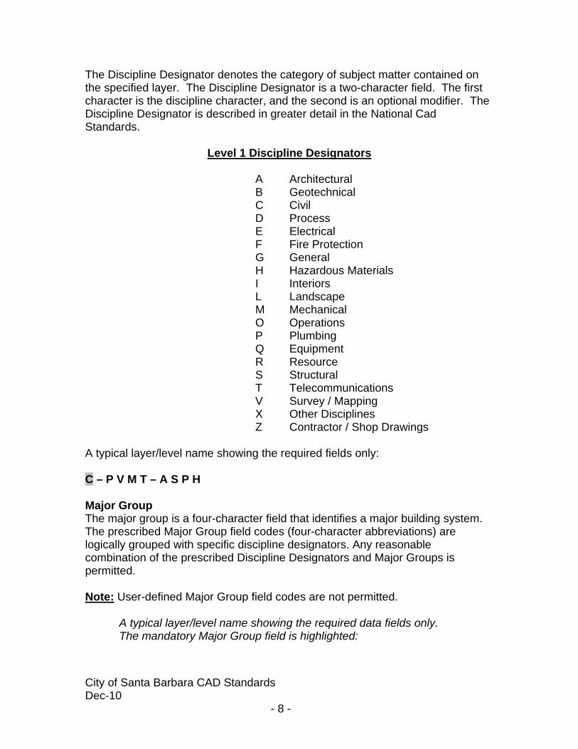
The Discipline Designator denotes the category of subject matter contained on the specified layer. The Discipline Designator is a two-character field. The first character is the discipline character, and the second is an optional modifier. The Discipline Designator is described in greater detail in the National Cad Standards.
Level 1 Discipline Designators A Architectural B Geotechnical C Civil D Process E Electrical F Fire Protection G General H Hazardous Materials I Interiors L Landscape M Mechanical O Operations P Plumbing Q Equipment R Resource S Structural T Telecommunications V Survey / Mapping X Other Disciplines Z Contractor / Shop Drawings
A typical layer/level name showing the required fields only: C – P V M T – A S P H Major Group The major group is a four-character field that identifies a major building system. The prescribed Major Group field codes (four-character abbreviations) are logically grouped with specific discipline designators. Any reasonable combination of the prescribed Discipline Designators and Major Groups is permitted. Note: User-defined Major Group field codes are not permitted.
A typical layer/level name showing the required data fields only. The mandatory Major Group field is highlighted:

City of Santa Barbara CAD Standards Dec-10
- 9 -
C – P V M T – A S P H A typical layer/level name showing two optional Minor Group fields: C – P V M T – A S P H – P A T T Status Field The status field is an optional single-character field that distinguishes the data contained on the layer/level according to the status of the work or the construction phase. The prescribed field codes for this field are as follows:
Status Field Codes A Items to be Abandoned D Items to be Demolished M Items to be Moved T Temporary Work
A typical layer/level name showing the location of the optional Status field: C – P V M T – A S P H – P A T T – T This concludes the excerpt from the ©National CAD Standards manual describing the layer/level naming format. Layer Manipulation Layers that are not required to be shown on a particular plan sheet should be “Frozen”. Turning layers “On” and “Off” interactively while editing a drawing file can save REGEN time and allow for easier editing. All layers/levels should be “On” before exiting or plotting a drawing file. Note: Layers that are “Frozen” or turned “Off” do not require REGEN time; “Thawing” a Layer will cause ©AutoCAD to REGEN.

City of Santa Barbara CAD Standards Dec-10
- 10 -
Section 4 – Project Elements History of Change:
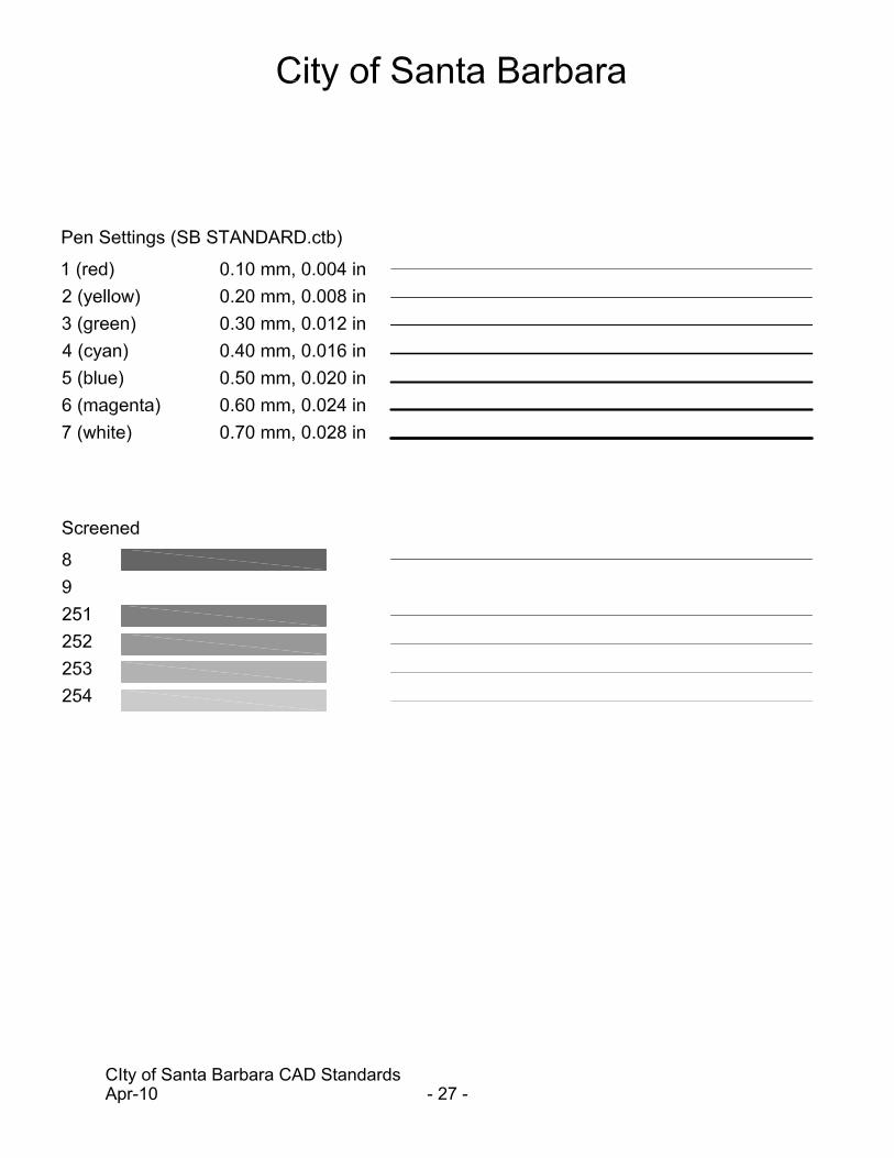
4.1 Pen Assignments The Pen Assignment for all drawings will be “SB Standard”. This Pen Setting is in the City of Santa Barbara Standard Template, available upon request. Refer to Appendix C for SB Standard Pen Setting Example.
Revision and Version
Author Date Change
1 ALS &MR 12/3/10 Initial Release of Manual
City of Santa Barbara CAD Standards Dec-10
- 11 -
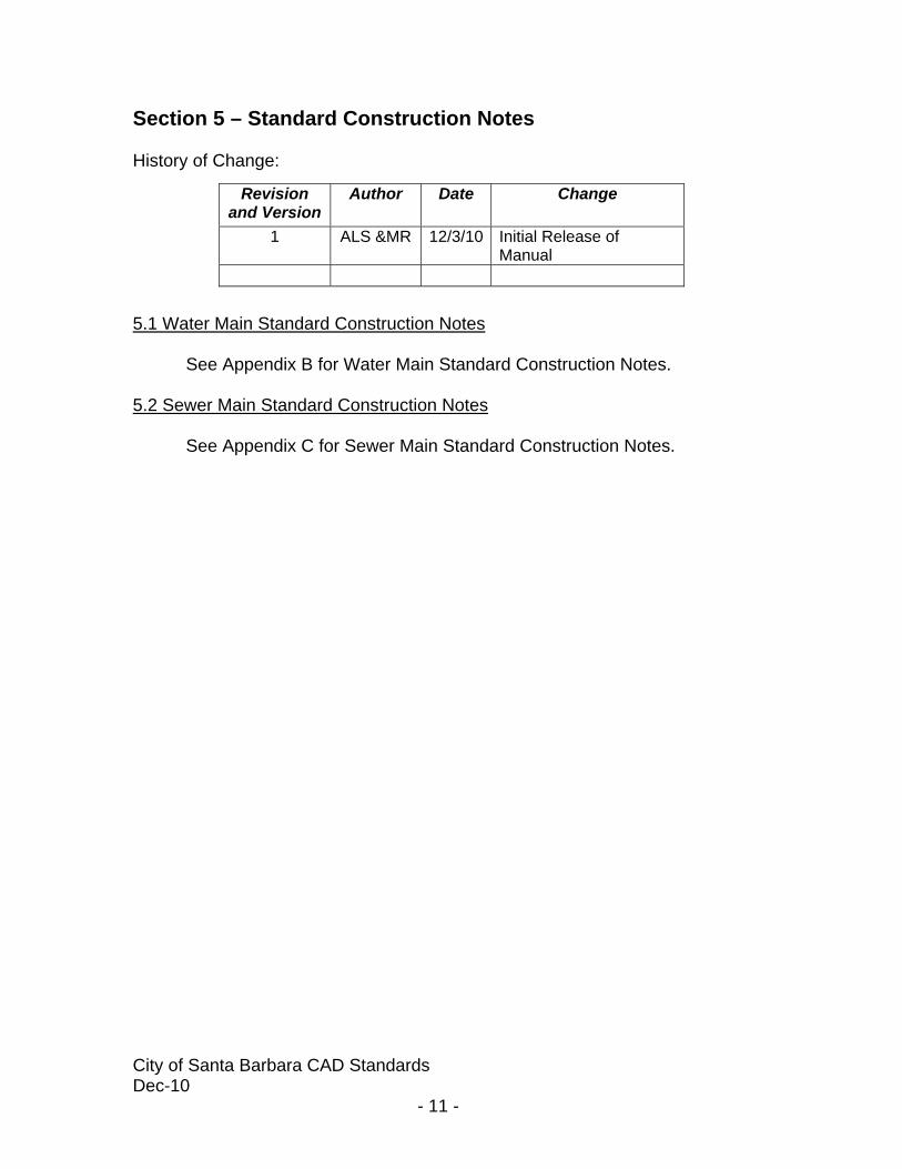
Section 5 – Standard Construction Notes History of Change: 5.1 Water Main Standard Construction Notes
See Appendix B for Water Main Standard Construction Notes. 5.2 Sewer Main Standard Construction Notes
See Appendix C for Sewer Main Standard Construction Notes.
Revision and Version
Author Date Change
1 ALS &MR 12/3/10 Initial Release of Manual

City of Santa Barbara CAD Standards Dec-10
- 12 -
Section 6 – Deliverables and Data Exchange
6.1 History of Change
This chapter describes the standard deliverables and data exchange formats required to exchange digital data (drawing files and database information) between the City of Santa Barbara and consultants.
6.2 Delivery Media
Digital media shall be delivered according to Table 6-1.
All digital media submissions will follow the City of Santa Barbara Cad Standards contained within this document. All digital plan files must be compatible with AutoCad 2009 or AutoDesk Civil 3D 2009. If the files are provided zipped, they must be zipped using a current version of WinZip. When digital media are exchanged, an external label must contain, at a minimum, the following information:
• Project Number and Bid Number (if applicable) • Project Title • Submittal Date
Revision and Version
Author Date Change
1 ALS &MR 12/3/10 Initial Release of Manual
Table 6-1 Submittal Media
Preliminary Design Report CD-ROM or Flash Drive Design Submittal 1 Design Submittal 2 Design Submittal 3 Final Design Submittal CD-ROM or Flash Drive Conformed Drawings CD-ROM or Flash Drive Record Drawings CD-ROM or Flash Drive

City of Santa Barbara CAD Standards Dec-10
- 13 -
• Consultant Name and Contact Person • Format and Version of the operating system on which the media was
created. • Sequence number (for multiple cd’s, etc.) • A short description of contents.
In addition, a transmittal sheet must accompany the media containing, at a minimum, the following information:
• Information included on the external label of each CD-ROM or Flash Drive.
• Total number of CD-ROMs being delivered. • List of filenames and file descriptions on each CD-ROM/Flash Drive. • Instruction for restoring/transferring the files from the media (if needed). • Certification that all delivery media is free of known viruses, including the
name of the virus scanning software used and the date the virus scan was performed.
Note: It shall be mutually understood that delivery of the digital data does not constitute a professional delivery of the contained drawing.
6.3 Data Format
All files necessary to produce the drawing set (base maps, project model files, etc.) shall be delivered in both native CAD format and as tiff images according to the
6.3.1 CAD Files All CAD files shall be delivered in a format that is directly readable and compatible with the City of Santa Barbara’s CAD Standards. Before a file is placed on a delivery media, the following procedures must be performed:
• Remove all extraneous graphics outside the border area. • Make sure all reference (external reference) files are
attached with the appropriate name variable and do not use device or directory specifications.
• Compress or purge all files using the appropriate utility. A digital media copy of the decompression utility should be provided with the deliverable media, if appropriate.
• Include all files, both graphic and non-graphic, required for the project (e.g., block libraries, user command files, etc.) All files should be created using the City of Santa Barbara CAD Standards (e.g., plot styles, color table, pen table, etc.). Prior authorization must be obtained from the Project Engineer to use non standard material.

City of Santa Barbara CAD Standards Dec-10
- 14 -
• Include all standard sheets (i.e. abbreviation sheets, standard symbol sheets, etc.) necessary for a complete project set.
6.4 Documentation
Unless otherwise specified in the project scope of work, the following media types will be submitted with the appropriate submittal as listed in Table 6-2.
Hardcopy media types must meet the following specifications:
• Bond is to be 20# white. • Vellum is to be 20# solvent-free rag vellum. • Mylar is to be 4mil double matte, with the drawing plotted reverse read.
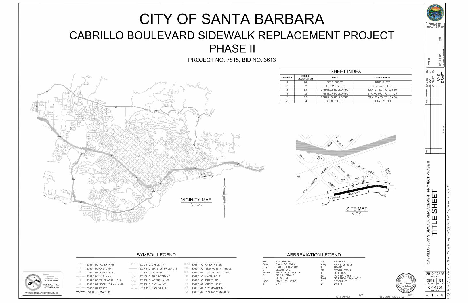
Section 7 – Record Drawings All record drawings shall contain the following (Refer to Appendix D for example sheets):
• City Engineer Original Sign Date • Record of Engineer Stamped and Signed • “RECORD DRAWING” shall be located on each sheet. Text shall be
Standard, Bold and 0.5” height. • All revision clouds shall be removed for final record drawing. Revision
clouds shall only be used for changes to construction drawings.
Table 6-2
Submittal Full Size/Media Half Size/
Media CAD Files PDF
Preliminary Design Report Bond Bond X X Design Submittal 1 Bond Bond Design Submittal 2 Bond Bond Design Submittal 3 Bond Bond Final Design Submittal Bond Bond X X Conformed Drawings Bond Bond X Record Drawings Mylar Bond X X

City of Santa Barbara CAD Standards Dec-10
- 15 -
Appendix A – Standard Layers
LAYER COLOR LINETYPE DESCRIPTION ?-ANNO-BRNG Green (3) Continuous Annotation: Bearings and Distance Labels (Survey Coordinates)?-ANNO-DIMS Yellow (2) Continuous Annotation: Dimensions ?-ANNO-KEYM Yellow (2) Continuous Annotation: Key Map ?-ANNO-KEYN Cyan (4) Continuous Annotation: Keynotes ?-ANNO-LABL Green (3) Continuous Annotation: Labels ?-ANNO-LEGN Cyan (4) Continuous Annotation: Legend and Symbol Keys ?-ANNO-LOTN Magenta (6) Continuous Annotation: Lot Numbers ?-ANNO-MASK 9 Continuous Annotation: Mask ?-ANNO-MATC Blue (5) Continuous Annotation: Match Lines ?-ANNO-NOTE Cyan (4) Continuous Annotation: Notes ?-ANNO-NPLT White (7) Continuous Annotation: Non-Plotting Graphic Information (Not Plotted) ?-ANNO-NRTH Cyan (4) Continuous Annotation: North Arrow ?-ANNO-PATT Red (1) Continuous Annotation: Pattern and Shadow Boxes ?-ANNO-RDME White (7) Continuous Annotation: Read-me Layer (Not Plotted) ?-ANNO-REFR White (7) Continuous Annotation: Reference and External Files ?-ANNO-REVC 252 Continuous Annotation: Revision Clouds ?-ANNO-SCAL Cyan (4) Continuous Annotation: Bar Scale ?-ANNO-SEAL Yellow (2) Continuous Annotation: Engineers Seal ?-ANNO-TEXT Green (3) Continuous Annotation: Text ?-ANNO-TITL Green (3) Continuous Annotation: Drawing or Detail Titles ?-ANNO-TTLB Green (3) Continuous Annotation: Border and Title Block ?-ANNO-VPRT Yellow (2) Continuous Annotation: Viewport ?-CNTR-STAN Green (3) Continuous Centerline: Stationing ?-SSWR-STAN Green (3) Continuous Sanitary Sewer: Stationing ?-STRM-STAN Green (3) Continuous Storm Sewer: Stationing ?-WATR-STAN Green (3) Continuous Water: Stationing C-AFLD-CRIT Green (3) Dashed Airfield: Critical Area C-AFLD-ERSA Green (3) Dashed Airfield: End of Runway Safety Area (ERSA) C-AFLD-PART Yellow (2) Hidden Airfield: Part 77 Surface C-AFLD-ROFA Green (3) Continuous Airfield: Runway Object Free Area (OFA) C-ARCH-LMTS Cyan (4) Dashed Archeological Sensitive Area: Limits C-BLDG-COLS Red (1) Hidden2 Buildings and Primary Structures: Columns C-BLDG-OTLN Blue (5) Continuous Buildings and Primary Structures: Outline C-BNDY-CITY White (7) Dashdot2 Political Boundaries: City C-BNDY-CNTY White (7) Dashdot2 Political Boundaries: County C-BRDG-CNTR Cyan (4) Center2 Bridge: Centerline C-BRDG-PATT Red (1) Continuous Bridge: Pattern C-CURB-FACE Yellow (2) Continuous Curb: Face of Curb C-GRAD-BRKL Green (3) Hidden Grading: Break and Fault Lines C-GRAD-LMTS Blue (5) Dashed Grading: Daylight Lines or Limits C-GRAD-PADS Green (3) Hidden Grading: Pads C-HTCH-ASPH 255 Continuous Hatch: Asphalt C-HTCH-CONC 254 Continuous Hatch: Concrete C-HTCH-PLNT 251 Continuous Hatch: Plant

City of Santa Barbara CAD Standards Dec-10
- 16 -
C-HTCH-RMVE 251 Continuous Hatch: Remove Existing Hardscape C-MRKG-WHIT White (7) Continuous Pavement Markings: White C-MRKG-YELO Yellow (2) Continuous Pavement Markings: Yellow C-PHAS-LINE White (7) Continuous Phasing: Phase Lines C-PROP-LINE Blue (5) Phantom2 Property: Property Lines C-PROP-LOTL Cyan (4) Continuous Property: Lot Lines C-PVMT-SAWC Blue (5) Phantom Pavements: Sawcut C-PVMT-ADCF Cyan (4) Dashed2 Pavements: Additional Conform C-PVMT-ASPH Cyan (4) Continuous Pavements: Asphalt Surface C-PVMT-CONC Cyan (4) Continuous Pavements: Concrete Surface C-RAMP-OUTL Magenta (6) Continuous Ramp: Outline C-RAMP-TRDM Red (1) Continuous Ramp: Truncated Domes C-RCLM-EQPM Yellow (2) Continuous Reclaimed Water: Equipment C-RCLM-MHOL Green (3) Continuous Reclaimed Water: Manhole C-RCLM-STAT Cyan (4) Continuous Reclaimed Water: Booster Station C-RCLM-STRC Green (3) Continuous Reclaimed Water: Structure C-RCLM-TANK Green (3) Continuous Reclaimed Water: Tank C-RCLM-UNDR Yellow (2) Use correct Size Reclaimed Water: Underground Lines C-ROAD-ASPH Cyan (4) Continuous Roadways: Asphalt Surface C-ROAD-CONC Cyan (4) Continuous Roadways: Concrete Surface C-SSWR-CLNO Cyan (4) Continuous Sanitary Sewer: Cleanout C-SSWR-EQPM Yellow (2) Continuous Sanitary Sewer: Equipment C-SSWR-FORC Green (3) Forc Sanitary Sewer: Force Main C-SSWR-LATL Yellow (2) Continuous Sanitary Sewer: Lateral or Service C-SSWR-MHOL Cyan (4) Continuous Sanitary Sewer: Manhole C-SSWR-OVHD Magenta (6) Ovhd Sanitary Sewer: Overhead Piping C-SSWR-STRC Cyan (4) Continuous Sanitary Sewer: Structure C-SSWR-UNDR Green (3) Sswr Sanitary Sewer: Underground Piping C-STRM-CNTR Hidden Storm Sewer: Centerline C-STRM-DETB Blue (5) Continuous Storm Sewer: Detention Basin C-STRM-DRNB Blue (5) Continuous Storm Sewer: Drainage Basin or Watershed Delineation C-STRM-EQPM Yellow (2) Continuous Storm Sewer: Equipment C-STRM-HWAL Cyan (4) Continuous Storm Sewer: Headwall C-STRM-HYGL Yellow (2) Hidden2 Storm Sewer: Hydraulic Grade Lines C-STRM-MHOL Cyan (4) Continuous Storm Sewer: Manhole C-STRM-STRC Cyan (4) Continuous Storm Sewer: Structure C-STRM-UNDR Cyan (4) Continuous Storm Sewer: Underground Piping C-SWLK-ASPH Cyan (4) Continuous Sidewalk: Asphalt Surface C-SWLK-CONC Cyan (4) Continuous Sidewalk: Concrete Surface C-SWLK-GRVL Green (3) Hidden Sidewalk: Gravel Surface C-SWLK-PATT Continuous Sidewalk: Pattern C-SWLK-RAMP Yellow (2) Continuous Sidewalk: Handicap Ramp C-TRAF-EQPM Yellow (2) Continuous Traffic: Equipment C-TRAF-POLE Yellow (2) Continuous Traffic: Pole C-TRSH-STRC Cyan (4) Continuous Trash: Structure C-VHCL-OTLN Cyan (4) Continuous Vehicle Turning Movements: Outline C-VHCL-SWEP Red (1) Hidden Vehicle Turning Movements: Swept Path

City of Santa Barbara CAD Standards Dec-10
- 17 -
C-VHCL-TIRE Red (1) Hidden2 Vehicle Turning Movements: Tire Path C-VHCL-WING Red (1) Hidden Vehicle Turning Movements: Wing Path C-WALL-RTWL Cyan (4) Continuous Walls: Retaining C-WATR-ENCS Yellow (2) Hidden2 Water: Encasement or Duct Bank C-WATR-EQPM Yellow (2) Continuous Water: Equipment C-WATR-LATL Yellow (2) Continuous Water: Lateral or Service C-WATR-STRC Cyan (4) Continuous Water: Structure C-WATR-TANK Cyan (4) Continuous Water: Storage Tank C-WATR-UNDR Blue (5) Watr Water: Underground Lines C-WATR-WELL Cyan (4) Continuous Water: Well C-WETL-LMTS Blue (5) Dashed Wetlands: Limits ?-DETL-CNTR Cyan (4) Center2 Detail: Centerline ?-DETL-MBND Yellow (2) Hidden2 Detail: Material Beyond ?-DETL-MCUT Green (3) Continuous Detail: Material Cut ?-DETL-OTLN Blue (5) Continuous Detail: Outline ?-DETL-PATT 253 Continuous Detail: Pattern ?-ELEV-CNTR Cyan (4) Center2 Elevation: Centerline ?-ELEV-MBND Yellow (2) Hidden2 Elevation: Material Beyond ?-ELEV-MCUT Green (3) Continuous Elevation: Material Cut ?-ELEV-OTLN Blue (5) Continuous Elevation: Outline ?-ELEV-PATT 253 Continuous Elevation: Pattern ?-SECT-CNTR Cyan (4) Center2 Section: Centerline ?-SECT-MBND Yellow (2) Hidden2 Section: Material Beyond ?-SECT-MCUT Green (3) Continuous Section: Material Cut ?-SECT-OTLN Blue (5) Continuous Section: Outline ?-SECT-PATT Red (1) Continuous Section: Pattern C-ANNO-EXST Red (1) Continuous Profile: Existing Annotation C-ANNO-GRID Red (1) Continuous Profile: Grid Annotation
C-PROF-EXST Yellow (2) Hidden Profile: Existing Grade
C-PROF-FNSH Blue (5) Continuous Profile: Finished Grade C-PROF-GRID 253 Continuous Profile: Grid Lines

City of Santa Barbara CAD Standards Dec-10
- 18 -
(THIS PAGE INTENTIONALLY LEFT BLANK)

City of Santa Barbara CAD Standards Dec-10
- 19 -
Appendix B Standard Water Resources Construction Notes

City of Santa Barbara CAD Standards Dec-10
- 20 -
(THIS PAGE INTENTIONALLY LEFT BLANK)

City of Santa Barbara CAD Standards Dec-10
- 21 -
Standard Sewer Main Construction Notes
LateralsRehabilitation 1.00 RECONNECT EXISTING ACTIVE SEWER LATERAL TO PROPOSED SEWER MAIN PER SPECIFICATIONS. (TYP. X)
1.101.201.30 RECONNECT EXISTING ACTIVE SEWER MAIN TO PROPOSED SEWER MAIN PER SPECIFICATIONS. (TYP. X)1.40
Replacement1.50 TIE OVER EXISTING ACTIVE SEWER LATERAL TO PROPOSED SEWER MAIN PER CITY CONSTRUCTION STANDARD
DETAIL 5-004.0. (TYP. X)1.60 REROUTE EXISTING SEWER LATERAL FROM R/W TO PROPOSED SEWER MAIN PER SPECIFICATIONS. (TYP. X)1.701.80 RECONSTRUCT LATERAL CONNECTION TO EXISTING SEWER MAIN PER SPECIFICATIONS (TYP. X)1.81 RECONNECT EXISTING LATERALS TO AN EXISTING CIPP REHABILITATED VCP MAIN LINE PER SPECIFICATIONS (TYP . 1.90
Point Repair2.00 POINT REPAIR PER SPECIFICATIONS. (TYP. X)2.102.202.302.402.50 ACCESS SEWER MANHOLE XXX-XXX THROUGH (PROPERTY ADDRESS) WITH APPROVAL OF HOMEOWNER AND
WASTEWATER COLLECTION SYSTEM SUPERINTENDENT.2.60 ACCESS SEWER CLEANOUT XXX-XXX THROUGH (PROPERTY ADDRESS) WITH APPROVAL OF HOMEOWNER AND
WASTEWATER COLLECTION SYSTEM SUPERINTENDENT.Manhole
Rehabilitate 3.00 REHABILITATE EXISTING MANHOLE PER SPECIFICATIONS. (TYP. X)3.10 REHABILITATE EXISTING DROP SEWER MANHOLE IN-PLACE. (TYP. X)3.20 RECONSTRUCT EXISTING MINI-SEWER MANHOLE PER DETAIL. (TYP. X) 3.30 RECONSTRUCT FLOOR OF MANHOLE TO REDIRECT FLOW PER DETAIL X. 3.31 LINE THROUGH SEWER MANHOLE. (TYP. X)3.32 RECONSTRUCT FLOOR OF MANHOLE TO ACCOMIDATE PROPOSED SEWER MAIN. (TYP. X)3.33 BULKHEAD AND REPAIR MANHOLE FOR PROPOSED ABANDONED INLET (TYP X.)3.40 PROTECT EXISTING SEWER MANHOLE IN-PLACE. (TYP. X)
Remove and Replace
3.50 REMOVE EXISTING SEWER MANHOLE. REPLACE WITH A PRECAST CONCRETE SEWER MANHOLE PER CITY CONSTRUCTION STANDARD DETAILS 5-001.0 & 5-001.1. (TYP. X)
3.60 REMOVE SEWER MANHOLE, BACKFILL AND REPLACE STREET STRUCTURAL SECTION PER SPECIFICATIONS. (TYP. New Construction 3.70 INSTALL NEW SEWER MANHOLE PER CITY STANDARD DETAILS 5-001.0 & 5-001.1. (TYP. X)
3.71 PER DETAIL X. 3.80 INSTALL NEW MINI-SEWER MANHOLE PER DETAIL X. (TYP. X)
Abandon 3.90 ABANDON EXISTING SEWER MANHOLE, BACKFILL, COMPACT, AND REPLACE STRUCTURAL SECTION PER SPECIFICATIONS. (TYP. X)
3.91 SLIP-LINE THROUGH SEWER MANHOLE. ABANDON EXISTING SEWER MANHOLE IN PLACE. BACKFILL, COMPACT, AND REPLACE STRUCTURAL SECTION PER SPECIFICATIONS.
3.92 ABANDON EXISTING SEWER MANHOLE, BREAK UP BOTTOM, REMOVE CONE, GRADE RINGS AND COVER, BACKFILL, COMPACT, AND REPLACE STREET SECTION. (TYP. X)
4" PipeRehabilitate 4.00 REHABILITATE XXX LF OF EXISTING 4-INCH VCP SEWER PIPE.
4.10 REHABILITATE XXX LF OF EXISTING 4-INCH CI SEWER PIPE.4.204.304.40
Remove and Replace
4.50 REMOVE EXISTING 4-INCH SEWER MAIN AND REPLACE WITH 4-INCH PVC SDR-35 SEWER PIPE. BACKFILL PER SPECIFICATIONS.
4.51 REMOVE EXISTING 4-INCH SEWER MAIN AND REPLACE WITH 8-INCH PVC SDR-35 SEWER PIPE. BACKFILL PER 4.60
New Construction 4.704.804.90

City of Santa Barbara CAD Standards Dec-10
- 22 -
Notes to the Contractor
5.00 RECONSTRUCT TRAFFIC LOOPS DAMAGED BY CONSTRUCTION PER SPECIFICATIONS. (TYP. X)5.10 ABANDON EXISTING SEWER MAIN PER SPECIFICATION5.15 ABANDON EXISTING SEWER LATERAL PER SPECIFICATIONS5.20 PROTECT EXISTING SEWER MAIN IN-PLACE.5.305.40
Pipe Bursting 5.50 INCHES. 6" Pipe
Rehabilitate 6.00 REHABILITATE XXX LF OF EXISTING 6-INCH VCP SEWER PIPE.6.10 REHABILITATE XXX LF OF EXISTING 6-INCH CI SEWER PIPE.6.206.30 MECHANICALLY CLEAN XXX LF OF 6-INCH CI SEWER MAIN BEFORE SLIP LINING. 6.40
Remove and Replace
6.50 REMOVE EXISTING 6-INCH SEWER MAIN AND REPLACE WITH 6-INCH PVC SDR-35 SEWER PIPE. BACKFILL PER SPECIFICATIONS.
6.51 REMOVE EXISTING 4-INCH SEWER MAIN AND REPLACE WITH 6-INCH PVC SDR-35 SEWER PIPE. BACKFILL PER SPECIFICATIONS.
6.60New Construction 6.70 INSTALL 6-INCH PVC SDR-35 SEWER PIPE. BACK FILL PER SPECIFICATIONS.
6.806.90
Sewer Cleanout
7.00 REMOVE EXISTING SEWER CLEANOUT. (TYP. X)7.10 INSTALL PROPOSED 8-INCH SEWER CLEANOUT PER CITY STANDARD DETAIL 5-003.0. (TYP. X)7.15 INSTALL PROPOSED 4-INCH RESIDENTIAL SEWER CLEANOUT PER SPECIFICATIONS.7.20 LINE THROUGH SEWER CLEAN OUT. (TYP. X)7.30 REMOVE EXISTING SEWER CLEANOUT AND INSTALL PROPOSED 4-INCH HDPE RESIDENTIAL SEWER CLEANOUT PER
DETAIL ON THIS SHEET. (TYP. X)7.40
Fittings 7.507.607.707.807.90
8" PipeRehabilitate 8.00 REHABILITATE XXX LF OF EXISTING 8-INCH VCP SEWER PIPE.
8.10 REHABILITATE XXX LF OF EXISTING 8-INCH CI SEWER PIPE.8.208.30 MECHANICALLY CLEAN XXX LF OF 8-INCH CI SEWER MAIN BEFORE SLIP LINING. 8.40
Remove and Replace
8.50 REMOVE EXISTING 8-INCH SEWER MAIN AND REPLACE WITH 8-INCH PVC SDR-35 SEWER PIPE. BACKFILL PER SPECIFICATIONS.
8.51 REMOVE EXISTING 6-INCH SEWER MAIN AND REPLACE WITH 8-INCH PVC SDR-35 SEWER PIPE. BACKFILL PER SPECIFICATIONS.
8.52 REMOVE EXISTING 4-INCH SEWER MAIN AND REPLACE WITH 8-INCH PVC SDR-35 SEWER PIPE. BACKFILL PER SPECIFICATIONS.
8.538.548.558.60 REMOVE EXISTING SEWER MAIN AS NECESSARY TO INSTALL 8-INCH HDPE SDR-26 SEWER PIPE. BACKFILL PER
SPECIFICATIONS.New Construction 8.70 INSTALL 8-INCH PVC SDR-35 SEWER PIPE. BACK FILL PER SPECIFICATIONS
8.80 INSTALL 8-INCH SDR-26 HDPE SEWER PIPE. BACK FILL PER SPECIFICATIONS8.90
10" PipeRehabilitate 10.00 REHABILITATE XXX LF OF EXISTING 10-INCH VCP SEWER PIPE.
10.10 REHABILITATE XXX LF OF EXISTING 10-INCH CI SEWER PIPE.10.2010.30 MECHANICALLY CLEAN XXX LF OF 10-INCH CI SEWER MAIN BEFORE SLIP LINING. 10.40
Remove and Replace
10.50 REMOVE EXISTING 10-INCH SEWER MAIN AND REPLACE WITH 8-INCH PVC SDR-35 SEWER PIPE. BACKFILL PER SPECIFICATIONS.
10.51 REMOVE EXISTING 8-INCH SEWER MAIN AND REPLACE WITH 8-INCH PVC SDR-35 SEWER PIPE. BACKFILL PER 10.52 REMOVE EXISTING 4-INCH SEWER MAIN AND REPLACE WITH 8-INCH PVC SDR-35 SEWER PIPE. BACKFILL PER 10.53 REMOVE EXISTING 12-INCH SEWER MAIN AND REPLACE WITH 8-INCH PVC SDR-35 SEWER PIPE. BACKFILL PER 10.60 REMOVE EXISTING SEWER MAIN AS NECESSARY TO INSTALL 10-INCH HDPE SDR-26 SEWER PIPE. BACKFILL PER
New Construction 10.70 INSTALL 10-INCH PVC SDR-35 SEWER PIPE. BACK FILL PER SPECIFICATIONS10.80 INSTALL 10-INCH SDR-26 HDPE SEWER PIPE. BACK FILL PER SPECIFICATIONS10.90
City of Santa Barbara CAD Standards Dec-10
- 23 -
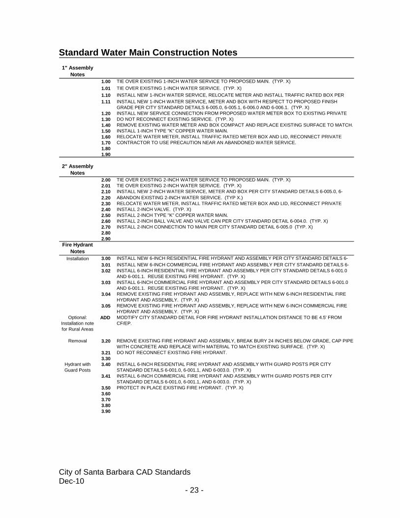
Standard Water Main Construction Notes 1" Assembly
Notes1.00 TIE OVER EXISTING 1-INCH WATER SERVICE TO PROPOSED MAIN. (TYP. X)1.01 TIE OVER EXISTING 1-INCH WATER SERVICE. (TYP. X)1.10 INSTALL NEW 1-INCH WATER SERVICE, RELOCATE METER AND INSTALL TRAFFIC RATED BOX PER 1.11 INSTALL NEW 1-INCH WATER SERVICE, METER AND BOX WITH RESPECT TO PROPOSED FINISH
GRADE PER CITY STANDARD DETAILS 6-005.0, 6-005.1, 6-006.0 AND 6-006.1. (TYP. X)1.20 INSTALL NEW SERVICE CONNECTION FROM PROPOSED WATER METER BOX TO EXISTING PRIVATE 1.30 DO NOT RECONNECT EXISTING SERVICE. (TYP. X)1.40 REMOVE EXISTING WATER METER AND BOX COMPACT AND REPLACE EXISTING SURFACE TO MATCH. 1.50 INSTALL 1-INCH TYPE "K" COPPER WATER MAIN.1.60 RELOCATE WATER METER, INSTALL TRAFFIC RATED METER BOX AND LID, RECONNECT PRIVATE 1.70 CONTRACTOR TO USE PRECAUTION NEAR AN ABANDONED WATER SERVICE. 1.801.90
2" Assembly Notes
2.00 TIE OVER EXISTING 2-INCH WATER SERVICE TO PROPOSED MAIN. (TYP. X)2.01 TIE OVER EXISTING 2-INCH WATER SERVICE. (TYP. X)2.10 INSTALL NEW 2-INCH WATER SERVICE, METER AND BOX PER CITY STANDARD DETAILS 6-005.0, 6-2.20 ABANDON EXISTING 2-INCH WATER SERVICE. (TYP X.)2.30 RELOCATE WATER METER, INSTALL TRAFFIC RATED METER BOX AND LID, RECONNECT PRIVATE 2.40 INSTALL 2-INCH VALVE. (TYP. X)2.50 INSTALL 2-INCH TYPE "K" COPPER WATER MAIN. 2.60 INSTALL 2-INCH BALL VALVE AND VALVE CAN PER CITY STANDARD DETAIL 6-004.0. (TYP. X)2.70 INSTALL 2-INCH CONNECTION TO MAIN PER CITY STANDARD DETAIL 6-005.0 (TYP. X)2.802.90
Fire Hydrant Notes
Installation 3.00 INSTALL NEW 6-INCH RESIDENTIAL FIRE HYDRANT AND ASSEMBLY PER CITY STANDARD DETAILS 6-3.01 INSTALL NEW 6-INCH COMMERCIAL FIRE HYDRANT AND ASSEMBLY PER CITY STANDARD DETAILS 6-3.02 INSTALL 6-INCH RESIDENTIAL FIRE HYDRANT AND ASSEMBLY PER CITY STANDARD DETAILS 6-001.0
AND 6-001.1. REUSE EXISTING FIRE HYDRANT. (TYP. X)3.03 INSTALL 6-INCH COMMERCIAL FIRE HYDRANT AND ASSEMBLY PER CITY STANDARD DETAILS 6-001.0
AND 6-001.1. REUSE EXISTING FIRE HYDRANT. (TYP. X)3.04 REMOVE EXISTING FIRE HYDRANT AND ASSEMBLY, REPLACE WITH NEW 6-INCH RESIDENTIAL FIRE
HYDRANT AND ASSEMBLY. (TYP. X)3.05 REMOVE EXISTING FIRE HYDRANT AND ASSEMBLY, REPLACE WITH NEW 6-INCH COMMERCIAL FIRE
HYDRANT AND ASSEMBLY. (TYP. X)Optional:
Installation note for Rural Areas
ADD MODTIFY CITY STANDARD DETAIL FOR FIRE HYDRANT INSTALLATION DISTANCE TO BE 4.5' FROM CF/EP.
Removal 3.20 REMOVE EXISTING FIRE HYDRANT AND ASSEMBLY, BREAK BURY 24 INCHES BELOW GRADE, CAP PIPE WITH CONCRETE AND REPLACE WITH MATERIAL TO MATCH EXISTING SURFACE. (TYP. X)
3.21 DO NOT RECONNECT EXISTING FIRE HYDRANT. 3.30
Hydrant with Guard Posts
3.40 INSTALL 6-INCH RESIDENTIAL FIRE HYDRANT AND ASSEMBLY WITH GUARD POSTS PER CITY STANDARD DETAILS 6-001.0, 6-001.1, AND 6-003.0. (TYP. X)
3.41 INSTALL 6-INCH COMMERCIAL FIRE HYDRANT AND ASSEMBLY WITH GUARD POSTS PER CITY STANDARD DETAILS 6-001.0, 6-001.1, AND 6-003.0. (TYP. X)
3.50 PROTECT IN PLACE EXISTING FIRE HYDRANT. (TYP. X)3.603.703.803.90

City of Santa Barbara CAD Standards Dec-10
- 24 -
4" Assembly Notes
Pipe Material 4.00 INSTALL 4-INCH PVC C900 CLASS 200 WATER PIPE.4.01 INSTALL 4-INCH DI CLASS 350 WATER PIPE.
Valve 4.10 INSTALL 4-INCH MJ WATER VALVE WITH LOCKING RETAINER GLANDS. (TYP. X)4.11 INSTALL 4-INCH MJ WATER VALVE WITH LOCKING RETAINER GLANDS AND 1.5+/- LF 4-INCH DI PIPE
BETWEEN THE VALVE AND TEE. (TYP. X). 4.12 INSTALL 4-INCH MJ WATER VALVE WITH LOCKING RETAINER GLANDS AND 1.5+/- LF 4-INCH DI PIPE
BETWEEN THE VALVE AND CROSS. (TYP. X). Tee 4.20 INSTALL 4-INCH x 4-INCH DI MJ TEE WITH LOCKING RETAINER GLANDS AND THRUST BLOCK. (TYP. X)
4.21 REMOVE EXISTING TEE, INSTALL 4-INCH x 4-INCH DI MJ TEE WITH LOCKING RETAINER GLANDS AND Cross 4.30 INSTALL 4-INCH x 4-INCH DI MJ CROSS WITH LOCKING RETAINER GLANDS. (TYP. X)Bend 4.40 INSTALL 4-INCH x 45 DEGREE DI MJ BEND, WITH LOCKING RETAINER GLANDS AND THRUST BLOCK.
4.41 INSTALL 4-INCH x 22.5 DEGREE DI MJ BEND, WITH LOCKING RETAINER GLANDS AND THRUST BLOCK. 4.42 INSTALL 4-INCH x 11.25 DEGREE DI MJ BEND, WITH LOCKING RETAINER GLANDS AND THRUST BLOCK.
Coupling 4.50 INSTALL 4-INCH x 12-INCH LONG SOLID SLEEVE COUPLING WITH LOCKING RETAINER GLANDS. (TYP. 4.51 INSTALL 4-INCH x 12-INCH LONG SOLID SLEEVE COUPLING WITH LOCKING RETAINER GLANDS AND
1.5+/- LF 4-INCH DI PIPE BETWEEN COUPLING AND VALVE. (TYP. X)4.52 INSTALL 1.5+/- LF OF 4-INCH DI PIPE OR AN APPROVED EQUAL, BETWEEN VALVE AND TEE. (TYP. X)4.53 INSTALL 1.5+/- LF OF 4-INCH DI PIPE OR AN APPROVED EQUAL, BETWEEN VALVE AND CROSS. (TYP. 4.54 INSTALL 1.5+/- LF OF 4-INCH DI PIPE OR AN APPROVED EQUAL, BETWEEN VALVE AND REDUCER. 4.55 INSTALL 1.5+/- LF OF 4-INCH DI PIPE OR AN APPROVED EQUAL, BETWEEN VALVE AND BEND. (TYP. X)
Reducer 4.604.614.624.704.804.90
General Notes To
Contractor5.00 CONTRACTOR SHALL CONTACT WATER RESOURCES BEFORE CUTTING AND CAPPING EXISTING 5.10 CONTRACTOR SHALL SUBMIT A HIGH-LINE PLAN TO THE CITY OF SANTA BARBARA WATER
RESOURCES DEPARTMENT PRIOR TO CONSTRUCTION.5.11 CONTRACTOR SHALL HIGH-LINE ALL SERVICES TO BE WITHOUT WATER BEYOND NORMAL WORK 5.20 ABANDON EXISTING WATER MAIN IN PLACE.5.21 PROTECT IN PLACE, TO REMAIN IN SERVICE UNTIL PROPOSED MAIN HAS BEEN TIED-OVER
Remove5.30 REMOVE EXISTING VALVE BOX, BACKFILL, COMPACT, AND REPLACE PAVEMENT SECTION TO MATCH
EXISTING SURFACE. (TYP. X)5.31 REMOVE AND REPLACE PLASTIC SERVICE CONNECTION WITH COPPER. (TYP. X)5.32 REMOVE EXISTING MAIN AS NECESSARY FOR INSTALLATION OF PROPOSED MAIN, CAP EXISTING 5.33 REMOVE EXISTING VALVE, PLUG TEE, BACKFILL, COMPACT, AND REPLACE PAVEMENT SECTION TO 5.40 REMOVE EXISTING MAIN AND INSTALL PROPOSED IN THE EXISTING MAIN ALIGNMENT
Landscape 5.50 PROTECT IN PLACE EXISTING LANDSCAPING.5.51 PROTECT IN PLACE EXISTING SURVEY MONUMENT.5.525.60 REMOVE CONCRETE GUTTER BACK TO 1.5 FEET FROM CURB FACE FOR WATER MAIN INSTALLATION.
REPLACE THE REMOVED CONCRETE GUTTER WITH A.C. 5.61 RECONSTRUCT SURFACE TO MATCH EXISTING MATERIAL AND CROSS-SECTION.
Special Backfill 5.70 USE A FULL DEPTH 2-SACK SLURRY BACKFILL FOR ALL TRENCH WORK IN THE HATCHED AREA.Water / Sewer
Seperation5.80 RECONSTRUCT SEWER MAIN TO COMPLY WITH CITY STANDARD DETAILS 7-003.1 & 7-003.2.

City of Santa Barbara CAD Standards Dec-10
- 25 -
Appendix C SB Standard Pen Assignments

City of Santa Barbara CAD Standards Dec-10
- 26 -
(THIS PAGE INTENTIONALLY LEFT BLANK)
CIty of Santa Barbara CAD StandardsApr-10 - 27 -

CIty of Santa Barbara CAD StandardsApr-10 - 28 -

City of Santa Barbara CAD Standards Dec-10
- 29 -
Appendix D Example Sheets