Embed Size (px)
Citation preview

The City of New York Department of Environmental Protection
Emily Lloyd Commissioner
Bureau of Environmental Planning & Analysis
ENVIRONMENTAL ASSESSMENT ATTACHMENT 1
PROJECT DESCRIPTION
JULY 2008
Prepared by:
/A Joint Venture
ATTACHMENT 1. PROJECT DESCRIPTION TABLE OF CONTENTS
1 INTRODUCTION AND PROJECT BACKGROUND ............................................. 3 1.1 INTRODUCTION .............................................................................................. 3 1.2 AUTHORITY ..................................................................................................... 3 1.3 NEED FOR THE PROPOSED PROJECT.......................................................... 4 1.4 BACKGROUND ................................................................................................ 5
1.4.1 NYC Water Supply System ........................................................................... 5 1.4.1.1 Catskill Water Supply System ................................................................ 5 1.4.1.2 Schoharie Reservoir ................................................................................ 8 1.4.1.3 Gilboa Dam........................................................................................... 10
1.4.2 Gilboa Dam Emergency Work..................................................................... 12 1.5 PROJECT DESCRIPTION............................................................................... 14
1.5.1 Reconstruction Engineering and Design Analysis....................................... 15 1.5.1.1 Dam Reconstruction.............................................................................. 15 1.5.1.2 Low Level Outlet (LLO)....................................................................... 22 1.5.1.3 Snowpack-Based Reservoir Management/Spillway Notch .................. 27
1.5.2 Construction Work Site and Staging Area................................................... 33 1.5.3 Construction Site Access ............................................................................. 34
1.5.3.1 Road 16 ................................................................................................. 34 1.5.3.2 West Access Road................................................................................. 35 1.5.3.3 West Training Wall Access Road......................................................... 38 1.5.3.4 Road 8 ................................................................................................... 38
1.5.4 Spoils Disposal Area and Temporary Internal Bridge................................. 38 1.5.5 Gilboa Dam Reconstruction......................................................................... 38
1.5.5.1 Crest Gates ............................................................................................ 38 1.5.5.2 West Training Wall............................................................................... 39 1.5.5.3 North Training Wall Berm.................................................................... 39 1.5.5.4 Masonry Reconstruction ....................................................................... 39 1.5.5.5 Low Level Outlet (LLO)....................................................................... 40 1.5.5.6 Upper Gate Chamber ............................................................................ 40 1.5.5.7 Earthfill Embankment Dam .................................................................. 40
1.5.6 Scenic Public Overlook Area....................................................................... 40 1.5.7 Shandaken Tunnel Intake Facility Rehabilitation........................................ 41 1.5.8 Site Restoration............................................................................................ 41 1.5.9 Construction Phasing ................................................................................... 41 1.5.10 Reasonable Worst Case Scenario................................................................. 44 1.5.11 Construction Provisions ............................................................................... 44
1.5.11.1 Best Management Practices – Air Emissions ....................................... 46 1.5.11.2 Best Management Practices – Noise..................................................... 46
1.5.12 Permits and Approvals................................................................................. 47
LIST OF FIGURES
Figure 1-1: New York City Water Supply System ............................................................. 6 Figure 1-2: Catskill Water Supply System ......................................................................... 7 Figure 1-3: Schoharie Reservoir ......................................................................................... 9 Figure 1-4: Gilboa Dam.................................................................................................... 10 Figure 1-5: Gilboa Dam.................................................................................................... 11 Figure 1-6: Façade Deterioration ...................................................................................... 12 Figure 1-7: Emergency Work ........................................................................................... 14 Figure 1-8: 1:20 Model ..................................................................................................... 17 Figure 1-9: 1:40 Model ..................................................................................................... 18 Figure 1-10: Landslide Prone Area................................................................................... 20 Figure 1-11: Proposed Spillway Stair-Step Configuration ............................................... 21 Figure 1-12: Existing Low Level Outlet........................................................................... 23 Figure 1-13: Low Level Outlet Alternatives Under Evaluation ....................................... 26 Figure 1-14: Conceptual Rendering of Crest Gates.......................................................... 31 Figure 1-15: Typical Installation of Crest Gates............................................................... 32 Figure 1-16: Proposed Crest Gate System Installation at Gilboa Dam ............................ 32 Figure 1-17: Gilboa Dam Reconstruction Work Site and Staging Area........................... 36 Figure 1-18: Overall Temporary Erosion Control Plan .................................................... 37 Figure 1-19: Staging for Site Preparation Gilboa Dam and Associated Facilities .......... 43
LIST OF TABLES
Table 1-1: Low Level Outlet ALTERNATIVES UNDER EVALUATION.................... 27 Table 1-2: HIGHEST RECORDED STREAMFLOWS AT SCHOHARIE CREEK DOWNSTREAM OF GILBOA DAM (1936-PRESENT) ............................................... 29 Table 1-3: EFFECTS OF SNOWPACK-based reservoir management FOR RAIN ON SNOW EVENTS .............................................................................................................. 30 Table 1-4: Possible Discretionary Permits and Approvals ............................................... 48
3
1 INTRODUCTION AND PROJECT BACKGROUND
1.1 INTRODUCTION
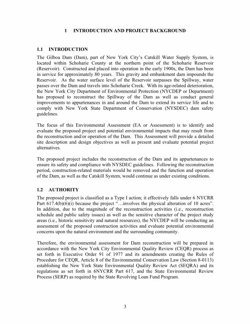
The Gilboa Dam (Dam), part of New York City’s Catskill Water Supply System, is located within Schoharie County at the northern point of the Schoharie Reservoir (Reservoir). Constructed and placed into operation in the early 1900s, the Dam has been in service for approximately 80 years. This gravity and embankment dam impounds the Reservoir. As the water surface level of the Reservoir surpasses the Spillway, water passes over the Dam and travels into Schoharie Creek. With its age-related deterioration, the New York City Department of Environmental Protection (NYCDEP or Department) has proposed to reconstruct the Spillway of the Dam as well as conduct general improvements to appurtenances in and around the Dam to extend its service life and to comply with New York State Department of Conservation (NYSDEC) dam safety guidelines.
The focus of this Environmental Assessment (EA or Assessment) is to identify and evaluate the proposed project and potential environmental impacts that may result from the reconstruction and/or operation of the Dam. This Assessment will provide a detailed site description and design objectives as well as present and evaluate potential project alternatives.
The proposed project includes the reconstruction of the Dam and its appurtenances to ensure its safety and compliance with NYSDEC guidelines. Following the reconstruction period, construction-related materials would be removed and the function and operation of the Dam, as well as the Catskill System, would continue as under existing conditions.
1.2 AUTHORITY
The proposed project is classified as a Type I action; it effectively falls under 6 NYCRR Part 617.4(b)(6)(i) because the project “…involves the physical alteration of 10 acres”. In addition, due to the magnitude of the reconstruction activities (i.e., reconstruction schedule and public safety issues) as well as the sensitive character of the project study areas (i.e., historic sensitivity and natural resources), the NYCDEP will be conducting an assessment of the proposed construction activities and evaluate potential environmental concerns upon the natural environment and the surrounding community.
Therefore, the environmental assessment for Dam reconstruction will be prepared in accordance with the New York City Environmental Quality Review (CEQR) process as set forth in Executive Order 91 of 1977 and its amendments creating the Rules of Procedure for CEQR, Article 8 of the Environmental Conservation Law (Section 8-0113) establishing the New York State Environmental Quality Review Act (SEQRA) and its regulations as set forth in 6NYCRR Part 617, and the State Environmental Review Process (SERP) as required by the State Revolving Loan Fund Program.
4
1.3 NEED FOR THE PROPOSED PROJECT
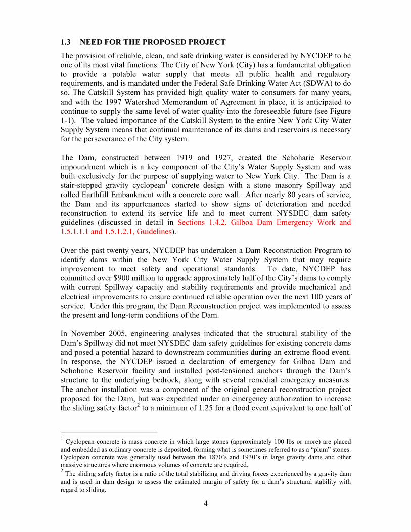
The provision of reliable, clean, and safe drinking water is considered by NYCDEP to be one of its most vital functions. The City of New York (City) has a fundamental obligation to provide a potable water supply that meets all public health and regulatory requirements, and is mandated under the Federal Safe Drinking Water Act (SDWA) to do so. The Catskill System has provided high quality water to consumers for many years, and with the 1997 Watershed Memorandum of Agreement in place, it is anticipated to continue to supply the same level of water quality into the foreseeable future (see Figure 1-1). The valued importance of the Catskill System to the entire New York City Water Supply System means that continual maintenance of its dams and reservoirs is necessary for the perseverance of the City system.
The Dam, constructed between 1919 and 1927, created the Schoharie Reservoir impoundment which is a key component of the City’s Water Supply System and was built exclusively for the purpose of supplying water to New York City. The Dam is a stair-stepped gravity cyclopean1 concrete design with a stone masonry Spillway and rolled Earthfill Embankment with a concrete core wall. After nearly 80 years of service, the Dam and its appurtenances started to show signs of deterioration and needed reconstruction to extend its service life and to meet current NYSDEC dam safety guidelines (discussed in detail in Sections 1.4.2, Gilboa Dam Emergency Work and 1.5.1.1.1 and 1.5.1.2.1, Guidelines).
Over the past twenty years, NYCDEP has undertaken a Dam Reconstruction Program to identify dams within the New York City Water Supply System that may require improvement to meet safety and operational standards. To date, NYCDEP has committed over $900 million to upgrade approximately half of the City’s dams to comply with current Spillway capacity and stability requirements and provide mechanical and electrical improvements to ensure continued reliable operation over the next 100 years of service. Under this program, the Dam Reconstruction project was implemented to assess the present and long-term conditions of the Dam.
In November 2005, engineering analyses indicated that the structural stability of the Dam’s Spillway did not meet NYSDEC dam safety guidelines for existing concrete dams and posed a potential hazard to downstream communities during an extreme flood event. In response, the NYCDEP issued a declaration of emergency for Gilboa Dam and Schoharie Reservoir facility and installed post-tensioned anchors through the Dam’s structure to the underlying bedrock, along with several remedial emergency measures. The anchor installation was a component of the original general reconstruction project proposed for the Dam, but was expedited under an emergency authorization to increase the sliding safety factor2 to a minimum of 1.25 for a flood event equivalent to one half of
1 Cyclopean concrete is mass concrete in which large stones (approximately 100 lbs or more) are placed and embedded as ordinary concrete is deposited, forming what is sometimes referred to as a “plum” stones. Cyclopean concrete was generally used between the 1870’s and 1930’s in large gravity dams and other massive structures where enormous volumes of concrete are required. 2 The sliding safety factor is a ratio of the total stabilizing and driving forces experienced by a gravity dam and is used in dam design to assess the estimated margin of safety for a dam’s structural stability with regard to sliding.
5
the Probable Maximum Flood (PMF3). The remaining Dam reconstruction work is now focused on addressing the deterioration of the stone façade, improving the Dam’s long term hydraulic performance, providing a functioning reservoir drain through the installation of a new Low Level Outlet (LLO), and enhancing downstream flood attenuation (snowpack based reservoir management) through the installation of crest gates into an existing Spillway notch installed during the 2006 anchor installation. Upon completion of the remaining proposed reconstruction work, the Gilboa Dam and Schoharie Reservoir would be in compliance with the current NYSDEC dam safety guidelines and ensure its continued long-term reliability in the New York City Water Supply System.
1.4 BACKGROUND
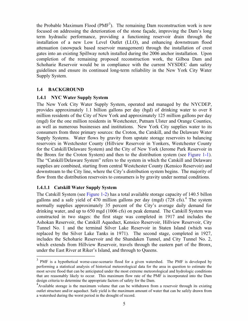
1.4.1 NYC Water Supply System The New York City Water Supply System, operated and managed by the NYCDEP, provides approximately 1.1 billion gallons per day (bgd) of drinking water to over 8 million residents of the City of New York and approximately 125 million gallons per day (mgd) for the one million residents in Westchester, Putnam Ulster and Orange Counties, as well as numerous businesses and institutions. New York City supplies water to its consumers from three primary sources: the Croton, the Catskill, and the Delaware Water Supply Systems. Water flows by gravity from upstate storage reservoirs to balancing reservoirs in Westchester County (Hillview Reservoir in Yonkers, Westchester County for the Catskill/Delaware System) and the City of New York (Jerome Park Reservoir in the Bronx for the Croton System) and then to the distribution system (see Figure 1-1).The “Catskill/Delaware System” refers to the system in which the Catskill and Delaware supplies are combined, starting from central Westchester County (Kensico Reservoir) and downstream to the City line, where the City’s distribution system begins. The majority of flow from the distribution reservoirs to consumers is by gravity under normal conditions.
1.4.1.1 Catskill Water Supply System The Catskill System (see Figure 1-2) has a total available storage capacity of 140.5 billon gallons and a safe yield of 470 million gallons per day (mgd) (728 cfs).4 The system normally supplies approximately 35 percent of the City’s average daily demand for drinking water, and up to 650 mgd (1006 cfs) on peak demand. The Catskill System was constructed in two stages: the first stage was completed in 1917 and includes the Ashokan Reservoir, the Catskill Aqueduct, Kensico Reservoir, Hillview Reservoir, City Tunnel No. 1 and the terminal Silver Lake Reservoir in Staten Island (which was replaced by the Silver Lake Tanks in 1971). The second stage, completed in 1927, includes the Schoharie Reservoir and the Shandaken Tunnel, and City Tunnel No. 2, which extends from Hillview Reservoir, travels through the eastern part of the Bronx, under the East River at Riker’s Island, and through to Queens.
3 PMF is a hypothetical worse-case-scenario flood for a given watershed. The PMF is developed by performing a statistical analysis of historical meteorological data for the area in question to estimate the most severe flood that can be anticipated under the most extreme meteorological and hydrologic conditions that are reasonably likely to occur. This maximum flow rate of the PMF is incorporated into the Dam design criteria to determine the appropriate factors of safety for the Dam. 4Available storage is the maximum volume that can be withdrawn from a reservoir through its existing outlet structure and/or aqueduct. Safe yield is the maximum amount of water that can be safely drawn from a watershed during the worst period in the drought of record.
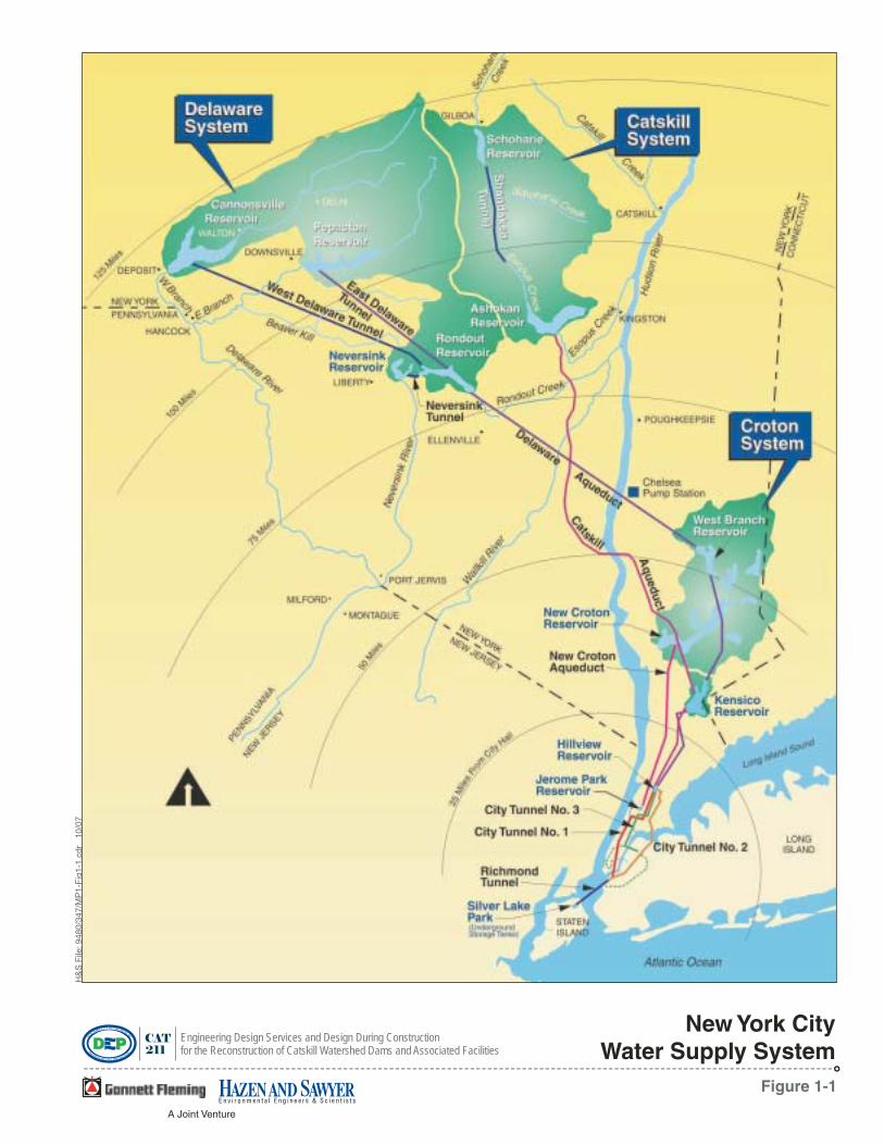
Figure 1-1
H&
SF
ile:9
480/
347/
MP
1-F
ig1-
1.cd
r10
/07
New York CityWater Supply System
A Joint Venture
CAT
211
Engineering Design Services and Design During Constructionfor the Reconstruction of Catskill Watershed Dams and Associated Facilities
Figure 1-2
H&
SF
ile:9
480/
400/
MP
1-F
ig1-
2.cd
r10
/07
Schoharie Creek
Bear Kill
EsopusCreek
EsopusCreek
West Kill
East Kill
Batavia Kill
SchoharieCreek
SchoharieReservoir
AshokanReservoir
CatskillWatershed
CatskillAqueduct
ShandakenTunnel
ShandakenDischarge
ShandakenIntake
Catskill SystemWest of Hudson
A Joint Venture
CAT
211
Engineering Design Services and Design During Constructionfor the Reconstruction of Catskill Watershed Dams and Associated Facilities
8
Water from the Catskill System comes from the watersheds of the Esopus and Schoharie Creeks, centered approximately 100 miles north of lower Manhattan and 35 miles west of the Hudson River. The Esopus Creek, which flows naturally into the Hudson River, is impounded by the Ashokan Reservoir, which has a watershed area of 257 square miles. The Schoharie Creek, which drains into the Mohawk River, is impounded by the Schoharie Reservoir, which has a watershed area of 314 square miles. Water in the Catskill System is transferred from the Schoharie Reservoir to the Ashokan Reservoir via the Shandaken Tunnel and the Upper Esopus Creek. From the Ashokan Reservoir, flow is normally conveyed to the Catskill Aqueduct. The Catskill Aqueduct travels approximately 92 miles to the Kensico and Hillview Reservoirs. The Kensico and Hillview Reservoirs serve as balancing and distribution reservoirs for both the Catskill and Delaware Systems; flows from both systems enter and exit the Kensico Reservoir and enter the Hillview Reservoir via the Catskill and Delaware Aqueducts. Flow from the Hillview Reservoir exits via the City’s Distribution System (City Tunnel Nos. 1, 2 and 3).
1.4.1.2 Schoharie Reservoir The location of the Schoharie Reservoir (see Figure 1-3) was determined in 1914 by the NYC Board of Water Supply following test borings that examined the underlying bedrock near Prattsville, New York. The NYC Board of Water Supply subsequently bought all of the land rights to the Town of Gilboa and the surrounding valley. Construction of the Gilboa Dam began in 1919 and was completed with water first spilling on October 20, 1927, thus impounding Schoharie Creek in the valley and creating Schoharie Reservoir.
The tributaries of the Schoharie Creek have their sources at an elevation of nearly 2,200 feet in the vicinities of Hunter, Windham, Prattsville and Grand Gorge in Greene, Delaware, and Schoharie Counties (the majority of the Reservoir is within Schoharie County). The Schoharie Reservoir has an available storage capacity of 17.6 billion gallons; the Reservoir on average provides approximately 16 percent of the system yield on an annual basis. Excess water in Schoharie Reservoir spills over the Gilboa Dam Spillway into Schoharie Creek. Controlled diversions for public supply are made through the Shandaken Tunnel.5 The Shandaken Tunnel Intake is situated approximately three miles south (upstream) of the Dam and is operated by NYCDEP to convey regulated flows through the Shandaken Tunnel a distance of approximately 18.6 miles from the tunnel intake to the tunnel outlet into the Upper Esopus Creek near Allaben, New York.
From the outlet of the tunnel the water travels about 15 miles through Upper Esopus Creek and Ashokan Reservoir to the Catskill Aqueduct, where it travels to the Kensico Reservoir before traveling through either the Catskill or Delaware Aqueduct to the Hillview Reservoir and into the City’s distribution system (refer to Figure 1-1 – City Water Supply Map).
5 Flows to the Shandaken Tunnel are regulated under Title 6, Part 670 of the New York Codes, Rules and Regulations (NYCRR) and a State Pollutant Discharge Elimination System (SPDES) permit issued by DEC. Part 670 regulates the volume and rate of change of diversions of water from the Schoharie Reservoir through the Shandaken Tunnel into the Upper Esopus Creek. The SPDES Permit establishes standards for flow, turbidity, temperature and phosphorous levels in diversions to Esopus Creek.

!"#$%&'()*+,-,./-01234..$%567'8-9:.3;%543.<=>7.,-,?
@ AB%C2 D'C267'
!"#
$%%
!"#$"%%&$"# '%($#" )%&*$+%( ,"- '%($#" '.&$"# /0"(1&.+1$0"20& 13% 4%+0"(1&.+1$0" 02 /,1(5$66 7,1%&(3%- ',8( ,"- 9((0+$,1%- :,+$6$1$%(
!"#$%& '&(
)&*%+ ,"##
-./%/&+"0 1+002
30&+ ,"##
!"#"
!"$"
!"%"
!"&"
!!""
!!#"
4
!"#$%#&'$
()$$'* +$,#&'
!"#$%& '()
*+,-,.%"& /&0&%1-"%
10
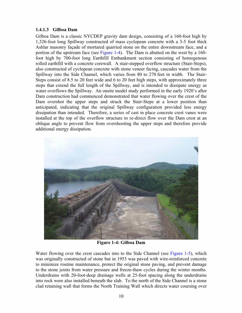
1.4.1.3 Gilboa Dam Gilboa Dam is a classic NYCDEP gravity dam design, consisting of a 160-foot high by 1,326-foot long Spillway constructed of mass cyclopean concrete with a 3-5 foot thick Ashlar masonry façade of mortared quarried stone on the entire downstream face, and a portion of the upstream face (see Figure 1-4). The Dam is abutted on the west by a 160-foot high by 700-foot long Earthfill Embankment section consisting of homogenous rolled earthfill with a concrete corewall. A stair-stepped overflow structure (Stair-Steps), also constructed of cyclopean concrete with stone veneer facing, cascades water from the Spillway into the Side Channel, which varies from 80 to 270 feet in width. The Stair-Steps consist of 8.5 to 20 feet wide and 6 to 20 feet high steps, with approximately three steps that extend the full length of the Spillway, and is intended to dissipate energy as water overflows the Spillway. An onsite model study performed in the early 1920’s after Dam construction had commenced demonstrated that water flowing over the crest of the Dam overshot the upper steps and struck the Stair-Steps at a lower position than anticipated, indicating that the original Spillway configuration provided less energy dissipation than intended. Therefore, a series of cast in place concrete crest vanes were installed at the top of the overflow structure to re-direct flow over the Dam crest at an oblique angle to prevent flow from overshooting the upper steps and therefore provide additional energy dissipation.
Figure 1-4: Gilboa Dam
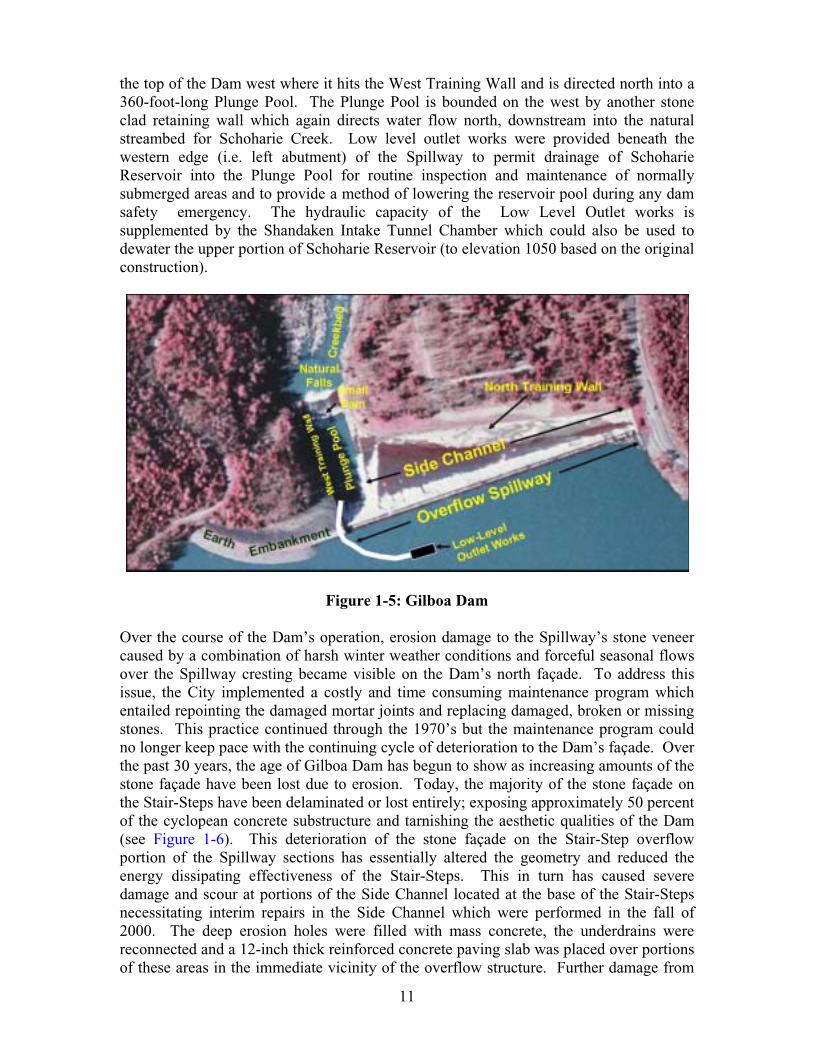
Water flowing over the crest cascades into to the Side Channel (see Figure 1-5), which was originally constructed of stone but in 1953 was paved with wire-reinforced concrete to minimize routine maintenance, protect the original stone paving, and prevent damage to the stone joints from water pressure and freeze-thaw cycles during the winter months. Underdrains with 20-foot-deep drainage wells at 25-foot spacing along the underdrains into rock were also installed beneath the slab. To the north of the Side Channel is a stone clad retaining wall that forms the North Training Wall which directs water coursing over
11
the top of the Dam west where it hits the West Training Wall and is directed north into a 360-foot-long Plunge Pool. The Plunge Pool is bounded on the west by another stone clad retaining wall which again directs water flow north, downstream into the natural streambed for Schoharie Creek. Low level outlet works were provided beneath the western edge (i.e. left abutment) of the Spillway to permit drainage of Schoharie Reservoir into the Plunge Pool for routine inspection and maintenance of normally submerged areas and to provide a method of lowering the reservoir pool during any dam safety emergency. The hydraulic capacity of the Low Level Outlet works is supplemented by the Shandaken Intake Tunnel Chamber which could also be used to dewater the upper portion of Schoharie Reservoir (to elevation 1050 based on the original construction).
Figure 1-5: Gilboa Dam
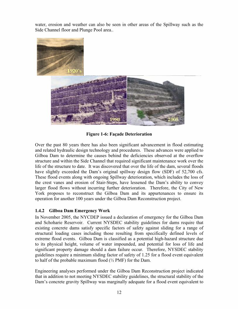
Over the course of the Dam’s operation, erosion damage to the Spillway’s stone veneer caused by a combination of harsh winter weather conditions and forceful seasonal flows over the Spillway cresting became visible on the Dam’s north façade. To address this issue, the City implemented a costly and time consuming maintenance program which entailed repointing the damaged mortar joints and replacing damaged, broken or missing stones. This practice continued through the 1970’s but the maintenance program could no longer keep pace with the continuing cycle of deterioration to the Dam’s façade. Over the past 30 years, the age of Gilboa Dam has begun to show as increasing amounts of the stone façade have been lost due to erosion. Today, the majority of the stone façade on the Stair-Steps have been delaminated or lost entirely; exposing approximately 50 percent of the cyclopean concrete substructure and tarnishing the aesthetic qualities of the Dam (see Figure 1-6). This deterioration of the stone façade on the Stair-Step overflow portion of the Spillway sections has essentially altered the geometry and reduced the energy dissipating effectiveness of the Stair-Steps. This in turn has caused severe damage and scour at portions of the Side Channel located at the base of the Stair-Steps necessitating interim repairs in the Side Channel which were performed in the fall of 2000. The deep erosion holes were filled with mass concrete, the underdrains were reconnected and a 12-inch thick reinforced concrete paving slab was placed over portions of these areas in the immediate vicinity of the overflow structure. Further damage from
12
water, erosion and weather can also be seen in other areas of the Spillway such as the Side Channel floor and Plunge Pool area..
Figure 1-6: Façade Deterioration
Over the past 80 years there has also been significant advancement in flood estimating and related hydraulic design technology and procedures. These advances were applied to Gilboa Dam to determine the causes behind the deficiencies observed at the overflow structure and within the Side Channel that required significant maintenance work over the life of the structure to date. It was discovered that over the life of the dam, several floods have slightly exceeded the Dam’s original spillway design flow (SDF) of 52,700 cfs. These flood events along with ongoing Spillway deterioration, which includes the loss of the crest vanes and erosion of Stair-Steps, have lessened the Dam’s ability to convey larger flood flows without incurring further deterioration. Therefore, the City of New York proposes to reconstruct the Gilboa Dam and its appurtenances to ensure its operation for another 100 years under the Gilboa Dam Reconstruction project.
1.4.2 Gilboa Dam Emergency Work In November 2005, the NYCDEP issued a declaration of emergency for the Gilboa Dam and Schoharie Reservoir. Current NYSDEC stability guidelines for dams require that existing concrete dams satisfy specific factors of safety against sliding for a range of structural loading cases including those resulting from specifically defined levels of extreme flood events. Gilboa Dam is classified as a potential high-hazard structure due to its physical height, volume of water impounded, and potential for loss of life and significant property damage should a dam failure occur. Therefore, NYSDEC stability guidelines require a minimum sliding factor of safety of 1.25 for a flood event equivalent to half of the probable maximum flood (½ PMF) for the Dam.
Engineering analyses performed under the Gilboa Dam Reconstruction project indicated that in addition to not meeting NYSDEC stability guidelines, the structural stability of the Dam’s concrete gravity Spillway was marginally adequate for a flood event equivalent to

13
the 70,800 cfs storm of record that occurred on January 19, 1996. This record flood event resulted in a maximum height of flow over the Spillway crest of 6.68 feet and is reported by the United States Geological Survey (USGS) to be equivalent to a 60-year flood event at the Dam. The engineering analyses indicated that failure of the Dam by sliding along weak planes within the immediate underlying foundation rock could occur for Spillway discharges exceeding eight (8) feet, which equates to slightly greater than a flood event with a 100-year return period (72,580 cfs). Therefore, NYCDEP immediately lowered the water surface elevation in the Schoharie Reservoir to reduce the risk of dam failure until emergency repairs could be completed.
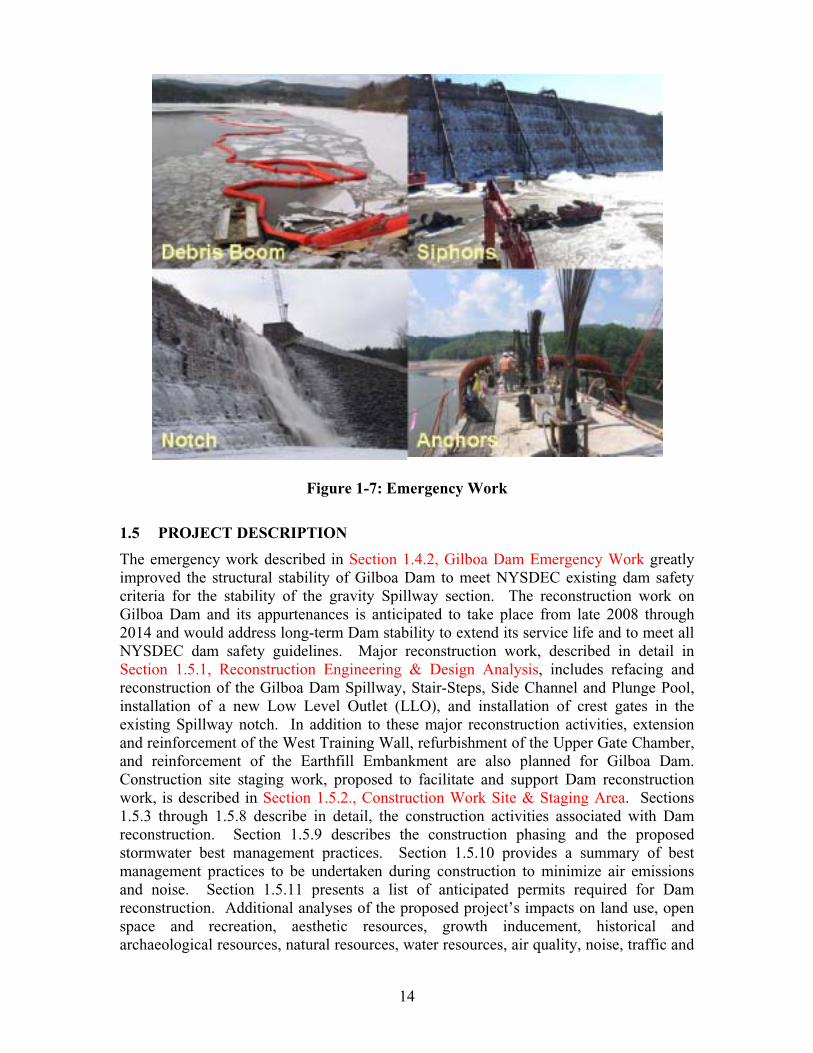
Interim remedial measures commenced in December 2005 to ensure that Gilboa Dam satisfied NYSDEC dam safety criteria for the stability of the gravity section in advance of the final reconstruction of the Dam, which is anticipated to begin in 2008. The primary emergency structural improvement to the Dam was the installation of post-tensioned anchors in the Spillway and its foundation, which improved the stability of the structure and ensured compliance with current dam safety stability guidelines for existing concrete dams. Prior to installing the post-tensioned anchors, NYCDEP implemented supplemental emergency remedial measures and temporary operational changes to improve the ability to regulate the reservoir water surface elevation, thus facilitating anchor installation. Measures taken directly at the Dam include the installation of a debris boom across the Reservoir to protect the work area; temporary siphons to help regulate reservoir levels; and a rectangular Spillway notch in the Spillway crest aligned with the Plunge Pool area to facilitate anchor installation (see Figure 1-7). Measures taken at other locations within the Catskill System to facilitate anchor installation and future work included activation of the waste diversion facilities at the Ashokan Reservoir and construction of a temporary flood-control berm, downstream of the waste diversion facility at the State University of New York (SUNY) New Paltz Ashokan Field Campus. These emergency remedial measures were completed in April 2006 and the debris barrier, siphons and notch have remained at the Dam since then. The installation of the post-tensioned anchors was completed in December 2006 which improved Gilboa Dam’s structural stability to meet NYSDEC stability guidelines and safety factors for existing dams.
14
Figure 1-7: Emergency Work
1.5 PROJECT DESCRIPTION
The emergency work described in Section 1.4.2, Gilboa Dam Emergency Work greatly improved the structural stability of Gilboa Dam to meet NYSDEC existing dam safety criteria for the stability of the gravity Spillway section. The reconstruction work on Gilboa Dam and its appurtenances is anticipated to take place from late 2008 through 2014 and would address long-term Dam stability to extend its service life and to meet all NYSDEC dam safety guidelines. Major reconstruction work, described in detail in Section 1.5.1, Reconstruction Engineering & Design Analysis, includes refacing and reconstruction of the Gilboa Dam Spillway, Stair-Steps, Side Channel and Plunge Pool, installation of a new Low Level Outlet (LLO), and installation of crest gates in the existing Spillway notch. In addition to these major reconstruction activities, extension and reinforcement of the West Training Wall, refurbishment of the Upper Gate Chamber, and reinforcement of the Earthfill Embankment are also planned for Gilboa Dam. Construction site staging work, proposed to facilitate and support Dam reconstruction work, is described in Section 1.5.2., Construction Work Site & Staging Area. Sections 1.5.3 through 1.5.8 describe in detail, the construction activities associated with Dam reconstruction. Section 1.5.9 describes the construction phasing and the proposed stormwater best management practices. Section 1.5.10 provides a summary of best management practices to be undertaken during construction to minimize air emissions and noise. Section 1.5.11 presents a list of anticipated permits required for Dam reconstruction. Additional analyses of the proposed project’s impacts on land use, open space and recreation, aesthetic resources, growth inducement, historical and archaeological resources, natural resources, water resources, air quality, noise, traffic and
15
transportation, energy and utilities, and public safety and health are described in full detail in Section 2 of this Environmental Assessment.
1.5.1 Reconstruction Engineering and Design Analysis As previously mentioned, the major reconstruction work on the Dam would consist of Dam refacing and reconstruction and installation of a LLO, as well as the installation of a crest gate system to assist in the provision of enhanced flood attenuation under a snowpack-based reservoir management program. A summary of the guidelines, analyses and resulting engineering designs for these phases of work are summarized in the following sections.
1.5.1.1 Dam Reconstruction Dam design and hydraulics have advanced significantly since Gilboa Dam was completed in 1927. Using modern laboratory technology and analysis techniques and a more complete data set of dam-related information, the present design team performed updated hydraulic and physical analyses to assess the condition and anticipated performance requirements of the existing Dam. Based on these analyses, engineering solutions were developed to improve hydraulic performance of the Dam, enhance the control section of the Spillway crest, and increase the Dam’s operation lifespan. The post-tensioned anchors installed as part of the emergency work addressed the Dam’s structural stability. Remaining work includes Spillway reconstruction, refacing the Stair-Step stone façade, reconstructing associated support structures such as the Side Channel, Plunge Pool, North Training Wall, and extending the West Training Wall.
1.5.1.1.1 GuidelinesNYSDEC has regulatory authority over the planned reconstruction improvements at Gilboa Dam. The primary regulation that governs the Dam reconstruction requirements is 6 NYCRR Part 673: Dam Safety Regulations. Based on the height and storage volume of the Dam at normal pool, Gilboa Dam is classified as “Large” under NYSDEC classification. Since the hypothetical failure of the Dam could cause loss of life and serious damage downstream, the Dam is considered a Class “C”, or “High” hazard structure under state regulations (as well as per criteria of the U.S. Army Corps of Engineers [USACOE] and the U.S. Bureau of Reclamation [USBR]). Based on these classifications, the NYCDEP and NYSDEC have collaboratively decided upon Dam reconstruction requirements including Dam stability and safety factor criteria, which have been largely addressed by the post-tensioned anchors installed as part of the emergency work (described in Section 1.4.2., Gilboa Dam Reconstruction Work). The remaining Dam reconstruction work focuses primarily on improving Dam performance and reducing maintenance so that Gilboa Dam can continue to meet these safety requirements and remain in use for another 100 years.
1.5.1.1.2 AnalysesUpdated Flow ParametersDam spillways are designed to provide sufficient capacity and structural integrity to safely pass an entire SDF6. As previously mentioned, NYSDEC stability guidelines for
6 The SDF denotes “spillway design flood” which represents the largest flood considered in the evaluation of the dam design.
16
existing dams require that the SDF equal the ½PMF. The original SDF of Gilboa Dam was 52,700 cubic feet per second (cfs) with a Spillway head of 6 feet. Although the hydraulic capacity of the Spillway at Gilboa Dam is adequate to convey flows greater than the original SDF, the energy-dissipating capabilities of the existing Stair-Step configuration are hydraulically and structurally inadequate to withstand the increased structural loading resulting from the increased Spillway head associated with greater flows, thus resulting in erosion in the Side Channel, North Training Wall and Plunge Pool.
Therefore, NYCDEP developed an updated hydrologic model based on current information and analysis techniques to analyze the hydrology of the Schoharie Watershed and to predict the flows anticipated at Gilboa Dam for a variety of flood events in order to determine an updated set of flow parameters for the reconstructed Dam. Historical and current watershed data from various sources were used as input into the model and calibrated using recorded precipitation and streamflow data gauges located within the Watershed. This data was then used to establish updated flow parameters through the watercourses of the basin for floods with return periods ranging from 2 to 500 years, and also to establish an updated ½PMF and PMF, with peak outflow of 311,400 cfs (which is approximately 6 times larger than the original SDF) and a maximum Spillway head of 17.4 prototype feet7.
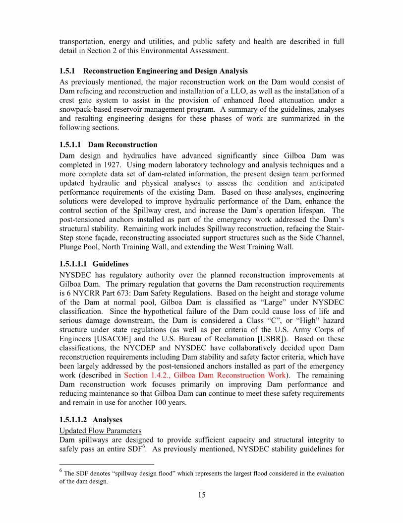
Physical Modeling and AnalysisA detailed physical model study of the existing and proposed Gilboa Dam configurations was performed at Utah State University to reconstruct or redesign the Dam to the highest Dam stability to accommodate the updated flow parameters determined in the aforementioned hydraulic analysis and to examine what hydraulic design changes to Gilboa Dam could be made to improve the safety of the Dam and also reduce future maintenance. The study consisted of the construction of a 1:20 scale model of the existing Spillway and various configurations of alternative stair-stepped Spillways to determine the optimal Spillway structure under the updated flow parameters. In addition, a 1:40 scale model of the entire Dam structure was constructed to determine the effect of the updated flow parameters, optimize the Spillway structure design determined in the 1:20 model study, and to identify other improvements to the Dam’s hydraulic structures.
7 Prototype feet as determined by the model dam described in the following section.

17
Figure 1-8: 1:20 Model
The 1:20 scale sectional three-dimensional model was first assembled to reproduce the existing stepped profile of Gilboa Dam (Figure 1-8) and to study the original crest and Spillway design under the maximum overflow of the original design criteria. The physical modeling results of this reproduction were consistent with the erosion and damage to the Dam which is visible today, thus validating the model for use in the development of a new Spillway configuration. The existing Stair-Step profile was also tested using the updated flow parameters, which crested more than 15 feet above the existing Dam with very little water striking the Dam’s horizontal steps. This confirmed that the original Dam design was inadequate to control an overflow of this magnitude.
The purpose of a stair-stepped Spillway is to reduce or eliminate the need for energy dissipation of the overflow and energy dissipation structures downstream of the Spillway. In addition, an effective Spillway should reduce the impact to and erosion of channel inverts and banks downstream of the Spillway. The stair-stepped Spillway configuration is intended to create energy dissipation through the mechanics of aeration, flow separation of vortex/roller action at the junction of the steps, and the impact and momentum exchange of the flow on the steps. Keeping these design goals in mind, 30 modifications to the original crest and Spillway were studied, including (1) modified design configurations with a mitered crest, (2) modified designs with ogee crest shapes (S-shaped), and (3) the application of the different crest designs with and without crest vanes, using the updated flow parameters to determine the optimal Spillway step configuration (discussed in greater detail in the Section 1.5.1.1.3, Design).
18
Figure 1-9: 1:40 Model
Using the updated flow parameters and optimized Spillway step configuration, a 1:40 scale physical model (Figure 1-9) was built to assess the hydraulic capacity and structural stability of the concrete Spillway as well as the structural stability of the other critical Dam structures including the adjoining Earth Embankment, West Training Wall, and Overflow Structure steps. In addition, channel velocities for flood events with 100-year, 500-year, ½ PMF return periods were used to evaluate the performance of potential energy dissipation modifications to the concrete Side Channel and Plunge Pool. The physical model was also updated during the emergency work to include the 5.5-foot deep notch to provide additional information on how this modification would affect the overflow. The 1:40 model results demonstrated that the notch, if present in the crest, would have no effect on the Spillway’s ability to pass the flow parameters.
Based on information obtained from the 1:40 physical model, several modifications to the Dam and surrounding structures as described in Section 1.5.1.1.3, Design have been proposed.
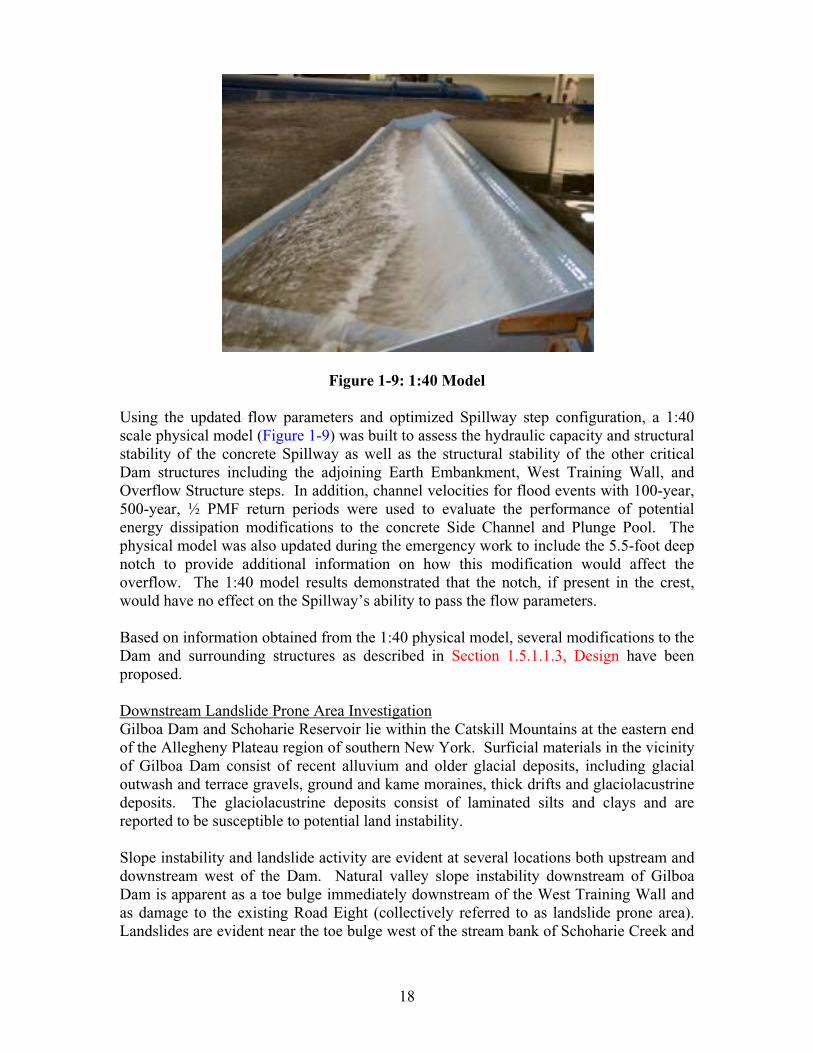
Downstream Landslide Prone Area InvestigationGilboa Dam and Schoharie Reservoir lie within the Catskill Mountains at the eastern end of the Allegheny Plateau region of southern New York. Surficial materials in the vicinity of Gilboa Dam consist of recent alluvium and older glacial deposits, including glacial outwash and terrace gravels, ground and kame moraines, thick drifts and glaciolacustrine deposits. The glaciolacustrine deposits consist of laminated silts and clays and are reported to be susceptible to potential land instability.
Slope instability and landslide activity are evident at several locations both upstream and downstream west of the Dam. Natural valley slope instability downstream of Gilboa Dam is apparent as a toe bulge immediately downstream of the West Training Wall and as damage to the existing Road Eight (collectively referred to as landslide prone area). Landslides are evident near the toe bulge west of the stream bank of Schoharie Creek and
19
immediately adjacent to the Plunge Pool where earth material has cascaded down the valley slope into the creek bed (see Figure 1-10). Based on studies by NYCDEP, New York Power Authority, and others, the slope movement within the landslide prone area occurs as both shallow and deep-seated failures as well as surficial sloughing. A significant portion of this slope is comprised of Schoharie soils, which are described as unstable with respect to slope stability. These soils generally have low shear strength, are susceptible to shirking and swelling, and experience seasonally high water tables. Additional factors contributing to the landslide activity include continual scour of the toe slope during periods of high stream flow within Schoharie Creek, soil creep caused by freezing and thawing of unconsolidated surface material, steep slopes, vegetation types, and saturation of the overburden due to precipitation and poor surface drainage. NYCDEP has initiated an ongoing geotechnical subsurface investigation consisting of field reconnaissance and a boring program. The geotechnical investigation includes the installation of inclinometers to measure movement within the slope to define the subsurface profile, and laboratory testing to measure the properties of the soils sampled from the borings. Based on the subsurface and laboratory investigations, detailed geologic profiles and cross-sections of the Landslide Prone Area are being developed and material properties are being defined for use in final slope stability evaluations. The first portion of the investigation has focused on slope stability issues directly downstream of Gilboa Dam and has been used in the design of the extension of the West Training Wall (discussed in Section 1.5.5.2, West Training Wall), which is included in the proposed Gilboa Dam Reconstruction project. The second portion of the investigation concentrates on the remaining portion of the Landslide Prone Area further downstream along Road 8 and is ongoing. Depending on the results of this investigation, NYCDEP would determine if further landslide stabilization is required and analyze landslide mitigation measures such as regrading and revegetating the slope to reduce water infiltration, providing erosion resistance, and allowing for periodic slope inspection. Any geo-structural alternative would have an ecological impact on the area and require a separate environmental review before initiation.

Ú ·¹«®» ïóïð
Ô¿²¼´·¼» Ю±²» ß®»¿
ß Ö±·²¬ Ê»²¬«®»
ÝßÌî ï ï
Û²¹·²»»®·²¹ Ü»·¹² Í»®ª·½» ¿²¼ Ü»·¹² Ü«®·²¹ ݱ²¬®«½¬·±²º±® ¬¸» λ½±²¬®«½¬·±² ±º Ý¿¬µ·´´ É¿¬»®¸»¼ Ü¿³ ¿²¼ ß±½·¿¬»¼ Ú¿½·´·¬·»
Ù×ÔÞÑßÜßÓ
̱» Þ«´¹»
Ô¿²¼´·¼»Ð®±²» ß®»¿
21
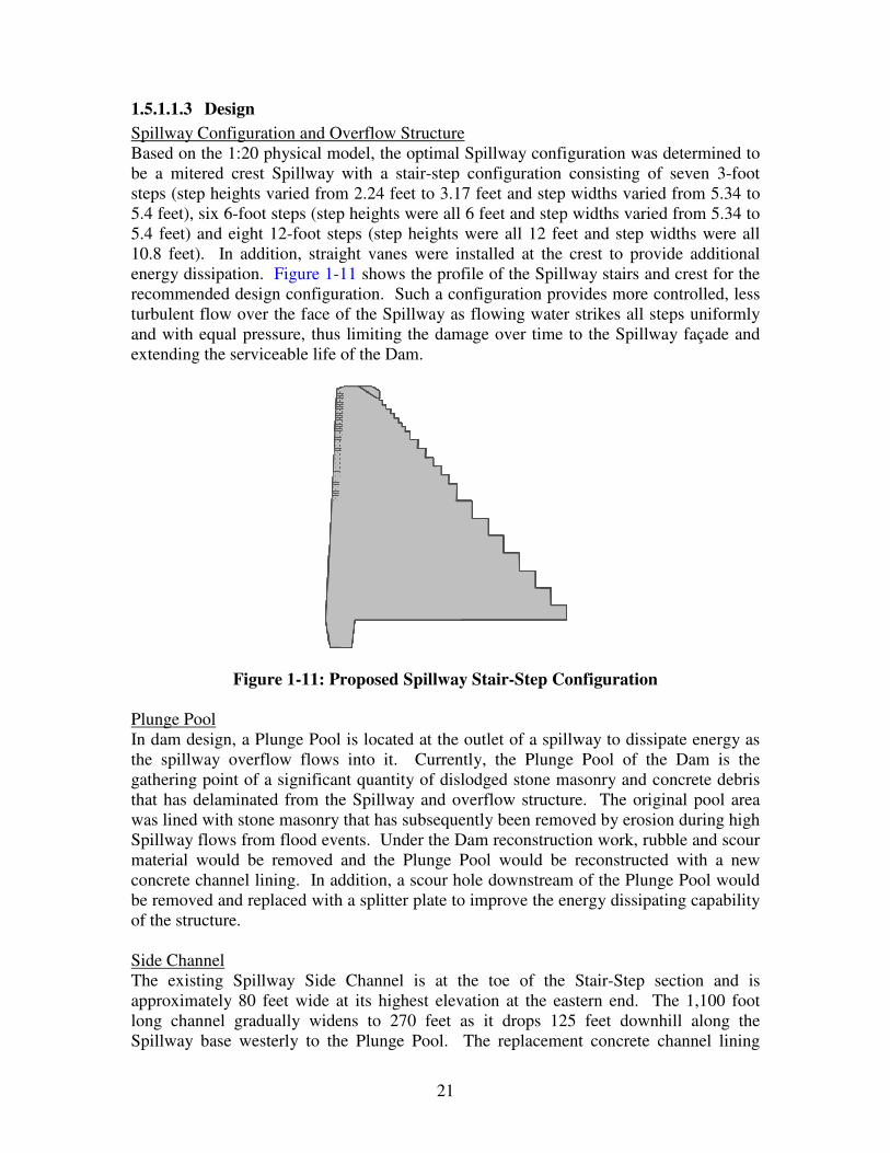
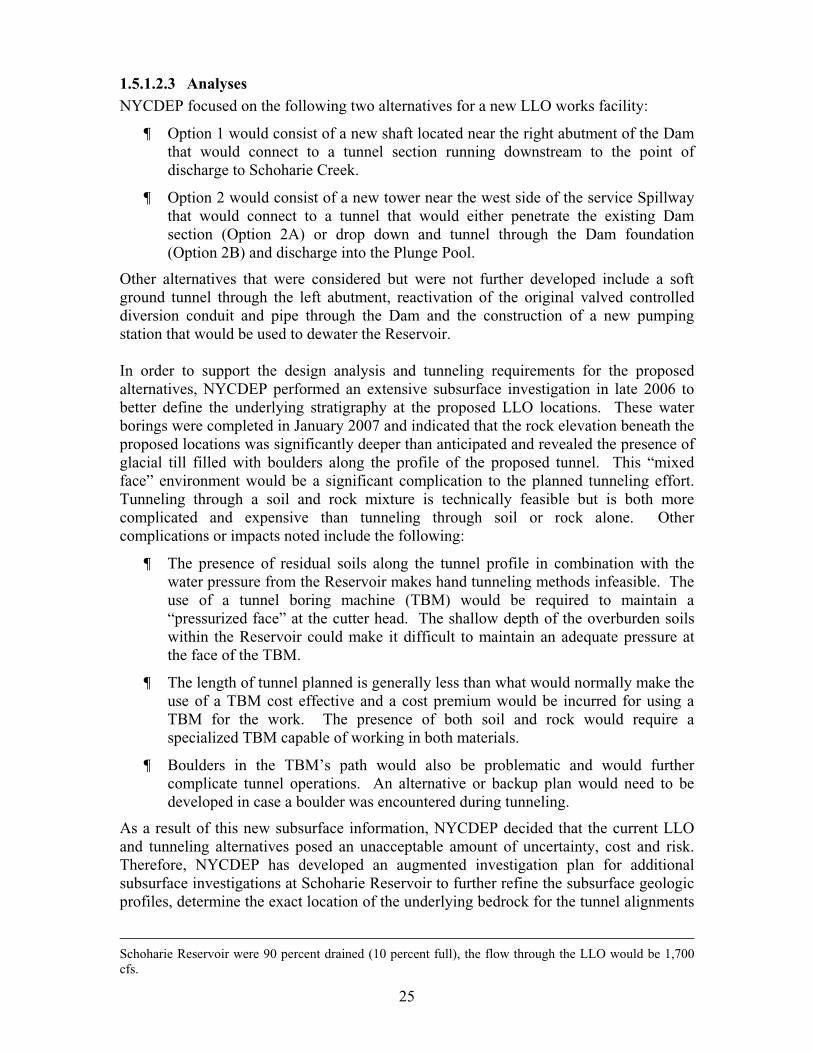
1.5.1.1.3 Design Spillway Configuration and Overflow Structure Based on the 1:20 physical model, the optimal Spillway configuration was determined to be a mitered crest Spillway with a stair-step configuration consisting of seven 3-foot steps (step heights varied from 2.24 feet to 3.17 feet and step widths varied from 5.34 to 5.4 feet), six 6-foot steps (step heights were all 6 feet and step widths varied from 5.34 to 5.4 feet) and eight 12-foot steps (step heights were all 12 feet and step widths were all 10.8 feet). In addition, straight vanes were installed at the crest to provide additional energy dissipation. Figure 1-11 shows the profile of the Spillway stairs and crest for the recommended design configuration. Such a configuration provides more controlled, less turbulent flow over the face of the Spillway as flowing water strikes all steps uniformly and with equal pressure, thus limiting the damage over time to the Spillway façade and extending the serviceable life of the Dam.
Figure 1-11: Proposed Spillway Stair-Step Configuration Plunge Pool In dam design, a Plunge Pool is located at the outlet of a spillway to dissipate energy as the spillway overflow flows into it. Currently, the Plunge Pool of the Dam is the gathering point of a significant quantity of dislodged stone masonry and concrete debris that has delaminated from the Spillway and overflow structure. The original pool area was lined with stone masonry that has subsequently been removed by erosion during high Spillway flows from flood events. Under the Dam reconstruction work, rubble and scour material would be removed and the Plunge Pool would be reconstructed with a new concrete channel lining. In addition, a scour hole downstream of the Plunge Pool would be removed and replaced with a splitter plate to improve the energy dissipating capability of the structure. Side Channel The existing Spillway Side Channel is at the toe of the Stair-Step section and is approximately 80 feet wide at its highest elevation at the eastern end. The 1,100 foot long channel gradually widens to 270 feet as it drops 125 feet downhill along the Spillway base westerly to the Plunge Pool. The replacement concrete channel lining
22
poured in the 1950’s is currently in varying degrees of deterioration throughout its areal extent and is structurally inadequate to withstand the updated flow parameters. Under the Dam reconstruction work, the concrete material and bluestone in the Side Channel would be removed and a new concrete channel lining would be installed which includes a recessed channel that runs along the North Training Wall to improve hydraulics. Notch The 1:40 model results demonstrated that the 5.5-foot notch installed in the crest as part of the emergency work (as described in Section 1.4.2, Gilboa Dam Emergency Work) has no effect on the Spillway’s ability to pass the updated flow parameters and peak outflow. Other Modifications Additional modifications identified from the physical model study include extension of the adjacent West Training Wall and the construction of an armored earthen berm north of the North Training Wall embankment to provide additional control over the flow of water as it moves downstream.
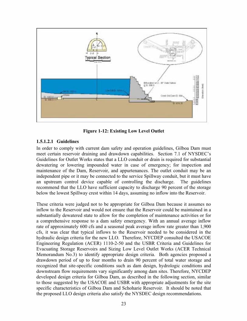
1.5.1.2 Low Level Outlet (LLO) As discussed in Section 1.4.1.3., Gilboa Dam, the original outlet for the low level outlet works of the Schoharie Reservoir is situated at the upstream end of the Plunge Pool beneath the western edge (i.e., left abutment) of the Spillway (refer to Figures 1-5 and 1-12). This structure was originally constructed to provide drainage of the Reservoir during routine inspection and maintenance of normally submerged areas or for emergency drawdown purposes when used in combination with the existing Shandaken Tunnel Intake structure. Since the 1960’s, it has not been operated due to the accumulation of sediment over the inlet pipe in the Reservoir. In addition, the existing valving located in the Gate Control Chamber just west of the Spillway is in questionable condition. Therefore, new outlet works have been included in the proposed Gilboa Dam Reconstruction project to facilitate Reservoir drawdown as needed to suitably respond to Dam safety emergencies, and to allow for periodic maintenance of the Dam. As part of this proposed reconstruction of the LLO, NYCDEP is considering the installation of a warning system to notify downstream communities should an emergency release be necessary. A secondary potential use of the new LLO would be as a component of snowpack-based reservoir management (further discussed in Section 1.5.1.3., Snowpack-Based Reservoir Management/Spillway Notch).
23
Figure 1-12: Existing Low Level Outlet
1.5.1.2.1 GuidelinesIn order to comply with current dam safety and operation guidelines, Gilboa Dam must meet certain reservoir draining and drawdown capabilities. Section 7.1 of NYSDEC’s Guidelines for Outlet Works states that a LLO conduit or drain is required for substantial dewatering or lowering impounded water in case of emergency; for inspection and maintenance of the Dam, Reservoir, and appurtenances. The outlet conduit may be an independent pipe or it may be connected to the service Spillway conduit, but it must have an upstream control device capable of controlling the discharge. The guidelines recommend that the LLO have sufficient capacity to discharge 90 percent of the storage below the lowest Spillway crest within 14 days, assuming no inflow into the Reservoir.
These criteria were judged not to be appropriate for Gilboa Dam because it assumes no inflow to the Reservoir and would not ensure that the Reservoir could be maintained in a substantially dewatered state to allow for the completion of maintenance activities or for a comprehensive response to a dam safety emergency. With an annual average inflow rate of approximately 600 cfs and a seasonal peak average inflow rate greater than 1,900 cfs, it was clear that typical inflows to the Reservoir needed to be considered in the hydraulic design criteria for the new LLO. Therefore, NYCDEP consulted the USACOE Engineering Regulation (ACER) 1110-2-50 and the USBR Criteria and Guidelines for Evacuating Storage Reservoirs and Sizing Low Level Outlet Works (ACER Technical Memorandum No.3) to identify appropriate design criteria. Both agencies proposed a drawdown period of up to four months to drain 90 percent of total water storage and recognized that site-specific conditions such as dam design, hydrologic conditions and downstream flow requirements vary significantly among dam sites. Therefore, NYCDEP developed design criteria for Gilboa Dam, as described in the following section, similar to those suggested by the USACOE and USBR with appropriate adjustments for the site specific characteristics of Gilboa Dam and Schoharie Reservoir. It should be noted that the proposed LLO design criteria also satisfy the NYSDEC design recommendations.

24
1.5.1.2.2 Design Criteria The LLO design criteria are based on NYSDEC guidelines with specific guidance provided by federal agencies with institutional control over new and existing dams, such as the USACOE, USBR, and the Federal Energy Regulatory Commission (FERC) as well as site-specific factors. The primary design goals are that the drawdown facilities at Gilboa Dam should be capable of (a) quickly lowering the Reservoir water level in response to an unanticipated dam safety emergency and (b) maintaining the Reservoir in a substantially dewatered state during typical inflow conditions that could occur at various times during a given year. The operational and design criteria are as follows:
¶ Capacity to evacuate 90 percent of the Reservoir storage volume (lower the Reservoir water elevation to 1052 feet) under average inflow conditions (600 cfs)), or elevation 1052 feet, in less than 4 months8.
¶ Capacity to maintain the Reservoir in a substantially dewatered state under average inflow conditions; the LLO should be capable of maintaining the Reservoir at a water level at or below elevation 1052 feet, which represents ten percent of the storage volume.
¶ An invert elevation for the lowest drain in the range of elevation 980 to 1000 feet. The Reservoir would be fully drained at an elevation of about 990. Minor amounts of water remaining in the Reservoir are not significant from a dam safety perspective.
¶ No reliance on use of the Shandaken Tunnel Intake to meet above criteria.9
Shandaken Tunnel Intake would only be used if higher rates of Reservoir dewatering are deemed necessary due to unusual circumstances.
¶ Maximum daily drawdown rates should be in the range of 1 to 2 feet per day, unless higher rates are deemed to be required by extreme emergencies. Although the LLO capacity will be greater than the maximum drawdown rates under certain conditions, higher evacuation rates carry an increased risk of localized slope instability problems at the Dam and around the Reservoir perimeter. The risk of localized problems increases in proportion to the magnitude of the total change in Reservoir water level.
Based on this criteria and available historical meteorological and hydrological inflow data at Schoharie Reservoir, a maximum capacity of approximately 2,500 cfs under normal pool elevation was selected for the LLO.10
8 US Army Corps of Engineers’ Engineering Regulation 1110-2-50 suggests that that, within a period of four months, a reservoir should be drawn down to a level where the remaining storage in the reservoir is ten percent of the storage at normal pool which is typically the spillway crest elevation. 9 Historically, Shandaken Tunnel Intake has been considered to be an integral component for emergency dewatering of Schoharie Reservoir. While this option continues to be available to NYCDEP subject to the regulatory constraints found elsewhere in existing NYSDEC rules (NYCRR Part 670: Reservoir Release Regulations: Schoharie Reservoir, Shandaken Tunnel-Esopus Creek, Section 3 and SPDES Permit) it is recommended that the design criteria for any new drawdown facilities not be dependent upon use of the existing intake.10 It is important to note that this maximum flow would only occur when Schoharie Reservoir is full and the LLO is fully opened. Flow through the LLO would decrease over the course of the draining process as the Reservoir level drops and reduces the hydraulic head acting at the Outlet’s intake. For example, if
25
1.5.1.2.3 AnalysesNYCDEP focused on the following two alternatives for a new LLO works facility:
¶ Option 1 would consist of a new shaft located near the right abutment of the Dam that would connect to a tunnel section running downstream to the point of discharge to Schoharie Creek.
¶ Option 2 would consist of a new tower near the west side of the service Spillway that would connect to a tunnel that would either penetrate the existing Dam section (Option 2A) or drop down and tunnel through the Dam foundation (Option 2B) and discharge into the Plunge Pool.
Other alternatives that were considered but were not further developed include a soft ground tunnel through the left abutment, reactivation of the original valved controlled diversion conduit and pipe through the Dam and the construction of a new pumping station that would be used to dewater the Reservoir.
In order to support the design analysis and tunneling requirements for the proposed alternatives, NYCDEP performed an extensive subsurface investigation in late 2006 to better define the underlying stratigraphy at the proposed LLO locations. These water borings were completed in January 2007 and indicated that the rock elevation beneath the proposed locations was significantly deeper than anticipated and revealed the presence of glacial till filled with boulders along the profile of the proposed tunnel. This “mixed face” environment would be a significant complication to the planned tunneling effort. Tunneling through a soil and rock mixture is technically feasible but is both more complicated and expensive than tunneling through soil or rock alone. Other complications or impacts noted include the following:
¶ The presence of residual soils along the tunnel profile in combination with the water pressure from the Reservoir makes hand tunneling methods infeasible. The use of a tunnel boring machine (TBM) would be required to maintain a “pressurized face” at the cutter head. The shallow depth of the overburden soils within the Reservoir could make it difficult to maintain an adequate pressure at the face of the TBM.
¶ The length of tunnel planned is generally less than what would normally make the use of a TBM cost effective and a cost premium would be incurred for using a TBM for the work. The presence of both soil and rock would require a specialized TBM capable of working in both materials.
¶ Boulders in the TBM’s path would also be problematic and would further complicate tunnel operations. An alternative or backup plan would need to be developed in case a boulder was encountered during tunneling.
As a result of this new subsurface information, NYCDEP decided that the current LLO and tunneling alternatives posed an unacceptable amount of uncertainty, cost and risk. Therefore, NYCDEP has developed an augmented investigation plan for additional subsurface investigations at Schoharie Reservoir to further refine the subsurface geologic profiles, determine the exact location of the underlying bedrock for the tunnel alignments
Schoharie Reservoir were 90 percent drained (10 percent full), the flow through the LLO would be 1,700 cfs.
26
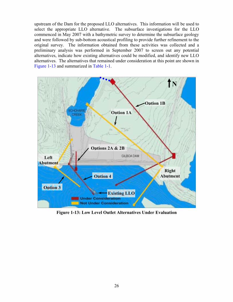
upstream of the Dam for the proposed LLO alternatives. This information will be used to select the appropriate LLO alternative. The subsurface investigations for the LLO commenced in May 2007 with a bathymetric survey to determine the subsurface geology and were followed by sub-bottom acoustical profiling to provide further refinement to the original survey. The information obtained from these activities was collected and a preliminary analysis was performed in September 2007 to screen out any potential alternatives, indicate how existing alternatives could be modified, and identify new LLO alternatives. The alternatives that remained under consideration at this point are shown in Figure 1-13 and summarized in Table 1-1.
Figure 1-13: Low Level Outlet Alternatives Under Evaluation
Option 1B
Option 1A
Options 2A & 2B
Option 4
Option 3Existing LLO
RightAbutment
LeftAbutment
N
27
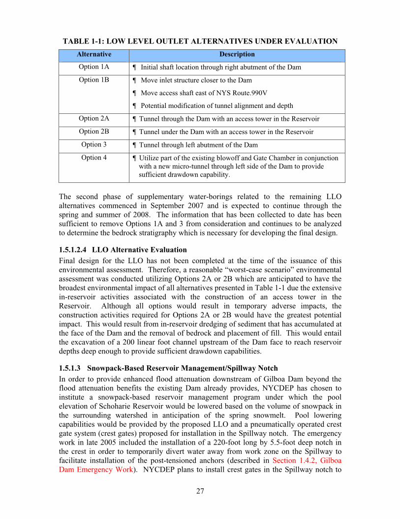
TABLE 1-1: LOW LEVEL OUTLET ALTERNATIVES UNDER EVALUATION
Alternative Description
Option 1A ¶ Initial shaft location through right abutment of the Dam
Option 1B ¶ Move inlet structure closer to the Dam
¶ Move access shaft east of NYS Route.990V
¶ Potential modification of tunnel alignment and depth
Option 2A ¶ Tunnel through the Dam with an access tower in the Reservoir
Option 2B ¶ Tunnel under the Dam with an access tower in the Reservoir
Option 3 ¶ Tunnel through left abutment of the Dam
Option 4 ¶ Utilize part of the existing blowoff and Gate Chamber in conjunction with a new micro-tunnel through left side of the Dam to provide sufficient drawdown capability.
The second phase of supplementary water-borings related to the remaining LLO alternatives commenced in September 2007 and is expected to continue through the spring and summer of 2008. The information that has been collected to date has been sufficient to remove Options 1A and 3 from consideration and continues to be analyzed to determine the bedrock stratigraphy which is necessary for developing the final design.
1.5.1.2.4 LLO Alternative Evaluation Final design for the LLO has not been completed at the time of the issuance of this environmental assessment. Therefore, a reasonable “worst-case scenario” environmental assessment was conducted utilizing Options 2A or 2B which are anticipated to have the broadest environmental impact of all alternatives presented in Table 1-1 due the extensive in-reservoir activities associated with the construction of an access tower in the Reservoir. Although all options would result in temporary adverse impacts, the construction activities required for Options 2A or 2B would have the greatest potential impact. This would result from in-reservoir dredging of sediment that has accumulated at the face of the Dam and the removal of bedrock and placement of fill. This would entail the excavation of a 200 linear foot channel upstream of the Dam face to reach reservoir depths deep enough to provide sufficient drawdown capabilities.
1.5.1.3 Snowpack-Based Reservoir Management/Spillway Notch In order to provide enhanced flood attenuation downstream of Gilboa Dam beyond the flood attenuation benefits the existing Dam already provides, NYCDEP has chosen to institute a snowpack-based reservoir management program under which the pool elevation of Schoharie Reservoir would be lowered based on the volume of snowpack in the surrounding watershed in anticipation of the spring snowmelt. Pool lowering capabilities would be provided by the proposed LLO and a pneumatically operated crest gate system (crest gates) proposed for installation in the Spillway notch. The emergency work in late 2005 included the installation of a 220-foot long by 5.5-foot deep notch in the crest in order to temporarily divert water away from work zone on the Spillway to facilitate installation of the post-tensioned anchors (described in Section 1.4.2, Gilboa Dam Emergency Work). NYCDEP plans to install crest gates in the Spillway notch to

28
restore the Reservoir’s original storage capacity and provide maximum capability for performing seasonal cold water releases through the Shandaken Tunnel while also continuing to provide an enhanced flood attenuation benefit to residents and businesses located downstream of the Dam. The installation of the crest gates would involve a slight modification to the Spillway crest so that it could be fitted with moveable crest gates that can facilitate a lower pool as part of a proposed snowpack-based reservoir management program (described further in the following section).
1.5.1.3.1 Snowpack-Based Reservoir Management Basis NYCDEP has decided to institute a snowpack-based reservoir management program, similar to the program formerly employed at other New York City Water Supply reservoirs located in the Delaware Watershed, to provide enhanced flood attenuation downstream. Under this program, Schoharie Reservoir would be sustained below full capacity during the winter months when sufficient snowpack is present in its watershed such that associated runoff produced by spring snowmelt could refill the Reservoir to full storage capacity. The capture of inflows associated with spring storm events and snowmelt runoff in the Reservoir would provide additional attenuation in downstream sections. The temporary reservoir level strived for during the snowpack-based reservoir management period would be regularly adjusted based on snow water equivalent (SWE) estimates of the watershed’s regularly monitored snowpack. As the name implies, SWE is the water depth equivalent of a given depth of snow and is dependent upon such factors as the snowpack’s water content and density.
1.5.1.3.2 AnalysesAs part of the ongoing design work associated with the reconstruction of the Dam, NYCDEP analyzed potential modifications to enhance flood attenuation in communities downstream of the Dam. It is important to consider that the primary purpose of the Dam and the Reservoir is to provide public water supply and therefore its ability to serve other secondary purposes is limited. Although Gilboa Dam already provides some level of flood attenuation, its ability to afford significant flood attenuation is limited since the Reservoir’s watershed represents only 34 percent of the total drainage area of Schoharie Creek downstream of the Dam.
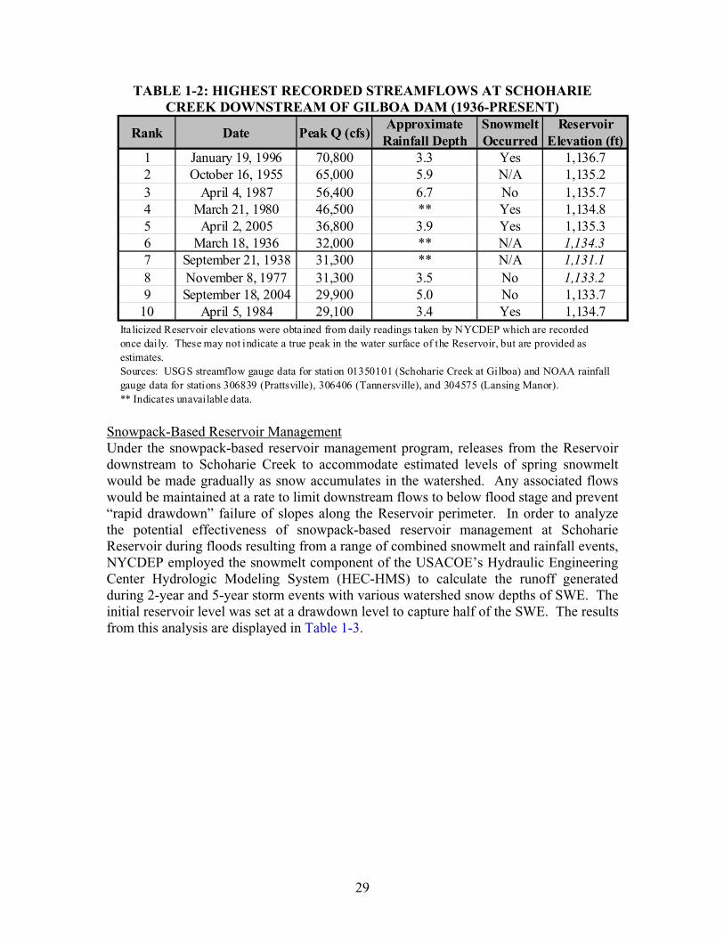
Historical Gilboa Streamflow AnalysisIn order to determine whether or not consideration of a snowpack-based reservoir management program was appropriate at Schoharie Reservoir to provide flood attenuation, a hydrologic and meteorological analysis was performed to ascertain the nature and seasonality of significant historic flows that have occurred in the area. Table 1-2 is a list of the largest recorded storm events measured at Schoharie Creek directly downstream of the Dam by the USGS streamflow gauge at Gilboa (No. 01350101) since 1936. Where data is available, approximate depths of the rainfall corresponding to each storm and an indication of whether or not snow was on the ground at the time of each storm are included.
The information presented in Table 1-2 demonstrates that six of the top ten record storm events at Schoharie Creek downstream of the Reservoir occurred during the Reservoir refill period. In addition, record storm events during this time are often the result of a rainfall-snowmelt combination, including the highest recorded storm runoff on January 19, 1996.
29
TABLE 1-2: HIGHEST RECORDED STREAMFLOWS AT SCHOHARIE CREEK DOWNSTREAM OF GILBOA DAM (1936-PRESENT)
Rank Date Peak Q (cfs)Approximate
Rainfall Depth Snowmelt Occurred
Reservoir Elevation (ft)
1 January 19, 1996 70,800 3.3 Yes 1,136.72 October 16, 1955 65,000 5.9 N/A 1,135.23 April 4, 1987 56,400 6.7 No 1,135.74 March 21, 1980 46,500 ** Yes 1,134.85 April 2, 2005 36,800 3.9 Yes 1,135.36 March 18, 1936 32,000 ** N/A 1,134.37 September 21, 1938 31,300 ** N/A 1,131.18 November 8, 1977 31,300 3.5 No 1,133.29 September 18, 2004 29,900 5.0 No 1,133.7
10 April 5, 1984 29,100 3.4 Yes 1,134.7
gauge data for stations 306839 (Prattsville), 306406 (Tannersville), and 304575 (Lansing Manor).** Indicates unavailable data.
Ita licized Reservoir elevations were obta ined from daily readings taken by NYCDEP which are recordedonce daily. These may not indicate a true peak in the water surface of the Reservoir, but are provided asestimates.Sources: USGS streamflow gauge data for station 01350101 (Schoharie Creek at Gilboa) and NOAA rainfall
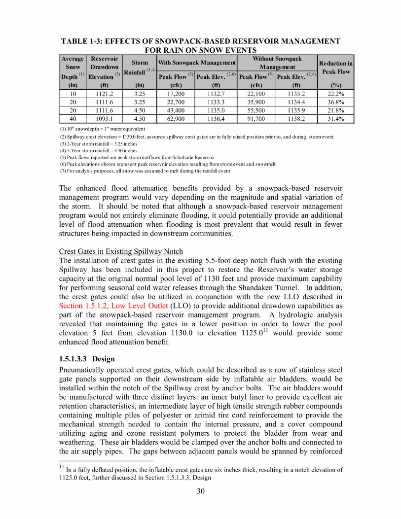
Snowpack-Based Reservoir ManagementUnder the snowpack-based reservoir management program, releases from the Reservoir downstream to Schoharie Creek to accommodate estimated levels of spring snowmelt would be made gradually as snow accumulates in the watershed. Any associated flows would be maintained at a rate to limit downstream flows to below flood stage and prevent “rapid drawdown” failure of slopes along the Reservoir perimeter. In order to analyze the potential effectiveness of snowpack-based reservoir management at Schoharie Reservoir during floods resulting from a range of combined snowmelt and rainfall events, NYCDEP employed the snowmelt component of the USACOE’s Hydraulic Engineering Center Hydrologic Modeling System (HEC-HMS) to calculate the runoff generated during 2-year and 5-year storm events with various watershed snow depths of SWE. The initial reservoir level was set at a drawdown level to capture half of the SWE. The results from this analysis are displayed in Table 1-3.
30
TABLE 1-3: EFFECTS OF SNOWPACK-BASED RESERVOIR MANAGEMENT FOR RAIN ON SNOW EVENTS
Peak Flow (5) Peak Elev. (2,6) Peak Flow (5) Peak Elev. (2,6)
(in) (ft) (in) (cfs) (ft) (cfs) (ft) (%)10 1121.2 3.25 17,200 1132.7 22,100 1133.2 22.2%20 1111.6 3.25 22,700 1133.3 35,900 1134.4 36.8%20 1111.6 4.50 43,400 1135.0 55,500 1135.9 21.8%40 1093.1 4.50 62,900 1136.4 91,700 1138.2 31.4%
(1) 10" snowdepth = 1" water equivalent
(2) Spillway crest elevation = 1130.0 feet, assumes spillway crest gates are in fully raised position prior to, and during, storm event(3) 2-Year storm rainfall = 3.25 inches(4) 5-Year storm rainfall = 4.50 inches(5) Peak flows reported are peak storm outflows from Schoharie Reservoir(6) Peak elevations shown represent peak reservoir elevation resulting from storm event and snowmelt(7) For analysis purposes, all snow was assumed to melt during the rainfall event
Reduction in Peak Flow
Average Snow
Depth (1)
Reservoir Drawdown
Elevation (2)
Storm
Rainfall (3,4)
With Snowpack ManagementWithout Snowpack
Management
The enhanced flood attenuation benefits provided by a snowpack-based reservoir management program would vary depending on the magnitude and spatial variation of the storm. It should be noted that although a snowpack-based reservoir management program would not entirely eliminate flooding, it could potentially provide an additional level of flood attenuation when flooding is most prevalent that would result in fewer structures being impacted in downstream communities.
Crest Gates in Existing Spillway NotchThe installation of crest gates in the existing 5.5-foot deep notch flush with the existing Spillway has been included in this project to restore the Reservoir’s water storage capacity at the original normal pool level of 1130 feet and provide maximum capability for performing seasonal cold water releases through the Shandaken Tunnel. In addition, the crest gates could also be utilized in conjunction with the new LLO described in Section 1.5.1.2, Low Level Outlet (LLO) to provide additional drawdown capabilities as part of the snowpack-based reservoir management program. A hydrologic analysis revealed that maintaining the gates in a lower position in order to lower the pool elevation 5 feet from elevation 1130.0 to elevation 1125.011 would provide some enhanced flood attenuation benefit.
1.5.1.3.3 DesignPneumatically operated crest gates, which could be described as a row of stainless steel gate panels supported on their downstream side by inflatable air bladders, would be installed within the notch of the Spillway crest by anchor bolts. The air bladders would be manufactured with three distinct layers: an inner butyl liner to provide excellent air retention characteristics, an intermediate layer of high tensile strength rubber compounds containing multiple piles of polyester or arimid tire cord reinforcement to provide the mechanical strength needed to contain the internal pressure, and a cover compound utilizing aging and ozone resistant polymers to protect the bladder from wear and weathering. These air bladders would be clamped over the anchor bolts and connected to the air supply pipes. The gaps between adjacent panels would be spanned by reinforced
11 In a fully deflated position, the inflatable crest gates are six inches thick, resulting in a notch elevation of 1125.0 feet, further discussed in Section 1.5.1.3.3, Design
31
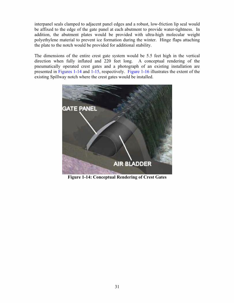
interpanel seals clamped to adjacent panel edges and a robust, low-friction lip seal would be affixed to the edge of the gate panel at each abutment to provide water-tightness. In addition, the abutment plates would be provided with ultra-high molecular weight polyethylene material to prevent ice formation during the winter. Hinge flaps attaching the plate to the notch would be provided for additional stability.
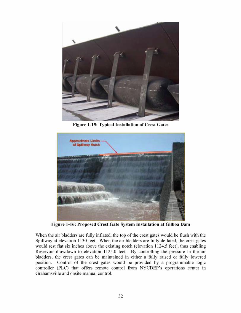
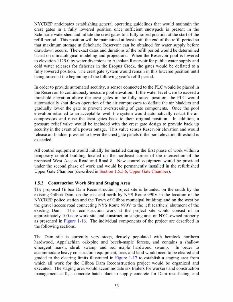
The dimensions of the entire crest gate system would be 5.5 feet high in the vertical direction when fully inflated and 220 feet long. A conceptual rendering of the pneumatically operated crest gates and a photograph of an existing installation are presented in Figures 1-14 and 1-15, respectively. Figure 1-16 illustrates the extent of the existing Spillway notch where the crest gates would be installed.
Figure 1-14: Conceptual Rendering of Crest Gates
32
Figure 1-15: Typical Installation of Crest Gates
Figure 1-16: Proposed Crest Gate System Installation at Gilboa Dam
When the air bladders are fully inflated, the top of the crest gates would be flush with the Spillway at elevation 1130 feet. When the air bladders are fully deflated, the crest gates would rest flat six inches above the existing notch (elevation 1124.5 feet), thus enabling Reservoir drawdown to elevation 1125.0 feet. By controlling the pressure in the air bladders, the crest gates can be maintained in either a fully raised or fully lowered position. Control of the crest gates would be provided by a programmable logic controller (PLC) that offers remote control from NYCDEP’s operations center in Grahamsville and onsite manual control.
33
NYCDEP anticipates establishing general operating guidelines that would maintain the crest gates in a fully lowered position once sufficient snowpack is present in the Schoharie watershed and inflate the crest gates to a fully raised position at the start of the refill period. This position will be maintained at least until the end of the refill period so that maximum storage at Schoharie Reservoir can be obtained for water supply before drawdown occurs. The exact dates and durations of the refill period would be determined based on climatological modeling and projections. When the Reservoir pool is lowered to elevation 1125.0 by water diversions to Ashokan Reservoir for public water supply and cold water releases for fisheries in the Esopus Creek, the gates would be deflated to a fully lowered position. The crest gate system would remain in this lowered position until being raised at the beginning of the following year’s refill period.
In order to provide automated security, a sensor connected to the PLC would be placed in the Reservoir to continuously measure pool elevation. If the water level were to exceed a threshold elevation above the crest gates in the fully raised position, the PLC would automatically shut down operation of the air compressors to deflate the air bladders and gradually lower the gate to prevent overstressing of gate components. Once the pool elevation returned to an acceptable level, the system would automatically restart the air compressors and raise the crest gates back to their original position. In addition, a pressure relief valve would be included with the crest gate design to provide back up security in the event of a power outage. This valve senses Reservoir elevation and would release air bladder pressure to lower the crest gate panels if the pool elevation threshold is exceeded.
All control equipment would initially be installed during the first phase of work within a temporary control building located on the northeast corner of the intersection of the proposed West Access Road and Road 8. New control equipment would be provided under the second phase of work and would be permanently installed in the refurbished Upper Gate Chamber (described in Section 1.5.5.6, Upper Gate Chamber).
1.5.2 Construction Work Site and Staging Area The proposed Gilboa Dam Reconstruction project site is bounded on the south by the existing Gilboa Dam; on the east and north by NYS Route 990V in the location of the NYCDEP police station and the Town of Gilboa municipal building; and on the west by the gravel access road connecting NYS Route 990V to the left (earthen) abutment of the existing Dam. The reconstruction work at the project site would consist of an approximately 100-acre work site and construction staging area on NYC-owned property as presented in Figure 1-16. The individual components of the project are described in the following sections.
The Dam site is currently very steep, densely populated with hemlock northern hardwood, Appalachian oak-pine and beech-maple forests, and contains a shallow emergent marsh, shrub swamp and red maple hardwood swamp. In order to accommodate heavy construction equipment, trees and land would need to be cleared and graded to the clearing limits illustrated in Figure 1-17 to establish a staging area from which all work for the Gilboa Dam Reconstruction project would be organized and executed. The staging area would accommodate six trailers for workers and construction management staff, a concrete batch plant to supply concrete for Dam resurfacing, and
34
construction equipment (i.e., trucks, forklifts, graders, bulldozers, excavators, loaders, backhoes, rock drills, cranes, air compressors, generators). In addition, electricity and potable water would be brought to the staging area from local utilities and groundwater sources, respectively.
Prior to the commencement of construction, stormwater management measures would be provided and maintained throughout the construction work site to minimize erosion and prevent the sedimentation from the project site into Schoharie Creek, Schoharie Reservoir and adjacent wetlands and streams. As shown in Figure 1-18, diversion swales and/or earth dikes would convey stormwater runoff away from the construction area to a series of sediment traps and filters, prior to discharge downstream. In addition, all soil stockpile areas would be, at a minimum, seeded and/or tarped for stabilization. If further stabilization is required, physical barriers such as a vegetated earth berm or concrete jersey barrier would be employed. Refer to Section 2.7, Water Resources for further details on the proposed project’s stormwater management plan.
Visible dust generated by work operations and moving vehicles and equipment would be minimized by the application of water to the roadways or active work areas where soils are exposed. Dust control in the contractor’s staging area and trailer area would be provided by an eighteen-inch and twelve-inch gravel cover, respectively.
1.5.3 Construction Site Access As part of the proposed Gilboa Dam Reconstruction project, onsite access roadways would be newly installed or reconstructed to ensure adequate access for construction-related equipment and reduce potential construction-related impacts, such as the spread of dust and generation of noise from the heavy-construction vehicles, to the surrounding community. Surface drainage, as described in Section 1.5.2., Construction Work Site & Staging Area would be provided at all roadways to control stormwater runoff. Upon completion of the reconstruction work, the West Access Road, West Training Wall Access Road and Road 8 would remain as permanent access roadways for NYCDEP operations.
Vehicle wash stations would be provided at each point of egress from the construction site, as shown in Figure 1-18, to eliminate sediment tracking from trucks leaving the site to storm drains, ditches or watercourses. The stations would consist of a high-pressure water wash area for equipment, a containment system to contain all wash water and prevent its escape onto the surrounding ground surface, an oil/water separator to separate gross amounts of oil and suspended soils from wash water or runoff entering the was facility, and a secondary containment system to be used in case of system failure.
1.5.3.1 Road 16 The existing non-public NYCDEP site access road to the Gate 16 area (Road 16) runs from NYS Route 990V south past the NYCDEP police station to the staging area just north of the Side Channel. This road is narrow, unpaved and in poor condition. Under the proposed project, Road 16 would be reconstructed, regraded and resurfaced with twelve to eighteen inches of gravel cover to provide adequate widths and distances for construction traffic and to minimize dust generation. Road 16 would be maintained as a permanent maintenance access point to the Dam and Spillway sections.
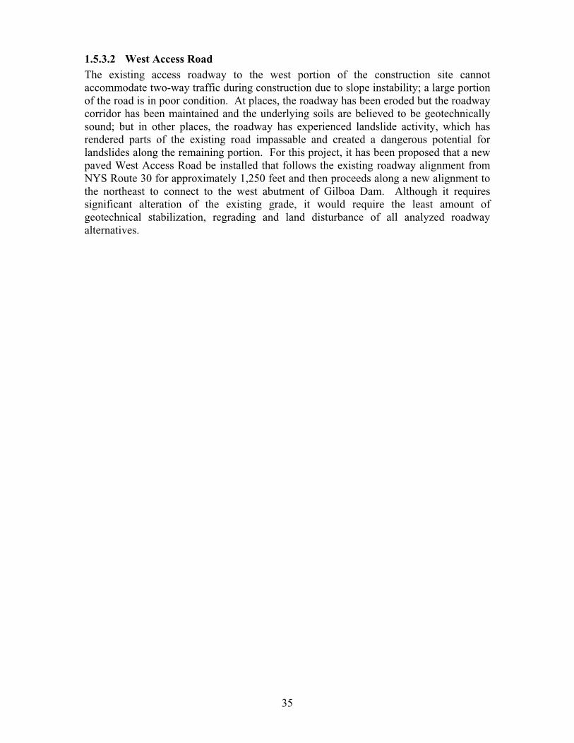
35
1.5.3.2 West Access Road The existing access roadway to the west portion of the construction site cannot accommodate two-way traffic during construction due to slope instability; a large portion of the road is in poor condition. At places, the roadway has been eroded but the roadway corridor has been maintained and the underlying soils are believed to be geotechnically sound; but in other places, the roadway has experienced landslide activity, which has rendered parts of the existing road impassable and created a dangerous potential for landslides along the remaining portion. For this project, it has been proposed that a new paved West Access Road be installed that follows the existing roadway alignment from NYS Route 30 for approximately 1,250 feet and then proceeds along a new alignment to the northeast to connect to the west abutment of Gilboa Dam. Although it requires significant alteration of the existing grade, it would require the least amount of geotechnical stabilization, regrading and land disturbance of all analyzed roadway alternatives.
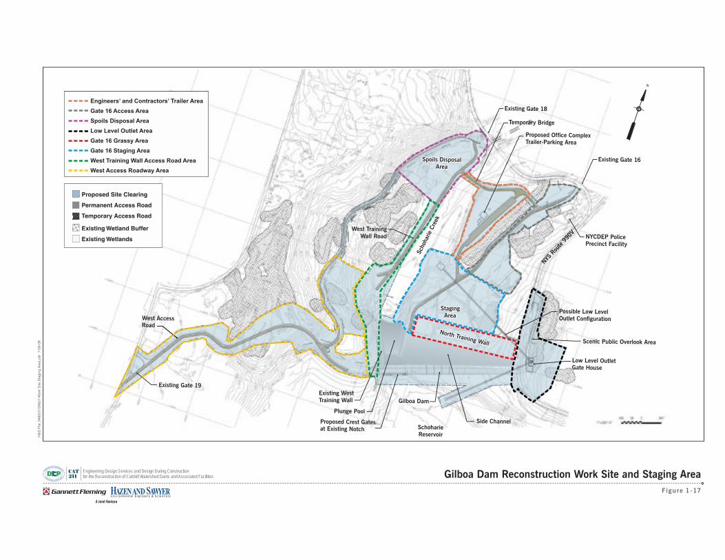
N
A Joint Venture
Gilboa DamGilboa Dam
Figure 1-17
Gilboa Dam Reconstruction Work Site and Staging Area
West Access Road
Existing Gate 19
Possible Low Level Outlet Configuration
West TrainingWall Road
NYS
Rou
te99
0V
Low Level OutletGate House
Scenic Public Overlook Area
SchoharieReservoir
Side Channel
North Training Wall
North Training Wall
StagingArea
StagingArea
Spoils DisposalArea
Spoils DisposalArea
Sch
ohar
ieCre
ek
Sch
ohar
ieCre
ek
CAT
211
Engineering Design Services and Design During Constructionfor the Reconstruction of Catskill Watershed Dams and Associated Facilities
H&
SF
ile:9
480\
310\
Mp1
-Wor
kS
iteS
tagi
ngA
rea.
cdr
7-08
-08
Proposed Site Clearing
Permanent Access Road
Temporary Access Road
Existing Wetland Buffer
WetlandsExisting
Engineers’ and Contractors’ Trailer Area
Gate 16 Access Area
Spoils Disposal Area
Areas East of Dam
Gilboa Grassy Area
LLO Area
West Training Wall Access Road
West Access Roadway
Engineers’ and Contractors’ Trailer Area
Gate 16 Access Area
Spoils Disposal Area
Low Level Outlet Area
Gate 16 Grassy Area
Gate 16 Staging Area
West Training Wall Access Road Area
West Access Roadway Area
Existing Gate 18
Temporary Bridge
Proposed Office Complex Trailer-Parking Area
Plunge Pool
Proposed Crest Gates at Existing Notch
Existing Gate 16
NYCDEP PolicePrecinct Facility
Existing West
Training Wall
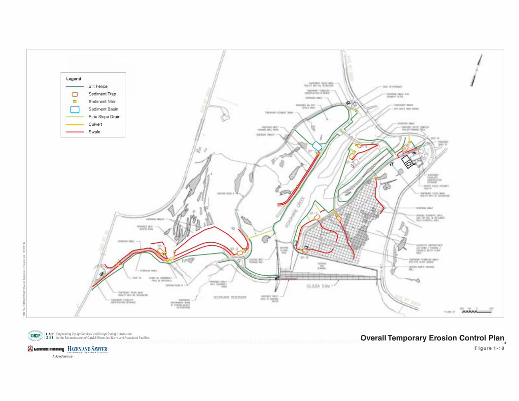
A Joint Venture
CAT
2 1 1
Engineering Design Services and Design During Constructionfor the Reconstruction of Catskill Watershed Dams and Associated Facilities
F igure 1-18
Overall Temporary Erosion Control Plan
H&
SF
ile:9
480\
310\
Mp1
-Ove
rall
Tem
pora
ryE
rosi
on.c
dr07
-09-
08
Legend
Silt Fence
Sediment Trap
Sediment filter
Sediment Basin
Pipe Slope Drain
Culvert
Swale
38
1.5.3.3 West Training Wall Access Road An entirely new roadway would be constructed to connect the West Training Wall (discussed in Section 1.5.5.2, West Training Wall) and the spoils disposal area (discussed in Section 1.5.4, Spoils Disposal Area & Temporary Internal Bridge). The West Training Wall Access Road would be graded and surfaced to produce a 24-foot wide roadway similar to the West Access Road. Upon completion of the reconstruction work, the West Training Wall Access Road would remain a permanent access structure for long-term operation and maintenance of the facility but would be reduced to a width of 16 feet during site restoration, as described in Section 2.6, Natural Resources.
1.5.3.4 Road 8 An existing road, designated as Road 8, connects to the west side of Gilboa Dam to NYS Route 990V and was built as part of the original Dam construction. A number of landslides have been reported along Road 8 that have encroached into the roadway, causing unstable ground upslope and downslope of the roadway alignment and making Road 8 in its current condition unsafe for long-term access. During reconstruction of the Dam, some improvements may be made to Road 8 to facilitate contractor access but it is not envisioned to be a major construction access point and is not anticipated to be required for future access to the west abutment of the Dam.
1.5.4 Spoils Disposal Area and Temporary Internal Bridge A spoils disposal area would be provided onsite to store the majority of spoils generated during excavation and grading activities as well as concrete rubble produced during heavy Dam reconstruction (as described in Section 1.5.5, Gilboa Dam Reconstruction). It would be capable of accommodating 95 percent of the estimated 200,000 cubic yards of spoils produced during the proposed project; the remaining 5 percent of spoils would be disposed of offsite. In order to facilitate truck traffic to and from the spoils disposal area, a temporary internal bridge traversing Schoharie Creek would be erected to provide a pathway to the Site Staging Area. This temporary internal bridge would be supported on the bottom of Schoharie Creek with vertical reinforced concrete drilled piers that are cast-in-place against in-situ rock and soil foundation so that the structure could withstand a flooding event. In addition, a vehicle wash station, as described in Section 1.5.3, Construction Site Access, would be provided at the Schoharie Creek crossing. Upon completion of the project, the spoils disposal area would be covered with soil and be replanted and the temporary internal bridge would be removed.
1.5.5 Gilboa Dam Reconstruction
1.5.5.1 Crest Gates In order to prepare the 220-foot-long Spillway notch for the installation of the pneumatically operated crest gates, approximately 2,200 square feet of 6” concrete would be removed and replaced with higher strength concrete. The anchor bolts used to connect the air bladders to the notch foundation and pneumatic airlines would be installed during this time within the new concrete. Once complete, the air bladders, crest gates and associated piping, appurtenances and control equipment would be installed. With the crest gate system installed and operational, NYCDEP would have limited control over the top five feet of Reservoir pool level and can limit Spillway overtopping resulting from
39
smaller reoccurring storm events over the remainder of the Spillway during the major Dam reconstruction work.
1.5.5.2 West Training Wall Based on the results of the geotechnical subsurface investigation described in Section 1.5.1.1.2, a retaining structure in the form of a 265-foot extension of the West Training Wall has been included in the proposed work to provide resisting force to improve slope stability and to prevent continual erosion or scour of the toe of the slope caused by high stream flows. To accommodate future possible movement of the natural hillside slope behind the proposed West Training Wall extension, flexible wall systems would be considered in addition to a rigid concrete wall. Possible flexible wall types may include mechanically stabilized earth (MSE) walls and soldier beam and lagging walls. An MSE wall consists of reinforced soil backfill that is protected by a facing system. A soldier beam and lagging wall is constructed of vertical members supporting horizontal members that retain the soil backfill. Although not as flexible as MSE walls, soldier beam and lagging walls can allow for some deflection. Both wall types can be installed in a variety of foundation conditions. Another possible configuration for the wall extension that would be considered is a short height wall with rock embedded backslope, such as riprap or articulated concrete blocks underlain by geotextile or graded soil filter, as needed. The wall height would likely be between 10 and 25 feet and armoring behind the wall would consist of riprap or other erosion resistant material. For the shorter wall height, a gabion wall would be considered in addition to the flexible wall types listed above and the rigid wall types.
1.5.5.3 North Training Wall Berm A portion of excavated material generated during site regrading activities would be used to construct a 25,000 cubic yard 13.5 foot fall armored earthen berm approximately 30 feet upstream of the North Training Wall of the Side Channel. The berm would run the full 1,290 foot length of the North Training Wall. In addition to minimizing the volume of spoils produced during site preparation, the reuse of excavated material for a berm would aid in the prevention of overtopping flow from the North Wall and erosion to the topography downstream of the Side Channel.
1.5.5.4 Masonry Reconstruction Approximately 90,000 cubic yards of the existing deteriorated stone façade from the Spillway, Stair-Steps, Plunge Pool, Side Channel, West Training Wall and overflow structures would be removed and replaced with new high-strength concrete produced onsite in a portable concrete batch plant. The Spillway would be reconfigured as the new Stair-Step structure described in Section 1.5.1.1.3, Design. As previously mentioned, approximately 65 percent of the dark gray-brown sandstone veneer has been lost due to harsh weather; and while not integral to the Dam’s structure, the veneer is a functional component of the hydraulic engineering design and operation of the Spillway. The stone removal work would occur in sections so that the portion of the Dam not under reconstruction would remain operational and all removed deteriorated stone would be stored in the spoils disposal area or disposed of offsite.
40
1.5.5.5 Low Level Outlet (LLO) The installation of the LLO described in Section 1.5.1.2, Low Level Outlet would take place during the third phase of the project concurrent with the concrete refacing of the Dam. Depending on the results of the boring program and final selection of the LLO design, a tunnel boring machine (TBM) or blasting may potentially be employed to tunnel through bedrock. All remaining excavation in non-bedrock soil would be performed manually. In-Reservoir construction, which would include a cofferdam and dewatering operation, would be required to construct the access tower described in Options 2A and 2B. Any spoils produced from this operation would be dewatered prior to disposal. All spoils created during the installation of the LLO, regardless of which alternative is selected, would be disposed of in the spoils disposal area or offsite, as discussed in Section 1.5.4, Spoils Disposal Area & Temporary Internal Bridge, and illustrated in Figure 1-17.
1.5.5.6 Upper Gate Chamber The upper gate chamber building is located aboveground and within the transition section of the western edge of the Spillway and serves as an access point to the Lower Gate Chamber, which houses the original low level outlet works. Investigations have indicated that the chamber’s superstructure is in need of repair and replacement. Therefore in the third phase of the project, the superstructure would be dismantled and completely reconstructed and facility upgrades such as lighting, ventilation, handrails, and doors to the stairway and entranceway would be installed so that the existing space could be reused. In addition, the refurbished gate chamber would be used to house the crest gate system control equipment (described in Section 1.5.1.3.3, Design).
1.5.5.7 Earthfill Embankment Dam The Earthfill Embankment Dam (Embankment) is located along the northern shore of the Schoharie Reservoir to the west of the Spillway (displayed in Figure 1-17). This section consists of homogenous soil earthfill with a concrete core wall and is separated from the Spillway portion by a massive downstream gravity wing wall. The crest of the Embankment is uneven in some areas due to long-term settlement and both the upstream and downstream Embankment slopes may not fully meet current safety standards for extreme loading cases. Under the proposed project, the placement of rock and/or earth fill materials and regrading of the Embankment section would improve the slope stability and restore the Dam crest. The tree-line would be moved approximately 20 to 30 feet back from the downstream toe of the Embankment to facilitate future facility safety and security monitoring.
1.5.6 Scenic Public Overlook Area The Scenic Public Overlook Area is positioned on the eastern edge of the Spillway and consists of several parking spaces, a platform for viewing the Reservoir and Spillway, and a kiosk that presents the Town of Gilboa history. The area is overgrown with vegetation and the fencing is failing. Under the proposed project, this area would be cleared and used as a construction staging area. Upon completion, general landscaping would be done, new and improved fencing would be installed, and the platform would be reinforced to ensure continued safety. In addition, the NYCDEP would investigate the feasibility of using recovered bluestone facing within the Scenic Public Overlook Area to
41
the Schoharie Reservoir for historical preservation purposes as per MOA with NYSOPRHP.
1.5.7 Shandaken Tunnel Intake Facility Rehabilitation NYCDEP has planned maintenance and repair to the Shandaken Tunnel Intake Facility (see Figure 1-3) to ensure continued reliability in diverting water from Schoharie Reservoir through the Shandaken Tunnel. The maintenance and repair work includes the following:
¶ Refurbishment of the Shandaken Tunnel Intake gates;
¶ Architectural, structural and utility rehabilitation of the Shandaken Tunnel Intake Building; and
¶ Other site and security improvements.
This work has been scheduled to take place during the Gilboa Reconstruction Project but would be performed independently and is not anticipated to have an environmental impact. Therefore, work associated with the improvement of the Shandaken Tunnel Intake has not been included in the environmental assessment presented in this document. Any work identified under this project would be addressed in a separate environmental review before initiation.
1.5.8 Site Restoration Following the completion of land disturbance activities as a result of reconstruction work in different portions of the project site (i.e., the West Access Road), these areas would be restored with natural vegetation., This restoration effort is described in detail in Section 2.6, Natural Resources.
1.5.9 Construction Phasing The proposed project would progress in five phases, as described below. The anticipated construction schedule provides for crest gates installation (Phase One) to commence in late 2008 and be completed at the end of 2009, site preparation activities (Phase Two) to begin in mid-2009 and be completed in late 2010 so that Dam reconstruction (Phase Three) can be completed in 2014. Rehabilitation of the Shandaken Tunnel Intake Facility (Phase 4) would take place during this time period between the fall of 2011 and the beginning of 2014. Site restoration activities (Phase 5) would take place throughout 2014. The workforce would consist of approximately 120 workers (depending on construction activities) working up to two shifts a day for a 6-day work week; the dayshift would comprise approximately 80 workers and the evening shift approximately 40 workers. Construction activities are planned for the spring, summer and fall with temporary work stoppages or limited work during the winter months (e.g., late December to early March). A proposed project schedule is presented in Attachment 3. The various phases of the Gilboa Dam Reconstruction project are discussed in greater detail in the following sections.
Phase OneThe first phase of work consists of the installation of crest gates in the existing notch. During this phase, a control building for the crest gates will be constructed and temporary
42
electrical utilities will be installed onsite to provide power to the system. The Gilboa Dam emergency work would be concluded upon completion of this phase.
Phase TwoThe second phase of the proposed work consists of preparation of the Gilboa Dam site for heavy construction which includes the establishment of primary work areas and other site preparation activities. The major activities performed in this phase would include:
¶ Clearing, Grading and Preparation of Site Staging Area
¶ Improvements of Site Access Roads including the West Access Road
¶ Preparation of Spoils Disposal Area
¶ Installation of Temporary Internal Bridge
The site preparation work would be performed in three stages, as shown in Figure 1-19,in order to provide a logical and efficient sequence of work as well as to minimize erosion and sedimentation of the work area during clearing and regrading activities.
Phase ThreeThe third phase of work consists of major Dam reconstruction activities to improve Dam and Reservoir safety, as well as the installation of the LLO. The major activities performed in the phase would include:
¶ Reconstruction of Gilboa Dam, including Spillway, Stair-Steps, Side Channel and Plunge Pool
¶ Extension and Reinforcement of the West Training Wall
¶ Refurbishment of the Upper Gate Chamber
¶ Reinforcement of the Earthfill Embankment
¶ Improvement of the Scenic Public Overlook Area
¶ Installation of the LLO
Phase FourThe fourth phase of the proposed work would consist of the Shandaken Tunnel Intake Facility rehabilitation described in Section 1.5.7, which would be performed independently of the Dam reconstruction work.
Phase FiveThe fifth and final phase of work would consist of site restoration activities to address and/or mitigate any lasting environmental effects of the Dam reconstruction. Please refer to the Natural Resources Restoration Plan in Section 2.6, Natural Resources for a description of work to be performed in this phase.
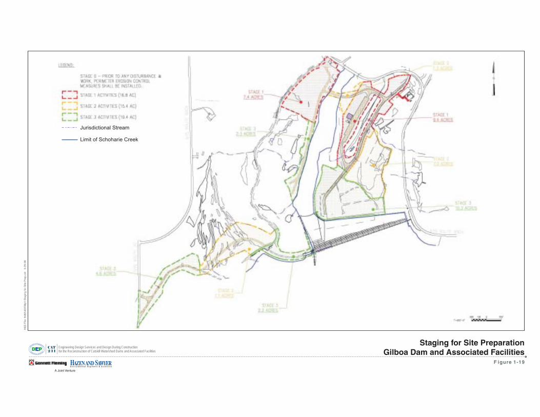
A Joint Venture
CAT
2 1 1
Engineering Design Services and Design During Constructionfor the Reconstruction of Catskill Watershed Dams and Associated Facilities
F igure 1-19
H&
SF
ile:9
480\
400\
Mp1
-Sta
ging
for
Site
Pre
p.cd
r5-
29-0
8
Staging for Site PreparationGilboa Dam and Associated Facilities
Jurisdictional Stream
Limit of Schoharie Creek
44
1.5.10 Reasonable Worst Case Scenario After reviewing the various possible construction alternatives for the proposed actions associated with each phase of reconstruction, a reasonable worst case scenario was identified. It was determined that Phase Three, Dam reconstruction would be the reasonable worst case scenario due to the fact that this Phase would result in the highest air emissions and noise during the reconstruction peak year. During Phase Three the reconstruction activities are anticipated to peak in 2012, designated as the Reconstruction Peak Year. Therefore, all impact analyses were conducted for the Reconstruction Peak Year. It is anticipated that all environmental impacts associated with reconstruction are temporary in nature and after reconstruction, no permanent impacts are anticipated.
1.5.11 Construction Provisions A number of reconstruction provisions would be implemented to minimize air emissions & noise generated by reconstruction activities to the maximum extent possible. The following list of reconstruction provisions and schedules would be implemented as part of the reconstruction project.
Work Hours
¶ Normal work hours for all phases are planned to be 6 days a week and would be restricted to begin at 7 AM and end at 10 PM during summer and 8 PM during the winter months, unless there is a major demolition cycle underway or the Contractor applies and obtains an emergency waiver from NYCDEP.
¶ No reconstruction operations would occur between 8 PM Saturday and 7 AM Monday, unless emergency or safety issues arise.
Deliveries
¶ No delivery trucks would be allowed before 7 AM or after dusk. Delivery of aggregate materials would not occur during regular Gilboa/Conesville Central School District busing times.
¶ Delivery trucks would enter at Gate 16 and travel would be restricted to the staging area located near the batch plant.
Demolition and Hauling
¶ No more than one third of the Spillway and Side Channel would be in reconstruction at one time and no more than one sixth of these areas would be under demolition at one time.
¶ During demolition cycles, demolition would end by 10 PM. Clean-up and hauling of demolition waste would be allowed to continue following that but would never continue beyond the 3 AM.
¶ No nighttime hauling (after 10 PM in summer) would be allowed offsite. Nighttime hauling would only be allowed onsite and would be limited to major demolition cycles for up to 55 days over a two year window.
¶ No Saturday and Sunday nighttime hauling would be permitted. Normal Saturday work would only include daytime activities.

45
¶ With a temporary internal bridge, trucks with a capacity of 30 cubic yards (CY) and smaller could be used for hauling with an average of four truck trips per hour to the spoils disposal area.
¶ Without a temporary internal bridge, the capacity of the hauling trucks would be limited to 12 CY, and the hauling rate would not be anticipated to exceed 12 trucks per hour. Without a temporary internal bridge, hauling operations would not be allowed during regular school transportation times for the Gilboa/Conesville Central School District.
Concrete
¶ Concrete placement would be allowed to commence as early as 4 AM during hot summer days if required.
¶ During normal operations, with concurrent reconstruction activities, no more than 600 CY per day of concrete would be manufactured. The Contractor could elect to restrict other activities and produce more concrete if the Contractor applies for a waiver and demonstrates that this is a reasonable substitution of activities relative to air quality and noise.
Paving
¶ At least 600 feet of the Gate 16 driveway from NYS Route 990V (the main site access road) would be paved.
¶ With a temporary bridge, paving would be required from the temporary internal bridge to the Gate 18 driveway.
¶ Without a temporary internal bridge, at least 400 feet from NYS Route 990V and the Gate 18 driveway of the new lower access road would be additionally paved.
¶ The batch plant would be equipped with a dust collector that would provide at least 99 percent control efficiency for PM2.5 and PM10 emissions associated with transfer of sand, aggregate, and cement to the batch plant silos.
Code Compliance
¶ The proposed project will be undertaken in accordance with the New York City Noise Code.
¶ The proposed project will comply with New York City Local Law 77.
Restoration
¶ Once work is complete in a particular section of the site, temporary restoration would be implemented within 14 days, which would be followed by a final restoration. The final restoration shall conform to the Natural Resources Restoration Plan (see Section 2.6.6) and shall be implemented in phases commencing as soon as contractually possible but no later than the next available planting season.
46
1.5.11.1 Best Management Practices – Air Emissions In addition to the above reconstruction provisions, Best Management Practices (BMPs) have been identified and would be employed to limit air emissions generated by the reconstruction activities. The Contractor will be required to submit an air quality control plan that shall, as a minimum include, the following BMPs. The list of BMPs for air quality is presented below.
¶ Wet suppression to minimize the generation of particulate matter from excavation operations and onsite vehicle traffic, with provisions for any runoff control necessary for onsite paved and unpaved roadways.
¶ Secure covering of long-term material stock piles and excavated and debris stockpiles.
¶ Compacting of soil or the use of gravel to stabilize unpaved onsite roadways.
¶ Washing the wheels and bodies of vehicles before they leave the site, as necessary, with provisions for runoff control and stabilized construction entrances.
¶ Daily cleaning of roads near the entrance to the site to minimize vehicle mud/dirt carryout.
¶ Maintaining a vegetation buffer surrounding the edge of the project site that would provide visual screening of the project site.
¶ All non-road construction equipment shall be in compliance with Local Law 77.
¶ Obtain electricity from the transmission grid as soon as feasible, to reduce the use of portable generators.
¶ Signs would be posted prohibiting idling of vehicles for more than five minutes, consistent with air quality regulations.
¶ Signs would be posted prohibiting debris hauling vehicles from traveling more than five miles per hour.
1.5.11.2 Best Management Practices – Noise In addition to the above reconstruction provisions, Best Management Practices (BMPs) have been identified and would be employed to limit noise generated by the reconstruction activities. The Contractor will be required to submit a Reconstruction Noise Mitigation Plan that shall, as a minimum include, the following BMPs. The list of BMPs for noise is presented below.
¶ Develop and post a complete and accurate Reconstruction Noise Mitigation Plan. Also, create and utilize a noise mitigation training program, which would be implemented for all field-worker supervisory personnel including sub-Contractor supervisors.
¶ Maximize the setback distance between reconstruction activities and sensitive receptors, and cooperate with other facility owners or operators to coordinate work schedules so as to minimize noise impacts at the facilities.
47
¶ Enclose the onsite concrete batch plant and associated processing equipment to the extent practical.
¶ Ensure that that all housing doors of combustion engines are kept closed by using noise-insulating material mounted on the engine housing.
¶ Use portable barriers with acoustical insulation or noise-insulating fabric around all smaller, portable noise generating equipment such as compressors, generators, pumps and other such devices.
¶ Barriers should be located as close to the noise source as possible. Stockpiles of raw materials or spoils can be an effective sound barrier if strategically placed.
¶ Use quieter back-up alarms in pre-2008 model year vehicles. These alarms should be automatic adjustable alarms that self-adjust to at least 10 decibles or louder as compared to background noise. 2008 model year or newer vehicles shall be equipped with these warning devices in accordance with Occupational Safety and Health Administration (OSHA) standards.
¶ Cranes would be equipped with Hospital Grade silencers capable of producing a noise reduction of 35 dBA, jack hammers would be jacketed and have mufflers, diesel and propane generators and diesel light fixtures would have external noise enclosures to attenuate noise levels by at least 5 dBA, and impulsive noise generated by dropping spoils in truck bins with padded/rubber liners.
¶ Post signs prohibiting idling of vehicles for more than five minutes, consistent with air quality regulations.
1.5.12 Permits and Approvals Table 1-6 lists the anticipated permits and approvals for the Gilboa Dam Reconstruction work.

48
TABLE 1-4: POSSIBLE DISCRETIONARY PERMITS AND APPROVALS U.S. FEDERAL GOVERNMENTArmy Corps of Engineers¶ Dredge and Fill Permit/ Freshwater Wetlands (Clean Water Act, Section 404)
Advisory Council on Historic Preservation ¶ Memorandum of Agreement (Section 106 of the National Historic Preservation Act of
1966)NEW YORK STATEDepartment of Environmental Conservation¶ State Pollution Discharge Elimination System (SPDES); SPDES General Permit (GP-
02-01) for Storm Water Discharge from Construction Activity (Environmental Conservation Law, Article 17, Title 8; 6 NYCRR Parts 750 through 757)
¶ Water Quality Certification (Clean Water Act, Section 401) ¶ Protection of Waters Permit (Environmental Conservation Law, Article 15, Title 15;
6NYCRR Part 608) ¶ Air Permit (Environmental Conservation Law, Article 19; 6NYCRR 200-317) ¶ Water Supply Permit (Environmental Conservation Law, Article 15, Title 15; 6
NYCRR Part 601) ¶ Stream Disturbance Permit (Environmental Conservation Law, Article 15, Title 15; 6
NYCRR Part 608) ¶ Construction, Reconstruction, or Repair of Dams and Other Impoundment Structures
Permit Department of Parks, Recreation, and Historic Preservation/State Historic Preservation
Office¶ Memorandum of Agreement (National Historic Preservation Act of 1966 and the New
York State Historic Preservation Act of 1980)Department of Health¶ State Environmental Review Certification for New York Revolving Fund Program
(Public Health Law, Sections 1161 and 1162; 21 NYCRR Part 2604) ¶ Approval of Plans for Water Supply Improvements (NYCRR Title 10 Part 5-1.22) ¶ Permit to Construct and Operate Potable Water Works (NYCRR Title 10 Part 5-1.22)
Department of Transportation ¶ Highway Work Permit for Contractor’s vehicles if they exceed the weight limit of the
state road (NYS Routes 30 and 990V) ¶ Highway Work Permit (Title 17, Part 126 of NYCRR) ¶ Traffic Enhancement Permits (Title 17, Part 126 of NYCRR)
NYCDEP¶ Watershed Lands Permit/Protection of New York City Water Supply ¶ Stormwater Pollution Prevention Plan Approval
COUNTY/LOCAL ¶ No County or local permits/approvals have been identified at this time; any
requirements would be confirmed after meeting with the relevant County/local governing bodies