Embed Size (px)
Citation preview

1
The Challenges and Advances in Mixed Reality Video Technology
Richard A. Kramer, Aashutosh Y. Taikar, Warit Paweenbampen, Haya Alorayj, Surabhi Tushar Godambe
[email protected], [email protected], [email protected],
[email protected], [email protected]
Oregon State University
Abstract - Imagine attending a video conference call with multiple parties without having to determine which monitor to look at to determine who is speaking - because everyone is present in the same room via augmented virtual reality. While the basic building blocks to create such a reality [1] exist, putting the building blocks together in a practical sense is still elusive. In this paper we take the reader to the technologic forefront of the quest to make mixed reality – a reality in the mainstream. We focus on the needs, challenges and breakthroughs in the following key areas: 1) Mixed reality image capture technology: We identify
leading research and provide an analysis of mixed reality content capture technology.
2) Mixed reality encoding technology: We review recent research related to the paramount task of efficiently capturing and rendering mixed reality content for transport over networks.
3) Mixed reality streaming and display technology: We breakdown the various display technologies and identify pros and cons.
4) Advanced applications and breakthroughs: We take the reader on a tour of recent breakthroughs related to mixed reality applications (and platforms) ranging from tourism applications, to promising educational tools that apply mixed reality, to training military personnel.
5) We end by considering future research areas that may prove promising to make mixed reality common place.
Keywords—Mixed reality, virtual reality, augmented reality, 3-D video encoding, 3-D image display, mobile devices
I. INTRODUCTION In 1965 Ivan Sutherland wrote in his paper entitled “The
Ultimate Display” that “[t]he ultimate display would, of course, be a room within which the computer can control the existence of matter” [2]. While Sutherland indeed envisioned the “Ultimate Display”, little did he know of the immense challenges to implement his vision [2]. In this paper we take the reader on a virtual tour of the immense challenges and
promising technology to realize Sutherland’s “Ultimate Display”. We start by describing the landscape of “Mixed Reality”.
Figure 1: Virtual Reality Continuum [3]
As shown in Figure 1, there is a continuum of virtual
experiences that begin with our “Real environment” (far left) that ultimately leads to a full “Virtual environment” (far right). Between these two extremes is “Augmented reality” (middle-left) which augments our reality with, for example, a holographic image of a real device (see Figure 2, [4]). Moving along the continuum of virtual experiences, “Augmented virtuality” (middle-right) combines both real world and virtual elements to create a hybrid real-world/virtual experience. On the far right is a full “Virtual environment”, often generally referred to as “Virtual Reality” (VR). In this paper, we collectively refer this continuum of virtual experiences, which often intermix, as “Mixed Reality” (MR) overall.
Figure 2: ZSpace: a turn-key holographic display [4]
While the applications and implementations of Mixed
Reality (MR henceforth) continues to grow, so does the technological challenges. MR pushes the technological limits
“The ultimate display would, of course, be a room within which the computer can control the existence of matter” Ivan Sutherland, 1965 [4].
“The ultimate display would, of course, be a room within which the computer can control the existence of matter” Ivan Sutherland, 1965 [2].
2
of multimedia in virtually every multimedia technology area ranging from image and content capture, to encoding technology, to streaming technology and display technology [5], whereas realistic content is typically a union of Virtual Reality (VR henceforth), Augmented Reality (AR henceforth) and holographic 3-D video technology [6].
While the challenges to implement MR as a mainstream technology are great, so are the benefits to those that successfully implement MR. For example: MR significantly influences consumer buying behavior. In fact, one survey of 1,300 adults reported that 53% of consumers were more likely to purchase a brand advertised via VR based on the personal connection that VR is able to establish between the consumer and the advertiser [7][8]. Among respondents, the most desired VR application that users seek (74% of respondents) related to applications for “travel and adventure” – image that before booking a hotel reservation, you could research the hotel on-line by experiencing being there [7][8]. Based on such demand, it is estimated that in the US alone, there will be 136 million users of VR by 2025.
II. MOTIVATION AND CONTRIBUTION Based on the abovementioned demand for MR, our
motivation for writing this paper is to take the reader to the forefront of research related to MR. Specifically, we focus in a number of core areas that are further discussed below.
In Section III, “Mixed Reality Image Capture Technology”, we identify leading research and provide an analysis of MR content capture technology. For example, such MR capture technology includes capture technology of not only the received MR content, but MR content generated from the user, including the ability to relate virtual objects with real-world objects so that a user can physically interact with the MR experience [9].
In Section IV, “Mixed Reality Encoding Technology”, we review the recent research in the paramount task of encoding MR content for transport over the network. For example, we consider unique research for rendering and then encoding 360-degree views. ([5] at pg. 72).
In Section V, “Mixed Reality Display Technology”, we breakdown the various display technologies, identify the problems and propose solutions based on leading research. For example, we consider research related to 3-D visualization displays that are easy to use.
In Section VI, “Advanced Applications and Breakthroughs”, we take you on a tour of recent breakthroughs related to MR applications (and platforms) ranging from tourism, to entertainment, advertising, and education.
III. MIXED REALITY IMAGE CAPTURE TECHNOLOGY
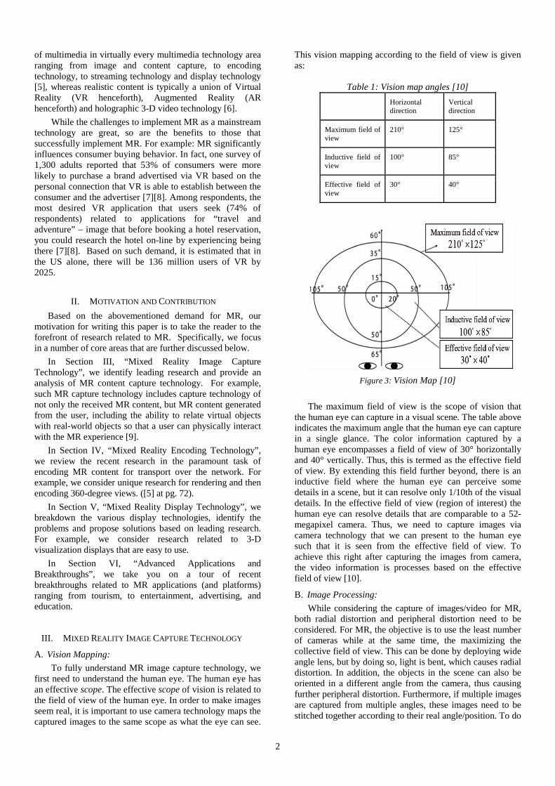
A. Vision Mapping: To fully understand MR image capture technology, we
first need to understand the human eye. The human eye has an effective scope. The effective scope of vision is related to the field of view of the human eye. In order to make images seem real, it is important to use camera technology maps the captured images to the same scope as what the eye can see.
This vision mapping according to the field of view is given as:
Table 1: Vision map angles [10] Horizontal
direction Vertical direction
Maximum field of view
210° 125°
Inductive field of view
100° 85°
Effective field of view
30° 40°
Figure 3: Vision Map [10]
The maximum field of view is the scope of vision that
the human eye can capture in a visual scene. The table above indicates the maximum angle that the human eye can capture in a single glance. The color information captured by a human eye encompasses a field of view of 30° horizontally and 40° vertically. Thus, this is termed as the effective field of view. By extending this field further beyond, there is an inductive field where the human eye can perceive some details in a scene, but it can resolve only 1/10th of the visual details. In the effective field of view (region of interest) the human eye can resolve details that are comparable to a 52-megapixel camera. Thus, we need to capture images via camera technology that we can present to the human eye such that it is seen from the effective field of view. To achieve this right after capturing the images from camera, the video information is processes based on the effective field of view [10].
B. Image Processing: While considering the capture of images/video for MR,
both radial distortion and peripheral distortion need to be considered. For MR, the objective is to use the least number of cameras while at the same time, the maximizing the collective field of view. This can be done by deploying wide angle lens, but by doing so, light is bent, which causes radial distortion. In addition, the objects in the scene can also be oriented in a different angle from the camera, thus causing further peripheral distortion. Furthermore, if multiple images are captured from multiple angles, these images need to be stitched together according to their real angle/position. To do

3
this, tracking and positioning is required. Tracking is achieved by coupling the respective cameras with sensors like gyroscopes, magnetic sensors (compasses), accelerometers, etc. [11].
Figure 4: 3-D vs VR [1][12]
C. Difference between 3-D holoscopic video and VR:
3-D video used in VR applications has a goal of providing maximum immersion to the viewer to experience a real-world like feel. 3-D holoscopic video employs a multi-view video (MVV) format that capture images horizontally by synchronizing horizontally displaced cameras. Capturing 3-D video is a cumbersome process unlike the 2-D AR video which requires less image processing and hardware. While recording a 3-D video requires two or more cameras, a 2-D AR video can be recorded using a single camera. Thus, 3-D video capturing is implemented by capturing a scene from multiple points of view, whereas the 2-D AR video capture is achieved by capturing a scene from a single point view which makes it easier to capture, render and display 2-D AR video. To ensure seamless 3-D VR video capture and display, the process requires reference parameters to be encoded along with the 3-D VR video. The biggest advantage of 3-D video is that the viewer can also see the scenes behind the user’s actual eye scope, thus providing an extended scope. This causes the user to experience a real visual feel of the video. 3-D VR can also be extended to AR which integrates the 3-D VR video, overlapped on the real-world images. AR with 3-D video can be further extended into MR, which allows the user to interact with the video objects in real time. Various challenges are seen in integrating 3-D video into AR and MR due to the many parameters to be considered while recording a 3-D video for AR and MR applications [5].
D. Tracking and positioning in video for Mixed Reality: Unlike the photo stitching, stitching of video is entirely
different and complex. This is because there are multiple images to be stitched and merged together. The human eye’s persistence of vision [10] can be used advantageously so that there is negligible detectable difference at the corners of a field of vision. This can be done using image processing and by referencing the video corners to coordinates obtained by a sensor, such as a gyroscope or a magnetometer sensor. Tracking can be categorized as inside-out (unpredictable environments) and outside-in (predictable environments). The tracking and positioning of an image can be achieved by two primary methods and one secondary tracking method:
1) Sensor Based Tracking 2) Vision Based Tracking 3) Hybrid Tracking
1) Sensor Based Tracking Image processing is computationally complex requiring
significant processing time, resources and power. Even if we totally rely on the image processing, the quality of the video will not be perfectly seamless. Instead, the processor will struggle to predict the corners of the image or video. Thus, to capture an MR video we cannot totally rely on image processing. The aim of an MR image or video is that the MR image or video should portray reality or emulate reality. To accomplish this, we need to take a reference point of real-world coordinates and parameters such that the video looks similar to reality. Due to MEMS (Micro Electro-Mechanical Systems), today many sensors are inexpensive. For example, smart-phones use a wide range of sensors like an accelerometer, gyroscope, magnetometer, etc. already embedded on a chip within the smart phone, thus making it easier to implement MR on smart phones. By using accelerometer, the camera orientation and position can be known and the video can be captured accordingly. Adding a gyroscope increases the stability of the video being captured and references the video to direction and inertia information. A magnetometer may further be used to know the exact real-world coordinates. Further, sonar sensors and ultrasonic sensors can be incorporated to measure the exact distance between an object and the camera, however sonar and ultrasonic sensors are currently expensive, and thus are not as applicable for widespread commercial use [3].
Figure 5: Sensor based tracking [13]
Challenges:
By using sensors, MR video can be tracked according to the real-world coordinates and orientation, however, sensor based tracking does have a number of limitations. For example, accelerometer and gyroscope sensors introduce tilt errors that occur during the initial calibration process. Such errors are a result of imperfections in the semiconductor production process of MEMS sensors. Minor errors in the calibration process can introduce significant errors related to MR video tracking. Also, the surrounding noise and other external factors need to be considered because the sensed data can be erroneous due to these factors. Alternative sensors can be uses such as GPS, however, if GPS is used, line of sight communications must be maintained, otherwise, the video encoding will be highly affected resulting in the real-world objects becoming de-referenced from other virtual objects [3]. Approach:
If individual sensors are used there is a very high probability of capturing incorrect reference data with the captured image. Therefore, multiple sensors can be used

4
when one sensor fails due to external conditions. For example, if an MR video sample is to be captured and the video is captured by taking the reference of GPS co-ordinates, when the video capturing device is brought indoors the GPS signal attenuates to a level that the co-ordinates have a high offset error. Thus, while the capturing device is brought indoors an accelerometer, gyroscope and magnetometer, can be used simultaneously to generate coordinates close to that of the GPS position coordinates. Furthermore, RFID technology can be used to facilitate higher accuracy, however, this approach is not always practical and does have numerous limitations [11]. 2) Vision Based Tracking
In addition to sensor based tracking, another tracking technology is vision based tracking, utilizing advanced image processing implemented within the software and hardware platform. Today, many ICs are coupled with high precision Digital Signal Processors (DSPs). DSPs highly enhance the efficiency of image processing for resolutions up to 4K. By utilizing the capability of these DSPs, the MR video captured can be referenced to other visual objects like markers and/or LEDs. By applying this approach, the real-world elements can be referenced according to the marker positions. Marker based technology was used to demonstrate a system called “Sixth-Sense” that used markers and gestures to interact with the physical world objects, thus bringing the user closer to MR [3]. Challenges:
Marker based techniques used in MR video are sometimes not suitable over different lighting conditions. This is because objects within the captured MR video can have silhouettes, causing the objects to differ from the reference objects [13]. Capturing this silhouette strains the image processor. Tracking via marker based systems have additional limitations including the fact that the image can be only processed after a certain output threshold is met. This eventually increases the computational requirements. Subsequently, using marker based tracking for natural scene applications is suboptimal, making it difficult to estimate references in a scene [11].
Opportunities:
Marker based tracking methods can be improved by adding new algorithms for image processing that have less error. Fast image processing ICs can be used to eliminate offset errors between real and virtual world objects. To improve this, many of the DSPs used in such systems employ Zhang’s algorithm [10] to calibrate and render a group of images (frames). Zhang’s algorithm is a very useful tool because it allows us to know the object coordinates and use them to eliminate error due to the pose estimation [11]. Zhang’s algorithm can be used if there are more than (or equal to) three objects, and thus is a method to eliminate the need of tracking and/or positioning [10]. 3) Hybrid Tracking:
Hybrid tracking is the fusion of sensor based and vision based tracking. Hybrid tracking eliminates various drawbacks of individual tracking techniques. Both sensor based and vision based tracking is used to form a rigid
system which can correct for errors caused exclusively in sensor based or vision based systems. For example, a GPS sensor, accelerometer, gyroscope, and magnetometer can be used in conjunction with capturing video content. To enhance the content, textures, corners, shades, etc. are added by the image processing unit to output a perfectly aligned MR video [12].
IV. MIXED REALITY ENCODING TECHNOLOGY Viewing MR content requires a special kind of head
mounted display, where the user can move his or her head in an immersive 360-degree space in all directions. Head Mounted Displays (HMDs) include: Occulus Rift, Google Cardboard, and Microsoft HoloLens as examples (see Section V, “Mixed Reality Display Technology” for more details). The MR content is shot using multiple cameras in different orientations such that they collectively represent a 360° space with enough overlap for stitching the images together [14]. The video streams are then synchronized, stitched together, projected and then compressed using various types of encoding technology. Encoding the MR video streams using standard encoders require the videos to be in a planar 2-D format and not in a 3-D immersive environment. The 3-D to 2D mapping is done using various mapping schemes so as to provide the most accurate planar format of the video.
Mapping techniques can be broadly categorized into two categories.
1) Uniform quality mapping: All the parts of the image are stretched onto the 360-degree sphere and mapped with uniform quality.
2) Non uniform mapping: More quality bits are reserved for the parts of the image that the user is currently viewing. The rest of the images are at a lower quality level.
A few of the examples of the uniform mapping are
equi-rectangular projection, cubemap projection, tile segmentation scheme, and rhombic dodecahedron scheme, whereas pyramid mappings and offset cubemap mapping fall under variable quality mapping schemes. The following sections provide a more detailed explanation of these mapping schemes, starting with a discussion about two different mapping approaches for efficient sphere to plane mapping.
A. Viewport Adaptive Encoding: MR systems make use of omnidirectional video and
HMDs with stereoscopic capabilities to create a sense of complete immersion [15]. With increasing resolution of video, now reaching up to 4K resolution, it has become very complex to encode, store and stream such omnidirectional video. Because the human eye’s perception has a certain degree of freedom, the end client will never view the entire 360-degree space at the same time. Viewport adaptive encoding exploits this fact and encodes and streams only the part that the end user is viewing at any given point in time. A number of the viewport dependent mapping schemes are discussed as follows:

5
1) Rhombic Pyramid Mapping A pyramid is a complex polyhedron with a polygonal
base whereas each edge from the base connects to an apex. This particular mapping technique was proposed by Facebook. Here we are only considering a regular pyramid. The entire 360-degree view on the sphere is intricately mapped onto the base and the sides of the pyramid.
Figure 6: Square Pyramidal Mapping and Projection [15]
The base of the pyramid is a rhombus. The current viewport (e.g., a polygon viewing area). of the user is mapped onto the base and thus, is kept at a higher resolution. The resolution keeps decreasing as we map the right, left, upward viewports because these viewports are not within the primary focus of the user. The viewport that is directly at the back of the user has the least resolution since it is not in view. As seen in Figure 6, after mapping, the 3-D pyramid is unwrapped to form a planar view. The faces are then resized and recentered to have a regular planar shape. Several versions of 360-degree content are encoded for different front face orientations. In total, to cover an entire sphere, the system must encode 30 different orientations, separated by about 30 degrees each [15]. 2) Square Pyramid Mapping
A regular pyramid has sharp diagonal edges between the front and the side faces which reduce coding efficiency. To avoid this, square pyramid mapping is proposed. The pyramid is rotated in such a way that the diagonal edges are aligned with the axes of the image. This helps to preserve continuity along the sides of the front face [15]. The frame packing is as shown in Figure 7.
Figure 7: Square Pyramidal Mapping and Projection [15]
3) Truncated Pyramidal Square Mapping In this scheme, the top or the apex of the original
pyramidal structure is truncated to reduce the edges; by doing so, this technique provides better coding efficiency. The projection and frame packing is shown in Figure 8, below.
Figure 8: Truncated Pyramidal Mapping and Projection [15]
4) Multi-resolution, Equi-rectangular and Cubemap
Projection Most of the rendering engines are designed to be either
an ERP (Equi-rectangular Projection) system or a CMP (Cubemap Projection) system. The frame arrangement for CMP is shown in the Figure 9 and the frame arrangement for ERP is shown in Figure 10. In both CMP and ERP, the current viewport is streamed at a higher resolution, while the remaining part of the 360-degree field of view is re-sampled and packed in such a way that it can be packed into a rectangular box which occupies the same number of pixels as that of the front face [15]. Figure 9 below shows only one of the many ways to pack the frame into the rectangular box. There can be many ways to optimally pack the frame that leads to improved coding efficiency. These arrangements can be coded separately as individual segments.
Figure 9: Multi-resolution Cubemap Projection[15]
Figure 10: Equirectangular Projection [15]
B. Object -based coding This type of video coding is used in MPEG-4. As the
name implies, this technique identifies and segregates the shape of moving objects in a particular frame from the stationery background and then encodes the objects separately. In this type of video coding, pseudo-cylindrical projections are used for 3-D to planar mapping. An example is shown in Figure 11. The type of projection is categorized based upon the shape of meridians to sinusoidal, elliptical, parabolic, hyperbolic, rectilinear, hammer, etc. [16].
Figure 11: Pseudo-cylindrically projected original bear attack
sequence [16]

6
It has been determined that hammer projections provide optimal performance for head movement [16][17]. This technique also improves the stereoscopic rendering of virtual environment performance. To handle arbitrary boundary shapes for object-based coding, methods have been devised to fill empty pixels with the mean value of the surrounding pixels.
C. Coding of Pseudo-Cylindrical Panoramas Intra-frame coding or panoramas suffer from
substantial coding inefficiency due to sharp edges at the boundaries of the effective image area. The inter frame coding has inefficiencies due to the fact that all of the pixel values are not available in the areas close to the boundaries. The mismatch in the block being encoded and the prediction block in the reference frame causes additional error [16]. To help with the intra-frame error, which has the average value from the non-effective areas, pixels close to boundaries should be replaced by pixel values that are more correlated to the effective areas of the frame. The results of this process are shown in Figure 12. The improved correlation can then be easily processed in the DCT and quantization steps. In this method, for each row of the boundary block, the pixels on the border of the image’s effective area are replicated to the non-effective part of the boundary [16].
Figure 12: Boundary block padded [16]
Figure 13: Manipulated reference frame [16]
To additionally improve inter-frame coding efficiency,
we can further make use of the 360-degree characteristics of the image. If a sphere is opened up in a pseudo-cylindrical fashion, it can be noticed that every left-most pixel is considered to be adjacent to the right-most pixel. Thus, in the reference frames, the samples can be replicated from the
edges of the image to fill in the non-effective areas. This creates better continuity at the boundary of the image as is further shown in Figure 13.
Figure 14: Encoder Block Diagram [16]
Figure 15: Decoder Block Diagram [16]
Figure 14 and Figure 15 show the HEVC (High Efficiency Video Codec) encoding and decoding process used in conjunction with the proposed improvements discussed above. As shown in Figure 14 for the encoding process, each reconstructed frame is passed to the Reference Frame Padding (RFP) unit before the information is filtered (F) and stored in the Reference Frame Memory (RFP). The RFP unit manipulates each frame by copying extreme side samples to create continuity in the boundary regions. These redundant pixels are not coded because doing so would significantly increase the bitrate. As shown in Figure 15, in the decoding process, the same steps are applied but in the reverse order. The decoded frames are passed onto the OC (Output Cropping – denoted as “C” above) unit to extract the pseudo-cylindrical panorama from the manipulated format. The samples outside effective area set to initial values.
V. MIXED REALITY DISPLAY TECHNOLOGY There are many different MR technologies and
subsequently, many types of MR devices. The various types of MR devices can be categorized into two groups: (1) input and (2) output MR device [18]. For the input category of devices, data is received through a controller device, a navigation device, or a tracking device. Conversely, for output devices, the output data can be displayed as visual, haptic, or multisensory content. For further information, see Figure 16 [18].
In this section, we will focus mainly on visual output devices and techniques, and more specifically, visual mobile

7
techniques, which are both portable and affordable. At the center of MR display technology is the Head Mounted Display (HMD).
Figure 16: Visual reality technology categories [18]
A. Head Mounted Display (HMD) The HMD is a critical tool that MR systems use. To
understand the challenges that face MR streaming, we have to understand how the HMD works. In the book “Head-Mounted Displays” [19], James Melzer defines the HMD as a device that can send and receive personal data through sight and physical interaction. The HMD provides the user with the ability to view 360-degrees in three different axes. While that could be considered an advantage, it has a significantly negative impact on bandwidth.
B. Visual output device The category of visual output devices is divided into
mobile output devices and wired output devices. For mobile output devices, we will present and compare two popular technologies from two competing companies: Google and Samsung. We will illustrate other papers and research as well. Finally, we will evaluate and compare output devices based on a number of important factors. We have selected the devices in this study based on device popularity, efficient performance, and best user experience [18].
C. Google Cardboard: Google Cardboard leverages new smart phone
technology combined with HMD technology [18].
Figure 17: Google Cardboard [20]
As shown in Figure 17, the device consists of a simple
headset and a smart phone. Google cardboard has many advantages, which are:
1) Can be used anywhere. 2) Compatible with most smart phones. 3) Very light and portable. 4) A very affordable price which make it available for
everyone [21].
Google Cardboard is used frequently in various MR research projects based on its advantages. In the paper, “Getting Around in Google Cardboard – Exploring Navigation Preferences with Low-Cost Mobile VR”, the researchers (Powell et al.) focused on how they could add new features to Google Cardboard to evaluate the level of compatibility and flexibility. The research mainly focused on adding three new features related to movement (which they call “travel”) and control. The new features that the researchers added are: (1) they implemented a magic stick and linked it with a smart phone; (2) they added a controller to stop and start the device; (3) they added a Bluetooth controller to increase the control capabilities of the device, through the use of a mini joystick.
The researchers tried to add an additional feature to the Bluetooth controller that would allow the user to step both right and left, however, the additional feature caused negative sides effects such as nausea, and thus the feature was not added. Table 2 below, show the results for one experiment related to control and movement (e.g., travel).
Table 2: The three travel techniques evaluated in the study [21]
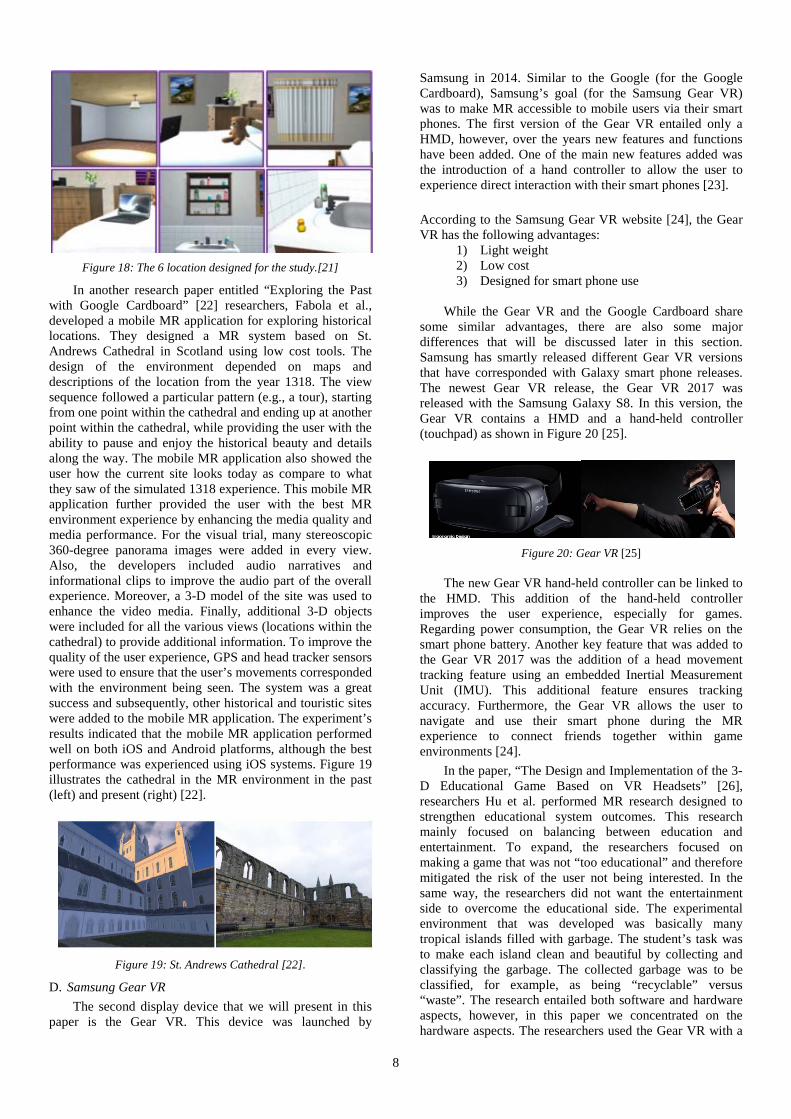
In the experiment, the researchers measured Google Cardboard’s ability to navigate complex and simple tasks in an open MR environment. The researchers further built a MR environment with six locations to visit, as depicted in Figure 18, along with the abovementioned three added features. Based on user feedback, the most important feature was the user’s ability to move freely. The results of the experiments highlighted Google Cardboard’s advantages [21].
8
Figure 18: The 6 location designed for the study.[21]
In another research paper entitled “Exploring the Past with Google Cardboard” [22] researchers, Fabola et al., developed a mobile MR application for exploring historical locations. They designed a MR system based on St. Andrews Cathedral in Scotland using low cost tools. The design of the environment depended on maps and descriptions of the location from the year 1318. The view sequence followed a particular pattern (e.g., a tour), starting from one point within the cathedral and ending up at another point within the cathedral, while providing the user with the ability to pause and enjoy the historical beauty and details along the way. The mobile MR application also showed the user how the current site looks today as compare to what they saw of the simulated 1318 experience. This mobile MR application further provided the user with the best MR environment experience by enhancing the media quality and media performance. For the visual trial, many stereoscopic 360-degree panorama images were added in every view. Also, the developers included audio narratives and informational clips to improve the audio part of the overall experience. Moreover, a 3-D model of the site was used to enhance the video media. Finally, additional 3-D objects were included for all the various views (locations within the cathedral) to provide additional information. To improve the quality of the user experience, GPS and head tracker sensors were used to ensure that the user’s movements corresponded with the environment being seen. The system was a great success and subsequently, other historical and touristic sites were added to the mobile MR application. The experiment’s results indicated that the mobile MR application performed well on both iOS and Android platforms, although the best performance was experienced using iOS systems. Figure 19 illustrates the cathedral in the MR environment in the past (left) and present (right) [22].
Figure 19: St. Andrews Cathedral [22].
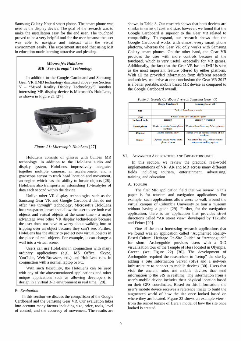
D. Samsung Gear VR The second display device that we will present in this
paper is the Gear VR. This device was launched by
Samsung in 2014. Similar to the Google (for the Google Cardboard), Samsung’s goal (for the Samsung Gear VR) was to make MR accessible to mobile users via their smart phones. The first version of the Gear VR entailed only a HMD, however, over the years new features and functions have been added. One of the main new features added was the introduction of a hand controller to allow the user to experience direct interaction with their smart phones [23]. According to the Samsung Gear VR website [24], the Gear VR has the following advantages:
1) Light weight 2) Low cost 3) Designed for smart phone use
While the Gear VR and the Google Cardboard share
some similar advantages, there are also some major differences that will be discussed later in this section. Samsung has smartly released different Gear VR versions that have corresponded with Galaxy smart phone releases. The newest Gear VR release, the Gear VR 2017 was released with the Samsung Galaxy S8. In this version, the Gear VR contains a HMD and a hand-held controller (touchpad) as shown in Figure 20 [25].
Figure 20: Gear VR [25]
The new Gear VR hand-held controller can be linked to
the HMD. This addition of the hand-held controller improves the user experience, especially for games. Regarding power consumption, the Gear VR relies on the smart phone battery. Another key feature that was added to the Gear VR 2017 was the addition of a head movement tracking feature using an embedded Inertial Measurement Unit (IMU). This additional feature ensures tracking accuracy. Furthermore, the Gear VR allows the user to navigate and use their smart phone during the MR experience to connect friends together within game environments [24].
In the paper, “The Design and Implementation of the 3-D Educational Game Based on VR Headsets” [26], researchers Hu et al. performed MR research designed to strengthen educational system outcomes. This research mainly focused on balancing between education and entertainment. To expand, the researchers focused on making a game that was not “too educational” and therefore mitigated the risk of the user not being interested. In the same way, the researchers did not want the entertainment side to overcome the educational side. The experimental environment that was developed was basically many tropical islands filled with garbage. The student’s task was to make each island clean and beautiful by collecting and classifying the garbage. The collected garbage was to be classified, for example, as being “recyclable” versus “waste”. The research entailed both software and hardware aspects, however, in this paper we concentrated on the hardware aspects. The researchers used the Gear VR with a
9
Samsung Galaxy Note 4 smart phone. The smart phone was used as the display device. The goal of the research was to make the installation easy for the end user. The touchpad proved to be a very helpful tool for the user because the user was able to navigate and interact with the visual environment easily. The experiment stressed that using MR in education made learning attractive and pleasing.
Microsoft’s HoloLens
MR “See-Through” Technology
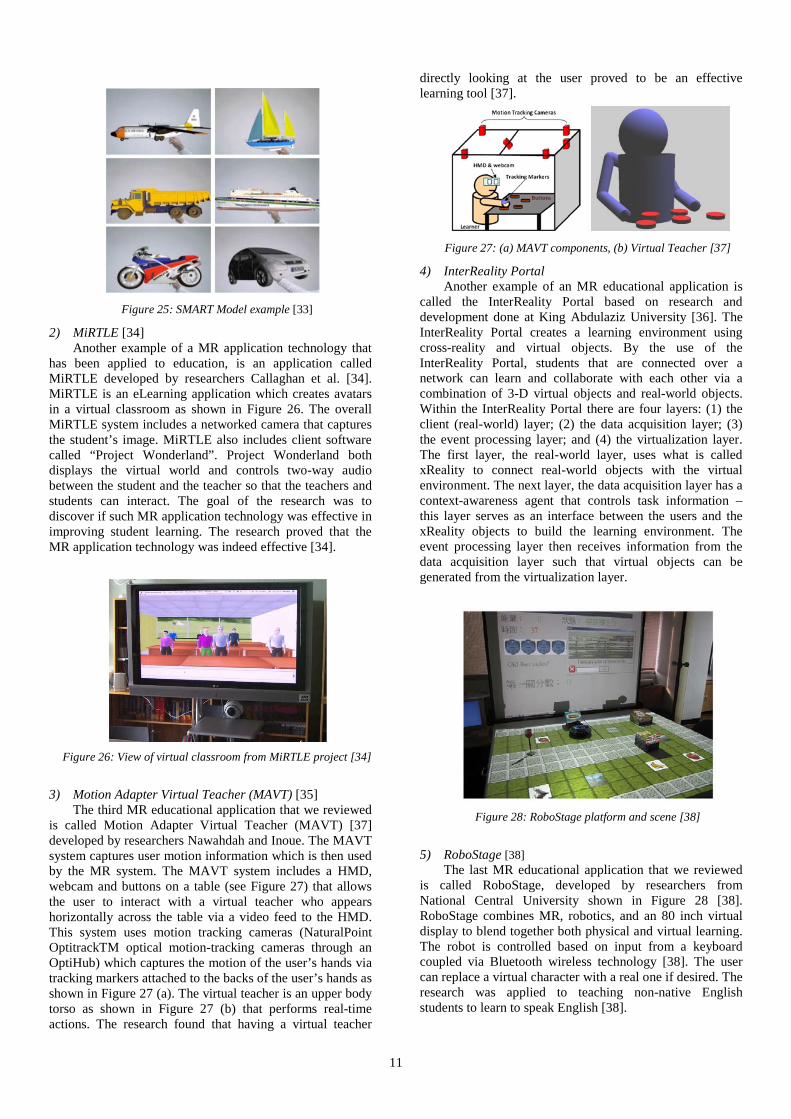
In addition to the Google Cardboard and Samsung Gear VR HMD technology discussed above (see Section V – “Mixed Reality Display Technology”), another interesting MR display device is Microsoft’s HoloLens, as shown in Figure 21 [27].
Figure 21: Microsoft’s HoloLens [27]
HoloLens consists of glasses with built-in MR
technology. In addition to the HoloLens audio and display system, HoloLens impressively integrates together multiple cameras, an accelerometer and a gyroscope sensor to track head location and movement, an engine which has the ability to locate objects [28]. HoloLens also transports an astonishing 10-terabytes of data each second within the device.
Unlike other VR display technologies such as the Samsung Gear VR and Google Cardboard that do not offer “see through” technology, Microsoft’s HoloLens has transparent lenses that allow the user to see both real objects and virtual objects at the same time - a major advantage over other VR display technologies because the user does not have to worry about walking into or tripping over an object because they can’t see. Further, HoloLens has the ability to project new virtual objects in the place of real objects. For example, it can change a wall into a virtual scene.
Users can use HoloLens in conjunction with many ordinary applications (e.g., MS Office, Skype, YouTube, Web-Browsers, etc.) and HoloLens runs in conjunction with a normal laptop or PC.
With such flexibility, the HoloLens can be used with any of the abovementioned applications and other unique applications such as allowing developers to design in a virtual 3-D environment in real time. [28].
E. Evaluation In this section we discuss the comparison of the Google
Cardboard and the Samsung Gear VR. Our evaluation takes into account many factors including size, price, tools, level of control, and the accuracy of movement. The results are
shown in Table 3. Our research shows that both devices are similar in terms of cost and size, however, we found that the Google Cardboard is superior to the Gear VR related to compatibility. To expand, our research shows that the Google Cardboard works with almost every smart phone platform, whereas the Gear VR only works with Samsung Galaxy smart phones. On the other hand, the Gear VR provides the user with more controls because of the touchpad, which is very useful, especially for VR games. Additionally, the fact that the Gear VR has an IMU is seen as the most important feature offered by either platform. With all the provided information from different research and articles, we arrive at one conclusion: the Gear VR 2017 is a better portable, mobile based MR device as compared to the Google Cardboard overall.
Table 3: Google Cardboard versus Samsung Gear VR
VI. ADVANCED APPLICATIONS AND BREAKTHROUGHS In this section, we review the practical real-world
implementations of VR, AR and MR across many different fields including tourism, entertainment, advertising, training, and education.
A. Tourism The first MR application field that we review in this
paper is for tourism and navigation applications. For example, such applications allow users to walk around the virtual campus of Columbia University or tour a museum without having a guide [29]. Further, for the navigation application, there is an application that provides street directions called “AR street view” developed by Takusho and Feiner [29].
One of the most interesting research applications that we found was an application called “Augmented Reality-Based Cultural Heritage On-Site Guide” or “Archeoguide” for short. Archeoguide provides users with a 3-D visualization tour of the Temple of Hera located in Olympia, Greece (see Figure 22) [30]. The development of Archoguide required the researchers to “setup” the site by adding a Site Information Server (SIS) and a network infrastructure to connect to mobile devices [30]. Users that visit the ancient ruins use mobile devices that send information to the SIS in realtime. The information from a user’s mobile device includes their physical location based on their GPS coordinates. Based on this information, the user’s mobile device receives a reference image to build the augmented world of how the site once looked based on where they are located. Figure 22 shows an example view - from the ruined temple of Hera a model of how the site once looked is created.

10
Figure 22: (a) Actual ruins of the temple of Hera, (b) Augmented
reality of ruins of temple of Hera [30]
While Archeoguide was only developed for a single site, imagine the future when tourists can see the ruins of an ancient site or other historical sites as an alternative to looking at a picture. Such technology makes such tourist sites more interesting which consequently attracts more visitors. Similarly, such technology can be applied to the education field where students can learn history first hand, for example, students that go to a museum and see a virtual historical site so that they can understand the significance of certain artifacts much quicker. This is just one reason why using MR in the tourism field will truly be beneficial.
Other interesting research that we found in this field entailed the implementation of MR technology located at the Orlando Science Center’s DinoDigs Exhibition Hall [31]. On exhibit at the Orlando Science Center is an ancient fossil of a sea creature that went extinct over a million years ago as is shown in Figure 23. Using MR technology, the sea creature is brought back to life again using a spherical screen and projector [31]. Once the virtual guide on the screen finishes explaining the significance of the sea creature, a virtual experience begins, complete with water and then the fossil turns into a virtual living creature. Although no human knows how the extinct ancient sea creature actually looked, using MR technology makes the experience much more interesting. While the deployment of MR within the tourism industry is limited today, surely based on what we have discussed above, MR technology can greatly enhance the tourism industry.
Figure 23: Example of MR technology that displays a virtual sea creature at the Orlando Science Center’s DinoDigs Exhibition
Hall [31]
B. Entertainment and Advertising The second MR application field that we review in this
paper is in the field of entertainment and advertising. In this section we include gaming applications as part of entertainment applications. Cleary, one of the largest attractions to MR is that people find the MR experience
fascinating and enjoyable. Mobile devices have further driven the popularity of MR applications, especially MR applications for gaming. For example, Pokemon Go, a well-known mobile game that was launched in 2016 has had enormous success; generating up to 2 million US dollars per day in revenue [29]. This game uses MR based technology along with smart phone GPS location information to allow users to interact with characters hidden at different locations. For at home games, the Microsoft Kinect device - a device with a motion sensor, greatly enhances the user experience by capturing the user’s motion, thus allowing games to simulate the user as a character within the overall game environment [29].
Figure 24: AR technology on a mobile game application called
Pokemon GO [32]
Additionally, advertising opportunities exist within virtual environments. For example, advertisers can market products with a MR environment (such as displaying a Starbucks branded coffee cup). If the user expresses interest in a particular product, then the advertiser can provide additional information to the user.
C. Training and Education The third and final MR application field that we review in
this paper is in the field of training and education. In this section we look at a number of interesting educational applications including SMART [33], MiRTLE [34], Motion Adapter Virtual Teacher (MAVT) [35], the InterReality Portal [36], and applications for training military personnel [29][31].
1) SMART [33]
One such application developed for teaching school children in the second grade is an application called “SMART” developed by Freitas and Campos [33]. The SMART system allows students to learn within a 3-D environment as shown in Figure 25 . With the affordable price of smart phones and tablets, more and more MR applications are being developed to help children to learn better, where research has proven such MR technology is effective in improving the overall performance of students [29] [33].
11
Figure 25: SMART Model example [33]
2) MiRTLE [34] Another example of a MR application technology that
has been applied to education, is an application called MiRTLE developed by researchers Callaghan et al. [34]. MiRTLE is an eLearning application which creates avatars in a virtual classroom as shown in Figure 26. The overall MiRTLE system includes a networked camera that captures the student’s image. MiRTLE also includes client software called “Project Wonderland”. Project Wonderland both displays the virtual world and controls two-way audio between the student and the teacher so that the teachers and students can interact. The goal of the research was to discover if such MR application technology was effective in improving student learning. The research proved that the MR application technology was indeed effective [34].
Figure 26: View of virtual classroom from MiRTLE project [34]
3) Motion Adapter Virtual Teacher (MAVT) [35]
The third MR educational application that we reviewed is called Motion Adapter Virtual Teacher (MAVT) [37] developed by researchers Nawahdah and Inoue. The MAVT system captures user motion information which is then used by the MR system. The MAVT system includes a HMD, webcam and buttons on a table (see Figure 27) that allows the user to interact with a virtual teacher who appears horizontally across the table via a video feed to the HMD. This system uses motion tracking cameras (NaturalPoint OptitrackTM optical motion-tracking cameras through an OptiHub) which captures the motion of the user’s hands via tracking markers attached to the backs of the user’s hands as shown in Figure 27 (a). The virtual teacher is an upper body torso as shown in Figure 27 (b) that performs real-time actions. The research found that having a virtual teacher
directly looking at the user proved to be an effective learning tool [37].
Figure 27: (a) MAVT components, (b) Virtual Teacher [37]
4) InterReality Portal Another example of an MR educational application is
called the InterReality Portal based on research and development done at King Abdulaziz University [36]. The InterReality Portal creates a learning environment using cross-reality and virtual objects. By the use of the InterReality Portal, students that are connected over a network can learn and collaborate with each other via a combination of 3-D virtual objects and real-world objects. Within the InterReality Portal there are four layers: (1) the client (real-world) layer; (2) the data acquisition layer; (3) the event processing layer; and (4) the virtualization layer. The first layer, the real-world layer, uses what is called xReality to connect real-world objects with the virtual environment. The next layer, the data acquisition layer has a context-awareness agent that controls task information – this layer serves as an interface between the users and the xReality objects to build the learning environment. The event processing layer then receives information from the data acquisition layer such that virtual objects can be generated from the virtualization layer.
Figure 28: RoboStage platform and scene [38]
5) RoboStage [38]
The last MR educational application that we reviewed is called RoboStage, developed by researchers from National Central University shown in Figure 28 [38]. RoboStage combines MR, robotics, and an 80 inch virtual display to blend together both physical and virtual learning. The robot is controlled based on input from a keyboard coupled via Bluetooth wireless technology [38]. The user can replace a virtual character with a real one if desired. The research was applied to teaching non-native English students to learn to speak English [38].

12
6) Training Military Personnel [29][31] Not only can MR technology be used for training
school children, but also military personnel, thus allowing military personnel to gain experience before they face real danger. For example, MR technology has been deployed so that users can feel what is like to be in the shoes of a U.S. Navy Seal performing a rescue mission [39][40]. Another example of an MR application for training military personnel is called MOUT [31] as shown in Figure 29. MOUT uses “video see-through” technology (see discussion in call-out box “Microsoft’s HoloLens - MR ‘See-Through’ Technology” above). To expand, the application sets up a small urban site battle field on a blue screen. The computer generates the environment, characters, props, etc. [31]. Within the virtual environment the user can move around and practice within the virtual battlefield. The researchers, Hughes et al., point out that the most powerful result is that the virtual characters can perform like actual people, which has proven highly effective in training [31].
Figure 29: MR MOUT set up area and simulation [31]
Yet another application developed for training military personnel is an application that assists soldiers performing maintenance on LAVs (Light Armored Vehicles) [29]. The application displays important information including labels and arrows to help soldiers identify critical components within the LAV-25. The application can be controlled by using buttons or a slider. The application runs on a game engine providing 800 x 600 resolution at 75 fps (frames per second). The application has proven useful because the soldiers do not have to carry books and instructions manuals. It is said that the application makes it so easy to maintenance the LAV, that anyone can do the maintenance even if they have not had any prior training [29].
VII. CONCLUSION In this paper we have highlighted promising new
technology, including: • We reviewed the pros and cons of using various sensor
technologies in conjunction with 3-D technology to provide the absolute best union between the user and the virtual MR experience.
• We considered the effective field of view that a user can see and contemplate the merits of applying precious
image processing resources only where such resources would be most useful - where the user is actually looking.
• We reviewed the merits of various encoding technologies via various 360-degree mapping schemes to provide the absolute best use of precious video bandwidth.
• We took the reader on a tour of the various types of MR display technologies and considered the advantages and disadvantages of each.
• We ended with a review of promising new applications that would benefit society the most and as a result, push MR technology into mainstream acceptance rather than just a niche market.
Researchers will no doubt continue to rise to challenge of bringing Ivan Sutherland’s “ultimate display” [2] to the masses, based on enabling technologies in the areas of image capture technology, MR encoding technology, and MR streaming and display technology.
VIII. BIBLIOGRAPHY
[1] 3dglasses101, "3dglasses101," 24 June 2014. [Online]. Available: https://3dglasses101.wordpress.com/2014/06/29/3d-glasses-a-technology-worth-the-wait/.
[2] I. E. Sutherland, "The Ultimate Display," Information Processing Techniques Office, ARPA, OSD, 1965.
[3] G. Singh and A. Mantri, "Ubiquitous Hybrid Tracking Techniques for Augmented Reality Applications," in IEEE Proceedings of 2015 RAECS UIET Panjab University Chandigarh, Chandigarh, India, 2015.
[4] Doc-OK.org, "A developer's perspective on immersive 3D computer graphics, Zspace: a turn-key holographic display," 26 January 2013. [Online]. Available: http://doc-ok.org/?p=322. [Accessed 21 April 2017].
[5] A. Kondoz and T. Dagiuklas, Novel 3D Media Technologies, New York, New York: Springer, 2015.
[6] H. Park, H. Yoon and J. Hwang, "Prospect of the Next-generation digital content industry: Three perspective approach to the User acceptance of the Realistic content technology," in IEEE/ICACT 2016 : 18th IEEE International Conference on Advanced Communications Technology, Phoenix Park, PyeongChang, Korea, 2016.
[7] M. Swant, "New Study Says People Are More Likely to Buy From Brands That Use Virtual Reality," AdWeek, 2016.
[8] StartVR, "STUDY: CONSUMERS MORE LIKELY TO BUY FROM BRANDS USINO VR," 2016. [Online]. Available: https://startvr.co/vr-study/. [Accessed 20 April 2017].
[9] D. Sellami, K. Marwa and M. Krid, "A survey of AR systems and a case study of virtual keyboard based camera projector system," in IEEE IPAS’16: INTERNATIONAL IMAGE PROCESSING APPLICATIONS AND SYSTEMS CONFERENCE 2016, Hammamet, Tunisia, 2016.

13
[10] Z. Gong, W. Peng, X. Zhang and X. Shi, "Reasearch on VIrtual Reality Image Processing System Based on Medical Platformaper," in IEEE, 2015.
[11] E. Marchand, H. Uchiyama and F. Spindler, "Pose Estimation for Augmented Reality: A Hands-On Survey," 2016.
[12] Joe, "gizmochina," 29 Feb 2016. [Online]. Available: http://www.gizmochina.com/2016/02/29/vr-box-is-an-enhanced-google-cardboard-version-for-30/.
[13] D. P. Kaur and A. Mantri, "Computer Vision and Sensor fusion for efficient Hybrid Tracking in Augmented Reality Systems," in IEEE, 2015.
[14] M. Hafeeda and T. El-Ganainy, "Streaming Virtual Reality Content," 2016.
[15] K. Shreedhar, A. Alireza, H. Miska and G. Moncef, "Viewport-adaptive Encoding and Streaming of 360 degree Video for Virtual Reality Applications," 2016.
[16] R. Youvalar, A. Aminlou, M. Hannuksela and M. Gabbouj, "Coding of 360-Degree Pseudo-Cylindrical Panoramic Video for Virtual Reality Applications," in 2016 IEEE International Symposium on Multimedia, 2016.
[17] H. Debarba, S. Perrin, B. Herbelin and R. Boulic, "Embodied interaction using non planar projections in immersive virtual reality," in Proceedings of 21st ACM Symposium on Virtual Reality Software and Technology, 2015.
[18] C. Anthes, R. J. García-Hernández, M. Wiedemann and D. Kranzlmüller, "State of the art of virtual reality technology," in 2016 IEEE Aerospace Conference, Big Sky, MT, 2016.
[19] J. Melzer, "Head-Mounted Displays," in Digital Avionics Handbook, 2014, pp. 257-280.
[20] "Google Cardboard," Google, [Online]. Available: https://vr.google.com/cardboard/. [Accessed May 2017].
[21] W. Powell, V. Powell, P. Brown, M. Cook and J. Uddin, "Getting Around in Google Cardboard – Exploring Navigation Preferences with Low-Cost Mobile VR," in 2016 IEEE 2nd Workshop on Everyday Virtual Reality (WEVR), Greenville, SC, 2016.
[22] A. Fabola, A. Fawcett and R. Miller, "Exploring the Past with Google Cardboard," in 2015 Digital Heritage, Granada, 2015.
[23] "UPLOAD," [Online]. Available: https://uploadvr.com/review-gear-vr-2017-galaxy-s8-daydream-comparison/. [Accessed May 2017].
[24] "Know Your Mobile," [Online]. Available: http://www.knowyourmobile.com/wearable-technology/samsung-gear-vr/23504/samsung-gear-vr-2017-review-virtual-reality-specs-price-features-release-date-detailed-examined-vs-google-daydream-view. [Accessed MAy 2017].
[25] "Samsung," Samsung, [Online]. Available: http://www.samsung.com/global/galaxy/gear-vr/. [Accessed May 2017].
[26] X. Hu, R. Su and L. He, "The Design and
Implementation of the 3D Educational Game Based on VR Headsets," in 2016 International Symposium on Educational Technology (ISET), Beijing, 2016.
[27] Ramadhanakbr, "Microsoft Hololens," 1 October 2016. [Online]. Available: https://commons.wikimedia.org/wiki/File:Ramahololens.jpg. [Accessed 10 May 2017].
[28] ColdFusion, "Microsoft Hololens Explained! - The Future Of Computing," 13 May 2015. [Online]. Available: https://www.youtube.com/watch?v=NwY-6sQDYnk. [Accessed 9 May 2017].
[29] D. Chatzopoulos, C. Bermejo, Z. Huang and P. Hui, "Mobile Augmented Reality Survey: From Where We Are to Where We Go," IEEE Access, 2017.
[30] V. Vlahakis et al., "Archeoguide: an augmented reality guide for archaeological sites".IEEE Computer Graphics and Applications.
[31] C. E. Hughes, C. B. Stapleton, D. E. Hughes and E. M. Smith, "Mixed reality in education, entertainment, and training," IEEE Computer Graphics and Applications, Nov.-Dec 2005.
[32] K. T. Jensen, "Screenshot of the video game Pokémon Go with Doduo and a Poké Ball," Niantic, 13 July 2016. [Online]. Available: https://en.wikipedia.org/wiki/File:Pokemon_Go_screenshot.jpg. [Accessed 10 May 2017].
[33] R. Freitas and P. Campos, "SMART: a SysteM of Augmented Reality for Teaching 2nd Grade Students," 2008.
[34] V. Callaghan, M. Gardner, B. Horan, J. Scott, L. Shen. and M. Wang, "A Mixed Reality Teaching and Learning Environment," Hybrid Learning and Education, 2008.
[35] D. Poelman and R. van Krevelen, "A Survey of Augmented Reality Technologies, Applications and Limitations".
[36] A. PEÑA-RIOS, V. CALLAGHAN, M. GARDNER and a. M. ALHADDAD, "The InterReality Portal: A Mixed Reality Cocreative Intelligent Learning Environment".
[37] M. Nawahdah and a. T.Inoue, "Setting the best view of a virtual teacher in a mixed reality physical-task learning support system".
[38] C.-W. Chang, J.-H. Lee, C.-Y. Wang and G.-D. Chen, "Improving the authentic learning experience by integrating robots into the mixed-reality environment".
[39] Navy Recruiting Command Public Affairs, "US Navy Showcases Cutting-Edge Virtual Reality Experience," 5 October 2016. [Online]. Available: http://www.navy.mil/submit/display.asp?story_id=97051. [Accessed 20 April 2017].
[40] L. Faw, "Navy Deploys VR Combat Simulators To Engage Potential Recruits," Mediapost.com, 11 October 2016. [Online]. Available: https://www.mediapost.com/publications/article/286634/navy-deploys-vr. [Accessed 20 April 2017].