Embed Size (px)
Citation preview
,
BNL INFORMAL REPORT BNL-62311
THE CARNOL, PROCESS SYSTEM FOR C02 MITIGATION AND METHANOL PRODUCTION
Meyer Steinberg
August 14, 1995
RECEIVED NOV 2 9 1995
O S T I
Engineering Research and Applications Division
DEPARTMENT OF ADVANCED TECHNOLOGY BROOKHAVEN NATIONAL LABORATORY, ASSOCIATED UNIVERSITIES, INC. I D I1 I P.O. BOX 5000. UPTON. NEW YORK 11973-5000
UNITED STATES DEPARTMENT OF ENERGY CONTRACT NO. DE-AC02-76-CH00016
DISCLAIMER
This report was prepared as an account of work sponsored by an agency of the United States Government. Neither the United States Government nor any agency thereof, nor any of their employees, nor any of their contractors, subcontractors, or their employees, makes any warranty, express or implied, or assumes any legal liability or responsibility for the accuracy, completeness, or usefulness of any information, apparatus, product, or process disclosed, or represents that its use would not infringe privately owned rights. Reference herein to any specific commercial product, process, or service by trade name, trademark, manufacturer, or otherwise, does not necessarily constituteor imply its endorsement, recommendation, or favoring by theunitedstates Government or any agency, contractor or subcontractor thereof. The views and opinions of authors expressed herein do not necessarily state or reflect those of the United States Government or any agency, contractor or subcontractor thereof.

THE C M O L PROCESS SYSTEM FOR C02 MITIGATION AND M E T W O L PRODUCTION
Meyer Steinberg
August 14, 1995
Engineering Research and Applications Division Department of Advanced Technology
Brookhaven National Laboratory Upton, N.Y. 11973-5OOO
ASTER .......e...

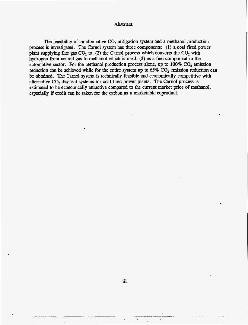
Abstract
The feasibility of an alternative CO, mitigation system an^ a methanol production process is investigated. The Camol system has three components: (1) a coal fired power plant supplying flue gas CO, to, (2) the Camol process which converts the CO, with hydrogen from natural gas to methanol which is used, (3) as a fuel component in the automotive sector. For the methanol production process alone, up to 100% CO, emission reduction can be achieved while for the entire system up to 65% CO, emission reduction can be obtained. The Camol system is technically feasible and economically competitive with alternative CO, disposal systems for coal fired power plants. The Carnol process is estimated to be economically attractive compared to the current market price of methanol, especially if credit can be taken for the carbon as a marketable coproduct.
iii

Table of Contents
. Title Page
Abstract . . . . . . . . . . . . . . . . . . . . . . . . . . . . . . . . . . . . . . . . . . . . . . . . . . iii
Table of Contents . . . . . . . . . . . . . . . . . . . . . . . . . . . . . . . . . . . . . . . . . . . . v
List of Figures . . . . . . . . . . . . . . . . . . . . . . . . . . . . . . . . . . . . . . . . . . . . . vii
List of Tables . . . . . . . . . . . . . . . . . . . . . . . . . . . . . . . . . . . . . . . . . . . . . . . ix
Introduction . . . . . . . . . . . . . . . . . . . . . . . . . . . . . . . . . . . . . . . . . . . . . . . . 1
The Cam01 System Configuration Development . . . . . . . . . . . . . . . . . . . . . . . . . . 1
Hydrogen Production with Zero CO, Generation . . . . . . . . . . . . . . . . . . . . . . . . . 2
The Synthesis of Methanol with Zero CO, Emission . . . . . . . . . . . . . . . . . . . . . . . 3
The Integrated Carnol Process System . . . . . . . . . . . . . . . . . . . . . . . . . . . . . . . . 3
Preliminary Economics . . . . . . . . . . . . . . . . . . . . . . . . . . . . . . . . . . . . . . . . . 4
Comparison of CO, Emission for the Cam01 Process and for the Entire CarnolSystem . . . . . . . . . . . . . . . . . . . . . . . . . . . . . . . . . . . . . . . . . . . . . 4
Conclusions . . . . . . . . . . . . . . . . . . . . . . . . . . . . . . . . . . . . . . . . . . . . . . . . 5
References . . . . . . . . . . . . . . . . . . . . . . . . . . . . . . . . . . . . . . . . . . . . . . . . 6
V


List of Figures
Figure Pane.
1 Carnol System Configuration For CO, Emission Mitigation . . . . . . . . . . . . . . . 7 2 Carnol VI Process for CO, Mitigation Technology .................... 8
vii

List of Tables
- Table
1 Hydrogen Production - Comparison of Basic Energy Requirements and CO, Emission. . . . . . . . . . . . . . . . . . . . . . . . . . . . . . . . . . . . . . . 9
2 Carnol Process Design Parameters Mass and Energy Balances . . . . . . . . . . . . 10
3 Preliminary Carnol Process Economics . . . . . . . . . . . . . . . . . . . . . . . . . . 11
4 Methanol Production and CO, Emission Process Comparison . . . . . . . . . . . . . 12
5 CO, Emission From System of Coal Fired Power and Liquid HC Fueled Automotive Power . . . . . . . . . . . . . . . . . . . . . . . . . . . . . . . . . . . . . 13
ix

The Carnol Process System for CO, Mitigation and Methanol Production
Introduction
The evidence for greenhouse gas CO, warming causing global climate change is continuing to mount, and international agreements are being sought to limit CO, emissions (Refs. 1 and 2). The CO, emissions are primarily due to fossil fuel combustion in the commercial, industrial and transportation sectors. In the U.S. about one-third of the CO, comes from the industrial sector mainly from central power stations which are largely fueled by coal. About an equal amount of CO, is emitted in each of the other two sectors. In this paper we describe and develop a system, the Carnol System, which converts CO, from coal-fired power plant stack gases with natural gas to produce methanol as a liquid fuel for use in automotive engines. Carbon is produced as a coproduct which is a storable commodity product. The carbon from the coal is used twice and, therefore, the CO, is greatly reduced compared to conventional system.
The Carnol System Configuration Development
The basis for the Carnol system depends on integration of the following four developments.
1.
2.
3.
4.
A significant amount of effort and improvement has gone into the removal of CO, from the stack gas of fossil fuel burning plants particularly for recovery and disposal of CO, in the ocean (Refs. 3 and 4). In the Camol configuration it is proposed to utilize the CO, rather than dispose and sequester the CO,.
For purposes of providing the hydrogen to reduce the CO, to methanol, it is proposed to thermally decompose methane (from abundant ~turai gas) to hydrogen and carbon. In order to produce hydrogen without generation of CO, it is proposed not to bum the carbon produced, but to use it as a materials commodity (Ref. 5). An alternative hydrogen production process without net CO, generation is the gasification of biomass (wood) (Ref. 6).
The synthesis of methanol has been significantly improved by using liquid phase slurry catalysts (Refs. 7 and 8). It is proposed to react the CO, saturated monoethanolamine (MEA) solvent used in the recovery of CO, from coal-fired power plant stack gases to produce the methanol.
It is proposed to use the methanol produced in the Camol system as an alternative fuel in internal combustion automotive engines in the transportation sector. It is recognized that in order to make an impact in CO, reduction, a large market for the product methanol must be available. The automotive fuel market provides that possibility. Furthermore, it is shown that methanol is 30% more efficient in IC engines than
1
conventional gasoline, thus providing further incentives for reducing CO, emissions (Ref. 9).
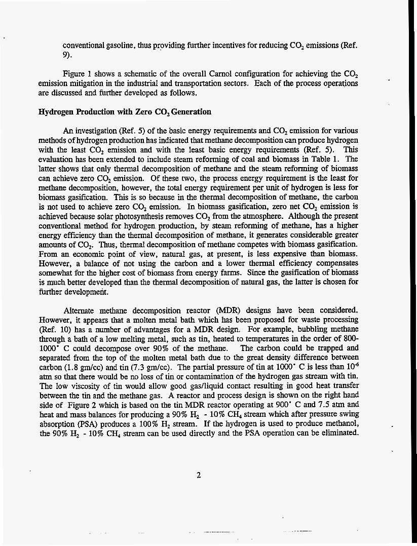
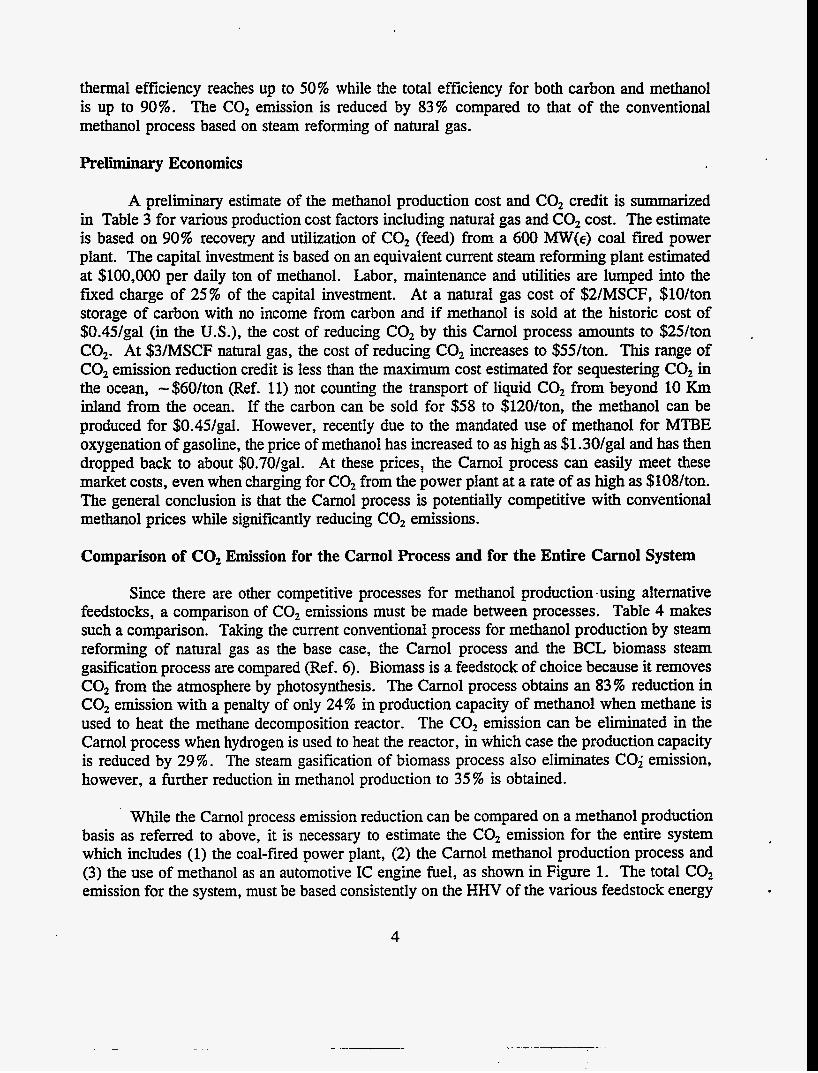
Figure 1 shows a schematic of the overall Carnol configuration for achieving the CO, emission mitigation in the industrial and transportation sectors. Each of the process operations are discussed and further developed as follows.
Hydrogen Production with Zero CO, Generation
An investigation (Ref. 5 ) of the basic energy requirements and CO, emission for various methods of hydrogen production has indicated that methane decomposition can produce hydrogen with the least CO, emission and with the least basic energy requirements (Ref. 5). This evaluation has been extended to include steam reforming of coal and biomass in Table 1. The latter shows that only thermal decomposition of methane and the steam reforming of biomass can achieve zero CO, emission. Of these two, the process energy requirement is the least for methane decomposition, however, the total energy requirement per unit of hydrogen is less for biomass gasification. This is so because in the thermal decomposition of methane, the carbon is not used to achieve zero CO, emission. In biomass gasification, zero net CO, emission is achieved because solar photosynthesis removes CO, from the atmosphere. Although the present conventional method for hydrogen production, by steam reforming of methane, has a higher energy efficiency than the thermal decomposition of methane, it generates considerable greater amounts of CO,. Thus, thermal decomposition of methane competes with biomass gasification. From an economic point of view, natural gas, at present, is less expensive than biomass. However, a balance of not using the carbon and a lower thermal efficiency compensates somewhat for the higher cost of biomass from energy farms. Since the gasification of biomass is much better developed than the thermal decomposition of natural gas, the latter is chosen for further development.
Alternate methane decomposition reactor (MDR) designs have been considered. However, it appears that a molten metal bath which has been proposed for waste processing (Ref. 10) has a number of advantages for a MDR design. For example, bubbling methane through a bath of a low melting metal, such as tin, heated to temperatures in the order of 800- 1OOO' C could decompose over 90% of the methane. The carbon could be trapped and separated from the top of the molten metal bath due to the great density difference between carbon (1.8 gm/cc) and tin (7.3 gdcc). The partial pressure of tin at 1OOO' C is less than lod atm so that there would be no loss of tin or contamination of the hydrogen gas stream with tin. The low viscosity of tin would allow good gadliquid contact resulting in good heat transfer between the tin and the methane gas. A reactor and process design is shown on the right hand side of Figure 2 which is based on the tin MDR reactor operating at 900' C and 7.5 atm and heat and mass balances for producing a 90% H, - 10% CH, stream which after pressure swing absorption (PSA) produces a 100% H, stream. If the hydrogen is used to produce methanol, the 90% H, - 10% CH, stream can be used directly and the PSA operation can be eliminated.
2
The Synthesis of Methanol with Zero C02 Emission
The hydrogen produced by methane decomposition is used to react with CO, recovered from coal fired power plant.
CO, + 3H2 = CH,OH + H,O If one mole of CO, is removed from the stack gases to produce 1 mole methanol, then
when, the methanol is combusted as fuel, one mole of CO, is produced. Therefore, the net generation of CO, for production of methanol is zero.
Using MEA solvent gases, it is reported that it requires at least 25% of the capacity of the power plant to remove and recover CO, from the stack gases of the power plant (Ref. 11). With improvement in absorber packing, the pressure drop for feeding flue gas through the absorber using a hindered amine solvent the fraction loss of power to recover 90% of the CO, from a coal burning plant is reduced to 12% (Ref. 4). About 92% of the energy is needed in the stripper portion of the recovery system which is obtained from the low pressure side of the turbine and reduces the net power output of the plant. However, if the CO, is reacted with hydrogen, methanol is produced in an exothermic reaction and that energy can be used to strip out the CO, from the MEA and therefore it becomes unnecessary to take steam from the power plant for this purpose. Furthermore, if a liquid phase slurry catalyst system is used with an MEA solvent, the heat of reaction resultbg from the synthesis of methanol is sufficient to distill out the methanol from the MEA solvent. The synthesis of methanol has an exothermic heat of reaction of 33 Kcal/gm mol CO, (or MeOH), which is more than enough to provide the heat of vaporization of methanol which is only 9 KcaVmol.
Another important point is that the equilibrium concentration of methanol produced by the reaction of CO, with H, is favored at lower temperatures. Equilibrium calculation indicates that the concentration of methanol at 120' C is 5.8 and 3.4 times that at 260' C for pressure of 30 atm and 50 atm, respectively. The higher equilibrium methanol concentration results in a lower recycle ratio around the methanol synthesis steps and a higher thermal efficiency. The equilibrium partial pressure of CO, can be obtained from the phase equilibrium diagram for the amine H,O - CO, given by Suda, et al. (Ref. 4). The liquid phase methanol slurry catalysts are under investigation by several investigators (Ref. 7). The liquid phase synthesis is favored because its heat transfer characteristics are better than the gas phase heat transfer synthesis.
The Integrated Carnol Process System
The methane decomposition molten metal reactor process can be integrated with the liquid phase synthesis of methanol, using CO, removed from a fossil fuel fired power plant. Figure 2 shows the integrated Carnol process. A computer simulation model of the entire process has been developed to obtain material and energy balances over a range of MDR and methanol synthesis reactor (MSR) conditions. A summary of one of the computer runs of the process including the performance parameters are shown in the summary of Table 2. The
3
thermal efficiency reaches up to 50% while the total efficiency for both carbon and methanol is up to 90%. The C02 emission is reduced by 83% compared to that of the conventional methanol process based on steam reforming of natural gas.
Preliminary Economics
A preliminary estimate of the methanol production cost and CO, credit is summarized in Table 3 for various production cost factors including natural gas and CO, cost. The estimate is based on 90% recovery and utilization of CO, (feed) from a 600 W(E) coal fired power plant. The capital investment is based on an equivalent current steam reforming plant estimated at $100,000 per daily ton of methanol. Labor, maintenance and utilities are lumped into the fmed charge of 25% of the capital investment. At a natural gas cost of $2/MSCF, $lO/ton storage of carbon with no income from carbon and if methanol is sold at the historic cost of $0.45/gal (in the U.S.), the cost of reducing CO, by this Carnol process amounts to $25/ton CO,. At $3/MSCF natural gas, the cost of reducing CO, increases to $%/ton. This range of CO, emission reduction credit is less than the maximum cost estimated for sequestering CO, in the ocean, -$60/ton (Ref. 11) not counting the transport of liquid CO, from beyond 10 Km inland from the ocean. If the carbon can be sold for $58 to $120/ton, the methanol can be produced for $0.45/gal. However, recently due to the mandated use of methanol for MTBE oxygenation of gasoline, the price of methanol has increased to as high as $1.30/gal and has then dropped back to about $0.70/gal. At these prices, the Carnol process can easily meet these market costs, even when charging for CO, from the power plant at a rate of as high as $108/ton. The general conclusion is that the Carnol process is potentially competitive with conventional methanol prices while significantly reducing CO, emissions.
Comparison of CO, Emission for the Carnol Process and for the Entire Carnol System
Since there are other competitive processes for methanol production -using alternative feedstocks, a comparison of CO, emissions must be made between processes. Table 4 makes such a comparison. Taking the current conventional process for methanol production by steam reforming of natural gas as the base case, the Carnol process and the BCL biomass steam gasification process are compared (Ref. 6). Biomass is a feedstock of choice because it removes CO, from the atmosphere by photosynthesis. The Carnol process obtains an 83% reduction in CO, emission with a penalty of only 24% in production capacity of methanol when methane is used to heat the methane decomposition reactor. The CO, emission can be eliminated in the Carnol process when hydrogen is used to heat the reactor, in which case the production capacity is reduced by 29%. The steam gasification of biomass process also eliminates CO; emission, however, a further reduction in methanol production to 35% is obtained.
While the Carnol process emission reduction can be compared on a methanol production basis as referred to above, it is necessary to estimate the CO, emission for the entire system which includes (1) the coal-fired power plant, (2) the Carnol methanol production process and (3) the use of methanol as an automotive IC engine fuel, as shown in Figure 1. The total CO, emission for the system, must be based consistently on the HHV of the various feedstock energy
4
inputs to the system including (a) electricity from the power plant, (b) liquid methanol fuel from the Carnol plant and (c) mechanical energy from the automotive IC engines. This was done in Table 7 for 4 systems: 1) current conventional coal fired power plant, and gasoline driven automobiles; 2) coal fired power plant with conventional natural gas steam reforming for methanol production and methanol fueled vehicles; 3) coal-fired power plant with Cam01 process for methanol production and use of methanol fueled vehicles, and 4) coal-fired power plant with biomass gasification methanol production and with methanol fueled vehicles. Several assumptions must be made for a valid comparison.
e
e
e
e
e
The oil refrnery produces gasoline at 90% efficiency; the equivalent of 10% C is lost as coz. The thermal efficiency for steam reforming of methane to methanol is 64%.
The Carnol thermal efficiency is 90 % . The net CO, emission based on biomass gasification is zero.
The methanol fueled vehicle is 30% more efficient than gasoline driven vehicle (Ref. 9).
The results shown in Table 5 indicate that the CO, emission reduction is reduced by 18% using conventional steam reforming of natural gas for methanol production and its use in vehicles. The CO, is reduced by 63 % for the Carnol methanol process and 65 % reduction when biomass gasification is used. The latter two thus achieves significant reductions in CO, emission for the entire system. From an economic point of view, the biomass feedstock is currently more expensive than natural gas in the U.S. and, therefore, for about equal CO, emission reduction, the Cam01 natural gas process presently should be more economical.
Conclusions
The Carnol process system configuration appears to be technically feasible and economically viable both as a CO, mitigation method for coal-fired power plants and as a methanol production process compared to the conventional method especially when considering credit for marketing the carbon coproduct. For process improvement, the development of a molten metal methane decomposition reactor and a CO, liquid phase catalytic slurry methanol synthesis reactor are recommended.
5
References
1. Stevens, W.K., “Scientists Warn of Effect of Rise in Greenhouse Gases,” New York Times, The Environment, p. C4, April 11, 1995.
2. Mills, E., D. Wilson, and T. Johansson, “Getting Started. No Regrets Strategies for Reducing Greenhouse Gas Emissions, ” Energy Policy, July/August 1991.
3. U.S. Department of Energy, “The Capture Utilization and Disposal of CO, from Fossil Fuel-Fired Power Plants,” Vols. I and II, Washington, D.C., 1993.
4. Suda, T., et al., “Development of Fuel Gas Carbon Dioxide Recovery Technology,” Chapter in Carbon Dioxide Chemistrv: Environment Issues, Ed. By Jon Paul and Claire- Marie Pradier, The Royal Society of Chemistry, 1994 and private communication, p. 222-35, June 1995.
5. Steinberg, M. , “The Hy-C Process (Thermal Decomposition of Natural Gas) Potentially the Lowest Cost Source of Hydrogen with the Least CO, Emission,” BNL-61364, Brookhaven National Laboratory, Upton, N.Y. , December 1994.
6. Larson E.O., and R.E. Katofsky, “Production of Hydrogen and Methanol via Biomass Gasification, ” in Advances in Thermochemical Conversion, Elsevier Applied Science, London, 1992.
7. Lee, S. , Methanol Synthesis Technolow, CRC Press, Inc. , Boca Raton, Florida, p. 198- 224, 1990.
8. Okyama, S. , “Evaluation of Low Temperature Methanol Synthesis in the Liquid Phase,” ACS Division of Fuel Chemistry, 200* ACS National Meeting 2 No. 4, Washington, D.C., p. 1182-6, August 20-25, 1994.
9. EPA Report, “An Analysis of the Economic and Environmental Effects of Methanol as an Automotive Fuel,” EPA Report No. 0730, Motor Vehicle Emissions Laboratory, AM Arbor, Michigan, September, 1989.
10. Nahass, P., P.A. Moise and C.A. Chanenchuk, “Quantum CEP for Mixed Waste Processing,” Molten Metal Technology, Inc. , Waltham, Mass. , 1994.
11. IEA Greenhouse Gas R and D Programme Report “Carbon Dioxide Capture From Power Stations, ” Cheltenham, U.K. , 1994.
6
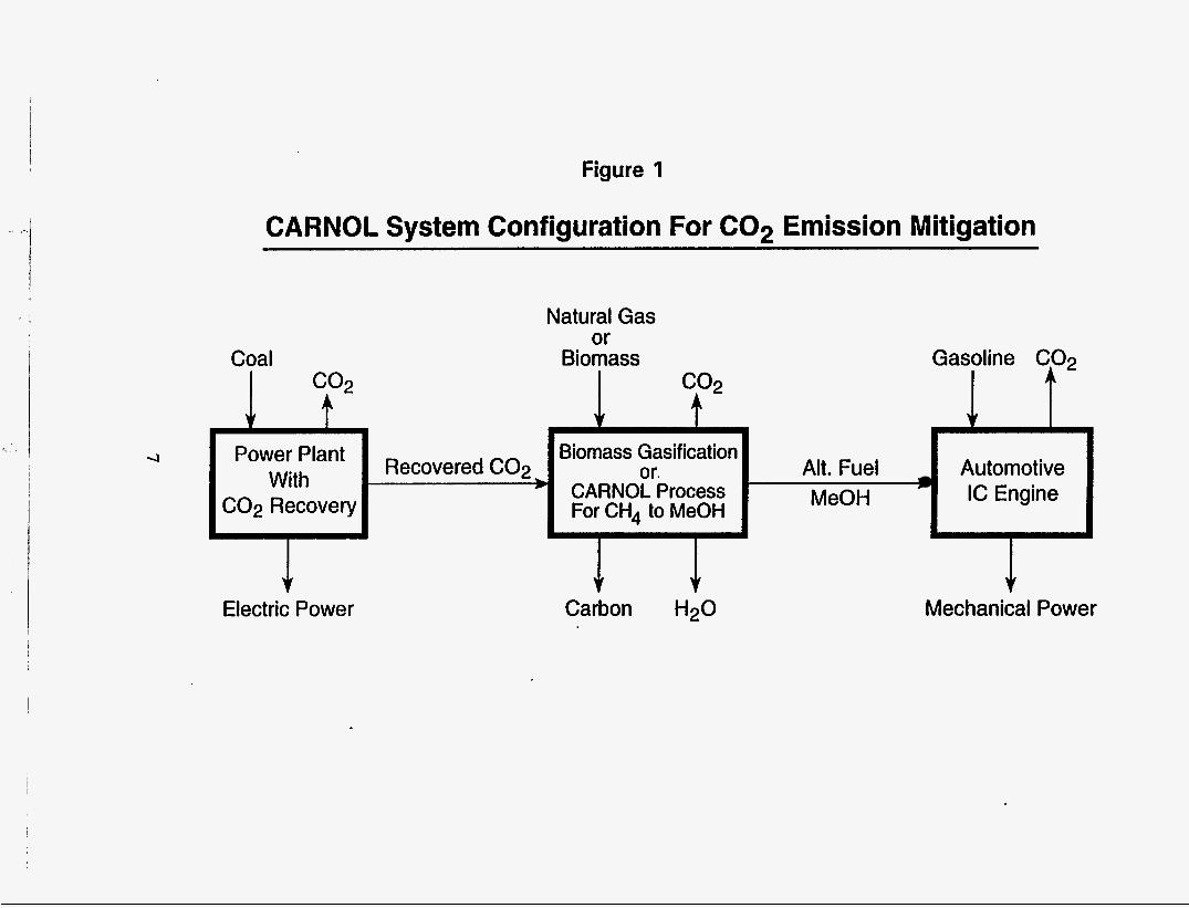
Figure I
Power ‘Iant With
C02 Recovery L
CARNOL System Configuration For C02 Emission Mitigation
Biomass Gasification
For CH4 to MeOH
Recovered C02 or. Alt. Fuel Automotive + CARNOL Process MeOH IC Engine
J r
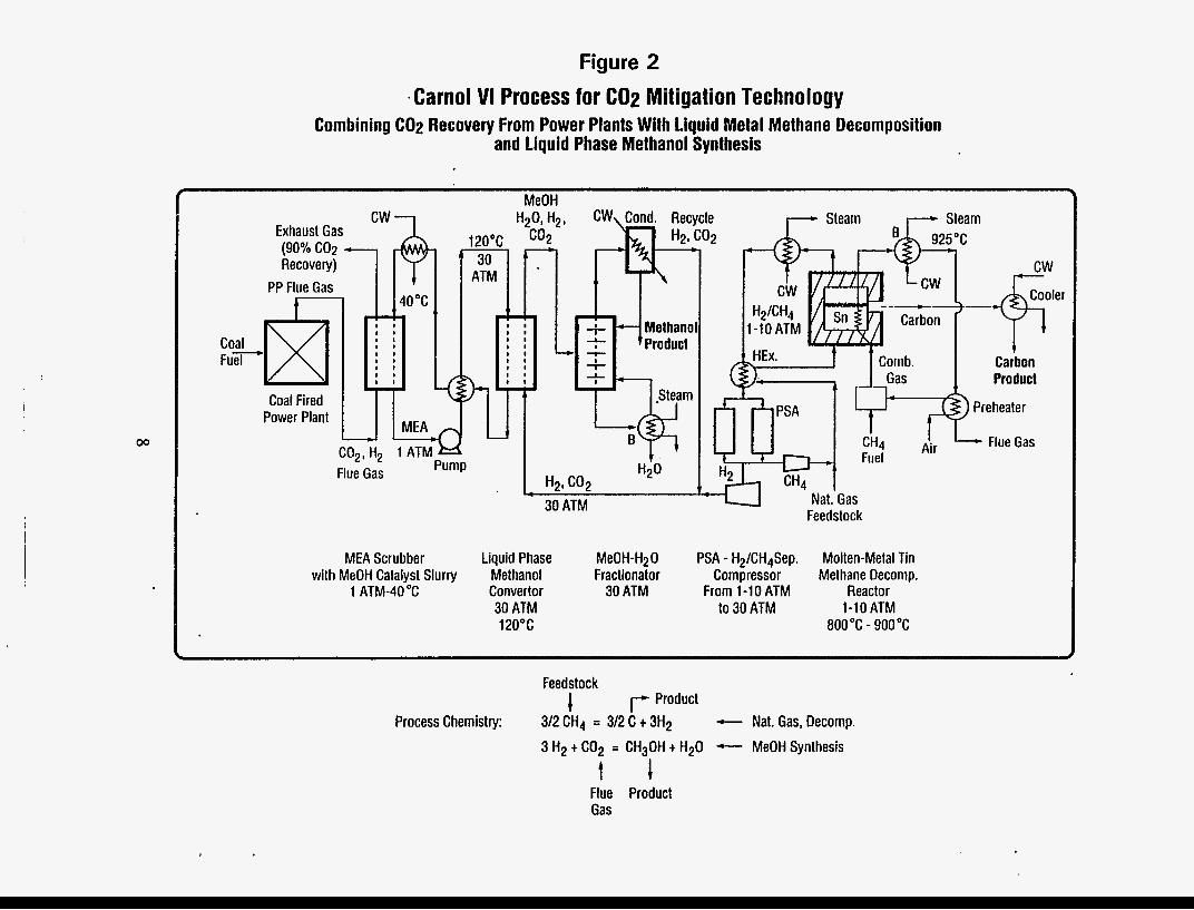
Figure 2 .Carno1 VI Process for CO2 Mitigation Technology
Combining C02 Recovery From Power Plants With liquid Metal Methane Decomposition and liquid Phase Methanol Synthesis
Coal Fired I I I Power Plant w I MEA
J u C02, H2 1 ATM )--<
Pump Flue Gas
MeOH
30 ATM
MEA Scrubber Liquid Phase with MeOH Catalyst Slurry Methanol
1 ATM-40°C Convertor 30 ATM 120°C
' Nat.'Gas Feedstock
MeOH-H20 PSA - H2/CH4Sep. Molten-Metal Tin Fractionator Compressor Methane Decomp.
30 ATM From 1-1 0 ATM Reactor to 30 ATM 1-10 ATM
800°C - 900 "C
Feedstock 1 r-- Product Process Chemistry: 312 CH4 = 312 C t 3H2 - Nat. Gas, Decomp.
3 H2 t C02 = CH30H t H20 - MeOH Synthesis
t 1 Flue Product Gas
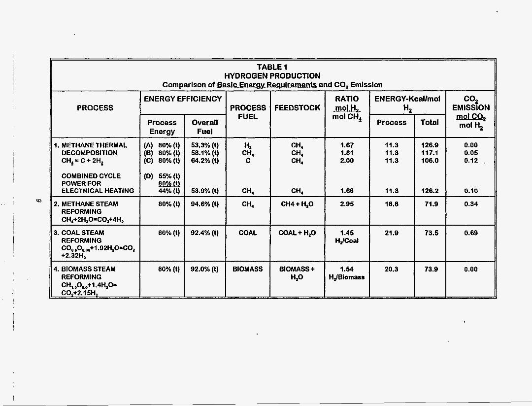
TABLE 1 HYDROGEN PRODUCTION
Comparison of Bask Enerav Req uirementg and CO, Emission I PROCESS ' FUEL
H,
C ' CH4
CH4
PROCESS RATIO ENERGY-Kcallmol
mol CH, Process Total
FEEDSTOCK mol H, HZ
CH4 1.67 11.3 126.0 CH4 1.81 11.3 11 7.1
106.0 CH4 2.00 11.3
CHI I .68 11.3 120.2
1. METHANE THERMAL DECOMPOSlTlON CH, = C + 2H,
Process Energy
(A) 8O%(t) (6) 8O%(t) (C) 80%(t)
I ENERGY EFFICIENCY
Overall Fuel
53.3%(t) 58.1%(t) 64.2%(t)
80% (1)
COMBINED CYCLE (D) 55%(t) POWER FOR ELECTRICAL HEATING
04.6% (t) 2. METHANE STEAM REFORMING CH,+2HzO-C0,+4H,
CH4 CH4 + H20 2.05 18.8 71 .O
3. COAL STEAM REFORMING
+2.32Hz coo~,oo~~+~ .92H20=C02
4. BIOMASS STEAM REFORMING CH,.,Oo.,+l .4H,O= C02+2.1 5H,
80% (t) 1 92.4% (t)
80% (t) 92.0% (1)
COAL COAL + H,O 1.45 21 .o 73.5 HJCoal
HdBiomaas
co2 EMISSION m=Qz mol H2
0.00 0.05 0.12 .
0.10
0.34
0.69
0.00
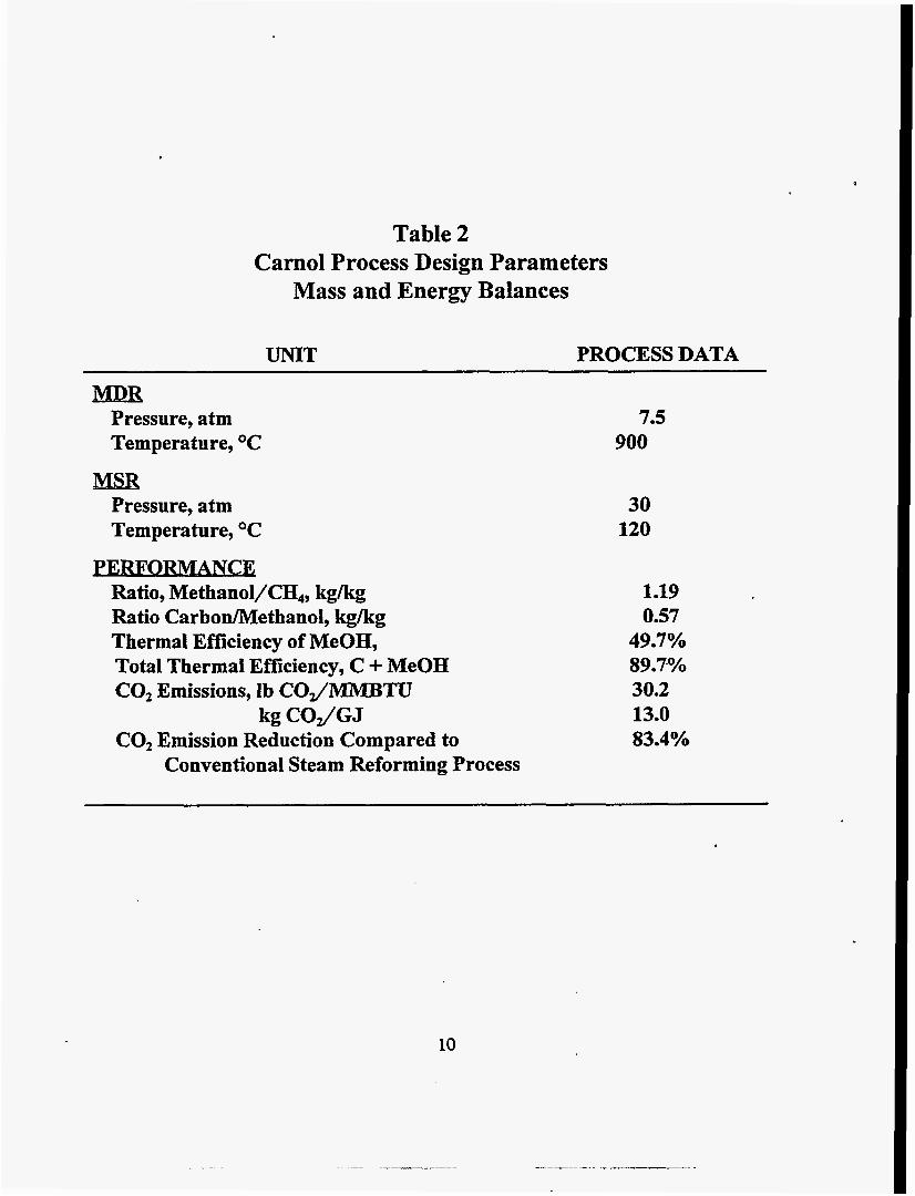
Table 2 Carnol Process Design Parameters
Mass and Energy Balances
UNIT PROCESS DATA
MQR Pressure, atm Temperature, OC
MSR Pressure, atm Temperature, O C
PERFORMANCE Ratio, Methanol/CH,, kgkg Ratio CarbodMethanol, kgkg Thermal Efficiency of MeOH, Total Thermal Efficiency, C + MeOH CO, Emissions, Ib CO/MMBTU
C02 Emission Reduction Compared to kg COJGJ
Conventional Steam Reforming Process
7.5 900
30 120
1.19 0.57
49.7% 89.7% 30.2 13.0 83.4%

(3
11
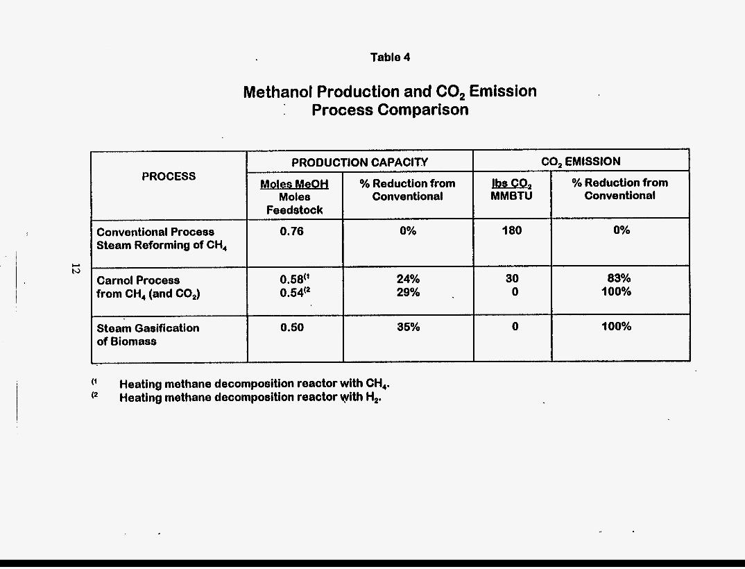
Table 4
- % Reduction from Moles Conventional
Feedstock
Methanol Production and C02 Emission Process Comparison
-2 MMBTU
Carnol Process 24% from CH, (and CO,) 29%
Steam Gasification 0.50 35% of Biomass
PROCESS
30 0
0
Conventional Process Steam Reforming of CH,
0.76 0% 180
0.68(’ 0.54(2
Heating methane decomposition reactor with CH,. Heating methane decomposition reactor yvith H,.
- % Reduction from
Conventional
0%
83% 100%
100%
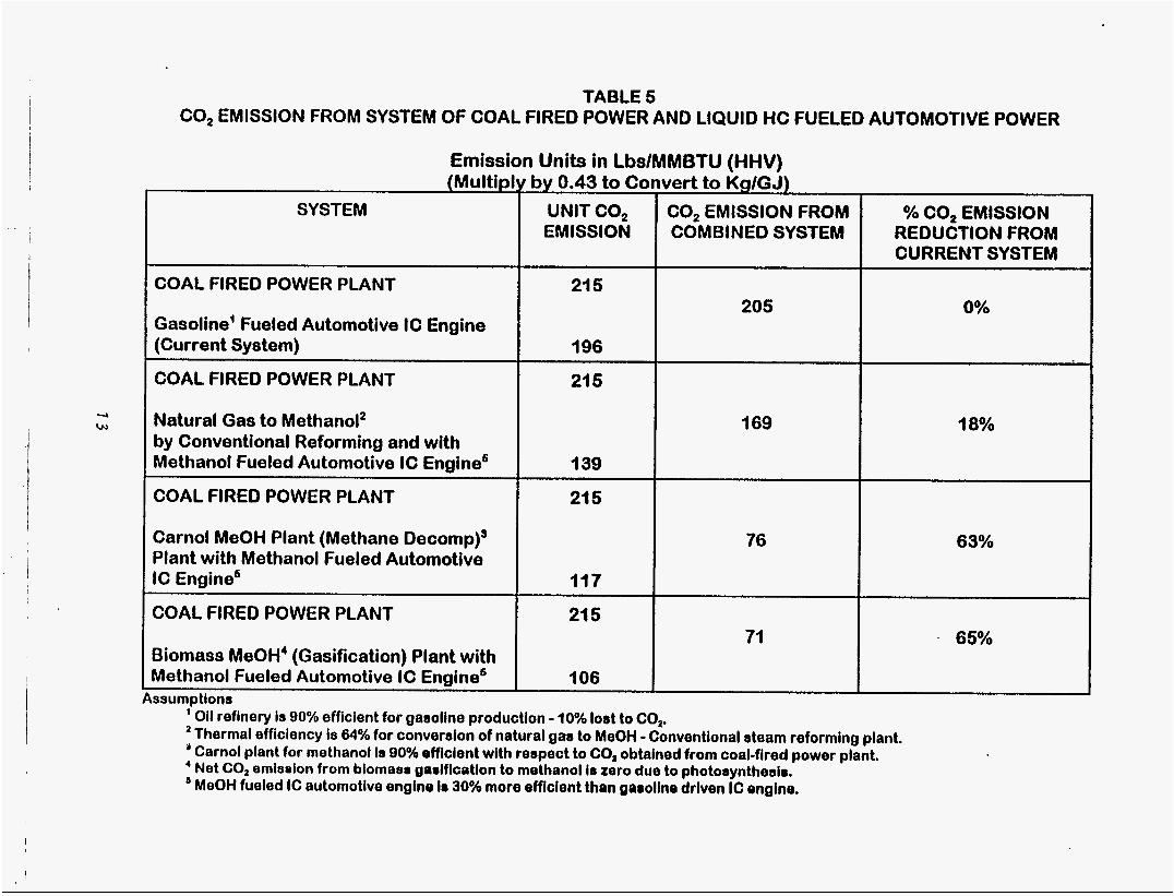
TABLE 5 CO, EMISSION FROM SYSTEM OF COAL FIRED POWER AND LIQUID HC FUELED AUTOMOTIVE POWER
Emission Units in LbslMMBTU (HHV) (Multipl
SYSTEM
COAL FIRED POWER PLANT
Gasoline' Fueled Automotive IC Engine (Current System)
COAL FIRED POWER PLANT
Natural Gas to Methanol2 by Conventional Reforming and with Methanol Fueled Automotive IC Engine6
COAL FIRED POWER PLANT
Carnol MeOH Plant (Methane Decomp)' Plant with Methanol Fueled Automotive IC Engine6
COAL FIRED POWER PLANT
Biomass MeOH' (Gasification) Plant with Methanol Fueled Automotive IC Encline'
by 0.43 to Co UNIT CO, EMISSION
21 5
196
21 5
139
21 5
117
21 5
106
vert to Kgmj) CO, EMISSION FROM COMBINED SYSTEM
205
169
76
Yo CO, EMISSION REDUCTION FROM CURRENT SYSTEM
0%
18%
63%
65%
ssumptions ' Oil refinery is 90% efficient for gasoline production - 10% lost to CO,. ' Thermal efficiency is 64% for converaion of natural gas to MeOH - Conventional steam reforming plant.
' Net CO, emiselon from biomass gadflcatlon to methanol is zero due to photosynthesim. ' MeOH fueled IC automotive engine lo 30% more efficient than gaoollne driven IC engine.
Carnol plant for methanol is 90% efflclent with respect to CO, obtained from coal-fired power plant.
i