Embed Size (px)
Citation preview
BUILDING REGULATION AND ENERGY EFFICIENCY IN TIMBER FRAME HOUSING.
Malcolm Bell and Philip Overend Centre for the Built Environment, Leeds Metropolitan University, UK
Paper given at the RICS COBRA conference at Glasgow Caledonian University 3-5 September 2001. Proceedings published by the RICS Foundation.
Citation:
Bell, M. & Overend, P. (2001) Building regulation and energy efficiency in timber frame housing. In COBRA 2001 Proc. Of the RICS Foundation Construction and Building Research Conference. Edited by John Kelly and Kirsty Hunter, Glasgow Caledonian University, 3-5 September 2001, London, Royal Institution of Chartered Surveyors.
BUILDING REGULATION AND ENERGY EFFICIENCY IN TIMBER FRAME HOUSING.
Malcolm Bell and Philip Overend Centre for the Built Environment, Leeds Metropolitan University, UK
ABSTRACT This paper presents empirical evidence which suggests that the insulation performance of timber frame housing in the UK is often significantly less than the nominal performance assumed by designers and building control authorities. Lowe and Bell (1998) have argued (based on evidence for the USA, ASHRAE, 1993) that UK practice significantly underestimates the proportion of timber (an important thermal bridge) when calculating the U value of many timber frame walls. Despite observations in the USA that timber proportions of 25% are common, UK practice often assumes figures as low as 6% or 7% (DoE & Welsh Office, 1994) with a resulting increase in U value of over 30%. This paper reports the results of a detailed survey of timber frame houses on two sites in the North of England. The results indicate that, if anything, UK practice results in timber proportions higher than in the USA with some walls having a proportion of almost 40%. As insulation standards improve in response to the need to combat climate change, these results take on increasing significance. The implications of these findings for the formulation of regulation and the design of timber frame housing are also discussed. Key words: Timber frame, Building regulation, Energy efficiency, Sustainability, U value. INTRODUCTION In insulated timber framed walls the various framing elements (studs, head and sole plates and the like) result in significant thermal bridging. Although methods that take such bridging into account in heat loss calculations have been available for well over 30 years, it was not until 1995 that building regulations in the UK began to address the problem. Since 1995, the Approved Document to Part L of the Regulations (AD-L, DoE & Welsh Office, 1994) has specified the use of the proportional areas method for the calculation of thermal transmittance (U value). In the latest revision to part L (DETR 2001), which is expected to come into force early in 2002, the Combined Areas Method is specified1. Both methods seek to estimate the U value of an element based on a weighted average of the thermal resistance provided by the different
1 The Proportional Areas and Combined Areas methods are both described in the Chartered Institute of Building Services Engineers design guidance (CIBSE, 1999). The methods are broadly similar but the Combined Areas Method (BS EN ISO 6946: 1996) is now the preferred international standard. In this paper we focus on the type of thermal bridging (quasi- homogeneous) that these two methods are designed to address. However, it is recognised that other forms of thermal bridge exist which are not addressed at all in existing and proposed UK regulations. For a discussion of these other bridging issues in the context of regulation see Lowe and Bell 1998 & 2000. See also Bell and Lowe, 2000 & 2001.
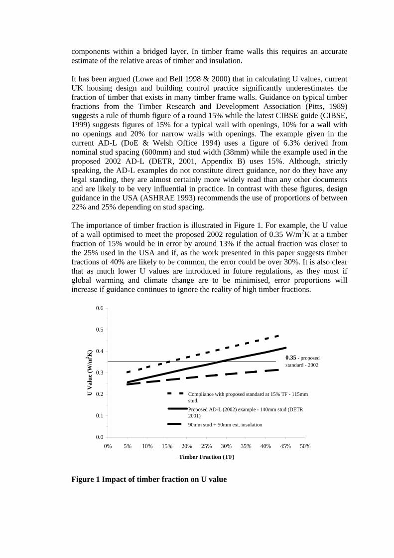
components within a bridged layer. In timber frame walls this requires an accurate estimate of the relative areas of timber and insulation. It has been argued (Lowe and Bell 1998 & 2000) that in calculating U values, current UK housing design and building control practice significantly underestimates the fraction of timber that exists in many timber frame walls. Guidance on typical timber fractions from the Timber Research and Development Association (Pitts, 1989) suggests a rule of thumb figure of a round 15% while the latest CIBSE guide (CIBSE, 1999) suggests figures of 15% for a typical wall with openings, 10% for a wall with no openings and 20% for narrow walls with openings. The example given in the current AD-L (DoE & Welsh Office 1994) uses a figure of 6.3% derived from nominal stud spacing (600mm) and stud width (38mm) while the example used in the proposed 2002 AD-L (DETR, 2001, Appendix B) uses 15%. Although, strictly speaking, the AD-L examples do not constitute direct guidance, nor do they have any legal standing, they are almost certainly more widely read than any other documents and are likely to be very influential in practice. In contrast with these figures, design guidance in the USA (ASHRAE 1993) recommends the use of proportions of between 22% and 25% depending on stud spacing. The importance of timber fraction is illustrated in Figure 1. For example, the U value of a wall optimised to meet the proposed 2002 regulation of 0.35 W/m2K at a timber fraction of 15% would be in error by around 13% if the actual fraction was closer to the 25% used in the USA and if, as the work presented in this paper suggests timber fractions of 40% are likely to be common, the error could be over 30%. It is also clear that as much lower U values are introduced in future regulations, as they must if global warming and climate change are to be minimised, error proportions will increase if guidance continues to ignore the reality of high timber fractions.
0.0
0.1
0.2
0.3
0.4
0.5
0.6
0% 5% 10% 15% 20% 25% 30% 35% 40% 45% 50%
Timber Fraction (TF)
U V
alue
(W/m
2 K)
Compliance with proposed standard at 15% TF - 115mmstud.
Proposed AD-L (2002) example - 140mm stud (DETR2001)
90mm stud + 50mm ext. insulation
0.35 - proposed standard - 2002
Figure 1 Impact of timber fraction on U value
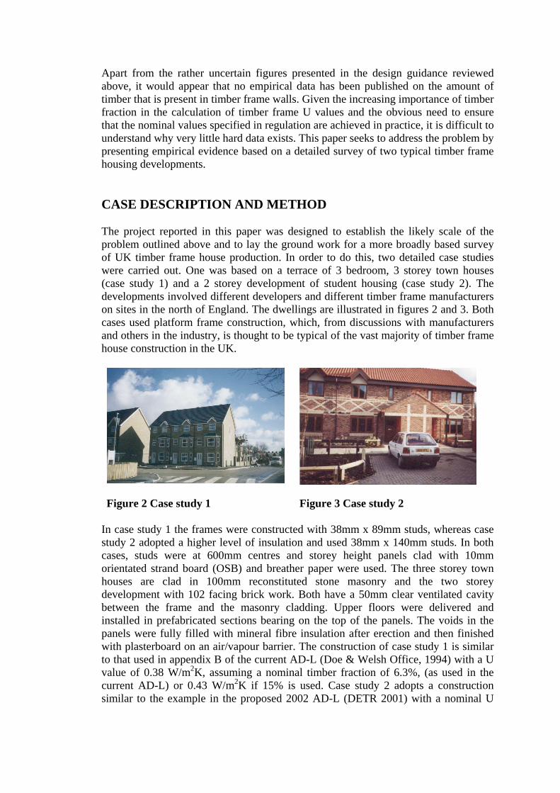
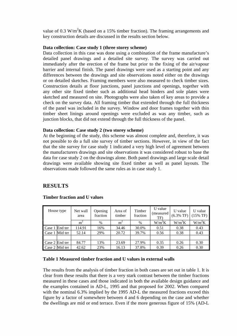
Apart from the rather uncertain figures presented in the design guidance reviewed above, it would appear that no empirical data has been published on the amount of timber that is present in timber frame walls. Given the increasing importance of timber fraction in the calculation of timber frame U values and the obvious need to ensure that the nominal values specified in regulation are achieved in practice, it is difficult to understand why very little hard data exists. This paper seeks to address the problem by presenting empirical evidence based on a detailed survey of two typical timber frame housing developments. CASE DESCRIPTION AND METHOD The project reported in this paper was designed to establish the likely scale of the problem outlined above and to lay the ground work for a more broadly based survey of UK timber frame house production. In order to do this, two detailed case studies were carried out. One was based on a terrace of 3 bedroom, 3 storey town houses (case study 1) and a 2 storey development of student housing (case study 2). The developments involved different developers and different timber frame manufacturers on sites in the north of England. The dwellings are illustrated in figures 2 and 3. Both cases used platform frame construction, which, from discussions with manufacturers and others in the industry, is thought to be typical of the vast majority of timber frame house construction in the UK.
Figure 2 Case study 1 Figure 3 Case study 2 In case study 1 the frames were constructed with 38mm x 89mm studs, whereas case study 2 adopted a higher level of insulation and used 38mm x 140mm studs. In both cases, studs were at 600mm centres and storey height panels clad with 10mm orientated strand board (OSB) and breather paper were used. The three storey town houses are clad in 100mm reconstituted stone masonry and the two storey development with 102 facing brick work. Both have a 50mm clear ventilated cavity between the frame and the masonry cladding. Upper floors were delivered and installed in prefabricated sections bearing on the top of the panels. The voids in the panels were fully filled with mineral fibre insulation after erection and then finished with plasterboard on an air/vapour barrier. The construction of case study 1 is similar to that used in appendix B of the current AD-L (Doe & Welsh Office, 1994) with a U value of 0.38 W/m2K, assuming a nominal timber fraction of 6.3%, (as used in the current AD-L) or 0.43 W/m2K if 15% is used. Case study 2 adopts a construction similar to the example in the proposed 2002 AD-L (DETR 2001) with a nominal U
value of 0.3 W/m2K (based on a 15% timber fraction). The framing arrangements and key construction details are discussed in the results section below. Data collection: Case study 1 (three storey scheme) Data collection in this case was done using a combination of the frame manufacture’s detailed panel drawings and a detailed site survey. The survey was carried out immediately after the erection of the frame but prior to the fixing of the air/vapour barrier and internal finish. The panel drawings were used as a starting point and any differences between the drawings and site observations noted either on the drawings or on detailed sketches. Framing members were also measured to check timber sizes. Construction details at floor junctions, panel junctions and openings, together with any other site fixed timber such as additional head binders and sole plates were sketched and measured on site. Photographs were also taken of key areas to provide a check on the survey data. All framing timber that extended through the full thickness of the panel was included in the survey. Window and door frames together with thin timber sheet linings around openings were excluded as was any timber, such as junction blocks, that did not extend through the full thickness of the panel. Data collection: Case study 2 (two storey scheme) At the beginning of the study, this scheme was almost complete and, therefore, it was not possible to do a full site survey of timber sections. However, in view of the fact that the site survey for case study 1 indicated a very high level of agreement between the manufacturers drawings and site observations it was considered robust to base the data for case study 2 on the drawings alone. Both panel drawings and large scale detail drawings were available showing site fixed timber as well as panel layouts. The observations made followed the same rules as in case study 1. RESULTS Timber fraction and U values
Net wall area
Opening fraction
Area of timber
Timber fraction
U value (measured
TF)
U value (6.3% TF)
U value (15% TF)
House type
m2 % m2 % W/m2K W/m2K W/m2K Case 1 End ter 114.91 16% 34.46 30.0% 0.51 0.38 0.43 Case 1 Mid ter 52.14 29% 20.72 39.7% 0.56 0.38 0.43
Case 2 End ter 84.77 13% 23.69 27.9% 0.35 0.26 0.30 Case 2 Mid ter 42.62 23% 16.13 37.8% 0.39 0.26 0.30
Table 1 Measured timber fraction and U values in external walls The results from the analysis of timber fraction in both cases are set out in table 1. It is clear from these results that there is a very stark contrast between the timber fractions measured in these cases and those indicated in both the available design guidance and the examples contained in AD-L, 1995 and that proposed for 2002. When compared with the nominal 6.3% implied by the 1995 AD-L the measured fractions exceed this figure by a factor of somewhere between 4 and 6 depending on the case and whether the dwellings are mid or end terrace. Even if the more generous figure of 15% (AD-L
2002, CIBSE,1999) is used as a starting point, the difference in timber fraction is very large (an increase of 86% to 165%). It is also worth pointing out that, despite the difference in dwelling design the two cases display very similar timber fractions and a comparison of the panel drawings for each scheme show a high degree of similarity in the construction of individual panels. The difference between end-terrace and mid-terrace forms (some 10 percentage points) is largely a function of the high proportion of opening area in the mid-terrace dwellings. This is so because openings not only add to the amount of framing timber but also reduce the opaque wall area. The impact on U value of the much higher timber fraction in these dwellings is clear from table 1 with increases of between 33% and 18% for the end-terrace type, depending on the base timber fraction used (6.3% and 15% respectively), and between 48% and 30% for the mid-terrace type. What is more, if the observed timber fractions were used instead of the nominal values, the wall U value in case 1 would not comply with the requirements of the Elemental Method, specified in AD-L 19952. Modelling of the end and mid-terrace house types from case study 1 suggest that the effect of the higher U values would be to increase estimates of whole house space heating energy consumption (under standard conditions) by about 12% compared with a U value based on a 6.3% timber fraction and by 7% if a U value based on 15% were used. Sources of timber Table 2 sets out the different sources of timber framing. The data in table 2 clearly demonstrate the inappropriateness of the view, as implied in AD-L 1995, that timber fraction is a reflection of stud width and stud spacing. In practice, head and sole plates, timber around openings and floor junctions are just as important, sometimes more so. The balance of importance varies, depending on the house form and the detailed design of the panels. For example the timber fraction in mid-terrace forms seems to be strongly influenced by framing timber at openings and the influence of the floor junction is stronger in the three storey case than in the two storey case.
Case study 1 Case study 2 End terrace Mid terrace End terrace Mid terrace
Area Percentage of NPA Area Percentage
of NPA Area Percentage of NPA Area Percentage
of NPA
Framing element m2 % m2 % m2 % m2 % Studs 9.47 8.2 4.16 8.0 8.85 10.4 5.49 12.9 Sole & Head plates 6.87 6.0 3.53 6.8 5.37 6.3 3.05 7.2 Timber at openings 9.14 8.0 8.45 16.2 5.52 6.5 5.35 12.6 Floor junction 8.99 7.8 4.59 8.8 3.95 4.7 2.2 5.3 Total 34.46 30.0 20.72 39.7 23.69 27.9 16.13 37.8 Net panel area (NPA. m2) 114.91 52.14 84.77 42.62 Table 2 Sources of timber A qualitative assessment of the two cases indicates that the high timber fraction is the result of the need for the panel design to satisfy a wide range of requirements. These include structural integrity, ease of manufacture, ease of transportation, ease of erection and the need to provide a fixing for standard sheet materials such as
2 This does not mean that the dwellings as a whole do not comply, since SAP calculations indicate that they would satisfy the requirements of the Target U Value and Energy Rating Methods.
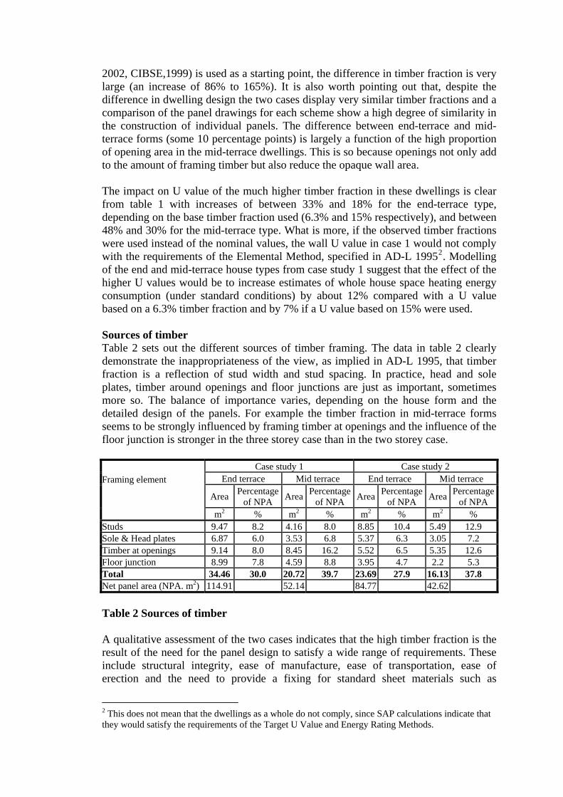
plasterboard. However, as discussed in the next section, the assessment also suggests that there has been little attempt on the part of frame designers to minimise the amount of timber used or to avoid details that create large areas of through timber. Figure 3 shows the layout of one of the panels observed in case study 1. This illustrates the extent of additional framing around openings. The need to strengthen the lintel support at jambs results in additional studs with a shortened (cripple) stud supporting the lintel and sill frame. This results in at least a double stud for most of the panel height and a triple stud up to sill level. Where openings are large (as in figure 3) triple and quadruple studs are often used. Observations of panel layouts in both cases revealed a tendency for no account to be taken of the timber around openings in positioning the next “normal” stud. The full height stud between window openings in figure 3 illustrates this point. Since the distance between the openings is less than 600mm the stud could be omitted without loss of structural integrity or problems fixing the internal plaster board finish.
Soleplate Cripple stud Trimming
TrimmingLintel
Full height stud
Headplate
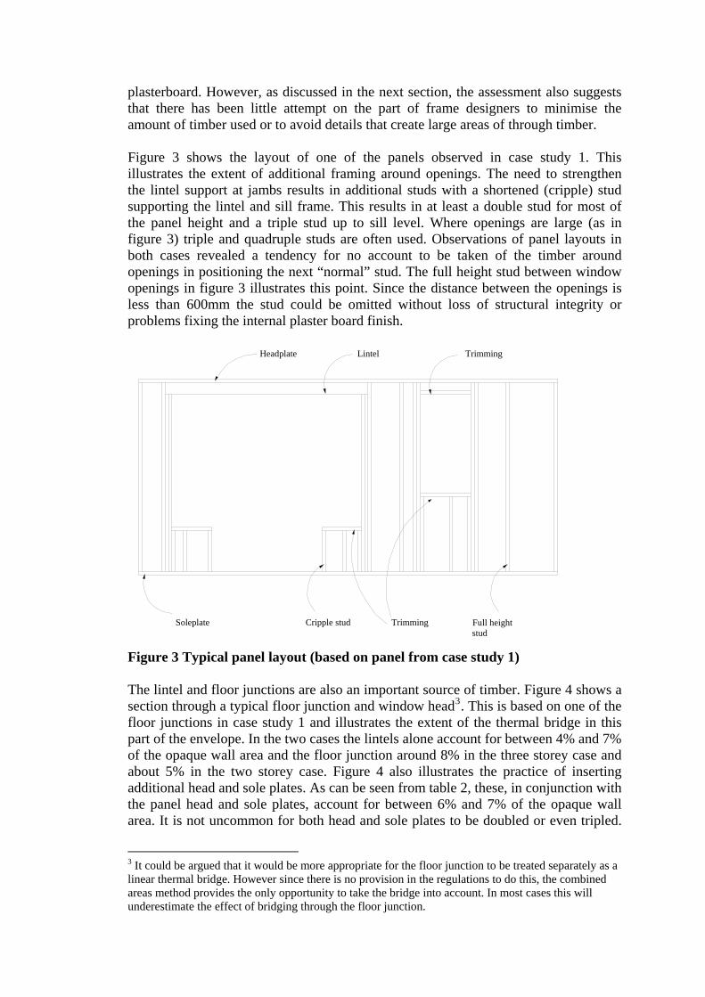
Figure 3 Typical panel layout (based on panel from case study 1) The lintel and floor junctions are also an important source of timber. Figure 4 shows a section through a typical floor junction and window head3. This is based on one of the floor junctions in case study 1 and illustrates the extent of the thermal bridge in this part of the envelope. In the two cases the lintels alone account for between 4% and 7% of the opaque wall area and the floor junction around 8% in the three storey case and about 5% in the two storey case. Figure 4 also illustrates the practice of inserting additional head and sole plates. As can be seen from table 2, these, in conjunction with the panel head and sole plates, account for between 6% and 7% of the opaque wall area. It is not uncommon for both head and sole plates to be doubled or even tripled.
3 It could be argued that it would be more appropriate for the floor junction to be treated separately as a linear thermal bridge. However since there is no provision in the regulations to do this, the combined areas method provides the only opportunity to take the bridge into account. In most cases this will underestimate the effect of bridging through the floor junction.
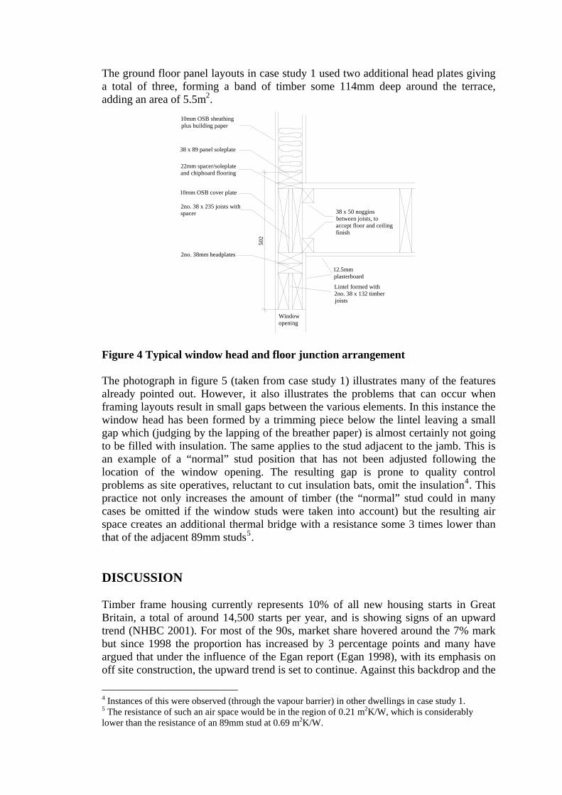
The ground floor panel layouts in case study 1 used two additional head plates giving a total of three, forming a band of timber some 114mm deep around the terrace, adding an area of 5.5m2.
2no. 38mm headplates
2no. 38 x 235 joists with spacer 38 x 50 noggins
between joists, to accept floor and ceiling finish
22mm spacer/soleplate and chipboard flooring
38 x 89 panel soleplate
10mm OSB sheathing plus building paper
12.5mm plasterboard
10mm OSB cover plate
Lintel formed with 2no. 38 x 132 timber joists
502
Window opening
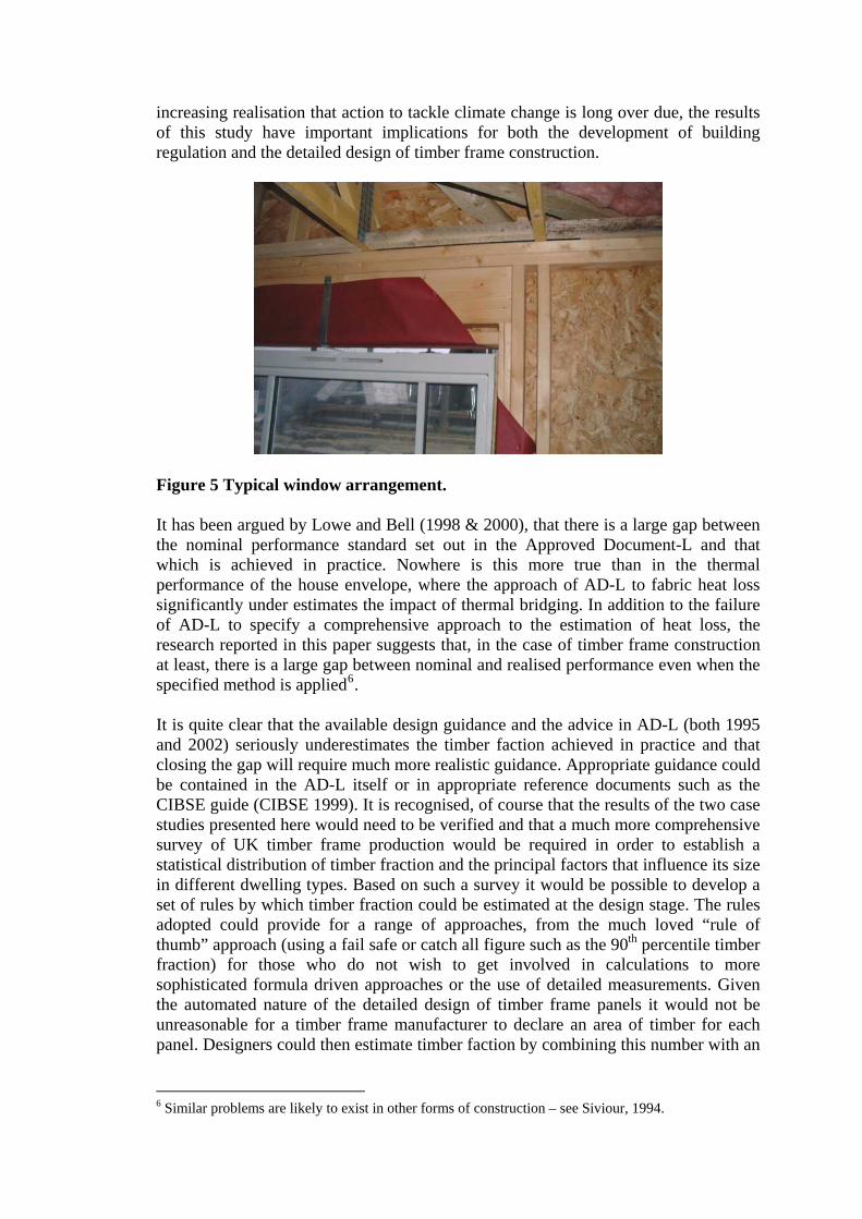
Figure 4 Typical window head and floor junction arrangement The photograph in figure 5 (taken from case study 1) illustrates many of the features already pointed out. However, it also illustrates the problems that can occur when framing layouts result in small gaps between the various elements. In this instance the window head has been formed by a trimming piece below the lintel leaving a small gap which (judging by the lapping of the breather paper) is almost certainly not going to be filled with insulation. The same applies to the stud adjacent to the jamb. This is an example of a “normal” stud position that has not been adjusted following the location of the window opening. The resulting gap is prone to quality control problems as site operatives, reluctant to cut insulation bats, omit the insulation4. This practice not only increases the amount of timber (the “normal” stud could in many cases be omitted if the window studs were taken into account) but the resulting air space creates an additional thermal bridge with a resistance some 3 times lower than that of the adjacent 89mm studs5. DISCUSSION Timber frame housing currently represents 10% of all new housing starts in Great Britain, a total of around 14,500 starts per year, and is showing signs of an upward trend (NHBC 2001). For most of the 90s, market share hovered around the 7% mark but since 1998 the proportion has increased by 3 percentage points and many have argued that under the influence of the Egan report (Egan 1998), with its emphasis on off site construction, the upward trend is set to continue. Against this backdrop and the
4 Instances of this were observed (through the vapour barrier) in other dwellings in case study 1. 5 The resistance of such an air space would be in the region of 0.21 m2K/W, which is considerably lower than the resistance of an 89mm stud at 0.69 m2K/W.
increasing realisation that action to tackle climate change is long over due, the results of this study have important implications for both the development of building regulation and the detailed design of timber frame construction.
Figure 5 Typical window arrangement. It has been argued by Lowe and Bell (1998 & 2000), that there is a large gap between the nominal performance standard set out in the Approved Document-L and that which is achieved in practice. Nowhere is this more true than in the thermal performance of the house envelope, where the approach of AD-L to fabric heat loss significantly under estimates the impact of thermal bridging. In addition to the failure of AD-L to specify a comprehensive approach to the estimation of heat loss, the research reported in this paper suggests that, in the case of timber frame construction at least, there is a large gap between nominal and realised performance even when the specified method is applied6. It is quite clear that the available design guidance and the advice in AD-L (both 1995 and 2002) seriously underestimates the timber faction achieved in practice and that closing the gap will require much more realistic guidance. Appropriate guidance could be contained in the AD-L itself or in appropriate reference documents such as the CIBSE guide (CIBSE 1999). It is recognised, of course that the results of the two case studies presented here would need to be verified and that a much more comprehensive survey of UK timber frame production would be required in order to establish a statistical distribution of timber fraction and the principal factors that influence its size in different dwelling types. Based on such a survey it would be possible to develop a set of rules by which timber fraction could be estimated at the design stage. The rules adopted could provide for a range of approaches, from the much loved “rule of thumb” approach (using a fail safe or catch all figure such as the 90th percentile timber fraction) for those who do not wish to get involved in calculations to more sophisticated formula driven approaches or the use of detailed measurements. Given the automated nature of the detailed design of timber frame panels it would not be unreasonable for a timber frame manufacturer to declare an area of timber for each panel. Designers could then estimate timber faction by combining this number with an
6 Similar problems are likely to exist in other forms of construction – see Siviour, 1994.
assessment of bridging through additional head and sole plates and floor junctions. Such an approach could take the form7:
A
dlPTFn
iii
n
kk ∑∑
==
×+=11
)( (1)
Where: = Timber Fraction, TFkP = area of through timber in panel k ,
il = length of the exposed perimeter at level i (measured on the internal face)8,
id = depth of through timber at level i,
A = area of opaque wall surface (measured on the internal face). The decision as to how timber fraction should be estimated is, however, of less importance than the recognition by the DETR and the industry that a problem exists and that much more robust guidance, based on sound empirical data, is required. The adoption of a more realistic approach to thermal bridging in timber frame construction has important implications for design and manufacture. More robust regulation would mean that manufacturers would no longer be able to ignore thermal performance. The observations of panel design made for this study suggest that much could be done to optimise the arrangement of timber framing within panels. Such an approach would seek to relate window and door openings to the 600mm stud spacing module, minimise the use of additional head and sole plates and redesign floor junctions to ensure that the structure did not penetrate the insulation layer. This would, of course, require timber frame houses to be designed based on the optimisation of the timber frame, not the external brick skin. Too often, it would seem, timber frame manufacturers are required to base their designs on masonry house types set out to suit a masonry module. Indeed, the house type studied in case study 1 was a masonry design built in both timber frame and masonry on the same site. Discussions with one of the timber frame manufacturers indicated that this was by no means uncommon. Although much can be done to reduce timber fractions in this type of timber frame construction, it is unlikely that fractions could be reduced below 20%, particularly when the opening ratio is high. As U value thresholds are reduced, it will become much more difficult to avoid a fundamental redesign of the construction itself. In the short to medium term it may be feasible for the industry to respond to the proposed 2002 AD-L (DETR 2001) by increasing stud depth to 140mm (see in AD-L 2002, appendix B) but as U values fall further other changes would be required ranging from the application of external sheathing insulation to the adoption of timber I beam technology. The former approach would minimise change and, as illustrated in figure 1, is less influenced by variations in timber fraction. However the higher embodied energy content of suitable external insulation products would reduce overall sustainability. The use of I beam technology, on the other hand, has the advantage of minimising thermal bridging, while at the same time reducing timber volume, particularly as insulation thickness increases. This technology has been used in a small
7 An alternative approach based on the different sources of timber has been developed based on the case study dwellings (Overend 2001) but if information on panel design is available from a manufacturer the model presented in this paper is likely to be more accurate and easier to use. 8 Level includes timber such as head and sole plates at ground floor and roof levels as well as intermediate floor zones.
number of low energy houses in the UK (Olivier and Willoughby, 1996a & 1996b) and is common in parts of Europe and North America. Given the urgent need to address the problems of climate change a fundamental rethink of how we construct our dwellings is inevitable and the timber frame industry needs to address the problems raised in this paper sooner rather than later. CONCLUDING COMMENTS Although, based as it is on two cases, this study is limited, it is becoming clear that domestic timber frame construction in the UK may have a much higher timber fraction than that which is stated in design guidance and acknowledged in both the current and proposed Building Regulations Approved Document L (DOE & Welsh Office, 1994 & DETR, 2001). A comprehensive study of UK timber frame production would, of course, be required to establish the full extent of the problem. It is crucial, however, that such a study is based on direct observation using a straightforward, robust and repeatable method. If the results reported here are confirmed, they will have far reaching implications for the formulation of regulation and the design and development of energy efficient timber frame housing in the UK. REFERENCES ASHRAE (1993) ASHRAE Handbook 1993: Fundamentals. SI edition. American
Society of Heating, Refrigeration and Air Conditioning Engineers, Georgia, USA. Bell, M. and Lowe, R.J. (2001) Building regulation and sustainable housing Part 3:
Setting and implementing standards, Structural Survey. Vol. 19 no. 1. Bell, M. and Lowe, R.J. (2000) Building regulation and sustainable housing Part 1: a
critique of Part L of the Building Regulations 1995 for England and Wales. Structural Survey, Vol. 18, no.1, pp. 28 to 37.
BS EN ISO 6946: 1996 Building elements and building elements - Thermal resistance and thermal transmittance (U value) - Calculation method. British Standards Institution.
CIBSE (1999) Environmental design: CIBSE Guide A, Chartered Institution of Building Services Engineers, London, UK.
DETR (2001) The Building Regulations; 2000 Interim Draft Approved Document L: Conservation of Fuel and Power, Department of the Environment, Transport and the Regions, London, UK.
DoE. & Welsh Office (1994) The Building Regulations; 1991 Approved Document L (1995): Conservation of Fuel and Power, The Stationary Office, London.
Egan, J. (1998) Rethinking Construction, Department of the Environment, Transport and the Regions, London, UK.
Lowe, R. J. and Bell, M. (1998) Towards Sustainable Housing: building regulation for the 21st century. A report prepared for the Joseph Rowntree Foundation. Leeds Metropolitan University/ Joseph Rowntree Foundation, Leeds.
Lowe, R.J and Bell, M. (2000) Building regulation and sustainable housing Part 2: Technical issues. Structural Survey, Vol. 18, no.2, pp. 77 to 88.
NHBC (2001) New House-Building Statistics, National House-Building Council, Amersham, UK.
Olivier, D. & Willoughby, J. (1996a) Review of Ultra-low-energy Homes: A Series of UK and Overseas Profiles. BRECSU, General Information Report 38, Building Research Establishment, Watford, UK.
Olivier, D. & Willoughby, J. (1996b) Review of Ultra-low-energy Homes: Ten UK Profiles in Detail. BRECSU, General Information Report 39, Building Research Establishment, Watford, UK.
Overend, P. (2001) Thermal Bridging in timber frame walls, Building Surveying dissertation, Leeds Metropolitan University, Leeds, UK.
Pitts, G. (1989) Energy Efficient Housing – A Timber Frame Approach, Timber Research and Development Association, High Wycombe, UK.
Siviour, J.B. (1994) Experimental U-Values of Some House Walls, Building Services Engineering Research and Technology, Vol 15 (1).
ACKNOWLEDGEMENTS We would like to acknowledge the help and support of the housing developers and the timber frame manufacturers in providing access to the site and to the design documentation required for this study. We would particularly like to thank the site staff for their forbearance and help.