Embed Size (px)
Citation preview
SUMMARYIn the autumn of 1902 the Wright brothers spent just over eight weeksat their test site in the Kill Devil Hills near Kitty Hawk, NorthCarolina, testing their third Glider design. During the trial period theyimplemented an inter-linked roll-yaw control system. Together withthe forward canard surface, this gave them control over vertical andhorizontal components of the flight path. They were also able to honeand perfect their piloting skills. In just two days in the final week, theymade about 250 glides. The success of the trials instilled the confi-dence in the Wright brothers to proceed rapidly to the construction ofa powered aircraft. Within a month of returning to Dayton, they werewriting to engine manufacturers with their specification – an enginethat would develop eight to nine brake horse power, weigh no morethan 180lb and be free from vibration; they would not find a suitablepowerplant and had to design and build their own. The invention ofthe powered aeroplane in 1903 somewhat overshadows the earlier crit-ical flight control developments, but the birth of flight control in 1902opened the way for aviation to flourish. With the aid of modern flightscience techniques – wind-tunnel testing, computational flight dynam-ics and piloted simulation, this paper examines the technology of theWrights’ 1902 glider. The research forms a part of the LiverpoolWright Project, aiming to bring to life the Wright brothers’ achieve-ments in this centenary period. Wilbur and Orville Wright are recog-nised by many as the first aeronautical engineers and test pilots. In somany ways they set standards that today’s engineers and organisationsbenefit from. Their work in the period 1901 to 1902 reflects theirgenius and the paper reviews this work in detail, examining the design,aerodynamic characteristics and flying qualities of the aircraft that firstfeatured a practical three-axis control system.
NOMENCLATUREA system matrixAR aspect ratio (span2/wing area)b wing spanB control matrixc wing chordCD drag coefficientCl rolling moment coefficientCL lift coefficientCM pitching moment coefficientCn yawing moment coefficientg gravitational accelerationHn static marginIxx, Iyy, Izz moments of inertia about body axesk (Smeaton) coefficient of air pressureKθ, Kφ, Kψ pilot gainsKp pilot transfer function between error and controlp, q, r perturbation angular velocities about body axesRe Reynolds number (ρVc/µ)S wing areaTθ1, Tθ2 time constants of closed-loop zeros TD time to double amplitudeTs spiral mode time constantTSP1, TSP2 time constants of ‘short period’ modeu control vectorUe trim (equilibrium) speed component along x axisu,v,w perturbation velocities along body axesV flight velocityXu, Mw aerodynamic derivatives
THE AERONAUTICAL JOURNAL DECEMBER 2003 697
Paper No. 2854. Manuscript received 22 August 2003 accepted 29 September 2003.
The birth of flight control: An engineering analysis of the Wright brothers’1902 glider
G. D. PadfieldProfessor of Aerospace EngineeringB. LawrenceResearch student
Department of EngineeringThe University of LiverpoolLiverpool, UK
x state vectorYδc transfer function between canard and pitch attitudeα angle of incidence (attack)β angle of sideslipδc canard angle (positive pitch up)δw warp angle (positive roll left) = incidence right tip –
incidence left tipδr rudder angle (positive nose right)ζp, ωp damping ratio and frequency of phugoidζd, ωd damping ratio and frequency of Dutch roll µ coefficient of viscosityρ air densityθ, φ, ψ Euler attitudesθe, θd pitch attitude error and demandλ eigenvalue
rate of change of rolling moment coefficient with warp angle
rate of change of yawing moment coefficient with rudder angle
1.0 INTRODUCTIONThe Wright brothers had intended their flights on 17 December 1903to be a private matter and had no intention of making a detailedpublic statement. However, since, as Wilbur wrote, “the contents ofa private telegram, announcing to our folks at home the success ofour trials, was dishonestly communicated to the newspapers,” theyfelt the need to put the record straight(1). Wilbur’s statement to theAssociated Press, written on 5 January 1904, ended thus,
“...... we were determined, before returning home, to knowwhether the machine possessed sufficient power to fly, sufficientstrength to withstand the shocks of landings, and sufficient capac-ity of control to make flight safe in boisterous winds, as well as incalm air. When these points had been definitely established, we atonce packed our goods and returned home, knowing that the ageof the flying machine had come at last.”
In this brief and reluctant communication to the world, Wilburrevealed the purposeful intentions of their aeronautical endeavours,emphasising performance, structural strength and control as the com-bined objectives of the world’s first successful flight test of a
powered aeroplane. The following two years were to prove that theWrights had much more development work to do to arrive at a prac-tical aeroplane†, but the fundamental challenge of flight control hadbeen solved through research and development over the two yearsleading up to December 1903. The critical breakthrough came in theautumn of 1902.
On the night of 23 October 1902, Orville Wright wrote to his sisterKatharine from their camp at the Kill Devil Hills near Kitty Hawk,North Carolina(1).
“The past five days have been the most satisfactory for glidingthat we have had. In two days we made over 250 glides, or morethan we had made all together up to the time Lorin left. We havegained considerable proficiency in the handling of the machinenow, so that we are able to take it out in any kind of weather. Daybefore yesterday we had a wind of 16 meters per second or about 30miles an hour, and glided in it without any trouble. That was thehighest wind a gliding machine was ever in, so that we now hold allthe records! The largest machine we handled in any kind ofweather, made the longest distance glide, the longest time in the air,the smallest angle of descent, and the highest wind!!!”
The ‘machine’ that Orville referred to was the Wright brothers’ 1902glider, featuring, for the first time, three-axis control over the motionof the aircraft. The Wrights had flown between 700 and 1,000 flightsin this aircraft during the autumn of 1902. It is testament to the geniusof the Wrights that they had accomplished this achievement workingpart time in about three years.
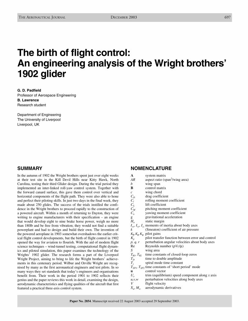
Figure 1 shows one of Orville’s first flights with the three-axiscontrol operational on the 1902 glider. He and Wilbur had “thoughttogether” to arrive at this design innovation. The aircraft weighed119lbf (53kgf) empty, 259lbf (115kgf) with Wilbur on board and264lbf (118kgf) with Orville on board. According to Orville’s diary(1),the longest distance of 622ft was flown by Wilbur in 26 seconds witha glide angle of just over 8 deg. The best glide angle was quoted asabout 6 deg(1) (see Ref. 1, p 266 for flights on 30 September) when thewind was 5ms-1 and speed over ground averaged 23ft/sec††. Thelongest and highest duration glides were made on the north slope ofthe big Kill Devil Hill (max slope 9⋅5°, Ref. 1 p 259) on 23 Octoberwith a glide slope of between 8° and 9°. Over the few weeks at the endof September and into October, the brothers developed and perfectedtheir flying skills. To quote their friend and aeronautical colleague,Octave Chanute(1),
“The two brothers glided alternately and they soon obtainedalmost complete mastery over the inconsistencies of the wind. Theymet the wind gusts and steered as they willed. They did not ventureto sweep much more than one quarter circle, so as not to lose theadvantage of a headwind, but they constantly improved in thecontrol of the machine and in learning the arts of the birds. Some800 glides were made.”
The autumn flight test campaign of 1902 was very successful for theWrights and one is left with the thought that their solution to three-axiscontrol, linking roll and yaw control to mitigate the powerful adverseyaw effects, was one of ‘the’ critical breakthroughs in the history ofaviation and aeronautical engineering. Peter Jakab sums this up in hisbook on the Wrights’ process of invention(3); “If the Wright brothersare to be cited as the inventors of the airplane based on havingresolved all the fundamental problems of mechanical flight then it isnot necessary to look beyond the 1902 glider… what was innovativeabout the (1903) Flyer was present in the earlier 1902 glider..”
This paper records a study of this aircraft and its development, set inthe context of aeronautical knowledge at the turn of the 20th centuryand reflected by the synthesis and analysis conducted in the LiverpoolWright project. Section 2 presents a resume of the Wrights’ work priorto the 1902 tests and Section 3 goes on to interpret the research anddevelopment process undertaken during the winter of 1901-2. Section4 describes the 1902 flights tests and how the three-axis control
698 THE AERONAUTICAL JOURNAL DECEMBER 2003
θ
l
w
C∂∂δ
n
r
C∂∂δ
Figure 1. The Wright brothers glider on 10 October 1902, Orville at thecontrols, Wilbur at the starboard wing, Dan Tate to port.
†On 16 Oct 1905 the Wrights flew their Flyer No 3 for the last time until May 1908; twoweeks before, Orville had flown for 39km in 38 minutes. In the first two weeks ofOctober 1905, the Wrights (Ref. 1, p 517) “..did more flying than in all our previousflights of three years put together.” The first powered aircraft flight in Europe (bySantos Dumont) would not take place until the autumn of 1906 (Ref. 2). ††The Wrights regularly mixed their units as a result of both US and European influences.
solution evolved. In Section 5, the Wrights’ invention is re-visitedwith modern engineering tools including wind tunnel testing, com-putational aerodynamics, flight dynamics analysis and piloted simu-lation. Here, some of the fundamental aspects of the Wrights’approach – the use of the canard, wing warping and the warp-rudderinterlink, wing anhedral and the mastery of control over stability –are explored to reveal the unique nature of their genius. The paper isrounded off with a very brief reflection on the consequent, post-1902, activities of the Wrights in Section 6 and some concludingremarks in Section 7.
2.0 THE WRIGHT BROTHERS AND THEIR PRE-1902 WORK
2.1 Background
Wilbur was born in 1867 and Orville in 1871, the same year thefamily moved into a new house, No 7 Hawthorn Street, in Dayton,Ohio. They had two elder brothers Reuchlin and Lorin, and ayounger sister, Katharine. A clear picture of the kind of life theWright brothers experienced during their upbringing is portrayed inTom Crouch’s thesis on a life of Wilbur and Orville Wright – TheBishop’s Boys(4). Their father, Milton Wright, a minister in theChurch of the United Brethren in Christ, established a ‘corporate’family identity. Crouch describes Milton as “rather uncompromisingand strong principled… inherited from his father and passed to hischildren.” Milton considered that “the world was not a friendly placefor honest men and women, temptations beckoned, unscrupulouspersons lay in wait; friends would fall away in times of trial… andultimately the strength of family bonds offered the only real supportone could hope for in life.” This austerity seems to have been bal-anced by the caring attention of their mother, Susan Catherine(Koerner) Wright. Crouch notes that while no diary survived to showher side of the story, she played a key role in her children’s fascina-tion for engineering. “Her children remember her as having consid-erable mechanical aptitude, having spent time in her father’scarriage shop as a young girl. She designed and built simple house-hold appliances for herself and made toys for her children. When theboys wanted mechanical advice and assistance, they came from theirmother. Milton was one of those men who had difficulty driving anail straight.” Crouch makes the keen observation that, “Wilbur andOrville had their mother to thank for their extraordinary ability tovisualise the operation of mechanisms that had yet to beconstructed.”
Tom Crouch provides us with vivid images of the two inventors;to paraphrase – Wilbur was an outgoing person and a gifted speaker,never rattled in thought or temper; cool, aloof and controlled. He hadstruggled to overcome fits of depression in his young manhood,developing considerable self confidence in the process. He drewfriends from his older brother’s circles. Orville, on the other hand,was especially close to his sister Katharine, almost her protector. Hewas impulsive and excitable, an enthusiast and optimist, on fire withnew inventions. While the airplane was Wilbur’s idea, Orville sup-plied the drive to continue in difficult times. With the family, Orvillewas something of a tease and practical joker, but with strangers hewas painfully shy. He outlived Wilbur by 36 years but refused tospeak in public.
When Wilbur was eleven and Orville seven years old, Miltonbought them a toy helicopter, designed by the Frenchman AlphonsePénaud, who himself had based his design on one of Leonardo daVinci’s aircraft concepts. This made a big impression and the broth-ers went on to construct several models from their own designs. Wesee here the seed of their interest in aviation and it was to be nur-tured over the next 20 years in a variety of ways – their fascinationwith bird flight, following the work of the German engineer and
PADFIELD AND LAWRENCE THE BIRTH OF FLIGHT CONTROL – AN ENGINEERING ANALYSIS OF THE WRIGHT BROTHERS’ 1902 GLIDER 699
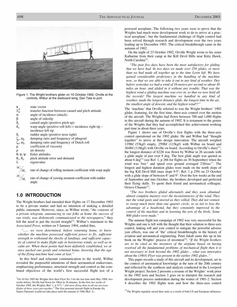
Figure 2. Wilbur and Orville Wright.
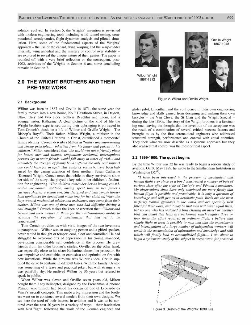
Figure 3. Sketch of the Wrights’ 1899 Kite.
Wilbur Wright1867-1912
Orville Wright1867-1948
glider pilot, Lilienthal, and the confidence in their own engineeringknowledge and skills gained from designing and making their ownbicycles – the Van Cleve, the St Clair and the Wright Special –during the late 1890s. The story of the Wright brothers is a fascinat-ing one, leaving the thought that the invention of the aeroplane wasthe result of a combination of several critical success factors andbrought to us by the first aeronautical engineers who addressedstructural strength, performance and control with equal attention.They took what we now describe as a systems approach but theyalso realised that control was the most critical aspect.
2.2 1899-1900: The quest begins
By the time Wilbur was 32 he was ready to begin a serious study ofaviation. On 30 May 1899, he wrote to the Smithsonian Institution inWashington DC(1).
“I have been interested in the problem of mechanical andhuman flight ever since as a boy I constructed a number of bats ofvarious sizes after the style of Cayley’s and Pénaud’s machines.My observations since have only convinced me more firmly thathuman flight is possible and practicable. It is only a question ofknowledge and skill just as in acrobatic feats. Birds are the mostperfectly trained gymnasts in the world and are specially wellfitted for their work, and it may be that man will never equal them,but no one who has watched a bird chasing an insect or anotherbird can doubt that feats are performed which require three orfour times the effort required in ordinary flight. I believe thatsimple flight at least is possible to man and that the experimentsand investigations of a large number of independent workers willresult in the accumulation of information and knowledge and skillwhich will finally lead to accomplished flight…. I am about tobegin a systematic study of the subject in preparation for practical
work to which I expect to devote what time I can spare from myregular business. I wish to obtain such papers as the SmithsonianInstitution has published on this subject, and if possible a list ofother works in print in the English Language. I am an enthusiast,but not a crank in the sense that I have some pet theories as to theproper construction of a flying machine. I wish to avail myself ofall that is already known and then if possible add my mite to helpon the future worker who will attain final success.”
Wilbur’s request was granted and the Smithsonian sent him a list oftheir publications, which included works by Chanute, Langley andMeans, in addition to a set of Smithsonian pamphlets including onesby Lilienthal and Langley. In the summer of 1899 Wilbur con-structed his first kite with a span of 5ft. He was convinced that themethod of control adopted by birds, by shifting their centre of pres-sure, was more efficient than by shifting the centre of gravity, amethod used in several glider designs during the 1890s e.g. those byLilienthal, Pilcher and Chanute. Wilbur’s control mechanism con-sisted of wing-warping for lateral control, whereby the outer sectionsof the wings of the biplane were twisted by rotating the controllevers in opposite directions; longitudinal control was achievedthrough a symmetric rotation of the two levers, shifting the two sur-faces longitudinally relative to one another, and simultaneouslyrotating the canard surface (Fig. 3).
Confident in his method of control, Wilbur proceeded to design aman-carrying glider, based on Lilienthal’s data, with a wing area alittle over 150ft2. This would be flown tethered, and, according tothe data Wilbur had access to, would support the weight of a man ina wind of about 16mph, to give the operator practice in control, withminimum effort. Wilbur needed a location where such steady windsblew daily during the autumn and winter months, the period his busi-ness commitments allowed him to pursue his new hobby. He wroteto the US Weather Bureau in December 1899 and received informa-tion on the locations where such steady winds could be found.Eventually, Wilbur chose the place with the 6th highest averagewind in the US, Kitty Hawk in North Carolina, as the location wherethe brothers would conduct their flying trials over the next fouryears. Eager to set up a dialogue with the author of the bookProgress in Flying Machines, Wilbur wrote to Octave Chanute on 17May 1900. This would be the first of a great many communicationsbetween the two friends until Chanute died in 1910. The letters,making up a large part of Ref. 1, provide us with a trail of the workof Wilbur and Orville Wright, unfolding the process of discoveryand invention and documenting much of the engineering data col-lected by the Wrights over the period 1900-1905.
In his first letter, Wilbur shared with Chanute his plans to build aflying machine;
“My general ideas on the subject are similar to those held bymost practical experimenters, to wit: that what is chiefly needed isskill rather than machinery. The flight of the buzzard and similarsailors is a convincing demonstration of the value of skill, and thepartial needlessness of motors. It is possible to fly without motors,but not without knowledge and skill. This I conceive to be fortu-nate, for man, by reason of his greater intellect, can more reason-ably hope to equal birds in knowledge, than to equal nature in theperfection of her machinery…. My observation of the flight of buz-zards leads me to believe that they regain their lateral balance,when partly overturned by a gust of wind, by torsion of the tips ofthe wings. If the rear edge of the right wing tip is twisted upwardand the left downward, the bird becomes an animated windmilland instantly begins to turn, a line from its head to its tail beingthe axis.”
Wilbur was confiding in Chanute to “learn to what extent similar plans have been tested and found
to be failures, and also to obtain such suggestions as your greatknowledge and experience might enable you to give me. I makeno secret of my plans for the reason that I believe no financialprofit will accrue to the inventor of the first flying machine, andthat only those who are willing to give as well as to receive
suggestions can hope to link their names with the honor of itsdiscovery.”
Wilbur would be more cautious in sharing his ideas in years to come,but for the crucial few years ahead, he was open in his correspondenceand the encouragement and curiosity displayed by Chanute was clearlya spur to Wilbur’s progress during the development of the flyingmachine up to 1905.
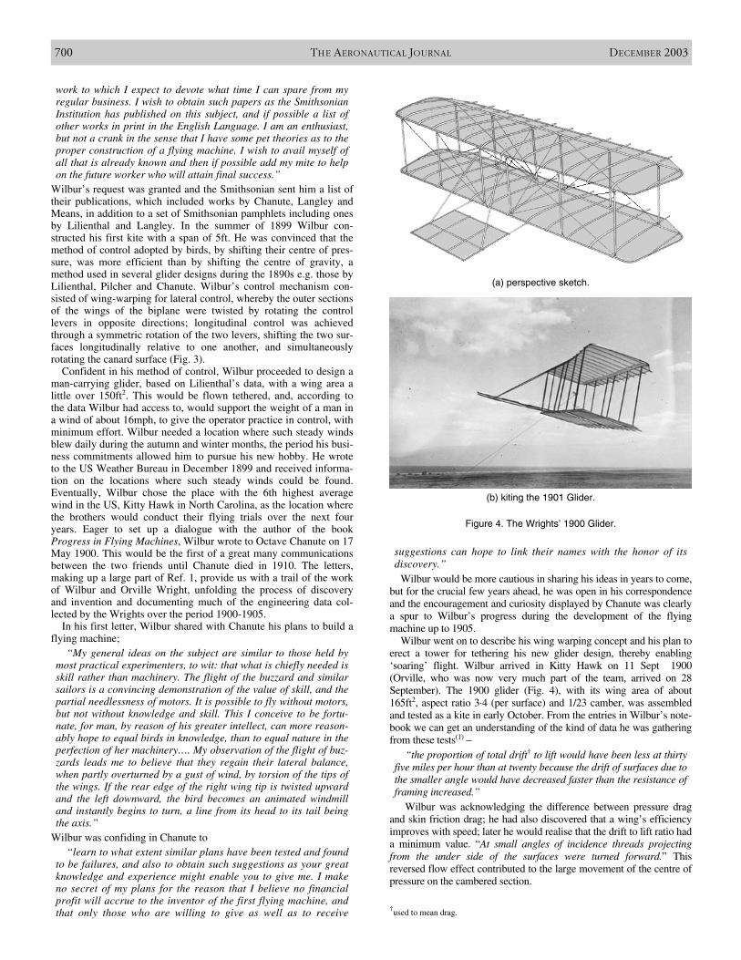
Wilbur went on to describe his wing warping concept and his plan toerect a tower for tethering his new glider design, thereby enabling‘soaring’ flight. Wilbur arrived in Kitty Hawk on 11 Sept 1900(Orville, who was now very much part of the team, arrived on 28September). The 1900 glider (Fig. 4), with its wing area of about165ft2, aspect ratio 3⋅4 (per surface) and 1/23 camber, was assembledand tested as a kite in early October. From the entries in Wilbur’s note-book we can get an understanding of the kind of data he was gatheringfrom these tests(1) –
“the proportion of total drift† to lift would have been less at thirtyfive miles per hour than at twenty because the drift of surfaces due tothe smaller angle would have decreased faster than the resistance offraming increased.”
Wilbur was acknowledging the difference between pressure dragand skin friction drag; he had also discovered that a wing’s efficiencyimproves with speed; later he would realise that the drift to lift ratio hada minimum value. “At small angles of incidence threads projectingfrom the under side of the surfaces were turned forward.” Thisreversed flow effect contributed to the large movement of the centre ofpressure on the cambered section.
700 THE AERONAUTICAL JOURNAL DECEMBER 2003
(a) perspective sketch.
Figure 4. The Wrights’ 1900 Glider.
(b) kiting the 1901 Glider.
†used to mean drag.
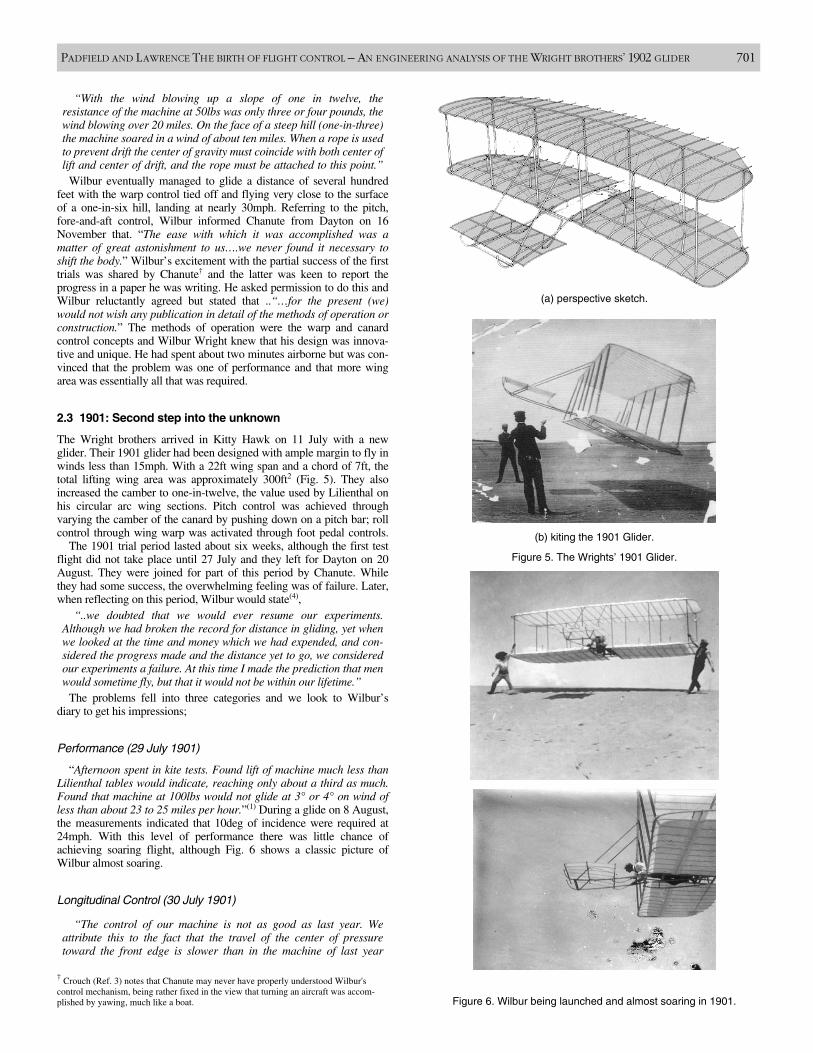
“With the wind blowing up a slope of one in twelve, the resistance of the machine at 50lbs was only three or four pounds, thewind blowing over 20 miles. On the face of a steep hill (one-in-three)the machine soared in a wind of about ten miles. When a rope is usedto prevent drift the center of gravity must coincide with both center oflift and center of drift, and the rope must be attached to this point.”
Wilbur eventually managed to glide a distance of several hundredfeet with the warp control tied off and flying very close to the surfaceof a one-in-six hill, landing at nearly 30mph. Referring to the pitch,fore-and-aft control, Wilbur informed Chanute from Dayton on 16November that. “The ease with which it was accomplished was amatter of great astonishment to us….we never found it necessary toshift the body.” Wilbur’s excitement with the partial success of the firsttrials was shared by Chanute† and the latter was keen to report theprogress in a paper he was writing. He asked permission to do this andWilbur reluctantly agreed but stated that ..“…for the present (we)would not wish any publication in detail of the methods of operation orconstruction.” The methods of operation were the warp and canardcontrol concepts and Wilbur Wright knew that his design was innova-tive and unique. He had spent about two minutes airborne but was con-vinced that the problem was one of performance and that more wingarea was essentially all that was required.
2.3 1901: Second step into the unknown
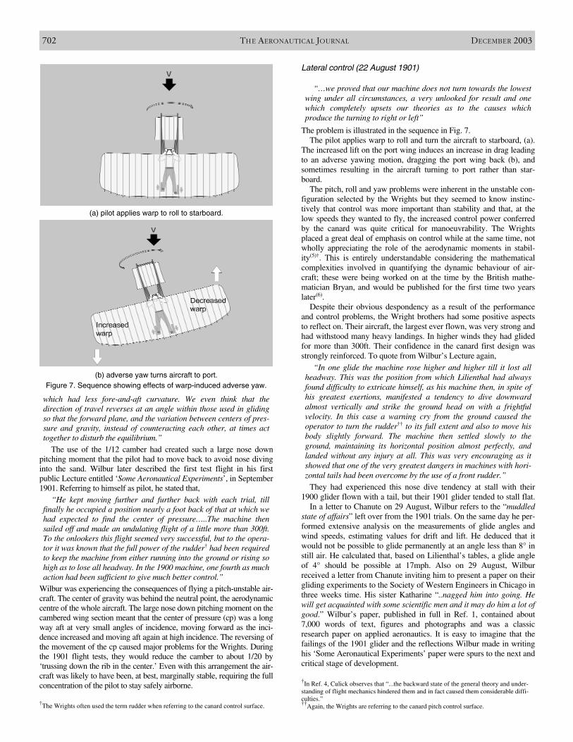
The Wright brothers arrived in Kitty Hawk on 11 July with a newglider. Their 1901 glider had been designed with ample margin to fly inwinds less than 15mph. With a 22ft wing span and a chord of 7ft, thetotal lifting wing area was approximately 300ft2 (Fig. 5). They alsoincreased the camber to one-in-twelve, the value used by Lilienthal onhis circular arc wing sections. Pitch control was achieved throughvarying the camber of the canard by pushing down on a pitch bar; rollcontrol through wing warp was activated through foot pedal controls.
The 1901 trial period lasted about six weeks, although the first testflight did not take place until 27 July and they left for Dayton on 20August. They were joined for part of this period by Chanute. Whilethey had some success, the overwhelming feeling was of failure. Later,when reflecting on this period, Wilbur would state(4),
“..we doubted that we would ever resume our experiments.Although we had broken the record for distance in gliding, yet whenwe looked at the time and money which we had expended, and con-sidered the progress made and the distance yet to go, we consideredour experiments a failure. At this time I made the prediction that menwould sometime fly, but that it would not be within our lifetime.”
The problems fell into three categories and we look to Wilbur’sdiary to get his impressions;
Performance (29 July 1901)
“Afternoon spent in kite tests. Found lift of machine much less thanLilienthal tables would indicate, reaching only about a third as much.Found that machine at 100lbs would not glide at 3° or 4° on wind ofless than about 23 to 25 miles per hour.”(1) During a glide on 8 August,the measurements indicated that 10deg of incidence were required at24mph. With this level of performance there was little chance ofachieving soaring flight, although Fig. 6 shows a classic picture ofWilbur almost soaring.
Longitudinal Control (30 July 1901)
“The control of our machine is not as good as last year. Weattribute this to the fact that the travel of the center of pressuretoward the front edge is slower than in the machine of last year
PADFIELD AND LAWRENCE THE BIRTH OF FLIGHT CONTROL – AN ENGINEERING ANALYSIS OF THE WRIGHT BROTHERS’ 1902 GLIDER 701
Figure 5. The Wrights’ 1901 Glider.
(b) kiting the 1901 Glider.
(a) perspective sketch.
Figure 6. Wilbur being launched and almost soaring in 1901.
† Crouch (Ref. 3) notes that Chanute may never have properly understood Wilbur'scontrol mechanism, being rather fixed in the view that turning an aircraft was accom-plished by yawing, much like a boat.
which had less fore-and-aft curvature. We even think that the direction of travel reverses at an angle within those used in glidingso that the forward plane, and the variation between centers of pres-sure and gravity, instead of counteracting each other, at times acttogether to disturb the equilibrium.”
The use of the 1/12 camber had created such a large nose downpitching moment that the pilot had to move back to avoid nose divinginto the sand. Wilbur later described the first test flight in his firstpublic Lecture entitled ‘Some Aeronautical Experiments’, in September1901. Referring to himself as pilot, he stated that,
“He kept moving further and further back with each trial, tillfinally he occupied a position nearly a foot back of that at which wehad expected to find the center of pressure…..The machine thensailed off and made an undulating flight of a little more than 300ft.To the onlookers this flight seemed very successful, but to the opera-tor it was known that the full power of the rudder† had been requiredto keep the machine from either running into the ground or rising sohigh as to lose all headway. In the 1900 machine, one fourth as muchaction had been sufficient to give much better control.”
Wilbur was experiencing the consequences of flying a pitch-unstable air-craft. The center of gravity was behind the neutral point, the aerodynamiccentre of the whole aircraft. The large nose down pitching moment on thecambered wing section meant that the center of pressure (cp) was a longway aft at very small angles of incidence, moving forward as the inci-dence increased and moving aft again at high incidence. The reversing ofthe movement of the cp caused major problems for the Wrights. Duringthe 1901 flight tests, they would reduce the camber to about 1/20 by‘trussing down the rib in the center.’ Even with this arrangement the air-craft was likely to have been, at best, marginally stable, requiring the fullconcentration of the pilot to stay safely airborne.
Lateral control (22 August 1901)
“…we proved that our machine does not turn towards the lowestwing under all circumstances, a very unlooked for result and onewhich completely upsets our theories as to the causes whichproduce the turning to right or left”
The problem is illustrated in the sequence in Fig. 7.The pilot applies warp to roll and turn the aircraft to starboard, (a).
The increased lift on the port wing induces an increase in drag leadingto an adverse yawing motion, dragging the port wing back (b), andsometimes resulting in the aircraft turning to port rather than star-board.
The pitch, roll and yaw problems were inherent in the unstable con-figuration selected by the Wrights but they seemed to know instinc-tively that control was more important than stability and that, at thelow speeds they wanted to fly, the increased control power conferredby the canard was quite critical for manoeuvrability. The Wrightsplaced a great deal of emphasis on control while at the same time, notwholly appreciating the role of the aerodynamic moments in stabil-ity(5)†. This is entirely understandable considering the mathematicalcomplexities involved in quantifying the dynamic behaviour of air-craft; these were being worked on at the time by the British mathe-matician Bryan, and would be published for the first time two yearslater(6).
Despite their obvious despondency as a result of the performanceand control problems, the Wright brothers had some positive aspectsto reflect on. Their aircraft, the largest ever flown, was very strong andhad withstood many heavy landings. In higher winds they had glidedfor more than 300ft. Their confidence in the canard first design wasstrongly reinforced. To quote from Wilbur’s Lecture again,
“In one glide the machine rose higher and higher till it lost allheadway. This was the position from which Lilienthal had alwaysfound difficulty to extricate himself, as his machine then, in spite ofhis greatest exertions, manifested a tendency to dive downwardalmost vertically and strike the ground head on with a frightfulvelocity. In this case a warning cry from the ground caused theoperator to turn the rudder†† to its full extent and also to move hisbody slightly forward. The machine then settled slowly to theground, maintaining its horizontal position almost perfectly, andlanded without any injury at all. This was very encouraging as itshowed that one of the very greatest dangers in machines with hori-zontal tails had been overcome by the use of a front rudder.”
They had experienced this nose dive tendency at stall with their1900 glider flown with a tail, but their 1901 glider tended to stall flat.
In a letter to Chanute on 29 August, Wilbur refers to the “muddledstate of affairs” left over from the 1901 trials. On the same day he per-formed extensive analysis on the measurements of glide angles andwind speeds, estimating values for drift and lift. He deduced that itwould not be possible to glide permanently at an angle less than 8° instill air. He calculated that, based on Lilienthal’s tables, a glide angleof 4° should be possible at 17mph. Also on 29 August, Wilburreceived a letter from Chanute inviting him to present a paper on theirgliding experiments to the Society of Western Engineers in Chicago inthree weeks time. His sister Katharine “..nagged him into going. Hewill get acquainted with some scientific men and it may do him a lot ofgood.” Wilbur’s paper, published in full in Ref. 1, contained about7,000 words of text, figures and photographs and was a classicresearch paper on applied aeronautics. It is easy to imagine that thefailings of the 1901 glider and the reflections Wilbur made in writinghis ‘Some Aeronautical Experiments’ paper were spurs to the next andcritical stage of development.
702 THE AERONAUTICAL JOURNAL DECEMBER 2003
(a) pilot applies warp to roll to starboard.
(b) adverse yaw turns aircraft to port.Figure 7. Sequence showing effects of warp-induced adverse yaw.
†The Wrights often used the term rudder when referring to the canard control surface.
†In Ref. 4, Culick observes that “...the backward state of the general theory and under-standing of flight mechanics hindered them and in fact caused them considerable diffi-culties.”††Again, the Wrights are referring to the canard pitch control surface.
3.0 1901-1902: INTERPRETING THEWRIGHTS’ PROCESS OF INVENTION
In Ref. 1, the account of activities during the period betweenOctober 1901 and February 1902 is documented in about 100 pagesof text, numerous table and figures, and is arguably the richestrecord of progress in the entire reference. Here we see the Wrightbrothers working together towards a greater understanding of theperformance problems they had experienced. They had made exten-sive use of Lilienthal’s data tables in their design and were perplexedby the results, losing confidence in the process. In a letter to Chanutewritten on 6 October 1901, Wilbur writes, “I am now absolutelycertain that Lilienthal’s table is very seriously in error…” Less thantwo weeks later, after painstaking analysis of available data Wilburwrote to Chanute again, describing a new balance they would beusing to measure lift and drift; Wilbur adds, “…It would appear thatLilienthal is very much nearer the truth than we have heretoforebeen disposed to think…” In this same month, Chanute would sendWilbur a translation copy of Lilienthal’s book(7), which would serveto inform him even further of the errors that both he and Lilienthalhad made; Wilbur’s letter to Chanute on 2 November(1) summarisinghis analysis of errors reads like a classic researcher’s logbook. Oneof the major discoveries made by Wilbur in the analysis of existingdata was the error in the, so-called, Smeaton coefficient in theexpression that Wilbur believed Lilienthal had used for computinglift,
Lift = k S V2 CL
k is the Smeaton coefficient of air pressure(8), S the wing area, V thevelocity and CL the lift coefficient. Wilbur assumed that Lilienthalhad used Smeaton’s value of 0⋅005 for k. In fact, Lilienthal had mea-sured CL directly and had no need to use the Smeaton coefficient, soWilbur’s back-calculation to estimate the required wing area andresulting glide angles were based on an erroneous assumption (Ref.8 gives a detailed explanation of how the interpretation error came topass). Wilbur had reported his suspicion that the Smeaton coefficientwas too high in his letter to Chanute on 26 Sept, “…ProfessorLangley and also the Weather Bureau officials found that the correctcoefficient of pressure was only about 0⋅0032, instead of Smeaton’s0⋅005…”. Wilbur had unearthed one of the reasons for the perfor-mance shortfall in the 1901 glider, but he was determined to estab-lish the optimum wing design.
With the purpose of creating a detailed aerodynamic database thatwould serve their design goals, the Wright brothers built a windtunnel and two force balance systems that would provide, effectively,direct measurements of the lift coefficient and the ratio of drift to lift.The operation of this balance is very well described by Jakab in Ref.3. They made measurements to examine the effect of a wide range ofdesign parameters – aspect ratio, camber, point of maximum camber,biplane surface spacing and others – on the lifting capacity and effi-ciency of the surfaces. Wilbur wrote to Chanute on 15 December,continuing the information exchange with a summary of the mainresults to date, but also indicating that the experimenting had now tostop to give way for bicycle making. In his letter Wilbur described‘laws’ for superimposing multiple surfaces, re-shaping single surfacesand revealed the major effect of aspect ratio on the lift curve slope.He emphasised the benefits of their systematic approach in thiscontext,
“It has been a great advantage we think to make a systematicmeasurement of several typical series of surfaces rather than towork blindly on all sorts of shapes, as a study of the series platesquickly discloses the general principles which govern lift and tan-gential and thus renders the search for the best shapes mucheasier. A mere glance shows that while increasing the ratio ofbreadth to length does not increase the maximum lift to any greatextent it does cause the maximum to be reached at a smallerangle; and the wider the spread from tip to tip the smaller theangle at which large lifts can be obtained.”
Wilbur’s breadth was what we now call the wing span while hislength was our chord. In this paragraph, he emphasised the word‘best’, acknowledging that the physics of aerodynamics clearly didfavour particular arrangements.
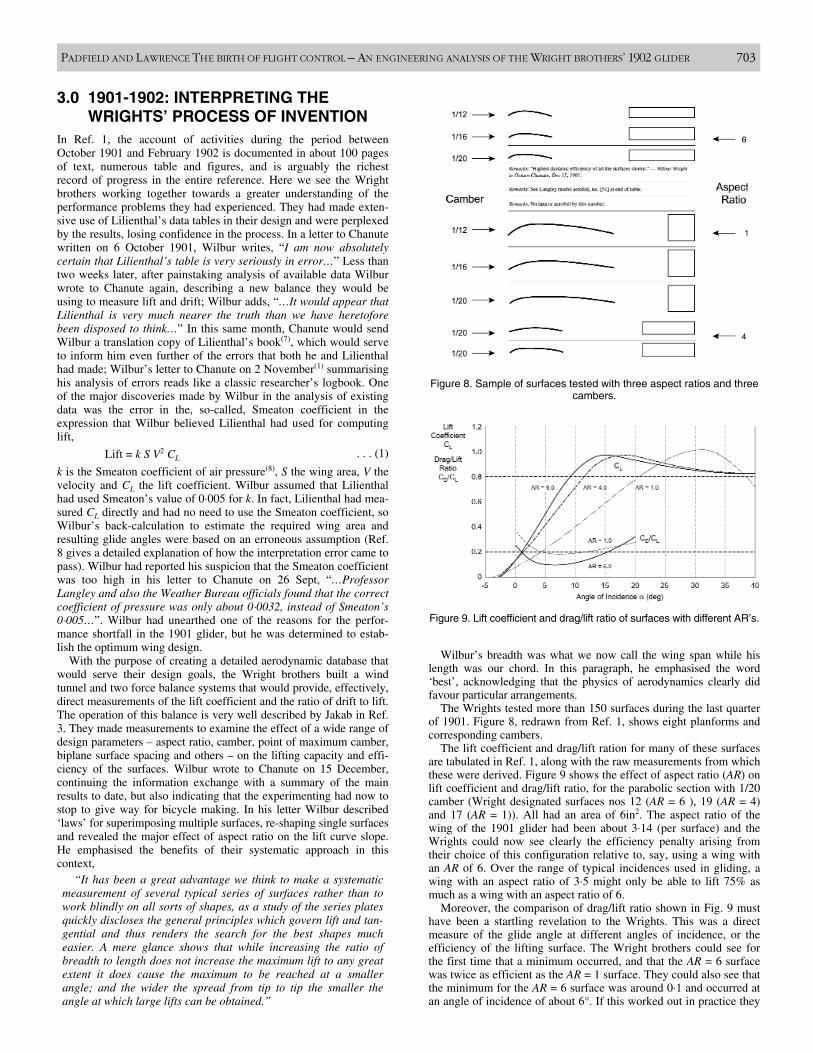
The Wrights tested more than 150 surfaces during the last quarterof 1901. Figure 8, redrawn from Ref. 1, shows eight planforms andcorresponding cambers.
The lift coefficient and drag/lift ration for many of these surfacesare tabulated in Ref. 1, along with the raw measurements from whichthese were derived. Figure 9 shows the effect of aspect ratio (AR) onlift coefficient and drag/lift ratio, for the parabolic section with 1/20camber (Wright designated surfaces nos 12 (AR = 6 ), 19 (AR = 4)and 17 (AR = 1)). All had an area of 6in2. The aspect ratio of thewing of the 1901 glider had been about 3⋅14 (per surface) and theWrights could now see clearly the efficiency penalty arising fromtheir choice of this configuration relative to, say, using a wing withan AR of 6. Over the range of typical incidences used in gliding, awing with an aspect ratio of 3⋅5 might only be able to lift 75% asmuch as a wing with an aspect ratio of 6.
Moreover, the comparison of drag/lift ratio shown in Fig. 9 musthave been a startling revelation to the Wrights. This was a directmeasure of the glide angle at different angles of incidence, or theefficiency of the lifting surface. The Wright brothers could see forthe first time that a minimum occurred, and that the AR = 6 surfacewas twice as efficient as the AR = 1 surface. They could also see thatthe minimum for the AR = 6 surface was around 0⋅1 and occurred atan angle of incidence of about 6°. If this worked out in practice they
PADFIELD AND LAWRENCE THE BIRTH OF FLIGHT CONTROL – AN ENGINEERING ANALYSIS OF THE WRIGHT BROTHERS’ 1902 GLIDER 703
Figure 8. Sample of surfaces tested with three aspect ratios and threecambers.
Figure 9. Lift coefficient and drag/lift ratio of surfaces with different AR’s.
. . . (1)
would be able to glide flat down a 6° slope! For the 1901 design,they had used a value of the pressure coefficient which was 50% toohigh and they could now see that by changing the aspect ratio from3⋅1 to perhaps 7, they could compensate for this error and design anew glider with essentially the same wing area as in their 1901machine. The aspect ratio effect came as a surprise to the Wrights,even though Lilienthal’s machine clearly had a higher ratio and theyhad used Lilienthal’s tables apparently oblivious to this importantdesign parameter. In Ref. 7, Lilienthal recommends particulardimensions; to quote from his list of ‘fundamental constructionpoints’;
“9th – It will be a matter of experiment to determine whetherthe broad shape of wing with resolved pinions, such as we see inbirds of prey, or the long pointed shape of wing of the sea birds,are preferable.
10th – In the former case the dimensions of the wing would be8m span, and 1⋅6m greatest width (AR = 5).
11th – When employing the slender wing shape, the correspond-ing dimensions would be 11m span and 1⋅4m greatest width(AR=7⋅9).”
Wilbur had written in his letter to Chanute on 24 November that,
“It is very evident from these measurements that a table basedon one aspect and profile is worthless for a surface of differentaspect and curvature. This no doubt explains why we have had somuch trouble figuring all our machines from Lilienthal’s table.”
In his book, A History of Aerodynamics(8), John Anderson pro-vides a comprehensive analysis of the causes of the under-perfor-mance in the Wrights’ 1901 glider, compared with their expectations– a combination of using a lower aspect ratio than Lilienthal, using aparabolic section rather than a circular arc and using a pressure coef-ficient of 0⋅005, meant that the Wrights’ lift calculations were inerror by a factor of 0⋅36, correlating very closely with Wilbur’sassertion recorded in his diary on 29 July 1901, that they, “..Foundlift of machine much less than Lilienthal tables would indicate,reaching only about 1/3rd as much.”
The wind tunnel experiments conducted during the months ofOctober to December 1901 had provided the Wrights with theanswers to the performance questions arising from their 1901 flighttrials. For Wilbur and Orville Wright, the control and stability prob-lems were intractable to solution at model scale or by analysis, andthey would have to wait until the next flight tests to address these.
On 20 August 1902, Katharine Wright, in a letter to her father,writes,
“…The flying machine is in process of making now. Will spinsthe sewing machine around by the hour while Orv squats aroundmarking the places to sew. There is no place in the house to livebut I’ll be lonesome enough by this time next week and wish that Icould have some of their racket around….”
By ‘this time next week’, Wilbur and Orville had left for KittyHawk, arriving on Thursday 28 August to undertake their thirdflight trial.
4.0 OCTOBER 1902: THE BIRTH OFTHREE-AXIS FLIGHT CONTROL
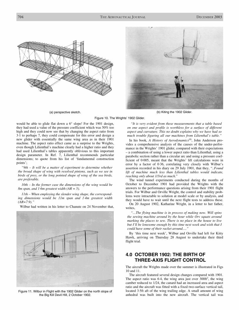
The aircraft the Wrights made over the summer is illustrated in Figs10 and 11.
The aircraft featured several design changes compared with 1901.The aspect ratio was 6⋅4, the wing area just over 300ft2, the wingcamber reduced to 1/24, the canard had an increased area and aspectratio and the aircraft was fitted with a fixed two-surface vertical tail,located 3⋅5ft aft of the wing trailing edge. A small amount of winganhedral was built into the new aircraft. The vertical tail was
704 THE AERONAUTICAL JOURNAL DECEMBER 2003
(a) perspective sketch. (b) Kiting the 1902 Glider.
Figure 10. The Wrights’ 1902 Glider.
Figure 11. Wilbur in Flight with the 1902 Glider on the north slope ofthe Big Kill Devil Hill, 2 October 1902.
included to compensate for the adverse yaw caused by wing warp,but they may also have anticipated the adverse effects of anhedralwith this design feature. It is interesting to note that the wing camberand aspect ratio of the new design was not one that they had tested intheir wind tunnel during the winter. The Wrights’ also changed thecontrol mechanism for warp and canard pitch. Wing warping waseffected by the operator moving his hips in a cradle in the directionof turn and the canard was now operated by a twist bar – twisting upfor increased pitch.
Wilbur recorded his satisfaction with the first kite tests (see Fig.10) in a letter, written on 16 September, to his aeronautical col-league, George Spratt, who had joined the 1901 trials for a period.
“We had it out making some tests of its efficiency today and arevery much pleased with the results of our measurements. ….In atest for soaring as a kite the cords stood vertical or a little to thefront on a hill having a slope of only 7⋅5°, (see Fig. 10(b)). This isan immense improvement over our last year’s machine whichwould soar only when the slope was 15° to 20°, as you willremember.”
They began testing on 19 Sept and made about 50 glides duringthe first two days. Wilbur crashed during one glide when he inadver-tently increased the canard pitch when the glider began rolling due toa port gust. In a letter to Chanute, written on a rainy Sunday, 21Sept, Wilbur invited Chanute to join the trial and noted that, “I madea glide of 140ft at an angle of 7º 10′ on a straight slope whose great-est inclination was 7º 30′, exactly facing the wind, at a speed ofabout 10 miles over ground, and wind of nine miles, a total of notover 19 miles.” Their prediction that they would be able to glide at 7ºappeared to be correct and they could now look forward to manyhours learning to fly. However, during the following Tuesday, whenthey made about 75 glides, Orville, on his first ‘free’ flight, had aserious crash, surviving “..without a bruise or a scratch.” Theproblem stemmed from the strong coupling between longitudinaland lateral motions (incidence and sideslip) when the aircraft beganto yaw, although Wilbur and Orville could not agree on the exactnature of the problem(1).
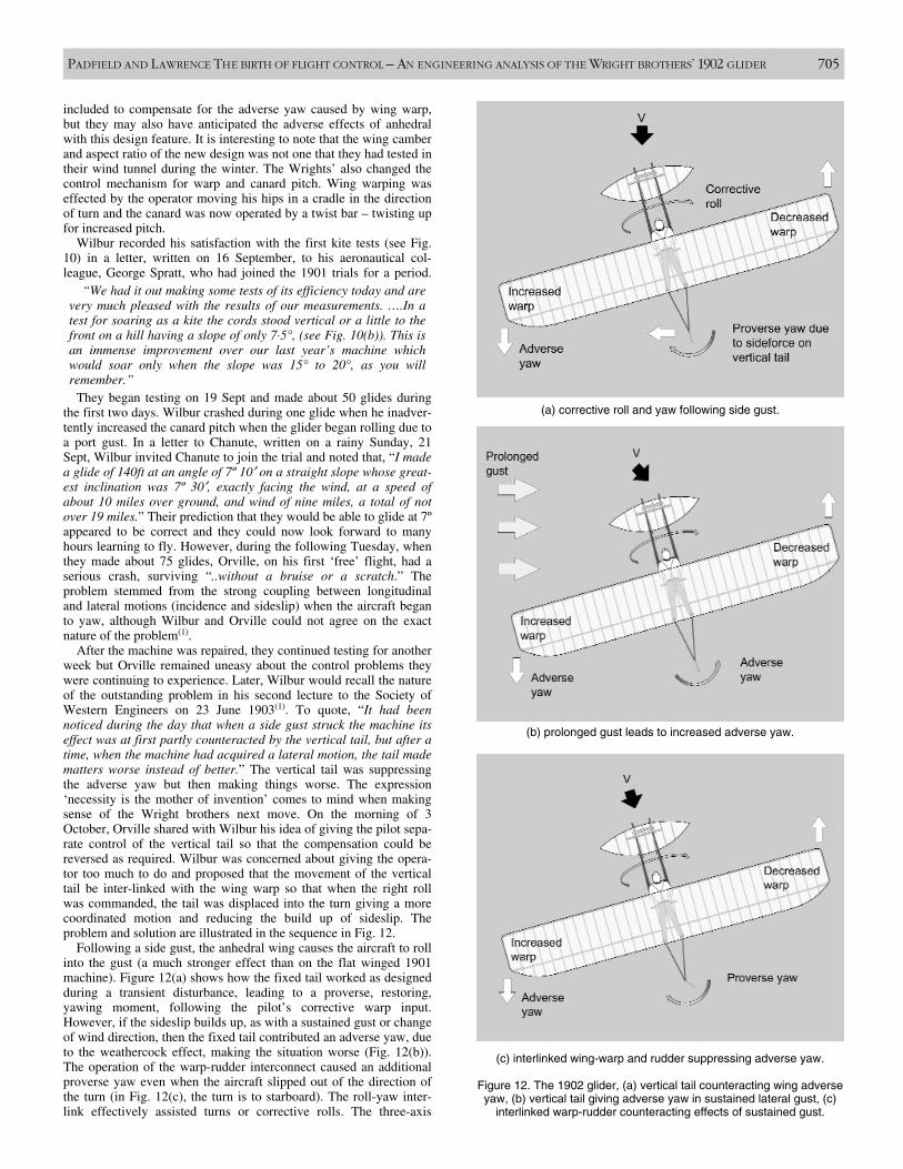
After the machine was repaired, they continued testing for anotherweek but Orville remained uneasy about the control problems theywere continuing to experience. Later, Wilbur would recall the natureof the outstanding problem in his second lecture to the Society ofWestern Engineers on 23 June 1903(1). To quote, “It had beennoticed during the day that when a side gust struck the machine itseffect was at first partly counteracted by the vertical tail, but after atime, when the machine had acquired a lateral motion, the tail madematters worse instead of better.” The vertical tail was suppressingthe adverse yaw but then making things worse. The expression‘necessity is the mother of invention’ comes to mind when makingsense of the Wright brothers next move. On the morning of 3October, Orville shared with Wilbur his idea of giving the pilot sepa-rate control of the vertical tail so that the compensation could bereversed as required. Wilbur was concerned about giving the opera-tor too much to do and proposed that the movement of the verticaltail be inter-linked with the wing warp so that when the right rollwas commanded, the tail was displaced into the turn giving a morecoordinated motion and reducing the build up of sideslip. Theproblem and solution are illustrated in the sequence in Fig. 12.
Following a side gust, the anhedral wing causes the aircraft to rollinto the gust (a much stronger effect than on the flat winged 1901machine). Figure 12(a) shows how the fixed tail worked as designedduring a transient disturbance, leading to a proverse, restoring,yawing moment, following the pilot’s corrective warp input.However, if the sideslip builds up, as with a sustained gust or changeof wind direction, then the fixed tail contributed an adverse yaw, dueto the weathercock effect, making the situation worse (Fig. 12(b)).The operation of the warp-rudder interconnect caused an additionalproverse yaw even when the aircraft slipped out of the direction ofthe turn (in Fig. 12(c), the turn is to starboard). The roll-yaw inter-link effectively assisted turns or corrective rolls. The three-axis
PADFIELD AND LAWRENCE THE BIRTH OF FLIGHT CONTROL – AN ENGINEERING ANALYSIS OF THE WRIGHT BROTHERS’ 1902 GLIDER 705
(a) corrective roll and yaw following side gust.
(c) interlinked wing-warp and rudder suppressing adverse yaw.
(b) prolonged gust leads to increased adverse yaw.
Figure 12. The 1902 glider, (a) vertical tail counteracting wing adverseyaw, (b) vertical tail giving adverse yaw in sustained lateral gust, (c)
interlinked warp-rudder counteracting effects of sustained gust.
control system would later feature as the basis of the WrightBrother’s patent, first applied for in 1903 and finally granted in theUnited States in 1906†.
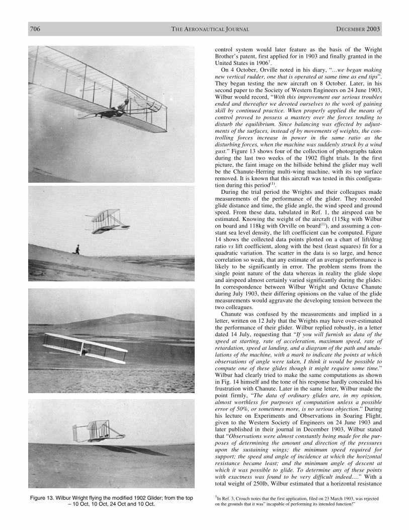
On 4 October, Orville noted in his diary, “…we began makingnew vertical rudder, one that is operated at same time as end tips”.They began testing the new aircraft on 8 October. Later, in hissecond paper to the Society of Western Engineers on 24 June 1903,Wilbur would record, “With this improvement our serious troublesended and thereafter we devoted ourselves to the work of gainingskill by continued practice. When properly applied the means ofcontrol proved to possess a mastery over the forces tending todisturb the equilibrium. Since balancing was effected by adjust-ments of the surfaces, instead of by movements of weights, the con-trolling forces increase in power in the same ratio as thedisturbing forces, when the machine was suddenly struck by a windgust.” Figure 13 shows four of the collection of photographs takenduring the last two weeks of the 1902 flight trials. In the firstpicture, the faint image on the hillside behind the glider may wellbe the Chanute-Herring multi-wing machine, with its top surfaceremoved. It is known that this aircraft was tested in this configura-tion during this period(1).
During the trial period the Wrights and their colleagues mademeasurements of the performance of the glider. They recordedglide distance and time, the glide angle, the wind speed and groundspeed. From these data, tabulated in Ref. 1, the airspeed can beestimated. Knowing the weight of the aircraft (115kg with Wilburon board and 118kg with Orville on board(1)), and assuming a con-stant sea level density, the lift coefficient can be computed. Figure14 shows the collected data points plotted on a chart of lift/dragratio vs lift coefficient, along with the best (least squares) fit for aquadratic variation. The scatter in the data is so large, and hencecorrelation so weak, that any estimate of an average performance islikely to be significantly in error. The problem stems from thesingle point nature of the data whereas in reality the glide slopeand airspeed almost certainly varied significantly during the glides.In correspondence between Wilbur Wright and Octave Chanuteduring July 1903, their differing opinions on the value of the glidemeasurements would aggravate the developing tension between thetwo colleagues.
Chanute was confused by the measurements and implied in aletter, written on 12 July that the Wrights may have over-estimatedthe performance of their glider. Wilbur replied robustly, in a letterdated 14 July, requesting that “If you will furnish us data of thespeed at starting, rate of acceleration, maximum speed, rate ofretardation, speed at landing, and a diagram of the path and undu-lations of the machine, with a mark to indicate the points at whichobservations of angle were taken, I think it would be possible tocompute one of these glides though it might require some time.”Wilbur had clearly tried to make the same computations as shownin Fig. 14 himself and the tone of his response hardly concealed hisfrustration with Chanute. Later in the same letter, Wilbur made thepoint firmly, “The data of ordinary glides are, in my opinion,almost worthless for purposes of computation unless a possibleerror of 50%, or sometimes more, is no serious objection.” Duringhis lecture on Experiments and Observations in Soaring Flight,given to the Western Society of Engineers on 24 June 1903 andlater published in their journal in December 1903, Wilbur statedthat “Observations were almost constantly being made for the pur-poses of determining the amount and direction of the pressuresupon the sustaining wings; the minimum speed required forsupport; the speed and angle of incidence at which the horizontalresistance became least; and the minimum angle of descent atwhich it was possible to glide. To determine any of these pointswith exactness was found to be very difficult indeed….” With atotal weight of 250lb, Wilbur estimated that a horizontal resistance
706 THE AERONAUTICAL JOURNAL DECEMBER 2003
Figure 13. Wilbur Wright flying the modified 1902 Glider; from the top– 10 Oct, 10 Oct, 24 Oct and 10 Oct.
†In Ref. 3, Crouch notes that the first application, filed on 23 March 1903, was rejectedon the grounds that it was” incapable of performing its intended function!”
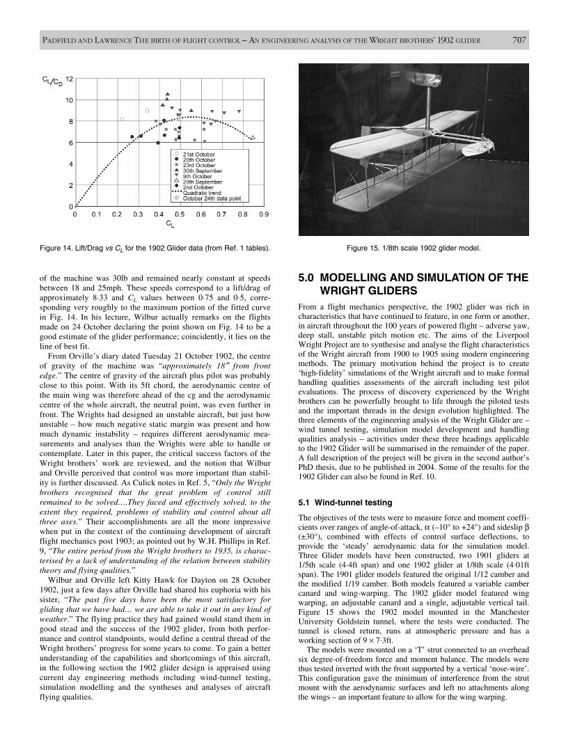
of the machine was 30lb and remained nearly constant at speedsbetween 18 and 25mph. These speeds correspond to a lift/drag ofapproximately 8⋅33 and CL values between 0⋅75 and 0⋅5, corre-sponding very roughly to the maximum portion of the fitted curvein Fig. 14. In his lecture, Wilbur actually remarks on the flightsmade on 24 October declaring the point shown on Fig. 14 to be agood estimate of the glider performance; coincidently, it lies on theline of best fit.
From Orville’s diary dated Tuesday 21 October 1902, the centreof gravity of the machine was “approximately 18″ from frontedge.” The centre of gravity of the aircraft plus pilot was probablyclose to this point. With its 5ft chord, the aerodynamic centre ofthe main wing was therefore ahead of the cg and the aerodynamiccentre of the whole aircraft, the neutral point, was even further infront. The Wrights had designed an unstable aircraft, but just howunstable – how much negative static margin was present and howmuch dynamic instability – requires different aerodynamic mea-surements and analyses than the Wrights were able to handle orcontemplate. Later in this paper, the critical success factors of theWright brothers’ work are reviewed, and the notion that Wilburand Orville perceived that control was more important than stabil-ity is further discussed. As Culick notes in Ref. 5, “Only the Wrightbrothers recognised that the great problem of control stillremained to be solved….They faced and effectively solved, to theextent they required, problems of stability and control about allthree axes.” Their accomplishments are all the more impressivewhen put in the context of the continuing development of aircraftflight mechanics post 1903; as pointed out by W.H. Phillips in Ref.9, “The entire period from the Wright brothers to 1935, is charac-terised by a lack of understanding of the relation between stabilitytheory and flying qualities.”
Wilbur and Orville left Kitty Hawk for Dayton on 28 October1902, just a few days after Orville had shared his euphoria with hissister, “The past five days have been the most satisfactory forgliding that we have had… we are able to take it out in any kind ofweather.” The flying practice they had gained would stand them ingood stead and the success of the 1902 glider, from both perfor-mance and control standpoints, would define a central thread of theWright brothers’ progress for some years to come. To gain a betterunderstanding of the capabilities and shortcomings of this aircraft,in the following section the 1902 glider design is appraised usingcurrent day engineering methods including wind-tunnel testing,simulation modelling and the syntheses and analyses of aircraftflying qualities.
5.0 MODELLING AND SIMULATION OF THEWRIGHT GLIDERS
From a flight mechanics perspective, the 1902 glider was rich incharacteristics that have continued to feature, in one form or another,in aircraft throughout the 100 years of powered flight – adverse yaw,deep stall, unstable pitch motion etc. The aims of the LiverpoolWright Project are to synthesise and analyse the flight characteristicsof the Wright aircraft from 1900 to 1905 using modern engineeringmethods. The primary motivation behind the project is to create‘high-fidelity’ simulations of the Wright aircraft and to make formalhandling qualities assessments of the aircraft including test pilotevaluations. The process of discovery experienced by the Wrightbrothers can be powerfully brought to life through the piloted testsand the important threads in the design evolution highlighted. Thethree elements of the engineering analysis of the Wright Glider are –wind tunnel testing, simulation model development and handlingqualities analysis – activities under these three headings applicableto the 1902 Glider will be summarised in the remainder of the paper.A full description of the project will be given in the second author’sPhD thesis, due to be published in 2004. Some of the results for the1902 Glider can also be found in Ref. 10.
5.1 Wind-tunnel testing
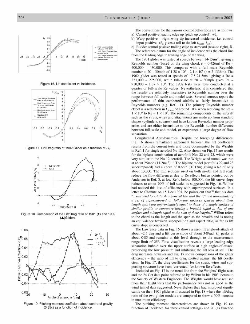
The objectives of the tests were to measure force and moment coeffi-cients over ranges of angle-of-attack, α (–10° to +24°) and sideslip β(±30°), combined with effects of control surface deflections, toprovide the ‘steady’ aerodynamic data for the simulation model.Three Glider models have been constructed, two 1901 gliders at1/5th scale (4⋅4ft span) and one 1902 glider at 1/8th scale (4⋅01ftspan). The 1901 glider models featured the original 1/12 camber andthe modified 1/19 camber. Both models featured a variable cambercanard and wing-warping. The 1902 glider model featured wingwarping, an adjustable canard and a single, adjustable vertical tail.Figure 15 shows the 1902 model mounted in the ManchesterUniversity Goldstein tunnel, where the tests were conducted. Thetunnel is closed return, runs at atmospheric pressure and has aworking section of 9 × 7⋅3ft.
The models were mounted on a ‘T’ strut connected to an overheadsix degree-of-freedom force and moment balance. The models werethus tested inverted with the front supported by a vertical ‘nose-wire’.This configuration gave the minimum of interference from the strutmount with the aerodynamic surfaces and left no attachments alongthe wings – an important feature to allow for the wing warping.
PADFIELD AND LAWRENCE THE BIRTH OF FLIGHT CONTROL – AN ENGINEERING ANALYSIS OF THE WRIGHT BROTHERS’ 1902 GLIDER 707
Figure 14. Lift/Drag vs CL for the 1902 Glider data (from Ref. 1 tables). Figure 15. 1/8th scale 1902 glider model.
The conventions for the various control deflections are as follows:a) Canard positive leading edge up (pitch up control), +δcb) Warp positive – right wing tip increased incidence, i.e. control
input positive, +δw gives a roll to the left (iright–ileft).c) Rudder control positive trailing edge to starboard (nose to right), δr.
The reference datum for the angle of incidence was the chord linefrom the leading edge to trailing edge of the wing.
The 1901 glider was tested at speeds between 14-15ms-1, giving aReynolds number (based on the wing chord, c = 0⋅426m) of Re =400,000 – 430,000. This compares with a full scale Reynoldsnumber at 20 – 30mph of 1⋅28 × 106 – 2⋅1 × 106 (c = 2⋅1336m). The1902 glider was tested at speeds of 17⋅5-21⋅5ms-1 giving a Re =223,000 – 275,000, while full-scale at 20 – 30mph gives Re =910,000 – 1⋅37 × 106. The 1902 tests were thus conducted at aquarter of full-scale Re values. Nevertheless, it is considered thatthe results are relatively insensitive to Reynolds number over therange between full scale and model tests. Several sources report theperformance of thin cambered airfoils as fairly insensitive toReynolds numbers (e.g. Ref. 11). The primary Reynolds numbereffect is a reduction in CLmax of around 10% when reducing the Re ≈1 × 10⁶ to Re ≈ 1 × 10⁵. The remaining components of the aircraftsuch as the struts, wires and attachments are made up from standardshapes (cylinders, squares) and have known Reynolds number prop-erties and are either insensitive to the Reynolds number differencebetween full-scale and model, or experience a large degree of flowseparation.
Longitudinal Aerodynamics; Despite the foregoing differences,Fig. 16 shows remarkable agreement between the lift coefficientresults from the current tests and those documented by the Wrightsin Ref. 1 for single aerofoil No 12. Also shown on Fig. 17 are resultsfor the biplane combination of aerofoils Nos 22 and 23, which werevery similar to the No 12 aerofoil. The Wright wind tunnel was runat about 25mph (11⋅2ms-1)(1). The biplane model (aerofoils 22 and 23superimposed) had a chord of 0⋅66in (0⋅017m) giving a Re of onlyabout 13,000. The thin sections used on both model and full scalereduce the flow differences due to Re effects but as pointed out byAnderson in Ref. 8, at low Re’s, below 100,000, the lift curve slopereduces to about 70% of full scale, as suggested in Fig. 16. Wilburhad noticed this loss of efficiency with superimposed surfaces. In aletter to Chanute on 15 Dec 1901, he points out that(1) that his data“...will tend to establish a general law that the lift and tangentials ofa set of superimposed or following surfaces spaced about theirlength apart are approximately equal to those of a single surface ofsimilar profile or curvature having a breadth equal to that of onesurface and a length equal to the sum of their lengths.” Wilbur refersto the chord as the length and the span as the breadth and is notingan equivalence between superposition and aspect ratio, as far as liftcurve slope is concerned.
The Lawrence data in Fig. 16 shows a zero-lift angle-of-attack ofabout –2⋅5 deg and a lift curve slope of about 3⋅8/rad. CL peaks atabout 0⋅85 and remains at this level through to the measurementrange limit of 25°. Flow visualisation reveals a large leading-edgeseparation bubble over the upper surface at high angles-of-attack,preserving the low pressure and inhibiting the lift loss at stall. Thedrag increases however and Fig. 17 shows comparisons of the gliderefficiency – the ratio of lift to drag, plotted against the lift coeffi-cient. In Fig. 17, the drag coefficients for the struts, wires and sup-porting structure have been ‘corrected’ for known Re effects.
Included on Fig. 17 is the trend line from the Wrights’ flight testsand the 24 Oct data point referred to by Wilbur in his 1903 lecture tothe Society of Western Engineers. The Wrights would have realisedfrom their flight tests that the performance was not as good as thewind tunnel data suggested. Nevertheless they had improved signifi-cantly on their 1901 glider as illustrated in Fig. 18 where the lift/dragratio of the two glider models are compared to show a 60% increasein maximum efficiency.
The pitching moment characteristics are shown in Fig. 19 (asfunction of incidence for three canard settings) and 20 (as function
708 THE AERONAUTICAL JOURNAL DECEMBER 2003
Figure 16. Lift coefficient vs Incidence.
Figure 17. Lift/Drag ratio of 1902 Glider as a function of CL.
Figure 18. Comparison of the Lift/Drag ratio of 1901 (•) and 1902(�)Gliders.
Figure 19. Pitching moment coefficient about centre of gravity (0⋅35c) as a function of incidence.
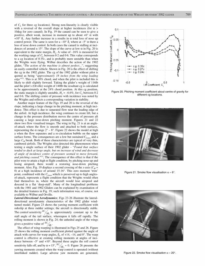
of CL for three cg locations). Strong non-linearity is clearly visiblewith a reversal of the overall slope at higher incidences (for α >10deg for zero canard). In Fig. 19 the canard can be seen to give apositive, albeit weak, increase in moment up to about +6° α with+10° δc. Any further increase in a results in α total loss of nose upcontrol power. The same is seen for a –10° δc where at –5° α there aloss of nose down control. In both cases the canard is stalling at inci-dences of around ± 15°. The slope of the curve at low α in Fig. 20 isequivalent to the static margin, Hn. A value of –16% is measured forthe working range of CL between 0⋅2 and 0⋅6. This value correspondsto a cg location of 0⋅35c, and is probably more unstable than whenthe Wrights were flying. Wilbur describes the action of the 1902glider, “The action of the machine is almost perfect…”, suggestingan easily controlled vehicle. Shown in Fig. 20 is the effect of shiftingthe cg in the 1902 glider. The cg of the 1902 glider without pilot isquoted as being “approximately 18 inches from the wing leadingedge”(1). This is at 30% chord, and when the pilot is included this islikely to shift slightly forward. Taking the glider’s weight of 116lband the pilot’s (Orville) weight of 140lb the resultant cg is calculatedto be approximately at the 24% chord position. At this cg position,the static margin is slightly unstable, Hn = –6.6%, for CL between 0⋅2and 0⋅6. The shifting centre of pressure with incidence was noted bythe Wrights and reflects a corresponding variation in stability.
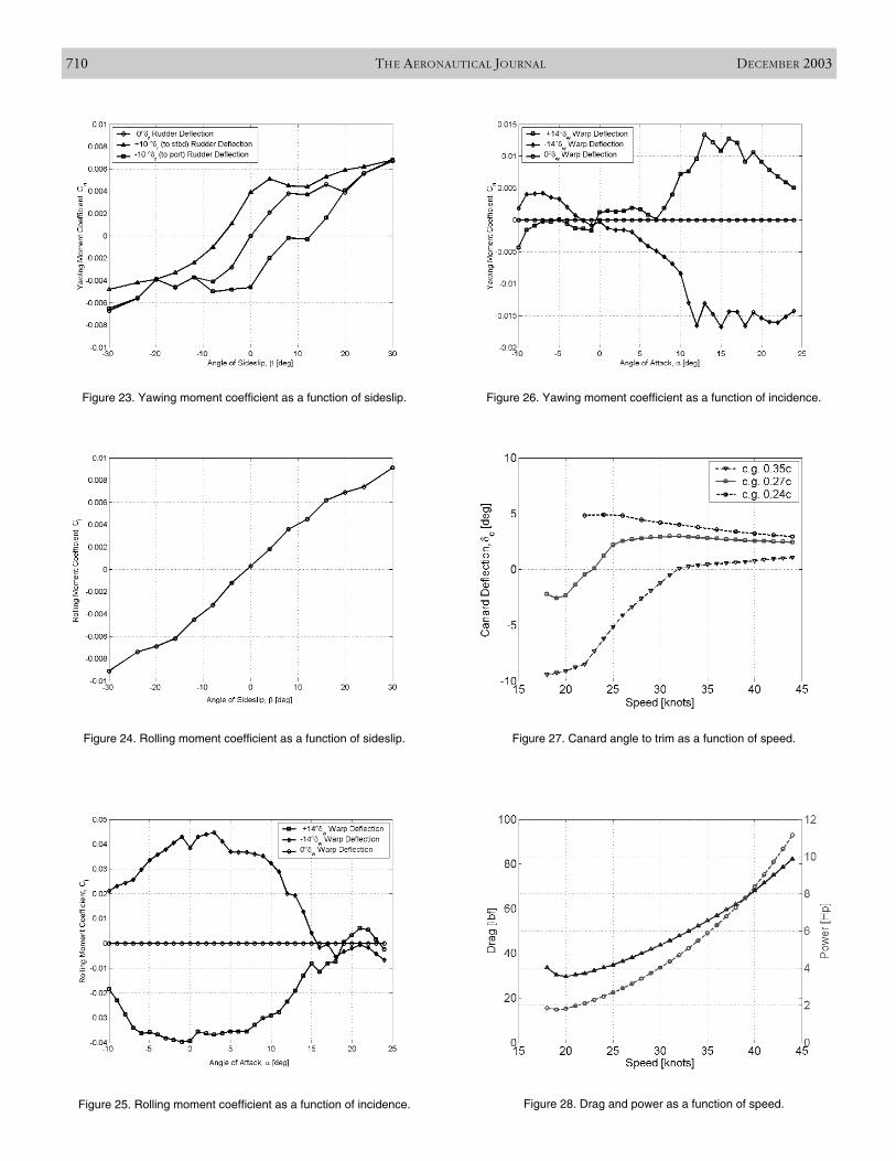
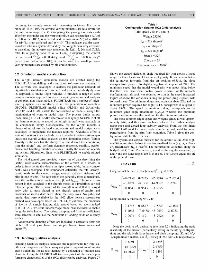
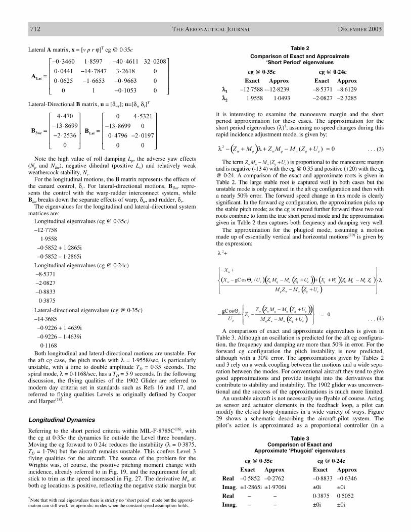
Another major feature of the Figs 19 and 20 is the reversal of theslope, indicating a large change in the pitching moment, at high inci-dence. This effect is due to separated flow near the leading edge ofthe airfoil. At high incidence, the wing continues to create lift, but achange in the pressure distribution moves the centre of pressure aftcausing a large nose-down pitching moment. Figures 21 and 22show two flow visualised images. The wing in Fig. 21 is at an angle-of-attack where the flow is smooth and attached to both surfaces,representing the α range 2° – 8°. Figure 22 shows the model at higha when the flow separates and a re-circulation bubble on the uppersurface forms. The consequences are a low but sustained CLmax and alarge CM break. Both of these characteristics are typical of very thin,cambered airfoils. The Wrights also detected this phenomenon whentesting a single surface of their 1902 glider – “Found that surfacetended to duck at large angle, but on increase of wind and decreaseof angle of incidence centre of pressure seemed to move forward,and pitching ceased.”(1), The consequence of this effect is that if thepilot were to attain a high α flight condition, by pitching nose-up andlosing airspeed, there would a restoring nose-down pitchingmoment. Also, Fig. 19 displays a second crossing of the x-axis (CM =0) at a high incidence of around 15-16°. This zero moment ‘trim’point, combined with the CLmax which is preserved up to high angles-of-attack, represents a flight condition that the Wrights would oftenfind themselves in, where the aircraft would lose airspeed anddescend in a flat ‘deep-stall’. Many of the longitudinal problemswith the 1901 and 1902 Gliders can be explained by examination ofthe detailed features in Fig. 19; such information was, of course, notavailable to Wilbur and Orville.Lateral-Directional Aerodynamics; Figs 23-26 illustrate the lateral-directional aerodynamic characteristics of the 1902 glider wind-tunnel model. Figure 23 shows the yawing moment coefficient withsideslip at three rudder settings; the aircraft is directionally stable.The control sensitivity is approximately constant up to thestall angle of the tail surface, whereupon it falls off rapidly. Therolling moment is shown in Fig. 24; the anhedral angle of the wingsgives a positive value of .
The effect of wing-warping is illustrated in Figs 25 and 26. Figure25 shows the rolling moment coefficient plotted against the angle ofattack with curves for warp angles, δw of +14, –14, and 0°. The warpcontrol is effective at creating rolling moments at angles of inci-dence between –5° and +10°. Beyond these angles the roll control sensitivity falls off, and by α = 15°, ≈ 0. Figure 26 presents theyawing moments created when the warp control is operated (withoutinterlinked rudder). Large adverse yaw moments are generated,
PADFIELD AND LAWRENCE THE BIRTH OF FLIGHT CONTROL – AN ENGINEERING ANALYSIS OF THE WRIGHT BROTHERS’ 1902 GLIDER 709
Figure 20. Pitching moment coefficient about centre of gravity for different cg locations.
Figure 22. Smoke flow visualisation α ≈ 20°.
Figure 21. Smoke flow visualisation α ≈ 6°.
n
r
C∂∂δ
lC∂∂β
l
w
C∂∂δ
710 THE AERONAUTICAL JOURNAL DECEMBER 2003
Figure 23. Yawing moment coefficient as a function of sideslip.
Figure 24. Rolling moment coefficient as a function of sideslip.
Figure 26. Yawing moment coefficient as a function of incidence.
Figure 27. Canard angle to trim as a function of speed.
Figure 25. Rolling moment coefficient as a function of incidence. Figure 28. Drag and power as a function of speed.
becoming increasingly worse with increasing incidence. For the αrange of –5 to +10°, the adverse yawing moments are less severe forthe maximum warp of ±14°. Comparing the yawing moments avail-able from the rudder and the warp controls, it can be seen that a ∆Cn of≈ ±0⋅004 for ±10° δr is achieved, and the maximum ∆Cn of ≈ ±0⋅005for ±14°δw is not achieved until α = 10°. This indicates that the warp-to-rudder interlink system devised by the Wrights was very effectiveat cancelling the adverse yaw moments. In Ref. 12, Jex and Culickrefer to a gearing ratio of δr = 1⋅25δw. Comparing the controlderivatives of = 0⋅0004deg-1 and = 0⋅00036 deg-1
(worst case below α = 10°), it can be seen that small proverseyawing moments are created by hip cradle motion.
5.2 Simulation model construction
The Wright aircraft simulation models are created using theFLIGHTLAB modelling and simulation software environment(13).The software was developed to address the particular demands ofhigh-fidelity simulation of rotorcraft and uses a multi-body dynam-ics approach to model flight vehicles. It provides a range of toolsusing a modular approach to assist in rapid generation and analysisof complex, non-linear models. FLIGHTLAB has a number of ‘high-level’ graphical user interfaces to aid the generation of models –GSCOPE, FLIGHTLAB model editor (FLME) and XAnalysis.GSCOPE and FLME enable the construction of models through themanipulation of icons or model trees. The process builds scripts(code) using FLIGHTLAB’s interpretative language SCOPE. Not allthe features required to model the Wright aircraft were available inthe component library. Consequently, for the Wright models, alibrary of novel user-defined components and model scripts weredeveloped to implement the features required. XAnalysis offers asuite of functions that enable the user to conduct control system syn-thesis and overall vehicle analyses on the simulation model. WithinXAnalysis, the user has the ability to set the desired test conditions,trim the aircraft and perform dynamic response, stability, perfor-mance and handling qualities analyses. Finally the real-time operat-ing system, Pilotstation, links with FLIGHTLAB to enable pilotedsimulation.
The wind tunnel tests provided a new set of data describing the(static) aerodynamic characteristics of the aircraft as a whole. Inorder to incorporate this data a multiple lookup table, ‘super-compo-nent’, was developed. This component calculates the total aerody-namic loads for the canard, wings, vertical surfaces, airframe andpilot in one system. The aero-tables are generally three dimensional,with the coefficients a function of α, β, and δcontrol. The super com-ponent is then attached to the aircraft model at a predefined airloadreference point. The structure of the aircraft is modelled as a rigidbody with a mass placed at the aircraft centre-of-gravity andmoments of inertia distributed about the body axes. No publishedinertial data were available for the 1902 glider hence a spreadsheetmethod was developed, based on Ref. 14, to estimate the momentsof inertia. A simple landing skid model based on the standardFLIGHTLAB two-strut undercarriage model was included to enablethe glider to be landed. The spring, damping and friction coefficientswere selected to emulate the behaviour of landing skids on a sandysurface.
Aerodynamic damping effects are included in derivative form forpitch, roll and yaw based on simple linear, two-dimensionaltheory(15).
5.3 Handling qualities analysis
Handling Qualities analysis addresses the requirements for trim, sta-bility and response and the consequent pilot’s impressions of an air-craft’s suitability for its role, defined by a collection of mission taskelements. Using the FLIGHTLAB trim analysis tool, the steady per-formance characteristics of the 1902 glider can be analysed. Figure 27
shows the canard deflection angle required for trim across a speedrange for three locations of the centre of gravity. It can be seen that asthe cg moves forwards from the aft position (0⋅35c), the slopechanges from positive to slightly negative at a speed of 24kt. Theminimum speed that the model would trim was about 16kt; belowthat there was insufficient control power to trim. For the unstableconfigurations, aft stick was required to trim as the speed increased.Figure 28 shows the variations in drag and power (drag × speed) withforward speed. The minimum drag speed occurs at about 20kt and theminimum power required for flight is 1⋅8 horsepower at a speed ofabout 18⋅5kt. The speed at minimum drag corresponds to theminimum glide angle (maximum CL/CD), whereas the minimumpower speed represents the condition for the minimum sink rate.
The most common flight speed that Wrights glided at was approx-imately 24kt, and this case has been selected for further analysisusing open and closed loop stability analysis. From the non-linearFLIGHTLAB model a linear model can be derived, valid for smallperturbations from the trim flight condition. Table 1 gives the con-figuration data for the trim case.
The system and control matrices for the aircraft at the 24kt flightcondition are given below in semi-normalised form (e.g. Xu (1/sec),Mw (rad/ft.sec), Mδc (1/sec2)). The perturbation velocities along thebody-fixed X, Y and Z axes are u, v and w; the angular rates are p, qand r and the Euler angles are θ, φ and ψ. The system equations arein the general form;
Longitudinal A matrix ; x = [u w q θ]T , cg @ 0⋅35c
Longitudinal A matrix, cg @ 0⋅24c
Note the positive Mw derivative (element 3,2), indicating the staticinstability of the aircraft (particularly strong in the aft cg configura-tion) and the relatively large heave and pitch dampings (Zw and Mq). Longitudinal B matrix, u = [δc], for cg at .35c and .24c respectively.
PADFIELD AND LAWRENCE THE BIRTH OF FLIGHT CONTROL – AN ENGINEERING ANALYSIS OF THE WRIGHT BROTHERS’ 1902 GLIDER 711
n
r
C∂∂δ n
w
C∂∂δ
. . . (2)= +x Ax Bu�
0 2158 0 7225 2 7944 32 02041 0274 8 1751 44 9362 3 37160 0643 0 9543 3 5995 0
0 0 1 0
− ⋅ ⋅ − ⋅ − ⋅ − ⋅ − ⋅ ⋅ ⋅ = − ⋅ ⋅ − ⋅
LongA
0 1742 0 6877 2 5623 32 09611 1065 7 6488 43 0690 2 67530 0074 0 1191 3 2926 0
0 0 1 0
− ⋅ ⋅ − ⋅ − ⋅ − ⋅ − ⋅ ⋅ ⋅ = − ⋅ ⋅ − ⋅
LongA
9 669118 2279
18 56950
⋅ − ⋅ = ⋅
LongB
2 15482 5659
=12 6496
0
− ⋅ − ⋅ ⋅
LongB,
Table 1Configuration data for 1902 Glider analysis
Trim speed 24kt (40⋅5ms-1)
Weight 252lbf
IXX = 228 slugs-ft2
IYY = 48 slugs-ft2
IZZ = 229 slugs-ft2
Span b = 32ft
Chord c = 5ft
Total wing area = 305ft2
Lateral A matrix, x = [v p r ϕ]T cg @ 0⋅35c
Lateral-Directional B matrix, u = [δwr]; u=[δw δr]T
,
Note the high value of roll damping Lp, the adverse yaw effects(Np and Nδw), negative dihedral (positive Lv) and relatively weakweathercock stability, Nv.
For the longitudinal motions, the B matrix represents the effects ofthe canard control, δc. For lateral-directional motions, Bδwr repre-sents the control with the warp-rudder interconnect system, whileBlat breaks down the separate effects of warp, δw, and rudder, δr.
The eigenvalues for the longitudinal and lateral-directional systemmatrices are:
Longitudinal eigenvalues (cg @ 0⋅35c)
–12⋅7758
1⋅9558
–0⋅5852 + 1⋅2865i
–0⋅5852 – 1⋅2865i
Longitudinal eigenvalues (cg @ 0⋅24c)
–8⋅5371
–2⋅0827
–0⋅8833
0⋅3875
Lateral-directional eigenvalues (cg @ 0⋅35c)
–14⋅3685
–0⋅9226 + 1⋅4639i
–0⋅9226 – 1⋅4639i
0⋅1168 Both longitudinal and lateral-directional motions are unstable. For
the aft cg case, the pitch mode with λ = 1⋅9558/sec, is particularlyunstable, with a time to double amplitude TD = 0⋅35 seconds. Thespiral mode, λ = 0⋅1168/sec, has a TD = 5⋅9 seconds. In the followingdiscussion, the flying qualities of the 1902 Glider are referred tomodern day criteria set in standards such as Refs 16 and 17, andreferred to flying qualities Levels as originally defined by Cooperand Harper(18).
Longitudinal Dynamics
Referring to the short period criteria within MIL-F-8785C(16), withthe cg at 0⋅35c the dynamics lie outside the Level three boundary.Moving the cg forward to 0⋅24c reduces the instability (λ = 0⋅3875,TD = 1⋅79s) but the aircraft remains unstable. This confers Level 3flying qualities for the aircraft. The source of the problem for theWrights was, of course, the positive pitching moment change withincidence, already referred to in Fig. 19, and the requirement for aftstick to trim as the speed increased in Fig. 27. The derivative Mw atboth cg locations is positive, reflecting the negative static margin but
it is interesting to examine the manoeuvre margin and the shortperiod approximation for these cases. The approximation for theshort period eigenvalues (λ)†, assuming no speed changes during thisrapid incidence adjustment mode, is given by;
The term is proportional to the manoeuvre marginand is negative (-13⋅4) with the cg @ 0⋅35 and positive (+20) with the cg@ 0⋅24. A comparison of the exact and approximate roots is given inTable 2. The large stable root is captured well in both cases but theunstable mode is only captured in the aft cg configuration and then witha nearly 50% error. The forward speed change in this mode is clearlysignificant. In the forward cg configuration, the approximation picks upthe stable pitch mode; as the cg is moved further forward these two realroots combine to form the true short period mode and the approximationgiven in Table 2 then captures both frequency and damping very well.
The approximation for the phugiod mode, assuming a motionmade up of essentially vertical and horizontal motions(19) is given bythe expression;
A comparison of exact and approximate eigenvalues is given inTable 3. Although an oscillation is predicted for the aft cg configura-tion, the frequency and damping are more than 50% in error. For theforward cg configuration the pitch instability is now predicted,although with a 30% error. The approximations given by Tables 2and 3 rely on a weak coupling between the motions and a wide sepa-ration between the modes. For conventional aircraft they tend to givegood approximations and provide insight into the derivatives thatcontribute to stability and instability. The 1902 glider was unconven-tional and the success of the approximations is much more limited.
An unstable aircraft is not necessarily un-flyable of course. Actingas sensor and actuator elements in the feedback loop, a pilot canmodify the closed loop dynamics in a wide variety of ways. Figure29 shows a schematic describing the aircraft-pilot system. Thepilot’s action is approximated as a proportional controller (in a
712 THE AERONAUTICAL JOURNAL DECEMBER 2003
. . . (3)( )2 ( ) 0w q w q w q eZ M Z M M Z Uλ − + λ + − + =
Table 3 Comparison of Exact and
Approximate ‘Phugoid’ eigenvalues
cg @ 0⋅⋅35c cg @ 0⋅⋅24c
Exact Approx Exact Approx
Real –0⋅5852 –0⋅2762 –0⋅8833 –0⋅6346
Imag. ±1⋅2865i ±1⋅9706i ±0i ±0i
Real – – 0⋅3875 0⋅5052
Imag. – – ±0i ±0i
Table 2
Comparison of Exact and Approximate ‘Short Period’ eigenvalues
cg @ 0⋅⋅35c cg @ 0⋅⋅24c
Exact Approx Exact Approxλλ1 –12⋅7588 -–12⋅8239 –8⋅5371 –8⋅6129
λλ2 1⋅9558 1⋅0493 –2⋅0827 –2⋅3285
†Note that with real eigenvalues there is strictly no ‘short period’ mode but the approxi-mation can still work for aperiodic modes when the constant speed assumption holds.
0 3460 1 8597 40 4611 32 02080 0441 14 7847 3 2618 00 0625 1 6653 0 9663 0
0 1 0 1053 0
− ⋅ ⋅ − ⋅ ⋅ ⋅ − ⋅ ⋅ = ⋅ − ⋅ − ⋅ − ⋅
LatA
4 47013 86992 2536
0
δ
⋅ − ⋅ = − ⋅
wrB
0 4 532113 8699 00 4796 2 0197
0 0
⋅ − ⋅ = ⋅ − ⋅
LatB
( )w q w q eZ M M Z U− +
( ) ( )( ) ( )( )( )
( )( )( )
2
gCos /
gCos 0
u
w e e u q u q e q e w u w u
q w w q e
w u q u q eeu
e q w w q e
X
X U Z M M Z U X W Z M M Z
M Z M Z U
Z Z M M Z UZ
U M Z M Z U
λ +
− + − Θ − + + + − λ − +
− +Θ − − = − +
. . . (4)
PADFIELD AND LAWRENCE THE BIRTH OF FLIGHT CONTROL - AN ENGINEERING ANALYSIS OF THE WRIGHT BROTHERS' 1902 GLIDER 713
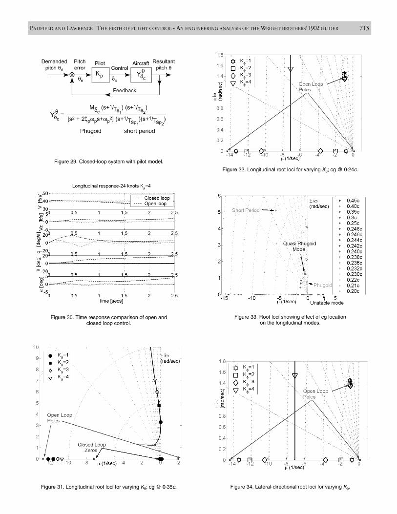
Figure 29. Closed-loop system with pilot model.
Figure 30. Time response comparison of open and closed loop control.
Figure 31. Longitudinal root loci for varying Kθ; cg @ 0⋅35c. Figure 34. Lateral-directional root loci for varying Kφ.
Figure 32. Longitudinal root loci for varying Kθ; cg @ 0⋅24c.
Figure 33. Root loci showing effect of cg location on the longitudinal modes.
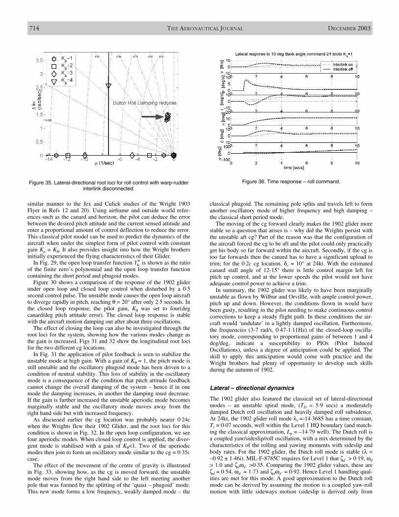
similar manner to the Jex and Culick studies of the Wright 1903Flyer in Refs 12 and 20). Using airframe and outside world refer-ences such as the canard and horizon, the pilot can deduce the errorbetween the desired pitch attitude and the current sensed attitude andenter a proportional amount of control deflection to reduce the error.This classical pilot model can be used to predict the dynamics of theaircraft when under the simplest form of pilot control with constantgain Kp = Kθ. It also provides insight into how the Wright brothersinitially experienced the flying characteristics of their Glider.
In Fig. 29, the open loop transfer function is shown as the ratioof the finite zero’s polynomial and the open loop transfer functioncontaining the short period and phugoid modes.
Figure 30 shows a comparison of the response of the 1902 gliderunder open loop and closed loop control when disturbed by a 0⋅5second control pulse. The unstable mode causes the open loop aircraftto diverge rapidly in pitch, reaching θ = 20° after only 2⋅5 seconds. Inthe closed loop response, the pilot gain, Kθ was set to four(degcanard/deg pitch attitude error). The closed loop response is stablewith the aircraft motion damping out after about three oscillations.
The effect of closing the loop can also be investigated through theroot loci for the system, showing how the various modes change asthe gain is increased. Figs 31 and 32 show the longitudinal root locifor the two different cg locations.
In Fig. 31 the application of pilot feedback is seen to stabilize theunstable mode at high gain. With a gain of Kθ = 1, the pitch mode isstill unstable and the oscillatory phugoid mode has been driven to acondition of neutral stability. This loss of stability in the oscillatorymode is a consequence of the condition that pitch attitude feedbackcannot change the overall damping of the system – hence if in onemode the damping increases, in another the damping must decrease.If the gain is further increased the unstable aperiodic mode becomesmarginally stable and the oscillatory mode moves away from theright hand side but with increased frequency.
As discussed earlier the cg location was probably nearer 0⋅24cwhen the Wrights flew their 1902 Glider, and the root loci for thiscondition is shown in Fig. 32. In the open loop configuration, we seefour aperiodic modes. When closed loop control is applied, the diver-gent mode is stabilised with a gain of Kθ<1. Two of the aperiodicmodes then join to form an oscillatory mode similar to the cg = 0⋅35ccase.
The effect of the movement of the centre of gravity is illustratedin Fig. 33, showing how, as the cg is moved forward, the unstablemode moves from the right hand side to the left meeting anotherpole that was formed by the splitting of the ‘quasi – phugoid’ mode.This new mode forms a low frequency, weakly damped mode – the
classical phugoid. The remaining pole splits and travels left to formanother oscillatory mode of higher frequency and high damping –the classical short period mode.
The moving of the cg forward clearly makes the 1902 glider morestable so a question that arises is – why did the Wrights persist withthe unstable aft cg? Part of the reason was that the configuration ofthe aircraft forced the cg to be aft and the pilot could only practicallyget his body so far forward within the aircraft. Secondly, if the cg istoo far forwards then the canard has to have a significant upload totrim; for the 0⋅2c cg location, δc = 10° at 24kt. With the estimatedcanard stall angle of 12-15° there is little control margin left forpitch up control, and at the lower speeds the pilot would not haveadequate control power to achieve a trim.
In summary, the 1902 glider was likely to have been marginallyunstable as flown by Wilbur and Orvillle, with ample control power,pitch up and down. However, the conditions flown in would havebeen gusty, resulting in the pilot needing to make continuous controlcorrections to keep a steady flight path. In these conditions the air-craft would ‘undulate’ in a lightly damped oscillation. Furthermore,the frequencies (3-7 rad/s, 0⋅47-1⋅11Hz) of the closed-loop oscilla-tory mode, corresponding to proportional gains of between 1 and 4deg/deg, indicate a susceptibility to PIOs (Pilot InducedOscillations), unless a degree of anticipation could be applied. Theskill to apply this anticipation would come with practice and theWright brothers had plenty of opportunity to develop such skillsduring the autumn of 1902.
Lateral – directional dynamics
The 1902 glider also featured the classical set of lateral-directionalmodes – an unstable spiral mode, (TD = 5⋅9 secs) a moderatelydamped Dutch roll oscillation and heavily damped roll subsidence.At 24kt, the 1902 glider roll mode λr =-14⋅3685 has a time constant,Tr = 0⋅07 seconds, well within the Level 1 HQ boundary (and match-ing the classical approximation, Lp = –14⋅79 well). The Dutch roll isa coupled yaw/sideslip/roll oscillation, with a mix determined by thecharacteristics of the rolling and yawing moments with sideslip andbody rates. For the 1902 glider, the Dutch roll mode is stable (λ =–0⋅92 ± 1⋅46i). MIL-F-8785C requires for Level 1 that ζd > 0⋅19, ωd> 1.0 and ζdωd >0⋅35. Comparing the 1902 glider values, these areζd = 0⋅54, ωd = 1⋅73 and ζdωd = 0⋅92. Hence Level 1 handling qual-ities are met for this mode. A good approximation to the Dutch rollmode can be derived by assuming the motion is a coupled yaw-rollmotion with little sideways motion (sideslip is derived only from
714 THE AERONAUTICAL JOURNAL DECEMBER 2003
Figure 35. Lateral-directional root loci for roll control with warp-rudderinterlink disconnected.
Figure 36. Time response – roll command.
cYθ
δ
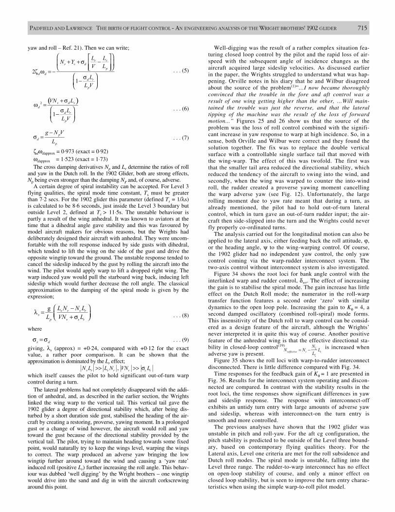
yaw and roll – Ref. 21). Then we can write;
ζdωdapprox = 0⋅973 (exact = 0⋅92)ωdapprox = 1⋅523 (exact = 1⋅73)The cross damping derivatives Np and Lr determine the ratios of roll
and yaw in the Dutch roll. In the 1902 Glider, both are strong effects,Np being even stronger than the damping Nr and, of course, adverse.
A certain degree of spiral instability can be accepted. For Level 3flying qualities, the spiral mode time constant, Ts must be greaterthan 7⋅2 secs. For the 1902 glider this parameter (defined Ts = 1/λs)is calculated to be 8⋅6 seconds, just inside the Level 3 boundary butoutside Level 2, defined at Ts > 11⋅5s. The unstable behaviour ispartly a result of the wing anhedral. It was known to aviators at thetime that a dihedral angle gave stability and this was favoured bymodel aircraft makers for obvious reasons, but the Wrights haddeliberately designed their aircraft with anhedral. They were uncom-fortable with the roll response induced by side gusts with dihedral,which tended to lift the wing on the side of the gust and drive theopposite wingtip toward the ground. The unstable response tended tocancel the sideslip induced by the gust by rolling the aircraft into thewind. The pilot would apply warp to lift a dropped right wing. Thewarp induced yaw would pull the starboard wing back, inducing leftsideslip which would further decrease the roll angle. The classicalapproximation to the damping of the spiral mode is given by theexpression;
where
giving, λs (approx) = +0⋅24, compared with +0⋅12 for the exactvalue, a rather poor comparison. It can be shown that the approximation is dominated by the Lr effect;
which itself causes the pilot to hold significant out-of-turn warpcontrol during a turn.
The lateral problems had not completely disappeared with the addi-tion of anhedral, and, as described in the earlier section, the Wrightslinked the wing warp to the vertical tail. This vertical tail gave the1902 glider a degree of directional stability which, after being dis-turbed by a short duration side gust, stabilised the heading of the air-craft by creating a restoring, proverse, yawing moment. In a prolongedgust or a change of wind however, the aircraft would roll and yawtoward the gust because of the directional stability provided by thevertical tail. The pilot, trying to maintain heading towards some fixedpoint, would naturally try to keep the wings level, warping the wingsto correct. The warp produced an adverse yaw bringing the lowwingtip further around toward the wind and causing a ‘yaw rate’induced roll (positive Lr) further increasing the roll angle. This behav-iour was dubbed ‘well digging’ by the Wright brothers – one wingtipwould drive into the sand and dig in with the aircraft corkscrewingaround this point.
Well-digging was the result of a rather complex situation fea-turing closed loop control by the pilot and the rapid loss of air-speed with the subsequent angle of incidence changes as theaircraft acquired large sideslip velocities. As discussed earlierin the paper, the Wrights struggled to understand what was hap-pening. Orville notes in his diary that he and Wilbur disagreedabout the source of the problem(1)”…I now became thoroughlyconvinced that the trouble in the fore and aft control was aresult of one wing getting higher than the other, …Will main-tained the trouble was just the reverse, and that the lateraltipping of the machine was the result of the loss of forwardmotion...” Figures 25 and 26 show us that the source of theproblem was the loss of roll control combined with the signifi-cant increase in yaw response to warp at high incidence. So, in asense, both Orville and Wilbur were correct and they found thesolution together. The fix was to replace the double verticalsurface with a controllable single surface tail that moved withthe wing-warp. The effect of this was twofold. The first wasthat the smaller tail area reduced the directional stability, whichreduced the tendency of the aircraft to swing into the wind, andsecondly, when the wing was warped to counter the into-windroll, the rudder created a proverse yawing moment cancellingthe warp adverse yaw (see Fig. 12). Unfortunately, the largerolling moment due to yaw rate meant that during a turn, asalready mentioned, the pilot had to hold out-of-turn lateralcontrol, which in turn gave an out-of-turn rudder input; the air-craft then side-slipped into the turn and the Wrights could neverfly properly co-ordinated turns.
The analysis carried out for the longitudinal motion can also beapplied to the lateral axis, either feeding back the roll attitude, ϕ,or the heading angle, ψ to the wing-warping control. Of course,the 1902 glider had no independent yaw control, the only yawcontrol coming via the warp-rudder interconnect system. Thetwo-axis control without interconnect system is also investigated.
Figure 34 shows the root loci for bank angle control with theinterlinked warp and rudder control, δwr. The effect of increasingthe gain is to stabilise the spiral mode. The gain increase has littleeffect on the Dutch Roll mode; the numerator in the roll-warptransfer function features a second order ‘zero’ with similardynamics to the open loop pole. Increasing the gain to Kφ = 4, asecond damped oscillatory (combined roll-spiral) mode forms.This insensitivity of the Dutch roll to warp control can be consid-ered as a design feature of the aircraft, although the Wrights’never interpreted it in quite this way of course. Another positivefeature of the anhredral wing is that the effective directional sta-bility in closed-loop control(19) is increased whenadverse yaw is present.
Figure 35 shows the roll loci with warp-to-rudder interconnectdisconnected. There is little difference compared with Fig. 34.
Time responses for the feedback gain of Kφ = 1 are presented inFig. 36. Results for the interconnect system operating and discon-nected are compared. In contrast with the stability results in theroot loci, the time responses show significant differences in yawand sideslip response. The response with interconnect-offexhibits an untidy turn entry with large amounts of adverse yawand sideslip, whereas with interconnect-on the turn entry issmooth and more controlled.
The previous analyses have shown that the 1902 glider wasunstable in pitch and roll-yaw. For the aft cg configuration, thepitch stability is predicted to be outside of the Level three bound-ary, based on contemporary flying qualities theory. For theLateral axis, Level one criteria are met for the roll subsidence andDutch roll modes. The spiral mode is unstable, falling into theLevel three range. The rudder-to-warp interconnect has no effecton open-loop stability of course, and only a minor effect onclosed loop stability, but is seen to improve the turn entry charac-teristics when using the simple warp-to-roll pilot model.
PADFIELD AND LAWRENCE THE BIRTH OF FLIGHT CONTROL - AN ENGINEERING ANALYSIS OF THE WRIGHT BROTHERS' 1902 GLIDER 715
. . . (5)21
vrr v d
pd d
d r
p
LLN YV L
LL V
+ + σ −
ζ ω = − σ−
. . . (6)( )2
1
v d vd
d r
p
VN L
LL V
+ σω =
σ−
. . . (7)p
dp
g N VL
−σ =
. . . (8)g v r v r
sp v s v
L N N LL VN L
−λ = + σ
. . . (9)s dσ = σ
,v r v r v s vN L L N VN L>> >> σ
veffective v v
NN N L
Lζ
ζ
= −
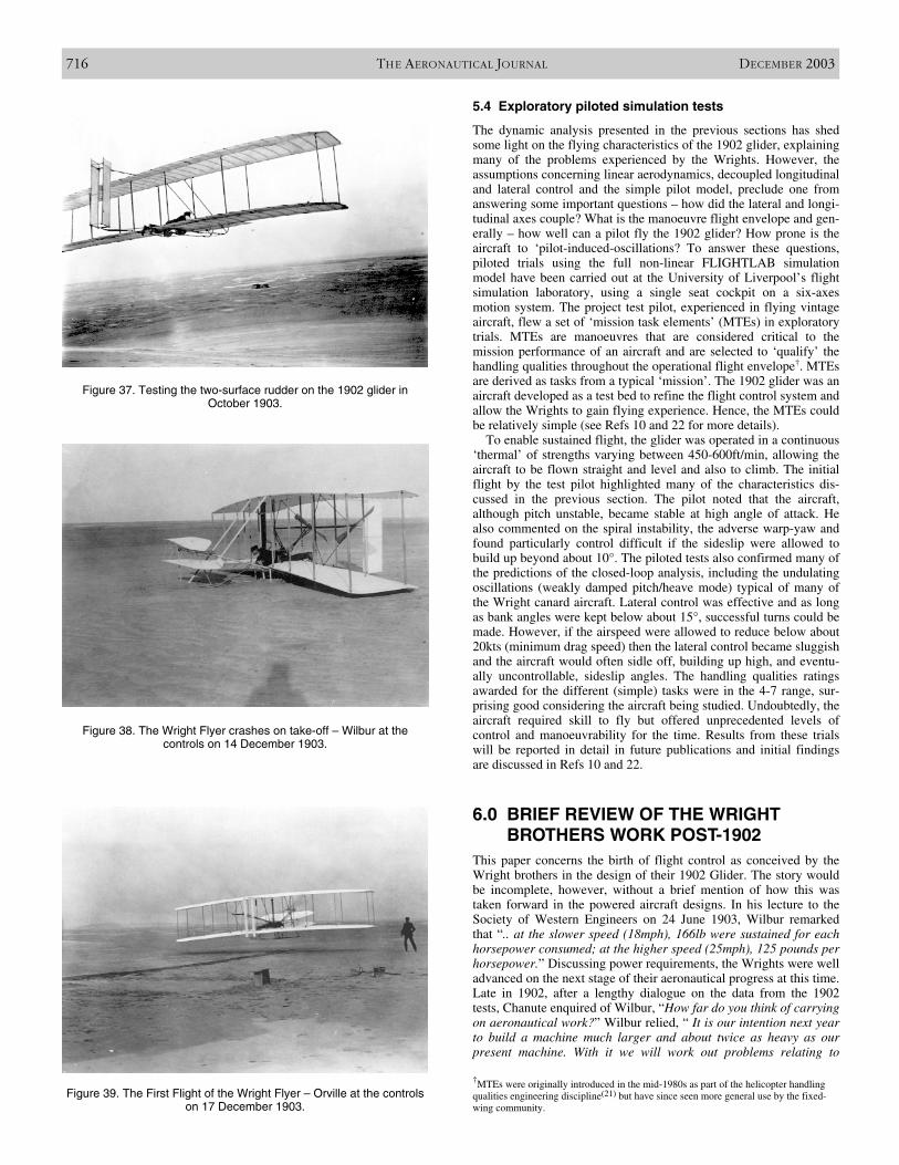
5.4 Exploratory piloted simulation tests
The dynamic analysis presented in the previous sections has shedsome light on the flying characteristics of the 1902 glider, explainingmany of the problems experienced by the Wrights. However, theassumptions concerning linear aerodynamics, decoupled longitudinaland lateral control and the simple pilot model, preclude one fromanswering some important questions – how did the lateral and longi-tudinal axes couple? What is the manoeuvre flight envelope and gen-erally – how well can a pilot fly the 1902 glider? How prone is theaircraft to ‘pilot-induced-oscillations? To answer these questions,piloted trials using the full non-linear FLIGHTLAB simulationmodel have been carried out at the University of Liverpool’s flightsimulation laboratory, using a single seat cockpit on a six-axesmotion system. The project test pilot, experienced in flying vintageaircraft, flew a set of ‘mission task elements’ (MTEs) in exploratorytrials. MTEs are manoeuvres that are considered critical to themission performance of an aircraft and are selected to ‘qualify’ thehandling qualities throughout the operational flight envelope†. MTEsare derived as tasks from a typical ‘mission’. The 1902 glider was anaircraft developed as a test bed to refine the flight control system andallow the Wrights to gain flying experience. Hence, the MTEs couldbe relatively simple (see Refs 10 and 22 for more details).
To enable sustained flight, the glider was operated in a continuous‘thermal’ of strengths varying between 450-600ft/min, allowing theaircraft to be flown straight and level and also to climb. The initialflight by the test pilot highlighted many of the characteristics dis-cussed in the previous section. The pilot noted that the aircraft,although pitch unstable, became stable at high angle of attack. Healso commented on the spiral instability, the adverse warp-yaw andfound particularly control difficult if the sideslip were allowed tobuild up beyond about 10°. The piloted tests also confirmed many ofthe predictions of the closed-loop analysis, including the undulatingoscillations (weakly damped pitch/heave mode) typical of many ofthe Wright canard aircraft. Lateral control was effective and as longas bank angles were kept below about 15°, successful turns could bemade. However, if the airspeed were allowed to reduce below about20kts (minimum drag speed) then the lateral control became sluggishand the aircraft would often sidle off, building up high, and eventu-ally uncontrollable, sideslip angles. The handling qualities ratingsawarded for the different (simple) tasks were in the 4-7 range, sur-prising good considering the aircraft being studied. Undoubtedly, theaircraft required skill to fly but offered unprecedented levels ofcontrol and manoeuvrability for the time. Results from these trialswill be reported in detail in future publications and initial findingsare discussed in Refs 10 and 22.
6.0 BRIEF REVIEW OF THE WRIGHTBROTHERS WORK POST-1902
This paper concerns the birth of flight control as conceived by theWright brothers in the design of their 1902 Glider. The story wouldbe incomplete, however, without a brief mention of how this wastaken forward in the powered aircraft designs. In his lecture to theSociety of Western Engineers on 24 June 1903, Wilbur remarkedthat “.. at the slower speed (18mph), 166lb were sustained for eachhorsepower consumed; at the higher speed (25mph), 125 pounds perhorsepower.” Discussing power requirements, the Wrights were welladvanced on the next stage of their aeronautical progress at this time.Late in 1902, after a lengthy dialogue on the data from the 1902tests, Chanute enquired of Wilbur, “How far do you think of carryingon aeronautical work?” Wilbur relied, “ It is our intention next yearto build a machine much larger and about twice as heavy as ourpresent machine. With it we will work out problems relating to
716 THE AERONAUTICAL JOURNAL DECEMBER 2003
Figure 37. Testing the two-surface rudder on the 1902 glider in October 1903.
Figure 38. The Wright Flyer crashes on take-off – Wilbur at the controls on 14 December 1903.
Figure 39. The First Flight of the Wright Flyer – Orville at the controlson 17 December 1903.
†MTEs were originally introduced in the mid-1980s as part of the helicopter handlingqualities engineering discipline(21) but have since seen more general use by the fixed-wing community.
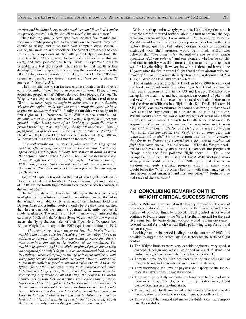
starting and handling heavy weight machines, and if we find it undersatisfactory control in flight, we will proceed to mount a motor.”
Their thinking quickly developed over the next few months and,with no suitable powerplant to be found on the market, they pro-ceeded to design and build their own complete drive system –engine, transmission and propellers. The Wrights designed and con-structed the components of their 4th piloted flying machine, theFlyer (see Ref. 23 for a comprehensive technical review of this air-craft), and they journeyed to Kitty Hawk in September 1903 toassemble and test the aircraft. They spent the first month furtherdeveloping their flying skills and refining the control system on the1902 Glider; Orville recorded in his diary on 26 October, “We suc-ceeded in breaking our former record six times out of about 20attempts”(1) (see Fig. 37).
Their first attempts to run the new engine mounted on the Flyer inearly November failed due to excessive vibration. Then, on twooccasions, propeller shaft failures delayed their progress further. TheWrights were very concerned that the weight had increased to over700lb “ the thrust required might be 100lb, and we got to doubtingwhether the engine would have the power, using the gears we have,to give the necessary thrust”(1). Finally the machine was ready for itsfirst flight on 14 December. With Wilbur at the controls, “themachine turned up in front and rose to a height of about 15 feet fromground… After losing most of its headway it gradually sank toground turned up at an angle of probably 20º incidence….Time offlight from end of track was 3½ seconds, for a distance of 105ft.”(1).On its first flight, The Flyer had crashed on take off (Fig. 38) andWilbur stated in a letter to his father on the same day,
“the real trouble was an error in judgement, in turning up toosuddenly after leaving the track, and as the machine had barelyspeed enough for support already, this slowed in down so muchthat before I could correct the error, the machine began to comedown, though turned up at a big angle.” Characteristically,Wilbur was first to admit his mistake and it took two days to repairthe damage. They took the machine out again on the morning of17 December.
Figure 39 captures take-off on the first of four flights made on 17December Orville flew for about 12secs, covering a ground distanceof 120ft. On the fourth flight Wilbur flew for 59 seconds covering adistance of 852ft(1).
The four flights on 17 December 1903 gave the brothers a verybrief glimpse of the future. It would take another nine months beforethe Wrights were able to fly a circuit of the Huffman field nearDayton, Ohio and a further twelve months before they were satisfiedthat they understood the handling qualities sufficiently well to flysafely at altitude. The autumn of 1905 in many ways mirrored theautumn of 1902, with the Wrights flying extensively for two weeks tomaster the flying characteristics of their Flyer No 3. To quote fromWilbur Wrights’ summary of the 1905 experiments, written in 1912.
“…The trouble was really due to the fact that in circling, themachine has to carry the load resulting from centrifugal force, inaddition to its own weight, since the actual pressure that the airmust sustain is that due to the resultant of the two forces. Themachine in question had but a slight surplus of power above whatwas required for straight flight, and as the additional load, causedby circling, increased rapidly as the circle became smaller, a limitwas finally reached beyond which the machine was no longer ableto maintain sufficient speed to sustain itself in the air. And as thelifting effect of the inner wing, owing to its reduced speed, coun-terbalanced a large part of the increased lift resulting from thegreater angle of incidence on that wing, the response to lateralcontrol was so slow that the machine sank to the ground, usuallybefore it had been brought back to the level again. In other wordsthe machine was in what has come to be known as a stalled condi-tion…. When we had discovered the real nature of the trouble, andknew that it could always be remedied by tilting the machineforward a little, so that its flying speed would be restored, we feltthat we were ready to place flying machines on the market.”
Wilbur, perhaps unknowingly, was also highlighting that a pitchunstable aircraft required forward stick in a turn to counter the neg-ative manoeuvre margin. From autumn 1902 to autumn 1905 theWrights would work hard to design a powered machine with satis-factory flying qualities, but without design criteria or supportinganalytical tools their progress would be limited. Wilbur alsobelieved that “The remedy for the difficulty lies in more skilfuloperation of the aeroplanes” and one wonders whether he consid-ered that instability was the natural condition of flying, much as itwas for bicycle riding. However, he was not alone and it would be10 years after the first powered flight that the first aircraft with sat-isfactory all-round inherent stability flew (the Farnborough BE2 in1913, a Green-de Havilland design – Ref. 2).
The Wrights returned to Kitty Hawk in May 1908 to carry outthe final design refinements to the Flyer No 3 and prepare fortheir aerial demonstrations in the US and Europe. The pilot nowsat up in the machine, and had independent control of pitch, rolland yaw. Flights with a passenger on board were also being madeand the time of Wilbur’s last flight at the Kill Devil Hills (on 14May 1908) was seven minutes 29 seconds, covering a distance ofover 8km; the flight ended in a crash! In the months to come,Wilbur would amaze the world with his feats of aerial navigationin the skies over France. He wrote to Orville from Le Mans on 15August(1), “The newspapers and the French aviators nearly wentwild with excitement. Blériot and Delagrange were so excitedthey could scarcely speak, and Kapferer could only gasp andcould not talk at all.” Bleriot was quoted as saying, “I considerthat for us in France and everywhere a new era in mechanicalflight has commenced…it is marvelous.” What the Wright broth-ers had achieved three years earlier far exceeded the progress inEurope since the first powered flight there in 1906 – theEuropeans could only fly in straight lines! With Wilbur demon-strating what could be done, after 1908 the rate of progress inaviation was quite startling; progress which, in many ways,would leave the Wright brothers behind – with their legacy as thefirst aeronautical engineers and first test pilots(24). Perhaps theyhad reached their horizon?
7.0 CONCLUDING REMARKS ON THEWRIGHT CRITICAL SUCCESS FACTORS
October 1902 was a watershed in the history of aviation. The use ofthree-axis flight control paved the way for the invention and devel-opment of powered flight to proceed. Flight control issues wouldcontinue to feature large in the Wright brothers’ aircraft for the nextfive years but the basic design concept would remain the same –forward canard for pitch/vertical flight path, wing warp for roll andrudder for yaw.
Looking back to the period leading up to the autumn of 1902, it ispossible to suggest the critical success factors for the birth of flightcontrol1) The Wright brothers were very capable engineers, very good at
conceptual design and what is described as visual thinking, andparticularly good at being able to stay focused on goals,
2) They had developed a high proficiency in the practical skills ofmanufacturing and a knowledge in the use of materials,
3) They understood the laws of physics and aspects of the mathe-matical analysis of mechanical systems,
4) They were powerfully motivated to learn how to fly, and madethousands of gliding flights to develop performance, flightcontrol concepts and piloting skills,
5) They designed, built and tested exhaustively (aerofoil aerody-namics, structures, control systems, engines, propellers etc.),
6) They realised that control and manoeuvrability were more impor-tant than stability,
PADFIELD AND LAWRENCE THE BIRTH OF FLIGHT CONTROL - AN ENGINEERING ANALYSIS OF THE WRIGHT BROTHERS' 1902 GLIDER 717
7) They took what is nowadays referred to as a systems approach totheir work – understanding that an aeroplane is a technologicalsystem of discrete elements, including the pilot, all of which had to besuccessfully designed and integrated to achieve success. Within thiscontext their continuity of design was also important, solving prob-lems in an evolutionary fashion,
8) They were a team, sharing responsibilities, sharing a common vision.Other success factors can be mentioned, including the Wrights choice
of test site, their willingness and (financial) ability to undertake annualcampaigns, but from the above list, factor number six was particularlyimportant. The aft cg and canard control conferred the 1902 Glider withgreater control power than an equivalent tailed aircraft, crucial at the lowspeeds flown by the Wrights; the manoeuvrability was further enhancedby the negative static margin (and for the furthest aft case, negativemanoeuvre margin). The canard also provided a powerful attitude refer-ence and protection during ‘heavy’ landings or crashes. Of critical impor-tance to the Wrights, the wing design gave safe stall characteristics. Thewing anhedral increased the effective roll control power and closed-loopdirectional stability and the warp-rudder control interlink assisted turnentry.
All of the success factors listed above are considered important, and itis hard to imagine the invention of powered flight being achieved quiteso rapidly, or without more serious mishaps, in the early 1900s withoutthe Wright Brothers and their pursuit of excellence. In the years to come,many chief designers would be noted for similar attributes. Nowadays,however, although University degree and Industry training programmesencourage innovation, and attempt to instill a broad appreciation of thetechnologies involved and an ethos of engineering excellence, few prac-ticing engineers have the opportunity to work across such a broad frontand put ideas into practice quite so readily as the Wrights did. Perhapsthis is a shortcoming of our current systems and the centenary ofpowered flight provides a good opportunity to reflect on this. For theWrights, almost at every turn, ‘necessity was the mother of invention’.The desire to fly and ultimately to invent the practical aeroplane was thespur to their relentless pursuit of the mastery of flight control. Perhapsone of the challenges for 21st century aerospace engineering is to under-stand how to enable innovation to flourish amidst so much ‘advanced’technology.
Wilbur and Orville can also teach us something about patience. Theyfirst applied to patent their three-axis flight control system in March1903. It was rejected by the US Patent Office, who claimed the descrip-tion was “vague and indefinite” and “incapable of performing itsintended function”(4). The patent was eventually granted in the US inMay 1906, two years after Great Britain and France had approved theapplication.
This paper has presented the story of the birth of flight control as fea-tured in the Wrights’ 1902 Glider, and appraised in the Liverpool WrightProject. High-fidelity simulations of the 1901 and 1902 gliders and the1903 Flyer are currently operational on the motion simulator at Liverpooland work is underway to create a simulation of the 1905 design, the firstpractical aircraft. This ongoing research is supported by a RoyalAeronautical Society Centenary Award. Future publications will reportthe continuing progress.
ACKNOWLEDGEMENTSThe research reported in this paper was partly funded by an UK EPSRCDoctoral Training award for the second author. Financial support fromThe Friends of The University of Liverpool, enabling the wind-tunneltesting to be conducted, is greatly appreciated and acknowledged. Theauthors would like to thank Peter Jakab and Tom Crouch, AeronauticsCurators at the National Air and Space Museum, Washington DC, forfruitful discussions and for the opportunity to work with them in thisCentenary period. The authors are also particularly grateful to ProfessorNorman Wood at the University of Manchester and the team at FlowScience for the use of the Goldstein wind-tunnel facilities. The projectTest Pilot, Roger ‘Dodge’ Bailey from Cranfield University/Shuttleworth
718 THE AERONAUTICAL JOURNAL DECEMBER 2003
Collection has worked with the Liverpool team during the project; hisinsight into handling qualities from the pilot’s perspective has provedinvaluable. Most of the photographs taken during the Wrights’ test cam-paigns and presented in this paper are the property of the US Library ofCongress who are gratefully acknowledged. Figure 10(b) and Figs 13(a),13(b) and 13(d) are the property of Wright State University who are alsoacknowledged. The Sketches in Figs 3, 4 and 10 were taken from Ref 25.
REFERENCES1. MCFARLAND, M.W. (Ed), The Papers of Wilbur and Orville Wright, includ-
ing the Chanute-Wright Letters and other papers of Octave Chanute, 1953,McGraw Hill, New York.
2. GIBBS-SMITH, C.H. The Aeroplane; An historical survey of its origins anddevelopment, 1960, Her Majesty’s Stationery Office, London.
3. JAKAB, P.L. Visions of a Flying Machine, The Wright Brothers and theProcess of Invention, 1990, Smithsonian Institution Press.
4. CROUCH, T.D. The Bishop’s Boys, A Life of Wilbur and Orville Wright,1989, W.W. Norton, New York.
5. CULICK, F.E.C. What the Wright brothers did and did not understand aboutflight mechanics – in modern terms, AIAA-2001-3385, 37thAIAA/ASME/SAE/ASEE Joint Propulsion Conference and Exhibit, July2001 Salt Lake City, Utah.
6. BRYAN, G.H. and WILLIAMS, W.E. The longitudinal stability of gliders, June1903, Proc Royal Society of London.
7. LILIENTHAL, O. Der Vogelflug als Grundlage der Fliegekunst. Berlin: R.Gaertners Verlagsbuchhandlung (Birdflight as the Basis of Aviation,American Aeronautical Archives, Markowski International Publishers,2001).
8. ANDERSON, J.D. A History of Aerodynamics and its Impact on FlyingMachines, 1998, Cambridge University Press.
9. PHILLIPS, W.H. Flying qualities from early airplanes to the space shuttle,Dryden Lectureship in Research, AIAA 26th Aerospace Sciences Meeting,Reno Jan 1988, AIAA J Guidance and Control, July-August 1989, 12, (4).
10. LAWRENCE, B. and PADFIELD, G.D. A handling qualities analysis of theWright brothers 1902 Glider, AIAA Atmospheric Flight MechanicsConference, Austin, Texas, 11-14 August, 2003.
11. MCCORMICK, B.W. Aerodynamics, Aeronautics, and Flight Mechanics,1995, 2nd ed, John Wiley and Sons, New York, 1995.
12. JEX, H.R. and CULICK, F.E.C. Flight control dynamics of the 1903 WrightFlyer, 1985, AIAA Paper, p 534-548.
13. PADFIELD, G.D and WHITE, M.D. Flight simulation in academia;HELIFLIGHT in its first year of operation, Aeronaut J, October 2003, 107,(1076), (also in ‘The challenge of realistic rotorcraft simulation’, RAeSConference, London, Nov 2001).
14. KOCHERSBERGER, K., SANDUSKY R., HYDE K., ASH R., BRITCHER C. andLANDMAN, D. An evaluation of the Wright 1901 Glider using full scale windtunnel data, AIAA Aerospace Sciences Meeting & Exhibit, 40th, Reno, NV,2002.
15. ETKIN, B. Dynamics of Atmospheric Flight, 1972, John Wiley and Sons,New York.
16. Anon MIL-F-8785C, Military Specification Flying Qualities of PilotedAirplanes. U.S. Department of Defense, 1980.
17. Anon MIL-HDBK-1797, Flying Qualities of Piloted Aircraft, USDepartment of Defense, 1997.
18. COOPER, G. E., HARPER, R.P. The use of pilot rating in the evaluation of air-craft handling qualities and pilot evaluation, NASA TN D-5153, April 1969
19. MILNE, R.D. and PADFIELD, G.D. The Strongly controlled aircraft, AeronautQ, May 1971, XXII, pp 146-168.
20. CULICK, F.E.C. and JEX, H.R. Aerodynamics, stability and control of the1903 Wright Flyer, The Wright Flyer, an engineering perspective, NationalAir and Space Museum, Washington DC, 1987.
21. PADFIELD, G.D. Helicopter Flight Dynamics, 1996, Blackwell Science,Oxford.
22. LAWRENCE, B. and PADFIELD, G.D. Flight testing simulations of the Wright1902 Glider and 1903 Flyer, 34th Annual International Symposium of theSFTE, Portsmouth, Va, September 2003.
23. WOLKO, H.S. (Ed) The Wright Flyer; an engineering perspective, 1987,Smithsonian Institution.
24. CULICK, F.E.C. Wright brothers: first aeronautical engineers and test pilots,Sept 2001, 45th Annual Symposium of the Society of Experimental TestPilots, Los Angeles, California.
25. CULICK, F.E.C., The origins of the first powered, man-carrying airplane,December 1979, Scientific American.