Embed Size (px)
Citation preview

THE BIOMECHANICAL ANALYSIS OF THE HAND IN RHEUMATOID
ARTHRITIS PATIENTS WITH MCP ARTHROPLASTY
Louise Elizabeth LesterMRes Biomaterials
January 2009
Department of Metallurgy and Materials amp Department of Mechanical and Manufacturing EngineeringThe University of Birmingham
University of Birmingham Research Archive
e-theses repository This unpublished thesisdissertation is copyright of the author andor third parties The intellectual property rights of the author or third parties in respect of this work are as defined by The Copyright Designs and Patents Act 1988 or as modified by any successor legislation Any use made of information contained in this thesisdissertation must be in accordance with that legislation and must be properly acknowledged Further distribution or reproduction in any format is prohibited without the permission of the copyright holder
ABSTRACT
Rheumatoid arthritis (RA) is a chronic inflammatory disease causing extreme
deformity pain and swelling of joints severely affecting quality of life Arthroplasty has had
considerable success in larger joints such as the hip The most frequently used artificial finger
joints rely on a silicone elastomer component for their flexibility However success of these
implants has been mixed with fracture rates for the elastomer component reported to be up to
82 It is currently unknown why fracture of the elastomer occurs so frequently Motion
analysis was used to determine range of motion (ROM) of the metacarpophalangeal (MCP)
joints in patients with rheumatoid arthritis both without and with arthroplasty to determine
how the procedure affects motion of the joint A 12 camera motion capture system was used
to capture hand kinematic data Preliminary experiments determined the best positions for
reflective markers for measuring motion Subjects consisted of a control population (20) and a
patient population (10 without surgery and 10 with) Data were processed to give maximum
minimum and ROMs of flexionextension and abductionadduction at all MCPs during four
movements pinch grip key grip fist clench and hand spread Results showed ROM was
decreased by ageing further by RA and further again by replacement surgery MCP surgery
patients produced significantly lower ROMs than all other groups suggesting the implants
may not restore movement
ACKNOWLEDGEMENTS
I would like to start by thanking everyone at MARRC for all their help over the last eighteen
months to make sure I completed both my testing and thesis A special thanks to Mr Joe
Bevin for all his hard work time effort and extreme patience with me teaching me the ins
and outs of Vicon and generally being a life saver
Secondly my thanks go to the team from Worcester acute NHS trust Professor Ashok Rai Dr
Arafa and Hellen Whalley for all their help in particular recruiting patients as quickly as
possible Many thanks to Ashok for all his time and help with everything including the
lengthy ethics submission and enabling me to sit in on his clinics
Finally I would like to thank my supervisors Professor David Hukins and Dr Duncan
Shepherd for their valuable advice continued support and encouragement throughout without
them I am sure this thesis would not exist
TABLE OF CONTENTS
1 INTRODUCTIONhelliphelliphelliphelliphelliphelliphelliphelliphelliphelliphelliphelliphelliphelliphelliphelliphelliphelliphelliphelliphelliphelliphelliphelliphellip1
2 BACKGROUND INFORMATIONhelliphelliphelliphelliphelliphelliphelliphelliphelliphelliphelliphelliphelliphelliphelliphelliphelliphellip3
21 Rheumatoid Arthritishelliphelliphelliphelliphelliphelliphelliphelliphelliphelliphelliphelliphelliphelliphelliphelliphelliphelliphelliphellip3
211 Introductionhelliphelliphelliphelliphelliphelliphelliphelliphelliphelliphelliphelliphelliphelliphelliphelliphelliphelliphelliphellip3
212 Prevalencehelliphelliphelliphelliphelliphelliphelliphelliphelliphelliphelliphelliphelliphelliphelliphelliphelliphelliphelliphelliphellip3
213 Etiologyhelliphelliphelliphelliphelliphelliphelliphelliphelliphelliphelliphelliphelliphelliphelliphelliphelliphelliphelliphelliphelliphellip4
214 Symptoms and classificationhelliphelliphelliphelliphelliphelliphelliphelliphelliphelliphelliphelliphelliphellip4
215 Pathogenesishelliphelliphelliphelliphelliphelliphelliphelliphelliphelliphelliphelliphelliphelliphelliphelliphelliphelliphelliphellip5
216 Treatmenthelliphelliphelliphelliphelliphelliphelliphelliphelliphelliphelliphelliphelliphelliphelliphelliphelliphelliphelliphelliphellip7
22 Finger arthroplastyhelliphelliphelliphelliphelliphelliphelliphelliphelliphelliphelliphelliphelliphelliphelliphelliphelliphelliphelliphelliphellip9
221 Introductionhelliphelliphelliphelliphelliphelliphelliphelliphelliphelliphelliphelliphelliphelliphelliphelliphelliphelliphelliphellip9
222 Hingedhelliphelliphelliphelliphelliphelliphelliphelliphelliphelliphelliphelliphelliphelliphelliphelliphelliphelliphelliphelliphelliphellip9
223 Flexiblehelliphelliphelliphelliphelliphelliphelliphelliphelliphelliphelliphelliphelliphelliphelliphelliphelliphelliphelliphelliphellip12
224 3rd generationhelliphelliphelliphelliphelliphelliphelliphelliphelliphelliphelliphelliphelliphelliphelliphelliphelliphellip15
225 Complications helliphelliphelliphelliphelliphelliphelliphelliphelliphelliphelliphelliphelliphelliphelliphelliphelliphelliphellip16
23 Material properties of siliconehelliphelliphelliphelliphelliphelliphelliphelliphelliphelliphelliphelliphelliphelliphelliphellip19
231 Introductionhelliphelliphelliphelliphelliphelliphelliphelliphelliphelliphelliphelliphelliphelliphelliphelliphelliphelliphelliphellip19
232 Structurehelliphelliphelliphelliphelliphelliphelliphelliphelliphelliphelliphelliphelliphelliphelliphelliphelliphelliphelliphelliphellip19
233 Propertieshelliphelliphelliphelliphelliphelliphelliphelliphelliphelliphelliphelliphelliphelliphelliphelliphelliphelliphelliphelliphellip19
234 Failurehelliphelliphelliphelliphelliphelliphelliphelliphelliphelliphelliphelliphelliphelliphelliphelliphelliphelliphelliphelliphelliphellip20
24 Methods to asses hand movementhelliphelliphelliphelliphelliphelliphelliphelliphelliphelliphelliphelliphelliphelliphellip22
241 Introduction helliphelliphelliphelliphelliphelliphelliphelliphelliphelliphelliphelliphelliphelliphelliphelliphelliphelliphelliphellip22
242 Goniometerhelliphelliphelliphelliphelliphelliphelliphelliphelliphelliphelliphelliphelliphelliphelliphelliphelliphelliphelliphellip22
243 Glove helliphelliphelliphelliphelliphelliphelliphelliphelliphelliphelliphelliphelliphelliphelliphelliphelliphelliphelliphelliphelliphellip23
244 Motion analysishelliphelliphelliphelliphelliphelliphelliphelliphelliphelliphelliphelliphelliphelliphelliphelliphelliphelliphellip24
245 Marker setshelliphelliphelliphelliphelliphelliphelliphelliphelliphelliphelliphelliphelliphelliphelliphelliphelliphelliphelliphellip24
3 EXPERIMENTAL METHODShelliphelliphelliphelliphelliphelliphelliphelliphelliphelliphelliphelliphelliphelliphelliphelliphelliphelliphellip28
31 Ethical considerationshelliphelliphelliphelliphelliphelliphelliphelliphelliphelliphelliphelliphelliphelliphelliphelliphellip28
32 Subjects helliphelliphelliphelliphelliphelliphelliphelliphelliphelliphelliphelliphelliphelliphelliphelliphelliphelliphelliphelliphelliphellip28
33 Motion analysishelliphelliphelliphelliphelliphelliphelliphelliphelliphelliphelliphelliphelliphelliphelliphelliphelliphelliphellip30
34 Trials helliphelliphelliphelliphelliphelliphelliphelliphelliphelliphelliphelliphelliphelliphelliphelliphelliphelliphelliphelliphelliphelliphellip33
35 Analysis helliphelliphelliphelliphelliphelliphelliphelliphelliphelliphelliphelliphelliphelliphelliphelliphelliphelliphelliphelliphellip34
36 Statistical analysishelliphelliphelliphelliphelliphelliphelliphelliphelliphelliphelliphelliphelliphelliphelliphelliphelliphellip35
4 RESULTS helliphelliphelliphelliphelliphelliphelliphelliphelliphelliphelliphelliphelliphelliphelliphelliphelliphelliphelliphelliphelliphelliphelliphelliphelliphelliphellip36
41 Introductionhelliphelliphelliphelliphelliphelliphelliphelliphelliphelliphelliphelliphelliphelliphelliphelliphelliphelliphelliphelliphelliphelliphelliphellip36
42 Pinchhelliphelliphelliphelliphelliphelliphelliphelliphelliphelliphelliphelliphelliphelliphelliphelliphelliphelliphelliphelliphelliphelliphelliphelliphelliphelliphellip36
43 Keyhelliphelliphelliphelliphelliphelliphelliphelliphelliphelliphelliphelliphelliphelliphelliphelliphelliphelliphelliphelliphelliphelliphelliphelliphelliphelliphellip37
44 Fisthelliphelliphelliphelliphelliphelliphelliphelliphelliphelliphelliphelliphelliphelliphelliphelliphelliphelliphelliphelliphelliphelliphelliphelliphelliphelliphellip38
45 Spread helliphelliphelliphelliphelliphelliphelliphelliphelliphelliphelliphelliphelliphelliphelliphelliphelliphelliphelliphelliphelliphelliphelliphelliphelliphellip39
46 patient feedbackhelliphelliphelliphelliphelliphelliphelliphelliphelliphelliphelliphelliphelliphelliphelliphelliphelliphelliphelliphelliphellip44
5 DISCUSSIONhelliphelliphelliphelliphelliphelliphelliphelliphelliphelliphelliphelliphelliphelliphelliphelliphelliphelliphelliphelliphelliphelliphelliphelliphelliphellip45
51 Introductionhelliphelliphelliphelliphelliphelliphelliphelliphelliphelliphelliphelliphelliphelliphelliphelliphelliphelliphelliphelliphelliphelliphelliphellip45
52 Control populationhelliphelliphelliphelliphelliphelliphelliphelliphelliphelliphelliphelliphelliphelliphelliphelliphelliphelliphelliphelliphellip45
53 Rheumatoid patientshelliphelliphelliphelliphelliphelliphelliphelliphelliphelliphelliphelliphelliphelliphelliphelliphelliphelliphelliphellip47
54 MCP replacement patientshelliphelliphelliphelliphelliphelliphelliphelliphelliphelliphelliphelliphelliphelliphelliphelliphelliphellip48
55 Rotationhelliphelliphelliphelliphelliphelliphelliphelliphelliphelliphelliphelliphelliphelliphelliphelliphelliphelliphelliphelliphelliphelliphelliphelliphellip50
56 Forces helliphelliphelliphelliphelliphelliphelliphelliphelliphelliphelliphelliphelliphelliphelliphelliphelliphelliphelliphelliphelliphelliphelliphelliphelliphellip50
57 Mechanical testshelliphelliphelliphelliphelliphelliphelliphelliphelliphelliphelliphelliphelliphelliphelliphelliphelliphelliphelliphelliphelliphellip51
6 CONCLUSIONShelliphelliphelliphelliphelliphelliphelliphelliphelliphelliphelliphelliphelliphelliphelliphelliphelliphelliphelliphelliphelliphelliphelliphelliphellip52
7 APPENDICEShelliphelliphelliphelliphelliphelliphelliphelliphelliphelliphelliphelliphelliphelliphelliphelliphelliphelliphelliphelliphelliphelliphelliphelliphelliphellip53
8 REFERENCEShelliphelliphelliphelliphelliphelliphelliphelliphelliphelliphelliphelliphelliphelliphelliphelliphelliphelliphelliphelliphelliphelliphelliphelliphellip130
1 INTRODUCTION
The crippling joint disease of rheumatoid arthritis often affects the wrist and hand
causing significant inflammation deformity pain and loss of function Treatment can involve
arthrodesis where articular cartilage and soft tissue are removed resulting in one solid bony
mass This procedure is successful in removing pain however it causes loss of movement
and therefore limits hand capabilities considerably The other option is arthroplasty where a
replacement is implanted so movement and function are still possible
However the success of these implants has been mixed and fracture rates have been
reported anywhere from 0-82 Goldfarb and Stern (2003) evaluated 208 arthroplasties an
average of 14 years postoperatively 63 were broken with an additional 22 deformed
Kay et al (1978) report the highest fracture rate of 82 in Swanson prostheses followed for
5 years Of 34 joint replacements 17 were definitely fractured with 11 probable cases After
fracture the implant may not support repetitive loading or movements so may not function as
well and can cause further pain and swelling Revision operations are possible but are an
obvious unwanted complication and more difficult than the initial implantation Therefore
finger implants need to be improved to prevent fracture occurring so frequently or at least
extend the life span of the prostheses
Clues as to why implants are fracturing in such a manner could be provided by
determining the movements that occur at the hand joints It has been suggested that failure of
arthroplasties may be due to twisting and turning forces at finger joints experienced in
everyday activities such as opening containers getting dressed grasping a pen and many
more Motion analysis enables the most accurate and complete analysis of movement but
current marker sets may be too simple and a more complex model may allow a more detailed
understanding of the movement of finger and wrist joints Furthermore limited detailed
research using motion analysis currently exists on not only rheumatoid hands but also on
normal hand movement
Therefore the aim of this project is to accurately measure movement at the
metacarpophalangeal (MCP) joint the most commonly affected in RA tAnd thereforehereby
also attempting to gain a more detailed understanding of finger movement in both ldquonormalrdquo
control subjects and arthritic patients It is not realistic to attempt to give patients a range
equivalent to non diseased hands and neither is it necessary What needs to be determined is
what functional range of movement is needed to improve the quality of life
1
Understanding the movements hands are subjected to in everyday life more accurately and
also investigating what degree of movement might be needed should help substantially when
designing new prostheses
The project will initially focus on determining if a new complex hand marker model is
possible or necessary to understand hand movement further This new marker system is
intended for use when testing normal subjects in several simple hand movement tasks and to
study the effect of ageing The same marker set and tasks will then be used to test patients
with rheumatoid arthritis and also those who have had MCP replacement surgery to
investigate any differences between the movements possible The main outcomes are
therefore (i) the creation of a new more accurate marker set and (ii) determining average
range of hand movement in a normal population those with rheumatoid arthritis and patients
who have had replacement surgery
2
2 BACKGROUND INFORMATION
21 Rheumatoid Arthritis
211 Introduction
Arthritis is a crippling joint disease with unknown cause It affects millions of people
worldwide causing sufferers extreme pain and loss of joint movement and function With no
cure available arthritis patients experience many difficulties consequently quality of life can
be affected considerably
Rheumatoid arthritis (RA) is a chronic inflammatory disease with the primary
manifestation in the synovium and so can affect any synovial joint but most commonly the
hands and feet (Grassi et al 1998) Dramatic swelling and distortion of joints is observed
with tenderness pain and increased temperature at these locations (Lee ampWeinblatt 2001)
These symptoms cause not only great discomfort but also loss of movement at joints
therefore restricting ability to perform everyday tasks and limiting quality of life Loss of job
can cause further problems with a considerable percentage of sufferers becoming disabled
and unable to work (Sokka 2003) This work disability results in loss of income and when
coupled with the medical costs of the disease can lead to financial difficulty Life span of
those with RA is shortened from 3-18 years depending on disease severity and age of onset
(Alamanos ampDrosos 2005)
212 Prevalence
Rheumatoid arthritis affects between 05-10 of people worldwide (Silman
ampPearson 2002) However the occurrence of the disease ranges between different countries
quite drastically (McCarty ampKoopman 1993) In the UK adult population in 2000 it was
estimated that 386600 cases existed (Symmons et al 2002) RA prevalence increases with
age (Lee ampWeinblatt 2001) with the peak onset occurring between 40-60 years of age
Interestingly in all populations and ages women are reported to be 2-3 times more likely to
develop RA (Symmons et al 2002)
3
213 Etiology
The cause of RA is currently unknown Many possibilities have been investigated
including occupational geographical metabolic nutritional genetic and psychosocial factors
(Alamanos ampDrosos 2005) Current consensus is that RA is a multifactorial disease and due
to an interaction between environmental and genetic factors Other factors involved include
ethnicity the role of hormones (Hazes ampVan Zeben 1991) and smoking (Sagg et al 1997)
Genetic factors are among the most popular of possibilities with first degree relatives and
siblings of severe RA patients at a greater risk of developing the disease themselves
(Deighton et al 1992) Furthermore twin studies provide additional evidence reporting that if
one twin has RA a monozygotic twin has a 154 chance of developing the disease compared
with only a 36 likelihood if the twin is dizygotic (Silman et al 1993) Rheumatoid arthritis
development is associated with the class II major histocompatibility complex (MHC) in
particular the human leukocyte antigen-D (HLA-D) region Strong links have been
continuously publicized with the HLA-DR4 epitope (Olsen 1988) Much research has been
conducted to date on the role of genetics in RA with the ldquoshared epitoperdquo theory a popular
suggestion (Morel et al 1990) It is clear from the research that there is a significant risk to
individuals possessing certain gene epitopes or regions The exact region or sequence is still
being investigated and may still only be the cause in some cases or populations Other
possible causes need to still be considered
214 Symptoms and classification
Symptoms of RA include pain and stiffness around the joint often initially in only one
joint but as the disease develops it begins to affect multiple joints (Rindfleisch ampMuller
2005) The bodyrsquos immune system begins to attack the healthy joints leading to inflammation
of joint linings and considerable swelling and pain Fever weight loss fatigue and anaemia
are also often found to accompany RA making the disease all the more debilitating (Hakim
ampClune 2002)
The criteria for classifying rheumatoid arthritis were revised in 1987 by The American
Rheumatism Association (ARA) replacing the original criteria of 1958 (Arnett et al 1988)
RA is defined by the presence of 4 or more of the criteria in table 21 However there is at
present no clinical test that can definitively confirm the presence of RA The American
College of Rheumatology Subcommittee on Rheumatoid Arthritis (ACRSRA) recommend
4
baseline measurements should be taken from patients to give clues that aid diagnosis (Arnett
et al 1988)
Table 21 ARA classification for Rheumatoid arthritis
1 Morning stiffness in and around joints (lasting at least one hour) 2 Soft tissue swelling (three or more joints) 3 Swelling of PIP MCP or wrist joints 4 Symmetric swelling 5 Existence of rheumatoid nodules6 Presence of rheumatoid factor7 Radiographic changes showing erosions (particularly in hands and feet)
Criteria 1 - 4 need to have been present for a minimum of 6 weeks
215 Pathogenesis
The exact cause of RA is unknown but it is has been suggested that a trigger is
needed usually autoimmune or infectious agents eg parvovirus rubella and others
(Alamanos ampDrosos 2005) The early effects show synovial macrophage cell proliferation
and microvascular damage involving occlusion of blood vessels by small clots or
inflammatory cells As the disease progresses the synovium protrudes into the joint cavity as
it grows Proliferation and destruction continues and the inflamed synovial tissue grows
irregularly resulting in the formation of pannus tissue a membrane that covers the normal
surface of the articular cartilage This pannus tissue invades cartilage and bone and begins to
destroy them and the joint capsule (Rindfleisch ampMuller 2005 Lee ampWeinblatt 2001)
Rheumatoid arthritis can affect all the synovial joints but most commonly small joints of the
hands and feet Focusing on the hand the wrist metacarpophalangeal (MCP) distal
interphalangeal (DIP) and proximal interphalangeal (PIP) joints as seen in Fig 21 can all be
affected
Fig 21 anatomy of the hand (Cerveri et al 2003)
5
RA often causes deformity at the MCP joints commonly dorsal swelling may occur
and so stretch collateral ligaments This causes the fibrocartilageinous plate to which the
ligaments are attached to drops towards the palm The flexor muscles in the hand then pull the
proximal phalanx palmward too this leads to volar sublaxation and ulnar deviation of the
fingers two common characteristics of RA hands shown in Fig 22
Fig 22 Ulnar deviation (Kirschenbaum et al 1993)
RA can also affect the PIP and DIP joints of the hand The PIP joints may become
hyperextended in RA due to contracting of the interosseous and lumbrical tendons this is
sometimes termed the grasshopper deformity When the PIP joints are in permanent flexion
coupled with hyperextension of DIP joints it is termed boutonniere deformity (Fig 23)
Fig 23 Boutonniere deformity of left index finger Dislocation and destruction of right index
and middle finger MCP joints (Flatt 1961)
6
Damage to soft tissue and destroyed ligaments and tendons on one side of the hand
may also cause Swan neck deformity which is characterised by hyperextension at the PIP
joint and flexion at the DIP joint as seen in Fig 24 The fingers become twisted round to one
side and patients are unable to pull them back
Fig 24 Swan-neck deformity and destruction at PIP joints in both hands (Flatt 1961)
216 Treatment
There are no cures currently available for RA treatment focuses on improving
function appearance and pain relief (Brooks 2002) Management of the disease requires a
multidisciplinary approach Basic therapy when the patient is first diagnosed consists of
patient education physical therapy and rest (Strand 1999) Pain relief is one of the main goals
of treatment there are several possibilities aimed at achieving this and also attempting to
improve the quality of life of RA sufferers both non surgical and surgical measures Non
surgical treatment includes using drugs splints and steroids as well as acupuncture
occupational therapy physiotherapy and anti- TNF therapy
During initial stages of the disease aspirin non steriodal anti-inflammatory drugs
(NSAIDs) and corticosteroids injections are used as they have an immediate action and bring
about the desired outcome of reducing pain and swelling However there are several common
adverse side effects (Rindfleisch ampMuller 2005) Disease modifying antirheumatic drugs
(DMARDs) are offered to prevent or hopefully reduce further destruction of the joints
Common DMARDs include hydroxychloroquine (HCQ) and methotrexate The main
disadvantage of DMARDs is their effect is slow acting (up to 6 months) with unpredictable
effectiveness and variability in duration (Hakim ampClune 2002 McCarthy ampKoopman
1993)
7
Surgical measures are used in the more advanced stages of the disease when non
surgical methods were not successful or if the arthritis was not detected early enough Early
procedures are used for mild to moderate morphological and structural damage Possibilities
include synovectomy tenosynovectomy distal radioulnar joint synovectomy and tendon
surgery (Burge 2003) When the joint has almost or complete destruction then other
procedures are necessary either complete arthrodesis or arthroplasty Arthrodesis involves
articular cartilage and soft tissue removal resulting in one solid bony mass with plates and
intramedullary pins often used to maintain the position This procedure is successful in
removing pain but causes loss of movement at the joints therefore limits hand capabilities
substantially The other available option is arthroplasty where an artificial replacement is
implanted so pain is reduced deformities are lessened but movement is also possible and
improved At the wrist joint arthrodesis is a popular option for RA patients (Burge 2003)
However in the finger joints fusing is not generally used as will cause extreme loss of
function Arthroplasty is a much more common treatment in more severe RA finger cases
8
22 Finger arthroplasty
221 Introduction
Arthroplasty of the finger joint usually refers to MCP joint replacements however
DIP and PIP joint implants do exist (Trail 2006) Most patients will be in later chronic stages
of rheumatoid arthritis with surgery their last option The prostheses are designed to relieve
pain restore functional range of movement (ROM) correct existingprevent future deformity
and improve cosmetic appearance (Beevers ampSeedhom 1995) Three basic designs have been
developed so far hinged flexible and third generation prostheses
222 Hinged
The earliest developed implants were all hinge designs composed of two or three
metal components Due to the design of these implants abduction and adduction movements
are not possible The first MCP joint prosthesis proposed was by Brannon and Klein in 1953
The implant (Fig 25) consists of two components joined together by a hinge joint locked by
a half threaded rivet screw The hinge joint is finely bevelled to reduce irritation or abrasion
of soft tissue during movement Each section has an intramedullary stem inserted into the
finger bones these are triangular in shape to prevent rotation of the finger after insertion
Modifications from the initial design saw the introduction of staples through both stem and
hub sections in an attempt to prevent sinking of the prosthesis into the phalanx when bone
resorption occurs All components are made from titanium originally stainless steel Results
of the clinical trial (Brannon ampKlein 1959) are limited as only 2 implants were reviewed after
2 years ROM ranged from 325-75 degrees however this decreased greatly over the years
and shortening of the finger also occurred One of the prosthesis suffered bone resorption
sinking into the bone 10-12 months post surgery Therefore although this initial prosthesis
was not very successful it did pave the way for further implants and possibilities
9
Fig 25 The Brannon and Klein prosthesis (Brannon and Klein 1959)
Consequently the Flatt prosthesis was developed in 1961 (Fig 26) with three extra
low carbon vacuum melt stainless steel components There is a two pronged intramedullary
stem to allow bone ingrowth and prevent rotation and sinking that was encountered with the
Brannon and Klein prosthesis A newer version developed a few years after incorporated a
flexion-extension axis in a more volar position in relation to the plane of the stem aimed to
provide better function Four different sizes were available for the surgeon to pick the suitable
size for each individual patient and the stems could be cut to shorten length
Fig 26 Flatt metacarpophalangeal prosthesis in the right index and middle fingers Five and a
half months post operation (Flatt 1961)
10
Research reported the Flatt prosthesis gave a postoperative average range of motion of
24 degrees which decreased at 5-14 years to 16 degrees (Flatt ampEllison 1972) Although
these average arcs of motion were decreased in each finger the arcs were in a more functional
position Furthermore the motion of the associated PIP joints not operated on tended to
increase as a result of the reciprocal interaction between the joints As a result Flatt and
Ellison observed that hands could open to a greater extent and patients could perform a
noticeably larger variety of functions compared to pre operative state
However complications were reported Blair et al (1984b) reviewed 115 implants
followed over an average of 54 months and state ulnar drift recurred in 43 and fracture in
21 Further long term studies support these findings (Blair et al 1984a) 41 Flatt
arthroplasties were studied over an 115 year follow up finding fractures in 477 recurring
ulnar drift in 575 and infection in 122 Poor host bone tolerance was also shown with
87 of radiographs showing a gap between the bone and the prosthesis this will cause
loosening of the implant and then migration down the metacarpals and proximal phalanges
Net bone resorption caused migration of the prosthesis perforation of the metacarpal or
proximal phalanx cortex in 44 and 59 of cases respectively In addition 50 of patients
had fingers that did not rotate properly Therefore these disadvantages led to development of
other implants to reach higher success levels
After the failure of the Brannon and Klein and Flatt prosthesis second generation
implants were developed In 1973 the first of these the Griffith ndashNicolle implant was
introduced It has a roller and socket type design with two components The roller component
of the proximal phalanx is made from steel with the metacarpal cup component composed of
polypropylene A silicone rubber hemispherical capsule is attached to cover the hinge
mechanism attempting to minimise soft tissue irritation Varma and Milward (1991) present
clinical trial data on 101 implants after a follow up of 33 years on average although fracture
rate was very good (0) recurrent ulnar deviation was the main persistent problem
encountered 27 degrees on average In addition 4 of joints were removed due to infection
Other second generation prostheses introduced include the Schetrumpf Schultz
Steffee and St Georg-Buchholtz All are ball and socket or roller and socket type designs
shown in Fig 27 However there are limited studies available (Schrumpf 1975 Adams 1990)
and due to high fracture rates and limited success are often not used The use of cement for
fixation is believed to be the reason for the high fracture rates as it causes higher loading on
the joint mechanism and the prosthesis is not strong enough to transmit the forces caused by
the flexor tendons Therefore these prostheses are discounted also due to high fracture rates
11
Fig 27 The Scultz Steffee and St Georg-Buchholtz implants from Beevers ampSeedhom
(1995)
In addition some ceramic implants were also developed the first being the KY
Alumina ceramic prosthesis followed by the Minami alumina ceramic implant Both had
metacarpal stems of polycrystal alumina with proximal phalanx stems composed of single
crystal alumina and a bearing component of high density polyethylene Results from Minami
et al (1988) revealed that ROM was too small for functionality with extension limited on
average at all joint by 18 degrees Therefore ceramic implant design has been abandoned and
focus has remained on other possibilities
223 Flexible
Following limited success of the metallic hinge joint implants and the ceramic
attempts flexible silicone prostheses became popular as they provided more movement The
first model was developed by Swanson (1962) a flexible heat-molded joint implant made of
silicone rubber called ldquoFlexspanrdquo shown in Fig 28 Fixation was achieved by the concept of
encapsulation the prosthesis itself acts as an internal mold that maintains the correct joint
alignment The prosthesis is surrounded by a fibrous capsule that adapts and changes
orientation due to motion immediately postoperatively This method of fixation allows the
stems to move up and down the bone canals as they are not fixed to the bone Furthermore the
gliding principle spreads the stresses over a larger area of the implant inflicting less stress on
surrounding bone Gliding is also aimed at giving an increased ROM and was intended to
increase the life span However this sliding movement can cause erosion and therefore
loosening of the implant There are many studies reporting the success and complications of
Swanson implants over a range of follow up periods These are summarised in Table 22 The
main problem with the Swanson is the fracture rates although these vary greatly with
different studies
12
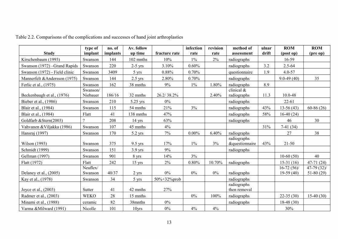
Table 22 Comparisons of the complications and successes of hand joint arthroplasties
Study type ofimplant
no ofimplants
Av follow up time fracture rate
infection rate
revision rate
method of assessment
ulnardrift
ROM(post op)
ROM(pre op)
Kirschenbaum (1993) Swanson 144 102 mnths 10 1 2 radiographs 16-59 Swanson (1972) ndashGrand Rapids Swanson 220 2-5 yrs 310 060 radiographs 32 25-64 Swanson (1972) - Field clinic Swanson 3409 5 yrs 088 070 questionnaire 19 40-57 Mannerfelt ampAndersson (1975) Swanson 144 25 yrs 280 070 radiographs 90-49 (40) 35Ferlic et al (1975) Swanson 162 38 mnths 9 1 180 radiographs 89
Beckenbaugh et al (1976) Swanson Niebauer 18616 32 mnths 262 382 240
clinical amp radiographs 113 100-48
Bieber et al (1986) Swanson 210 525 yrs 0 radiographs 22-61 Blair et al (1984) Swanson 115 54 mnths 21 3 radiographs 43 13-56 (43) 60-86 (26)Blair et al (1984) Flatt 41 138 mnths 47 radiographs 58 16-40 (24) Goldfarb ampStern(2003) 208 14 yrs 63 radiographs 46 30Vahvanen ampViljakka (1986) Swanson 107 45 mnths 4 31 7-41 (34) Hansraj (1997) Swanson 170 52 yrs 7 000 640 radiographs 27 38
Wilson (1993) Swanson 375 95 yrs 17 1 3radiographs ampquestionnaire 43 21-50
Schmidt (1999) Swanson 151 39 yrs 9 radiographs Gellman (1997) Swanson 901 8 yrs 14 3 10-60 (50) 40Flatt (1972) Flatt 242 15 yrs 2 080 1070 radiographs 15-31 (16) 47-71 (24)
Delaney et al (2005)Neuflex Swanson 4037 2 yrs 0 0 0 radiographs
16-72 (56) 19-59 (40)
47-79 (32) 51-80 (29)
Kay et al (1978) Swanson 34 5 yrs 50+32prob radiographs
Joyce et al (2003) Sutter 41 42 mnths 27 radiographs then removal
Radmer et al (2003) WEKO 28 15 mnths 0 100 radiographs 22-35 (30) 15-40 (30)Minami et al (1988) ceramic 82 38mnths 0 radiographs 18-48 (30) Varma ampMilward (1991) Nicolle 101 10yrs 0 4 4 30
13
Fig 28 Swanson implant (Swanson 1972)
Another silicone implant the Neibauer first used in 1966 was reinforced both
internally and externally with Dacron for strength and fixation respectively However these
two materials differ in mechanical properties and so results in stress at the interface between
the two and so the softer material inevitably deforms Both Hagert (1975) and Beckenbaugh
(1976) report relatively high fracture rates 537 and 382 respectively suggesting the
prosthesis is not strong enough to withstand the forces it is subjected to
The Sutter metacarpal prosthesis was designed to be an improvement on the Swanson
implant Designed in 1987 it comes in seven different sizes to fit different fingers The Sutter
is made from a material called ldquoSilflexrdquo claimed to give greater range of movement than the
Swanson The centre of flexion is palmar to the implantrsquos longitudinal axis suggested to
make extension easier Joyce et al (2003) reviewed 41 implanted Sutter prostheses twelve
were removed after an average of 42 months post surgery Of these removed eleven had
fractured ten completely (shown in Fig 29) These ten fractures all occurred at the junction
between the distal stem and the hinge region the same area that Swanson implants are known
to fracture
Fig 29 Fractured Sutter prostheses (Joyce et al 2003)
14
Joyce et al (2003) also conducted simulator tests on two Sutter prostheses One
completed just over 10 million cycles of flexion-extension the other 53 million Both
fractured in the same place as those removed from patients this is also the same region found
to be the location of fracture in the Swanson implants Of the retrieved implants many had a
rectangular shaped fracture face suggesting that the silicone had torn along the small radii at
the junction between the stems and central hinge This lead to the proposal that as the
prosthesis is made of silicone it will be bending not only at the hinge but at the stem as well
and as these have a small cross sectional area and can not withstand the forces the majority of
fractures occur here
Other flexible implants include the Helal with a dorsal-ulnar flap attempted to
overcome ulnar drift and the Calnan-Reis prosthesis a single polyethylene component fixed
by cement (Calnan ampReis 1968) Neither showed outstanding results with the Swanson
implant still deemed superior
224 Third generation
Third generation implants developed more recently are so called ldquototalrdquo implants
compromising several components These include the Kessler (1974) Hagert (1986)
Beckenbaugh (1983) and Ludborg (1993) implants shown in Fig 210 (Beevers ampSeedhom
1995) all made from different materials
Fig 210 Third generation implants (Beevers ampSeedhom 1995)
With all these implants longer follow up studies are needed to give a better
understanding of the success and possible complications that may occur These implants are
not suitable for severe RA patients with bone erosions and considerable deformity as
ligaments and muscles are needed for stability of the implant The Swanson implant remains
the most commonly used and preferred due to the ease of implanting and also removal if
necessary and also the low cost of the prosthesis (Beevers ampSeedhom 1995)
15
The Neuflex is the newest prosthesis on the market developed in 1998 by DePuy Its
major design feature is the 30 degree neutral angle intended to replicate the hands natural
resting position therefore supposedly reducing stresses on the implant and in particular the
central hinge region Furthermore manufacturers state that it will optimise comfort and
require less force to flex the fingers It is a single piece silicone prosthesis of Anasil silicone
and seven possible sizes have been made to suit all individuals Delaney et al (2005)
compare 10 Swanson and 12 Neuflex implants in a random allocation study after 2 years post
surgery Although there were no observed fractures silicone synovotis or infection reported
they found that the Neuflex had a 13 degree greater flexion range than the Swanson
However they discovered no differences between function grip strength or ulnar deviation
recurrence Joyce and Unsworth (2005) tested the Neuflex in vitro using a single station
simulator Testing 3 size 30 implants they found them capable of 94 103 and 199 million
flexion-extension cycles before fracture occurred All three fractured along the pivot of the
central hinge region This compares to the Sutter that fractured at just over 10 million and 53
million cycles (Joyce et al 2003) and the Swanson that reportedly survived 400 million
cycles with no problems (Swanson 1972)
225 Complications
As highlighted above success of the implants has been mixed and some reported
revision rates are quite high Data varies greatly and fracture rates have been reported
anywhere from 0 up to 82 A summary of the different findings is shown in table 22
Goldfarb and Stern (2003) evaluated 208 arthroplasties an average of fourteen years
postoperatively Of these 63 were broken with an additional 22 deformed at the time of
final follow-up Kay et al (1978) report the highest fracture rate of 82 in Swanson
prostheses followed for 5years Out of 34 joint replacements 17 were definitely fractured
with 11 probable cases The most frequent facture location was the base of the distal stem
Patients may not be aware when their prosthesis has fractured as it often does not
cause pain and range of motion may not be greatly affected either (Beckenbaugh 1976 Kay
1978 Kirschenbaum 1993) Therefore this could be one reason why reported fracture rates
differ and true rates may in fact be even larger A further reason for the variation in reported
rates may be the methods of assessment clinical assessment is unlikely to detect fracture and
even radiographs are difficult to interpret fractures and may miss some The only definitive
way to determine implant fracture is to remove and then carefully study it
16
It is clear in many cases that the implant may have broken but if it is not causing any pain and
is still providing functionality then it would not be appropriate to remove as would subject the
patient to further unnecessary surgery and pain Out of twelve removed Sutter prostheses
eleven were fractured after 42 months (Joyce et al 2003) However after fracture the
implant may be unable to support repetitive loading patterns that are experienced during every
day activities (Fowler ampNicol 2002)
Joyce et al (2003) suggest an alternative explanation for fracture based on the nature
of loading in MCP joints of rheumatoid patients where subluxing forces often dominate This
can lead to the cortical bone of the proximal phalanx to rub on the distal stem of the
prosthesis Any small abrasion may result in production of a stress concentration followed
quickly by fatigue failure at the junction between the distal stem and hinge of the implant
This theory is supported by their findings on the Sutter implant and also the Swanson
A further problem that can occur with silicone implants is silicone synovitis (shown in
Fig 211) This is caused by repeated rubbing of the implant against bony or sharp surfaces
leading to silicone wear particles inducing an immune response causing release of
multinucleated giant cells and synovial hypertrophy (Lanzetta et al 1994) Characteristic
radiological changes including the development of cysts in adjacent bones may occur without
symptoms whereas others will encounter pain joint stiffness loss of motion and swelling of
soft tissue (Khoo et al 2004) To reduce this problem titanium (Ti) grommets were
introduced to prevent abrasion of the silicone These are additional titanium sleeves which are
fixed to the implants to reduce wear of the silicone from sharp bone surfaces Grommets have
been shown to decrease fracture and osteolysis (Schmidt 1999) with grommets 0 of
prostheses fractured compared to without the grommets where a fracture rate of 15 was
observed However Ti grommets may also result in further problems as then the titanium is
worn and debris also causes inflammatory responses (Khoo et al 2004)
17
Fig 211 Silicone synovitis (from Trail 2006)
A further reported complication of implants is infection which is much rarer with
some reported rates shown in table 22 Further problems include skin necrosis immediately
post surgery due to the thin nature of arthritic skin and treatment of steroids which can
contribute to poor healing Dislocation of stems has also been noted with swelling of the
palm observed Another issue to consider is recurrent ulnar drift Trail (2006) suggests this is
in fact inevitable rates of ulnar drift are also shown in table 22
It is currently unknown why fracture occurs so frequently It has been suggested that
turning and rotation at the wrist joint can cause wrist implants to become damaged after
repeated twisting which they are not designed for (Palmer et al 1985) It may be that the
same applies at the finger joints which are assumed to only use two planes of movement but
may in fact need to allow for rotation also The movement analysis needs to be reviewed in
order to determine what range of movement occurs at these joints and furthermore what range
of movement is needed for arthritic patients It is not realistic to attempt to give them a range
equivalent to non diseased hands and neither is it necessary As has been suggested in wrist
implants designs should focus on a more limited applicable range of motion rather than
attempting to restore a complete normal range (Shepherd 2002) What needs to be determined
is what functional range of movement is needed to improve the quality of life Therefore in
order to design a better implant with a lower fracture rate the movement at the finger joints
needs to be examined in greater detail
18
23 Material properties of silicone
231 Introduction
The materials from which finger implants are made could provide further clues as to
why these devices are fracturing with relative frequency Silicones will be discussed in this
chapter as they remain the most common material used as mentioned in the previous chapter
232 Structure
Silicones are all composed primarily of molecules containing a backbone of alternate
silicon and oxygen atoms with some organic side groups most commonly the methyl group
when it is known as poly(dimethyl siloxane) (PDMS) the structure for which can be seen in
Fig 212 However different organic side groups are also found (Lambert 2006) Silicone
polymers can be transformed into elastomers by cross linking reactions forming chemical
bonds between adjacent chains (Colas amp Curtis 2005)
Fig 212 Basic structure of PDMS (Lambert 2006)
233 Properties
There are many properties of silicones that make them an excellent choice for use as
an implant Not least of all their biocompatibility with low toxicity and non reactive nature
the silicone implants are generally well tolerated by the human body and will not cause any
harm or unwanted response It is siliconersquos semi-inorganic structure that allows it to be placed
in the body without being absorbed and also means the mechanical properties will not be
affected (Yoda 1998) again of great importance for use as an implant
19
The flexible elastic properties of silicones allow movement of the arthroplasty Due to
the low glass transition temperature (Tg) as a result of low intermolecular interactions (Colas
ampCurtis 2005) silicone implants will be rubbery at body temperature and not will not
experience any temperature that will degrade them or effect their physical properties
234 Failure
Initiation of fractures in silicone prostheses can be caused by several possibilities the
first being accidental scratching during implantation of the arthroplasty as a result of the
surgical technique (Hutchinson et al 1997) any nick can then act as an initiation site for
cracks After studying the surgical technique Weightman et al (1972) suggested that poor
surgical technique could create a step off point and therefore increase the stress in the bending
element of the device enough to cause fracture Sharp edges of the bone may also rub against
the silicone implant especially during flexion due to subluxing forces of the rheumatoid hand
(Joyce et al 2003) again causing a crack initiation site It has also been suggested that the
cross links may not be uniform throughout the silicone and these local inhomogenities can
then act as microvoid initiation sites (Kinloch ampYoung 1988) Once created by any of these
possibilities these crack initiation sites will then grow under certain conditions primarily
repeated dynamic loading (Kinloch ampYoung 1988) such as with use in the finger joint Once
an initiation site has been introduced it has been shown that even under low strains of 10
crack growth rate can be 25x10-5 mmcycle in medical grade silicones when tested using pure
shear tests During flexion strain is believed to be much greater meaning crack growth will be
even quicker (Leslie et al 2008)
Failure may also occur as a result of the environment into which the implant is placed
so that over time its mechanical and physical properties are altered and it will not function as
initially intended Many experiments have been carried out to investigate different
environmental conditions Swanson and Lebeau (1974) implanted silicone rubber specimens
in beagles then removed and studied the physical properties After 2 years the tensile strength
decreased by 8 elongation by 15 and the elastic modulus increased by 16 showing how
the implants performance could be reduced over time and how it could be more susceptible to
fracture Leslie et al (2007) found placing samples of medical grade silicones in mild
environmental conditions at body temperature caused true stress at failure to be reduced over
time showing reduced strength With an elevated temperature this effect was even greater
suggesting the mechanism that reduces strength could be thermally activated
20
It is however still unclear exactly how the material changes Evidence from fourier transform
infra-red (FTIR) spectroscopy and gel permeation chromatography (GPC) did not support the
proposed theory that continued cross-linking affects properties However Leslie et al (2008)
did find other support for the assumption suggesting that the changing absorbencies found
with FTIR analysis may be indicating competing processes are taking place possibly
continued cross-linking is occurring but alongside oxidation Support for this comes from
findings of more pronounced changes in properties of the samples aged in air compared to
distilled water and Ringerrsquos solution However it has also been shown that cyclic testing in
vitro at 37 degrees did not cause finger implants to fracture after 10 million cycles
(Weightman et al 1972) Although discoloration of the prostheses was seen at the point of
bending suggesting continued stress concentration could lead to fracture eventually
A further problem and possible source of failure comes from silicones lipophilic
nature so they can be swollen by lipids absorbed from the body Swanson and Lebeau (1974)
reported maximum weight gain over the two years after silicone implantation was 091 and
was due mainly to lipid absorption However lipid and fatty acid absorption was found to be
much lower in finger implants and furthermore was not related to duration of implantation
failure or cracks observed after removal (Meester ampSwanson 1972) Lipid absorption was
also noted by Weightman et al (1972) with significant amounts of triglycerides and
cholesterol found on fractured prosthesis but they suggest that if inserted properly the implant
should be successful despite this
To conclude it appears that the properties of silicones have an important role in the
success of finger implants The main problem seems to be the fast rate of crack propagation
once a small initiation site has been created Reducing the chance of such a crack from being
introduced seems to be of key importance this can be achieved by careful surgery both when
using sharp implements but also in ensuring no jagged bone edges are left The continued
rubbing of bone on the implant may be unavoidable due to the subluxing nature of the
rheumatoid hand in which case the implant material needs to be improved to withstand such
impingements It is important to consider the materials properties and behaviours in
conjunction with the information about the forces and movements that prostheses are
subjected to once implanted
21
24 Methods to assess hand movement
241 Introduction
A better understanding and more detailed information of hand movement is needed to
provide some clues as to why finger implant fracture rates are so high and possibly even how
they could be reduced This includes more accurate angle measurements and in depth data on
movement patterns There are a variety of different methods available to measure the
movement at joints ranging from the very basic such as visual estimation and composite
finger flexion which are less reliable (Ellis ampBruton 2000) to much more complex options
such as goniometry and motion analysis
242 Goniometery
The goniometer is an extremely useful tool to measure range of movement (shown in
Fig 213) It is quick and easy lending itself well to use in large clinical studies Reliability of
the goniometer is relatively high (Ellis ampBruton 2000) making it more effective than basic
measurements However the reliability is dependent on the tester factors such as experience
and technique can affect angles recorded If measured by different testers joint angles at the
hand can vary by plusmn7ndash9 degrees compared to plusmn4ndash5 degrees if the same person is taking
measurements (Ellis ampBruton 2000) However goniometers do not provide very accurate
data and give limited information about how different joints move to perform everyday tasks
or activities These and other more comprehensive details would be necessary to understand
the specifics for implant design Goniometry also only tests one joint of one finger at a time
in a fixed position therefore not giving active ROM and in order to calculate an average
value for each joint of the hand considerable time would be required Another disadvantage is
the examiners could influence angles achieved by forcing movements that would not be
performed in everyday tasks so would not accurately represent the true nature of natural
movement The main limitation of using a goniometer to investigate hand movement in
diseased hands is that they are only able to measure in 2-D and therefore errors would arise
from the disfigured joints and data would not be representing the movement accurately
22
Fig 213 several different goniometers (Stam et al 2006)
243 Gloves
The use of gloves has also been put forward as a measuring tool for hand movement
One example the CyberGloveTM (Virtual Technologies Inc 1992) has a mean error less
than 6 degrees for all flexion and abduction angles (Kessler et al 1995) However error
ranged from 03 degrees at the middle finger to 55 degrees at the index finger MCP joint
(Yun et al 2002) The SIGMA (Sheffield Instrumented Glove for Manual Assessment) glove
shown in Fig 214 has also been developed (Williams et al 2000) Error for finger flexion
was found to fall between plusmn5 degrees again comparable to goniometry Along with problems
in accuracy at different joints the glove has several other disadvantages mainly that the sizes
of gloves will not fit every hand in the same way and therefore one can not guarantee that the
fibres of the gloves are accurately placed over the anatomical landmarks required This would
be even more apparent in diseased or injured patients where the glove is very unlikely to fit
inflamed or deformed hands and could cause considerable pain if forced As no single
deformity is the same it is unlikely this problem could be overcome or standardised In
addition the glove may in fact restrict normal movement
Fig 214 SIGMA glove and interface box (Williams et al 2000)
23
244 Three dimensional motion analysis
Three dimensional motion analysis is a further more complex method available for
measuring hand movement The system utilises high resolution cameras with LED strobe
lights around the lens Subjects wear retro-reflective markers placed in pre-defined landmarks
and as they move in the capture volume light is reflected back into the camera lens strikes a
light sensitive plate within and so creates a video signal Motion analysis can therefore
capture the active ranges of motion (AROM) of hand joints so recording changes in angles at
all three finger joints continuously during movement of the finger Rash et al (1999) showed
markers placed on the dorsal aspect of the hand and fingers can be used to accurately measure
joint angles using motion analysis Therefore motion analysis presents a major advantage in
its ability to provide more information than conventional goniometer measurements as it
demonstrates the dynamic changes in the finger joints during motion This method also
produces much more information about movement at the individual joint it allows angles to
be measured in more than one plane so can investigate flexion extension adduction
abduction and rotation all at the same time Chiu et al (1998) have shown it is possible to
measure the angles of finger joints during motion analysis evaluation by adding more
reflective markers and the data derived are comparable to the measurements obtained with a
conventional goniometer
However 3-D motion capture still has disadvantages it can be considerably time
consuming because accurate placing of markers one-by-one is slow The main disadvantage
is that during movement muscle deformations and skin sliding will inevitably occur
particularly with older skin The severity of this problem depends on where the markers are
placed and will be discussed with the relevant marker sets
Despite some disadvantages motion analysis still remains the most accurate method to
assess joint movement in the hand although time consuming the benefits in terms of accuracy
and information captured far outweigh this
245 Marker sets
Current marker systems used for motion analysis often place only a single marker on
each phalanx which does not accurately define a segment Three markers per segment are
required to provide data on rotation at a joint There is however no standardised set of marker
positions although suggestions have been made by the International Society of Biomechanics
(Wu et al 2005) There are several different approaches that have been taken by different
research teams
24
Simple marker systems have been proposed by Cerveri et al (2007) shown in Fig
215 and also Carpinella et al (2006) Markers are placed directly over the joint centres and
on the finger tips on the distal border of the nail This marker set may provide much quicker
testing durations as less markers have to be attached therefore would be very useful for
clinical research on a large scale Using fewer markers could also be of benefit when testing
hand motion in children where there is not a large enough surface area to place more markers
However having so few markers prevents complex or accurate information from being
obtained The main disadvantage with this system is placing the markers directly over the
joints where skin movement will be greatest This causes markers to move non-rigidly with
respect to the underlying bones the markers will then no longer correspond to their pre-
determined locations Therefore this marker set will produce angle data that does not
accurately represent the movement of the joints Consequently other marker sets have been
proposed to improve the accuracy of measurements and limit the effect of skin movement by
placing markers in alternative positions
Fig 215 Ceveri et al (2007) simple marker set
Chiu et al (1998) and Su et al (2005) both place two markers on each phalanx
shown in Fig 216 except at the distal phalanx were a single marker is used This means when
calculating the angle measurements at the PIP and DIP joints accuracy will be compromised
Su et al (2005) report an accuracy of up to 01 in position and 02 degrees in angle
measurement The only issue with these more complex marker systems is the increased
assessment time both the accurate placing and the analysis of more markers creates a more
time consuming process
25
Fig 216 marker set Chiu et al (1998)
Floating marker clusters have also been used (Fowler ampNicol 1999 2001 2002 and
Degeorges et al 2005) They consist of three carbon fibre pins protruding from a base
forming a triad arrangement with markers attached to the ends as shown in Fig 217 This
method allows more markers to be used to gain information about the joint without concern
about fitting enough markers on each segment However if floating clusters were used for
every finger there would be too many markers for such a small capture volume Markers
could knock each other during movement and occlude others from the cameras Furthermore
these types of markers may not be appropriate when testing RA patients as severe swelling
and deformities could cause one cluster to protrude onto another if placed on every finger and
large clusters may not be suitable for children with smaller hands either However unlike the
other marker systems floating clusters can give information about rotation at the joints
Fig 217 Floating markers Fowler amp Nicol (2001)
26
To conclude although the more complex marker sets (Chiu et al 1998 Su et al
2005) with two markers on each phalanx give more accurate data on flexionextension and
abductionadduction they are still lacking two markers on the distal phalanx Certainly adding
extra markers to the finger tips needs to be tested to see if it is achievable in such a small
volume The current marker sets with exception of the floating clusters are also unable to
provide rotational data For rotation to be measured more markers need to be added to the
fingers which may not be possible as the error of the movement may be too great for the
small degree of rotation actually occurring at the joints but this possibility needs to be tested
also
The use of motion analysis on rheumatoid hands is also limited with the only study to
my knowledge conducted by Fowler and Nicol (2001) using their floating markers on eight
RA patients and eight controls and then repeated with eight post MCP replacement patients
(2002) However as discussed this marker set may cause problems when assessing the whole
hand and using another marker set may give more accurate results
27
3 EXPERIMENTAL METHODS
31 Ethical considerations
As the study involved using healthy volunteers and NHS patients strict ethical
guidelines had to be followed Ethical approval was granted by the University of Worcester
for use of the staff and students as participants The NHS ethical application process involved
a 34 page document completed on line (Appendix 1) and then sent to the Warwickshire
Research Ethical Committee to review After attending a committee hearing and making
small changes to the patient information and consent forms the study was granted favourable
ethical approval (Appendix 2) Approval was then also given by the local R and D
department
32 Subjects
Four experimental groups were used each consisting of ten subjects Two control
groups of young adults (age 23 plusmn 36years) and older adults (age 56 plusmn 74years) were recruited
from the University environment Both control groups went through screening to ensure they
showed no symptoms of hand disease or previous injurysurgery that would affect joint
movement The screening questionnaire (Appendix 3) was completed by participants after
reading the participant information sheet (Appendix 4) and giving informed consent
(Appendix 5) before being tested
Two patient groups were used both suffering from rheumatoid arthritis One group
(age 60plusmn 92years) consisted of stable rheumatoid arthritis patients with no history of surgery
and the other group (age 67plusmn 128years) had Swanson Metacarpophalangeal (MCP)
arthroplasty in all four MCP joints at least two years previously Patients were excluded if
they had any other surgery on the hand or if the implant showed signs of fracture determined
by radiographs Patients were also excluded if they had a current acute flare up All patients
were currently attending routine out-patients clinics Suitable subjects received an invitation
letter (Appendix 6) to ask them to participate Any patients who indicated their interest were
contacted via telephone and sent further information (Appendix 7) Those who agreed to
participate in the study were then asked to give informed consent (Appendix 8) and a letter
sent to inform their GP (Appendix 9) Patients were not given questionnaires or asked any
specific questions during testing but often they were keen to discuss their disease or their
finger replacements
28
All subjects were right hand dominant and only right hands were studied All
participants used were female Subject characteristics are shown in tables 31a and b All
testing took place at the Motion Analysis Research and Rehabilitation Centre (MARRC)
University of Worcester
Clinical data collected included a recently taken Disease Assessment Questionnaire
(DAS) (Appendix 10) and blood tests from a maximum of two weeks prior to testing to
ensure validity X-rays of patientrsquos hands were also available for review
Table 31a Subject characteristics of control subjects
Table 31b Subject characteristics of patient subjects
Subject Age DOB Subject Age DOBYN01 21 23051986 EN01 61 04021947YN02 30 07041977 EN02 51 20011957YN03 27 28101981 EN03 53 05031955YN04 21 28091986 EN04 63 23111945YN05 21 15091986 EN05 41 23021967YN07 21 23021987 EN06 64 28081944YN08 22 27111985 EN07 62 11071946YN09 22 EN08 58 19091950YN10 25 12021983 EN09 61 20091947YN11 29 21101979 EN10 50 26091958
Average 239 564SD 357 743
Subje Subject Age DOBDAS score Subject Age DOB
DAS score
Yrs post OP
RA01 49 26101959 411 MCP1 48 01051960 372 490RA02 61 01081947 255 MCP2 76 26011932 477 450RA03 65 21011943 432 MCP3 74 11111933 209 260RA04 71 31051937 384 MCP5 71 31011937 209 430RA05 61 05091947 41 MCP6 78 07121929 421 360RA06 40 14011968 379 MCP7 88 06011920 304 380RA07 68 07021940 3 MCP8 58 26101950 278 480RA08 61 05021947 347 MCP9 71 01021937 403 540RA09 63 28061945 353 MCP10 59 23021949 164 350RA10 64 25091944 418 MCP12 51 17111957 169 190
Average 603 381 674 301 393SD 917 045 1284 113 103
29
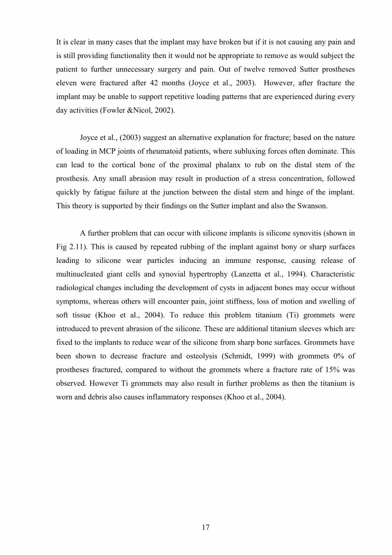
33 Motion analysis
A Vicon M2 (624) (Vicon Peak Oxford UK) motion capture system was used to
capture hand kinematic data Twelve Vicon cameras and one video camera were positioned in
an arc around the working volume at varying heights exact camera set up is shown in Figs
31 and 33 This camera set up was developed during pilot testing using trial and error over
several months Many of the various factors involved were constantly changed and many
different combinations trialled These included the distance from the cameras to the hand the
height position and number of cameras and also the degree of the arc that the cameras made
around the hand Once a capture of good enough quality was achieved the exact set up was
recorded Cameras have a ring of LED strobe lights fixed around the lens so that they can be
adjusted The chair was placed in the centre of the arc with the right front leg placed over a
marker on the floor to standardise placement This marker is also used as the central point to
position the cameras using the distances in table 32
Fig 31 Camera set up
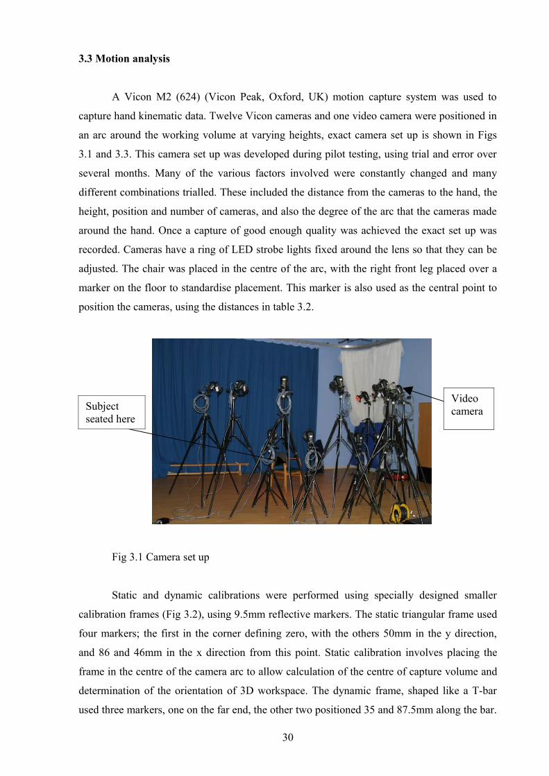
Static and dynamic calibrations were performed using specially designed smaller
calibration frames (Fig 32) using 95mm reflective markers The static triangular frame used
four markers the first in the corner defining zero with the others 50mm in the y direction
and 86 and 46mm in the x direction from this point Static calibration involves placing the
frame in the centre of the camera arc to allow calculation of the centre of capture volume and
determination of the orientation of 3D workspace The dynamic frame shaped like a T-bar
used three markers one on the far end the other two positioned 35 and 875mm along the bar
30
Video cameraSubject
seated here
Dynamic calibration is performed by waving the wand within the capture volume to allow the
system to calculate the positions and orientations relative to one another Calibration residuals
of 06mm or less were achieved each time with sampling carried out at 60 Hz
Fig 32 Small static and dynamic calibration frames
Fig 33 Overhead view of camera positions
Strobe intensity ie the level of light from the LEDs for all cameras was set between
4-5 for each session The sensitivity recorded in table 32 was used as a starting point with
small adjustments made as necessary Each session the cameras were all carefully focused on
a mock hand consisting of 24 markers attached to wooden splints to ensure that data collected
would be successful
31
lsquoCentrersquo point for hand position
Table 32 Camera set up
Position Cam number Distance from
centre (m)
Sensitivity Gain
1 12 18 65 52 13 19 55 5
3 (L) 7 165 65 54 8 21 75 5
5(L) 14 175 70 56 10 21 65 5
7(L) 9 175 63 58 5 21 80 5
9(L) 15 175 65 510 16 215 68 511 4 2 68 512 1 18 70 5
Corner away from garage
(L) lower cameras
34 retro-reflective hemispherical markers (Vicon Oxford UK) were placed on the
dorsal aspect of the hand Four markers on the wrist (85mm in diameter) six markers to
define the hand (5mm diameter) and twenty four markers on the fingers (3mm diameter)
Several marker sets were tested during pilot testing (Appendix 11) with varying numbers and
positions of markers Three volunteers were used for pilot testing trying many different
combinations of marker positions as well as different numbers and sizes of markers The
position of the hand within the capture volume was also altered several times to find the best
angle to capture all markers as much as possible throughout the movements The marker set
used is shown in Fig 34 with the anatomical positions described in Appendix 12 For error
analysis of the three main marker sets one female volunteer was used The distance between
pairs of markers at the proximal middle and distal phalanxes of the index finger during
movement was recorded Results (Appendix 11) showed this marker set gave the lowest
standard deviations of distance between the markers over nine repeats of a pinch grip
Therefore it showed the lowest level of skin movement artefact and greatest accuracy
compared to the other models tested
32
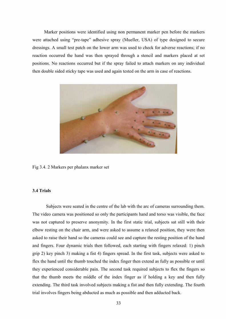
Marker positions were identified using non permanent marker pen before the markers
were attached using ldquopre-taperdquo adhesive spray (Mueller USA) of type designed to secure
dressings A small test patch on the lower arm was used to check for adverse reactions if no
reaction occurred the hand was then sprayed through a stencil and markers placed at set
positions No reactions occurred but if the spray failed to attach markers on any individual
then double sided sticky tape was used and again tested on the arm in case of reactions
Fig 34 2 Markers per phalanx marker set
34 Trials
Subjects were seated in the centre of the lab with the arc of cameras surrounding them
The video camera was positioned so only the participants hand and torso was visible the face
was not captured to preserve anonymity In the first static trial subjects sat still with their
elbow resting on the chair arm and were asked to assume a relaxed position they were then
asked to raise their hand so the cameras could see and capture the resting position of the hand
and fingers Four dynamic trials then followed each starting with fingers relaxed 1) pinch
grip 2) key pinch 3) making a fist 4) fingers spread In the first task subjects were asked to
flex the hand until the thumb touched the index finger then extend as fully as possible or until
they experienced considerable pain The second task required subjects to flex the fingers so
that the thumb meets the middle of the index finger as if holding a key and then fully
extending The third task involved subjects making a fist and then fully extending The fourth
trial involves fingers being abducted as much as possible and then adducted back
33
Each action was completed 3 times per set with 3 sets completed and a short rest time
was allowed in between each set Each participant completed trials in the same set order
completing tasks 1 2 3 and then 4 Subjects were asked to complete as much of the
movement as possible but not to do anything that caused considerable pain
35 Analysis
The data collected from the camera were then reconstructed using pre-determined
parameters (Max acceleration 5 Max noise factor 1 Intersection limit 2 residual factor
05 Predictor radius 3) to produce a trajectory for each marker These trajectories were then
labelled according to the corresponding landmarks Labelling of each trial was performed by
first manually creating an auto label of the static trial for each subject that would then be used
to speed up labelling of the dynamic trials To create an auto label each marker was selected
and manually labelled to correspond to the anatomical landmark that is represents this set of
labelled markers and relative positions would then be saved and can be applied to each trial of
that subject Any missed markers after the autolabel had been run were manually labelled
Trajectories were then defragmented and any gaps therefore occlusion of markers up to 6
frames long were auto-filled Trials were then further cleaned if any crossover appeared
where markers were getting swapped over to perform this the wrong data points needed to
be snipped before being defragmented and the new trajectory labelled correctly Some larger
gaps on the hand were filled using Vicon GenPatch (Appendix 13) and Replace4 (Appendix
14) models as appropriate As long as all other markers in the set are present it uses the
information on the distances among these to determine where the missing marker should be
Data was then modelled using the missing data model (Appendix15) to locate where the gaps
were and record this information to ensure these data points would not be used to determine
crucial peak angle results All gaps in the data were then filled to allow smoother filtering A
Butterworth filter with a cut-off frequency of 1Hz was then run before modelling using the 2
markers per phalanx marker model (Appendix 16) to calculate angles at the finger joints
Flexionextension and adductionabduction are calculated at all the MCP PIP and DIP joints
and selected angles exported to Vicon Polygon to create reports and view the results
(examples of which can be seen in Appendix 17) Angle data was also exported into excel to
manipulate data The three peaks and three troughs of each trial were selected and then results
collated for each subject and group
34
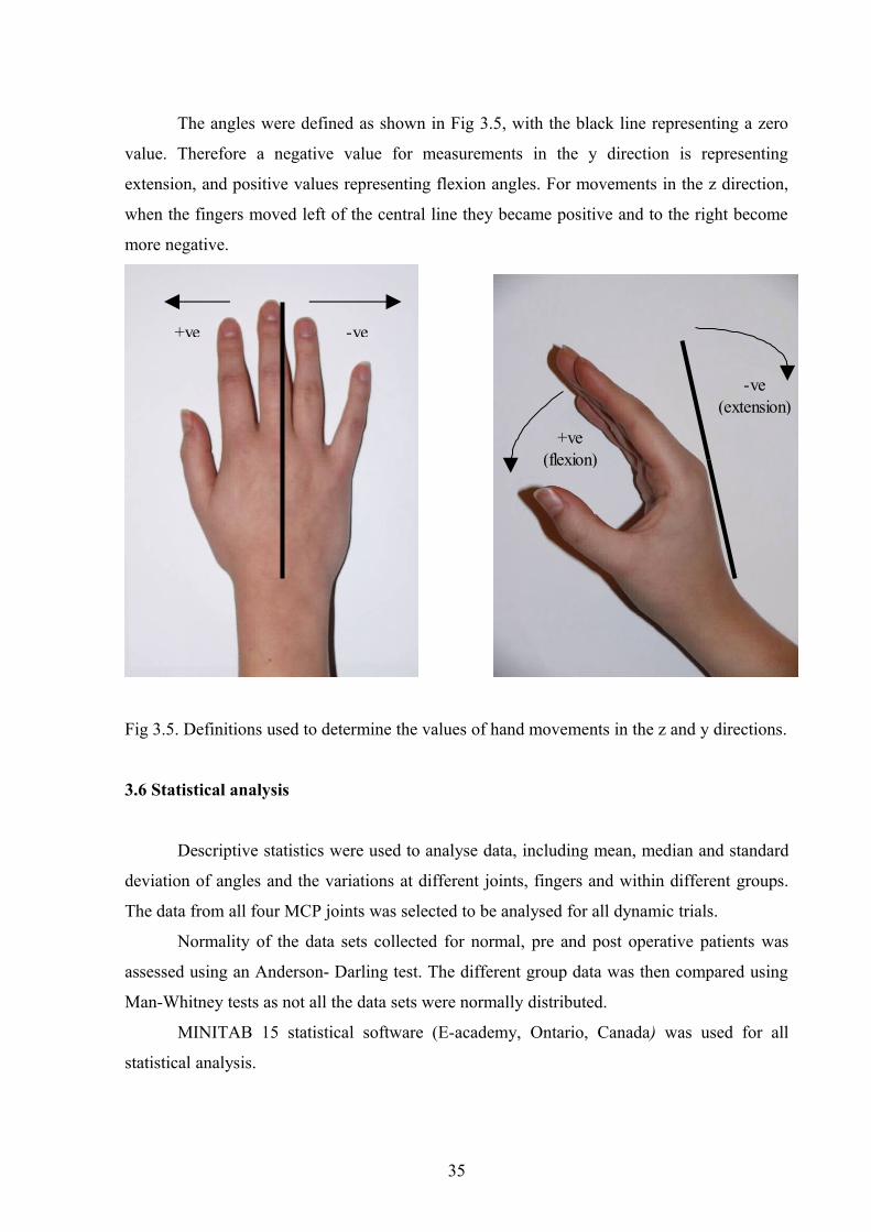
The angles were defined as shown in Fig 35 with the black line representing a zero
value Therefore a negative value for measurements in the y direction is representing
extension and positive values representing flexion angles For movements in the z direction
when the fingers moved left of the central line they became positive and to the right become
more negative
Fig 35 Definitions used to determine the values of hand movements in the z and y directions
36 Statistical analysis
Descriptive statistics were used to analyse data including mean median and standard
deviation of angles and the variations at different joints fingers and within different groups
The data from all four MCP joints was selected to be analysed for all dynamic trials
Normality of the data sets collected for normal pre and post operative patients was
assessed using an Anderson- Darling test The different group data was then compared using
Man-Whitney tests as not all the data sets were normally distributed
MINITAB 15 statistical software (E-academy Ontario Canada) was used for all
statistical analysis
35
-ve+ve
-ve (extension)
+ve(flexion)
4 RESULTS
41 Introduction
Data from all the subjects young normals (YNs) elderly normals (ENs) rheumatoid
patients (RAs) and MCP replacement patients (MCPs) can be found on the results CD
(Appendix 18) This includes the minimum and maximum values for y and z direction
movements at the index middle ring and little finger MCP joints for all four movements for
all 40 subjects used Data is presented on the average minimum and maximum values plus
ROMs for each group in the tables looking at each movement in turn with the graphs
illustrating the differences in average ROMs for each group
42 Pinch grip
Average flexionextension ROMs for pinch grip
0
20
40
60
80
100
120
index middle ring littleFinger
Ave
rage
RO
M (d
egre
es)
YNENRAMCP
Fig 41 Average ROMs for all subject groups when performing the pinch grip Error bars represent plusmn 1 standard deviation Results are statistically significant (p lt 005) from YNs() ENs() and RAs ()
36
At all fingers average ROMs were significantly lower for the MCP patients (p lt 005)
compared to all other subject groups Although in Fig 41 the elderly controls appear to show
more limited movement than the young controls this was not significant and again the
rheumatoid patients were not significantly worse compared to the ENs although results
suggest a difference Table 41 shows that during the pinch movement the MCP subjects on
average were not able to achieve any degree of extension at any of the fingers as none of the
minimum y values are negative
43 Key grip
Average flexionextension ROMs for key grip
0
20
40
60
80
100
120
140
index middle ring littleFinger
Ave
rage
RO
M (d
egre
es)
YNENRAMCP
Fig 42 Average ROMs for all subject groups when performing the key gripError bars represent plusmn 1 standard deviation Results are statistically significant (p lt 005) from YNs() ENs() and RAs ()
Again the MCP subjects showed significantly lower average ROMs (p lt 005)
compared to both normal groups for all fingers and smaller than RAs for index and middle
fingers Although results suggest other trends between groups none of these were found to be
significant
37
44 Fist
Average flexionextension ROMs for fist
0
20
40
60
80
100
120
140
index middle ring littleFinger
Ave
rage
RO
M (d
egre
es)
YNEN
RAMCP
Fig 43 Average ROMs for all subject groups when making a fistError bars represent plusmn 1 standard deviation Results are statistically significant (p lt 005) from YNs() ENs() and RAs ()
When making a fist EN subjectsrsquo average ROM was significantly reduced compared
to the younger controls RAs showed significantly lower average range of movements
compared to the younger and also elderly controls with a further significant decrease found
for the MCPs at the index and middle fingers (p lt 005)
The first three movements all show the same pattern occurring with the YNs capable
of producing the greatest ROM for the pinch key and grip movements with highest values
seen during the fist grip There then appears to be an ageing effect as the ENs produce lower
values for all movements at all fingers although only significant at the fist The rheumatoid
patientrsquos movement is restricted to an even greater extent with values lower than both normal
populations again only significant when forming a fist The MCP replacement patients show
the lowest ROM for all movements and at all fingers significant at most fingers during all
movements suggesting that the implants were unable to restore movement to that of
rheumatoid let alone elderly normals This pattern of decreasing movement repeats itself at
all fingers across these three movements
38
bull
45 Spread
Average ROMs for spreading the hand
-10
0
10
20
30
40
50
60
70
80
index y index z middle y middle z ring y ring z little y little z
Finger and direction
Ave
rage
RO
M (d
egre
es)
YNENRAMCP
Fig 44 Average ROMs for all subject groups when spreading out the handError bars represent plusmn 1 standard deviation Results are statistically significant (p lt 005) from YNs() ENs() and RAs ()
The ROMs for the spread movement do not repeat the pattern seen in the other
movements although in general the control subjects are still producing higher ROMs at all
fingers there are a few exceptions and the results are not as clear as in the other graphs When
spreading out the hand movement in the y direction (ie flexionextension) was significantly
lower for MCP patients compared to both control groups (p lt 005) and although results
suggest a reduction in ROM compared to the RAs this was not found to be significant
Interestingly the ENsrsquo movement in the y direction was the highest at all the fingers seen
clearly in Fig 44 and movement was significantly greater at the ring finger (p lt 005) This
suggests in order to carry out this spreading movement ENs are needing to extend the fingers
backwards and also flex fingers to a greater extent at the MCP joints (as seen in table 44) so
are unable to keep the fingers straight as asked In the z direction results were similar to the
other movements with the MCPs again showing significantly reduced ROMs at all fingers
(p lt 005) compared to all other subject groups The RAs also appear to show reduced
movement in this direction although it is significantly so only at the index finger
39
Table 41 Average max min and ROMs (degrees) and standard deviations of projected angles for pinch grip
Index max y (SD)
Index max z (SD)
Index min y (SD)
Index min z (SD) ROM y (SD) ROM z (SD)
YN 6299 1186 432 567 -1643 969 -1099 370 7942 1524 1531 511EN 5383 1221 155 715 -1268 797 -1231 529 6651 1565 1386 578RA 4332 976 -711 1516 -754 1871 -2196 1318 5011 1953 1484 572MCP 4565 1656 -598 898 2078 1230 -1344 925 2487 1401 747 267
Middle max y (SD)
Middle max z (SD)
Middle min y (SD)
Middle min z (SD) ROM y (SD) ROM z (SD)
YN 6229 1319 -136 411 -2026 944 -943 494 8254 1545 807 341EN 5400 1181 -325 493 -1428 1153 -1181 403 6828 1797 856 400RA 5027 1529 -1263 1407 -336 2249 -2376 1271 5329 2254 1113 584MCP 4760 2356 -264 733 2100 1805 -737 688 2660 1274 473 276
Ring max y (SD)
Ring max z (SD)
Ring min y (SD)
Ring min z (SD) ROM y (SD) ROM z (SD)
YN 6185 1323 -034 394 -1675 907 -1855 423 7860 1417 1821 546EN 5430 1485 -434 644 -1665 1097 -1793 552 7095 2148 1359 443RA 5011 1762 -1528 1189 -1073 1782 -3191 1276 6084 2468 1664 899MCP 4188 1569 -515 860 898 1552 -1237 1019 3290 1479 722 218
Little max y (SD)
Little max z (SD)
Little min y (SD)
Little min z (SD) ROM y (SD) ROM z (SD)
YN 6544 1408 852 777 -1087 1120 -4128 854 7631 1645 4980 1094EN 5453 1956 -023 1387 -994 1045 -3994 944 6447 2737 3971 1431RA 6107 1605 -914 1603 346 1887 -4870 562 5761 2855 3956 1622MCP 3698 2225 -247 986 1179 2231 -1232 973 2520 1188 985 364
40
Table 42 Average Maximum minimum and ROMs with standard deviations of projected angles for key movement
Indexmax y (SD)
Indexmax z (SD)
Indexmin y (SD)
Indexmin z (SD) ROM y (SD) ROM z (SD)
YN 5624 964 117 480 1813 1107 -1659 376 7436 1435 1776 637EN 5126 1100 -127 756 1084 790 -1746 539 6210 1354 1619 718RA 4202 1291 -1154 1822 -754 1839 -2686 1304 4955 2264 1532 1031
MCP 4771 1682 -649 932 1910 1171 -1587 894 2861 1333 937 397
Middlemax y (SD)
Middlemax z (SD)
Middlemin y (SD)
Middlemin z (SD)
ROM y (SD) ROM z (SD)
YN 6707 1097 -435 409 1959 968 -1199 385 8666 1374 763 303EN 6121 1193 -556 321 1208 1265 -1417 415 7329 1786 861 404RA 5741 1219 -1398 1218 -285 2305 -2419 1344 5998 2753 779 963
MCP 5061 2076 -380 689 2033 1835 -1136 636 3029 1210 755 379
Ringmax y (SD)
Ringmax z (SD)
Ringmin y (SD)
Ringmin z (SD)
ROM y (SD) ROM z (SD)
YN 6637 1525 -170 435 1821 855 -1840 526 8457 1890 1670 578EN 6091 1232 -487 295 1334 1282 -1987 596 7425 1845 1500 596RA 5776 1914 -1443 1304 -891 1937 -3440 1317 6667 3172 1997 935
MCP 4402 1045 -535 871 829 1481 -1455 945 3573 1721 920 457
Littlemax y (SD)
Littlemax z (SD)
Littlemin y (SD)
Littlemin z (SD)
ROM y (SD) ROM z (SD)
YN 6925 2058 609 824 1732 1214 -4093 900 8657 3012 4702 1184EN 6128 1313 -021 755 -639 948 -4046 1285 6767 1790 4026 1484RA 6837 1782 -720 1563 679 2001 -4917 623 6158 3355 4197 1916
MCP 3937 1758 -524 825 804 2116 -1541 823 3133 1418 1017 411
41
Table 43 Average Maximum minimum and ROMs with standard deviations of projected angles for fist movement
Index max y (SD)
Indexmax z (SD)
Indexmin y (SD)
Index min z (SD) ROM y (SD) ROM z (SD)
YN 8078 1410 209 482 -1859 1240 -1472 447 9937 1762 1680 657EN 7036 1375 216 622 -1090 658 1475 374 8126 1270 1691 623RA 4949 1081 -1000 1399 -502 2199 -2737 961 5452 2787 1737 614MCP 5417 1414 -631 960 1875 1109 -1406 913 3542 1131 775 331
Middle max y (SD)
Middle max z (SD)
Middle min y (SD)
Middlemin z (SD) ROM y (SD)
ROM z (SD)
YN 8674 1028 -062 328 -2036 977 -1040 259 10710 1250 978 376EN 7991 1247 -247 290 -1358 1101 -1411 319 9348 1177 1164 351RA 6669 958 -1343 1041 -365 2319 -2465 1224 6929 2549 1089 362MCP 5953 1834 -311 742 2018 1772 -1055 715 3935 1117 744 333
Ring max y (SD)
Ring max z (SD)
Ring min y (SD)
Ring min z (SD) ROM y (SD)
ROM z (SD)
YN 8974 1037 356 326 -1895 812 -1855 402 10868 1119 2210 505EN 8120 1481 -051 262 -1508 1174 -1932 505 9629 1298 1882 629RA 7269 1404 -1068 983 -884 1651 -3505 1367 8033 2472 2579 1067MCP 5545 1451 -341 741 743 1540 -1399 917 4802 2099 1058 562
Little max y (SD)
Little max z (SD)
Little min y (SD)
Littlemin z (SD) ROM y (SD)
ROM z (SD)
YN 9135 1398 1557 677 -1822 1172 -3973 927 10957 2268 5531 1112EN 8113 1038 1204 566 -749 1066 -4234 1170 8788 1137 5438 1239RA 8004 918 243 1198 711 1699 -5012 491 7293 2209 5255 1358MCP 5168 1917 -188 738 898 2082 -1633 823 4361 2000 1446 625
42
Table 44 Average maximum minimum and ROMs with standard deviations for projected angles during spread movement
Index max y (SD)
Index max z (SD)
Indexmin y (SD)
Index min z (SD) ROM y (SD) ROM z(SD)
YN 2354 1141 1336 307 322 875 -1356 444 2032 1031 2691 434EN 4226 1241 1203 495 961 1331 -1420 492 3265 1424 2623 429RA 3108 1609 -053 1558 1464 1727 -1900 1404 1645 2050 1657 701MCP 3483 1410 -166 1290 2497 1242 -1215 1060 985 565 1049 590
Middle max y (SD)
Middle max z (SD)
Middlemin y (SD)
Middle min z (SD)
ROM y (SD) ROM z (SD)
YN 2478 1219 -030 430 -481 506 -694 426 2960 1236 664 152EN 4338 1459 -157 463 -263 1465 -908 209 4601 2004 751 298RA 3904 1202 -558 1298 749 1732 -1422 1342 3155 1577 864 364MCP 3510 1875 -215 778 2347 1834 -668 766 1163 600 454 273
Ring max y (SD)
Ring max z (SD)
Ring min y (SD)
Ring min z (SD)
ROM y (SD) ROM z (SD)
YN 2166 1155 102 418 -510 540 -2235 564 2676 1157 2338 741EN 4329 1284 -237 402 -576 1315 -2462 464 4905 1936 2226 582RA 3422 1183 -761 1550 525 1729 -2743 1502 2897 1488 1982 878MCP 3203 1959 -320 995 1963 2304 -1157 1026 1240 607 837 481
Little max y (SD)
Little max z (SD)
Little min y (SD)
Little min z (SD)
ROM y (SD) ROM z (SD)
YN 1759 1082 329 353 -253 816 -4431 920 2012 847 4760 962EN 4096 1514 360 309 573 1612 -4958 832 3523 1832 5318 807RA 3964 1565 -364 1213 1780 1914 -4228 738 2184 1380 3864 1662MCP 3030 2178 -301 874 1378 2133 -1828 1139 1652 662 1526 1122
43
46 Patient feedback
Although no questionnaire was given to patients who took part in the study many were
keen to volunteer information and often wanted to talk about their disease or the surgery they
had had All the post surgery patients who talked about their procedure were extremely happy
with the results of their operation and keen to tell me how much better it had made their lives
The focus of the improvement differed with several commenting on the improved appearance
of the hand especially straightening of the fingers Others were more relieved about the lack
of pain they now experience and their ability to do many more everyday tasks since their
operation So from the information they chose to volunteer it is clear that they all felt the
procedure extremely worthwhile and effective indeed many had been so pleased with results
they had the other hand operated on as well When the rheumatoid patients talked of their
suffering again focus was often on the physical appearance of their hands and how self
conscious many of them were about how their deformities made them look There were also
comments on the pain and inability to perform tasks varying from getting dressed properly
and stitch work to not being able to shake someonersquos hand
47 DAS scores
Only descriptive statistics were used on the DAS scores (data in table 31b) The
average score was slightly lower in the rheumatoid population compared to the MCP
replacement group however the standard deviation in the MCP group was much higher
suggesting greater variation The DAS scores meanings and derivation are explained further
in the next section
To summarise ROM at the MCP joint appears to be negatively affected by ageing
with a further decrease seen if a patient is suffering from RA The effect of having
replacement surgery did not appear to improve movement in this study in fact patients
showed lower ROMs compared to those in the diseased state However this does not take into
account the ROM of subjects before the operation so it is unknown what affect the surgery
had on movement of the individuals
44
5 DISCUSSION
51 Introduction
This study produced a large amount of data a fraction of which was chosen for
analysis The main aim was to gain a better understanding of hand movement in both normal
diseased and MCP replacement populations The results give a good understanding of how
movement is affected by ageing disease and surgery there is however much more that can
be done As the study was of a preliminary nature it leads the way for many more
investigations
52 Control population
Understanding what is ldquonormalrdquo hand movement is a key question needing to be
answered in the implant design process and more work needs to be carried out on this Both
control groups showed higher average ROMs compared to both patient groups as expected
they are able to move to a greater extent The control group itself needs expanding to include
male subjects of all ages to see if there are any gender differences As an ageing affect was
revealed in the results (significant during the fist movement Fig 43) older elderly controls
(possibly 60+ years of age) should be investigated to see if this age range has an even greater
effect on hand movement and stiffness causing reduced range of movement Also then there
would be a more comparable age control match to those who have had the MCP replacement
surgery who on average were older then those suffering from RA Extending the control
database would also enable testing and showing repeatability and reliability and could
possibly lead to the model being validated for use in a clinical setting as had been done
recently with the Oxford foot model (Carson et al 2001) as currently no hand model is
available
Within the normal population the neutral or natural position could also be
investigated The data collected in this study in the static trials could be used to see how
much flexionextension of the hand is occurring when a subject is holding the hand in a
relaxed neutral position Determining what is a neutral position is a difficult question to
answer Is this the position one naturally holds their hand when relaxed in which case
suggestion have been made that this is closer to 30 degrees of flexion (DePuy 2009)
or is it anatomically neutral The only way to determine the position definitively is to place
45
all markers on the back of the hand and then take x-rays or use bone pins as was done
extensively with gait analysis to find what is straightnatural (Leardini et al 2005) It may
then be interesting to see how this position changes with age as it appears from my data that
there is a natural progression to a more flexed natural state and furthermore how this is again
affected by disease state and surgery as many studies suggests a more functional arc of motion
post-surgery (Blair et al 1984 Beckenbaugh et al 1976 El-Gammel and Blair 1993
Mannerfelt and Anderson 1975) For abductionadduction movements it is also hard to
determine what the neutral position is and for increased accuracy may need to be calculated
for each finger
Another factor to be considered is people within the normal population who may have
hypermobility criteria include passive dorsiflexion of the little finger over 90 degrees and
hyperextension of the elbows and knees over 100 degrees (Beighton et al 1973) This
condition may have been affecting at least one of our control subjects and results in very large
ROMs due to the larger extension angles achievable YN03 and YN08 both had very large
ROMs across all movements compared to the other subjects in the group (Appendix 18)
There have been suggested links to hypermobility and an increased risk of developing
osteoarthritis in later life (Bridges et al 1992 Bird et al 1978) Perhaps in future control
subjects should also be screened for this as they may not represent ldquonormal movementrdquo
Previous work on a control population of similar age to my YN group found
comparable ROMs (table 51) Chiu et al (1998) asked subjects to perform a pinch like grip
and used a similar marker set to mine The average ROM at the MCP joints were 77 plusmn9
degrees 85 plusmn13 degrees 87 plusmn9 degrees and 70 plusmn17 degrees for the index middle ring and
little finger respectively Compared to my results for the young normals of 79 plusmn15 degrees 82
plusmn15 degrees 78 plusmn14 degrees and 76 plusmn 16 degrees for the same fingers Fowler and Nicol
(2001b) also report a similar average ROM of 79 degrees for controls using an instrumented
glove worn by subjects for 6 hours over a 3 day period
46
53 Rheumatoid patients
Results from this study showed that average ROMs for RA patients were significantly
reduced from young and in some cases elderly controls as well (Figs 41-44) meaning that
movement is not as effective and some tasks would be difficult with a more limited range
The high standard deviations (tables 41-44) within the rheumatoid population are not
surprising given the large variation between the subjects used in terms of the deformities seen
and possibly the different stages of the disease they were suffering from There are 2 or 3
patients with considerably lower ROMs compared to all the others particularly RA05 and
RA08 (Appendix 18) Movement may not necessarily be affected by the number of years they
have been suffering from the disease it could be related to the disease activity Disease
activity scores (Appendix 10) are generally used to assess the activity of rheumatoid arthritis
(van der Heijde et al 1990 1992) and include a combination of c-reactive protein (CRP)
erythrocyte sedimentation rate (ESR) and rheumatoid factor measures The score also
incorporates the patients own assessment of global health at that time (where they rate
themselves on a scale of 1-100) and then a count of tender and swollen joints These factors
are all fed into a formula to give the overall DAS score Another factor affecting ROM will be
at what stage the RA was discovered and what treatment was given which will affect the
amount of deterioration and bone erosions this could be investigated by looking at the x-rays
of the subjects It may be of interest to use DAS scores to select subjects and just use more
advanced stages or test 10 subjects from each stage to look at how varying disease activity
affects the movement the patient is then capable of Other possibilities include using the
stages of RA either the 4 stages of anatomic changes of joint destruction or the 5 stages of
pathogenesis of RA (see Pope 1996) Furthermore the Ritchie articular index could be used
which is an assessment of joint tenderness given as a sum of the grades at various locations
(Ritchie et al 1968)
There is therefore a definite need to expand the RA group firstly by using more than
10 subjects and also including male subjects to see if there are any gender differences and also
to get a more accurate idea of movement for RA sufferers Within the RA group used in this
research many subjects had deformities at PIP and DIP joints either as well as MCP joints or
instead The location of the patientrsquos deformity is likely to affect the results Although it is
expected that hand movement in general will be reduced it is understandably greater affected
at the joints showing swelling and deformity It may be useful to study subjects with only
MCP deformities to determine the extent of restriction to these joints caused by RA
47
The results obtained in this study can be studied in more detail looking at the PIP and DIP
angles of certain patients with deformities at these joints could help replacements at these
locations More in-depth analysis may also reveal that patients may have adapted their hand
movements to carry out certain everyday tasks and so use the MCP joints to a greater extent
to compensate for other joints affected For example it may be the case that deformity at one
joint say the MCP could cause movement to be greater than expected at the PIP or DIP joints
to allow them to still be able to carry out the movement successfully or vice versa It may
require selection of RA patients with more severe deformities at certain joints to investigate
this further
To date there appears to be no literature from motion analysis available to compare the
results from the rheumatoid subjects in this study this highlights the need for further work to
understand the complex nature of movement in the rheumatoid hand
54 MCP replacement patients
MCP patients produced the lowest ROMs at all fingers for all movements (Figs
41-44) and this effect was significant in most cases showing the extent of the reduction in
movement The results suggest that having replacement surgery does not restore movement to
anywhere near normal although this may not really be necessary However movement is in
fact reduced significantly from subjects with RA implying range of movement is reduced by
having the replacement
The standard deviations within the MCP replacement patients were also very large
(tables 41-44) as again the ROMs differed greatly (Appendix 18) with MCP 08 producing
very high values showing very good movement however MCP 01 had very poor movement
capable of ROMs of only 74 and 43 degrees at the index and middle finger respectively
during the pinch grip compared to the averages for the MCP group which are 248 and 266
degrees respectively The results obtained from the MCP patients may be affected by number
of years post surgery although when looking at subject characteristics (table 31) there does
not appear to be any affect this may again be due to the small sample size used
Using a greater number of patients from a large range of years post surgery could reveal an
effect Although other factors could also affect the movement these patients can achieve
including how much they comply with the post operation stretching and exercises given how
much they continue to use their hands and how active they are
48
To investigate this further the group needs to be extended to look at differences over the years
post surgery possibly to see if there is a more specific point when the implants become less
effective Again male subjects need to be included in the patient group as well
Literature from motion analysis using patients with MCP replacements is limited
Fowler and Nicol (2001a 2002) have studied the forces and movements of rheumatoid hands
after replacement using the floating marker clusters as mentioned previously however in the
first publication only present data on resultant moments where results from MCP
replacement patients are on average 41 of that of control subjects (Fowler and Nicol
2001a) In 2002 they report an average MCP flexion angle of 54 degrees for a key turn this
compares to our results of the MCPs key turn of 28 30 35 and 31 degrees at the index
middle ring and little fingers respectively (31 degrees average) Some studies on
replacements report pre and post operation average ROMs measured using goniometers also
shown in table 51 Blair et al (1984) report active ROM of 43 degrees post operation
compared to 26 degrees pre operation Mannerfelt and Anderson (1975) and Beckenbaugh et
al (1976) found similar ROMs for MCP replacement patients 25 years post surgery of 40
and 38 degrees respectively El-Gammel and Blair (1993) found that ROM was increased 2
years post operation but then showed a gradual decline as the follow-up period increased In
all these clinical studies the arc of motion appears to change position so that the active ROM
is in a more extended position compared to a more flexed arc as seen pre operatively This
may allow more functional movement It may be interesting to review the results of this study
further to look at the arcs used by the different subject groups to see if this differs and also if
it changes as the number of years post op increases
Although the results from this study appear to suggest that having replacement surgery
reduces ROM this may not be the case The values for the pre-operative ROMs are unknown
therefore it is not possible to say if movement has increased or decreased It may be that
movement is in fact greater as they may have had very poor movement before surgery A
further interesting study and only way to determine this would be to investigate patients
selected from waiting lists for MCP replacements before and after surgery Another avenue
would be following the same subject from early to late arthritis testing their movement as the
disease progresses
49
Table 51 Comparison of results of average ROM for normal and patient subjects
Study Method of evaluation
Subjects Normal ROM (deg)
Pre op ROM (deg)
Post op ROM (deg)
This study Motion analysis 10 young normal 10 elderly normal 10 RA10 MCP replacements
8068
5527
Chiu et al Motion analysis 32 controls 79Fowler amp Nicol
Instrumented glove
8 controls 8 MCP replacements
79 52
Blair et al goniometer 28 MCP replacements 26 43Mannerfelt amp Anderson
MCP replacements after 25yrs
40
Beckenbaugh et al
MCP replacements after 25yrs
38
Average ROM for this study and Chiu et al (1998) calculated as an average of all four
fingers for the pinch movement
55 Rotation
The role of rotation on implant fracture is still unknown as the marker set used in this
study and others (Su et al 2005 Cerveri et al 2007 Chiu et al 1998) is not comprehensive
enough to provide information on rotational angles Although tested in preliminary testing
(Appendix 11) the angles produced were not deemed great enough compared to the error of
the system to be confident we were measuring precise results A method to measure rotation
needs to be developed to see if this could be affecting the implants One possibility is to use a
model similar to the floating clusters (Fowler and Nicol 1999 2001a 2002) but using smaller
markers and therefore smaller clusters now that I have shown that very small markers can be
used to precisely measure movement in 3D motion analysis This could then allow more than
one finger or joint to be measured at the same time unlike with the previous floating clusters
56 Forces
As well as further testing on the angular measurements achievable by RA and MCP
replacement force measurements may provide further insight as to why fractures occur
Loads applied during everyday activities may contribute to the failure of the implants Fowler
and Nicol (1999) have developed a force transducer to measure external loading data and used
it to test movements in control and MCP replacement subjects (Fowler and Nicol 2001a
2002) Results found that on average MCP replacement subjects were capable of exerting
forces that were only 38 of those exerted by the control subjects (Fowler and Nicol 2001a)
50
They also report that MCP implants are subjected to higher normalised muscletendon forces
which have a resultant contact force 22 larger on average compared to the normalised
control data Fowler and Nicol (2002) go on to suggest that the loading systems encountered
could be contributing to the failure of the implants by causing high stress concentrations at the
hinge region that tend to lead to the occurrence of ulnar drift Implants therefore may not be
strong enough to withstand these forces especially in younger patients with higher grip
strengths Pressure sensors could be used on the fingertips of the subjects to measure the force
they are applying to everyday objects a simple cylinder or a pen maybe as they are grasped
Combining information on the forces applied with the angles and possibly the velocity of the
movement would provide much more detailed information on the exact conditions to which
implants are subjected Again control rheumatoid and replacement surgery patients should be
used to investigate any differences especially patient hands as they are likely to be
experiencing different forces due to the nature of the disease
57 Mechanical testing
Joyce (2003) is a strong advocate for the need to test implants in vitro before they are
inserted and used in vivo His work with the finger simulator as mention previously (Joyce et
al 2000 2003) is one such possibility Using such machinery to test implants to failure
could give vital indicators for improving current designs to prevent or at least prolong such
failure Any increase in longevity of implants will be immensely beneficial to patients if it can
reduce revision procedures When testing Sutter implants with the simulator Joyce et al
(2003) found the fracture location and type to be the same as those in implants which they
removed from patients showing that the machine replicated the conditions experienced in the
hand The machine put implants through 112 cycles per minute with 3000 flexionextension
dynamic loads of 10-15 N through a 90 degree range followed by a static pinch load of 160N
Other mechanical tests could be considered as a direct result of the more detailed
biomechanics discovered For example now testing through a smaller ROM in the flexion
extension cycles as this is what the RA hand is subjected to in everyday tasks
The implants could also be tested to see if they withstand rotational forces and if this
causes fracture If rotation does indeed cause fracture but it is not at the junction of the distal
stem and hinge region then it is unlikely to be the main cause of fracture found so far
However would not rule out that it could have a role as a contributing factor
51
6 CONCLUSIONS
Due to the preliminary nature of this study it has undoubtedly raised more questions
than it has answered and paves the way for much more research into discovering the details of
hand movement One important result to come out of this project has been to show that it is
possible to use motion analysis accurately and effectively in measuring hand movement not
only in a ldquonormalrdquo control population but also in diseased and post-surgery hands with severe
deformities The study has shown that more markers could be added to existing markers sets
and smaller individual markers could be used and so increase the accuracy as skin movement
will play less of a role Now such a marker set has been developed it can be used to get a
substantial database from all populations to understand hand movement to a greater extent
than we do currently and therefore aid in replacement design The marker set can now also
evolve and possibly incorporate even more markers to determine any rotational movements
involved
The other main finding of this study was that ROM at MCP joints was affected by
ageing reduced again by rheumatoid arthritis and significantly lowered further by MCP
replacement This therefore suggests movement may not be restored by implants to that which
other rheumatoid patients are capable of Although the surgery is reducing pain and may
provide improved movement compared to what the patient experienced before
Designs for improved finger implants are unlikely to come from just one area of
research it is more likely to be many contributing factors that influence the fracture of these
prostheses Understanding the movement to which they are subjected to especially when
implanted in a rheumatoid hand is one important area but results need to be considered along
side other information available such as the materials used and also the forces experienced
52
7 APPENDICES
1 NHS ethical applicationhelliphelliphelliphelliphelliphelliphelliphelliphelliphelliphelliphelliphelliphelliphelliphelliphelliphelliphelliphelliphelliphelliphelliphellip54
2 Letter granting favourable ethical approvalhelliphelliphelliphelliphelliphelliphelliphelliphelliphelliphelliphelliphelliphelliphelliphelliphellip88
3 Screening questionnaire for controlshelliphelliphelliphelliphelliphelliphelliphelliphelliphelliphelliphelliphelliphelliphelliphelliphelliphelliphellip91
4 Participant information form for controlshelliphelliphelliphelliphelliphelliphelliphelliphelliphelliphelliphelliphelliphelliphelliphelliphellip92
5 Informed consent form for controlshelliphelliphelliphelliphelliphelliphelliphelliphelliphelliphelliphelliphelliphelliphelliphelliphelliphelliphelliphellip96
6 Letter of invitationhelliphelliphelliphelliphelliphelliphelliphelliphelliphelliphelliphelliphelliphelliphelliphelliphelliphelliphelliphelliphelliphelliphelliphelliphelliphellip97
7 Information form for patientshelliphelliphelliphelliphelliphelliphelliphelliphelliphelliphelliphelliphelliphelliphelliphelliphelliphelliphelliphelliphellip99
8 Informed consent form for patientshelliphelliphelliphelliphelliphelliphelliphelliphelliphelliphelliphelliphelliphelliphelliphelliphelliphelliphelliphellip103
9 Letter to GPhelliphelliphelliphelliphelliphelliphelliphelliphelliphelliphelliphelliphelliphelliphelliphelliphelliphelliphelliphelliphelliphelliphelliphelliphelliphelliphelliphellip104
10 Disease activity score (DAS) questionnaire helliphelliphelliphelliphelliphelliphelliphelliphelliphelliphelliphelliphelliphelliphelliphellip105
11 Preliminary testinghelliphelliphelliphelliphelliphelliphelliphelliphelliphelliphelliphelliphelliphelliphelliphelliphelliphelliphelliphelliphelliphelliphelliphelliphelliphellip106
12 Marker positionshelliphelliphelliphelliphelliphelliphelliphelliphelliphelliphelliphelliphelliphelliphelliphelliphelliphelliphelliphelliphelliphelliphelliphelliphelliphelliphellip110
13 GenPatchhelliphelliphelliphelliphelliphelliphelliphelliphelliphelliphelliphelliphelliphelliphelliphelliphelliphelliphelliphelliphelliphelliphelliphelliphelliphelliphelliphelliphellip111
14 Replace 4helliphelliphelliphelliphelliphelliphelliphelliphelliphelliphelliphelliphelliphelliphelliphelliphelliphelliphelliphelliphelliphelliphelliphelliphelliphelliphelliphelliphellip113
15 Missing data modelhelliphelliphelliphelliphelliphelliphelliphelliphelliphelliphelliphelliphelliphelliphelliphelliphelliphelliphelliphelliphelliphelliphelliphelliphellip115
16 2makers per phalanx modelhelliphelliphelliphelliphelliphelliphelliphelliphelliphelliphelliphelliphelliphelliphelliphelliphelliphelliphelliphelliphelliphellip117
17 Example data plotshelliphelliphelliphelliphelliphelliphelliphelliphelliphelliphelliphelliphelliphelliphelliphelliphelliphelliphelliphelliphelliphelliphelliphelliphelliphellip125
18 Results of all subjects-CDhelliphelliphelliphelliphelliphelliphelliphelliphelliphelliphelliphelliphelliphelliphelliphelliphelliphelliphelliphelliphelliphelliphellip129
53
Appendices 1 to 8 are not available in this web version of the thesis
54
Appendix 9 ndash Letter to GP
Department of Mechanical and
manufacturing Engineering
Version1 300308
TITLE OF STUDY A biomechanical analysis of the rheumatoid hand after MCPJ replacement
Dear Dr
RE Patient helliphelliphelliphelliphelliphelliphelliphelliphelliphelliphelliphelliphelliphellip DOB helliphelliphelliphelliphelliphelliphelliphelliphelliphelliphelliphellip
I write to inform you that your patient will be a participant in a medical research study The aim is to understand hand movement in people with rheumatoid arthritis We plan to study what ranges of movements are needed to perform essential tasks The purpose of the study is to assess how the rheumatoid hand moves after a patient has had their metacarpal-phalangeal joints (MCPJ) replaced This will be compared to patients with rheumatoid arthritis who have not had this operation and to healthy volunteers
The Chief Investigator is Miss Louise Lester from the University of Birmingham
The local collaborator at the Worcestershire Acute Hospitals is Miss Helen Whalley The members of staff from the Rheumatology and Orthopaedic departments will assist in this study These patients are normally under the care of Professor Rai (Consultant Rheumatologist and visiting Professor at University of Worcester) and Mr Arafa (Consultant orthopaedic surgeon) at the Worcestershire Acute Hospitals NHS TrustWe hope to publish the results of the study in the future
If you have any queries please do not hesitate to contact
Miss Helen WhalleyOrthopaedic SpRDept of Orthopaedics Worcestershire Acute Hospitals NHS TrustWorcester
Yours sincerely
Miss Helen Whalley
104
Appendix 10 -Disease activity score (DAS) questionnaire
105
Appendix 11 ndashpreliminary testing
Preliminary testing of different marker sets and modelling approaches
Vicon Model The Vicon Marker setModel defines the Index finger segments as follows
Proximal Phalanx RH2 ndash RIF1Middle Phalanx RIF1 ndash RIF2Distal Phalanx RIF2 ndash RIF3
Markers are placed as follows
RH2 ndash Distal head of the 2nd MetacarpalRIF1 ndash Distal head of the 2nd Proximal PhalanxRIF2 ndash Distal head of the 2nd Middle PhalanxRIF3 ndash Distal head of the 2nd Distal Phalanx
Fig 1 Vicon model marker set
MARRC 2 Phalanx Marker ModelFinger segments based on the following index finger segment definitions
Proximal Phalanx RIPP1 ndash RIPP2Middle Phalanx RIMP1 ndash RIMP2Distal Phalanx RIDP1ndash RIDP2
Markers are placed as follows
RIPP1 ndash Proximal head of the Proximal PhalanxRIMP1ndash Proximal head of the Middle PhalanxRIDP1ndash Proximal head of the Distal Phalanx
Fig 2 MARRC 2 Phalanx marker setMARRC Model ndash Joint CentresMarkers are placed over the joint centres and the finger segments are defined as follows
Proximal Phalanx RIPIP-RIMCP Middle Phalanx RIDIP-RIPIP Distal Phalanx RIDPT-RIDIP
RIMCP - Right Index Finger MCP Joint CentreRIPIP - Right Index Finger PIP Joint CentreRIDIP - Right Index Finger DIP Joint CentreRIDPT - Right Index Finger Distal Phalanx Tip
Fig 3 MARRC model joint centres marker set
106
The following tables present the data from the modelling of the right index finger during a pinch grip repeated nine times by the same subject Using the original Vicon Hand model a ldquoMARRC Model 2 Phalanx Markerrdquo model and a ldquoMARRC Joint Centrerdquo model
Output Angle Data
Joint Vicon Model MARRC Model 2 Phalanx markers
MARRC Model Joint Centre
Mean Peak Angle at Flexion
Mean Peak Angle at Extension
Mean Peak Angle at Flexion
Mean Peak Angle at Extension
Mean Peak Angle at Flexion
Mean Peak Angle at Extension
MCP 477ordm 223 ordm 525 ordm 290 ordm 560 ordm 317 ordmPIP 382 ordm 130 ordm 510 ordm 153 ordm 443 ordm 58 ordmDIP 352 ordm 82 ordm 252 ordm 93 ordm 215 ordm 160 ordm
Marker Variability (Skin movement artefact)
Vicon ModelPhalanx Segment (Vector Definition)
Mean Distance between Markers(mm)
SD Range (mm)
Proximal Phalanx
RH2 ndash RIF1 364 230 325-395
Middle Phalanx RIF1 ndash RIF2 282 123 265-305Distal Phalanx RIF2 ndash RIF3 220 048 215-230
MARRC Model ldquo2 Phalanx MarkerrdquoPhalanx Segment (Vector Definition)
Mean Distance between Markers (mm)
SD Range (mm)
Proximal Phalanx
R2PP ndash RIF1 228 092 215-240
Middle Phalanx R2DP ndash RIF2 141 055 135-1525Distal Phalanx R2MP ndash RIF3 132 030 1275-1375
MARRC Model ldquoJoint CentrerdquoPhalanx Segment (Vector Definition)
Mean Distance between Markers (mm)
SD Range (mm)
Proximal Phalanx
RIPIP-RIMCP 379 32 345 ndash 430
Middle Phalanx RIDIP-RIPIP 241 1508 226 ndash 270Distal Phalanx RIDPT-RIDIP 169 0732 165 ndash 175
Rotational data
107
On the MARRC 2 markers per phalanx model in certain trials an additional lateral marker was added to the index finger (labelled RIPPL on fig 2) to study rotational angles
The following graphs show data collected during testing with from top to bottom X - flexionextension Y- abductionadduction Z- rotation
Fig 4 Static trial showing the variability of the measurements at the MCP joint
Fig 5 Dynamic trial angles generated at MCP during pinch grip
The red line added to the rotational plot represents ldquozerordquo this 17 degree point is where the hand is at neutral in the static trials Therefore angles less than 17 degrees represent external rotation and angles greater than 17 degrees represent internal rotation
108
Fig 6a and b MCP angles during forced rotation
The final two trials investigated the amount of rotation when the finger was forced to rotate using external force to twist the MCP joint as much as possible Fig 6a shows data when the tip of the finger is twisted with the finger staying straight and Fig 6b shows angles produced when the PIP and DIP joints are flexed and then external force is applied
The rotational data is inconclusive and gives no real indication of actual rotation occurring as skin error is too high The variability of the angle when the hand was held still was approximately 5 degrees (as seen in Fig 4) and the rotation measured during a dynamic trial was only approximately 7 degrees (Fig 5) It is therefore difficult to differentiate between rotation of the bone and skin movement so angles produced are unlikely to be a true reflection of rotation The forced rotation data gives much higher values showing that measurement of rotation is perhaps possible even given the errors However in everyday movements and activities rotation is unlikely to reach such high values Consequently when testing common hand function tasks the error is likely to be too high to give a significant result
109
Appendix 12 -Marker positions
RFA1 Right lower forearm thumb side (third of the way up in line with RWRA)RWRA Right wrist bar thumb sideRWRB Right wrist bar pinkie sideRFA2 Right lower forearm pinkie side (third of the way up in line with RWRB)RH1 Top of second metacarpal (just under index knuckle) (Right Hand)RH2 Head of second metacarpal (base of index finger)(Right Hand)RIPP1 Right Index Finger Proximal Phalanx 1 (ie proximal end of the prox phalanx)RIPP2 Right Index Finger Proximal Phalanx 2 (ie distal end of the prox phalanx)RIPPL Right Index Finger Proximal Phalanx Lateral (placed on the side of the
phalanx to create a segment)RIMP1 Right Index Finger Middle Phalanx 1 (proximal end of middle phalanx)RIMP2 Right Index Finger Middle Phalanx 2(distal end of middle phalanx)RIDP1 Right Index Finger Distal Phalanx 1 (proximal end of distal phalanx)RIDP2 Right Index Finger Distal Phalanx 2 (distal end of distal phalanx)(on finger tip)RH3 Head of third metacarpal (base of third finger) (Right Hand)RMPP1 Right Middle Finger Proximal Phalanx 1 (proximal end of proximal phalanx)RMPP2 Right Middle Finger Proximal Phalanx 2 (distal end of proximal phalanx)RMPPL Right Middle Finger Proximal Phalanx LateralRMMP1 Right Middle Finger Middle Phalanx 1(proximal end of middle phalanx)RMMP2 Right Middle Finger Middle Phalanx 2(distal end of middle phalanx)RMDP1 Right Middle Finger Distal Phalanx 1 (proximal end of distal phalanx)RMDP2 Right Middle Finger Distal Phalanx 2(distal end of distal phalanx)(on finger tip)RH4 Head of fourth metacarpal (base of ring finger)(Right Hand)RRPP1 Right Ring Finger Proximal Phalanx 1 (proximal end of proximal phalanx)RRPP2 Right Ring Finger Proximal Phalanx 2(distal end of proximal phalanx)RRPPL Right Ring Finger Proximal Phalanx LateralRRMP1 Right Ring Finger middle Phalanx 1(proximal end of middle phalanx)RRMP2 Right Ring Finger middle Phalanx 2(distal end of middle phalanx)RRDP1 Right Ring Finger Distal Phalanx 1(proximal end of distal phalanx)RRDP2 Right Ring Finger Distal Phalanx 2(distal end of distal phalanx)(on finger tip)RH5 Head of fifth metacarpal (base of pinkie)(Right Hand)RLPP1 Right Little Finger Proximal Phalanx 1(proximal end of proximal phalanx)RLPP2 Right Little Finger Proximal Phalanx 2(distal end of proximal phalanx)RLPPL Right Little Finger Proximal Phalanx LateralRLMP1 Right Little Finger middle Phalanx 1(proximal end of middle phalanx)RLMP2 Right Little Finger middle Phalanx 2(distal end of middle phalanx)RLDP1 Right Little Finger Distal Phalanx 1(proximal end of distal phalanx)RLDP2 Right Little Finger Distal Phalanx 2(distal end of distal phalanx)(on finger tip)RH6 Top of fifth metacarpal (just under little finger knuckle)(Right Hand)
Markers attached as close as possible to these bony landmarks identified by lightly pressing on subjects hand At wrist RWRA and RWRB can be located by gentle flexion and extension of wrist
110
Appendix 13 -GenPatch
VICON BodyLanguage (tm) model =================================================== Title Gen (Generic) Patch Author Joe Bevins Date Nov 2006 Purpose Patch missing markers on a segment Comments Designed to patch missing markers on a segment of four 3 Markers must be present in a given frame for the fourth to be recreated MUST BE RUN ON A (COMPLETE ie with a complete segment) STATIC BEFORE USE ON A DYNAMIC TRIAL Can be run on multiple segments simultaneously ===================================================
MACRO Patch4(M1M2M3M4)
Optional PointsOptionalPoints(M1M2M3M4)
Create replacement marker from staticDummySeg1 = [M4M4-M2M4-M1xyz]IF $STATIC==1
M3P=M3DummySeg1PARAM(M3P)
ENDIFM3 = M3 M3PDummySeg1OUTPUT(M3)
Create replacement marker from static DummySeg2 = [M3M3-M2M3-M1xyz]IF $STATIC==1
M4P=M4DummySeg2PARAM(M4P)
ENDIFM4 = M4 M4PDummySeg2OUTPUT(M4)
Create replacement MT5 marker from static DummySeg3 = [M3M3-M2M3-M4xyz]IF $STATIC==1
M1P=M1DummySeg3PARAM(M1P)
ENDIFM1 = M1 M1PDummySeg3
111
OUTPUT(M1)
Create replacement marker from static DummySeg4 = [M3M3-M1M3-M4xyz]IF $STATIC==1
M2P=M2DummySeg4PARAM(M2P)
ENDIFM2 = M2 M2PDummySeg4OUTPUT(M2)
ENDMACRO
Call the patchINPUT 4 Markers for the segment you want to patch
HAND segmentPatch4(RH1RH6RH2RH5)
112
Appendix 14 -Replace 4
VICON BodyLanguage (tm) model ================================================ Title Replace 4 Author MARRC Date Nov 2006 Purpose Patch missing markers on a segment Comments Designed to patch missing markers on a segment of four All 4 Markers must be present at some point throughout the trial for the fourth to be recreated WARNING - some consideration should be given to the how well the missing marker is being reconstructed NB if it missing for most of the trial it would be better to patch from the static
Can be run on multiple segments simultaneously ================================================
MACRO REPLACE4(p1p2p3p4)Replaces any point missing from set of four fixed in a segment
s234 = [p3p2-p3p3-p4]p1V = Average(p1s234)s234s341 = [p4p3-p4p4-p1]p2V = Average(p2s341)s341s412 = [p1p4-p1p1-p2]p3V = Average(p3s412)s412s123 = [p2p1-p2p2-p3]p4V = Average(p4s123)s123 Now only replaces if original is missing 11-99 p1 = p1 p1Vp2 = p2 p2Vp3 = p3 p3Vp4 = p4 p4VOUTPUT(p1p2p3p4)
ENDMACRO
Enter required points here
HAND segment
113
REPLACE4(RH1RH6RH5RH2)
REPLACE4(RH3RH6RH5RH2)
REPLACE4(RH1RH6RH5RH4)
REPLACE4(RH6RH4RH2RH1)
REPLACE4(RH3RH4RH6RH1)
REPLACE4(RH2RH4RH5RH6)
SPAREREPLACE4(P1P2P3P4)
114
Appendix 15 -Missing data model
VICON BodyLanguage (tm) model
====================================================== EDITED JAN 08 J Bevins ref L Lester Modified from issued January 2002 Model RHandMOD TO ID FRAMES WITH MISSING DATA POINTS It is intended that this code is run prior to the gap filling that will be required before we filter the data ======================================================
Start of macro section======================
macro MISSINGDATA(MarkerID)OptionalPoints(MarkerID)IF
EXIST(MarkerID)MarkerID_Miss = 000
ELSEMarkerID_Miss =111
ENDIFOutput(MarkerID_Miss)endmacro
======================End of macro section
Define optional marker pointsOptionalPoints(RH1RH2RH3RH4RH5RH6RFA1RWRARWRBRFA2RTPP2RTH2RTH3)OptionalPoints(RIF1RIF2RIF3RTF1RTF2RTF3RRF1RRF2RRF3RRF4RPF1RPF2RPF3)MORE OPTIONAL POINTSOptionalPoints(RTMC1RTMC2RH3RHNDV1RH4RHNDV2RH5RH6RTMC1RTMC2RTPP1RTPP2RTDP1RTDP2RIPP1RIPP2RIMP1RIMP2RIDP1RIDP2RMPP1RMPP2RMMP1RMMP2RMDP1RMDP2RRPP2RRPP1RRMP2RRMP1RRDP2RRDP1RLPP1RLPP2
115
RLMP1RLMP2RLDP1RLDP2)
MISSINGDATA(RFA1)MISSINGDATA(RWRA)MISSINGDATA(RWRB)MISSINGDATA(RFA2)MISSINGDATA(RH1)MISSINGDATA(RTMC1)MISSINGDATA(RTMC2)MISSINGDATA(RTPP1)MISSINGDATA(RTPP2)MISSINGDATA(RTDP1)MISSINGDATA(RTDP2)MISSINGDATA(RH2)MISSINGDATA(RIPP1)MISSINGDATA(RIPP2)MISSINGDATA(RIPPL)MISSINGDATA(RIMP1)MISSINGDATA(RIMP2)MISSINGDATA(RIDP1)MISSINGDATA(RIDP2)MISSINGDATA(RH3)MISSINGDATA(RMPP1)MISSINGDATA(RMPP2)MISSINGDATA(RMPPL)MISSINGDATA(RMMP1)MISSINGDATA(RMMP2)MISSINGDATA(RMDP1)MISSINGDATA(RMDP2)MISSINGDATA(RH4)MISSINGDATA(RRPP1)MISSINGDATA(RRPP2)MISSINGDATA(RRPPL)MISSINGDATA(RRMP1)MISSINGDATA(RRMP2)MISSINGDATA(RRDP1)MISSINGDATA(RRDP2)MISSINGDATA(RH5)MISSINGDATA(RLPP1)MISSINGDATA(RLPP2)MISSINGDATA(RLPPL)MISSINGDATA(RLMP1)MISSINGDATA(RLMP2)MISSINGDATA(RLDP1)MISSINGDATA(RLDP2)MISSINGDATA(RH6)
116
Appendix 16 -2 markers per phalanx model
VICON BodyLanguage (tm) model
====================================================== EDITED JAN 08 J Bevins ref L Lester Modified from issued January 2002 Model RHandMOD Use only with BodyBuilder V 353 or later Use only with RHandMP parameters and RHandMKR Model has been modified from the Vicon original To change the selection of markers that now define the finger vectors This is based on a new marker set Model now places 2 markers on each phalanx And uses these to define the phalanx vectors NB the marker set also has provision for a side marker on the Proximal phalanx to allow a calc of MCP rotation NB NOT YET IMPLEMENTED IN MODEL CODE ======================================================
This file is supplied to illustrate the normal operation of BodyLanguageVicon Motion Systems accept no responsibility for its correct operation
Start of macro section======================
macro NORMALISE(Vec) Normalises the vector Vec len = 1(Vec)1(Vec)+2(Vec)2(Vec)+3(Vec)3(Vec)len = sqrt(len)Vec = 1(Vec)len2(Vec)len3(Vec)lenendmacro
macro CROSSPROD(Vec1Vec2Result)tmp = 2(Vec1)3(Vec2)-3(Vec1)2(Vec2)3(Vec1)1(Vec2)-1(Vec1)3(Vec2)1(Vec1)2(Vec2)-2(Vec1)1(Vec2)Result = tmpendmacro
macro PROJECTION(linesegmentjoint) Calculates flexionextension and abductionadduction angles using technique ofCheng PL Pearcy M (1998) A 3D Definition for the FlexionExtension and AbductionAdduction Angles
117
Proc 4th International Symposium on the 3D Analysis of Human Movement July2nd-5th Chattanooga USA
line=(line+0(segment))segmentoutput(line)RotY=acos(SQRT((1(line)1(line))+(2(line)2(line))))RotZ=acos(SQRT((1(line)1(line))+(3(line)3(line))))If 3(line) gt 0 Then RotY=-RotY Else RotY=RotY EndIfIf 2(line) gt 0 Then RotZ=RotZ Else RotZ=-RotZ EndIfjointProjAngles=lt0RotYRotZgtoutput(jointProjAngles)
Alternative calculations using atan and atan2 functions
RotY2=-atan(3(line)1(line))RotZ2=atan(2(line)1(line))jointProjAngles2=lt0RotY2RotZ2gtoutput(jointProjAngles2)
RotY3=-atan2(3(line)1(line))RotZ3=atan2(2(line)1(line))jointProjAngles3=lt0RotY3RotZ3gtoutput(jointProjAngles3)
endmacro
macro SEGVIS(Segment)ORIGINSegment=0(Segment)XAXISSegment=0(Segment)+(1(Segment)100)YAXISSegment=0(Segment)+(2(Segment)100)ZAXISSegment=0(Segment)+(3(Segment)100)output(ORIGINSegmentXAXISSegmentYAXISSegmentZAXISSegment)endmacro
======================End of macro section
Define optional marker pointsOptionalPoints(RH1RH2RH3RH4RH5RH6RFA1RWRARWRBRFA2RTPP2RTH2RTH3)OptionalPoints(RIF1RIF2RIF3RTF1RTF2RTF3RRF1RRF2RRF3RRF4RPF1RPF2RPF3)MORE OPTIONAL POINTSOptionalPoints(RTMC1RTMC2RH3RHNDV1RH4RHNDV2RH5RH6RTMC1RTMC2RTPP1RTPP2RTDP1RTDP2RIPP1RIPP2RIMP1RIMP2RIDP1RIDP2RMPP1RMPP2RMMP1RMMP2RMDP1RMDP2
118
RRPP2RRPP1RRMP2RRMP1RRDP2RRDP1RLPP1RLPP2RLMP1RLMP2RLDP1RLDP2)
Define Virtual MarkersRHNDV1=(RH1+RH6)2RHNDV2=(RHNDV1+RH6)2
Define Hand Segment FrameRHand1=[RHNDV1RH3-RHNDV1RH6-RH1xzy]SEGVIS(RHand1)
Define Segment VectorsRightHandAxis1=RH2-RH1RightHandAxis2=RH3-RHNDV1RightHandAxis3=RH4-RHNDV2RightHandAxis4=RH5-RH6
RightThumb1=RTMC1-RTMC2RightThumb2=RTPP1-RTPP2RightThumb3=RTDP1-RTDP2
RightIndexFinger1=RIPP2-RIPP1RightIndexFinger2=RIMP2-RIMP1RightIndexFinger3=RIDP2-RIDP1
RightMiddleFinger1=RMPP2-RMPP1RightMiddleFinger2=RMMP2-RMMP1RightMiddleFinger3=RMDP2-RMDP1
RightRingFinger1=RRPP2-RRPP1RightRingFinger2=RRMP2-RRMP1RightRingFinger3=RRDP2-RRDP1
RightLittle1=RLPP2-RLPP1RightLittle2=RLMP2-RLMP1RightLittle3=RLDP2-RLDP1
Normalise Segment VectorsNORMALISE(RightHandAxis1)NORMALISE(RightHandAxis2)NORMALISE(RightHandAxis3)NORMALISE(RightHandAxis4)NORMALISE(RightThumb1)NORMALISE(RightThumb2)NORMALISE(RightThumb3)NORMALISE(RightIndexFinger1)NORMALISE(RightIndexFinger2)
119
NORMALISE(RightIndexFinger3)NORMALISE(RightMiddleFinger1)NORMALISE(RightMiddleFinger2)NORMALISE(RightMiddleFinger3)NORMALISE(RightRingFinger1)NORMALISE(RightRingFinger2)NORMALISE(RightRingFinger3)NORMALISE(RightLittle1)NORMALISE(RightLittle2)NORMALISE(RightLittle3)
Calculate Cross-Products for Joint AnglesCROSSPROD(RightThumb1RightHandAxis1RTJ1Prod)CROSSPROD(RightThumb2RightThumb1RTJ2Prod)CROSSPROD(RightThumb3RightThumb2RTJ3Prod)CROSSPROD(RightIndexFinger1RightHandAxis1RIFJ1Prod)CROSSPROD(RightIndexFinger2RightIndexFinger1RIFJ2Prod)CROSSPROD(RightIndexFinger3RightIndexFinger2RIFJ3Prod)CROSSPROD(RightMiddleFinger1RightHandAxis2RTFJ1Prod)CROSSPROD(RightMiddleFinger2RightMiddleFinger1RTFJ2Prod)CROSSPROD(RightMiddleFinger3RightMiddleFinger2RTFJ3Prod)CROSSPROD(RightRingFinger1RightHandAxis3RRFJ1Prod)CROSSPROD(RightRingFinger2RightRingFinger1RRFJ2Prod)CROSSPROD(RightRingFinger3RightRingFinger2RRFJ3Prod)CROSSPROD(RightLittle1RightHandAxis4RPFJ1Prod)CROSSPROD(RightLittle2RightLittle1RPFJ2Prod)CROSSPROD(RightLittle3RightLittle2RPFJ3Prod)
Calculate First Joint Projected AnglesPROJECTION(RightThumb1RHand1RightThumbJ1)PROJECTION(RightIndexFinger1RHand1RightIndexFingerJ1)PROJECTION(RightMiddleFinger1RHand1RightMiddleFingerJ1)PROJECTION(RightRingFinger1RHand1RightRingFingerJ1)PROJECTION(RightLittle1RHand1RightLittleJ1)
Calculate Finger Joint Absolute AnglesRightThumbJ1AbsAngles=ltasin(DIST(RTJ1Prod 000))00gtRightThumbJ2AbsAngles=ltasin(DIST(RTJ2Prod 000))00gtRightThumbJ3AbsAngles=ltasin(DIST(RTJ3Prod 000))00gtRightIndexFingerJ1AbsAngles=ltasin(DIST(RIFJ1Prod 000))00gtRightIndexFingerJ2AbsAngles=ltasin(DIST(RIFJ2Prod 000))00gtRightIndexFingerJ3AbsAngles=ltasin(DIST(RIFJ3Prod 000))00gtRightMiddleFingerJ1AbsAngles=ltasin(DIST(RTFJ1Prod 000))00gtRightMiddleFingerJ2AbsAngles=ltasin(DIST(RTFJ2Prod 000))00gtRightMiddleFingerJ3AbsAngles=ltasin(DIST(RTFJ3Prod 000))00gtRightRingFingerJ1AbsAngles=ltasin(DIST(RRFJ1Prod 000))00gtRightRingFingerJ2AbsAngles=ltasin(DIST(RRFJ2Prod 000))00gtRightRingFingerJ3AbsAngles=ltasin(DIST(RRFJ3Prod 000))00gtRightLittleJ1AbsAngles=ltasin(DIST(RPFJ1Prod 000))00gtRightLittleJ2AbsAngles=ltasin(DIST(RPFJ2Prod 000))00gtRightLittleJ3AbsAngles=ltasin(DIST(RPFJ3Prod 000))00gt
120
Output Joint Angles
Sequence to remove data points filledINDEX FINGERIF (RH1_Miss(1)==1 OR RH2_Miss(1)==1 OR RIPP1_Miss(1)==1 OR RIPP2_Miss(1)==1 )
RightIndexFingerJ1AbsAngles = lt-50-50-50gtELSE
RightIndexFingerJ1AbsAngles = RightIndexFingerJ1AbsAnglesENDIF
IF (RIPP1_Miss(1)==1 OR RIPP2_Miss(1)==1 OR RIMP1_Miss(1)==1 OR RIMP2_Miss(1)==1 )
RightIndexFingerJ2AbsAngles = lt-50-50-50gtELSE
RightIndexFingerJ2AbsAngles = RightIndexFingerJ2AbsAnglesENDIF
IF (RIMP1_Miss(1)==1 OR RIMP2_Miss(1)==1 OR RIDP1_Miss(1)==1 OR RIDP2_Miss(1)==1 )
RightIndexFingerJ3AbsAngles = lt-50-50-50gtELSE
RightIndexFingerJ3AbsAngles = RightIndexFingerJ3AbsAnglesENDIF
SECTION TO ACCOUNT FOR THE PROJECTED ANGLE CALCULATIONSMARKERS to exclude = RH3 RH6 RH1 RIPP1 amp RIPP2
IF (RH3_Miss(1) ==1 OR RH6_Miss(1) ==1 OR RH1_Miss(1) ==1 OR RIPP1_Miss(1) ==1 OR RIPP2_Miss(1) ==1 )RightIndexFingerJ1ProjAngles = lt-50-50-50gt
ELSERightIndexFingerJ1ProjAngles = RightIndexFingerJ1ProjAnglesENDIFEND INDEX FINGER
MIDDLE FINGERIF (RH1_Miss(1)==1 OR RH2_Miss(1)==1 OR RH3_Miss(1)==1 OR RMPP1_Miss(1)==1 OR RMPP2_Miss(1)==1 )
RightMiddleFingerJ1AbsAngles = lt-50-50-50gtELSE
RightMiddleFingerJ1AbsAngles = RightMiddleFingerJ1AbsAnglesENDIF
IF (RMPP1_Miss(1)==1 OR RMPP2_Miss(1)==1 OR RMMP1_Miss(1)==1 OR RMMP2_Miss(1)==1 )
RightMiddleFingerJ2AbsAngles = lt-50-50-50gtELSE
RightMiddleFingerJ2AbsAngles = RightMiddleFingerJ2AbsAngles
121
ENDIF
IF (RMMP1_Miss(1)==1 OR RMMP2_Miss(1)==1 OR RMDP1_Miss(1)==1 OR RMDP2_Miss(1)==1 )
RightMiddleFingerJ3AbsAngles = lt-50-50-50gtELSE
RightMiddleFingerJ3AbsAngles = RightMiddleFingerJ3AbsAnglesENDIF
SECTION TO ACCOUNT FOR THE PROJECTED ANGLE CALCULATIONSMARKERS to exclude = RH3 RH6 RH1 RMPP1 amp RMPP2
IF (RH3_Miss(1) ==1 OR RH6_Miss(1) ==1 OR RH1_Miss(1) ==1 OR RMPP1_Miss(1) ==1 OR RMPP2_Miss(1) ==1)RightMiddleFingerJ1ProjAngles = lt-50-50-50gt
ELSERightMiddleFingerJ1ProjAngles = RightMiddleFingerJ1ProjAnglesENDIFEND MIDDLE FINGER
RING FINGERIF (RH1_Miss(1)==1 OR RH4_Miss(1)==1 OR RH6_Miss(1)==1 OR RH3_Miss(1)==1 OR RRPP1_Miss(1)==1 OR RRPP2_Miss(1)==1 )
RightRingFingerJ1AbsAngles = lt-50-50-50gtELSE
RightRingFingerJ1AbsAngles = RightRingFingerJ1AbsAnglesENDIF
IF (RRPP1_Miss(1)==1 OR RRPP2_Miss(1)==1 OR RRMP1_Miss(1)==1 OR RRMP2_Miss(1)==1 )
RightRingFingerJ2AbsAngles = lt-50-50-50gtELSE
RightRingFingerJ2AbsAngles = RightRingFingerJ2AbsAnglesENDIF
IF (RRMP1_Miss(1)==1 OR RRMP2_Miss(1)==1 OR RRDP1_Miss(1)==1 OR RRDP2_Miss(1)==1 )
RightRingFingerJ3AbsAngles = lt-50-50-50gtELSE
RightRingFingerJ3AbsAngles = RightRingFingerJ3AbsAnglesENDIF
SECTION TO ACCOUNT FOR THE PROJECTED ANGLE CALCULATIONSMARKERS to exclude = RH3 RH6 RH1 RRPP1 amp RRPP2
IF (RH3_Miss(1) ==1 OR RH6_Miss(1) ==1 OR RH1_Miss(1) ==1 OR RH4_Miss(1) ==1 OR RRPP1_Miss(1) ==1 OR RRPP2_Miss(1) ==1)RightRingFingerJ1ProjAngles = lt-50-50-50gt
ELSE
122
RightRingFingerJ1ProjAngles = RightRingFingerJ1ProjAnglesENDIFEND RING FINGER
LITTLE FINGERIF (RH1_Miss(1)==1 OR RH6_Miss(1)==1 OR RLPP1_Miss(1)==1 OR RLPP2_Miss(1)==1 )
RightLittleJ1AbsAngles = lt-50-50-50gtELSE
RightLittleJ1AbsAngles = RightLittleJ1AbsAnglesENDIF
IF (RLPP1_Miss(1)==1 OR RLPP2_Miss(1)==1 OR RLMP1_Miss(1)==1 OR RLMP2_Miss(1)==1 )
RightLittleJ2AbsAngles = lt-50-50-50gtELSE
RightLittleJ2AbsAngles = RightLittleJ2AbsAnglesENDIF
IF (RLMP1_Miss(1)==1 OR RLMP2_Miss(1)==1 OR RLDP1_Miss(1)==1 OR RLDP2_Miss(1)==1 )
RightLittleJ3AbsAngles = lt-50-50-50gtELSE
RightLittleJ3AbsAngles = RightLittleJ3AbsAnglesENDIF
SECTION TO ACCOUNT FOR THE PROJECTED ANGLE CALCULATIONSMARKERS to exclude = RH3 RH6 RH1 RLPP1 amp RLPP2
IF (RH3_Miss(1) ==1 OR RH6_Miss(1) ==1 OR RH1_Miss(1) ==1 OR RH4_Miss(1) ==1 OR RLPP1_Miss(1) ==1 OR RLPP2_Miss(1) ==1)RightLittleJ1ProjAngles = lt-50-50-50gt
ELSERightLittleJ1ProjAngles = RightLittleJ1ProjAnglesENDIFEND LITTLE FINGEREND Sequence to remove False data points
output(RightThumbJ1AbsAnglesRightThumbJ2AbsAnglesRightThumbJ3AbsAngles)output(RightIndexFingerJ1AbsAnglesRightIndexFingerJ2AbsAnglesRightIndexFingerJ3AbsAngles)output(RightMiddleFingerJ1AbsAnglesRightMiddleFingerJ2AbsAnglesRightMiddleFingerJ3AbsAngles)output(RightRingFingerJ1AbsAnglesRightRingFingerJ2AbsAnglesRightRingFingerJ3AbsAngles)output(RightLittleJ1AbsAnglesRightLittleJ2AbsAnglesRightLittleJ3AbsAngles)
Output Virtual Markers
123
output(RHNDV1RHNDV2)
ADDITION CODE TO CALCULATE MCP ROTATION _ RIGHT INDEX ONLY
Define RIPP Segment - NB No axis seq is defined
RIPP =[RIPP1 RIPP2-RIPP1RIPP1-RIPPLXZY]
AXIS VISDefine a VISUAL COOR Frame of the LCS for the RIPP segmentRIPPO = RIPP1RIPPX = RIPPO+RIPP(1)200RIPPY = RIPPO+RIPP(2)200RIPPZ = RIPPO+RIPP(3)200OUTPUT(RIPPORIPPXRIPPYRIPPZ)
Define R hand segment
RHAND =[RH1RH2-RH1RH4-RH1XZY]
RHANDO = RH1RHANDX = RHANDO+RHAND(1)200RHANDY = RHANDO+RHAND(2)200RHANDZ = RHANDO+RHAND(3)200OUTPUT(RHANDORHANDXRHANDYRHANDZ)
Calculate the AnglesChild firstSeq to give FlexExt X AddAbb Y and Rot ZRightIndexMCPAngles = ltRIPPRHANDYZXgtOutput the calculated anglesOUTPUT(RightIndexMCPAngles)
124
Appendix 17a - Example data plots from YN01 for all movements
125
Appendix 17b ndash Example data plots for EN01 for all movements
126
Appendix 17c ndash Example data plots for MCP01 for all movements
127
Appendix 17d ndash Example data plots for RA01 for all movements
128
Appendix 18 ndash Results of all subjects
129
8 REFERENCES
Adams BD Blair WF and Shurr DG (1990) Schultz metacarpophalaugeal arthroplasty A long-term follow-up study Journal of Hand Surgery 15A 641-645
Alamanos Y and Drosos AA (2005) Epidemiology of adult rheumatoid arthritis Autoimmunity Reviews 4 130ndash 136
Arnett FC Edworthy SM Bloch DA Mcshane DJ Fries JF Cooper NS Healey LA Kaplan SR Liang MH Luthra HS Medsger TA Mitchell DM Neustadt DH Pinals RS Schaller JG Sharp JT Wilder RL Hunder GG (1988) The American Rheumatism Association 1987 revised criteria for the classification of rheumatoid arthritis Arthritis and Rheumatism 31 315-24 Beckenbaugh RD Dobyns JH Linscheid RL and Bryan RS (1976) Review and analysis of silicone-rubber metacarpophalangeal implants Journal of Bone and Joint Surgery 58A 483 487
Beevers DJ and Seddhom BB (1995) Metacarpophalangeal joint prostheses A review of the clinical results of past and current designs Journal of Hand Surgery 20B 125-136
Beighton P Solomon L and Soskolne CL (1973) Articular mobility in an African population Annals of the Rheumatic Diseases 32 413-418
Bieber EJ Weiland AJ and Volenec-Dowling S (1986) Silicone-rubber implant arthroplasty of the metacarpophalangeal joints for rheumatoid arthritis The Journal of Bone and Joint Surgery 68 206-209
Bird HA Tribe CR and Bacon PA (1978) Joint hypermobility leading to osteoarthrosis and chondrocalcinosis Annals of the Rheumatic Diseases 37 203-211
Blair WF Shurr DG and Buckwalter JA (1984a) Metacarpophalangeal joint arthroplasty with a metallic hinged prosthesis Clinical Orthopaedics and Related Research t84 156-163
Blair WF Shurr DG and Buckwalter JA (1984b) Metacarpophalangeal joint arthroplasty with a silastic spacer Journal of Bone and Joint Surgery 66A 365-370
Brannon EW and Klein G (1959) Experiences with a finger-joint prosthesis Journal of Bone and Joint Surgery 41A 87-102
Bridges AJ Smith E and Reid J (1992) Joint hypermobility in adults referred to rheumatology clinics Annals of the Rheumatic Diseases 51 793-796
Brooks PM (2002) Management of Rheumatoid Arthritis Medicine 30 50-53
Burge P (2003) Mini-syposium the elective hand (iii) The principles of surgery in the rheumatoid hand Current Orthopaedics 17 17-27
Calnan JS and Reis ND (1968) Artificial finger joints in rheumatoid arthritis I Development and experimental assessment Annals of the Rheumatic Diseases 27 207 217
130
Carpinella I Mazzoleni P Rabuffetti M Thorsen R and Ferrarin M (2006) Experimental protocol for the kinematic analysis of the hand definition and repeatability Gait amp Posture 23 445ndash454
Carson MC Harrington ME Thompson N OrsquoConnor JJ and Theologis TN (2001) Kinematic analysis of a multi-segment foot model for research and clinical applications a repeatability analysis Journal of Biomechanics 34 1299-1307
Cerveri P De Momi E Lopomo N Baud-Bovy GL Barros RM and Ferrigno G (2007) Finger kinematic modelling and real-time hand motion estimation Annals of Biomedical Engineering 35 1989ndash2002
Chiu H-Y Su FCWang S-T and Hsu H-Y (1998) The motion analysis system and goniometry of the finger joints Journal of Hand Surgery 23B 788-791
Colas A and Curtis J (2005) Biomaterials Science 2nd Edition Elsevier Inc pp80-86
De Puy (2009) Neuflex MCPPIP Finger joint implant design rationale Accessed 22012009httpwwwjnjgatewaycomhomejhtmlloc=CAENGamppage=viewContentampcontentId=09008b9880e05c2campnodekey=Prod_InfoTypeJoint_Reconstruction_ComponentsHand_FingerampparentId=09008b9880e05c1c
Degeorges R Parasie J Mitton D Imbert N Goubier J-N and Lavaste F (2005) Three dimensional rotations of human three joint fingers an optoelectronic measurement Preliminary results Surgical and Radiological Anatomy 27 43-50
Deighton CM Roberts DF and Walker DJ (1992) Concordance in same sexed siblings Effect of disease severity on rheumatoid arthritis Annals of the Rheumatic Diseases 51 943-945
Delaney R Trail IA and Nuttall D (2005) A Comparative study of outcome between the neuflex and swanson metacarpophalangeal joint replacements Journal of Hand Surgery 30B 3ndash7
el-Gammal TA and Blair WF (1993) Motion after metacarpophalangeal joint reconstruction in rheumatoid disease Journal of Hand Surgery 18A 504-11
Ellis B and Bruton A (2002) A study to compare the reliability of composite finger flexion with goniometry for measurement of range of motion in the hand Clinical Rehabilitation 16 562ndash570
Ferlic DC Clayton ML and Holloway M (1975) Complications of silicone implant surgery in the metacarpophalangeal joint Journal of Bone and Joint Surgery 57A 991-994
Flatt A E (1961) Restoration of rheumatoid finger-joint function Interim report on trial of prosthetic replacement Journal of Bone and Joint Surgery 43A 753 774
Flatt A E and Ellison M R (1972) Restoration of rheumatoid finger joint function 3 A follow-up note after 14 years of experience with a metallic-hinged prosthesis Journal of Bone and Joint Surgery 54A 1317-1322
131
Fowler N and Nicol AC (1999) Measurement of external three-dimensional interphalangeal loads applied during activities of daily living Clinical Biomechanics 14 646-652
Fowler NK and Nicol AC (2001a) Functional and biomechanical assessment of the normal and rheumatoid hand Clinical Biomechanics 16 660-666
Fowler NK and Nicol AC (2001b) Long-term measurement of metacarpophalangeal joint motion in the normal and rheumatoid hand Journal of Engineering in Medicine 215 549-553
Fowler NK and Nicol AC (2002) A biomechanical analysis of the rheumatoid index finger after joint arthroplasty Clinical Biomechanics 17 400-405
Gellman H Stetson W Brumfield RH Costigan W and Kuschner SH (1997) Silastic metacarpophalangeal joint arthroplasty in patients with rheumatoid arthritis Clinical orthopaedics and related research 342 16-21
Goldfarb CA and Stern PJ (2003) Metacarpophalangeal joint arthroplasty in rheumatoid arthritis A long-term assessment Journal of Bone and Joint Surgery 85A 1869-1878
Grassi W De Angelis R Lamanna G and Cervini C (1998) The clinical features of rheumatoid arthritis European Journal of Radiology 27 (Supplement 1) S18-S24
Hagert CG (1975a) Metacarpophalangeal joint implants II Roentgenographic study of the Niebaner-Cutter metacarpophalangeal joint prosthesis Scandinavian Journal of Plastic and Reconstructive Surgery 9 t58 164
Hakim and Clune (2002) Oxford handbook of rheumatology Oxford University Press Oxford
Hansraj KK Ashworth CR Ebramzadeh E Todd AO Griffin MD Ashley EM and Cardilli AM (1997) Swanson metacarpophalangeal joint arthroplasty in patients with rheumatoid arthritis Clinical Orthopaedics and Related Research 342 11-15
Hazes JM and van Zeben D (1991) Oral contraception and its possible protection against rheumatoid arthritis Annals of the Rheumatic Diseases 50 72-74
Hutchinson DT Savory KM and Bachus KN (1997) Crack-growth properties of various elastomers with potential application in small joint prostheses Journal of Biomedical Materials Research 37 94ndash99
Joyce TJ and Unsworth A (2000) The design of a finger wear simulator and preliminary results Engineering in Medicine 214 Part H 519-526
Joyce TJ and Unsworth A (2005) NeuFlex metacarpophalangeal prostheses tested in vitro J Engineering in Medicine Proc IMechE 219 Part H 105-110
Joyce TJ (2003) Snapping the fingers Journal of Hand Surgery 28B 566-567
Joyce TJ Milner R H and Unsworth A (2003) A Comparison of ex vivo and in vitro Sutter metacarpophalangeal prostheses Journal of Hand Surgery 28B 86ndash91
132
Kay AGL Jeffs JV and Scott JT (1978) Experience with Silastic prostheses in the rheumatoid hand A 5-year follow-up Annals of the Rheumatic Diseases 37 255-258
Kessler GD Hodges L and Walker N (1995) Evaluation of the Cyber Glove as a whole hand input device ACM Transactions on Computer Human Interaction 2 263-8
Khoo CTK Davidson JA and Ali M (2004) Tissue reaction to titanium debris following swanson arthroplasty in the hand A report of two cases Journal of Hand Surgery 29B 152ndash154
Kinloch AJ and Young RJ (1988) Fracture behaviour of polymers Elsevier Applied Science P370-416
Kirschenbaum D Schneider LH Adams DC and Cody RP (1993) Arthroplasty of the metacarpophalangeal joints with use of silicone-rubber implants in patients who have rheumatoid arthritis Long-term results Journal of Bone and Joint Surgery 75A 3-12
Koopman WJ Boulware DW and Heudebert GR (2003) Clinical Primer of Rheumatology Lipincott Williams ampWilkins Philadelphia USA
Egsmose C Lund B Borg G Pettersson H Berg E Brodin U and Trang L (1995) Patients with rheumatoid arthritis benefit from early 2nd line therapy 5 year follow up of a prospective double blind placebo controlled study Journal of Rheumatology 22 2208-13
Lambert JM (2006)The nature of platinum in silicones for biomedical and healthcare use Journal of Biomedical Materials Research Part B Applied Biomaterials 78B 167ndash180
Lanzetta M Herbert TJ and Conolly WB (1994) Silicone Synovitis A perspective Journal of Hand Surgery 19B 479-484
Leardini A Chiari L Croce UD and Cappozzo A (2005) Human movement analysis using stereophotogrammetry Part 3 Soft tissue artifact assessment and compensation Gait and Posture 21 212ndash225
Lee DM and Weinblatt ME (2001) Rheumatoid arthritis Lancet 358 903ndash11
Leslie LJ Jenkins MJ Shepherd DET and Kukureka SN (2008) The effect of the environment on the mechanical properties of medical grade silicones Journal of Biomedical Materials Research 86B 460ndash465
Leslie L Kukureka S and Shepherd D E T (2008) Crack growth of medical-grade silicone using pure shear tests Proceedings of the Institution of Mechanical Engineers Part H Journal of Engineering in Medicine 222 977-982
Lundborg G Branemark P-I and Carlsson I (1993) Metacarpophalangeal joint arthroplasty based on the osseointegration concept Journal of Hand Surgery 18B 693-703
Mannerfelt L and Andersson K (1975) Silastic arthroplasty of the metacarpophalangeal joints in rheumatoid arthritis Journal of Bone and Joint Surgery 57A 484-489
McCarty DJ and Koopman WJ (1993) Arthritis and allied conditions a textbook of rheumatology twelfth ed Vol 1 Lea amp Febiger Philadelphia USA
133
Meester WD and Swanson AB (1972) In vivo testing of silicone rubber joint implants for lipid absorption Journal of Biomedical Materials Research 6 193-199
Minami M Yamazaki J Kato S and Ishii S (1988) Alumina ceramic prosthesis arthroplasty of the metacarpophalangeal joint in the rheumatoid hand A 2-4-year follow-up study Journal of Arthroplasty 3 157-166
Morel PA Horn GT Budd RC Erlich H A and Fathman CG (1990) Shared Molecular Markers of Genetic Predisposition to Seropositive Rheumatoid Arthritis Human Immunology 27 90-99
Olsen NJ Callahan LF Brooks RH Nance P Kaye JJ Stastny P and Pincus T (1988) Associations of HLA-DR4 with rheumatoid factor and radiographic severity in rheumatoid arthritis 84The American Journal of Medicine 257-264
Ostensen M (1999) Sex Hormones and Pregnancy in Rheumatoid Arthritis and Systemic Lupus Erythematosus Annals of the New York Academy of Sciences 876 131-144
Palmer AK Werner FW Murphy D and Glisson R (1985) Functional wrist motion a biomechanical study Journal of Hand Surgery 10A 39ndash46
Pope RM (1996) Rheumatoid arthritis pathogenesis and early recognition The American Journal of Medicine 100 3S-9S
Radmer S Andresen R and Sparmann M (2003) Poor experience with a hinged endoprosthesis (WEKO) for the metacarpophalangeal joints Acta Orthopaedica 74 586 ndash 590
Rash GS Belliappa PP Wachowiak MP Somia NN and Gupta A (1999) A demonstration of the validity of a 3-D video motion analysis method for measuring finger flexion and extension Journal of Biomechanics 32 1337-1341
Rindfleisch JA and Muller D (2005) Diagnosis and Management of Rheumatoid Arthritis American Family Physician 72 1037-47
Ritchie DM Boyle JA McInnes JM Jasani MK Dalakos TG Grieveson P and Buchanan WW (1968) Clinical studies with an articular index for the assessment of joint tenderness in patients with rheumatoid arthritis Quarterly Journal of Medicine 37 393ndash406
Sagg KG Cerhan JR Kolluri S Ohashi K Hunninghake GW and Schwartz DA (1997) Cigarette smoking and rheumatoid arthritis severity Annals of the Rheumatic Diseases 56 463-469
Schetrumpf J (1975) A new metacarpophalangeal joint prosthesis The Hand 7 75-77
Schill S Thabe H and Mohr W (2001) Long-term outcome of Swanson prosthesis management of the rheumatic wrist joint Handchir Mikrochir Plast Chir 33 198-206
Schmidt K Willburger R Ossowski A and Miehlke RK (1999) The effect of the additional use of grommets in silicone implant arthroplasty of the metacarpophalangeal joints Journal of Hand Surgery 24B 561-564
134
Shepherd DET and Johnstone AJ (2002) Design considerations for a wrist implant Medical Engineering amp Physics 24 641ndash650
Silman AJ MacGregor AJ Thomson W Holligan S Carthy D Farhan A and Ollier WER (1993) Twin concordance rates for rheumatoid arthritis results from a nationwide study British Journal of Rheumatology 32 903-907
Silman AJ and Pearson JE (2002) Epidemiology and genetics of rheumatoid arthritis Arthritis Research 4 (suppl 3) S265-S272
Sokka T (2003) Work disability in early rheumatoid arthritis Clinical and Experimental Rheumatology 21 (Suppl 31) S71-S74
Stam HJ Ardon MS Den Ouden AH Schreders TAR and Roebroeck ME (2006) The compangle a new goniometer for joint angle measurements of the hand Europa Medicophysica 42 37-40
Stanley JK and Tolat AR (1993) Long-term results of Swanson silastic arthroplasty in the rheumatoid wrist Journal of Hand Surgery 18B 381-8
Stastny P (1983) Rheumatoid arthritis Relationship with HLA-D The American Journal of Medicine 75 9-15
Strand V (1999) Recent advances in the treatment of rheumatoid arthritis Clinical Cornerstone 2 38-50
Su F-C Chou YL Yang CS Lin GT and An KN (2005) Movement of finger joints induced by synergistic wrist motion Clinical Biomechanics 20 491ndash497
Swanson AB (1972) Flexible Implant Arthroplasty for Arthritic Finger Joints Rationale technique and results of treatment Journal of Bone and Joint Surgery 54A 435-544
Swanson JW and Lebeau JE (1974) The effect of implantation on the physical properties of silicone rubber Journal of Biomedical Materials Research 8 357-367
Symmons D Turner G Webb R Asten P Barrett E Lunt M Scott D and Silman A (2002) The prevalence of rheumatoid arthritis in the United Kingdom new estimates for a new century Rheumatology 41 793-800
Trail IA (2006) Silastic metacarpophalangeal joint arthroplasty International Congress Series 1295 129ndash 143
Vahvanen V and Viljakka T (1986) Silicone rubber implant arthroplasty of the metacarpophalangeal joint in rheumatoid arthritis a follow-up study of 32 patients Journal of Hand Surgery 11A 333-9
van der Heijde DM van t Hof MA van Riel PL Theunisse LA Lubberts EW van Leeuwen MA van Rijswijk MH and van de Putte LB(1990) Judging disease activity in clinical practice in rheumatoid arthritis first step in the development of a disease activity score Annals of the Rheumatic Diseases 49 916-920
135
van der Heijde DM vant Hof MA van Riel PL van Leeuwen MA van Rijswijk MH and van de Putte LB (1992) Validity of single variables and composite indices for measuring disease activity in rheumatoid arthritis Annals of the Rheumatic Diseases 51 177-181
Varma SK and Milward TM (1991) The Nicolle finger joint prosthesis A reappraisal Journal of Hand Surgery 16B 187-190
Weightman B Simon S Rose R Paul I and Radin E (1972) Environmental fatigue testing of silastic finger joint prostheses Journal of Biomedical Materials Research 6 15-24
Williams NW Penrose JMT Caddy CM Barnes E Hose DR and Harley P (2000) A goniometric glove for clinical hand assessment Journal of Hand Surgery 25B 200-7
Wise S Gardner W Sabelman E Valainis E Wong Y Glass K Drace J and Rosen J (1990) Evaluation of a fiber optic glove for semi-automated goniometric measurements Journal of Rehabilitation Research and Development 27 411-24
Wu G Frans CT van der Helm HEJ Veeger D Makhsous M Van Roy P Anglin C Nagels J Karduna AR McQuade K Wang X Werner FW and Buchholz B (2005) ISB recommendation on definitions of joint coordinate systems of various joints for the reporting of human joint motionmdashPart II shoulder elbow wrist and hand Journal of Biomechanics 38 981ndash992
Yoda R (1998) Elastomers for biomedical applications Journal of Biomaterials Science and polymer engineering 9 561-626
Yun MH Eoh HJ and Cho J (2002) A two-dimensional dynamic finger modeling for the analysis of repetitive finger flexion and extension International Journal of Industrial Ergonomics 29 231ndash248
136

University of Birmingham Research Archive
e-theses repository This unpublished thesisdissertation is copyright of the author andor third parties The intellectual property rights of the author or third parties in respect of this work are as defined by The Copyright Designs and Patents Act 1988 or as modified by any successor legislation Any use made of information contained in this thesisdissertation must be in accordance with that legislation and must be properly acknowledged Further distribution or reproduction in any format is prohibited without the permission of the copyright holder
ABSTRACT
Rheumatoid arthritis (RA) is a chronic inflammatory disease causing extreme
deformity pain and swelling of joints severely affecting quality of life Arthroplasty has had
considerable success in larger joints such as the hip The most frequently used artificial finger
joints rely on a silicone elastomer component for their flexibility However success of these
implants has been mixed with fracture rates for the elastomer component reported to be up to
82 It is currently unknown why fracture of the elastomer occurs so frequently Motion
analysis was used to determine range of motion (ROM) of the metacarpophalangeal (MCP)
joints in patients with rheumatoid arthritis both without and with arthroplasty to determine
how the procedure affects motion of the joint A 12 camera motion capture system was used
to capture hand kinematic data Preliminary experiments determined the best positions for
reflective markers for measuring motion Subjects consisted of a control population (20) and a
patient population (10 without surgery and 10 with) Data were processed to give maximum
minimum and ROMs of flexionextension and abductionadduction at all MCPs during four
movements pinch grip key grip fist clench and hand spread Results showed ROM was
decreased by ageing further by RA and further again by replacement surgery MCP surgery
patients produced significantly lower ROMs than all other groups suggesting the implants
may not restore movement
ACKNOWLEDGEMENTS
I would like to start by thanking everyone at MARRC for all their help over the last eighteen
months to make sure I completed both my testing and thesis A special thanks to Mr Joe
Bevin for all his hard work time effort and extreme patience with me teaching me the ins
and outs of Vicon and generally being a life saver
Secondly my thanks go to the team from Worcester acute NHS trust Professor Ashok Rai Dr
Arafa and Hellen Whalley for all their help in particular recruiting patients as quickly as
possible Many thanks to Ashok for all his time and help with everything including the
lengthy ethics submission and enabling me to sit in on his clinics
Finally I would like to thank my supervisors Professor David Hukins and Dr Duncan
Shepherd for their valuable advice continued support and encouragement throughout without
them I am sure this thesis would not exist
TABLE OF CONTENTS
1 INTRODUCTIONhelliphelliphelliphelliphelliphelliphelliphelliphelliphelliphelliphelliphelliphelliphelliphelliphelliphelliphelliphelliphelliphelliphelliphelliphellip1
2 BACKGROUND INFORMATIONhelliphelliphelliphelliphelliphelliphelliphelliphelliphelliphelliphelliphelliphelliphelliphelliphelliphellip3
21 Rheumatoid Arthritishelliphelliphelliphelliphelliphelliphelliphelliphelliphelliphelliphelliphelliphelliphelliphelliphelliphelliphelliphellip3
211 Introductionhelliphelliphelliphelliphelliphelliphelliphelliphelliphelliphelliphelliphelliphelliphelliphelliphelliphelliphelliphellip3
212 Prevalencehelliphelliphelliphelliphelliphelliphelliphelliphelliphelliphelliphelliphelliphelliphelliphelliphelliphelliphelliphelliphellip3
213 Etiologyhelliphelliphelliphelliphelliphelliphelliphelliphelliphelliphelliphelliphelliphelliphelliphelliphelliphelliphelliphelliphelliphellip4
214 Symptoms and classificationhelliphelliphelliphelliphelliphelliphelliphelliphelliphelliphelliphelliphelliphellip4
215 Pathogenesishelliphelliphelliphelliphelliphelliphelliphelliphelliphelliphelliphelliphelliphelliphelliphelliphelliphelliphelliphellip5
216 Treatmenthelliphelliphelliphelliphelliphelliphelliphelliphelliphelliphelliphelliphelliphelliphelliphelliphelliphelliphelliphelliphellip7
22 Finger arthroplastyhelliphelliphelliphelliphelliphelliphelliphelliphelliphelliphelliphelliphelliphelliphelliphelliphelliphelliphelliphelliphellip9
221 Introductionhelliphelliphelliphelliphelliphelliphelliphelliphelliphelliphelliphelliphelliphelliphelliphelliphelliphelliphelliphellip9
222 Hingedhelliphelliphelliphelliphelliphelliphelliphelliphelliphelliphelliphelliphelliphelliphelliphelliphelliphelliphelliphelliphelliphellip9
223 Flexiblehelliphelliphelliphelliphelliphelliphelliphelliphelliphelliphelliphelliphelliphelliphelliphelliphelliphelliphelliphelliphellip12
224 3rd generationhelliphelliphelliphelliphelliphelliphelliphelliphelliphelliphelliphelliphelliphelliphelliphelliphelliphellip15
225 Complications helliphelliphelliphelliphelliphelliphelliphelliphelliphelliphelliphelliphelliphelliphelliphelliphelliphelliphellip16
23 Material properties of siliconehelliphelliphelliphelliphelliphelliphelliphelliphelliphelliphelliphelliphelliphelliphelliphellip19
231 Introductionhelliphelliphelliphelliphelliphelliphelliphelliphelliphelliphelliphelliphelliphelliphelliphelliphelliphelliphelliphellip19
232 Structurehelliphelliphelliphelliphelliphelliphelliphelliphelliphelliphelliphelliphelliphelliphelliphelliphelliphelliphelliphelliphellip19
233 Propertieshelliphelliphelliphelliphelliphelliphelliphelliphelliphelliphelliphelliphelliphelliphelliphelliphelliphelliphelliphelliphellip19
234 Failurehelliphelliphelliphelliphelliphelliphelliphelliphelliphelliphelliphelliphelliphelliphelliphelliphelliphelliphelliphelliphelliphellip20
24 Methods to asses hand movementhelliphelliphelliphelliphelliphelliphelliphelliphelliphelliphelliphelliphelliphelliphellip22
241 Introduction helliphelliphelliphelliphelliphelliphelliphelliphelliphelliphelliphelliphelliphelliphelliphelliphelliphelliphelliphellip22
242 Goniometerhelliphelliphelliphelliphelliphelliphelliphelliphelliphelliphelliphelliphelliphelliphelliphelliphelliphelliphelliphellip22
243 Glove helliphelliphelliphelliphelliphelliphelliphelliphelliphelliphelliphelliphelliphelliphelliphelliphelliphelliphelliphelliphelliphellip23
244 Motion analysishelliphelliphelliphelliphelliphelliphelliphelliphelliphelliphelliphelliphelliphelliphelliphelliphelliphelliphellip24
245 Marker setshelliphelliphelliphelliphelliphelliphelliphelliphelliphelliphelliphelliphelliphelliphelliphelliphelliphelliphelliphellip24
3 EXPERIMENTAL METHODShelliphelliphelliphelliphelliphelliphelliphelliphelliphelliphelliphelliphelliphelliphelliphelliphelliphelliphellip28
31 Ethical considerationshelliphelliphelliphelliphelliphelliphelliphelliphelliphelliphelliphelliphelliphelliphelliphelliphellip28
32 Subjects helliphelliphelliphelliphelliphelliphelliphelliphelliphelliphelliphelliphelliphelliphelliphelliphelliphelliphelliphelliphelliphellip28
33 Motion analysishelliphelliphelliphelliphelliphelliphelliphelliphelliphelliphelliphelliphelliphelliphelliphelliphelliphelliphellip30
34 Trials helliphelliphelliphelliphelliphelliphelliphelliphelliphelliphelliphelliphelliphelliphelliphelliphelliphelliphelliphelliphelliphelliphellip33
35 Analysis helliphelliphelliphelliphelliphelliphelliphelliphelliphelliphelliphelliphelliphelliphelliphelliphelliphelliphelliphelliphellip34
36 Statistical analysishelliphelliphelliphelliphelliphelliphelliphelliphelliphelliphelliphelliphelliphelliphelliphelliphelliphellip35
4 RESULTS helliphelliphelliphelliphelliphelliphelliphelliphelliphelliphelliphelliphelliphelliphelliphelliphelliphelliphelliphelliphelliphelliphelliphelliphelliphelliphellip36
41 Introductionhelliphelliphelliphelliphelliphelliphelliphelliphelliphelliphelliphelliphelliphelliphelliphelliphelliphelliphelliphelliphelliphelliphelliphellip36
42 Pinchhelliphelliphelliphelliphelliphelliphelliphelliphelliphelliphelliphelliphelliphelliphelliphelliphelliphelliphelliphelliphelliphelliphelliphelliphelliphelliphellip36
43 Keyhelliphelliphelliphelliphelliphelliphelliphelliphelliphelliphelliphelliphelliphelliphelliphelliphelliphelliphelliphelliphelliphelliphelliphelliphelliphelliphellip37
44 Fisthelliphelliphelliphelliphelliphelliphelliphelliphelliphelliphelliphelliphelliphelliphelliphelliphelliphelliphelliphelliphelliphelliphelliphelliphelliphelliphellip38
45 Spread helliphelliphelliphelliphelliphelliphelliphelliphelliphelliphelliphelliphelliphelliphelliphelliphelliphelliphelliphelliphelliphelliphelliphelliphelliphellip39
46 patient feedbackhelliphelliphelliphelliphelliphelliphelliphelliphelliphelliphelliphelliphelliphelliphelliphelliphelliphelliphelliphelliphellip44
5 DISCUSSIONhelliphelliphelliphelliphelliphelliphelliphelliphelliphelliphelliphelliphelliphelliphelliphelliphelliphelliphelliphelliphelliphelliphelliphelliphelliphellip45
51 Introductionhelliphelliphelliphelliphelliphelliphelliphelliphelliphelliphelliphelliphelliphelliphelliphelliphelliphelliphelliphelliphelliphelliphelliphellip45
52 Control populationhelliphelliphelliphelliphelliphelliphelliphelliphelliphelliphelliphelliphelliphelliphelliphelliphelliphelliphelliphelliphellip45
53 Rheumatoid patientshelliphelliphelliphelliphelliphelliphelliphelliphelliphelliphelliphelliphelliphelliphelliphelliphelliphelliphelliphellip47
54 MCP replacement patientshelliphelliphelliphelliphelliphelliphelliphelliphelliphelliphelliphelliphelliphelliphelliphelliphelliphellip48
55 Rotationhelliphelliphelliphelliphelliphelliphelliphelliphelliphelliphelliphelliphelliphelliphelliphelliphelliphelliphelliphelliphelliphelliphelliphelliphellip50
56 Forces helliphelliphelliphelliphelliphelliphelliphelliphelliphelliphelliphelliphelliphelliphelliphelliphelliphelliphelliphelliphelliphelliphelliphelliphelliphellip50
57 Mechanical testshelliphelliphelliphelliphelliphelliphelliphelliphelliphelliphelliphelliphelliphelliphelliphelliphelliphelliphelliphelliphelliphellip51
6 CONCLUSIONShelliphelliphelliphelliphelliphelliphelliphelliphelliphelliphelliphelliphelliphelliphelliphelliphelliphelliphelliphelliphelliphelliphelliphelliphellip52
7 APPENDICEShelliphelliphelliphelliphelliphelliphelliphelliphelliphelliphelliphelliphelliphelliphelliphelliphelliphelliphelliphelliphelliphelliphelliphelliphelliphellip53
8 REFERENCEShelliphelliphelliphelliphelliphelliphelliphelliphelliphelliphelliphelliphelliphelliphelliphelliphelliphelliphelliphelliphelliphelliphelliphelliphellip130
1 INTRODUCTION
The crippling joint disease of rheumatoid arthritis often affects the wrist and hand
causing significant inflammation deformity pain and loss of function Treatment can involve
arthrodesis where articular cartilage and soft tissue are removed resulting in one solid bony
mass This procedure is successful in removing pain however it causes loss of movement
and therefore limits hand capabilities considerably The other option is arthroplasty where a
replacement is implanted so movement and function are still possible
However the success of these implants has been mixed and fracture rates have been
reported anywhere from 0-82 Goldfarb and Stern (2003) evaluated 208 arthroplasties an
average of 14 years postoperatively 63 were broken with an additional 22 deformed
Kay et al (1978) report the highest fracture rate of 82 in Swanson prostheses followed for
5 years Of 34 joint replacements 17 were definitely fractured with 11 probable cases After
fracture the implant may not support repetitive loading or movements so may not function as
well and can cause further pain and swelling Revision operations are possible but are an
obvious unwanted complication and more difficult than the initial implantation Therefore
finger implants need to be improved to prevent fracture occurring so frequently or at least
extend the life span of the prostheses
Clues as to why implants are fracturing in such a manner could be provided by
determining the movements that occur at the hand joints It has been suggested that failure of
arthroplasties may be due to twisting and turning forces at finger joints experienced in
everyday activities such as opening containers getting dressed grasping a pen and many
more Motion analysis enables the most accurate and complete analysis of movement but
current marker sets may be too simple and a more complex model may allow a more detailed
understanding of the movement of finger and wrist joints Furthermore limited detailed
research using motion analysis currently exists on not only rheumatoid hands but also on
normal hand movement
Therefore the aim of this project is to accurately measure movement at the
metacarpophalangeal (MCP) joint the most commonly affected in RA tAnd thereforehereby
also attempting to gain a more detailed understanding of finger movement in both ldquonormalrdquo
control subjects and arthritic patients It is not realistic to attempt to give patients a range
equivalent to non diseased hands and neither is it necessary What needs to be determined is
what functional range of movement is needed to improve the quality of life
1
Understanding the movements hands are subjected to in everyday life more accurately and
also investigating what degree of movement might be needed should help substantially when
designing new prostheses
The project will initially focus on determining if a new complex hand marker model is
possible or necessary to understand hand movement further This new marker system is
intended for use when testing normal subjects in several simple hand movement tasks and to
study the effect of ageing The same marker set and tasks will then be used to test patients
with rheumatoid arthritis and also those who have had MCP replacement surgery to
investigate any differences between the movements possible The main outcomes are
therefore (i) the creation of a new more accurate marker set and (ii) determining average
range of hand movement in a normal population those with rheumatoid arthritis and patients
who have had replacement surgery
2
2 BACKGROUND INFORMATION
21 Rheumatoid Arthritis
211 Introduction
Arthritis is a crippling joint disease with unknown cause It affects millions of people
worldwide causing sufferers extreme pain and loss of joint movement and function With no
cure available arthritis patients experience many difficulties consequently quality of life can
be affected considerably
Rheumatoid arthritis (RA) is a chronic inflammatory disease with the primary
manifestation in the synovium and so can affect any synovial joint but most commonly the
hands and feet (Grassi et al 1998) Dramatic swelling and distortion of joints is observed
with tenderness pain and increased temperature at these locations (Lee ampWeinblatt 2001)
These symptoms cause not only great discomfort but also loss of movement at joints
therefore restricting ability to perform everyday tasks and limiting quality of life Loss of job
can cause further problems with a considerable percentage of sufferers becoming disabled
and unable to work (Sokka 2003) This work disability results in loss of income and when
coupled with the medical costs of the disease can lead to financial difficulty Life span of
those with RA is shortened from 3-18 years depending on disease severity and age of onset
(Alamanos ampDrosos 2005)
212 Prevalence
Rheumatoid arthritis affects between 05-10 of people worldwide (Silman
ampPearson 2002) However the occurrence of the disease ranges between different countries
quite drastically (McCarty ampKoopman 1993) In the UK adult population in 2000 it was
estimated that 386600 cases existed (Symmons et al 2002) RA prevalence increases with
age (Lee ampWeinblatt 2001) with the peak onset occurring between 40-60 years of age
Interestingly in all populations and ages women are reported to be 2-3 times more likely to
develop RA (Symmons et al 2002)
3
213 Etiology
The cause of RA is currently unknown Many possibilities have been investigated
including occupational geographical metabolic nutritional genetic and psychosocial factors
(Alamanos ampDrosos 2005) Current consensus is that RA is a multifactorial disease and due
to an interaction between environmental and genetic factors Other factors involved include
ethnicity the role of hormones (Hazes ampVan Zeben 1991) and smoking (Sagg et al 1997)
Genetic factors are among the most popular of possibilities with first degree relatives and
siblings of severe RA patients at a greater risk of developing the disease themselves
(Deighton et al 1992) Furthermore twin studies provide additional evidence reporting that if
one twin has RA a monozygotic twin has a 154 chance of developing the disease compared
with only a 36 likelihood if the twin is dizygotic (Silman et al 1993) Rheumatoid arthritis
development is associated with the class II major histocompatibility complex (MHC) in
particular the human leukocyte antigen-D (HLA-D) region Strong links have been
continuously publicized with the HLA-DR4 epitope (Olsen 1988) Much research has been
conducted to date on the role of genetics in RA with the ldquoshared epitoperdquo theory a popular
suggestion (Morel et al 1990) It is clear from the research that there is a significant risk to
individuals possessing certain gene epitopes or regions The exact region or sequence is still
being investigated and may still only be the cause in some cases or populations Other
possible causes need to still be considered
214 Symptoms and classification
Symptoms of RA include pain and stiffness around the joint often initially in only one
joint but as the disease develops it begins to affect multiple joints (Rindfleisch ampMuller
2005) The bodyrsquos immune system begins to attack the healthy joints leading to inflammation
of joint linings and considerable swelling and pain Fever weight loss fatigue and anaemia
are also often found to accompany RA making the disease all the more debilitating (Hakim
ampClune 2002)
The criteria for classifying rheumatoid arthritis were revised in 1987 by The American
Rheumatism Association (ARA) replacing the original criteria of 1958 (Arnett et al 1988)
RA is defined by the presence of 4 or more of the criteria in table 21 However there is at
present no clinical test that can definitively confirm the presence of RA The American
College of Rheumatology Subcommittee on Rheumatoid Arthritis (ACRSRA) recommend
4
baseline measurements should be taken from patients to give clues that aid diagnosis (Arnett
et al 1988)
Table 21 ARA classification for Rheumatoid arthritis
1 Morning stiffness in and around joints (lasting at least one hour) 2 Soft tissue swelling (three or more joints) 3 Swelling of PIP MCP or wrist joints 4 Symmetric swelling 5 Existence of rheumatoid nodules6 Presence of rheumatoid factor7 Radiographic changes showing erosions (particularly in hands and feet)
Criteria 1 - 4 need to have been present for a minimum of 6 weeks
215 Pathogenesis
The exact cause of RA is unknown but it is has been suggested that a trigger is
needed usually autoimmune or infectious agents eg parvovirus rubella and others
(Alamanos ampDrosos 2005) The early effects show synovial macrophage cell proliferation
and microvascular damage involving occlusion of blood vessels by small clots or
inflammatory cells As the disease progresses the synovium protrudes into the joint cavity as
it grows Proliferation and destruction continues and the inflamed synovial tissue grows
irregularly resulting in the formation of pannus tissue a membrane that covers the normal
surface of the articular cartilage This pannus tissue invades cartilage and bone and begins to
destroy them and the joint capsule (Rindfleisch ampMuller 2005 Lee ampWeinblatt 2001)
Rheumatoid arthritis can affect all the synovial joints but most commonly small joints of the
hands and feet Focusing on the hand the wrist metacarpophalangeal (MCP) distal
interphalangeal (DIP) and proximal interphalangeal (PIP) joints as seen in Fig 21 can all be
affected
Fig 21 anatomy of the hand (Cerveri et al 2003)
5
RA often causes deformity at the MCP joints commonly dorsal swelling may occur
and so stretch collateral ligaments This causes the fibrocartilageinous plate to which the
ligaments are attached to drops towards the palm The flexor muscles in the hand then pull the
proximal phalanx palmward too this leads to volar sublaxation and ulnar deviation of the
fingers two common characteristics of RA hands shown in Fig 22
Fig 22 Ulnar deviation (Kirschenbaum et al 1993)
RA can also affect the PIP and DIP joints of the hand The PIP joints may become
hyperextended in RA due to contracting of the interosseous and lumbrical tendons this is
sometimes termed the grasshopper deformity When the PIP joints are in permanent flexion
coupled with hyperextension of DIP joints it is termed boutonniere deformity (Fig 23)
Fig 23 Boutonniere deformity of left index finger Dislocation and destruction of right index
and middle finger MCP joints (Flatt 1961)
6
Damage to soft tissue and destroyed ligaments and tendons on one side of the hand
may also cause Swan neck deformity which is characterised by hyperextension at the PIP
joint and flexion at the DIP joint as seen in Fig 24 The fingers become twisted round to one
side and patients are unable to pull them back
Fig 24 Swan-neck deformity and destruction at PIP joints in both hands (Flatt 1961)
216 Treatment
There are no cures currently available for RA treatment focuses on improving
function appearance and pain relief (Brooks 2002) Management of the disease requires a
multidisciplinary approach Basic therapy when the patient is first diagnosed consists of
patient education physical therapy and rest (Strand 1999) Pain relief is one of the main goals
of treatment there are several possibilities aimed at achieving this and also attempting to
improve the quality of life of RA sufferers both non surgical and surgical measures Non
surgical treatment includes using drugs splints and steroids as well as acupuncture
occupational therapy physiotherapy and anti- TNF therapy
During initial stages of the disease aspirin non steriodal anti-inflammatory drugs
(NSAIDs) and corticosteroids injections are used as they have an immediate action and bring
about the desired outcome of reducing pain and swelling However there are several common
adverse side effects (Rindfleisch ampMuller 2005) Disease modifying antirheumatic drugs
(DMARDs) are offered to prevent or hopefully reduce further destruction of the joints
Common DMARDs include hydroxychloroquine (HCQ) and methotrexate The main
disadvantage of DMARDs is their effect is slow acting (up to 6 months) with unpredictable
effectiveness and variability in duration (Hakim ampClune 2002 McCarthy ampKoopman
1993)
7
Surgical measures are used in the more advanced stages of the disease when non
surgical methods were not successful or if the arthritis was not detected early enough Early
procedures are used for mild to moderate morphological and structural damage Possibilities
include synovectomy tenosynovectomy distal radioulnar joint synovectomy and tendon
surgery (Burge 2003) When the joint has almost or complete destruction then other
procedures are necessary either complete arthrodesis or arthroplasty Arthrodesis involves
articular cartilage and soft tissue removal resulting in one solid bony mass with plates and
intramedullary pins often used to maintain the position This procedure is successful in
removing pain but causes loss of movement at the joints therefore limits hand capabilities
substantially The other available option is arthroplasty where an artificial replacement is
implanted so pain is reduced deformities are lessened but movement is also possible and
improved At the wrist joint arthrodesis is a popular option for RA patients (Burge 2003)
However in the finger joints fusing is not generally used as will cause extreme loss of
function Arthroplasty is a much more common treatment in more severe RA finger cases
8
22 Finger arthroplasty
221 Introduction
Arthroplasty of the finger joint usually refers to MCP joint replacements however
DIP and PIP joint implants do exist (Trail 2006) Most patients will be in later chronic stages
of rheumatoid arthritis with surgery their last option The prostheses are designed to relieve
pain restore functional range of movement (ROM) correct existingprevent future deformity
and improve cosmetic appearance (Beevers ampSeedhom 1995) Three basic designs have been
developed so far hinged flexible and third generation prostheses
222 Hinged
The earliest developed implants were all hinge designs composed of two or three
metal components Due to the design of these implants abduction and adduction movements
are not possible The first MCP joint prosthesis proposed was by Brannon and Klein in 1953
The implant (Fig 25) consists of two components joined together by a hinge joint locked by
a half threaded rivet screw The hinge joint is finely bevelled to reduce irritation or abrasion
of soft tissue during movement Each section has an intramedullary stem inserted into the
finger bones these are triangular in shape to prevent rotation of the finger after insertion
Modifications from the initial design saw the introduction of staples through both stem and
hub sections in an attempt to prevent sinking of the prosthesis into the phalanx when bone
resorption occurs All components are made from titanium originally stainless steel Results
of the clinical trial (Brannon ampKlein 1959) are limited as only 2 implants were reviewed after
2 years ROM ranged from 325-75 degrees however this decreased greatly over the years
and shortening of the finger also occurred One of the prosthesis suffered bone resorption
sinking into the bone 10-12 months post surgery Therefore although this initial prosthesis
was not very successful it did pave the way for further implants and possibilities
9
Fig 25 The Brannon and Klein prosthesis (Brannon and Klein 1959)
Consequently the Flatt prosthesis was developed in 1961 (Fig 26) with three extra
low carbon vacuum melt stainless steel components There is a two pronged intramedullary
stem to allow bone ingrowth and prevent rotation and sinking that was encountered with the
Brannon and Klein prosthesis A newer version developed a few years after incorporated a
flexion-extension axis in a more volar position in relation to the plane of the stem aimed to
provide better function Four different sizes were available for the surgeon to pick the suitable
size for each individual patient and the stems could be cut to shorten length
Fig 26 Flatt metacarpophalangeal prosthesis in the right index and middle fingers Five and a
half months post operation (Flatt 1961)
10
Research reported the Flatt prosthesis gave a postoperative average range of motion of
24 degrees which decreased at 5-14 years to 16 degrees (Flatt ampEllison 1972) Although
these average arcs of motion were decreased in each finger the arcs were in a more functional
position Furthermore the motion of the associated PIP joints not operated on tended to
increase as a result of the reciprocal interaction between the joints As a result Flatt and
Ellison observed that hands could open to a greater extent and patients could perform a
noticeably larger variety of functions compared to pre operative state
However complications were reported Blair et al (1984b) reviewed 115 implants
followed over an average of 54 months and state ulnar drift recurred in 43 and fracture in
21 Further long term studies support these findings (Blair et al 1984a) 41 Flatt
arthroplasties were studied over an 115 year follow up finding fractures in 477 recurring
ulnar drift in 575 and infection in 122 Poor host bone tolerance was also shown with
87 of radiographs showing a gap between the bone and the prosthesis this will cause
loosening of the implant and then migration down the metacarpals and proximal phalanges
Net bone resorption caused migration of the prosthesis perforation of the metacarpal or
proximal phalanx cortex in 44 and 59 of cases respectively In addition 50 of patients
had fingers that did not rotate properly Therefore these disadvantages led to development of
other implants to reach higher success levels
After the failure of the Brannon and Klein and Flatt prosthesis second generation
implants were developed In 1973 the first of these the Griffith ndashNicolle implant was
introduced It has a roller and socket type design with two components The roller component
of the proximal phalanx is made from steel with the metacarpal cup component composed of
polypropylene A silicone rubber hemispherical capsule is attached to cover the hinge
mechanism attempting to minimise soft tissue irritation Varma and Milward (1991) present
clinical trial data on 101 implants after a follow up of 33 years on average although fracture
rate was very good (0) recurrent ulnar deviation was the main persistent problem
encountered 27 degrees on average In addition 4 of joints were removed due to infection
Other second generation prostheses introduced include the Schetrumpf Schultz
Steffee and St Georg-Buchholtz All are ball and socket or roller and socket type designs
shown in Fig 27 However there are limited studies available (Schrumpf 1975 Adams 1990)
and due to high fracture rates and limited success are often not used The use of cement for
fixation is believed to be the reason for the high fracture rates as it causes higher loading on
the joint mechanism and the prosthesis is not strong enough to transmit the forces caused by
the flexor tendons Therefore these prostheses are discounted also due to high fracture rates
11
Fig 27 The Scultz Steffee and St Georg-Buchholtz implants from Beevers ampSeedhom
(1995)
In addition some ceramic implants were also developed the first being the KY
Alumina ceramic prosthesis followed by the Minami alumina ceramic implant Both had
metacarpal stems of polycrystal alumina with proximal phalanx stems composed of single
crystal alumina and a bearing component of high density polyethylene Results from Minami
et al (1988) revealed that ROM was too small for functionality with extension limited on
average at all joint by 18 degrees Therefore ceramic implant design has been abandoned and
focus has remained on other possibilities
223 Flexible
Following limited success of the metallic hinge joint implants and the ceramic
attempts flexible silicone prostheses became popular as they provided more movement The
first model was developed by Swanson (1962) a flexible heat-molded joint implant made of
silicone rubber called ldquoFlexspanrdquo shown in Fig 28 Fixation was achieved by the concept of
encapsulation the prosthesis itself acts as an internal mold that maintains the correct joint
alignment The prosthesis is surrounded by a fibrous capsule that adapts and changes
orientation due to motion immediately postoperatively This method of fixation allows the
stems to move up and down the bone canals as they are not fixed to the bone Furthermore the
gliding principle spreads the stresses over a larger area of the implant inflicting less stress on
surrounding bone Gliding is also aimed at giving an increased ROM and was intended to
increase the life span However this sliding movement can cause erosion and therefore
loosening of the implant There are many studies reporting the success and complications of
Swanson implants over a range of follow up periods These are summarised in Table 22 The
main problem with the Swanson is the fracture rates although these vary greatly with
different studies
12
Table 22 Comparisons of the complications and successes of hand joint arthroplasties
Study type ofimplant
no ofimplants
Av follow up time fracture rate
infection rate
revision rate
method of assessment
ulnardrift
ROM(post op)
ROM(pre op)
Kirschenbaum (1993) Swanson 144 102 mnths 10 1 2 radiographs 16-59 Swanson (1972) ndashGrand Rapids Swanson 220 2-5 yrs 310 060 radiographs 32 25-64 Swanson (1972) - Field clinic Swanson 3409 5 yrs 088 070 questionnaire 19 40-57 Mannerfelt ampAndersson (1975) Swanson 144 25 yrs 280 070 radiographs 90-49 (40) 35Ferlic et al (1975) Swanson 162 38 mnths 9 1 180 radiographs 89
Beckenbaugh et al (1976) Swanson Niebauer 18616 32 mnths 262 382 240
clinical amp radiographs 113 100-48
Bieber et al (1986) Swanson 210 525 yrs 0 radiographs 22-61 Blair et al (1984) Swanson 115 54 mnths 21 3 radiographs 43 13-56 (43) 60-86 (26)Blair et al (1984) Flatt 41 138 mnths 47 radiographs 58 16-40 (24) Goldfarb ampStern(2003) 208 14 yrs 63 radiographs 46 30Vahvanen ampViljakka (1986) Swanson 107 45 mnths 4 31 7-41 (34) Hansraj (1997) Swanson 170 52 yrs 7 000 640 radiographs 27 38
Wilson (1993) Swanson 375 95 yrs 17 1 3radiographs ampquestionnaire 43 21-50
Schmidt (1999) Swanson 151 39 yrs 9 radiographs Gellman (1997) Swanson 901 8 yrs 14 3 10-60 (50) 40Flatt (1972) Flatt 242 15 yrs 2 080 1070 radiographs 15-31 (16) 47-71 (24)
Delaney et al (2005)Neuflex Swanson 4037 2 yrs 0 0 0 radiographs
16-72 (56) 19-59 (40)
47-79 (32) 51-80 (29)
Kay et al (1978) Swanson 34 5 yrs 50+32prob radiographs
Joyce et al (2003) Sutter 41 42 mnths 27 radiographs then removal
Radmer et al (2003) WEKO 28 15 mnths 0 100 radiographs 22-35 (30) 15-40 (30)Minami et al (1988) ceramic 82 38mnths 0 radiographs 18-48 (30) Varma ampMilward (1991) Nicolle 101 10yrs 0 4 4 30
13
Fig 28 Swanson implant (Swanson 1972)
Another silicone implant the Neibauer first used in 1966 was reinforced both
internally and externally with Dacron for strength and fixation respectively However these
two materials differ in mechanical properties and so results in stress at the interface between
the two and so the softer material inevitably deforms Both Hagert (1975) and Beckenbaugh
(1976) report relatively high fracture rates 537 and 382 respectively suggesting the
prosthesis is not strong enough to withstand the forces it is subjected to
The Sutter metacarpal prosthesis was designed to be an improvement on the Swanson
implant Designed in 1987 it comes in seven different sizes to fit different fingers The Sutter
is made from a material called ldquoSilflexrdquo claimed to give greater range of movement than the
Swanson The centre of flexion is palmar to the implantrsquos longitudinal axis suggested to
make extension easier Joyce et al (2003) reviewed 41 implanted Sutter prostheses twelve
were removed after an average of 42 months post surgery Of these removed eleven had
fractured ten completely (shown in Fig 29) These ten fractures all occurred at the junction
between the distal stem and the hinge region the same area that Swanson implants are known
to fracture
Fig 29 Fractured Sutter prostheses (Joyce et al 2003)
14
Joyce et al (2003) also conducted simulator tests on two Sutter prostheses One
completed just over 10 million cycles of flexion-extension the other 53 million Both
fractured in the same place as those removed from patients this is also the same region found
to be the location of fracture in the Swanson implants Of the retrieved implants many had a
rectangular shaped fracture face suggesting that the silicone had torn along the small radii at
the junction between the stems and central hinge This lead to the proposal that as the
prosthesis is made of silicone it will be bending not only at the hinge but at the stem as well
and as these have a small cross sectional area and can not withstand the forces the majority of
fractures occur here
Other flexible implants include the Helal with a dorsal-ulnar flap attempted to
overcome ulnar drift and the Calnan-Reis prosthesis a single polyethylene component fixed
by cement (Calnan ampReis 1968) Neither showed outstanding results with the Swanson
implant still deemed superior
224 Third generation
Third generation implants developed more recently are so called ldquototalrdquo implants
compromising several components These include the Kessler (1974) Hagert (1986)
Beckenbaugh (1983) and Ludborg (1993) implants shown in Fig 210 (Beevers ampSeedhom
1995) all made from different materials
Fig 210 Third generation implants (Beevers ampSeedhom 1995)
With all these implants longer follow up studies are needed to give a better
understanding of the success and possible complications that may occur These implants are
not suitable for severe RA patients with bone erosions and considerable deformity as
ligaments and muscles are needed for stability of the implant The Swanson implant remains
the most commonly used and preferred due to the ease of implanting and also removal if
necessary and also the low cost of the prosthesis (Beevers ampSeedhom 1995)
15
The Neuflex is the newest prosthesis on the market developed in 1998 by DePuy Its
major design feature is the 30 degree neutral angle intended to replicate the hands natural
resting position therefore supposedly reducing stresses on the implant and in particular the
central hinge region Furthermore manufacturers state that it will optimise comfort and
require less force to flex the fingers It is a single piece silicone prosthesis of Anasil silicone
and seven possible sizes have been made to suit all individuals Delaney et al (2005)
compare 10 Swanson and 12 Neuflex implants in a random allocation study after 2 years post
surgery Although there were no observed fractures silicone synovotis or infection reported
they found that the Neuflex had a 13 degree greater flexion range than the Swanson
However they discovered no differences between function grip strength or ulnar deviation
recurrence Joyce and Unsworth (2005) tested the Neuflex in vitro using a single station
simulator Testing 3 size 30 implants they found them capable of 94 103 and 199 million
flexion-extension cycles before fracture occurred All three fractured along the pivot of the
central hinge region This compares to the Sutter that fractured at just over 10 million and 53
million cycles (Joyce et al 2003) and the Swanson that reportedly survived 400 million
cycles with no problems (Swanson 1972)
225 Complications
As highlighted above success of the implants has been mixed and some reported
revision rates are quite high Data varies greatly and fracture rates have been reported
anywhere from 0 up to 82 A summary of the different findings is shown in table 22
Goldfarb and Stern (2003) evaluated 208 arthroplasties an average of fourteen years
postoperatively Of these 63 were broken with an additional 22 deformed at the time of
final follow-up Kay et al (1978) report the highest fracture rate of 82 in Swanson
prostheses followed for 5years Out of 34 joint replacements 17 were definitely fractured
with 11 probable cases The most frequent facture location was the base of the distal stem
Patients may not be aware when their prosthesis has fractured as it often does not
cause pain and range of motion may not be greatly affected either (Beckenbaugh 1976 Kay
1978 Kirschenbaum 1993) Therefore this could be one reason why reported fracture rates
differ and true rates may in fact be even larger A further reason for the variation in reported
rates may be the methods of assessment clinical assessment is unlikely to detect fracture and
even radiographs are difficult to interpret fractures and may miss some The only definitive
way to determine implant fracture is to remove and then carefully study it
16
It is clear in many cases that the implant may have broken but if it is not causing any pain and
is still providing functionality then it would not be appropriate to remove as would subject the
patient to further unnecessary surgery and pain Out of twelve removed Sutter prostheses
eleven were fractured after 42 months (Joyce et al 2003) However after fracture the
implant may be unable to support repetitive loading patterns that are experienced during every
day activities (Fowler ampNicol 2002)
Joyce et al (2003) suggest an alternative explanation for fracture based on the nature
of loading in MCP joints of rheumatoid patients where subluxing forces often dominate This
can lead to the cortical bone of the proximal phalanx to rub on the distal stem of the
prosthesis Any small abrasion may result in production of a stress concentration followed
quickly by fatigue failure at the junction between the distal stem and hinge of the implant
This theory is supported by their findings on the Sutter implant and also the Swanson
A further problem that can occur with silicone implants is silicone synovitis (shown in
Fig 211) This is caused by repeated rubbing of the implant against bony or sharp surfaces
leading to silicone wear particles inducing an immune response causing release of
multinucleated giant cells and synovial hypertrophy (Lanzetta et al 1994) Characteristic
radiological changes including the development of cysts in adjacent bones may occur without
symptoms whereas others will encounter pain joint stiffness loss of motion and swelling of
soft tissue (Khoo et al 2004) To reduce this problem titanium (Ti) grommets were
introduced to prevent abrasion of the silicone These are additional titanium sleeves which are
fixed to the implants to reduce wear of the silicone from sharp bone surfaces Grommets have
been shown to decrease fracture and osteolysis (Schmidt 1999) with grommets 0 of
prostheses fractured compared to without the grommets where a fracture rate of 15 was
observed However Ti grommets may also result in further problems as then the titanium is
worn and debris also causes inflammatory responses (Khoo et al 2004)
17
Fig 211 Silicone synovitis (from Trail 2006)
A further reported complication of implants is infection which is much rarer with
some reported rates shown in table 22 Further problems include skin necrosis immediately
post surgery due to the thin nature of arthritic skin and treatment of steroids which can
contribute to poor healing Dislocation of stems has also been noted with swelling of the
palm observed Another issue to consider is recurrent ulnar drift Trail (2006) suggests this is
in fact inevitable rates of ulnar drift are also shown in table 22
It is currently unknown why fracture occurs so frequently It has been suggested that
turning and rotation at the wrist joint can cause wrist implants to become damaged after
repeated twisting which they are not designed for (Palmer et al 1985) It may be that the
same applies at the finger joints which are assumed to only use two planes of movement but
may in fact need to allow for rotation also The movement analysis needs to be reviewed in
order to determine what range of movement occurs at these joints and furthermore what range
of movement is needed for arthritic patients It is not realistic to attempt to give them a range
equivalent to non diseased hands and neither is it necessary As has been suggested in wrist
implants designs should focus on a more limited applicable range of motion rather than
attempting to restore a complete normal range (Shepherd 2002) What needs to be determined
is what functional range of movement is needed to improve the quality of life Therefore in
order to design a better implant with a lower fracture rate the movement at the finger joints
needs to be examined in greater detail
18
23 Material properties of silicone
231 Introduction
The materials from which finger implants are made could provide further clues as to
why these devices are fracturing with relative frequency Silicones will be discussed in this
chapter as they remain the most common material used as mentioned in the previous chapter
232 Structure
Silicones are all composed primarily of molecules containing a backbone of alternate
silicon and oxygen atoms with some organic side groups most commonly the methyl group
when it is known as poly(dimethyl siloxane) (PDMS) the structure for which can be seen in
Fig 212 However different organic side groups are also found (Lambert 2006) Silicone
polymers can be transformed into elastomers by cross linking reactions forming chemical
bonds between adjacent chains (Colas amp Curtis 2005)
Fig 212 Basic structure of PDMS (Lambert 2006)
233 Properties
There are many properties of silicones that make them an excellent choice for use as
an implant Not least of all their biocompatibility with low toxicity and non reactive nature
the silicone implants are generally well tolerated by the human body and will not cause any
harm or unwanted response It is siliconersquos semi-inorganic structure that allows it to be placed
in the body without being absorbed and also means the mechanical properties will not be
affected (Yoda 1998) again of great importance for use as an implant
19
The flexible elastic properties of silicones allow movement of the arthroplasty Due to
the low glass transition temperature (Tg) as a result of low intermolecular interactions (Colas
ampCurtis 2005) silicone implants will be rubbery at body temperature and not will not
experience any temperature that will degrade them or effect their physical properties
234 Failure
Initiation of fractures in silicone prostheses can be caused by several possibilities the
first being accidental scratching during implantation of the arthroplasty as a result of the
surgical technique (Hutchinson et al 1997) any nick can then act as an initiation site for
cracks After studying the surgical technique Weightman et al (1972) suggested that poor
surgical technique could create a step off point and therefore increase the stress in the bending
element of the device enough to cause fracture Sharp edges of the bone may also rub against
the silicone implant especially during flexion due to subluxing forces of the rheumatoid hand
(Joyce et al 2003) again causing a crack initiation site It has also been suggested that the
cross links may not be uniform throughout the silicone and these local inhomogenities can
then act as microvoid initiation sites (Kinloch ampYoung 1988) Once created by any of these
possibilities these crack initiation sites will then grow under certain conditions primarily
repeated dynamic loading (Kinloch ampYoung 1988) such as with use in the finger joint Once
an initiation site has been introduced it has been shown that even under low strains of 10
crack growth rate can be 25x10-5 mmcycle in medical grade silicones when tested using pure
shear tests During flexion strain is believed to be much greater meaning crack growth will be
even quicker (Leslie et al 2008)
Failure may also occur as a result of the environment into which the implant is placed
so that over time its mechanical and physical properties are altered and it will not function as
initially intended Many experiments have been carried out to investigate different
environmental conditions Swanson and Lebeau (1974) implanted silicone rubber specimens
in beagles then removed and studied the physical properties After 2 years the tensile strength
decreased by 8 elongation by 15 and the elastic modulus increased by 16 showing how
the implants performance could be reduced over time and how it could be more susceptible to
fracture Leslie et al (2007) found placing samples of medical grade silicones in mild
environmental conditions at body temperature caused true stress at failure to be reduced over
time showing reduced strength With an elevated temperature this effect was even greater
suggesting the mechanism that reduces strength could be thermally activated
20
It is however still unclear exactly how the material changes Evidence from fourier transform
infra-red (FTIR) spectroscopy and gel permeation chromatography (GPC) did not support the
proposed theory that continued cross-linking affects properties However Leslie et al (2008)
did find other support for the assumption suggesting that the changing absorbencies found
with FTIR analysis may be indicating competing processes are taking place possibly
continued cross-linking is occurring but alongside oxidation Support for this comes from
findings of more pronounced changes in properties of the samples aged in air compared to
distilled water and Ringerrsquos solution However it has also been shown that cyclic testing in
vitro at 37 degrees did not cause finger implants to fracture after 10 million cycles
(Weightman et al 1972) Although discoloration of the prostheses was seen at the point of
bending suggesting continued stress concentration could lead to fracture eventually
A further problem and possible source of failure comes from silicones lipophilic
nature so they can be swollen by lipids absorbed from the body Swanson and Lebeau (1974)
reported maximum weight gain over the two years after silicone implantation was 091 and
was due mainly to lipid absorption However lipid and fatty acid absorption was found to be
much lower in finger implants and furthermore was not related to duration of implantation
failure or cracks observed after removal (Meester ampSwanson 1972) Lipid absorption was
also noted by Weightman et al (1972) with significant amounts of triglycerides and
cholesterol found on fractured prosthesis but they suggest that if inserted properly the implant
should be successful despite this
To conclude it appears that the properties of silicones have an important role in the
success of finger implants The main problem seems to be the fast rate of crack propagation
once a small initiation site has been created Reducing the chance of such a crack from being
introduced seems to be of key importance this can be achieved by careful surgery both when
using sharp implements but also in ensuring no jagged bone edges are left The continued
rubbing of bone on the implant may be unavoidable due to the subluxing nature of the
rheumatoid hand in which case the implant material needs to be improved to withstand such
impingements It is important to consider the materials properties and behaviours in
conjunction with the information about the forces and movements that prostheses are
subjected to once implanted
21
24 Methods to assess hand movement
241 Introduction
A better understanding and more detailed information of hand movement is needed to
provide some clues as to why finger implant fracture rates are so high and possibly even how
they could be reduced This includes more accurate angle measurements and in depth data on
movement patterns There are a variety of different methods available to measure the
movement at joints ranging from the very basic such as visual estimation and composite
finger flexion which are less reliable (Ellis ampBruton 2000) to much more complex options
such as goniometry and motion analysis
242 Goniometery
The goniometer is an extremely useful tool to measure range of movement (shown in
Fig 213) It is quick and easy lending itself well to use in large clinical studies Reliability of
the goniometer is relatively high (Ellis ampBruton 2000) making it more effective than basic
measurements However the reliability is dependent on the tester factors such as experience
and technique can affect angles recorded If measured by different testers joint angles at the
hand can vary by plusmn7ndash9 degrees compared to plusmn4ndash5 degrees if the same person is taking
measurements (Ellis ampBruton 2000) However goniometers do not provide very accurate
data and give limited information about how different joints move to perform everyday tasks
or activities These and other more comprehensive details would be necessary to understand
the specifics for implant design Goniometry also only tests one joint of one finger at a time
in a fixed position therefore not giving active ROM and in order to calculate an average
value for each joint of the hand considerable time would be required Another disadvantage is
the examiners could influence angles achieved by forcing movements that would not be
performed in everyday tasks so would not accurately represent the true nature of natural
movement The main limitation of using a goniometer to investigate hand movement in
diseased hands is that they are only able to measure in 2-D and therefore errors would arise
from the disfigured joints and data would not be representing the movement accurately
22
Fig 213 several different goniometers (Stam et al 2006)
243 Gloves
The use of gloves has also been put forward as a measuring tool for hand movement
One example the CyberGloveTM (Virtual Technologies Inc 1992) has a mean error less
than 6 degrees for all flexion and abduction angles (Kessler et al 1995) However error
ranged from 03 degrees at the middle finger to 55 degrees at the index finger MCP joint
(Yun et al 2002) The SIGMA (Sheffield Instrumented Glove for Manual Assessment) glove
shown in Fig 214 has also been developed (Williams et al 2000) Error for finger flexion
was found to fall between plusmn5 degrees again comparable to goniometry Along with problems
in accuracy at different joints the glove has several other disadvantages mainly that the sizes
of gloves will not fit every hand in the same way and therefore one can not guarantee that the
fibres of the gloves are accurately placed over the anatomical landmarks required This would
be even more apparent in diseased or injured patients where the glove is very unlikely to fit
inflamed or deformed hands and could cause considerable pain if forced As no single
deformity is the same it is unlikely this problem could be overcome or standardised In
addition the glove may in fact restrict normal movement
Fig 214 SIGMA glove and interface box (Williams et al 2000)
23
244 Three dimensional motion analysis
Three dimensional motion analysis is a further more complex method available for
measuring hand movement The system utilises high resolution cameras with LED strobe
lights around the lens Subjects wear retro-reflective markers placed in pre-defined landmarks
and as they move in the capture volume light is reflected back into the camera lens strikes a
light sensitive plate within and so creates a video signal Motion analysis can therefore
capture the active ranges of motion (AROM) of hand joints so recording changes in angles at
all three finger joints continuously during movement of the finger Rash et al (1999) showed
markers placed on the dorsal aspect of the hand and fingers can be used to accurately measure
joint angles using motion analysis Therefore motion analysis presents a major advantage in
its ability to provide more information than conventional goniometer measurements as it
demonstrates the dynamic changes in the finger joints during motion This method also
produces much more information about movement at the individual joint it allows angles to
be measured in more than one plane so can investigate flexion extension adduction
abduction and rotation all at the same time Chiu et al (1998) have shown it is possible to
measure the angles of finger joints during motion analysis evaluation by adding more
reflective markers and the data derived are comparable to the measurements obtained with a
conventional goniometer
However 3-D motion capture still has disadvantages it can be considerably time
consuming because accurate placing of markers one-by-one is slow The main disadvantage
is that during movement muscle deformations and skin sliding will inevitably occur
particularly with older skin The severity of this problem depends on where the markers are
placed and will be discussed with the relevant marker sets
Despite some disadvantages motion analysis still remains the most accurate method to
assess joint movement in the hand although time consuming the benefits in terms of accuracy
and information captured far outweigh this
245 Marker sets
Current marker systems used for motion analysis often place only a single marker on
each phalanx which does not accurately define a segment Three markers per segment are
required to provide data on rotation at a joint There is however no standardised set of marker
positions although suggestions have been made by the International Society of Biomechanics
(Wu et al 2005) There are several different approaches that have been taken by different
research teams
24
Simple marker systems have been proposed by Cerveri et al (2007) shown in Fig
215 and also Carpinella et al (2006) Markers are placed directly over the joint centres and
on the finger tips on the distal border of the nail This marker set may provide much quicker
testing durations as less markers have to be attached therefore would be very useful for
clinical research on a large scale Using fewer markers could also be of benefit when testing
hand motion in children where there is not a large enough surface area to place more markers
However having so few markers prevents complex or accurate information from being
obtained The main disadvantage with this system is placing the markers directly over the
joints where skin movement will be greatest This causes markers to move non-rigidly with
respect to the underlying bones the markers will then no longer correspond to their pre-
determined locations Therefore this marker set will produce angle data that does not
accurately represent the movement of the joints Consequently other marker sets have been
proposed to improve the accuracy of measurements and limit the effect of skin movement by
placing markers in alternative positions
Fig 215 Ceveri et al (2007) simple marker set
Chiu et al (1998) and Su et al (2005) both place two markers on each phalanx
shown in Fig 216 except at the distal phalanx were a single marker is used This means when
calculating the angle measurements at the PIP and DIP joints accuracy will be compromised
Su et al (2005) report an accuracy of up to 01 in position and 02 degrees in angle
measurement The only issue with these more complex marker systems is the increased
assessment time both the accurate placing and the analysis of more markers creates a more
time consuming process
25
Fig 216 marker set Chiu et al (1998)
Floating marker clusters have also been used (Fowler ampNicol 1999 2001 2002 and
Degeorges et al 2005) They consist of three carbon fibre pins protruding from a base
forming a triad arrangement with markers attached to the ends as shown in Fig 217 This
method allows more markers to be used to gain information about the joint without concern
about fitting enough markers on each segment However if floating clusters were used for
every finger there would be too many markers for such a small capture volume Markers
could knock each other during movement and occlude others from the cameras Furthermore
these types of markers may not be appropriate when testing RA patients as severe swelling
and deformities could cause one cluster to protrude onto another if placed on every finger and
large clusters may not be suitable for children with smaller hands either However unlike the
other marker systems floating clusters can give information about rotation at the joints
Fig 217 Floating markers Fowler amp Nicol (2001)
26
To conclude although the more complex marker sets (Chiu et al 1998 Su et al
2005) with two markers on each phalanx give more accurate data on flexionextension and
abductionadduction they are still lacking two markers on the distal phalanx Certainly adding
extra markers to the finger tips needs to be tested to see if it is achievable in such a small
volume The current marker sets with exception of the floating clusters are also unable to
provide rotational data For rotation to be measured more markers need to be added to the
fingers which may not be possible as the error of the movement may be too great for the
small degree of rotation actually occurring at the joints but this possibility needs to be tested
also
The use of motion analysis on rheumatoid hands is also limited with the only study to
my knowledge conducted by Fowler and Nicol (2001) using their floating markers on eight
RA patients and eight controls and then repeated with eight post MCP replacement patients
(2002) However as discussed this marker set may cause problems when assessing the whole
hand and using another marker set may give more accurate results
27
3 EXPERIMENTAL METHODS
31 Ethical considerations
As the study involved using healthy volunteers and NHS patients strict ethical
guidelines had to be followed Ethical approval was granted by the University of Worcester
for use of the staff and students as participants The NHS ethical application process involved
a 34 page document completed on line (Appendix 1) and then sent to the Warwickshire
Research Ethical Committee to review After attending a committee hearing and making
small changes to the patient information and consent forms the study was granted favourable
ethical approval (Appendix 2) Approval was then also given by the local R and D
department
32 Subjects
Four experimental groups were used each consisting of ten subjects Two control
groups of young adults (age 23 plusmn 36years) and older adults (age 56 plusmn 74years) were recruited
from the University environment Both control groups went through screening to ensure they
showed no symptoms of hand disease or previous injurysurgery that would affect joint
movement The screening questionnaire (Appendix 3) was completed by participants after
reading the participant information sheet (Appendix 4) and giving informed consent
(Appendix 5) before being tested
Two patient groups were used both suffering from rheumatoid arthritis One group
(age 60plusmn 92years) consisted of stable rheumatoid arthritis patients with no history of surgery
and the other group (age 67plusmn 128years) had Swanson Metacarpophalangeal (MCP)
arthroplasty in all four MCP joints at least two years previously Patients were excluded if
they had any other surgery on the hand or if the implant showed signs of fracture determined
by radiographs Patients were also excluded if they had a current acute flare up All patients
were currently attending routine out-patients clinics Suitable subjects received an invitation
letter (Appendix 6) to ask them to participate Any patients who indicated their interest were
contacted via telephone and sent further information (Appendix 7) Those who agreed to
participate in the study were then asked to give informed consent (Appendix 8) and a letter
sent to inform their GP (Appendix 9) Patients were not given questionnaires or asked any
specific questions during testing but often they were keen to discuss their disease or their
finger replacements
28
All subjects were right hand dominant and only right hands were studied All
participants used were female Subject characteristics are shown in tables 31a and b All
testing took place at the Motion Analysis Research and Rehabilitation Centre (MARRC)
University of Worcester
Clinical data collected included a recently taken Disease Assessment Questionnaire
(DAS) (Appendix 10) and blood tests from a maximum of two weeks prior to testing to
ensure validity X-rays of patientrsquos hands were also available for review
Table 31a Subject characteristics of control subjects
Table 31b Subject characteristics of patient subjects
Subject Age DOB Subject Age DOBYN01 21 23051986 EN01 61 04021947YN02 30 07041977 EN02 51 20011957YN03 27 28101981 EN03 53 05031955YN04 21 28091986 EN04 63 23111945YN05 21 15091986 EN05 41 23021967YN07 21 23021987 EN06 64 28081944YN08 22 27111985 EN07 62 11071946YN09 22 EN08 58 19091950YN10 25 12021983 EN09 61 20091947YN11 29 21101979 EN10 50 26091958
Average 239 564SD 357 743
Subje Subject Age DOBDAS score Subject Age DOB
DAS score
Yrs post OP
RA01 49 26101959 411 MCP1 48 01051960 372 490RA02 61 01081947 255 MCP2 76 26011932 477 450RA03 65 21011943 432 MCP3 74 11111933 209 260RA04 71 31051937 384 MCP5 71 31011937 209 430RA05 61 05091947 41 MCP6 78 07121929 421 360RA06 40 14011968 379 MCP7 88 06011920 304 380RA07 68 07021940 3 MCP8 58 26101950 278 480RA08 61 05021947 347 MCP9 71 01021937 403 540RA09 63 28061945 353 MCP10 59 23021949 164 350RA10 64 25091944 418 MCP12 51 17111957 169 190
Average 603 381 674 301 393SD 917 045 1284 113 103
29
33 Motion analysis
A Vicon M2 (624) (Vicon Peak Oxford UK) motion capture system was used to
capture hand kinematic data Twelve Vicon cameras and one video camera were positioned in
an arc around the working volume at varying heights exact camera set up is shown in Figs
31 and 33 This camera set up was developed during pilot testing using trial and error over
several months Many of the various factors involved were constantly changed and many
different combinations trialled These included the distance from the cameras to the hand the
height position and number of cameras and also the degree of the arc that the cameras made
around the hand Once a capture of good enough quality was achieved the exact set up was
recorded Cameras have a ring of LED strobe lights fixed around the lens so that they can be
adjusted The chair was placed in the centre of the arc with the right front leg placed over a
marker on the floor to standardise placement This marker is also used as the central point to
position the cameras using the distances in table 32
Fig 31 Camera set up
Static and dynamic calibrations were performed using specially designed smaller
calibration frames (Fig 32) using 95mm reflective markers The static triangular frame used
four markers the first in the corner defining zero with the others 50mm in the y direction
and 86 and 46mm in the x direction from this point Static calibration involves placing the
frame in the centre of the camera arc to allow calculation of the centre of capture volume and
determination of the orientation of 3D workspace The dynamic frame shaped like a T-bar
used three markers one on the far end the other two positioned 35 and 875mm along the bar
30
Video cameraSubject
seated here
Dynamic calibration is performed by waving the wand within the capture volume to allow the
system to calculate the positions and orientations relative to one another Calibration residuals
of 06mm or less were achieved each time with sampling carried out at 60 Hz
Fig 32 Small static and dynamic calibration frames
Fig 33 Overhead view of camera positions
Strobe intensity ie the level of light from the LEDs for all cameras was set between
4-5 for each session The sensitivity recorded in table 32 was used as a starting point with
small adjustments made as necessary Each session the cameras were all carefully focused on
a mock hand consisting of 24 markers attached to wooden splints to ensure that data collected
would be successful
31
lsquoCentrersquo point for hand position
Table 32 Camera set up
Position Cam number Distance from
centre (m)
Sensitivity Gain
1 12 18 65 52 13 19 55 5
3 (L) 7 165 65 54 8 21 75 5
5(L) 14 175 70 56 10 21 65 5
7(L) 9 175 63 58 5 21 80 5
9(L) 15 175 65 510 16 215 68 511 4 2 68 512 1 18 70 5
Corner away from garage
(L) lower cameras
34 retro-reflective hemispherical markers (Vicon Oxford UK) were placed on the
dorsal aspect of the hand Four markers on the wrist (85mm in diameter) six markers to
define the hand (5mm diameter) and twenty four markers on the fingers (3mm diameter)
Several marker sets were tested during pilot testing (Appendix 11) with varying numbers and
positions of markers Three volunteers were used for pilot testing trying many different
combinations of marker positions as well as different numbers and sizes of markers The
position of the hand within the capture volume was also altered several times to find the best
angle to capture all markers as much as possible throughout the movements The marker set
used is shown in Fig 34 with the anatomical positions described in Appendix 12 For error
analysis of the three main marker sets one female volunteer was used The distance between
pairs of markers at the proximal middle and distal phalanxes of the index finger during
movement was recorded Results (Appendix 11) showed this marker set gave the lowest
standard deviations of distance between the markers over nine repeats of a pinch grip
Therefore it showed the lowest level of skin movement artefact and greatest accuracy
compared to the other models tested
32
Marker positions were identified using non permanent marker pen before the markers
were attached using ldquopre-taperdquo adhesive spray (Mueller USA) of type designed to secure
dressings A small test patch on the lower arm was used to check for adverse reactions if no
reaction occurred the hand was then sprayed through a stencil and markers placed at set
positions No reactions occurred but if the spray failed to attach markers on any individual
then double sided sticky tape was used and again tested on the arm in case of reactions
Fig 34 2 Markers per phalanx marker set
34 Trials
Subjects were seated in the centre of the lab with the arc of cameras surrounding them
The video camera was positioned so only the participants hand and torso was visible the face
was not captured to preserve anonymity In the first static trial subjects sat still with their
elbow resting on the chair arm and were asked to assume a relaxed position they were then
asked to raise their hand so the cameras could see and capture the resting position of the hand
and fingers Four dynamic trials then followed each starting with fingers relaxed 1) pinch
grip 2) key pinch 3) making a fist 4) fingers spread In the first task subjects were asked to
flex the hand until the thumb touched the index finger then extend as fully as possible or until
they experienced considerable pain The second task required subjects to flex the fingers so
that the thumb meets the middle of the index finger as if holding a key and then fully
extending The third task involved subjects making a fist and then fully extending The fourth
trial involves fingers being abducted as much as possible and then adducted back
33
Each action was completed 3 times per set with 3 sets completed and a short rest time
was allowed in between each set Each participant completed trials in the same set order
completing tasks 1 2 3 and then 4 Subjects were asked to complete as much of the
movement as possible but not to do anything that caused considerable pain
35 Analysis
The data collected from the camera were then reconstructed using pre-determined
parameters (Max acceleration 5 Max noise factor 1 Intersection limit 2 residual factor
05 Predictor radius 3) to produce a trajectory for each marker These trajectories were then
labelled according to the corresponding landmarks Labelling of each trial was performed by
first manually creating an auto label of the static trial for each subject that would then be used
to speed up labelling of the dynamic trials To create an auto label each marker was selected
and manually labelled to correspond to the anatomical landmark that is represents this set of
labelled markers and relative positions would then be saved and can be applied to each trial of
that subject Any missed markers after the autolabel had been run were manually labelled
Trajectories were then defragmented and any gaps therefore occlusion of markers up to 6
frames long were auto-filled Trials were then further cleaned if any crossover appeared
where markers were getting swapped over to perform this the wrong data points needed to
be snipped before being defragmented and the new trajectory labelled correctly Some larger
gaps on the hand were filled using Vicon GenPatch (Appendix 13) and Replace4 (Appendix
14) models as appropriate As long as all other markers in the set are present it uses the
information on the distances among these to determine where the missing marker should be
Data was then modelled using the missing data model (Appendix15) to locate where the gaps
were and record this information to ensure these data points would not be used to determine
crucial peak angle results All gaps in the data were then filled to allow smoother filtering A
Butterworth filter with a cut-off frequency of 1Hz was then run before modelling using the 2
markers per phalanx marker model (Appendix 16) to calculate angles at the finger joints
Flexionextension and adductionabduction are calculated at all the MCP PIP and DIP joints
and selected angles exported to Vicon Polygon to create reports and view the results
(examples of which can be seen in Appendix 17) Angle data was also exported into excel to
manipulate data The three peaks and three troughs of each trial were selected and then results
collated for each subject and group
34
The angles were defined as shown in Fig 35 with the black line representing a zero
value Therefore a negative value for measurements in the y direction is representing
extension and positive values representing flexion angles For movements in the z direction
when the fingers moved left of the central line they became positive and to the right become
more negative
Fig 35 Definitions used to determine the values of hand movements in the z and y directions
36 Statistical analysis
Descriptive statistics were used to analyse data including mean median and standard
deviation of angles and the variations at different joints fingers and within different groups
The data from all four MCP joints was selected to be analysed for all dynamic trials
Normality of the data sets collected for normal pre and post operative patients was
assessed using an Anderson- Darling test The different group data was then compared using
Man-Whitney tests as not all the data sets were normally distributed
MINITAB 15 statistical software (E-academy Ontario Canada) was used for all
statistical analysis
35
-ve+ve
-ve (extension)
+ve(flexion)
4 RESULTS
41 Introduction
Data from all the subjects young normals (YNs) elderly normals (ENs) rheumatoid
patients (RAs) and MCP replacement patients (MCPs) can be found on the results CD
(Appendix 18) This includes the minimum and maximum values for y and z direction
movements at the index middle ring and little finger MCP joints for all four movements for
all 40 subjects used Data is presented on the average minimum and maximum values plus
ROMs for each group in the tables looking at each movement in turn with the graphs
illustrating the differences in average ROMs for each group
42 Pinch grip
Average flexionextension ROMs for pinch grip
0
20
40
60
80
100
120
index middle ring littleFinger
Ave
rage
RO
M (d
egre
es)
YNENRAMCP
Fig 41 Average ROMs for all subject groups when performing the pinch grip Error bars represent plusmn 1 standard deviation Results are statistically significant (p lt 005) from YNs() ENs() and RAs ()
36
At all fingers average ROMs were significantly lower for the MCP patients (p lt 005)
compared to all other subject groups Although in Fig 41 the elderly controls appear to show
more limited movement than the young controls this was not significant and again the
rheumatoid patients were not significantly worse compared to the ENs although results
suggest a difference Table 41 shows that during the pinch movement the MCP subjects on
average were not able to achieve any degree of extension at any of the fingers as none of the
minimum y values are negative
43 Key grip
Average flexionextension ROMs for key grip
0
20
40
60
80
100
120
140
index middle ring littleFinger
Ave
rage
RO
M (d
egre
es)
YNENRAMCP
Fig 42 Average ROMs for all subject groups when performing the key gripError bars represent plusmn 1 standard deviation Results are statistically significant (p lt 005) from YNs() ENs() and RAs ()
Again the MCP subjects showed significantly lower average ROMs (p lt 005)
compared to both normal groups for all fingers and smaller than RAs for index and middle
fingers Although results suggest other trends between groups none of these were found to be
significant
37
44 Fist
Average flexionextension ROMs for fist
0
20
40
60
80
100
120
140
index middle ring littleFinger
Ave
rage
RO
M (d
egre
es)
YNEN
RAMCP
Fig 43 Average ROMs for all subject groups when making a fistError bars represent plusmn 1 standard deviation Results are statistically significant (p lt 005) from YNs() ENs() and RAs ()
When making a fist EN subjectsrsquo average ROM was significantly reduced compared
to the younger controls RAs showed significantly lower average range of movements
compared to the younger and also elderly controls with a further significant decrease found
for the MCPs at the index and middle fingers (p lt 005)
The first three movements all show the same pattern occurring with the YNs capable
of producing the greatest ROM for the pinch key and grip movements with highest values
seen during the fist grip There then appears to be an ageing effect as the ENs produce lower
values for all movements at all fingers although only significant at the fist The rheumatoid
patientrsquos movement is restricted to an even greater extent with values lower than both normal
populations again only significant when forming a fist The MCP replacement patients show
the lowest ROM for all movements and at all fingers significant at most fingers during all
movements suggesting that the implants were unable to restore movement to that of
rheumatoid let alone elderly normals This pattern of decreasing movement repeats itself at
all fingers across these three movements
38
bull
45 Spread
Average ROMs for spreading the hand
-10
0
10
20
30
40
50
60
70
80
index y index z middle y middle z ring y ring z little y little z
Finger and direction
Ave
rage
RO
M (d
egre
es)
YNENRAMCP
Fig 44 Average ROMs for all subject groups when spreading out the handError bars represent plusmn 1 standard deviation Results are statistically significant (p lt 005) from YNs() ENs() and RAs ()
The ROMs for the spread movement do not repeat the pattern seen in the other
movements although in general the control subjects are still producing higher ROMs at all
fingers there are a few exceptions and the results are not as clear as in the other graphs When
spreading out the hand movement in the y direction (ie flexionextension) was significantly
lower for MCP patients compared to both control groups (p lt 005) and although results
suggest a reduction in ROM compared to the RAs this was not found to be significant
Interestingly the ENsrsquo movement in the y direction was the highest at all the fingers seen
clearly in Fig 44 and movement was significantly greater at the ring finger (p lt 005) This
suggests in order to carry out this spreading movement ENs are needing to extend the fingers
backwards and also flex fingers to a greater extent at the MCP joints (as seen in table 44) so
are unable to keep the fingers straight as asked In the z direction results were similar to the
other movements with the MCPs again showing significantly reduced ROMs at all fingers
(p lt 005) compared to all other subject groups The RAs also appear to show reduced
movement in this direction although it is significantly so only at the index finger
39
Table 41 Average max min and ROMs (degrees) and standard deviations of projected angles for pinch grip
Index max y (SD)
Index max z (SD)
Index min y (SD)
Index min z (SD) ROM y (SD) ROM z (SD)
YN 6299 1186 432 567 -1643 969 -1099 370 7942 1524 1531 511EN 5383 1221 155 715 -1268 797 -1231 529 6651 1565 1386 578RA 4332 976 -711 1516 -754 1871 -2196 1318 5011 1953 1484 572MCP 4565 1656 -598 898 2078 1230 -1344 925 2487 1401 747 267
Middle max y (SD)
Middle max z (SD)
Middle min y (SD)
Middle min z (SD) ROM y (SD) ROM z (SD)
YN 6229 1319 -136 411 -2026 944 -943 494 8254 1545 807 341EN 5400 1181 -325 493 -1428 1153 -1181 403 6828 1797 856 400RA 5027 1529 -1263 1407 -336 2249 -2376 1271 5329 2254 1113 584MCP 4760 2356 -264 733 2100 1805 -737 688 2660 1274 473 276
Ring max y (SD)
Ring max z (SD)
Ring min y (SD)
Ring min z (SD) ROM y (SD) ROM z (SD)
YN 6185 1323 -034 394 -1675 907 -1855 423 7860 1417 1821 546EN 5430 1485 -434 644 -1665 1097 -1793 552 7095 2148 1359 443RA 5011 1762 -1528 1189 -1073 1782 -3191 1276 6084 2468 1664 899MCP 4188 1569 -515 860 898 1552 -1237 1019 3290 1479 722 218
Little max y (SD)
Little max z (SD)
Little min y (SD)
Little min z (SD) ROM y (SD) ROM z (SD)
YN 6544 1408 852 777 -1087 1120 -4128 854 7631 1645 4980 1094EN 5453 1956 -023 1387 -994 1045 -3994 944 6447 2737 3971 1431RA 6107 1605 -914 1603 346 1887 -4870 562 5761 2855 3956 1622MCP 3698 2225 -247 986 1179 2231 -1232 973 2520 1188 985 364
40
Table 42 Average Maximum minimum and ROMs with standard deviations of projected angles for key movement
Indexmax y (SD)
Indexmax z (SD)
Indexmin y (SD)
Indexmin z (SD) ROM y (SD) ROM z (SD)
YN 5624 964 117 480 1813 1107 -1659 376 7436 1435 1776 637EN 5126 1100 -127 756 1084 790 -1746 539 6210 1354 1619 718RA 4202 1291 -1154 1822 -754 1839 -2686 1304 4955 2264 1532 1031
MCP 4771 1682 -649 932 1910 1171 -1587 894 2861 1333 937 397
Middlemax y (SD)
Middlemax z (SD)
Middlemin y (SD)
Middlemin z (SD)
ROM y (SD) ROM z (SD)
YN 6707 1097 -435 409 1959 968 -1199 385 8666 1374 763 303EN 6121 1193 -556 321 1208 1265 -1417 415 7329 1786 861 404RA 5741 1219 -1398 1218 -285 2305 -2419 1344 5998 2753 779 963
MCP 5061 2076 -380 689 2033 1835 -1136 636 3029 1210 755 379
Ringmax y (SD)
Ringmax z (SD)
Ringmin y (SD)
Ringmin z (SD)
ROM y (SD) ROM z (SD)
YN 6637 1525 -170 435 1821 855 -1840 526 8457 1890 1670 578EN 6091 1232 -487 295 1334 1282 -1987 596 7425 1845 1500 596RA 5776 1914 -1443 1304 -891 1937 -3440 1317 6667 3172 1997 935
MCP 4402 1045 -535 871 829 1481 -1455 945 3573 1721 920 457
Littlemax y (SD)
Littlemax z (SD)
Littlemin y (SD)
Littlemin z (SD)
ROM y (SD) ROM z (SD)
YN 6925 2058 609 824 1732 1214 -4093 900 8657 3012 4702 1184EN 6128 1313 -021 755 -639 948 -4046 1285 6767 1790 4026 1484RA 6837 1782 -720 1563 679 2001 -4917 623 6158 3355 4197 1916
MCP 3937 1758 -524 825 804 2116 -1541 823 3133 1418 1017 411
41
Table 43 Average Maximum minimum and ROMs with standard deviations of projected angles for fist movement
Index max y (SD)
Indexmax z (SD)
Indexmin y (SD)
Index min z (SD) ROM y (SD) ROM z (SD)
YN 8078 1410 209 482 -1859 1240 -1472 447 9937 1762 1680 657EN 7036 1375 216 622 -1090 658 1475 374 8126 1270 1691 623RA 4949 1081 -1000 1399 -502 2199 -2737 961 5452 2787 1737 614MCP 5417 1414 -631 960 1875 1109 -1406 913 3542 1131 775 331
Middle max y (SD)
Middle max z (SD)
Middle min y (SD)
Middlemin z (SD) ROM y (SD)
ROM z (SD)
YN 8674 1028 -062 328 -2036 977 -1040 259 10710 1250 978 376EN 7991 1247 -247 290 -1358 1101 -1411 319 9348 1177 1164 351RA 6669 958 -1343 1041 -365 2319 -2465 1224 6929 2549 1089 362MCP 5953 1834 -311 742 2018 1772 -1055 715 3935 1117 744 333
Ring max y (SD)
Ring max z (SD)
Ring min y (SD)
Ring min z (SD) ROM y (SD)
ROM z (SD)
YN 8974 1037 356 326 -1895 812 -1855 402 10868 1119 2210 505EN 8120 1481 -051 262 -1508 1174 -1932 505 9629 1298 1882 629RA 7269 1404 -1068 983 -884 1651 -3505 1367 8033 2472 2579 1067MCP 5545 1451 -341 741 743 1540 -1399 917 4802 2099 1058 562
Little max y (SD)
Little max z (SD)
Little min y (SD)
Littlemin z (SD) ROM y (SD)
ROM z (SD)
YN 9135 1398 1557 677 -1822 1172 -3973 927 10957 2268 5531 1112EN 8113 1038 1204 566 -749 1066 -4234 1170 8788 1137 5438 1239RA 8004 918 243 1198 711 1699 -5012 491 7293 2209 5255 1358MCP 5168 1917 -188 738 898 2082 -1633 823 4361 2000 1446 625
42
Table 44 Average maximum minimum and ROMs with standard deviations for projected angles during spread movement
Index max y (SD)
Index max z (SD)
Indexmin y (SD)
Index min z (SD) ROM y (SD) ROM z(SD)
YN 2354 1141 1336 307 322 875 -1356 444 2032 1031 2691 434EN 4226 1241 1203 495 961 1331 -1420 492 3265 1424 2623 429RA 3108 1609 -053 1558 1464 1727 -1900 1404 1645 2050 1657 701MCP 3483 1410 -166 1290 2497 1242 -1215 1060 985 565 1049 590
Middle max y (SD)
Middle max z (SD)
Middlemin y (SD)
Middle min z (SD)
ROM y (SD) ROM z (SD)
YN 2478 1219 -030 430 -481 506 -694 426 2960 1236 664 152EN 4338 1459 -157 463 -263 1465 -908 209 4601 2004 751 298RA 3904 1202 -558 1298 749 1732 -1422 1342 3155 1577 864 364MCP 3510 1875 -215 778 2347 1834 -668 766 1163 600 454 273
Ring max y (SD)
Ring max z (SD)
Ring min y (SD)
Ring min z (SD)
ROM y (SD) ROM z (SD)
YN 2166 1155 102 418 -510 540 -2235 564 2676 1157 2338 741EN 4329 1284 -237 402 -576 1315 -2462 464 4905 1936 2226 582RA 3422 1183 -761 1550 525 1729 -2743 1502 2897 1488 1982 878MCP 3203 1959 -320 995 1963 2304 -1157 1026 1240 607 837 481
Little max y (SD)
Little max z (SD)
Little min y (SD)
Little min z (SD)
ROM y (SD) ROM z (SD)
YN 1759 1082 329 353 -253 816 -4431 920 2012 847 4760 962EN 4096 1514 360 309 573 1612 -4958 832 3523 1832 5318 807RA 3964 1565 -364 1213 1780 1914 -4228 738 2184 1380 3864 1662MCP 3030 2178 -301 874 1378 2133 -1828 1139 1652 662 1526 1122
43
46 Patient feedback
Although no questionnaire was given to patients who took part in the study many were
keen to volunteer information and often wanted to talk about their disease or the surgery they
had had All the post surgery patients who talked about their procedure were extremely happy
with the results of their operation and keen to tell me how much better it had made their lives
The focus of the improvement differed with several commenting on the improved appearance
of the hand especially straightening of the fingers Others were more relieved about the lack
of pain they now experience and their ability to do many more everyday tasks since their
operation So from the information they chose to volunteer it is clear that they all felt the
procedure extremely worthwhile and effective indeed many had been so pleased with results
they had the other hand operated on as well When the rheumatoid patients talked of their
suffering again focus was often on the physical appearance of their hands and how self
conscious many of them were about how their deformities made them look There were also
comments on the pain and inability to perform tasks varying from getting dressed properly
and stitch work to not being able to shake someonersquos hand
47 DAS scores
Only descriptive statistics were used on the DAS scores (data in table 31b) The
average score was slightly lower in the rheumatoid population compared to the MCP
replacement group however the standard deviation in the MCP group was much higher
suggesting greater variation The DAS scores meanings and derivation are explained further
in the next section
To summarise ROM at the MCP joint appears to be negatively affected by ageing
with a further decrease seen if a patient is suffering from RA The effect of having
replacement surgery did not appear to improve movement in this study in fact patients
showed lower ROMs compared to those in the diseased state However this does not take into
account the ROM of subjects before the operation so it is unknown what affect the surgery
had on movement of the individuals
44
5 DISCUSSION
51 Introduction
This study produced a large amount of data a fraction of which was chosen for
analysis The main aim was to gain a better understanding of hand movement in both normal
diseased and MCP replacement populations The results give a good understanding of how
movement is affected by ageing disease and surgery there is however much more that can
be done As the study was of a preliminary nature it leads the way for many more
investigations
52 Control population
Understanding what is ldquonormalrdquo hand movement is a key question needing to be
answered in the implant design process and more work needs to be carried out on this Both
control groups showed higher average ROMs compared to both patient groups as expected
they are able to move to a greater extent The control group itself needs expanding to include
male subjects of all ages to see if there are any gender differences As an ageing affect was
revealed in the results (significant during the fist movement Fig 43) older elderly controls
(possibly 60+ years of age) should be investigated to see if this age range has an even greater
effect on hand movement and stiffness causing reduced range of movement Also then there
would be a more comparable age control match to those who have had the MCP replacement
surgery who on average were older then those suffering from RA Extending the control
database would also enable testing and showing repeatability and reliability and could
possibly lead to the model being validated for use in a clinical setting as had been done
recently with the Oxford foot model (Carson et al 2001) as currently no hand model is
available
Within the normal population the neutral or natural position could also be
investigated The data collected in this study in the static trials could be used to see how
much flexionextension of the hand is occurring when a subject is holding the hand in a
relaxed neutral position Determining what is a neutral position is a difficult question to
answer Is this the position one naturally holds their hand when relaxed in which case
suggestion have been made that this is closer to 30 degrees of flexion (DePuy 2009)
or is it anatomically neutral The only way to determine the position definitively is to place
45
all markers on the back of the hand and then take x-rays or use bone pins as was done
extensively with gait analysis to find what is straightnatural (Leardini et al 2005) It may
then be interesting to see how this position changes with age as it appears from my data that
there is a natural progression to a more flexed natural state and furthermore how this is again
affected by disease state and surgery as many studies suggests a more functional arc of motion
post-surgery (Blair et al 1984 Beckenbaugh et al 1976 El-Gammel and Blair 1993
Mannerfelt and Anderson 1975) For abductionadduction movements it is also hard to
determine what the neutral position is and for increased accuracy may need to be calculated
for each finger
Another factor to be considered is people within the normal population who may have
hypermobility criteria include passive dorsiflexion of the little finger over 90 degrees and
hyperextension of the elbows and knees over 100 degrees (Beighton et al 1973) This
condition may have been affecting at least one of our control subjects and results in very large
ROMs due to the larger extension angles achievable YN03 and YN08 both had very large
ROMs across all movements compared to the other subjects in the group (Appendix 18)
There have been suggested links to hypermobility and an increased risk of developing
osteoarthritis in later life (Bridges et al 1992 Bird et al 1978) Perhaps in future control
subjects should also be screened for this as they may not represent ldquonormal movementrdquo
Previous work on a control population of similar age to my YN group found
comparable ROMs (table 51) Chiu et al (1998) asked subjects to perform a pinch like grip
and used a similar marker set to mine The average ROM at the MCP joints were 77 plusmn9
degrees 85 plusmn13 degrees 87 plusmn9 degrees and 70 plusmn17 degrees for the index middle ring and
little finger respectively Compared to my results for the young normals of 79 plusmn15 degrees 82
plusmn15 degrees 78 plusmn14 degrees and 76 plusmn 16 degrees for the same fingers Fowler and Nicol
(2001b) also report a similar average ROM of 79 degrees for controls using an instrumented
glove worn by subjects for 6 hours over a 3 day period
46
53 Rheumatoid patients
Results from this study showed that average ROMs for RA patients were significantly
reduced from young and in some cases elderly controls as well (Figs 41-44) meaning that
movement is not as effective and some tasks would be difficult with a more limited range
The high standard deviations (tables 41-44) within the rheumatoid population are not
surprising given the large variation between the subjects used in terms of the deformities seen
and possibly the different stages of the disease they were suffering from There are 2 or 3
patients with considerably lower ROMs compared to all the others particularly RA05 and
RA08 (Appendix 18) Movement may not necessarily be affected by the number of years they
have been suffering from the disease it could be related to the disease activity Disease
activity scores (Appendix 10) are generally used to assess the activity of rheumatoid arthritis
(van der Heijde et al 1990 1992) and include a combination of c-reactive protein (CRP)
erythrocyte sedimentation rate (ESR) and rheumatoid factor measures The score also
incorporates the patients own assessment of global health at that time (where they rate
themselves on a scale of 1-100) and then a count of tender and swollen joints These factors
are all fed into a formula to give the overall DAS score Another factor affecting ROM will be
at what stage the RA was discovered and what treatment was given which will affect the
amount of deterioration and bone erosions this could be investigated by looking at the x-rays
of the subjects It may be of interest to use DAS scores to select subjects and just use more
advanced stages or test 10 subjects from each stage to look at how varying disease activity
affects the movement the patient is then capable of Other possibilities include using the
stages of RA either the 4 stages of anatomic changes of joint destruction or the 5 stages of
pathogenesis of RA (see Pope 1996) Furthermore the Ritchie articular index could be used
which is an assessment of joint tenderness given as a sum of the grades at various locations
(Ritchie et al 1968)
There is therefore a definite need to expand the RA group firstly by using more than
10 subjects and also including male subjects to see if there are any gender differences and also
to get a more accurate idea of movement for RA sufferers Within the RA group used in this
research many subjects had deformities at PIP and DIP joints either as well as MCP joints or
instead The location of the patientrsquos deformity is likely to affect the results Although it is
expected that hand movement in general will be reduced it is understandably greater affected
at the joints showing swelling and deformity It may be useful to study subjects with only
MCP deformities to determine the extent of restriction to these joints caused by RA
47
The results obtained in this study can be studied in more detail looking at the PIP and DIP
angles of certain patients with deformities at these joints could help replacements at these
locations More in-depth analysis may also reveal that patients may have adapted their hand
movements to carry out certain everyday tasks and so use the MCP joints to a greater extent
to compensate for other joints affected For example it may be the case that deformity at one
joint say the MCP could cause movement to be greater than expected at the PIP or DIP joints
to allow them to still be able to carry out the movement successfully or vice versa It may
require selection of RA patients with more severe deformities at certain joints to investigate
this further
To date there appears to be no literature from motion analysis available to compare the
results from the rheumatoid subjects in this study this highlights the need for further work to
understand the complex nature of movement in the rheumatoid hand
54 MCP replacement patients
MCP patients produced the lowest ROMs at all fingers for all movements (Figs
41-44) and this effect was significant in most cases showing the extent of the reduction in
movement The results suggest that having replacement surgery does not restore movement to
anywhere near normal although this may not really be necessary However movement is in
fact reduced significantly from subjects with RA implying range of movement is reduced by
having the replacement
The standard deviations within the MCP replacement patients were also very large
(tables 41-44) as again the ROMs differed greatly (Appendix 18) with MCP 08 producing
very high values showing very good movement however MCP 01 had very poor movement
capable of ROMs of only 74 and 43 degrees at the index and middle finger respectively
during the pinch grip compared to the averages for the MCP group which are 248 and 266
degrees respectively The results obtained from the MCP patients may be affected by number
of years post surgery although when looking at subject characteristics (table 31) there does
not appear to be any affect this may again be due to the small sample size used
Using a greater number of patients from a large range of years post surgery could reveal an
effect Although other factors could also affect the movement these patients can achieve
including how much they comply with the post operation stretching and exercises given how
much they continue to use their hands and how active they are
48
To investigate this further the group needs to be extended to look at differences over the years
post surgery possibly to see if there is a more specific point when the implants become less
effective Again male subjects need to be included in the patient group as well
Literature from motion analysis using patients with MCP replacements is limited
Fowler and Nicol (2001a 2002) have studied the forces and movements of rheumatoid hands
after replacement using the floating marker clusters as mentioned previously however in the
first publication only present data on resultant moments where results from MCP
replacement patients are on average 41 of that of control subjects (Fowler and Nicol
2001a) In 2002 they report an average MCP flexion angle of 54 degrees for a key turn this
compares to our results of the MCPs key turn of 28 30 35 and 31 degrees at the index
middle ring and little fingers respectively (31 degrees average) Some studies on
replacements report pre and post operation average ROMs measured using goniometers also
shown in table 51 Blair et al (1984) report active ROM of 43 degrees post operation
compared to 26 degrees pre operation Mannerfelt and Anderson (1975) and Beckenbaugh et
al (1976) found similar ROMs for MCP replacement patients 25 years post surgery of 40
and 38 degrees respectively El-Gammel and Blair (1993) found that ROM was increased 2
years post operation but then showed a gradual decline as the follow-up period increased In
all these clinical studies the arc of motion appears to change position so that the active ROM
is in a more extended position compared to a more flexed arc as seen pre operatively This
may allow more functional movement It may be interesting to review the results of this study
further to look at the arcs used by the different subject groups to see if this differs and also if
it changes as the number of years post op increases
Although the results from this study appear to suggest that having replacement surgery
reduces ROM this may not be the case The values for the pre-operative ROMs are unknown
therefore it is not possible to say if movement has increased or decreased It may be that
movement is in fact greater as they may have had very poor movement before surgery A
further interesting study and only way to determine this would be to investigate patients
selected from waiting lists for MCP replacements before and after surgery Another avenue
would be following the same subject from early to late arthritis testing their movement as the
disease progresses
49
Table 51 Comparison of results of average ROM for normal and patient subjects
Study Method of evaluation
Subjects Normal ROM (deg)
Pre op ROM (deg)
Post op ROM (deg)
This study Motion analysis 10 young normal 10 elderly normal 10 RA10 MCP replacements
8068
5527
Chiu et al Motion analysis 32 controls 79Fowler amp Nicol
Instrumented glove
8 controls 8 MCP replacements
79 52
Blair et al goniometer 28 MCP replacements 26 43Mannerfelt amp Anderson
MCP replacements after 25yrs
40
Beckenbaugh et al
MCP replacements after 25yrs
38
Average ROM for this study and Chiu et al (1998) calculated as an average of all four
fingers for the pinch movement
55 Rotation
The role of rotation on implant fracture is still unknown as the marker set used in this
study and others (Su et al 2005 Cerveri et al 2007 Chiu et al 1998) is not comprehensive
enough to provide information on rotational angles Although tested in preliminary testing
(Appendix 11) the angles produced were not deemed great enough compared to the error of
the system to be confident we were measuring precise results A method to measure rotation
needs to be developed to see if this could be affecting the implants One possibility is to use a
model similar to the floating clusters (Fowler and Nicol 1999 2001a 2002) but using smaller
markers and therefore smaller clusters now that I have shown that very small markers can be
used to precisely measure movement in 3D motion analysis This could then allow more than
one finger or joint to be measured at the same time unlike with the previous floating clusters
56 Forces
As well as further testing on the angular measurements achievable by RA and MCP
replacement force measurements may provide further insight as to why fractures occur
Loads applied during everyday activities may contribute to the failure of the implants Fowler
and Nicol (1999) have developed a force transducer to measure external loading data and used
it to test movements in control and MCP replacement subjects (Fowler and Nicol 2001a
2002) Results found that on average MCP replacement subjects were capable of exerting
forces that were only 38 of those exerted by the control subjects (Fowler and Nicol 2001a)
50
They also report that MCP implants are subjected to higher normalised muscletendon forces
which have a resultant contact force 22 larger on average compared to the normalised
control data Fowler and Nicol (2002) go on to suggest that the loading systems encountered
could be contributing to the failure of the implants by causing high stress concentrations at the
hinge region that tend to lead to the occurrence of ulnar drift Implants therefore may not be
strong enough to withstand these forces especially in younger patients with higher grip
strengths Pressure sensors could be used on the fingertips of the subjects to measure the force
they are applying to everyday objects a simple cylinder or a pen maybe as they are grasped
Combining information on the forces applied with the angles and possibly the velocity of the
movement would provide much more detailed information on the exact conditions to which
implants are subjected Again control rheumatoid and replacement surgery patients should be
used to investigate any differences especially patient hands as they are likely to be
experiencing different forces due to the nature of the disease
57 Mechanical testing
Joyce (2003) is a strong advocate for the need to test implants in vitro before they are
inserted and used in vivo His work with the finger simulator as mention previously (Joyce et
al 2000 2003) is one such possibility Using such machinery to test implants to failure
could give vital indicators for improving current designs to prevent or at least prolong such
failure Any increase in longevity of implants will be immensely beneficial to patients if it can
reduce revision procedures When testing Sutter implants with the simulator Joyce et al
(2003) found the fracture location and type to be the same as those in implants which they
removed from patients showing that the machine replicated the conditions experienced in the
hand The machine put implants through 112 cycles per minute with 3000 flexionextension
dynamic loads of 10-15 N through a 90 degree range followed by a static pinch load of 160N
Other mechanical tests could be considered as a direct result of the more detailed
biomechanics discovered For example now testing through a smaller ROM in the flexion
extension cycles as this is what the RA hand is subjected to in everyday tasks
The implants could also be tested to see if they withstand rotational forces and if this
causes fracture If rotation does indeed cause fracture but it is not at the junction of the distal
stem and hinge region then it is unlikely to be the main cause of fracture found so far
However would not rule out that it could have a role as a contributing factor
51
6 CONCLUSIONS
Due to the preliminary nature of this study it has undoubtedly raised more questions
than it has answered and paves the way for much more research into discovering the details of
hand movement One important result to come out of this project has been to show that it is
possible to use motion analysis accurately and effectively in measuring hand movement not
only in a ldquonormalrdquo control population but also in diseased and post-surgery hands with severe
deformities The study has shown that more markers could be added to existing markers sets
and smaller individual markers could be used and so increase the accuracy as skin movement
will play less of a role Now such a marker set has been developed it can be used to get a
substantial database from all populations to understand hand movement to a greater extent
than we do currently and therefore aid in replacement design The marker set can now also
evolve and possibly incorporate even more markers to determine any rotational movements
involved
The other main finding of this study was that ROM at MCP joints was affected by
ageing reduced again by rheumatoid arthritis and significantly lowered further by MCP
replacement This therefore suggests movement may not be restored by implants to that which
other rheumatoid patients are capable of Although the surgery is reducing pain and may
provide improved movement compared to what the patient experienced before
Designs for improved finger implants are unlikely to come from just one area of
research it is more likely to be many contributing factors that influence the fracture of these
prostheses Understanding the movement to which they are subjected to especially when
implanted in a rheumatoid hand is one important area but results need to be considered along
side other information available such as the materials used and also the forces experienced
52
7 APPENDICES
1 NHS ethical applicationhelliphelliphelliphelliphelliphelliphelliphelliphelliphelliphelliphelliphelliphelliphelliphelliphelliphelliphelliphelliphelliphelliphelliphellip54
2 Letter granting favourable ethical approvalhelliphelliphelliphelliphelliphelliphelliphelliphelliphelliphelliphelliphelliphelliphelliphelliphellip88
3 Screening questionnaire for controlshelliphelliphelliphelliphelliphelliphelliphelliphelliphelliphelliphelliphelliphelliphelliphelliphelliphelliphellip91
4 Participant information form for controlshelliphelliphelliphelliphelliphelliphelliphelliphelliphelliphelliphelliphelliphelliphelliphelliphellip92
5 Informed consent form for controlshelliphelliphelliphelliphelliphelliphelliphelliphelliphelliphelliphelliphelliphelliphelliphelliphelliphelliphelliphellip96
6 Letter of invitationhelliphelliphelliphelliphelliphelliphelliphelliphelliphelliphelliphelliphelliphelliphelliphelliphelliphelliphelliphelliphelliphelliphelliphelliphelliphellip97
7 Information form for patientshelliphelliphelliphelliphelliphelliphelliphelliphelliphelliphelliphelliphelliphelliphelliphelliphelliphelliphelliphelliphellip99
8 Informed consent form for patientshelliphelliphelliphelliphelliphelliphelliphelliphelliphelliphelliphelliphelliphelliphelliphelliphelliphelliphelliphellip103
9 Letter to GPhelliphelliphelliphelliphelliphelliphelliphelliphelliphelliphelliphelliphelliphelliphelliphelliphelliphelliphelliphelliphelliphelliphelliphelliphelliphelliphelliphellip104
10 Disease activity score (DAS) questionnaire helliphelliphelliphelliphelliphelliphelliphelliphelliphelliphelliphelliphelliphelliphelliphellip105
11 Preliminary testinghelliphelliphelliphelliphelliphelliphelliphelliphelliphelliphelliphelliphelliphelliphelliphelliphelliphelliphelliphelliphelliphelliphelliphelliphelliphellip106
12 Marker positionshelliphelliphelliphelliphelliphelliphelliphelliphelliphelliphelliphelliphelliphelliphelliphelliphelliphelliphelliphelliphelliphelliphelliphelliphelliphelliphellip110
13 GenPatchhelliphelliphelliphelliphelliphelliphelliphelliphelliphelliphelliphelliphelliphelliphelliphelliphelliphelliphelliphelliphelliphelliphelliphelliphelliphelliphelliphelliphellip111
14 Replace 4helliphelliphelliphelliphelliphelliphelliphelliphelliphelliphelliphelliphelliphelliphelliphelliphelliphelliphelliphelliphelliphelliphelliphelliphelliphelliphelliphelliphellip113
15 Missing data modelhelliphelliphelliphelliphelliphelliphelliphelliphelliphelliphelliphelliphelliphelliphelliphelliphelliphelliphelliphelliphelliphelliphelliphelliphellip115
16 2makers per phalanx modelhelliphelliphelliphelliphelliphelliphelliphelliphelliphelliphelliphelliphelliphelliphelliphelliphelliphelliphelliphelliphelliphellip117
17 Example data plotshelliphelliphelliphelliphelliphelliphelliphelliphelliphelliphelliphelliphelliphelliphelliphelliphelliphelliphelliphelliphelliphelliphelliphelliphelliphellip125
18 Results of all subjects-CDhelliphelliphelliphelliphelliphelliphelliphelliphelliphelliphelliphelliphelliphelliphelliphelliphelliphelliphelliphelliphelliphelliphellip129
53
Appendices 1 to 8 are not available in this web version of the thesis
54
Appendix 9 ndash Letter to GP
Department of Mechanical and
manufacturing Engineering
Version1 300308
TITLE OF STUDY A biomechanical analysis of the rheumatoid hand after MCPJ replacement
Dear Dr
RE Patient helliphelliphelliphelliphelliphelliphelliphelliphelliphelliphelliphelliphelliphellip DOB helliphelliphelliphelliphelliphelliphelliphelliphelliphelliphelliphellip
I write to inform you that your patient will be a participant in a medical research study The aim is to understand hand movement in people with rheumatoid arthritis We plan to study what ranges of movements are needed to perform essential tasks The purpose of the study is to assess how the rheumatoid hand moves after a patient has had their metacarpal-phalangeal joints (MCPJ) replaced This will be compared to patients with rheumatoid arthritis who have not had this operation and to healthy volunteers
The Chief Investigator is Miss Louise Lester from the University of Birmingham
The local collaborator at the Worcestershire Acute Hospitals is Miss Helen Whalley The members of staff from the Rheumatology and Orthopaedic departments will assist in this study These patients are normally under the care of Professor Rai (Consultant Rheumatologist and visiting Professor at University of Worcester) and Mr Arafa (Consultant orthopaedic surgeon) at the Worcestershire Acute Hospitals NHS TrustWe hope to publish the results of the study in the future
If you have any queries please do not hesitate to contact
Miss Helen WhalleyOrthopaedic SpRDept of Orthopaedics Worcestershire Acute Hospitals NHS TrustWorcester
Yours sincerely
Miss Helen Whalley
104
Appendix 10 -Disease activity score (DAS) questionnaire
105
Appendix 11 ndashpreliminary testing
Preliminary testing of different marker sets and modelling approaches
Vicon Model The Vicon Marker setModel defines the Index finger segments as follows
Proximal Phalanx RH2 ndash RIF1Middle Phalanx RIF1 ndash RIF2Distal Phalanx RIF2 ndash RIF3
Markers are placed as follows
RH2 ndash Distal head of the 2nd MetacarpalRIF1 ndash Distal head of the 2nd Proximal PhalanxRIF2 ndash Distal head of the 2nd Middle PhalanxRIF3 ndash Distal head of the 2nd Distal Phalanx
Fig 1 Vicon model marker set
MARRC 2 Phalanx Marker ModelFinger segments based on the following index finger segment definitions
Proximal Phalanx RIPP1 ndash RIPP2Middle Phalanx RIMP1 ndash RIMP2Distal Phalanx RIDP1ndash RIDP2
Markers are placed as follows
RIPP1 ndash Proximal head of the Proximal PhalanxRIMP1ndash Proximal head of the Middle PhalanxRIDP1ndash Proximal head of the Distal Phalanx
Fig 2 MARRC 2 Phalanx marker setMARRC Model ndash Joint CentresMarkers are placed over the joint centres and the finger segments are defined as follows
Proximal Phalanx RIPIP-RIMCP Middle Phalanx RIDIP-RIPIP Distal Phalanx RIDPT-RIDIP
RIMCP - Right Index Finger MCP Joint CentreRIPIP - Right Index Finger PIP Joint CentreRIDIP - Right Index Finger DIP Joint CentreRIDPT - Right Index Finger Distal Phalanx Tip
Fig 3 MARRC model joint centres marker set
106
The following tables present the data from the modelling of the right index finger during a pinch grip repeated nine times by the same subject Using the original Vicon Hand model a ldquoMARRC Model 2 Phalanx Markerrdquo model and a ldquoMARRC Joint Centrerdquo model
Output Angle Data
Joint Vicon Model MARRC Model 2 Phalanx markers
MARRC Model Joint Centre
Mean Peak Angle at Flexion
Mean Peak Angle at Extension
Mean Peak Angle at Flexion
Mean Peak Angle at Extension
Mean Peak Angle at Flexion
Mean Peak Angle at Extension
MCP 477ordm 223 ordm 525 ordm 290 ordm 560 ordm 317 ordmPIP 382 ordm 130 ordm 510 ordm 153 ordm 443 ordm 58 ordmDIP 352 ordm 82 ordm 252 ordm 93 ordm 215 ordm 160 ordm
Marker Variability (Skin movement artefact)
Vicon ModelPhalanx Segment (Vector Definition)
Mean Distance between Markers(mm)
SD Range (mm)
Proximal Phalanx
RH2 ndash RIF1 364 230 325-395
Middle Phalanx RIF1 ndash RIF2 282 123 265-305Distal Phalanx RIF2 ndash RIF3 220 048 215-230
MARRC Model ldquo2 Phalanx MarkerrdquoPhalanx Segment (Vector Definition)
Mean Distance between Markers (mm)
SD Range (mm)
Proximal Phalanx
R2PP ndash RIF1 228 092 215-240
Middle Phalanx R2DP ndash RIF2 141 055 135-1525Distal Phalanx R2MP ndash RIF3 132 030 1275-1375
MARRC Model ldquoJoint CentrerdquoPhalanx Segment (Vector Definition)
Mean Distance between Markers (mm)
SD Range (mm)
Proximal Phalanx
RIPIP-RIMCP 379 32 345 ndash 430
Middle Phalanx RIDIP-RIPIP 241 1508 226 ndash 270Distal Phalanx RIDPT-RIDIP 169 0732 165 ndash 175
Rotational data
107
On the MARRC 2 markers per phalanx model in certain trials an additional lateral marker was added to the index finger (labelled RIPPL on fig 2) to study rotational angles
The following graphs show data collected during testing with from top to bottom X - flexionextension Y- abductionadduction Z- rotation
Fig 4 Static trial showing the variability of the measurements at the MCP joint
Fig 5 Dynamic trial angles generated at MCP during pinch grip
The red line added to the rotational plot represents ldquozerordquo this 17 degree point is where the hand is at neutral in the static trials Therefore angles less than 17 degrees represent external rotation and angles greater than 17 degrees represent internal rotation
108
Fig 6a and b MCP angles during forced rotation
The final two trials investigated the amount of rotation when the finger was forced to rotate using external force to twist the MCP joint as much as possible Fig 6a shows data when the tip of the finger is twisted with the finger staying straight and Fig 6b shows angles produced when the PIP and DIP joints are flexed and then external force is applied
The rotational data is inconclusive and gives no real indication of actual rotation occurring as skin error is too high The variability of the angle when the hand was held still was approximately 5 degrees (as seen in Fig 4) and the rotation measured during a dynamic trial was only approximately 7 degrees (Fig 5) It is therefore difficult to differentiate between rotation of the bone and skin movement so angles produced are unlikely to be a true reflection of rotation The forced rotation data gives much higher values showing that measurement of rotation is perhaps possible even given the errors However in everyday movements and activities rotation is unlikely to reach such high values Consequently when testing common hand function tasks the error is likely to be too high to give a significant result
109
Appendix 12 -Marker positions
RFA1 Right lower forearm thumb side (third of the way up in line with RWRA)RWRA Right wrist bar thumb sideRWRB Right wrist bar pinkie sideRFA2 Right lower forearm pinkie side (third of the way up in line with RWRB)RH1 Top of second metacarpal (just under index knuckle) (Right Hand)RH2 Head of second metacarpal (base of index finger)(Right Hand)RIPP1 Right Index Finger Proximal Phalanx 1 (ie proximal end of the prox phalanx)RIPP2 Right Index Finger Proximal Phalanx 2 (ie distal end of the prox phalanx)RIPPL Right Index Finger Proximal Phalanx Lateral (placed on the side of the
phalanx to create a segment)RIMP1 Right Index Finger Middle Phalanx 1 (proximal end of middle phalanx)RIMP2 Right Index Finger Middle Phalanx 2(distal end of middle phalanx)RIDP1 Right Index Finger Distal Phalanx 1 (proximal end of distal phalanx)RIDP2 Right Index Finger Distal Phalanx 2 (distal end of distal phalanx)(on finger tip)RH3 Head of third metacarpal (base of third finger) (Right Hand)RMPP1 Right Middle Finger Proximal Phalanx 1 (proximal end of proximal phalanx)RMPP2 Right Middle Finger Proximal Phalanx 2 (distal end of proximal phalanx)RMPPL Right Middle Finger Proximal Phalanx LateralRMMP1 Right Middle Finger Middle Phalanx 1(proximal end of middle phalanx)RMMP2 Right Middle Finger Middle Phalanx 2(distal end of middle phalanx)RMDP1 Right Middle Finger Distal Phalanx 1 (proximal end of distal phalanx)RMDP2 Right Middle Finger Distal Phalanx 2(distal end of distal phalanx)(on finger tip)RH4 Head of fourth metacarpal (base of ring finger)(Right Hand)RRPP1 Right Ring Finger Proximal Phalanx 1 (proximal end of proximal phalanx)RRPP2 Right Ring Finger Proximal Phalanx 2(distal end of proximal phalanx)RRPPL Right Ring Finger Proximal Phalanx LateralRRMP1 Right Ring Finger middle Phalanx 1(proximal end of middle phalanx)RRMP2 Right Ring Finger middle Phalanx 2(distal end of middle phalanx)RRDP1 Right Ring Finger Distal Phalanx 1(proximal end of distal phalanx)RRDP2 Right Ring Finger Distal Phalanx 2(distal end of distal phalanx)(on finger tip)RH5 Head of fifth metacarpal (base of pinkie)(Right Hand)RLPP1 Right Little Finger Proximal Phalanx 1(proximal end of proximal phalanx)RLPP2 Right Little Finger Proximal Phalanx 2(distal end of proximal phalanx)RLPPL Right Little Finger Proximal Phalanx LateralRLMP1 Right Little Finger middle Phalanx 1(proximal end of middle phalanx)RLMP2 Right Little Finger middle Phalanx 2(distal end of middle phalanx)RLDP1 Right Little Finger Distal Phalanx 1(proximal end of distal phalanx)RLDP2 Right Little Finger Distal Phalanx 2(distal end of distal phalanx)(on finger tip)RH6 Top of fifth metacarpal (just under little finger knuckle)(Right Hand)
Markers attached as close as possible to these bony landmarks identified by lightly pressing on subjects hand At wrist RWRA and RWRB can be located by gentle flexion and extension of wrist
110
Appendix 13 -GenPatch
VICON BodyLanguage (tm) model =================================================== Title Gen (Generic) Patch Author Joe Bevins Date Nov 2006 Purpose Patch missing markers on a segment Comments Designed to patch missing markers on a segment of four 3 Markers must be present in a given frame for the fourth to be recreated MUST BE RUN ON A (COMPLETE ie with a complete segment) STATIC BEFORE USE ON A DYNAMIC TRIAL Can be run on multiple segments simultaneously ===================================================
MACRO Patch4(M1M2M3M4)
Optional PointsOptionalPoints(M1M2M3M4)
Create replacement marker from staticDummySeg1 = [M4M4-M2M4-M1xyz]IF $STATIC==1
M3P=M3DummySeg1PARAM(M3P)
ENDIFM3 = M3 M3PDummySeg1OUTPUT(M3)
Create replacement marker from static DummySeg2 = [M3M3-M2M3-M1xyz]IF $STATIC==1
M4P=M4DummySeg2PARAM(M4P)
ENDIFM4 = M4 M4PDummySeg2OUTPUT(M4)
Create replacement MT5 marker from static DummySeg3 = [M3M3-M2M3-M4xyz]IF $STATIC==1
M1P=M1DummySeg3PARAM(M1P)
ENDIFM1 = M1 M1PDummySeg3
111
OUTPUT(M1)
Create replacement marker from static DummySeg4 = [M3M3-M1M3-M4xyz]IF $STATIC==1
M2P=M2DummySeg4PARAM(M2P)
ENDIFM2 = M2 M2PDummySeg4OUTPUT(M2)
ENDMACRO
Call the patchINPUT 4 Markers for the segment you want to patch
HAND segmentPatch4(RH1RH6RH2RH5)
112
Appendix 14 -Replace 4
VICON BodyLanguage (tm) model ================================================ Title Replace 4 Author MARRC Date Nov 2006 Purpose Patch missing markers on a segment Comments Designed to patch missing markers on a segment of four All 4 Markers must be present at some point throughout the trial for the fourth to be recreated WARNING - some consideration should be given to the how well the missing marker is being reconstructed NB if it missing for most of the trial it would be better to patch from the static
Can be run on multiple segments simultaneously ================================================
MACRO REPLACE4(p1p2p3p4)Replaces any point missing from set of four fixed in a segment
s234 = [p3p2-p3p3-p4]p1V = Average(p1s234)s234s341 = [p4p3-p4p4-p1]p2V = Average(p2s341)s341s412 = [p1p4-p1p1-p2]p3V = Average(p3s412)s412s123 = [p2p1-p2p2-p3]p4V = Average(p4s123)s123 Now only replaces if original is missing 11-99 p1 = p1 p1Vp2 = p2 p2Vp3 = p3 p3Vp4 = p4 p4VOUTPUT(p1p2p3p4)
ENDMACRO
Enter required points here
HAND segment
113
REPLACE4(RH1RH6RH5RH2)
REPLACE4(RH3RH6RH5RH2)
REPLACE4(RH1RH6RH5RH4)
REPLACE4(RH6RH4RH2RH1)
REPLACE4(RH3RH4RH6RH1)
REPLACE4(RH2RH4RH5RH6)
SPAREREPLACE4(P1P2P3P4)
114
Appendix 15 -Missing data model
VICON BodyLanguage (tm) model
====================================================== EDITED JAN 08 J Bevins ref L Lester Modified from issued January 2002 Model RHandMOD TO ID FRAMES WITH MISSING DATA POINTS It is intended that this code is run prior to the gap filling that will be required before we filter the data ======================================================
Start of macro section======================
macro MISSINGDATA(MarkerID)OptionalPoints(MarkerID)IF
EXIST(MarkerID)MarkerID_Miss = 000
ELSEMarkerID_Miss =111
ENDIFOutput(MarkerID_Miss)endmacro
======================End of macro section
Define optional marker pointsOptionalPoints(RH1RH2RH3RH4RH5RH6RFA1RWRARWRBRFA2RTPP2RTH2RTH3)OptionalPoints(RIF1RIF2RIF3RTF1RTF2RTF3RRF1RRF2RRF3RRF4RPF1RPF2RPF3)MORE OPTIONAL POINTSOptionalPoints(RTMC1RTMC2RH3RHNDV1RH4RHNDV2RH5RH6RTMC1RTMC2RTPP1RTPP2RTDP1RTDP2RIPP1RIPP2RIMP1RIMP2RIDP1RIDP2RMPP1RMPP2RMMP1RMMP2RMDP1RMDP2RRPP2RRPP1RRMP2RRMP1RRDP2RRDP1RLPP1RLPP2
115
RLMP1RLMP2RLDP1RLDP2)
MISSINGDATA(RFA1)MISSINGDATA(RWRA)MISSINGDATA(RWRB)MISSINGDATA(RFA2)MISSINGDATA(RH1)MISSINGDATA(RTMC1)MISSINGDATA(RTMC2)MISSINGDATA(RTPP1)MISSINGDATA(RTPP2)MISSINGDATA(RTDP1)MISSINGDATA(RTDP2)MISSINGDATA(RH2)MISSINGDATA(RIPP1)MISSINGDATA(RIPP2)MISSINGDATA(RIPPL)MISSINGDATA(RIMP1)MISSINGDATA(RIMP2)MISSINGDATA(RIDP1)MISSINGDATA(RIDP2)MISSINGDATA(RH3)MISSINGDATA(RMPP1)MISSINGDATA(RMPP2)MISSINGDATA(RMPPL)MISSINGDATA(RMMP1)MISSINGDATA(RMMP2)MISSINGDATA(RMDP1)MISSINGDATA(RMDP2)MISSINGDATA(RH4)MISSINGDATA(RRPP1)MISSINGDATA(RRPP2)MISSINGDATA(RRPPL)MISSINGDATA(RRMP1)MISSINGDATA(RRMP2)MISSINGDATA(RRDP1)MISSINGDATA(RRDP2)MISSINGDATA(RH5)MISSINGDATA(RLPP1)MISSINGDATA(RLPP2)MISSINGDATA(RLPPL)MISSINGDATA(RLMP1)MISSINGDATA(RLMP2)MISSINGDATA(RLDP1)MISSINGDATA(RLDP2)MISSINGDATA(RH6)
116
Appendix 16 -2 markers per phalanx model
VICON BodyLanguage (tm) model
====================================================== EDITED JAN 08 J Bevins ref L Lester Modified from issued January 2002 Model RHandMOD Use only with BodyBuilder V 353 or later Use only with RHandMP parameters and RHandMKR Model has been modified from the Vicon original To change the selection of markers that now define the finger vectors This is based on a new marker set Model now places 2 markers on each phalanx And uses these to define the phalanx vectors NB the marker set also has provision for a side marker on the Proximal phalanx to allow a calc of MCP rotation NB NOT YET IMPLEMENTED IN MODEL CODE ======================================================
This file is supplied to illustrate the normal operation of BodyLanguageVicon Motion Systems accept no responsibility for its correct operation
Start of macro section======================
macro NORMALISE(Vec) Normalises the vector Vec len = 1(Vec)1(Vec)+2(Vec)2(Vec)+3(Vec)3(Vec)len = sqrt(len)Vec = 1(Vec)len2(Vec)len3(Vec)lenendmacro
macro CROSSPROD(Vec1Vec2Result)tmp = 2(Vec1)3(Vec2)-3(Vec1)2(Vec2)3(Vec1)1(Vec2)-1(Vec1)3(Vec2)1(Vec1)2(Vec2)-2(Vec1)1(Vec2)Result = tmpendmacro
macro PROJECTION(linesegmentjoint) Calculates flexionextension and abductionadduction angles using technique ofCheng PL Pearcy M (1998) A 3D Definition for the FlexionExtension and AbductionAdduction Angles
117
Proc 4th International Symposium on the 3D Analysis of Human Movement July2nd-5th Chattanooga USA
line=(line+0(segment))segmentoutput(line)RotY=acos(SQRT((1(line)1(line))+(2(line)2(line))))RotZ=acos(SQRT((1(line)1(line))+(3(line)3(line))))If 3(line) gt 0 Then RotY=-RotY Else RotY=RotY EndIfIf 2(line) gt 0 Then RotZ=RotZ Else RotZ=-RotZ EndIfjointProjAngles=lt0RotYRotZgtoutput(jointProjAngles)
Alternative calculations using atan and atan2 functions
RotY2=-atan(3(line)1(line))RotZ2=atan(2(line)1(line))jointProjAngles2=lt0RotY2RotZ2gtoutput(jointProjAngles2)
RotY3=-atan2(3(line)1(line))RotZ3=atan2(2(line)1(line))jointProjAngles3=lt0RotY3RotZ3gtoutput(jointProjAngles3)
endmacro
macro SEGVIS(Segment)ORIGINSegment=0(Segment)XAXISSegment=0(Segment)+(1(Segment)100)YAXISSegment=0(Segment)+(2(Segment)100)ZAXISSegment=0(Segment)+(3(Segment)100)output(ORIGINSegmentXAXISSegmentYAXISSegmentZAXISSegment)endmacro
======================End of macro section
Define optional marker pointsOptionalPoints(RH1RH2RH3RH4RH5RH6RFA1RWRARWRBRFA2RTPP2RTH2RTH3)OptionalPoints(RIF1RIF2RIF3RTF1RTF2RTF3RRF1RRF2RRF3RRF4RPF1RPF2RPF3)MORE OPTIONAL POINTSOptionalPoints(RTMC1RTMC2RH3RHNDV1RH4RHNDV2RH5RH6RTMC1RTMC2RTPP1RTPP2RTDP1RTDP2RIPP1RIPP2RIMP1RIMP2RIDP1RIDP2RMPP1RMPP2RMMP1RMMP2RMDP1RMDP2
118
RRPP2RRPP1RRMP2RRMP1RRDP2RRDP1RLPP1RLPP2RLMP1RLMP2RLDP1RLDP2)
Define Virtual MarkersRHNDV1=(RH1+RH6)2RHNDV2=(RHNDV1+RH6)2
Define Hand Segment FrameRHand1=[RHNDV1RH3-RHNDV1RH6-RH1xzy]SEGVIS(RHand1)
Define Segment VectorsRightHandAxis1=RH2-RH1RightHandAxis2=RH3-RHNDV1RightHandAxis3=RH4-RHNDV2RightHandAxis4=RH5-RH6
RightThumb1=RTMC1-RTMC2RightThumb2=RTPP1-RTPP2RightThumb3=RTDP1-RTDP2
RightIndexFinger1=RIPP2-RIPP1RightIndexFinger2=RIMP2-RIMP1RightIndexFinger3=RIDP2-RIDP1
RightMiddleFinger1=RMPP2-RMPP1RightMiddleFinger2=RMMP2-RMMP1RightMiddleFinger3=RMDP2-RMDP1
RightRingFinger1=RRPP2-RRPP1RightRingFinger2=RRMP2-RRMP1RightRingFinger3=RRDP2-RRDP1
RightLittle1=RLPP2-RLPP1RightLittle2=RLMP2-RLMP1RightLittle3=RLDP2-RLDP1
Normalise Segment VectorsNORMALISE(RightHandAxis1)NORMALISE(RightHandAxis2)NORMALISE(RightHandAxis3)NORMALISE(RightHandAxis4)NORMALISE(RightThumb1)NORMALISE(RightThumb2)NORMALISE(RightThumb3)NORMALISE(RightIndexFinger1)NORMALISE(RightIndexFinger2)
119
NORMALISE(RightIndexFinger3)NORMALISE(RightMiddleFinger1)NORMALISE(RightMiddleFinger2)NORMALISE(RightMiddleFinger3)NORMALISE(RightRingFinger1)NORMALISE(RightRingFinger2)NORMALISE(RightRingFinger3)NORMALISE(RightLittle1)NORMALISE(RightLittle2)NORMALISE(RightLittle3)
Calculate Cross-Products for Joint AnglesCROSSPROD(RightThumb1RightHandAxis1RTJ1Prod)CROSSPROD(RightThumb2RightThumb1RTJ2Prod)CROSSPROD(RightThumb3RightThumb2RTJ3Prod)CROSSPROD(RightIndexFinger1RightHandAxis1RIFJ1Prod)CROSSPROD(RightIndexFinger2RightIndexFinger1RIFJ2Prod)CROSSPROD(RightIndexFinger3RightIndexFinger2RIFJ3Prod)CROSSPROD(RightMiddleFinger1RightHandAxis2RTFJ1Prod)CROSSPROD(RightMiddleFinger2RightMiddleFinger1RTFJ2Prod)CROSSPROD(RightMiddleFinger3RightMiddleFinger2RTFJ3Prod)CROSSPROD(RightRingFinger1RightHandAxis3RRFJ1Prod)CROSSPROD(RightRingFinger2RightRingFinger1RRFJ2Prod)CROSSPROD(RightRingFinger3RightRingFinger2RRFJ3Prod)CROSSPROD(RightLittle1RightHandAxis4RPFJ1Prod)CROSSPROD(RightLittle2RightLittle1RPFJ2Prod)CROSSPROD(RightLittle3RightLittle2RPFJ3Prod)
Calculate First Joint Projected AnglesPROJECTION(RightThumb1RHand1RightThumbJ1)PROJECTION(RightIndexFinger1RHand1RightIndexFingerJ1)PROJECTION(RightMiddleFinger1RHand1RightMiddleFingerJ1)PROJECTION(RightRingFinger1RHand1RightRingFingerJ1)PROJECTION(RightLittle1RHand1RightLittleJ1)
Calculate Finger Joint Absolute AnglesRightThumbJ1AbsAngles=ltasin(DIST(RTJ1Prod 000))00gtRightThumbJ2AbsAngles=ltasin(DIST(RTJ2Prod 000))00gtRightThumbJ3AbsAngles=ltasin(DIST(RTJ3Prod 000))00gtRightIndexFingerJ1AbsAngles=ltasin(DIST(RIFJ1Prod 000))00gtRightIndexFingerJ2AbsAngles=ltasin(DIST(RIFJ2Prod 000))00gtRightIndexFingerJ3AbsAngles=ltasin(DIST(RIFJ3Prod 000))00gtRightMiddleFingerJ1AbsAngles=ltasin(DIST(RTFJ1Prod 000))00gtRightMiddleFingerJ2AbsAngles=ltasin(DIST(RTFJ2Prod 000))00gtRightMiddleFingerJ3AbsAngles=ltasin(DIST(RTFJ3Prod 000))00gtRightRingFingerJ1AbsAngles=ltasin(DIST(RRFJ1Prod 000))00gtRightRingFingerJ2AbsAngles=ltasin(DIST(RRFJ2Prod 000))00gtRightRingFingerJ3AbsAngles=ltasin(DIST(RRFJ3Prod 000))00gtRightLittleJ1AbsAngles=ltasin(DIST(RPFJ1Prod 000))00gtRightLittleJ2AbsAngles=ltasin(DIST(RPFJ2Prod 000))00gtRightLittleJ3AbsAngles=ltasin(DIST(RPFJ3Prod 000))00gt
120
Output Joint Angles
Sequence to remove data points filledINDEX FINGERIF (RH1_Miss(1)==1 OR RH2_Miss(1)==1 OR RIPP1_Miss(1)==1 OR RIPP2_Miss(1)==1 )
RightIndexFingerJ1AbsAngles = lt-50-50-50gtELSE
RightIndexFingerJ1AbsAngles = RightIndexFingerJ1AbsAnglesENDIF
IF (RIPP1_Miss(1)==1 OR RIPP2_Miss(1)==1 OR RIMP1_Miss(1)==1 OR RIMP2_Miss(1)==1 )
RightIndexFingerJ2AbsAngles = lt-50-50-50gtELSE
RightIndexFingerJ2AbsAngles = RightIndexFingerJ2AbsAnglesENDIF
IF (RIMP1_Miss(1)==1 OR RIMP2_Miss(1)==1 OR RIDP1_Miss(1)==1 OR RIDP2_Miss(1)==1 )
RightIndexFingerJ3AbsAngles = lt-50-50-50gtELSE
RightIndexFingerJ3AbsAngles = RightIndexFingerJ3AbsAnglesENDIF
SECTION TO ACCOUNT FOR THE PROJECTED ANGLE CALCULATIONSMARKERS to exclude = RH3 RH6 RH1 RIPP1 amp RIPP2
IF (RH3_Miss(1) ==1 OR RH6_Miss(1) ==1 OR RH1_Miss(1) ==1 OR RIPP1_Miss(1) ==1 OR RIPP2_Miss(1) ==1 )RightIndexFingerJ1ProjAngles = lt-50-50-50gt
ELSERightIndexFingerJ1ProjAngles = RightIndexFingerJ1ProjAnglesENDIFEND INDEX FINGER
MIDDLE FINGERIF (RH1_Miss(1)==1 OR RH2_Miss(1)==1 OR RH3_Miss(1)==1 OR RMPP1_Miss(1)==1 OR RMPP2_Miss(1)==1 )
RightMiddleFingerJ1AbsAngles = lt-50-50-50gtELSE
RightMiddleFingerJ1AbsAngles = RightMiddleFingerJ1AbsAnglesENDIF
IF (RMPP1_Miss(1)==1 OR RMPP2_Miss(1)==1 OR RMMP1_Miss(1)==1 OR RMMP2_Miss(1)==1 )
RightMiddleFingerJ2AbsAngles = lt-50-50-50gtELSE
RightMiddleFingerJ2AbsAngles = RightMiddleFingerJ2AbsAngles
121
ENDIF
IF (RMMP1_Miss(1)==1 OR RMMP2_Miss(1)==1 OR RMDP1_Miss(1)==1 OR RMDP2_Miss(1)==1 )
RightMiddleFingerJ3AbsAngles = lt-50-50-50gtELSE
RightMiddleFingerJ3AbsAngles = RightMiddleFingerJ3AbsAnglesENDIF
SECTION TO ACCOUNT FOR THE PROJECTED ANGLE CALCULATIONSMARKERS to exclude = RH3 RH6 RH1 RMPP1 amp RMPP2
IF (RH3_Miss(1) ==1 OR RH6_Miss(1) ==1 OR RH1_Miss(1) ==1 OR RMPP1_Miss(1) ==1 OR RMPP2_Miss(1) ==1)RightMiddleFingerJ1ProjAngles = lt-50-50-50gt
ELSERightMiddleFingerJ1ProjAngles = RightMiddleFingerJ1ProjAnglesENDIFEND MIDDLE FINGER
RING FINGERIF (RH1_Miss(1)==1 OR RH4_Miss(1)==1 OR RH6_Miss(1)==1 OR RH3_Miss(1)==1 OR RRPP1_Miss(1)==1 OR RRPP2_Miss(1)==1 )
RightRingFingerJ1AbsAngles = lt-50-50-50gtELSE
RightRingFingerJ1AbsAngles = RightRingFingerJ1AbsAnglesENDIF
IF (RRPP1_Miss(1)==1 OR RRPP2_Miss(1)==1 OR RRMP1_Miss(1)==1 OR RRMP2_Miss(1)==1 )
RightRingFingerJ2AbsAngles = lt-50-50-50gtELSE
RightRingFingerJ2AbsAngles = RightRingFingerJ2AbsAnglesENDIF
IF (RRMP1_Miss(1)==1 OR RRMP2_Miss(1)==1 OR RRDP1_Miss(1)==1 OR RRDP2_Miss(1)==1 )
RightRingFingerJ3AbsAngles = lt-50-50-50gtELSE
RightRingFingerJ3AbsAngles = RightRingFingerJ3AbsAnglesENDIF
SECTION TO ACCOUNT FOR THE PROJECTED ANGLE CALCULATIONSMARKERS to exclude = RH3 RH6 RH1 RRPP1 amp RRPP2
IF (RH3_Miss(1) ==1 OR RH6_Miss(1) ==1 OR RH1_Miss(1) ==1 OR RH4_Miss(1) ==1 OR RRPP1_Miss(1) ==1 OR RRPP2_Miss(1) ==1)RightRingFingerJ1ProjAngles = lt-50-50-50gt
ELSE
122
RightRingFingerJ1ProjAngles = RightRingFingerJ1ProjAnglesENDIFEND RING FINGER
LITTLE FINGERIF (RH1_Miss(1)==1 OR RH6_Miss(1)==1 OR RLPP1_Miss(1)==1 OR RLPP2_Miss(1)==1 )
RightLittleJ1AbsAngles = lt-50-50-50gtELSE
RightLittleJ1AbsAngles = RightLittleJ1AbsAnglesENDIF
IF (RLPP1_Miss(1)==1 OR RLPP2_Miss(1)==1 OR RLMP1_Miss(1)==1 OR RLMP2_Miss(1)==1 )
RightLittleJ2AbsAngles = lt-50-50-50gtELSE
RightLittleJ2AbsAngles = RightLittleJ2AbsAnglesENDIF
IF (RLMP1_Miss(1)==1 OR RLMP2_Miss(1)==1 OR RLDP1_Miss(1)==1 OR RLDP2_Miss(1)==1 )
RightLittleJ3AbsAngles = lt-50-50-50gtELSE
RightLittleJ3AbsAngles = RightLittleJ3AbsAnglesENDIF
SECTION TO ACCOUNT FOR THE PROJECTED ANGLE CALCULATIONSMARKERS to exclude = RH3 RH6 RH1 RLPP1 amp RLPP2
IF (RH3_Miss(1) ==1 OR RH6_Miss(1) ==1 OR RH1_Miss(1) ==1 OR RH4_Miss(1) ==1 OR RLPP1_Miss(1) ==1 OR RLPP2_Miss(1) ==1)RightLittleJ1ProjAngles = lt-50-50-50gt
ELSERightLittleJ1ProjAngles = RightLittleJ1ProjAnglesENDIFEND LITTLE FINGEREND Sequence to remove False data points
output(RightThumbJ1AbsAnglesRightThumbJ2AbsAnglesRightThumbJ3AbsAngles)output(RightIndexFingerJ1AbsAnglesRightIndexFingerJ2AbsAnglesRightIndexFingerJ3AbsAngles)output(RightMiddleFingerJ1AbsAnglesRightMiddleFingerJ2AbsAnglesRightMiddleFingerJ3AbsAngles)output(RightRingFingerJ1AbsAnglesRightRingFingerJ2AbsAnglesRightRingFingerJ3AbsAngles)output(RightLittleJ1AbsAnglesRightLittleJ2AbsAnglesRightLittleJ3AbsAngles)
Output Virtual Markers
123
output(RHNDV1RHNDV2)
ADDITION CODE TO CALCULATE MCP ROTATION _ RIGHT INDEX ONLY
Define RIPP Segment - NB No axis seq is defined
RIPP =[RIPP1 RIPP2-RIPP1RIPP1-RIPPLXZY]
AXIS VISDefine a VISUAL COOR Frame of the LCS for the RIPP segmentRIPPO = RIPP1RIPPX = RIPPO+RIPP(1)200RIPPY = RIPPO+RIPP(2)200RIPPZ = RIPPO+RIPP(3)200OUTPUT(RIPPORIPPXRIPPYRIPPZ)
Define R hand segment
RHAND =[RH1RH2-RH1RH4-RH1XZY]
RHANDO = RH1RHANDX = RHANDO+RHAND(1)200RHANDY = RHANDO+RHAND(2)200RHANDZ = RHANDO+RHAND(3)200OUTPUT(RHANDORHANDXRHANDYRHANDZ)
Calculate the AnglesChild firstSeq to give FlexExt X AddAbb Y and Rot ZRightIndexMCPAngles = ltRIPPRHANDYZXgtOutput the calculated anglesOUTPUT(RightIndexMCPAngles)
124
Appendix 17a - Example data plots from YN01 for all movements
125
Appendix 17b ndash Example data plots for EN01 for all movements
126
Appendix 17c ndash Example data plots for MCP01 for all movements
127
Appendix 17d ndash Example data plots for RA01 for all movements
128
Appendix 18 ndash Results of all subjects
129
8 REFERENCES
Adams BD Blair WF and Shurr DG (1990) Schultz metacarpophalaugeal arthroplasty A long-term follow-up study Journal of Hand Surgery 15A 641-645
Alamanos Y and Drosos AA (2005) Epidemiology of adult rheumatoid arthritis Autoimmunity Reviews 4 130ndash 136
Arnett FC Edworthy SM Bloch DA Mcshane DJ Fries JF Cooper NS Healey LA Kaplan SR Liang MH Luthra HS Medsger TA Mitchell DM Neustadt DH Pinals RS Schaller JG Sharp JT Wilder RL Hunder GG (1988) The American Rheumatism Association 1987 revised criteria for the classification of rheumatoid arthritis Arthritis and Rheumatism 31 315-24 Beckenbaugh RD Dobyns JH Linscheid RL and Bryan RS (1976) Review and analysis of silicone-rubber metacarpophalangeal implants Journal of Bone and Joint Surgery 58A 483 487
Beevers DJ and Seddhom BB (1995) Metacarpophalangeal joint prostheses A review of the clinical results of past and current designs Journal of Hand Surgery 20B 125-136
Beighton P Solomon L and Soskolne CL (1973) Articular mobility in an African population Annals of the Rheumatic Diseases 32 413-418
Bieber EJ Weiland AJ and Volenec-Dowling S (1986) Silicone-rubber implant arthroplasty of the metacarpophalangeal joints for rheumatoid arthritis The Journal of Bone and Joint Surgery 68 206-209
Bird HA Tribe CR and Bacon PA (1978) Joint hypermobility leading to osteoarthrosis and chondrocalcinosis Annals of the Rheumatic Diseases 37 203-211
Blair WF Shurr DG and Buckwalter JA (1984a) Metacarpophalangeal joint arthroplasty with a metallic hinged prosthesis Clinical Orthopaedics and Related Research t84 156-163
Blair WF Shurr DG and Buckwalter JA (1984b) Metacarpophalangeal joint arthroplasty with a silastic spacer Journal of Bone and Joint Surgery 66A 365-370
Brannon EW and Klein G (1959) Experiences with a finger-joint prosthesis Journal of Bone and Joint Surgery 41A 87-102
Bridges AJ Smith E and Reid J (1992) Joint hypermobility in adults referred to rheumatology clinics Annals of the Rheumatic Diseases 51 793-796
Brooks PM (2002) Management of Rheumatoid Arthritis Medicine 30 50-53
Burge P (2003) Mini-syposium the elective hand (iii) The principles of surgery in the rheumatoid hand Current Orthopaedics 17 17-27
Calnan JS and Reis ND (1968) Artificial finger joints in rheumatoid arthritis I Development and experimental assessment Annals of the Rheumatic Diseases 27 207 217
130
Carpinella I Mazzoleni P Rabuffetti M Thorsen R and Ferrarin M (2006) Experimental protocol for the kinematic analysis of the hand definition and repeatability Gait amp Posture 23 445ndash454
Carson MC Harrington ME Thompson N OrsquoConnor JJ and Theologis TN (2001) Kinematic analysis of a multi-segment foot model for research and clinical applications a repeatability analysis Journal of Biomechanics 34 1299-1307
Cerveri P De Momi E Lopomo N Baud-Bovy GL Barros RM and Ferrigno G (2007) Finger kinematic modelling and real-time hand motion estimation Annals of Biomedical Engineering 35 1989ndash2002
Chiu H-Y Su FCWang S-T and Hsu H-Y (1998) The motion analysis system and goniometry of the finger joints Journal of Hand Surgery 23B 788-791
Colas A and Curtis J (2005) Biomaterials Science 2nd Edition Elsevier Inc pp80-86
De Puy (2009) Neuflex MCPPIP Finger joint implant design rationale Accessed 22012009httpwwwjnjgatewaycomhomejhtmlloc=CAENGamppage=viewContentampcontentId=09008b9880e05c2campnodekey=Prod_InfoTypeJoint_Reconstruction_ComponentsHand_FingerampparentId=09008b9880e05c1c
Degeorges R Parasie J Mitton D Imbert N Goubier J-N and Lavaste F (2005) Three dimensional rotations of human three joint fingers an optoelectronic measurement Preliminary results Surgical and Radiological Anatomy 27 43-50
Deighton CM Roberts DF and Walker DJ (1992) Concordance in same sexed siblings Effect of disease severity on rheumatoid arthritis Annals of the Rheumatic Diseases 51 943-945
Delaney R Trail IA and Nuttall D (2005) A Comparative study of outcome between the neuflex and swanson metacarpophalangeal joint replacements Journal of Hand Surgery 30B 3ndash7
el-Gammal TA and Blair WF (1993) Motion after metacarpophalangeal joint reconstruction in rheumatoid disease Journal of Hand Surgery 18A 504-11
Ellis B and Bruton A (2002) A study to compare the reliability of composite finger flexion with goniometry for measurement of range of motion in the hand Clinical Rehabilitation 16 562ndash570
Ferlic DC Clayton ML and Holloway M (1975) Complications of silicone implant surgery in the metacarpophalangeal joint Journal of Bone and Joint Surgery 57A 991-994
Flatt A E (1961) Restoration of rheumatoid finger-joint function Interim report on trial of prosthetic replacement Journal of Bone and Joint Surgery 43A 753 774
Flatt A E and Ellison M R (1972) Restoration of rheumatoid finger joint function 3 A follow-up note after 14 years of experience with a metallic-hinged prosthesis Journal of Bone and Joint Surgery 54A 1317-1322
131
Fowler N and Nicol AC (1999) Measurement of external three-dimensional interphalangeal loads applied during activities of daily living Clinical Biomechanics 14 646-652
Fowler NK and Nicol AC (2001a) Functional and biomechanical assessment of the normal and rheumatoid hand Clinical Biomechanics 16 660-666
Fowler NK and Nicol AC (2001b) Long-term measurement of metacarpophalangeal joint motion in the normal and rheumatoid hand Journal of Engineering in Medicine 215 549-553
Fowler NK and Nicol AC (2002) A biomechanical analysis of the rheumatoid index finger after joint arthroplasty Clinical Biomechanics 17 400-405
Gellman H Stetson W Brumfield RH Costigan W and Kuschner SH (1997) Silastic metacarpophalangeal joint arthroplasty in patients with rheumatoid arthritis Clinical orthopaedics and related research 342 16-21
Goldfarb CA and Stern PJ (2003) Metacarpophalangeal joint arthroplasty in rheumatoid arthritis A long-term assessment Journal of Bone and Joint Surgery 85A 1869-1878
Grassi W De Angelis R Lamanna G and Cervini C (1998) The clinical features of rheumatoid arthritis European Journal of Radiology 27 (Supplement 1) S18-S24
Hagert CG (1975a) Metacarpophalangeal joint implants II Roentgenographic study of the Niebaner-Cutter metacarpophalangeal joint prosthesis Scandinavian Journal of Plastic and Reconstructive Surgery 9 t58 164
Hakim and Clune (2002) Oxford handbook of rheumatology Oxford University Press Oxford
Hansraj KK Ashworth CR Ebramzadeh E Todd AO Griffin MD Ashley EM and Cardilli AM (1997) Swanson metacarpophalangeal joint arthroplasty in patients with rheumatoid arthritis Clinical Orthopaedics and Related Research 342 11-15
Hazes JM and van Zeben D (1991) Oral contraception and its possible protection against rheumatoid arthritis Annals of the Rheumatic Diseases 50 72-74
Hutchinson DT Savory KM and Bachus KN (1997) Crack-growth properties of various elastomers with potential application in small joint prostheses Journal of Biomedical Materials Research 37 94ndash99
Joyce TJ and Unsworth A (2000) The design of a finger wear simulator and preliminary results Engineering in Medicine 214 Part H 519-526
Joyce TJ and Unsworth A (2005) NeuFlex metacarpophalangeal prostheses tested in vitro J Engineering in Medicine Proc IMechE 219 Part H 105-110
Joyce TJ (2003) Snapping the fingers Journal of Hand Surgery 28B 566-567
Joyce TJ Milner R H and Unsworth A (2003) A Comparison of ex vivo and in vitro Sutter metacarpophalangeal prostheses Journal of Hand Surgery 28B 86ndash91
132
Kay AGL Jeffs JV and Scott JT (1978) Experience with Silastic prostheses in the rheumatoid hand A 5-year follow-up Annals of the Rheumatic Diseases 37 255-258
Kessler GD Hodges L and Walker N (1995) Evaluation of the Cyber Glove as a whole hand input device ACM Transactions on Computer Human Interaction 2 263-8
Khoo CTK Davidson JA and Ali M (2004) Tissue reaction to titanium debris following swanson arthroplasty in the hand A report of two cases Journal of Hand Surgery 29B 152ndash154
Kinloch AJ and Young RJ (1988) Fracture behaviour of polymers Elsevier Applied Science P370-416
Kirschenbaum D Schneider LH Adams DC and Cody RP (1993) Arthroplasty of the metacarpophalangeal joints with use of silicone-rubber implants in patients who have rheumatoid arthritis Long-term results Journal of Bone and Joint Surgery 75A 3-12
Koopman WJ Boulware DW and Heudebert GR (2003) Clinical Primer of Rheumatology Lipincott Williams ampWilkins Philadelphia USA
Egsmose C Lund B Borg G Pettersson H Berg E Brodin U and Trang L (1995) Patients with rheumatoid arthritis benefit from early 2nd line therapy 5 year follow up of a prospective double blind placebo controlled study Journal of Rheumatology 22 2208-13
Lambert JM (2006)The nature of platinum in silicones for biomedical and healthcare use Journal of Biomedical Materials Research Part B Applied Biomaterials 78B 167ndash180
Lanzetta M Herbert TJ and Conolly WB (1994) Silicone Synovitis A perspective Journal of Hand Surgery 19B 479-484
Leardini A Chiari L Croce UD and Cappozzo A (2005) Human movement analysis using stereophotogrammetry Part 3 Soft tissue artifact assessment and compensation Gait and Posture 21 212ndash225
Lee DM and Weinblatt ME (2001) Rheumatoid arthritis Lancet 358 903ndash11
Leslie LJ Jenkins MJ Shepherd DET and Kukureka SN (2008) The effect of the environment on the mechanical properties of medical grade silicones Journal of Biomedical Materials Research 86B 460ndash465
Leslie L Kukureka S and Shepherd D E T (2008) Crack growth of medical-grade silicone using pure shear tests Proceedings of the Institution of Mechanical Engineers Part H Journal of Engineering in Medicine 222 977-982
Lundborg G Branemark P-I and Carlsson I (1993) Metacarpophalangeal joint arthroplasty based on the osseointegration concept Journal of Hand Surgery 18B 693-703
Mannerfelt L and Andersson K (1975) Silastic arthroplasty of the metacarpophalangeal joints in rheumatoid arthritis Journal of Bone and Joint Surgery 57A 484-489
McCarty DJ and Koopman WJ (1993) Arthritis and allied conditions a textbook of rheumatology twelfth ed Vol 1 Lea amp Febiger Philadelphia USA
133
Meester WD and Swanson AB (1972) In vivo testing of silicone rubber joint implants for lipid absorption Journal of Biomedical Materials Research 6 193-199
Minami M Yamazaki J Kato S and Ishii S (1988) Alumina ceramic prosthesis arthroplasty of the metacarpophalangeal joint in the rheumatoid hand A 2-4-year follow-up study Journal of Arthroplasty 3 157-166
Morel PA Horn GT Budd RC Erlich H A and Fathman CG (1990) Shared Molecular Markers of Genetic Predisposition to Seropositive Rheumatoid Arthritis Human Immunology 27 90-99
Olsen NJ Callahan LF Brooks RH Nance P Kaye JJ Stastny P and Pincus T (1988) Associations of HLA-DR4 with rheumatoid factor and radiographic severity in rheumatoid arthritis 84The American Journal of Medicine 257-264
Ostensen M (1999) Sex Hormones and Pregnancy in Rheumatoid Arthritis and Systemic Lupus Erythematosus Annals of the New York Academy of Sciences 876 131-144
Palmer AK Werner FW Murphy D and Glisson R (1985) Functional wrist motion a biomechanical study Journal of Hand Surgery 10A 39ndash46
Pope RM (1996) Rheumatoid arthritis pathogenesis and early recognition The American Journal of Medicine 100 3S-9S
Radmer S Andresen R and Sparmann M (2003) Poor experience with a hinged endoprosthesis (WEKO) for the metacarpophalangeal joints Acta Orthopaedica 74 586 ndash 590
Rash GS Belliappa PP Wachowiak MP Somia NN and Gupta A (1999) A demonstration of the validity of a 3-D video motion analysis method for measuring finger flexion and extension Journal of Biomechanics 32 1337-1341
Rindfleisch JA and Muller D (2005) Diagnosis and Management of Rheumatoid Arthritis American Family Physician 72 1037-47
Ritchie DM Boyle JA McInnes JM Jasani MK Dalakos TG Grieveson P and Buchanan WW (1968) Clinical studies with an articular index for the assessment of joint tenderness in patients with rheumatoid arthritis Quarterly Journal of Medicine 37 393ndash406
Sagg KG Cerhan JR Kolluri S Ohashi K Hunninghake GW and Schwartz DA (1997) Cigarette smoking and rheumatoid arthritis severity Annals of the Rheumatic Diseases 56 463-469
Schetrumpf J (1975) A new metacarpophalangeal joint prosthesis The Hand 7 75-77
Schill S Thabe H and Mohr W (2001) Long-term outcome of Swanson prosthesis management of the rheumatic wrist joint Handchir Mikrochir Plast Chir 33 198-206
Schmidt K Willburger R Ossowski A and Miehlke RK (1999) The effect of the additional use of grommets in silicone implant arthroplasty of the metacarpophalangeal joints Journal of Hand Surgery 24B 561-564
134
Shepherd DET and Johnstone AJ (2002) Design considerations for a wrist implant Medical Engineering amp Physics 24 641ndash650
Silman AJ MacGregor AJ Thomson W Holligan S Carthy D Farhan A and Ollier WER (1993) Twin concordance rates for rheumatoid arthritis results from a nationwide study British Journal of Rheumatology 32 903-907
Silman AJ and Pearson JE (2002) Epidemiology and genetics of rheumatoid arthritis Arthritis Research 4 (suppl 3) S265-S272
Sokka T (2003) Work disability in early rheumatoid arthritis Clinical and Experimental Rheumatology 21 (Suppl 31) S71-S74
Stam HJ Ardon MS Den Ouden AH Schreders TAR and Roebroeck ME (2006) The compangle a new goniometer for joint angle measurements of the hand Europa Medicophysica 42 37-40
Stanley JK and Tolat AR (1993) Long-term results of Swanson silastic arthroplasty in the rheumatoid wrist Journal of Hand Surgery 18B 381-8
Stastny P (1983) Rheumatoid arthritis Relationship with HLA-D The American Journal of Medicine 75 9-15
Strand V (1999) Recent advances in the treatment of rheumatoid arthritis Clinical Cornerstone 2 38-50
Su F-C Chou YL Yang CS Lin GT and An KN (2005) Movement of finger joints induced by synergistic wrist motion Clinical Biomechanics 20 491ndash497
Swanson AB (1972) Flexible Implant Arthroplasty for Arthritic Finger Joints Rationale technique and results of treatment Journal of Bone and Joint Surgery 54A 435-544
Swanson JW and Lebeau JE (1974) The effect of implantation on the physical properties of silicone rubber Journal of Biomedical Materials Research 8 357-367
Symmons D Turner G Webb R Asten P Barrett E Lunt M Scott D and Silman A (2002) The prevalence of rheumatoid arthritis in the United Kingdom new estimates for a new century Rheumatology 41 793-800
Trail IA (2006) Silastic metacarpophalangeal joint arthroplasty International Congress Series 1295 129ndash 143
Vahvanen V and Viljakka T (1986) Silicone rubber implant arthroplasty of the metacarpophalangeal joint in rheumatoid arthritis a follow-up study of 32 patients Journal of Hand Surgery 11A 333-9
van der Heijde DM van t Hof MA van Riel PL Theunisse LA Lubberts EW van Leeuwen MA van Rijswijk MH and van de Putte LB(1990) Judging disease activity in clinical practice in rheumatoid arthritis first step in the development of a disease activity score Annals of the Rheumatic Diseases 49 916-920
135
van der Heijde DM vant Hof MA van Riel PL van Leeuwen MA van Rijswijk MH and van de Putte LB (1992) Validity of single variables and composite indices for measuring disease activity in rheumatoid arthritis Annals of the Rheumatic Diseases 51 177-181
Varma SK and Milward TM (1991) The Nicolle finger joint prosthesis A reappraisal Journal of Hand Surgery 16B 187-190
Weightman B Simon S Rose R Paul I and Radin E (1972) Environmental fatigue testing of silastic finger joint prostheses Journal of Biomedical Materials Research 6 15-24
Williams NW Penrose JMT Caddy CM Barnes E Hose DR and Harley P (2000) A goniometric glove for clinical hand assessment Journal of Hand Surgery 25B 200-7
Wise S Gardner W Sabelman E Valainis E Wong Y Glass K Drace J and Rosen J (1990) Evaluation of a fiber optic glove for semi-automated goniometric measurements Journal of Rehabilitation Research and Development 27 411-24
Wu G Frans CT van der Helm HEJ Veeger D Makhsous M Van Roy P Anglin C Nagels J Karduna AR McQuade K Wang X Werner FW and Buchholz B (2005) ISB recommendation on definitions of joint coordinate systems of various joints for the reporting of human joint motionmdashPart II shoulder elbow wrist and hand Journal of Biomechanics 38 981ndash992
Yoda R (1998) Elastomers for biomedical applications Journal of Biomaterials Science and polymer engineering 9 561-626
Yun MH Eoh HJ and Cho J (2002) A two-dimensional dynamic finger modeling for the analysis of repetitive finger flexion and extension International Journal of Industrial Ergonomics 29 231ndash248
136
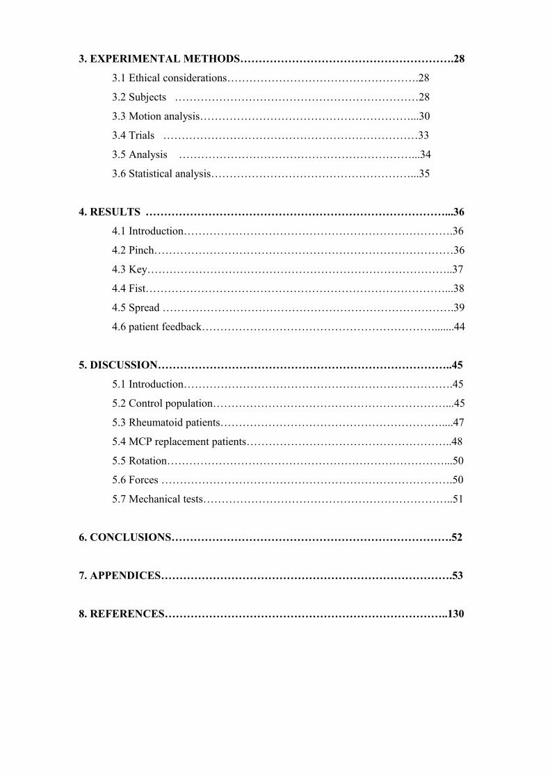