Embed Size (px)
Citation preview

3DS
.CO
M ©
Das
saul
t Sys
tém
es
3DS
.CO
M ©
Das
saul
t Sys
tém
es
The Big GD&T Theory Thomas Allsup
Managing Partner Anida Technologies

3DS
.CO
M ©
Das
saul
t Sys
tém
es
Author: Thomas Allsup • Thomas received his BSME from Oklahoma State University - Go Pokes!
• In 1990, Thomas got his MSME from University of Texas at Arlington.
• Thomas ended his PhD in Mechanical Engineering from UTA as an All-But-Dissertation in 1994.
• Thomas ended his PhD in General Engineering online from Kennedy Western University.
• Thomas has spent 27 years as a design engineer in consumer products, semiconductor devices, and burn-in sockets.
• [email protected] www.anidatech.com twitter: @anidatech.com
3DS
.CO
M ©
Das
saul
t Sys
tém
es
Dedication
This presentation is dedicated to non-PhD mechanical engineer Howard Wolowitz and all the other Howard Wolowitz’s out there!
3DS
.CO
M ©
Das
saul
t Sys
tém
es
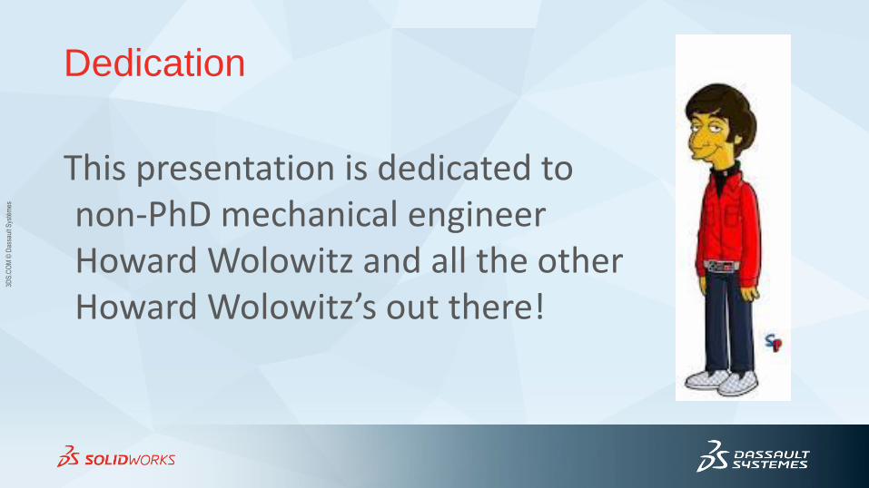
Previously at SolidWorks World
Introduced the learning organizing concept FOPRL:
•Form
•Orientation
•Profile
•Runout
•Location
2009 : How to Spell GD&T
3DS
.CO
M ©
Das
saul
t Sys
tém
es
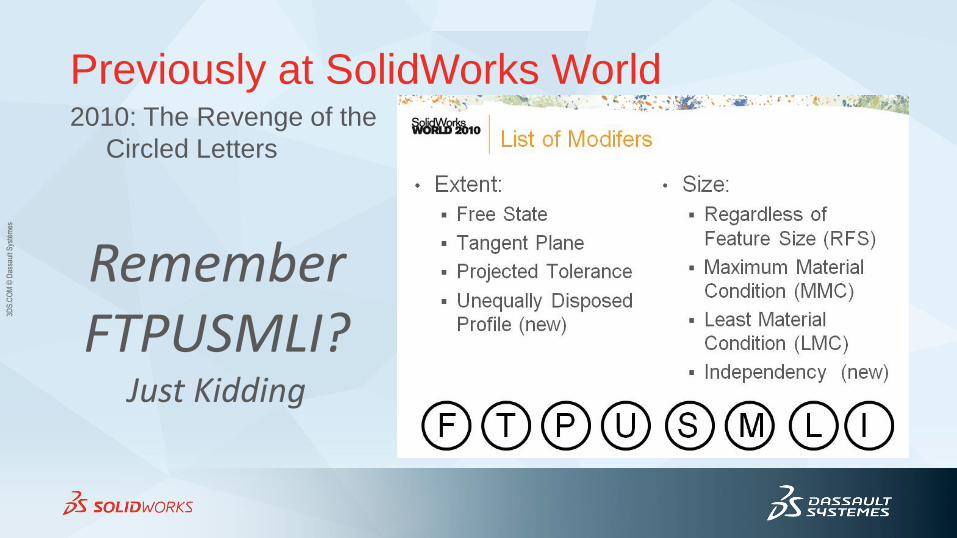
Previously at SolidWorks World
Remember FTPUSMLI?
Just Kidding
2010: The Revenge of the
Circled Letters
3DS
.CO
M ©
Das
saul
t Sys
tém
es
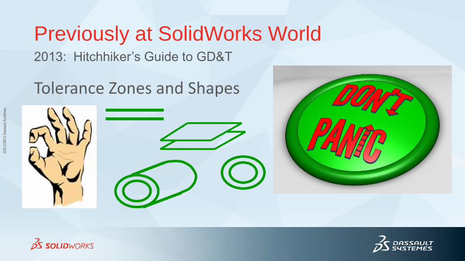
Previously at SolidWorks World
Tolerance Zones and Shapes
2013: Hitchhiker’s Guide to GD&T
3DS
.CO
M ©
Das
saul
t Sys
tém
es
3DS
.CO
M ©
Das
saul
t Sys
tém
es
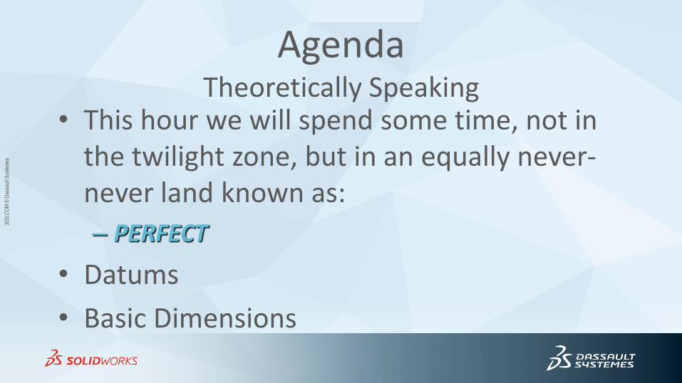
Agenda Theoretically Speaking
• This hour we will spend some time, not in the twilight zone, but in an equally never-never land known as:
– PERFECT
• Datums
• Basic Dimensions
3DS
.CO
M ©
Das
saul
t Sys
tém
es
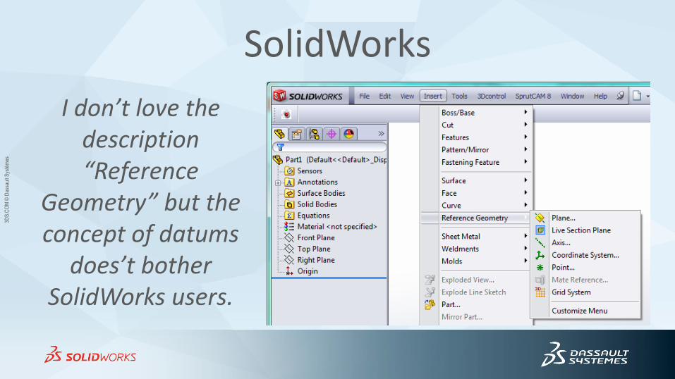
SolidWorks
I don’t love the description “Reference
Geometry” but the concept of datums
does’t bother SolidWorks users.
3DS
.CO
M ©
Das
saul
t Sys
tém
es
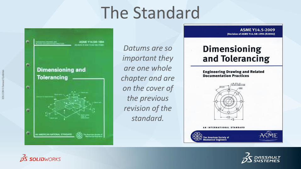
The Standard
Datums are so important they are one whole
chapter and are on the cover of
the previous revision of the
standard.
3DS
.CO
M ©
Das
saul
t Sys
tém
es
Datums • Datums do one simple thing:
– Datums are a way for the part designer to tell the part inspector how to hold and immobilize the part during inspection.
• Datums are a reference for geometric dimensions.
3DS
.CO
M ©
Das
saul
t Sys
tém
es
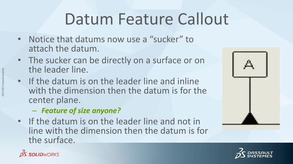
Datum Feature Callout • Notice that datums now use a “sucker” to
attach the datum. • The sucker can be directly on a surface or on
the leader line. • If the datum is on the leader line and inline
with the dimension then the datum is for the center plane. – Feature of size anyone?
• If the datum is on the leader line and not in line with the dimension then the datum is for the surface.
3DS
.CO
M ©
Das
saul
t Sys
tém
es
Individual versus Related Features
• If an Individual feature is a single surface, element, or size feature then no datum is proper or used.
• Related features must use at least one datum.
3DS
.CO
M ©
Das
saul
t Sys
tém
es
Datum Indicators
• Datum indicators with the “suction” cup can indicate a feature of size simply by placing it in line with the leader line.
• Datum indicators indicate features other than features of size by not aligning the datum line with the leader line.
3DS
.CO
M ©
Das
saul
t Sys
tém
es
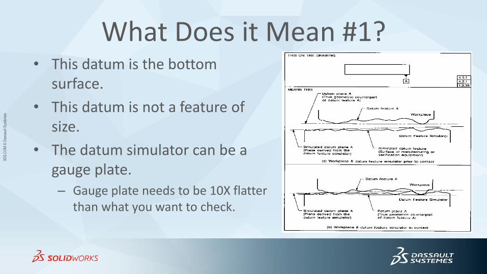
What Does it Mean #1? • This datum is the bottom
surface.
• This datum is not a feature of size.
• The datum simulator can be a gauge plate. – Gauge plate needs to be 10X flatter
than what you want to check.
3DS
.CO
M ©
Das
saul
t Sys
tém
es
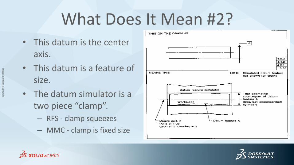
What Does It Mean #2? • This datum is the center
axis.
• This datum is a feature of size.
• The datum simulator is a two piece “clamp”. – RFS - clamp squeezes
– MMC - clamp is fixed size
3DS
.CO
M ©
Das
saul
t Sys
tém
es
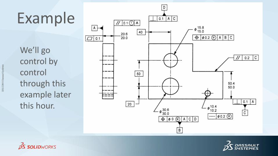
Example
We’ll go control by control through this example later this hour.
3DS
.CO
M ©
Das
saul
t Sys
tém
es
RFS • A datum that is designated regardless of the feature
size can mean a couple of things.
• If the datum isn’t a feature of size or simply a surface then it means you lay the datum on a surface plate.
• If the datum is a feature of size then it means that you have to use a “collet” or adjustable surfaces to go make contact with the feature.
3DS
.CO
M ©
Das
saul
t Sys
tém
es
Regardless of Feature Size • This is the default if no modifier is given.
• The tolerance zone is not affected by the actual size of the feature.
• You don’t see the symbol s anymore except in GD&T training sessions.
• Just because you don’t see the symbol doesn’t mean the concept isn’t used all the time.
s
3DS
.CO
M ©
Das
saul
t Sys
tém
es
Maximum Material Condition
• If a datum has the maximum material modifier then that means you use a fixed size gage that is sized to the maximum material size.
• For external dimensions, use the largest dimension. – Thickest plate.
• For internal dimensions, use the smallest value. – Smallest hole.
• The actual parts move around in the MMC datum simulator.
3DS
.CO
M ©
Das
saul
t Sys
tém
es
Least Material Condition
• This one is harder to explain since the datum simulator is “virtual”.
• The actual part can not placed in an actual LMC datum simulator.
• We’ll calculate the Virtual Condition (VC) of modified features later…
3DS
.CO
M ©
Das
saul
t Sys
tém
es
Fixed Versus Floating
• If you use a datum as “regardless of feature size” then the datum simulator must come in contact with the edge(s).
• If you use a datum as “MMC” or “LMC” then the datum simulator is fixed size and the part moves around inside it.
– We use a different name for this: gaging.
3DS
.CO
M ©
Das
saul
t Sys
tém
es
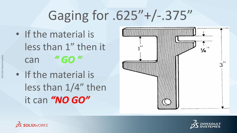
Gaging for .625”+/-.375” • If the material is
less than 1” then it can “ GO ”
• If the material is less than 1/4” then it can “NO GO”
3DS
.CO
M ©
Das
saul
t Sys
tém
es
Reference to Gaging
• Section 1.1.6 Reference to Gaging “This document is not intended to be a gaging standard.”
• Like so many concepts of GD&T, it is hard to discuss datums without mentioning gaging.
• Jedi Mind Trick: – “This is not the gaging standard you are looking for.”
3DS
.CO
M ©
Das
saul
t Sys
tém
es
Rule of Ten
• If you want to measure a feature accurately, you need a tool that is capable of measuring 1/10 the smallest dimension or tolerance.
• Example: To measure a +/-.001” tolerance you need to .0001” resolution caliper.
• The same thing goes for datums and granite slabs.
3DS
.CO
M ©
Das
saul
t Sys
tém
es
Granite Slabs Granite materials are black, grey, and crystal pink, each offered
in three grades:
• AA-Laboratory for precision operation in constant temperature gaging rooms and metrology departments - 25 millionths
• A-Inspection Grade for general quality control applications - 50 millionths
• B-Toolroom for general production checking work throughout the shop - 100 millionths
3DS
.CO
M ©
Das
saul
t Sys
tém
es
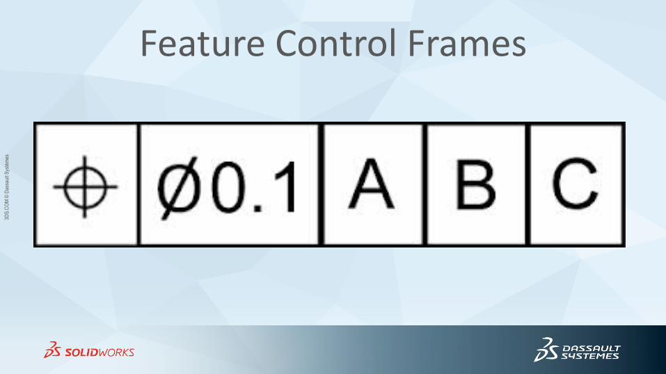
Feature Control Frames
3DS
.CO
M ©
Das
saul
t Sys
tém
es
Points of Contact • A primary datum feature usually has three points of contact
– Don’t use the word must.
• A secondary datum feature usually has two points of contact
– Don’t use the word must.
• A tertiary datum feature usually has one point of contact
– Don’t use the word must.
• The largest surface on a part doesn’t always have to be the primary datum feature.
– The designer dictates primary datum feature.
– Usually it is a good design idea for the largest surface to be the primary datum feature.
3DS
.CO
M ©
Das
saul
t Sys
tém
es
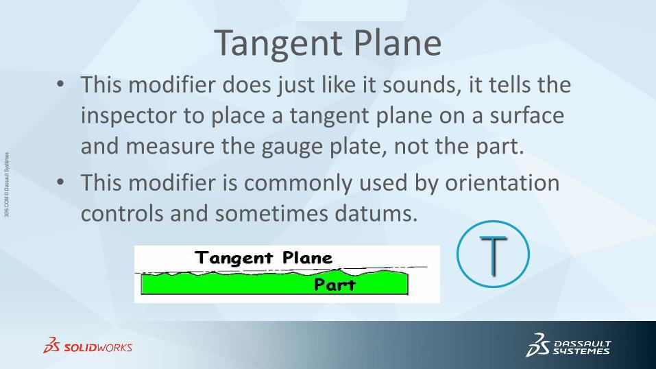
Tangent Plane • This modifier does just like it sounds, it tells the
inspector to place a tangent plane on a surface and measure the gauge plate, not the part.
• This modifier is commonly used by orientation controls and sometimes datums.
T
3DS
.CO
M ©
Das
saul
t Sys
tém
es
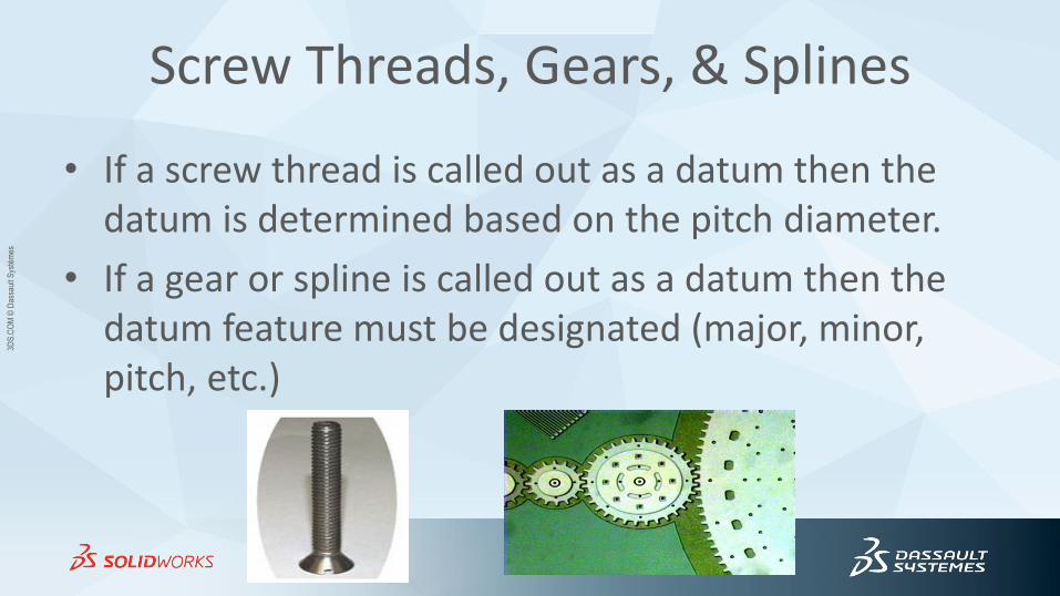
Screw Threads, Gears, & Splines
• If a screw thread is called out as a datum then the datum is determined based on the pitch diameter.
• If a gear or spline is called out as a datum then the datum feature must be designated (major, minor, pitch, etc.)
3DS
.CO
M ©
Das
saul
t Sys
tém
es
Simultaneous Requirements
• When you look at a drawing and see the same datums, in the same order, with the same modifiers then all the geometric tolerances are measured at one time – they are simultaneous requirements unless you place the words “SEP REQT” under the tolerance. – “Same set up”
• When you see the FRTZF and PLTZF show, we get to discuss the addition of “SIM REQT”.
3DS
.CO
M ©
Das
saul
t Sys
tém
es
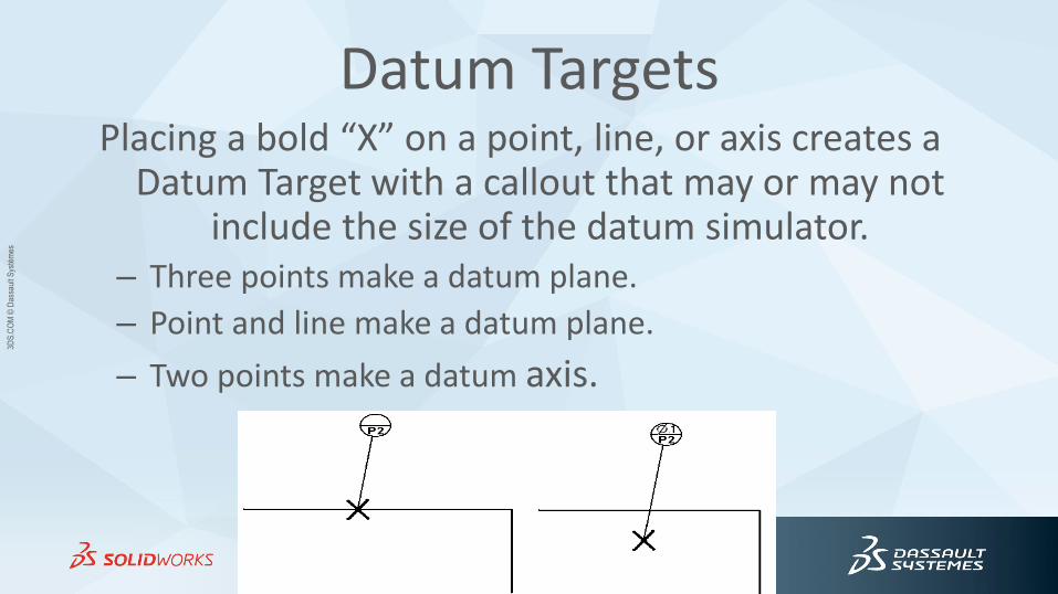
Datum Targets Placing a bold “X” on a point, line, or axis creates a
Datum Target with a callout that may or may not include the size of the datum simulator.
– Three points make a datum plane.
– Point and line make a datum plane.
– Two points make a datum axis.
3DS
.CO
M ©
Das
saul
t Sys
tém
es
Datum Definitions • A Datum is a theoretically exact
• point
• axis
• plane
– derived from the true geometric counterpart of a specified datum feature.
• A datum is the origin from which the location or geometric characteristics of features of a part are established.
3DS
.CO
M ©
Das
saul
t Sys
tém
es
Datum Definitions • Datum Feature: an actual feature of a part that is used to establish a datum.
• Datum Feature Simulator: A surface of adequately precise form (such as a surface plate, a gage surface, or a mandrel) contacting the datum feature(s) and used to establish the simulated datum(s).
– NOTE: Simulated datum features are used as the practical embodiment of the datums during manufacture and inspection.
• Simulated Datum: A point, axis, or plane established by processing or inspection equipment, such as the following simulators: a surface plate, a gage surface, or a mandrel.
• Datum Target: A specified point, line, or area on a part used to establish a datum.
3DS
.CO
M ©
Das
saul
t Sys
tém
es
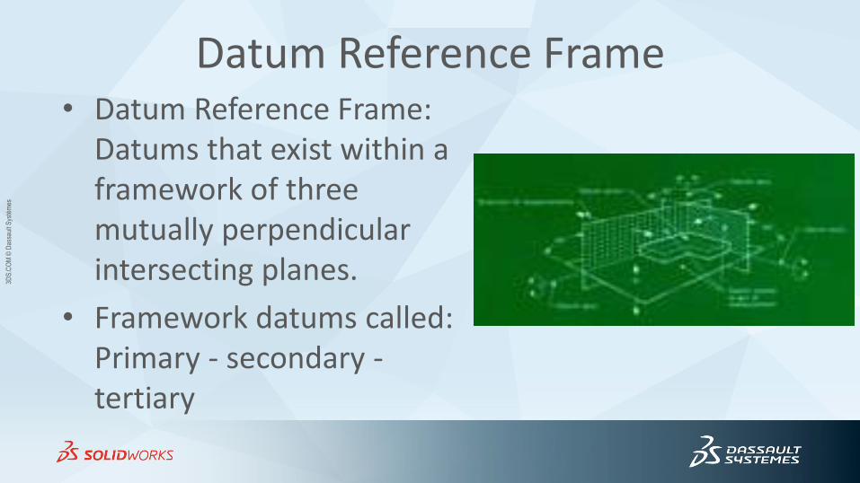
Datum Reference Frame • Datum Reference Frame:
Datums that exist within a framework of three mutually perpendicular intersecting planes.
• Framework datums called: Primary - secondary - tertiary
3DS
.CO
M ©
Das
saul
t Sys
tém
es
Feature Control Frames • Vertical lines between datums in a feature control frame
separate primary – secondary – and tertiary datums.
• Horizontal lines between datums in a feature control frame indicate compound datums.
• Datums are never listed purely based on alphabetical order in feature control frames – they might appear in alphabetical order but they are always “in the desired order
of precedence, from left to right.”
3DS
.CO
M ©
Das
saul
t Sys
tém
es
Clarification of Feature Control Frame
• Draw vertical lines between separate datums: – “Where more than one datum is required, the datum reference
letters (each followed by a material condition symbol where applicable) are entered in separate compartments in the desired order of precedence, from left to right.”
• Draw a horizontal dash between datums to indicate a compound datum. – Pre-ASME Y14.5-1994, the dashes could have meant a datum
callout.
3DS
.CO
M ©
Das
saul
t Sys
tém
es
Missing in Action
• The standard only calls out three letters that cannot be used as datums.
– I, O, or Q
• The standard does not say you have to start with A and go in any particular order.
– I prefer to never use S or Z
3DS
.CO
M ©
Das
saul
t Sys
tém
es
Opinion #1 Can you have datums on a drawing without any other GD&T symbols?
Answer #1: No - Without feature control frames, datums are extraneous information so you should not have them alone on a print.
Answer #2: Yes - Unreferenced datums could be considered “reference dimensions” so they could appear alone on a print.
Answer #3: Yes - Notes can use datum callouts so datums could still appear
on the face of the drawing and their only reference is in the text notes.
Common sense says do not use datums without GD&T.
3DS
.CO
M ©
Das
saul
t Sys
tém
es
Axis of Measurement
• Circularity and cylindricity tolerances do not use datums because they use the features own axis for measurement.
• Circular runout and total runout tolerances use datums as their axis for measurement.
3DS
.CO
M/S
OL
IDW
OR
KS
© D
assa
ult S
ystè
mes
| C
onfid
entia
l Inf
orm
atio
n | 4
/26/
2014
| re
f.: 3
DS
_Doc
umen
t_20
12
41
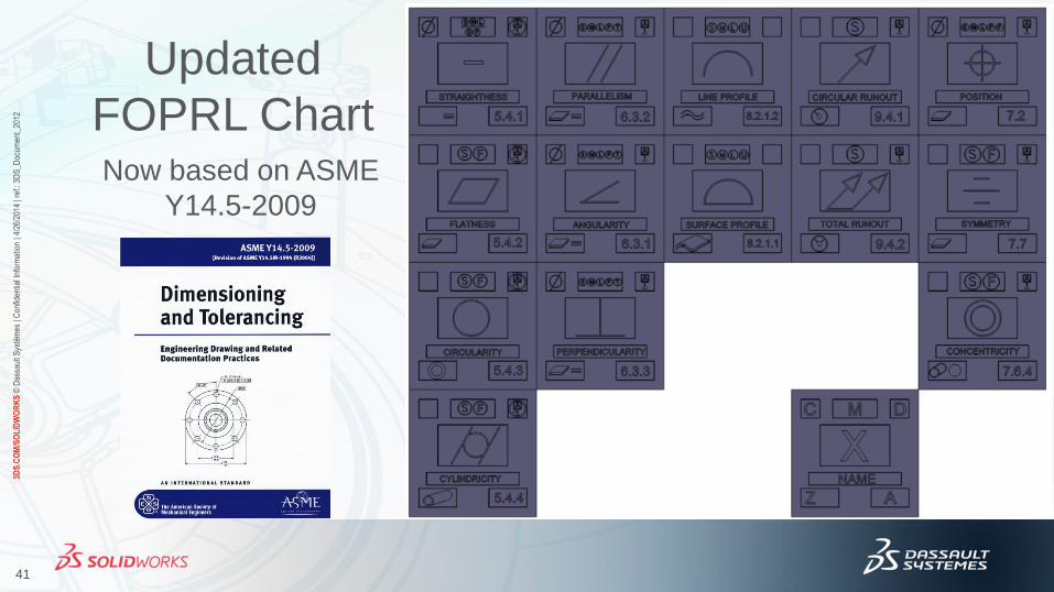
Updated
FOPRL Chart Now based on ASME
Y14.5-2009
3DS
.CO
M ©
Das
saul
t Sys
tém
es
Basic Dimensions
• If you think of datums as a method of immobilizing a part then basic dimensions are just offsets from that reference frame.
• Basic dimensions are boxed dimensions.
• Basic dimensions don’t have tolerances, they are used by other geometric dimensions.
3DS
.CO
M ©
Das
saul
t Sys
tém
es
Basic Dimensions as Offsets
• Our electrical engineering colleagues use a lot of precise equipment that have a small knob to adjust and output up and down.
• This small difference in the setting and the output is known as an “offset”.
• Mechanically speaking, basic dimensions are offsets from the datum target.
3DS
.CO
M ©
Das
saul
t Sys
tém
es
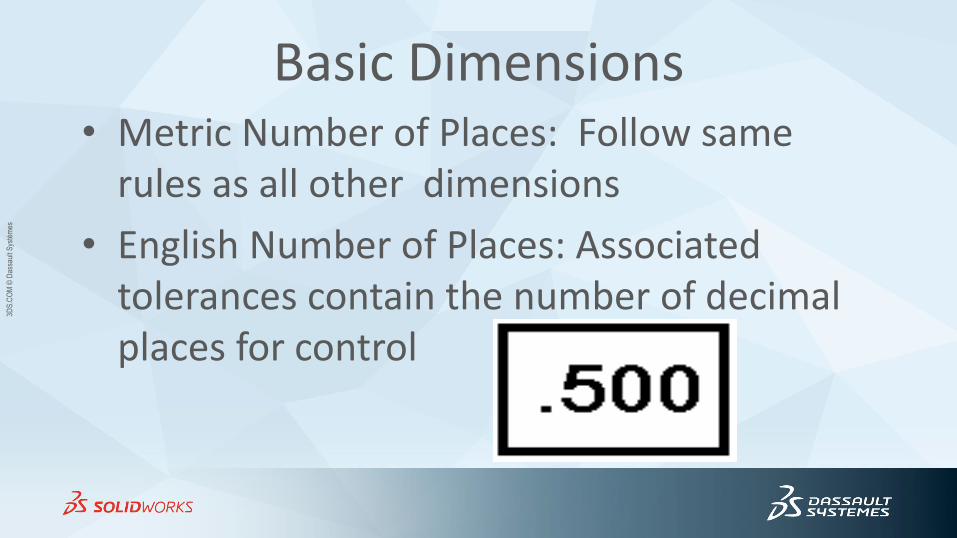
Basic Dimensions • Metric Number of Places: Follow same
rules as all other dimensions
• English Number of Places: Associated tolerances contain the number of decimal places for control
3DS
.CO
M ©
Das
saul
t Sys
tém
es
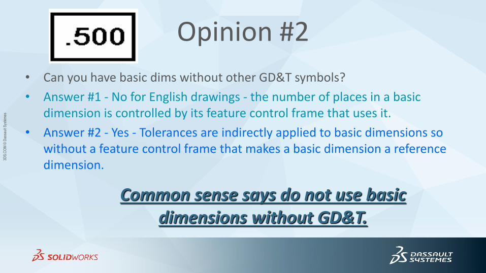
Opinion #2
• Can you have basic dims without other GD&T symbols?
• Answer #1 - No for English drawings - the number of places in a basic dimension is controlled by its feature control frame that uses it.
• Answer #2 - Yes - Tolerances are indirectly applied to basic dimensions so without a feature control frame that makes a basic dimension a reference dimension.
Common sense says do not use basic dimensions without GD&T.
3DS
.CO
M ©
Das
saul
t Sys
tém
es
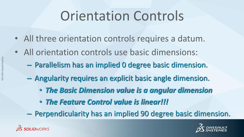
Orientation Controls
• All three orientation controls requires a datum.
• All orientation controls use basic dimensions:
– Parallelism has an implied 0 degree basic dimension.
– Angularity requires an explicit basic angle dimension.
• The Basic Dimension value is a angular dimension
• The Feature Control value is linear!!!
– Perpendicularity has an implied 90 degree basic dimension.
3DS
.CO
M ©
Das
saul
t Sys
tém
es
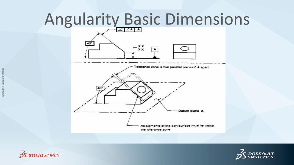
Angularity Basic Dimensions
3DS
.CO
M ©
Das
saul
t Sys
tém
es
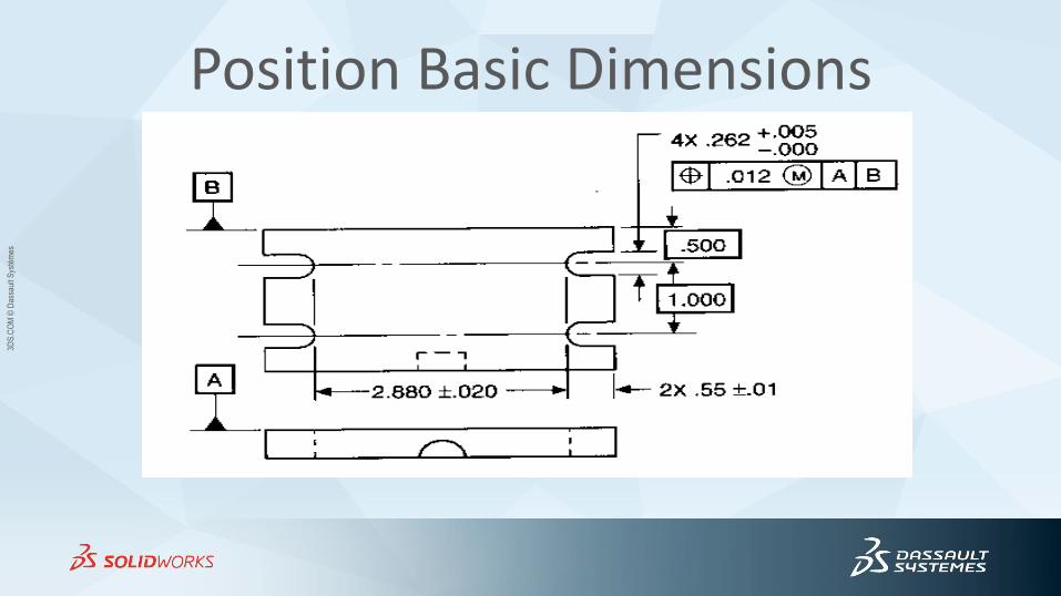
Position Basic Dimensions
3DS
.CO
M ©
Das
saul
t Sys
tém
es
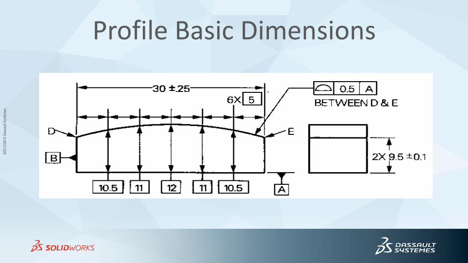
Profile Basic Dimensions
3DS
.CO
M ©
Das
saul
t Sys
tém
es
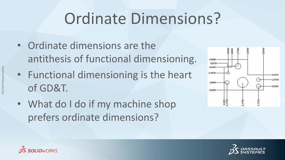
Ordinate Dimensions?
• Ordinate dimensions are the antithesis of functional dimensioning.
• Functional dimensioning is the heart of GD&T.
• What do I do if my machine shop prefers ordinate dimensions?
3DS
.CO
M ©
Das
saul
t Sys
tém
es
Ordinate Notes
• If you have to use ordinate dimensions, then add two notes like: – “All untoleranced dimensions are basic.”
– “All untoleranced holes are located within XXX of true position.”
• You can now skip the note “NONACCUMULATIVE”.
3DS
.CO
M ©
Das
saul
t Sys
tém
es
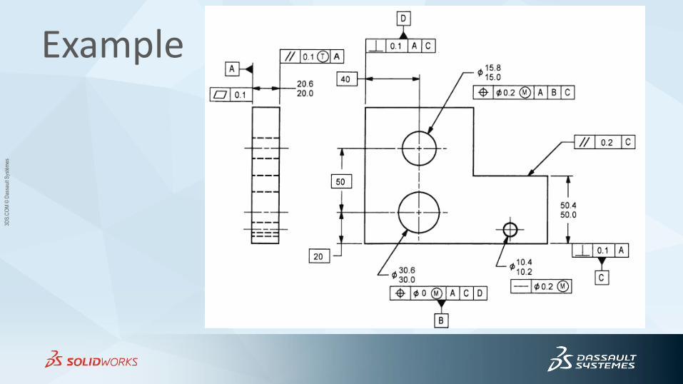
Example
3DS
.CO
M ©
Das
saul
t Sys
tém
es
Datum Review • A Datum is a theoretically exact
• point
• axis
• plane
– derived from the true geometric counterpart of a specified datum feature.
• A datum is the origin from which the location or geometric characteristics of features of a part are established.
3DS
.CO
M ©
Das
saul
t Sys
tém
es
Basic Dimensions Review
• Basic dimensions are used to orient or locate features with respect to datums.
• Basic dimensions are theoretically perfect and have no tolerance on their own.
3DS
.CO
M ©
Das
saul
t Sys
tém
es
Questions?
• GD&T?
• Datums?
• Basic Dimensions?

3DS
.CO
M ©
Das
saul
t Sys
tém
es
Presentation Available Now
Download This Week After SWW2014
• You can find this and other GD&T and technical PowerPoint presentations on our website.
www.anidatech.com
• Proceedings with audio will be available in a month or so from SolidWorks.