Embed Size (px)
Citation preview
THE BEHAVIOUR OF SQUARE SANDWICH PANEL PART I: UNDER STATIC LOADING 1
Jurnal Teknologi, 47(A) Dis. 2007: 1–18© Universiti Teknologi Malaysia
THE BEHAVIOUR OF SQUARE SANDWICH PANELPART I: UNDER STATIC LOADING
AMRAN ALIAS1, NOR AZLAN AHMAD NOR2 & MOHD RADZAI SAID3
1&2Faculty of Mechanical Engineering, Universiti Teknologi Malaysia, 81310 Johor, Malaysia.E-mail: [email protected]
3 Faculty of Mechanical Engineering, Universiti Teknikal Malaysia Melaka, Locked Bag 1200, 75450Melaka, Malaysia.
Abstract. This series of papers on behaviour of square sandwich panel consists of two parts. In partI, the performance and behaviour of the square sandwich panel under static loading was first examined.The sandwich panel was centrally loaded by using hemispherical and flat indenters on their respectivesupport units. The panel materials used specifically for this project are mild steel skin and PVC foamnamely R55 and polyurethane (PU) foam cores. The aim of this study is to obtain experimentalevidence of the failure modes of square sandwich panels under concentrated load at the centre of panels,simply supported at the four edge corners for the square panel. After static tests, the whole curves foreach panel were determined. The relation between the observed damage development, the property ofdegradation during the static test of the panels was investigated. In part II, the dynamic tests will beconducted in order to determine the performance, behaviour, effect of foam’s type and the correlationbetween input energy from static and dynamic tests.
Keywords: Square sandwich panel, PU foam, PVC foam (R55), failure modes
Abstrak. Kajian mengenai panel apit segi empat terdiri daripada dua bahagian. Dalam bahagianpertama, prestasi dan kelakuan panel apit segi empat yang dikenakan beban statik dikaji. Panel apit inisokong oleh unit sokongan dan dikenakan bebanan dibahagian tengahnya dengan menggunakanpenakuk separa bulat dan penakuk rata. Panel apit spesifik yang digunakan untuk projek ini ialahkepingan keluli lembut, foam PVC yang dinamakan R55 dan teras daripada busa poli uretana (PU).Tujuan kajian ini adalah untuk mendapatkan bukti secara eksperimen tentang corak serta jenis kegagalanpanel apit segi empat yang dikenakan beban tumpu di tengah-tengahnya dan disokong pada setiapbucunya. Selepas ujian statik dilakukan, lengkungan bagi setiap panel ditentukan. Hubungan antarapertumbuhan kerosakan dan kelakuan kerosakan semasa ujian statik ke atas panel dikaji. Dalambahagian kedua, ujian dinamik dijalankan untuk menentukan prestasi, kelakuan, dan kesan bagi jenisbusa serta hubungan antara tenaga masukan daripada ujian statik dan dinamik.
Kata kunci: Panel apit segi empat, foam PU, foam PVC (R55), mod kegagalan
1.0 INTRODUCTION
A sandwich panel can be characterized as a composite that constitutes of two facesseparated by and linked to a core that is less stiff and less dense. The faces and thecore are usually connected by adhesive that provides structural continuity across the
JT47Adis07[01].pmd 06/10/2008, 16:361
AMRAN, NOR AZLAN & MOHD RADZAI2
depth panel. The important role of the faces of a sandwich panel is to bear tensile,compressive, flexural and shear stress resultants that act parallel to the plane of thepanel. Faces may also act to distribute localized loads and reactions to the softer andweaker core. The core of a sandwich panel separates the faces and holds them insteady position. It gives the shear load path between the faces and together with skin, itcarries loads or reaction that are applied normal to the plane of the panel. An amplerange of skin and core materials are available in large number of combinations. It canbe a beam, a panel or any other special shape. The skin can be of metal, wood,plastic, FRP composites or any other structural material. Likewise, cores may be madeof honeycomb, corrugated or foamed cellular materials. Considerably good structuralintegrity with less weight. It has been very useful in offshore panel structure and inaircraft industry where minimizing weight is important.
The development of study on sandwich plates was initiated by the study of monolithicplates. The collapse loads of rigid-plastic plates are determined by limit analysis. Theearly works on the general theory of limit analysis were developed by Onat et al. [1] asa major component of the theoretical approach of perfectly plastic solid in many fields.Later, comprehensive study on the relationship of load and displacement of plates,namely square and circular, with different boundary condition were given in fewreferences [2-4]. The perfect-plastic theory derives its simplicity from two assumptions;that the material is perfectly plastic i.e. no strain hardening and that there is no significantchanges in geometry which would affect the equilibrium equation of structure.According to this theory, the plastic collapse of structure takes place at constant loadi.e. no deformation takes place until a ‘limit’ is reached which followed by continuousdeformation. In general, it requires a plastic deformation mechanism to be formed.When the limit is reached, bending deformation is concentrated at yield hinges. Thedeformation of the structure becomes possible only when yield hinges have developedseveral times to transform the structure into mechanism.
When the ratio of plate thickness to plate radius is relatively small, in order for theplastic deformation to continue, once initiated, presumably some increase in appliedload would be required. These effects are due to membrane action. At the initialstages of deformation of the plates, bending action always predominates over membraneaction. Consequently, near to collapse or deformation, the associated stretching at themiddle cannot take place due to the absent of deformation.
The main purpose of this analysis is finding the flow limit under given types ofloading. The load intensity at the flow limit is called the load carrying capacity ofstructure. The load carrying capacity of perfectly plastic circular plates has beendiscussed by Hopkins and Prager [5]. In these analysis, a limiting condition for thestrength of the material has to be assumed in order to obtain a collapse load; the mostcommonly criteria used are Tresca and Von Mises. The application of these criteria toyielding of plates is discussed by Hopkins [6]. The problems of plate with simplysupported or built in at edge and subjected to simple symmetric loading are discussedby Hopkins and Prager [5] using the Tresca yield condition.
JT47Adis07[01].pmd 06/10/2008, 16:362
THE BEHAVIOUR OF SQUARE SANDWICH PANEL PART I: UNDER STATIC LOADING 3
Calladine [7] proposed a new promising approach to simplify the analysis of largedeflection of plates in plastic range. The idea is basically to trace approximately thedeflection history of a plate by means of succession of upper bound calculation, madeby considering the structure to be three-dimensional body of perfectly plastic material.His theoretical approach has been particularly chosen for the present study as thetheoretical approach for comparison of the experimental works.
In square sandwich panels study, the theory of elastic bending and buckling thattakes transverse shear effect in the core into account appears to have been developedby several authors [8]. They published a series of reports on the elastic bending andbuckling of isotropic sandwich panels. Allen [9] presented a comprehensive discussionon the general sandwich construction. He also discussed sandwich panels subjectedto uniformly distributed load over the whole area of the top skin. The analysis ofsimply supported sandwich panel with centrally point loading is deduced from aboveas a local distributed over a circle (indenter size) at the centre of the top skin.
The literature about wrinkling problem is less than that bending problem. Gough,Elam and De Bruyne [10] were the first to analyze the problem in the strut stabilitywhich is applicable to anti-symmetrical wrinkling of sandwich struts. Hoff and Mautner[11] made the same kind of analysis for symmetrical wrinkling of sandwich struts. Theeffect of initial irregularities on wrinkling behaviour of the faces in relation to the tensilestrength of adhesive was first discussed by Wan [12].
Type of failure modes of sandwich panels were discussed by Ashby and Gibson[13]. To remain mathematical simplicity, they focus the study on sandwich beams.Swanson and Kim [14], Mines and Alias [15], Traintafillou and Gibson [16] and a fewother authors as well as Allen [9] conducted works on failures of sandwich beams.
Sandwich beams subjected to bending can fail in several ways. The tension andcompression faces may fail uniaxially, by either yielding or fracturing, and thecompression face may buckle locally, by either wrinkling or dimpling. Wrinklinginvolves local buckling of the face into the core, causing compression of the core. Thecore also can fail. The most common mode of core failure is shear [17-19]. Otherpossible modes are tensile or compressive yield and if the core made a brittle material,tensile fracture. Finally, the bond between the face and the core can fail; since resinadhesives are usually brittle, debonding is by brittle fracture [20].
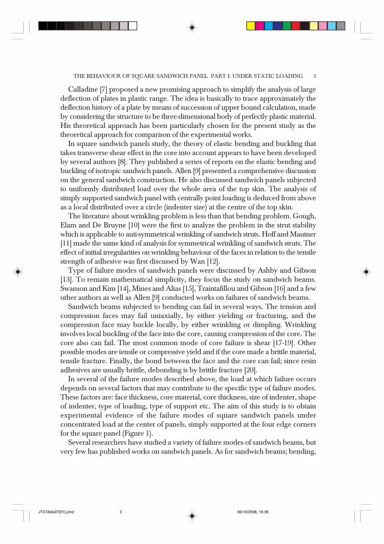
In several of the failure modes described above, the load at which failure occursdepends on several factors that may contribute to the specific type of failure modes.These factors are: face thickness, core material, core thickness, size of indenter, shapeof indenter, type of loading, type of support etc. The aim of this study is to obtainexperimental evidence of the failure modes of square sandwich panels underconcentrated load at the center of panels, simply supported at the four edge cornersfor the square panel (Figure 1).
Several researchers have studied a variety of failure modes of sandwich beams, butvery few has published works on sandwich panels. As for sandwich beams; bending,
JT47Adis07[01].pmd 06/10/2008, 16:363
AMRAN, NOR AZLAN & MOHD RADZAI4
core shear, and face wrinkling was described by Allen [9], Ashby and Gibson [13],Sayight [21] and Platema [22]. The failure modes are discussed to great depth byAllen [9] and, Ashby and Gibson [13] in their books. Almost all the theoretical arefound to be formulae in elastic regime and currently are focusing into plastic regime.Previous literatures will be reviewed and the theoretical basis chosen are presented.The technical properties of the materials used and the test under taken will be described.It also discuss the method used for manufacturing the sandwich panels and theexperimental set up and the procedures under taken in static tests of the sandwichpanels. The results of the static experimental tests will be discussed in respectivelywith emphasis on illustrating the failure modes of the square sandwich panels.
2.0 THEORETICAL APPROACH
Consider a circular plate perfectly plastic material, radius r and thickness h, simplysupported at its edge and carrying a central load P. For simplicity, P is treated as apoint load, but it must be borne in mind that this is an idealization of a load spreadover a region, sufficiently large for failure not to occur locally.
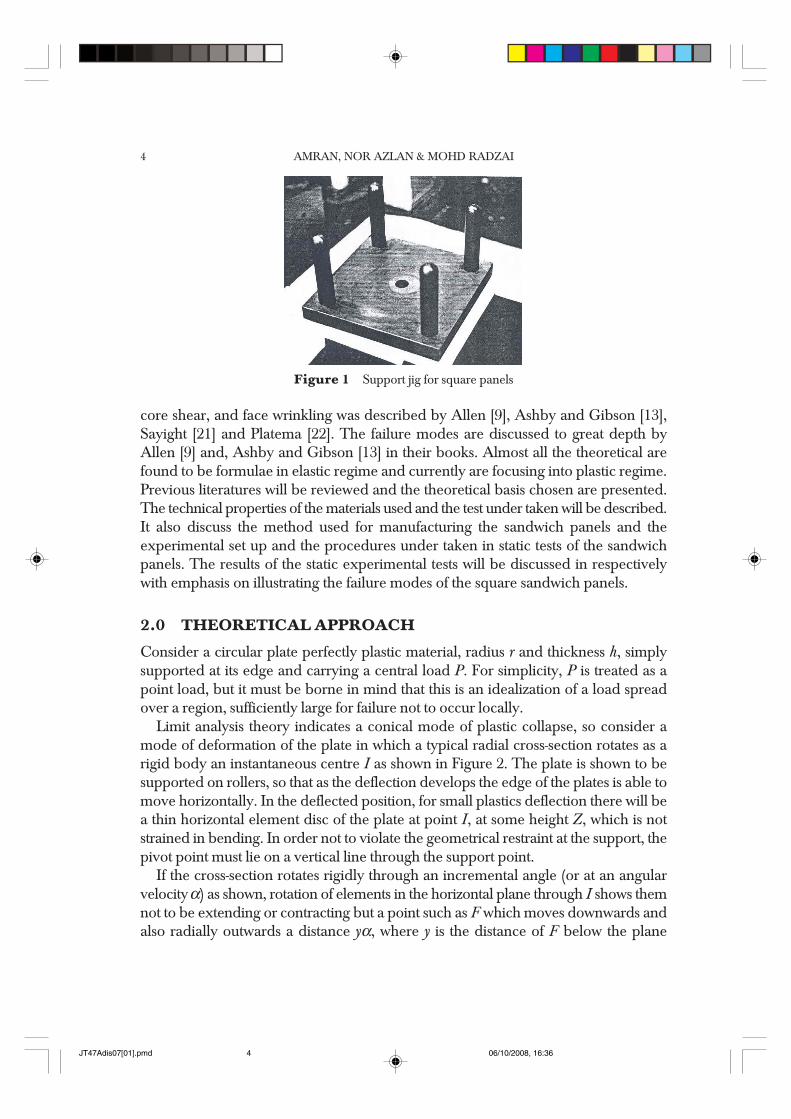
Limit analysis theory indicates a conical mode of plastic collapse, so consider amode of deformation of the plate in which a typical radial cross-section rotates as arigid body an instantaneous centre I as shown in Figure 2. The plate is shown to besupported on rollers, so that as the deflection develops the edge of the plates is able tomove horizontally. In the deflected position, for small plastics deflection there will bea thin horizontal element disc of the plate at point I, at some height Z, which is notstrained in bending. In order not to violate the geometrical restraint at the support, thepivot point must lie on a vertical line through the support point.
If the cross-section rotates rigidly through an incremental angle (or at an angularvelocity α) as shown, rotation of elements in the horizontal plane through I shows themnot to be extending or contracting but a point such as F which moves downwards andalso radially outwards a distance yα, where y is the distance of F below the plane
Figure 1 Support jig for square panels
JT47Adis07[01].pmd 06/10/2008, 16:364
THE BEHAVIOUR OF SQUARE SANDWICH PANEL PART I: UNDER STATIC LOADING 5
defined by I, indicated in Figure 2. If y is positive, the element will be subjected tocompressive hoop yield stress σo and if it is negative to tensile hoop stress. The hoopof material corresponding to F, therefore, undergoes a circumferential strain increment,
θαε =
yx
(1)
where x is the perpendicular distance from the axis of the plate. If dA is a small cross-sectional area associated with point F, the volume of the corresponding hoop isdV = 2π × dA, so the plastic work dissipated in the elementary hoop is given by,
θσ πσ α= 2o oe dV y dA (2)
where σo is the yield stress of the material in tension or compression. Integrating overthe radial cross-section and equating to the work done by the load P in its correspondingdescent,
2 oPR y dAα πσ α= (3)
In the integration, area is regarded as essentially positive, and the modulus sign isintroduced because the work done in either tensile or compressive plastic deformationis positive.
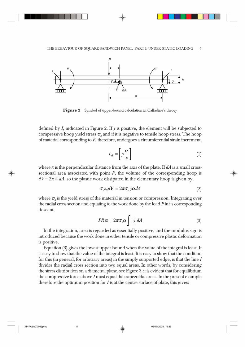
Equation (3) gives the lowest upper bound when the value of the integral is least. Itis easy to show that the value of the integral is least. It is easy to show that the conditionfor this (in general, for arbitrary areas) in the simply supported edge, is that the line Idivides the radial cross section into two equal areas. In other words, by consideringthe stress distribution on a diametral plane, see Figure 3, it is evident that for equilibriumthe compressive force above I must equal the trapezoidal areas. In the present exampletherefore the optimum position for I is at the centre surface of plate, this gives:
Figure 2 Symbol of upper-bound calculation in Calladine’s theory
dAF
P
Iα
a
y Zh
Iα
∫
JT47Adis07[01].pmd 06/10/2008, 16:365
AMRAN, NOR AZLAN & MOHD RADZAI6
2
2ohy dA R= (4)
so Equation (3) gives:
πσ=2
2o
oh
P (5)
This is precisely the result given by the limit analysis theory, viz. P = 2πMo where Mois the full plastic bending moment per unit length and h is the thickness of the beam.
σ=2
4o
o oh
M (6)
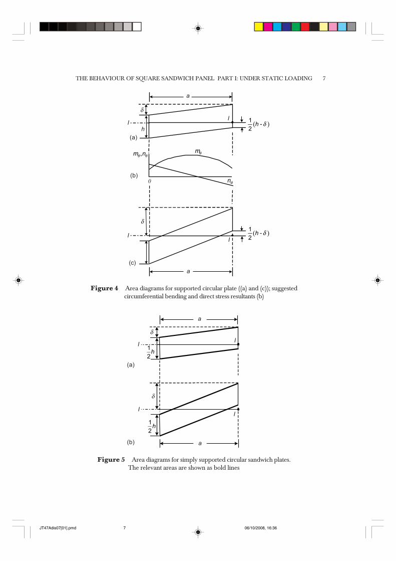
Calculation of the minimum upper bound is in principle no more difficult when theplate has deformed into a shallow cone. When the centre of the plate has descended adistance d < h, the area diagram is shown in Figure 4(a). Performing the integration
∫ y dA by taking first moment of rectangular and triangle areas about the current axisI-I’, and summing, we find that for d/h < 1.0,
= +
211
3od
P Ph (7)
For central deflection larger than the thickness of the plate the appropriate areadiagram is shown in Figure 4(c); so for d/h > 1.0 it leads to the result:
= + 13o
d dP P
h h (8)
In sandwich panel analysis, it is a matter to adapt the area method to deal with asandwich of this sort. For a conical mode of deformation the appropriate diagram forδ < h/2 and δ > h/2 respectively, are shown in Figure 5.
Figure 3 Diametral plane
w
Z I’ I
R
h0-Z
∫A
JT47Adis07[01].pmd 06/10/2008, 16:366
THE BEHAVIOUR OF SQUARE SANDWICH PANEL PART I: UNDER STATIC LOADING 7
Figure 4 Area diagrams for supported circular plate ((a) and (c)); suggestedcircumferential bending and direct stress resultants (b)
Figure 5 Area diagrams for simply supported circular sandwich plates.The relevant areas are shown as bold lines
(a)
a
II
( )�
��
θ�
θ�
,θ θ� �
h
δ
0
δ
(b)
(c)
II
a
�
��
a
a
I
II
I
δ
δ
( )�
��
�
��
(a)
(b)
JT47Adis07[01].pmd 06/10/2008, 16:367
AMRAN, NOR AZLAN & MOHD RADZAI8
The equal area rule still applies but does not determine uniquely the position ofI for s < h/2, for which we find:
δδ
= + 1
4oh
P Ph
(9)
3.0 MATERIALS, PREPARATION OF SAMPLES, TESTEQUIPMENT AND PROCEDURES
3.1 Materials
Materials selection for the sandwich construction is constrained by the applicationrequirement, availability and cost. In this project, steel skin and two different types ofcellular foam cores one PU foam and one PVC foam are used. Polyester resin wasselected as the adhesive between the skin and the core. The specifications of thematerials used in sandwich panel are:
(a) Skin: Mild steel sheet metal of thickness 0.9 mm.(b) Foams: (i) Cellular foam closed cell of rigid PVC foam sheet namely R55, sheet
thickness of 25 mm and density of 61 kg/m3.(ii) Polyurethane foam sheet namely PU foam, sheet thickness of
25 mm and density of 30 kg/m3.(c) Resin: Scott Bader, Crystic 491 PA ( preaccelerated chemical resistant, isophthalic
polyester resin).(d) Hardener: Catalyst, methyl ethyl ketone 50% in phlegmatize (1% proportion).
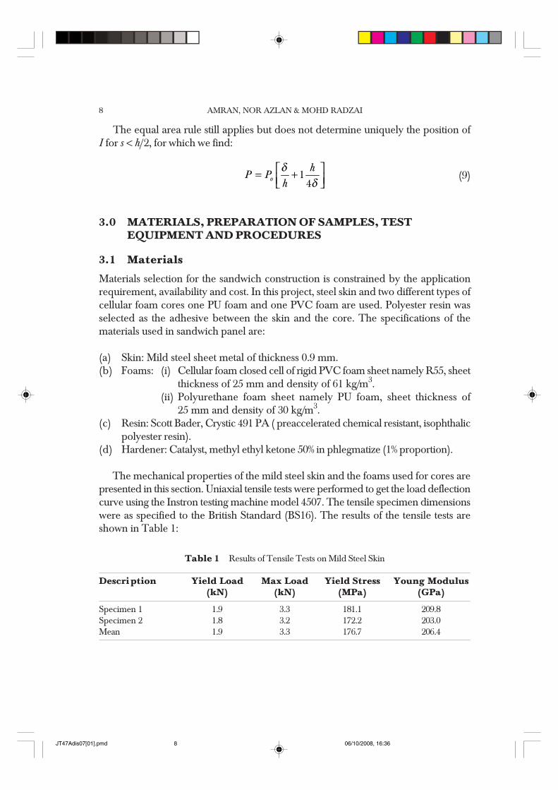
The mechanical properties of the mild steel skin and the foams used for cores arepresented in this section. Uniaxial tensile tests were performed to get the load deflectioncurve using the Instron testing machine model 4507. The tensile specimen dimensionswere as specified to the British Standard (BS16). The results of the tensile tests areshown in Table 1:
Table 1 Results of Tensile Tests on Mild Steel Skin
Description Yield Load Max Load Yield Stress Young Modulus(kN) (kN) (MPa) (GPa)
Specimen 1 1.9 3.3 181.1 209.8Specimen 2 1.8 3.2 172.2 203.0Mean 1.9 3.3 176.7 206.4
JT47Adis07[01].pmd 06/10/2008, 16:368
THE BEHAVIOUR OF SQUARE SANDWICH PANEL PART I: UNDER STATIC LOADING 9
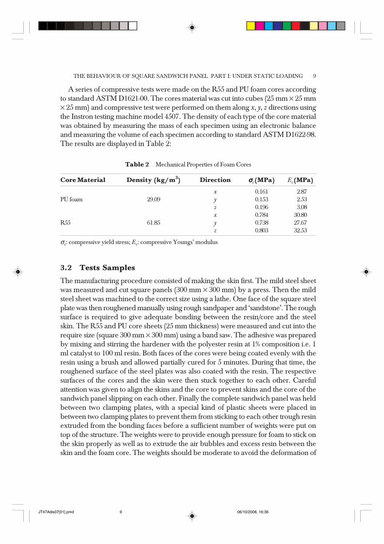
A series of compressive tests were made on the R55 and PU foam cores accordingto standard ASTM D1621-00. The cores material was cut into cubes (25 mm × 25 mm× 25 mm) and compressive test were performed on them along x, y, z directions usingthe Instron testing machine model 4507. The density of each type of the core materialwas obtained by measuring the mass of each specimen using an electronic balanceand measuring the volume of each specimen according to standard ASTM D1622-98.The results are displayed in Table 2:
Table 2 Mechanical Properties of Foam Cores
Core Material Density (kg/m3) Direction σσσσσc(MPa) Ec(MPa)
x 0.161 02.87PU foam 29.09 y 0.153 02.53 z 0.196 03.08
x 0.784 30.80R55 61.85 y 0.738 27.67 z 0.803 32.53
σc: compressive yield stress; Ec: compressive Youngs’ modulus
3.2 Tests Samples
The manufacturing procedure consisted of making the skin first. The mild steel sheetwas measured and cut square panels (300 mm × 300 mm) by a press. Then the mildsteel sheet was machined to the correct size using a lathe. One face of the square steelplate was then roughened manually using rough sandpaper and ‘sandstone’. The roughsurface is required to give adequate bonding between the resin/core and the steelskin. The R55 and PU core sheets (25 mm thickness) were measured and cut into therequire size (square 300 mm × 300 mm) using a band saw. The adhesive was preparedby mixing and stirring the hardener with the polyester resin at 1% composition i.e. 1ml catalyst to 100 ml resin. Both faces of the cores were being coated evenly with theresin using a brush and allowed partially cured for 5 minutes. During that time, theroughened surface of the steel plates was also coated with the resin. The respectivesurfaces of the cores and the skin were then stuck together to each other. Carefulattention was given to align the skins and the core to prevent skins and the core of thesandwich panel slipping on each other. Finally the complete sandwich panel was heldbetween two clamping plates, with a special kind of plastic sheets were placed inbetween two clamping plates to prevent them from sticking to each other trough resinextruded from the bonding faces before a sufficient number of weights were put ontop of the structure. The weights were to provide enough pressure for foam to stick onthe skin properly as well as to extrude the air bubbles and excess resin between theskin and the foam core. The weights should be moderate to avoid the deformation of
JT47Adis07[01].pmd 06/10/2008, 16:369
AMRAN, NOR AZLAN & MOHD RADZAI10
foam core. A weights of approximately 5 kg was used for panels with 25 mm thick PUfoam.
3.3 Static Test
Static tests were carried out first to determine the energy required to produce certainfailure modes. The central loading of the square panels using hemispherical and flatindenters was carried out at a crosshead speed of 2 mm/sec on their respective supportunits. The equipments that were required to do the best were a computer controlledInstron testing machine model 4500, LVDT (displacement transducer) and X-Y plotter.The parameters measured in this test were the load applied (kN), top and bottom skindisplacement (mm). Basically, the sandwich specimen was placed on top the supportjig and the indenter would give the required force, which was supplied by the Instronmachine, to the centre of the top skin of the specimen. Forcing the indenter, whichwas originally placed just on the top skin which was selected as the zero-basis ofdisplacement, to go down at the certain rate (2 mm/min) would cause the centre partof the sandwich specimen to deflect downwards too. A very careful visual observationon the types of failure modes occurred during the test was made. At the moment theproject was done, the Instron machine can only captured two signal simultaneouslynamely top skin displacement (mm) and the force (kN) required. Thus, an LVDThad to be used to measured the third signal i.e. bottom skin displacement. This LVDTwas connected to the X-Y plotter to get displacement profile on a graph paper. Thesignal captured by the Instron testing machine i.e. indenter/top skin displacement, theforce values and the signal captured by the LVDT on the graph paper were then beingtransferred to a computer package to get the results be summarized as in Figure 8 -11.
4.0 RESULTS OF STATIC TESTS
4.1 Experimental Results on The Skins
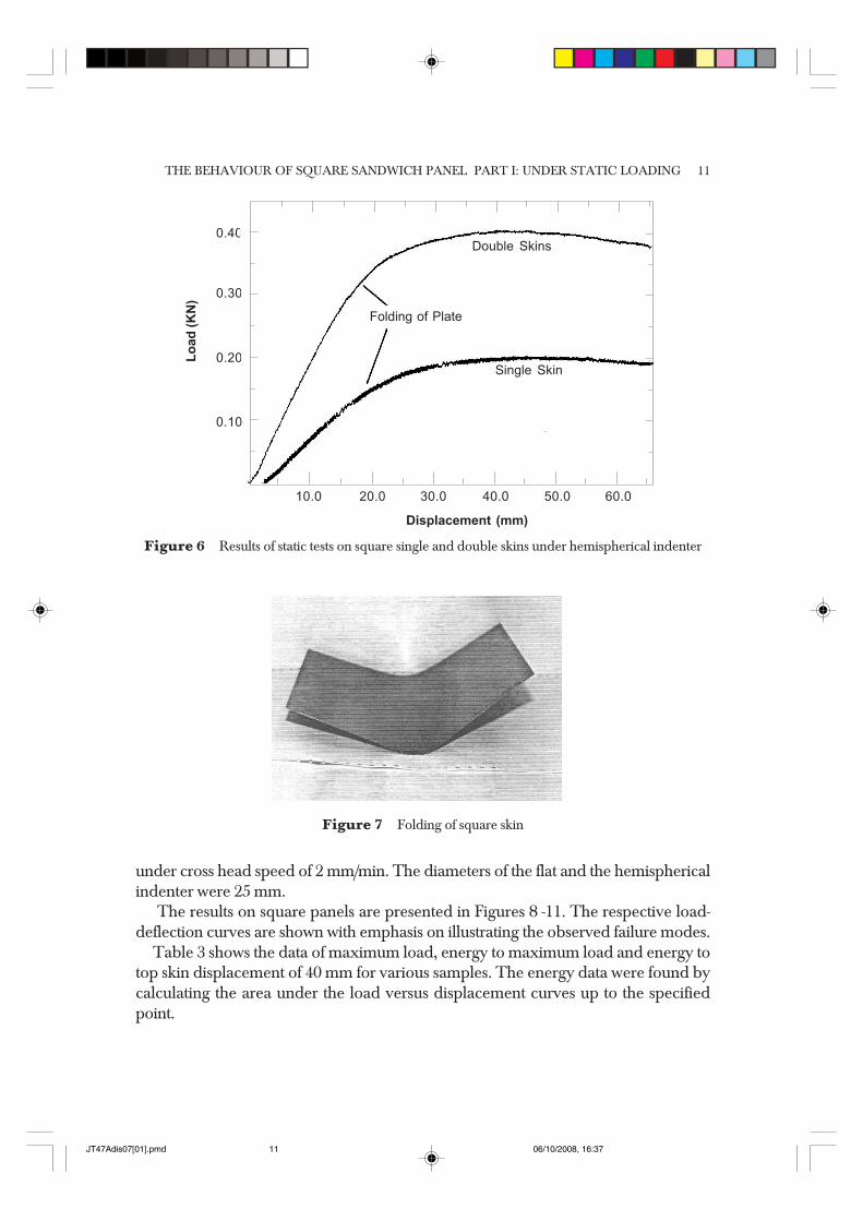
The static tests on single and double skins were performed on the square specimens.The results are presented in Figure 6.
In the square specimens, the main type of failure mode for plate finally folded intoa ‘V’ canal shape (Figure 7).
4.2 Experimental Results on Sandwich Panels
In this project, four quasi-static tests on sandwich panels were performed. Two wereusing PU foam core and the other two were using R55 core. Then, one of the specimensthat were using PU foam was loaded with flat indenter and the other one withhemispherical indenter and so thus the R55 specimen. All of the tests were carried out
JT47Adis07[01].pmd 06/10/2008, 16:3610
THE BEHAVIOUR OF SQUARE SANDWICH PANEL PART I: UNDER STATIC LOADING 11
under cross head speed of 2 mm/min. The diameters of the flat and the hemisphericalindenter were 25 mm.
The results on square panels are presented in Figures 8 -11. The respective load-deflection curves are shown with emphasis on illustrating the observed failure modes.
Table 3 shows the data of maximum load, energy to maximum load and energy totop skin displacement of 40 mm for various samples. The energy data were found bycalculating the area under the load versus displacement curves up to the specifiedpoint.
Figure 6 Results of static tests on square single and double skins under hemispherical indenter
Figure 7 Folding of square skin
0.40
0.30
0.20
0.10
Lo
ad
(K
N)
Displacement (mm)
Folding of Plate
Single Skin
Double Skins
10.0 20.0 30.0 40.0 50.0 60.0
JT47Adis07[01].pmd 06/10/2008, 16:3711
AMRAN, NOR AZLAN & MOHD RADZAI12
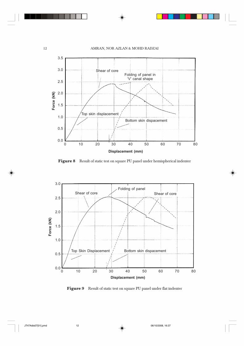
Figure 8 Result of static test on square PU panel under hemispherical indenter
Figure 9 Result of static test on square PU panel under flat indenter
10 20 30 40 50 60 70 80
Displacement (mm)
Top skin displacement
Bottom skin dispacement
3.5
3.0
2.5
2.0
1.5
1.0
0.5
0.0
Fo
rce (
kN
)
0
Folding of panel in‘V’ canal shape
Shear of core
10 20 30 40 50 60 70 80
Displacement (mm)
Top Skin Displacement
3.0
2.5
2.0
1.5
1.0
0.5
0.0
Fo
rce (
kN
)
0
Folding of panelShear of core Shear of core
Bottom skin dispacement
JT47Adis07[01].pmd 06/10/2008, 16:3712
THE BEHAVIOUR OF SQUARE SANDWICH PANEL PART I: UNDER STATIC LOADING 13
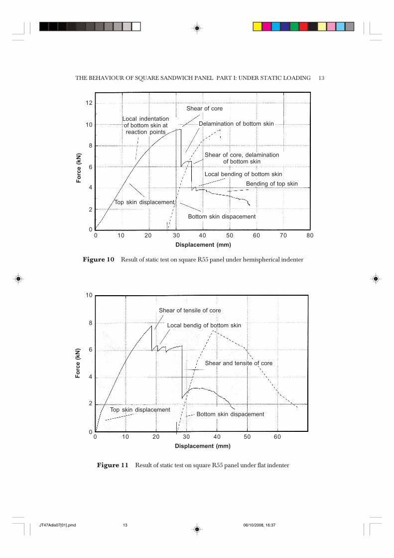
Figure 11 Result of static test on square R55 panel under flat indenter
Figure 10 Result of static test on square R55 panel under hemispherical indenter
Top skin displacement
Bottom skin dispacement
Delamination of bottom skin
Shear of core
Local indentationof bottom skin atreaction points
Shear of core, delaminationof bottom skin
Local bending of bottom skin
Bending of top skin
10 20 30 40 50 60 70 80
12
10
8
6
4
2
0
Fo
rce (
kN
)
0
Displacement (mm)
10
8
6
4
2
0
Fo
rce (
kN
)
10 20 30 40 50 600
Displacement (mm)
Top skin displacementBottom skin dispacement
Shear of tensile of core
Shear and tensite of core
Local bendig of bottom skin
JT47Adis07[01].pmd 06/10/2008, 16:3713
AMRAN, NOR AZLAN & MOHD RADZAI14
4.3 Failure Modes on Square Panels in Static Tests
The common failure modes observed during the static tests on square panels are:
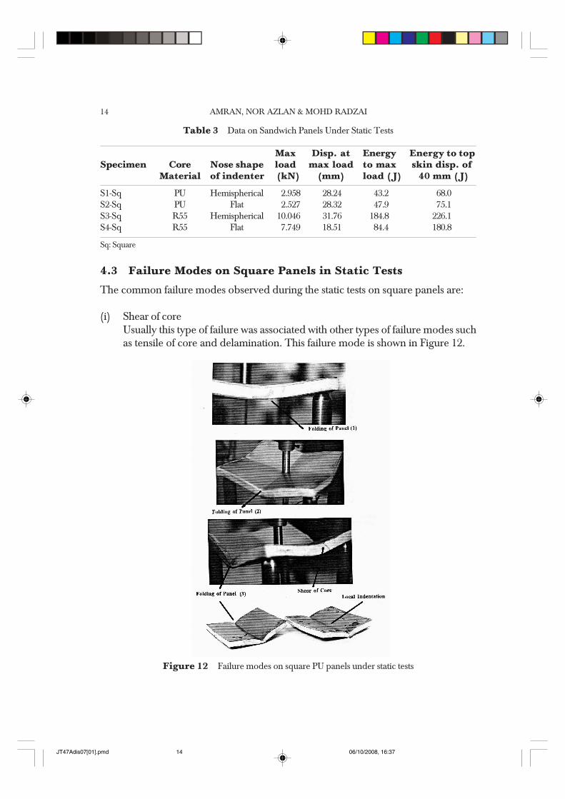
(i) Shear of coreUsually this type of failure was associated with other types of failure modes suchas tensile of core and delamination. This failure mode is shown in Figure 12.
Table 3 Data on Sandwich Panels Under Static Tests
Max Disp. at Energy Energy to topSpecimen Core Nose shape load max load to max skin disp. of
Material of indenter (kN) (mm) load (J) 40 mm (J)
S1-Sq PU Hemispherical 2.958 28.24 43.2 68.0S2-Sq PU Flat 2.527 28.32 47.9 75.1S3-Sq R55 Hemispherical 10.046 31.76 184.8 226.1S4-Sq R55 Flat 7.749 18.51 84.4 180.8
Sq: Square
Figure 12 Failure modes on square PU panels under static tests
JT47Adis07[01].pmd 06/10/2008, 16:3714
THE BEHAVIOUR OF SQUARE SANDWICH PANEL PART I: UNDER STATIC LOADING 15
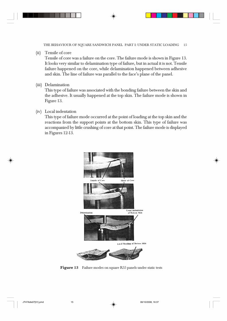
(ii) Tensile of coreTensile of core was a failure on the core. The failure mode is shown in Figure 13.It looks very similar to delamination type of failure, but in actual it is not. Tensilefailure happened on the core, while delamination happened between adhesiveand skin. The line of failure was parallel to the face’s plane of the panel.
(iii) DelaminationThis type of failure was associated with the bonding failure between the skin andthe adhesive. It usually happened at the top skin. The failure mode is shown inFigure 13.
(iv) Local indentationThis type of failure mode occurred at the point of loading at the top skin and thereactions from the support points at the bottom skin. This type of failure wasaccompanied by little crushing of core at that point. The failure mode is displayedin Figures 12-13.
Figure 13 Failure modes on square R55 panels under static tests
JT47Adis07[01].pmd 06/10/2008, 16:3715
AMRAN, NOR AZLAN & MOHD RADZAI16
(v) Local bending of bottom skinThis type of failure occurred around the reaction points at the bottom skin. Thebending line usually was associated with the line of shear of core. The failuremode is shown in Figure 13.
(vi) Folding of panelThis type of failure was the last type of failure in square specimen. The panelstarted to fold and finally tended to form a ‘V’ shape canal. The failure mode isdisplayed in Figure 12.
5.0 DISCUSSION
5.1 Static Tests on Square Specimens
(i) Behaviour of single and double skins platesThe behaviours of single and double skins were quite similar to each other.As the indenter moved downward, the applied loads increased almost linearlyand then started to stay at almost constant values until the end of the tests (seeFigure 6). The maximum loads for the single and double skins were about0.2 and 0.4 kN, respectively. One obvious failure mode that happened to theskin panels was the folding of the panels to form a ‘V’ canal shape (see Figure 7).
(ii) Behaviour of sandwich panels with PU foam under hemispherical and flatindentersThe load-displacement profiles of these panels were quite similar to that ofmonolithic plate. The applied load increased as the indenter moved downward.Shear of core occurred at some point before the maximum load values werereached (see Figures 8 and 9). It occurred at load of 2.2 kN for both panels underhemispherical and flat indenters, while the respective top skin displacementswere 21 and 17 mm. After the shear of core failure occurred, the applied loadincreased until a maximum value was reached. That was the point where the‘folding’ of the panels started. The folding process continued until the testswere stop with a decrease in skin’s rolling direction, which resulted in a slightlydifferent strength value. The load at the starting of the folding process was about2.5 kN under hemispherical indenter and at about 2.4 kN under flat indenter.The displacement of the top skin under both indenter was quite the same at30 mm.
(iii) Behaviour of sandwich panels with R55 core under hemispherical and flatindentersThe failure mode of R55 panel under hemispherical indenter started with localindentation at the reaction point at the bottom skin. This type of failure was
JT47Adis07[01].pmd 06/10/2008, 16:3716
THE BEHAVIOUR OF SQUARE SANDWICH PANEL PART I: UNDER STATIC LOADING 17
accompanied with the crushing of the core around the local indentationpoints. This failure was observed before the maximum point was reached (seeFigure 10). Later, shear of core failure occurred at the maximum load with asudden decrease in the load. This shear of core failure was always be succeededby the tensile of core failure of delamination of skins and local bending ofthe bottom skin. Shear of core occurred at load of 9.5 kN and top skindisplacement of 19 mm under flat indenter. The position of the local bending ofthe bottom skin was always associated with the shear of core’s line. That happenedbecause as shear occurred, there was less resistance to further deformation atthat line.
5.2 Effect of Foam’s Type on Sandwich Panels Performance
The higher density foam (R55) had a higher maximum load than that of the lowerdensity foam (PU). The failure loads were also higher in R55 panels in all types of thecommon failure between the two foams panels. These behaviours were shown in boththe circular and square panels under both hemispherical and flat indenters. Theexplanation was that, R55 panels had a higher modulus of rigidity (EI ). Theexperimental value of compressive Youngs’ modulus, Ec for R55 was 32.5 MPa whilefor PU, Ec = 3.08 MPa.
5.3 Effect of Type of Indenter
Tests under flat indenters had less value of maximum load than that of hemisphericalindenters. The displacement at the respective maximum load was also less with theflat indenter. This was shown in all of the cases. This might be due to the effective areaof contact during the tests. Flat indenter had a higher effective area of contact than thatarea and gave a lower effective load to get the same failure modes.
6.0 CONCLUSION
The behaviour of the sandwich panels under static loadings depends on the propertyof the core materials. The R55 permits more localized failure with higher energy whilethe failures on PU are spread out with less energy required. The common failuremodes on square panels sandwich panel are local indentation, shear and tensile ofcores, delamination of top or bottom skins, local bending of bottom skin and foldingof panels. In the static test, panels with R55 core showed a better performance comparedwith panels with PU core. The use of polyester resin for bonding of the core and theskins was quite satisfactory. The test results can be used to determine behaviours inmaterial models especially through using FEA packages.
JT47Adis07[01].pmd 06/10/2008, 16:3717
AMRAN, NOR AZLAN & MOHD RADZAI18
ACKNOWLEDGEMENTS
The authors would like to thank Department of Mechanical Engineering at Universityof Manchester, Institute of Science and Technology (UMIST) for the laboratory facilitiesand Universiti Teknologi Malaysia (UTM) for the scholarship.
REFERENCES[1] Onat, E. T. and R. M. Haythornthwaite. 1956. The Load Carrying Capacity of Circular Plates at Large
Deflection. Journal of Applied Mechanics. 23: 49-55.[2] Prager, W. 1959. An Introduction to Plasticity. UK: Addison-Wesley Inc.[3] Hodge, P. G. 1959. Plastic Analysis of Structure. McGraw-Hill Book Co., USA.[4] Timoshenko, K. 1970. Theory of Plates and Shells. Oxford, UK: Pregamon Press.[5] Hopkins, H. G. and W. Prager. 1953. The Load Carrying Capacities of Circular Plates. J. Mech. Phys. Solids
2, 1-18.[6] Hopkins, H. G. 1957. Some Remarks Concerning The Dependence of The Solution of Plastic Plate Problem
upon the Yield Criterion, 9th Int. Congress for Appl. Mechanics, Brussels. 448-457.[7] Calladine, C. R. 1969. Simple Ideas in The Large-Deflection Plastic Theory of Plates and Slab. Reprinted
from Engineering Plasticity, edited by Heyman and Leckie, Cambridge, UK : Cambridge University Press.[8] Williams, D., D. Leggett, and H. Hopkins. 1941. Flat Sandwich Panel Under Compressive Loading, A.R.C.:
R&M[9] Allen, H. G. 1969. Analysis and Design of Structural Sandwich Panels. Oxford, UK: Pergamon Press.[10] Gough, E. and De Bruyne. 1940. Wrinkling of a Thin Sheet by a Continuous Supporting Medium. J. Royal
Aero. Soc. 44: 12-43.[11] Hoff, N. J. and S. E. Mautner. 1945. Buckling of Sandwich Type Panels. J. Aero. Sci 12: 285-297.[12] Wan, C. C. 1947. Face Buckling and Core Strength Requirement in Sandwich Construction. J. Aero. Sci. 14:
531-539.[13] Ashby, M. F. and L. J. Gibson. 1997. Cellular Solids-Structure and Properties. Oxford, UK: Pergamon Press.[14] Swanson, S. R. and J. Kim. 2003. Design of Sandwich Structure under Contact Loading. Composite Structures
59: 403-413.[15] Mines, R. A. W. and A. Alias. 2002. Numerical Simulation of The Progressive Collapse of Polymer
Composite Sandwich Beam under Static Loading. Composites: Part A 33: 11-26.[16] Triantafillou, T. C. and L. J. Gibson. 1987. Failure Mode Maps for Foam Core Sandwich Beams. Materials
Science and Engineering 95: 37-53.[17] Mines, R.A.W., A. Alias, Q. M. Li, R. S. Birch and J. A. Close. 1998. On The Measurement of The Crush
Behaviour of Structural Foams. 11th Int. Conference on Experimental Mech. Oxford, 287-292.[18] Li, Q. M., R. A. W. Mines, and R. S. Birch. 2000. The Crush Behaviour of Rochacell-51 WF Structural
Foam. Int. Journal of Solids and Structures 37: 6321-6341.[19] Alias, A. and R. A. W. Mines. 1998. Experimental Results and Techniques on The Crush Behaviour of
Structural Foams. 3rd Int. Symposium on Impact Engineering, Singapore, 379-384.[20] Hong, C. S. and H. Y. Jeong. 1985. Stress Intensity Factor in Anisotropic Sandwich Plate with Part Through
Crack under Mixed Mode Deformation. Eng. Frac. Mech. 21: 285-292.[21] Sayight, A. A. M. 1966. Sandwich Beams and Panels under Bending and Buckling Loads. Ph.D. Thesis.
University of London.[22] Platema, F. J. 1966. Sandwich Construction. UK: John Wiley and Sons Inc.
JT47Adis07[01].pmd 06/10/2008, 16:3718