Embed Size (px)
Citation preview
Bulletin of the Transilvania University of Braşov Series I: Engineering Sciences • Vol. 7 (56) No. 1 - 2014
THE BEHAVIOUR OF SDOF BASE
ISOLATED STRUCTURES
Marius BOTIŞ1
Abstract: The following article’s purpose is studying the behaviour of base isolated structures. In order to estimate that a SDOF (Single Degree of Freedom) base isolated structure will be analysed. The analysis of the structure will be done using numerical analysis methods. Besides the results provided by the analysis of the structure this article can serve as an important collection of the design provisions for base isolated structures presented in the Romanian and European Building Codes for earthquake resistance. Key words: earthquake, base isolation, spectral period, base shear force, aseismic design.
1 Civil Engineering Dept., Transilvania University of Braşov.
1. Introduction The increase in number of major
earthquakes all over the world urge the engineering society on finding new and effective ways in order to fight against the catastrophic results caused by them.
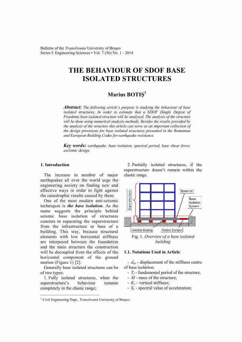
One of the most modern anti-seismic techniques is the base isolation. As the name suggests the principle behind seismic base isolation of structures consists in separating the superstructure from the infrastructure or base of a building. This way, because structural elements with low horizontal stiffness are interposed between the foundation and the main structure the construction will be decoupled from the effects of the horizontal component of the ground motion (Figure 1) [2].
Generally base isolated structures can be of two types:
1. Fully isolated structures, when the superstructure’s behaviour remains completely in the elastic range;
2. Partially isolated structures, if the superstructure doesn’t remain within the elastic range.
Fig. 1. Overview of a base isolated
building 1.1. Notations Used in Article
- dde - displacement of the stiffness centre
of base isolation; - Tf - fundamental period of the structure; - M - mass of the structure; - Kv - vertical stiffness; - Se - spectral value of acceleration;
Bulletin of the Transilvania University of Braşov • Series I • Vol. 7 (56) No. 1 - 2014 56
- fj - seismic force for each level of super-structure;
- mj - mass for each level of super-structure;
- xi - amplification factor in x direction; - etot,y - eccentricity between center of
mass and center stiffness; - Kxi, Kyi - stiffness of each isolator in x
and y direction; - xi and yi - distances from the center of
gravity of all isolators until each isolator. 2. Provisions of the Romanian Seismic
Code (P100-1/2013) for Base Isolated Structures
Section 11 of the aforementioned building
code governs the utilisation of base isolation in Romania. It has the same content as Section 10 of the European Seismic Code for Buildings SR EN 1998-1:2006.
2.1. Fundamental Requirements for Base
Isolated Structures [3-5] Isolating devices are required to be
designed with an increased reliability. This shall be effected by applying a magnification factor (γs) to the seismic action applied on each isolating unit. The recommended value is γs = 1.2.
2.2. Compliance Criteria [3-5]
In order to conform to all the
fundamental requirements of P100-1 the following criteria should be respected in all the limit states of the structure:
1. At the damage limitation state, all lifelines crossing the joints around the isolated structure shall remain within the elastic range.
2. For the aforementioned limitation state the inter-story drifts of the super-structure should not exceed those recommended in Section 4 of P100-1/2013. The same applies for the infra-structure too.
3. At the Ultimate limit state, the isolating devices may attain their ultimate capacity, while the superstructure and substructure remain in their elastic range. Then there is no need for capacity design and ductility detailing in either the superstructure or the infrastructure.
4. At the Ultimate limit state, gas lines and hazardous lifelines crossing the joints separating the superstructure from the surrounding ground or construction shall be designed to accommodate safely the relative displacement between the isolated superstructure and the surrounding ground or constructions, taking in account the magnification factor (γs) recommended in Chapter 2.1 of the present article.
5. The provisions presented in Section 11 of P100-1/2013 shall be used only in the case of isolated structures.
6. Although in some cases a partially inelastic behaviour of the substructure could be accepted, the Seismic Code considers the infrastructure acting exclusively in the elastic range.
2.3. General Design Provisions [3-5]
2.3.1. General provisions concerning the
devices [3-5] Sufficient space between the super-
structure and the substructure shall be provided, together with other necessary arrangements, to allow inspections, replacement of the devices during the lifetime of the construction.
If necessary, the isolating devices should be protected against the effects of potential hazardous events, such as fire, chemical or biological attack.
2.3.2. Control of undesirable movements
[3-5] To minimize the torsional effects, the centre
of effective stiffness and centre of damping
Botiş, M.: The Behaviour of SDOF Base Isolated Structures 57
of the structure should be positioned as close as possible to the projected centre of mass on the isolation surface.
In order to reduce the different compartment of the isolating devices, the compressive stress induced in them by the permanent actions (dead and super dead loads) should be as uniform as possible.
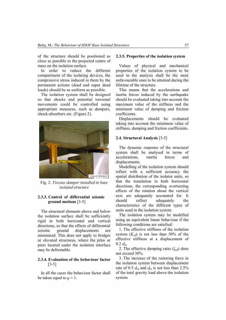
The isolation system shall be designed so that shocks and potential torsional movements could be controlled using appropriate measures, such as dampers, shock-absorbers etc. (Figure 2).
Fig. 2. Viscous damper installed in base
isolated structure
2.3.3. Control of differential seismic ground motions [3-5]
The structural elements above and below
the isolation surface shall be sufficiently rigid in both horizontal and vertical directions, so that the effects of differential seismic ground displacements are minimised. This does not apply to bridges or elevated structures, where the piles or piers located under the isolation interface may be deformable.
2.3.4. Evaluation of the behaviour factor
[3-5] In all the cases the behaviour factor shall
be taken equal to q = 1.
2.3.5. Properties of the isolation system Values of physical and mechanical
properties of the isolation system to be used in the analysis shall be the most unfavourable ones to be attained during the lifetime of the structure.
This means that the accelerations and inertia forces induced by the earthquake should be evaluated taking into account the maximum value of the stiffness and the minimum value of damping and friction coefficients.
Displacements should be evaluated taking into account the minimum value of stiffness, damping and friction coefficients.
2.4. Structural Analysis [3-5]
The dynamic response of the structural
system shall be analysed in terms of accelerations, inertia forces and displacements.
Modelling of the isolation system should reflect with a sufficient accuracy the spatial distribution of the isolator units, so that the translation in both horizontal directions, the corresponding overturning effects of the rotation about the vertical axis are adequately accounted for. It should reflect adequately the characteristics of the different types of units used in the isolation system.
The isolation system may be modelled using an equivalent linear behaviour if the following conditions are satisfied:
1. The effective stiffness of the isolation system (Keff) is not less than 50% of the effective stiffness at a displacement of 0.2 dde.
2. The effective damping ratio (ξeff) does not exceed 30%.
3. The increase of the restoring force in the isolation system between displacement rate of 0.5 dde and dde is not less than 2.5% of the total gravity load above the isolation system.
Bulletin of the Transilvania University of Braşov • Series I • Vol. 7 (56) No. 1 - 2014 58
If a linear equivalent model is used in the design process, the effective stiffness of each isolator unit (i.e. the secant value of the stiffness at the total design displacement ddb) should be used. The effective stiffness (Keff) of the isolation system is the sum of the effective stiffnesses of the isolator units.
.1
n
iieff KK (1)
If an equivalent linear model is used, the
energy dissipation of the system should be expressed in terms of equivalent viscous damping, as the “effective damping of the system” (ξeff).
When the values of the effective stiffness or the effective damping are defined in relation with the displacement of the system (dde), an iterative procedure shall be used in order to determine the actual displacement, until the difference between the assumed and calculated value of dde is less than 5% of the assumed value.
2.4.1. Simplified linear analysis [3-5]
The simplified linear analysis method
may be applied to isolation systems with equivalent linear damped behaviour, if they also conform to all of the following conditions:
1. The largest dimension of the super-structure in plan does not exceed 50 m.
2. The infrastructure is sufficiently rigid to minimize the effects of differential displacements of the ground.
3. The effective period (Teff) complies to the following condition:
.s33 efff TT (2)
4. The lateral-load resisting system of the
superstructure should be regularly and symmetrically arranged along the two main axes of the structure in plan.
5. The rocking rotation at the base of the substructure should be negligible.
6. The ratio between the vertical (Kv) and horizontal (Keff) stiffness of the isolation system should comply to:
.150eff
v
KK (3)
7. The fundamental period in the vertical
direction should not be longer than 0.1 s.
.s1.02 v
v KMT (4)
The simplified linear analysis method
considers two horizontal dynamic translations and superimposes static torsional effects. It assumes that the superstructure has a rigid-body movement if all the aforementioned conditions are satisfied.
The torsional movement around the vertical axis can be neglected in the evaluation of the effective horizontal stiffness and in the simplified linear analysis,if in each of the two principal horizontal directions, the total eccentricity (including the accidental eccentricity) between the stiffness centre of the isolation system and the vertical projection of the centre of mass of the superstructure does not exceed 7.5% of the length of the superstructure transverse to the horizontal direction considered. This is a crucial condition for the applicability of the simplified linear analysis method. The effective period for the translation
could be found using:
.2eff
eff KMT (5)
where, Keff is defined by Eq. (1). The displacement of the stiffness
centre due to the seismic action should be
Botiş, M.: The Behaviour of SDOF Base Isolated Structures 59
calculated in each horizontal direction, from the following expression:
.)(
min,
,
eff
effeffede K
TSMd
(6)
The horizontal forces applied at each
level of the superstructure should be calculated, in each horizontal direction through the following expression:
).( , effeffejj TSmf (7)
If the torsional movement about the
vertical axis could be neglected, the torsional effects in the individual isolator units may be accounted for by amplifying, in each direction, the values calculated for dde and fj with factor di given (for the action in the x direction) by:
.1 2
,i
y
ytotxi y
re
(8)
where 2
yr is the torsional radius of the isolation system in the y direction, as given by:
.)(
1
1
22
2
n
ixi
n
ixiiyii
y
K
KyKxr (9)
3. Linear Simplified Analysis Model of a
SDOF (Single Degree of Freedom) Base Isolated Structure
The simplest possible dynamical model
of a base isolated structure is that which has only 1 DOF. Although, because in the case of base isolated structures the main effect of the seismic action on the structure is consumed in the fundamental period [3], such a model can provide precious results regarding the behaviour and/or stress state of the structure.
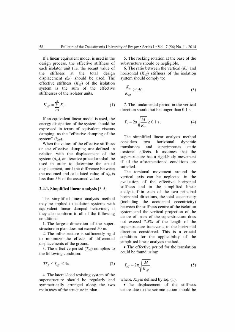
For analysis purposes let’s consider the SDOF structure presented in Figure 3.
Fig. 3. SDOF base isolated structure
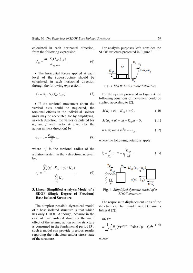
For the system presented in Figure 4 the
following equations of movement could be applied according to [2]:
0 uKucuM effs , (10)
0)( uKucuuM effg , (11)
guuuu 22 , (12)
where the following notations apply:
MK
cc eff
cr ; . (13)
Fig. 4. Simplified dynamic model of a
SDOF structure The response in displacement units of the
structure can be found using Duhamel’s Integral [2]:
.)(sin)(1)(
*0
)(*
dteu
tut t
g (14)
where:
Bulletin of the Transilvania University of Braşov • Series I • Vol. 7 (56) No. 1 - 2014 60
.1 2* (15) As the damping ratio in civil structures is
negligible, it could be assumed that:
.* The maximum value of the relative
displacement of the structure is defined by the following expression [2]:
,),(
)()( max
effeffd TS
tutu
(16)
where Teff is defined by Eq. (5).
The dynamic response of the SDOF system can be computed either in displacement, velocity or acceleration units using the relations below [1]: The spectral values of displacements
are defined by:
.)(sin)(
),(
max0 *
)(
tt
g
effeffd
dteu
TS
(17)
The spectral value of velocity can be
found using:
.)(sin)(
),(
max0)(
t tg
effeffv
dteu
TS
(18)
The spectral value of acceleration can
be accounted for using:
.)(sin)(
),(
max0)(
t tg
effeffa
dteu
TS
(19)
The base shear of the structure can be
defined using Eq. (20-22) [2], [3]:
).,(
),(
effeffa
effeffdT
TSM
TSKF
(20)
4. Performance Analysis of a SDOF Base
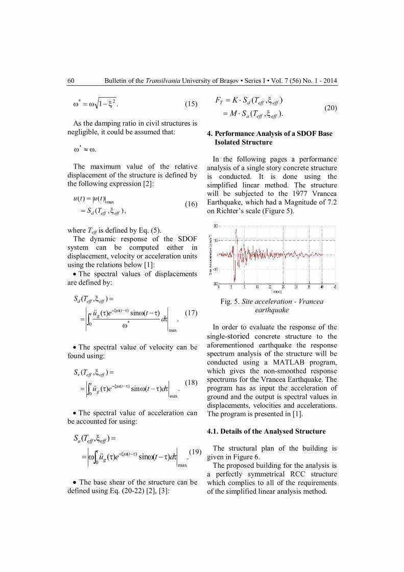
Isolated Structure In the following pages a performance
analysis of a single story concrete structure is conducted. It is done using the simplified linear method. The structure will be subjected to the 1977 Vrancea Earthquake, which had a Magnitude of 7.2 on Richter’s scale (Figure 5).
Fig. 5. Site acceleration - Vrancea
earthquake In order to evaluate the response of the
single-storied concrete structure to the aforementioned earthquake the response spectrum analysis of the structure will be conducted using a MATLAB program, which gives the non-smoothed response spectrums for the Vrancea Earthquake. The program has as input the acceleration of ground and the output is spectral values in displacements, velocities and accelerations. The program is presented in [1].
4.1. Details of the Analysed Structure
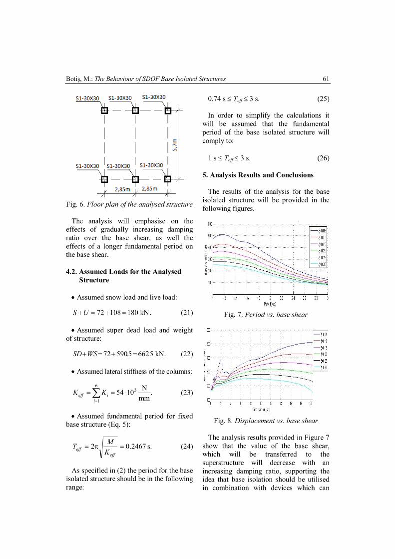
The structural plan of the building is
given in Figure 6. The proposed building for the analysis is
a perfectly symmetrical RCC structure which complies to all of the requirements of the simplified linear analysis method.
Botiş, M.: The Behaviour of SDOF Base Isolated Structures 61
Fig. 6. Floor plan of the analysed structure
The analysis will emphasise on the
effects of gradually increasing damping ratio over the base shear, as well the effects of a longer fundamental period on the base shear.
4.2. Assumed Loads for the Analysed
Structure Assumed snow load and live load:
.kN18010872 US (21) Assumed super dead load and weight
of structure:
.kN5.6625.59072 WSSD (22) Assumed lateral stiffness of the columns:
.mmN1054
6
1
3
i
ieff KK (23)
Assumed fundamental period for fixed
base structure (Eq. 5):
2467.02 eff
eff KMT s. (24)
As specified in (2) the period for the base
isolated structure should be in the following range:
0.74 s Teff 3 s. (25) In order to simplify the calculations it
will be assumed that the fundamental period of the base isolated structure will comply to:
1 s Teff 3 s. (26)
5. Analysis Results and Conclusions The results of the analysis for the base
isolated structure will be provided in the following figures.
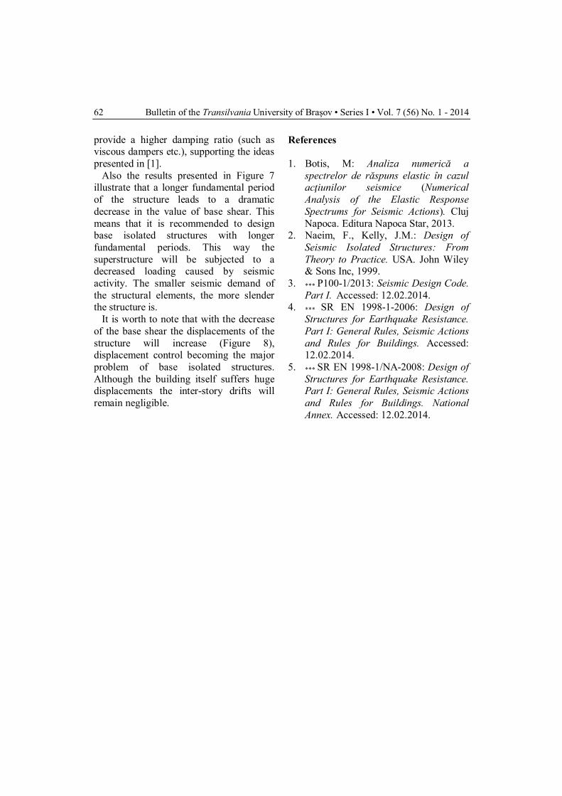
Fig. 7. Period vs. base shear
Fig. 8. Displacement vs. base shear
The analysis results provided in Figure 7
show that the value of the base shear, which will be transferred to the superstructure will decrease with an increasing damping ratio, supporting the idea that base isolation should be utilised in combination with devices which can
Bulletin of the Transilvania University of Braşov • Series I • Vol. 7 (56) No. 1 - 2014 62
provide a higher damping ratio (such as viscous dampers etc.), supporting the ideas presented in [1].
Also the results presented in Figure 7 illustrate that a longer fundamental period of the structure leads to a dramatic decrease in the value of base shear. This means that it is recommended to design base isolated structures with longer fundamental periods. This way the superstructure will be subjected to a decreased loading caused by seismic activity. The smaller seismic demand of the structural elements, the more slender the structure is.
It is worth to note that with the decrease of the base shear the displacements of the structure will increase (Figure 8), displacement control becoming the major problem of base isolated structures. Although the building itself suffers huge displacements the inter-story drifts will remain negligible.
References
1. Botis, M: Analiza numerică a spectrelor de răspuns elastic în cazul acţiunilor seismice (Numerical Analysis of the Elastic Response Spectrums for Seismic Actions). Cluj Napoca. Editura Napoca Star, 2013.
2. Naeim, F., Kelly, J.M.: Design of Seismic Isolated Structures: From Theory to Practice. USA. John Wiley & Sons Inc, 1999.
3. *** P100-1/2013: Seismic Design Code. Part I. Accessed: 12.02.2014.
4. *** SR EN 1998-1-2006: Design of Structures for Earthquake Resistance. Part I: General Rules, Seismic Actions and Rules for Buildings. Accessed: 12.02.2014.
5. *** SR EN 1998-1/NA-2008: Design of Structures for Earthquake Resistance. Part I: General Rules, Seismic Actions and Rules for Buildings. National Annex. Accessed: 12.02.2014.