Embed Size (px)
Citation preview

Ali Asghar
Pakistan Atomic Energy Commission
IAEA Technical Meeting on Integrated Approaches to the Back End of the Fuel Cycle Headquarters Vienna Austria, 17–19 July 2018
The Back End: Spent Nuclear Fuel Management in Pakistan

Outline
• PAEC Nuclear Power Program
• Overview of Strategy for SFM in Pakistan
• Back End Policy and Strategy
• Interfaces Issues in SFM
• Stakeholders Responsibilities
• CHASHNUPP, Spent Fuel Management
• KANUPP, Spent Fuel Management
• Conclusion 2
CHASNUPP KANUPP
C-1 C-2 C-3 C-4 K-1 K-2/K-3
Commercial
Operation2000 2011 2016 2017 1972 2021
Rated Thermal
Power MWth998.6 998.6 998.6 998.6 432.8
Gross Electric
Power MWe325 330 340 340 137
1100 MW
each
Reactor Type PWR PWR PWR PWR PHWR PWR
Origin China China China China Canada China
3
Pakistan’s Nuclear Power Program

• To have significant portion of nuclear energy in the overall
energy mix. It is central element of Pakistan's energy policy.
• Following strategies are adopted for SFM:
– Enhancement in Capacity of Wet Storage Pools.
– Facility Development of Spent Fuel Dry Storage.
– Site Selection for Ultimate Disposal Facility
– Hold and See Strategy.
4
Overview of Strategy for SFM in Pakistan

5
SNF from Reactor Core
On-site Wet Storage On-site Dry Storage
Closed cycleDeep Geological
Repository
Back End Policy and Strategy
Policy? Policy?

• Issues in implementing of re-racking strategy in wet
storage to enhance the storage capacity beyond design.
• Need to develop improved strategy for Integration of Wet
SNF storage & Dry storage at Reactor Site
• Design & Manufacturing of transportation & storage Casks
• Licensing interface among PNRA,PAEC and IAEA for dry
storage facility and Casks
6
Interfaces Issues in SFM

Responsibilities of Operators (PAEC)
• In Pakistan, PAEC, the main operator, is responsible for
Safe Management of Spent Fuel
• As per policy, a Central Radioactive Waste Management
Fund is maintained by PAEC.
• SNF is currently stored (Wet) at the reactor sites in pools.
• Longer-term dry storage at each site is proposed and
work is in progress. 7
Responsibilities of Stakeholders for Spent Fuel Management

Responsibilities of Regulator (PNRA) :
• Responsible for development of requirements and
procedures for the licensing of various types of
radioactive waste management facilities.
• Responsible to advise and inform on technical matters
and on the effect of polices with respect to assuring the
safety of the public and the environment.
8
Responsibilities of Stakeholders for Spent Fuel Management
Responsibilities of Directorate General National
Repository (DGNR)
• Responsible for Disposal Activities: Off site
transportation, Siting and development of disposal
facilities
9
Responsibilities of Stakeholders for Spent Fuel Management

10
Main NPPs sites
CHASNUPPWet Interim Storage
(in-operation)
Dry Interim Storage(under construction)
KANUPPWet Interim Storage
(in-operation)
Dry Interim Storage(under construction)

11
CHASHNUPP(C-1 to C-4)

Plant Storage capacity
Occupied Remaining space
Adequacy(year)
C1 721 FA* 440FA 321FA 2021
C2 721 FA 200FA 521FA 2030
C3 721 FA 40FA 681FA -
C4 721 FA - 721FA -
Storage capacity: SNF generated from15 RFOs (600 FA)+ 1 full core (121 FA)=721
*FA: Fuel Assembly
12
Spent Nuclear Fuel (SNF) Storage at Reactor Pools by JUNE, 2018
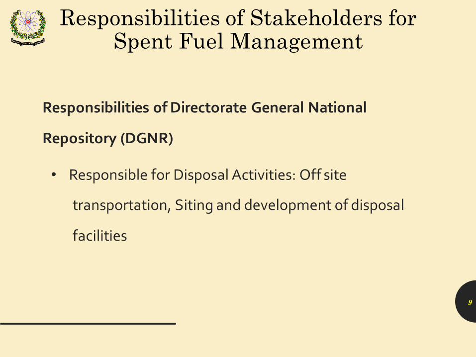
• Overall length, mm:
– 3500
• Overall transverse dimensions, mm:
– 199.3 × 199.3
• Mass of assembly, kg:
– 462.54
13
Fuel Assembly Characteristics

STORAGE POOL 2
Cask Loading Pool4x4
Cask Cleaning Pit
4x4
Cask Handling Opening 5.4x3
TRANFER
CANAL
STORAGE POOL 1
14
Lay Out of Fuel Building Wet Storage

15
75t
12.150
Pool Crane 2/5t
13.300
1.7501.500
8.000
±0.000
5.150
10.500
16.800
22.400
25.000
20.000
SPENT FUEL STORAGE POOLCaskLoadingPool
CaskCleaningPit
4.8
Spent Fuel Building
15
16
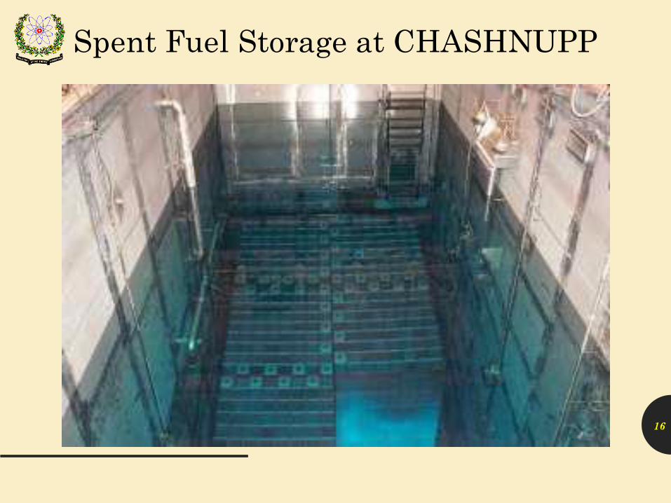
Spent Fuel Storage at CHASHNUPP

• PAEC has planned to establish Dry Storage facility which
will serve as interim storage for spent fuel till availability
of National Repository (Hold-n-See).
• Location: within plant boundaries
17
Long Term Strategy for SNF Storage (Dry Storage)
• Scheme:
– Canister (including basket)
– One Metallic Cask (Transfer Cask)
– Single purpose Concrete Casks (dry storage)
– Storage building with hot cell
• The dry cask storage system will provide confinement,
radiation shielding, structural integrity, criticality control and
heat removal for SNF. 18
Dry Storage Scheme (Proposed)

▪ Due to harsh environmental conditions and security issues
indoor storage of dry casks on concrete floor is selected.
▪ Three buildings with passive ventilation features will be
constructed.
▪ The storage capacity of three buildings will be sufficient
enough to store SNF generated from 60 years operation
of C1 ~ C4.
19
Dry Casks Storage Buildings
• For Site Specific license of dry storage facility CNPGS will follow
US NRC 10CFR 72
• For licensing process, PNRA regulation “Regulations for Licensing
of Nuclear Installations in Pakistan, PAK/909 (Rev.1)” will be
followed
• Letter of intent and information regarding license applicant
forwarded to PNRA
• PAEC, Disarmament & Safeguard directorate has forwarded the
CNPGS intent to IAEA for provision of safeguards measures 20
Licensing Issues

21
KANUPP
• The KANUPP SFB is divided into four areas.
– Storage area
– Inspection area
– Shipping cask area
– Decontamination area
• Designed for 20 years of operation with 80% capacity factor
22
KANUPP Spent Fuel Bay
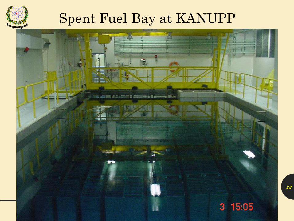
23
Spent Fuel Bay at KANUPP

• 11 spent fuel bundles stored in one storage tray
• Storage Layout : 120 stacks of trays each consisting of 18 tiers
of trays
• Design Storage capacity: 23,760 spent fuel bundles
• Total Water Depth : 5.94 m
• Water Shield thickness: 3.96 m
• 8.7E-3 mSv/hr is maintained at 30.5 cm (1 foot) above the
water surface 24
KANUPP Spent Fuel Bay (SFB)

• Almost complete its design capacity
• An alternate short term remedy is to enhance the storage
capacity of existing SFB
• A dry storage facility is being planned as an ultimate
solution of storage problem
25
Storage Problem in SFB of KANUPP
• Increase in no. of layers / stack.
• Place cooler bundle tray at top of stack.
• Reserve space for storage of in-core fuel bundles in
emergency conditions.
26
Enhancement in Storage Capacity

• Computation of thickness of water column for shielding
• Analysis of cooling capacity of bay water
• Criticality assessment (requirement of the regulator)
• Seismic Analysis
27
Addressing Issues for Enhancing Wet Storage Capacity

– Contribution of all spent fuel bundles stored in storage bay is
modeled
– The rate of decrease of activity & decay heat of spent fuel is
very fast within 10 years of cooling time; slows down after
wards
– 10 years cooling period is considered in the shielding
Calculations
28
Water Shielding Thickness Calculation - Assumptions
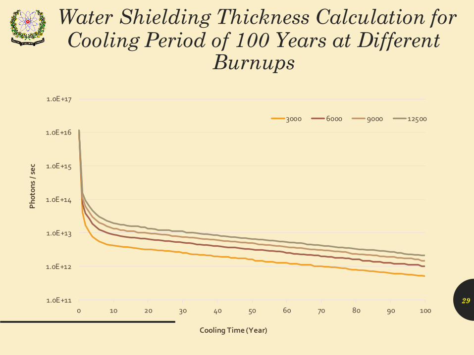
Water Shielding Thickness Calculation for Cooling Period of 100 Years at Different
Burnups
1.0E+11
1.0E+12
1.0E+13
1.0E+14
1.0E+15
1.0E+16
1.0E+17
0 10 20 30 40 50 60 70 80 90 100
Ph
oto
ns
/ se
c
Cooling Time (Year)
3000 6000 9000 12500
29
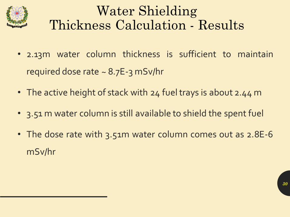
• 2.13m water column thickness is sufficient to maintain
required dose rate ~ 8.7E-3 mSv/hr
• The active height of stack with 24 fuel trays is about 2.44 m
• 3.51 m water column is still available to shield the spent fuel
• The dose rate with 3.51m water column comes out as 2.8E-6
mSv/hr
30
Water Shielding Thickness Calculation - Results

Dose rates due to 10 years, 5 years and 1 year cooled spent fuel
bundles are tabulated as:
Dose Rates (mSv/hr) w.r.t. various cooling periods at available shield thickness
Cooling Period (Years)
Dose Rates (mSv/hr)
Available Water Shield Thickness (m)
At 3.51 m At 3.20 m
10 2.78E-06 4.35E-06
5 6.09E-05 7.22E-05
1 1.22E-03 1.48E-0331
Dose Rates

• Design total heat removal capacity of bay cooling system is
1.8 MWth
• 0.21 MWth decay heat will be generated in the spent fuel
storage bay due to overall 31680 spent fuel
• 0.27 MWth decay heat is calculated due to unloading of in-
core fuel bundles (assuming 3 months cooling)
• The calculated total decay heat 0.48 MWth is well in limits
of design heat removal capacity of bay cooling system 32
Analysis of Bay Cooling Capacity

• The spent fuel placed in HDTR in proposed layout in the
spent fuel storage bay will remain subcritical in operational
and accidental conditions
• Use of steel in spent fuel trays, racks and liner in the
surrounding walls of the bay make Keff even lesser
33
Criticality Assessment
• A seismic analysis enabled to assess the stability against
seismic event (ground acceleration 0.2g)
• The result of analysis reveals that overturning will not take
place under the specified seismic loading
• Sliding will take place, however much less than the
clearance available b/w two adjacent racks or between a
rack and bay wall
• Stress analysis ensured that the axial, bending and shear
stresses are within the allowable limits34
Seismic Analysis
• Storage capacity of SFB enhanced by increasing tray stack
height from 18 layers to 24
• Seismic stability will be attained by placing these trays in a
“High Density Tray Rack”
– Two columns each consisting of 24 layers of trays will be loaded into
one rack
– 60 racks could be arranged in layout of 10 x 6 in the storage area of
SFB35
Improved Proposed Storage Pattern

• The high density tray rack is a seismically and structurally
qualified stainless steel
frame to be placed in storage
area of spent fuel storage bay.
36
Storage Capacity has been enhanced by 33.3%.
High Density Tray Rack

• Each rack will hold 528 spent fuel bundles
• 7920 more spent fuel can be stored
• Overall 31680 spent fuel can be accommodated
• The development and implementation of HDTR System at
KANUPP will enhance 1/3rd of design storage capacity
37
Proposed Amendment in Existing Storage Pattern
• High Density Spent Fuel (HDSF) racks are now successfully
designed, developed and manufactured.
• Total 06 racks are already lowered in the SFSB and additional 02
racks will be lowered in near future and this will provide storage
capacity for about one year.
• It is now planned to develop minimum 10 racks per year so that
maximum 60 will be completed that will be sufficient for plant
operation up to year 2019.
• SFSB capacity would be enhanced from 23,760 to 31,680
bundles after the installation of HDSF racks. 38
Proposed Amendment in Existing Storage Pattern

39
High Density Tray Rack (Loaded)

Parameters Existing StorageEnhanced Storage
(HDTR System)
Single Storage Unit in Bay 18 Fuel Trays Stack 48 Fuel Trays Rack
(2 x 24 trays)
Number of Bundles in Single Unit 198 (11 x 18)528 (11 x 48)
Array in Bay 12x10 10x6
Number of Bundles in Bay 23760 (12 x 10 x 198) 31680 (10 x 6 x 528)
Fuel Storage Advantage (%) - 33.3
Available Water Shielding (cm) 396 351
40
Comparison b/w Existing and Enhanced Storage Scheme
41
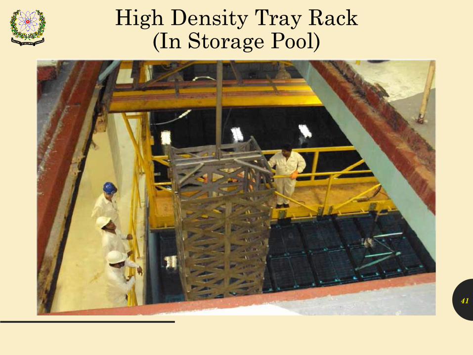
High Density Tray Rack (In Storage Pool)

▪ Pakistan is committed to operate NPPs in safe & secure manner to fulfill the energy needs under IAEA assistance & safeguards
▪ Pakistan gives importance to back end activities of Nuclear Fuel Cycle
• Currently, following steps are taken in SNF Management atCHASHNUPP and KANUPP :– Enhancement in Capacity of Wet Storage Pools– Facility Development of Spent Fuel Dry Storage– Design and development of casks
▪ Initiation of siting process for Deep Geological Disposal Facility
▪ Wait and see Strategy for SNF 42
Conclusion

Thank you for your
Attention
43