Embed Size (px)
Citation preview
The Assessment of flue gas particulate abatement in wood burning boilers – Phase 2
Report for Forestry Commission Scotland
Restricted Commercial ED56285 Issue Number 3 March 2011
The Assessment of flue Gas Particulate abatement in wood Burning Boilers – Phase 2
AEA in Confidence Ref: AEA/ED56285/Phase 2- Issue Number 3 ii
Customer: Contact:
Forestry Commission Scotland AEA Technology plc Glengarnock Technology Centre Caledonian Road Lochshore Business Park Glengarnock Ayrshire KA14 3DD t: 0870 190 5307 f: 0870 190 5240 e: [email protected] AEA is a business name of AEA Technology plc AEA is certificated to ISO9001 and ISO14001
Customer reference:
Confidentiality, copyright & reproduction:
© Copyright AEA Technology plc
This report is the Copyright of Forestry Commission Scotland and has been prepared by AEA Technology plc under contract to Forestry Commission Scotland dated 29.6.10 The contents of this report may not be reproduced in whole or in part, nor passed to any organisation or person without the specific prior written permission of Forestry Commission Scotland. AEA Technology plc accepts no liability whatsoever to any third party for any loss or damage arising from any interpretation or use of the information contained in this report, or reliance on any views expressed therein.
Author:
Robert Stewart, Alan Leonard, Dr Scott Hamilton, Stephen Fleming
Approved By:
Dr Scott Hamilton
Date:
11th March 2011
Signed:
AEA reference:
Ref: ED56285- Phase 2- Issue Number 3
This report was prepared for Forestry Commission Scotland under the Regional Biomass Advice Network (RBAN) project, in partnership with Scottish Government, Scottish Enterprise and Forestry Research. RBAN is part-funded by the European Regional Development Fund.
The Assessment of flue Gas Particulate abatement in wood Burning Boilers – Phase 2
AEA in Confidence Ref: AEA/ED56285/Phase 2- Issue Number 3 ii
Executive summary
The Forestry Commission commissioned AEA to undertake a review of the current abatement technologies and the measurement methods and procedures available used to assess the performance of abatement equipment used to reduce the emissions of particulate material from the combustion of wood. This report is a summary of work undertaken as Phase 2 of the project focussing on the methods available for particulate emission measurement and for determination of abatement performance. There are a number of International and national sampling standards for the determination of the particulate material concentrations from combustion sources. There are national Standards and a draft International Standard available for assessing performance of filter media but there is not a standard available for the assessment of the efficiency or performance of particulate abatement equipment. However, a ‘Workshop Agreement’ document published by CEN provides a framework for assessing performance of abatement equipment. This review indicates that Standards for quantifying performance of emission abatement equipment are limited. However, if performance is defined in terms of an emission concentration or rate, then emission testing can provide a means to assess compliance with an emission guarantee. An emission performance guarantee from a boiler and/or abatement manufacturer could be helpful to developers and planning authorities by providing more confidence that claimed emission levels (and hence air quality impacts) would be achieved.
There are existing Standards suitable for determining particulate emission concentrations from biomass combustion processes. These are generally well-defined and there are accredited testhouses readily available in the UK to undertake such measurements. Total particulate measurement Standards are generally suitable (or can be adapted comparatively easily) for smaller sizes of duct associated with smaller boilers (in particular duct diameters <0.5 m). There are also Standard and other methods available for determination of PM10 and/or PM2.5 emission concentration however these may require substantial modification to apply at smaller boilers.
There is a general lack of drivers which would encourage abatement system manufacturers to provide performance data in a way that local environmental officers can utilise across the UK in assessing the potential air quality implications of a biomass system. The need for abatement performance data is currently largely driven by specific local concerns, though perhaps there is potential for a national programme of testing/certification similar to that carried out for Clean Air Act exemptions.
An emission monitoring protocol also needs to address operation of the boiler. The availability of testhouses accredited to determine appliance output or efficiency to Standard test methods is limited. There are a number of testhouses in Europe (including at least one in the UK) with laboratory facilities for testing solid fuel boilers (to EN303-5) but very few testhouses appear to offer accredited testing for output and efficiency of installed boilers.
An abatement efficiency protocol could be developed by undertaking particulate measurement Standards upstream and downstream of abatement equipment but while this is a practical mechanism for assessing a particular abatement technology on a particular boiler and fuel it may not provide sufficient control of the inlet conditions to apply as a general type approval method for abatement technology.
Some elements of abatement equipment performance are addressed in Standards. For example, performance testing of filter media. But the Standard assessments are under highly specific, defined conditions to assure comparability of testing and this testing does not
The Assessment of flue Gas Particulate abatement in wood Burning Boilers – Phase 2
AEA in Confidence Ref: AEA/ED56285/Phase 2- Issue Number 3 iii
quantify other aspects of abatement performance. In particular, maintenance interval, consumptions, endurance and, limits of operation are not addressed in current Standards.,
The following Recommendations are made to inform future development of test protocols for biomass boiler abatement equipment :
1. Determine whether common filtration and weighing temperature criteria are required for measurement of particulate from biomass combustion – the particulate measurement Standards currently adopt different temperatures.
2. Development of criteria to determine whether condensable emissions are likely to form a significant component of the particulate emission and hence indicate a need for further emission testing.
3. Development of clear performance guarantees for particulate emission concentrations and rates for boiler and abatement equipment would assist developers and planning officers to determine if an installation represents a risk to local air quality. Such guarantee criteria may not be appropriate where a large number of boilers already exist (or are proposed) in an area but could allow distinction between equipment suitable for use where there is no AQMA, areas which are close to exceeding air quality standards and areas where an AQMA has been declared. Ideally such guarantees should be based on emission concentrations or rates which are unlikely to cause an air quality exceedence.
4. To determine compliance with performance guarantees requires a common test protocol ideally based on Standards to assure consistency of interpretation across different stakeholder groups. Such a test protocol should address emission measurements, fuel and boiler conditions.
5. Development of a test protocol to incorporate testing at low and rated output conditions would allow demonstration of emissions across the operating range of a boiler (low and rated output testing). This would allow manufacturers and suppliers to demonstrate suitability of equipment for planning and other purposes (for example Clean Air Act Exemption).
6. Development of a protocol (based on Standards where available) to determine emission and operational criteria could allow abatement and boiler manufacturers to demonstrate performance of abatement equipment. Performance elements for inclusion in such a protocol would need to be determined but could include : - particulate emission - abatement efficiency (inlet and outlet measurements or filter challenge test) - acceptable or maximum flow range of abatement equipment - maximum temperature of equipment - suitability of materials of construction for biomass boilers - electrical consumption (peak and continuous load) - air consumption - maintenance interval - filter media life (if a consumable)
This list is not exhaustive. As a first stage, stakeholders need to determine which parameters are needed to develop a protocol.
The Assessment of flue Gas Particulate abatement in wood Burning Boilers – Phase 2
AEA in Confidence Ref: AEA/ED56285/Phase 2- Issue Number 3 iv
Table of contents
1 Introduction ................................................................................................................ 1
1.1 Project aims – Phase 2 ...................................................................................... 1
1.2 Report structure ................................................................................................. 1
2 Particulate Emission from Wood Combustion ......................................................... 2
3 Standard Particulate Measurement Methods ........................................................... 5
3.1 Periodic, Integrated and Continuous Methods .................................................... 5
3.2 General principles of integrated measurements ................................................. 5
3.3 European Committee for Standardisation (CEN) ................................................ 7
3.4 International Standards Organisation (ISO) ........................................................ 8
3.5 United Kingdom ................................................................................................. 9
3.6 Germany ............................................................................................................ 9
3.7 United States ....................................................................................................10
3.8 Summary of Standard integrated methods for total particulate, PM10 and PM2.5 12
4 Other Particulate Measurement Techniques ...........................................................14
4.1 US Dilution tunnel research ...............................................................................14
4.2 Tapered element oscillating micro-balance (TEOM) ..........................................15
4.3 Measurements of particle size distributions .......................................................15
5 Supporting Measurements .......................................................................................17
5.1 Overview ...........................................................................................................17
5.2 Emissions .........................................................................................................18
5.3 Boiler load .........................................................................................................18
5.4 Fuel quality........................................................................................................18
5.5 Consumptions and efficiency ............................................................................19
5.6 Abatement technology ......................................................................................19
6 Methodologies for Assessing Particulate Abatement Efficiency ...........................20
6.1 United Kingdom Filter Testing ...........................................................................20
6.2 United States of America ...................................................................................20
6.3 CEN ..................................................................................................................21
6.4 ISO ...................................................................................................................22
6.5 Other .................................................................................................................23
7 Development of a Test Procedure ............................................................................24
7.1 Aims of test procedure ......................................................................................24
7.2 Drivers for development of a test procedure ......................................................24
7.3 Confidence in test results ..................................................................................25
7.4 Testing for air quality impacts ............................................................................25
7.5 Performance tests for abatement plant ..............................................................25
8 Conclusions and Recommendations .......................................................................27
1
1 Introduction
1.1 Project aims – Phase 2
The project aims to investigate the technologies available and coming onto the market which abate particulate emissions from wood-burning boilers.
Phase 2 is intended to outline the available techniques for assessing the performance of particulate abatement techniques applicable to small biomass boiler installations (50 – 2000 kW output).
1.2 Report structure
The report introduces the combustion process and some of the issues associated with particulate emission sampling (Section 2) followed by a description of emission testing Standards for particulate, PM10 and PM2.5 (Section 3).
Other measurement methods for particulate measurements (principally particle size and counting methods) are outlined in Section 4.
Section 5 summarises supporting measurements which should be considered when characterising emissions from small biomass boilers.
The Standards and other methods for assessing abatement plant performance are introduced at Section 6.
Section 7 introduces requirements which should be considered for a test protocol for assessing abatement performance and discusses drivers (or lack of) for manufacturers of abatement equipment t test the performance of their equipment.
Conclusions and recommendations are provided in Section 8.
2
2 Particulate Emission from Wood Combustion
As result of the components present in wood there are a variety of particulates produced. It has been reported1 that the design of the combustion plant can influence both the quantity and type of particle emitted. Boilers that achieve high combustion efficiency result in comparatively lower emissions of unburned hydrocarbons and soot. Particles from well-designed automatically operated wood combustion appliances consist mainly of inorganic matter such as ash and salts, but particles from (for example) batch-fed, natural draught, manually-controlled appliances operated under poor conditions consist mainly of soot and organic substances as a result of their relatively low combustion efficiency.
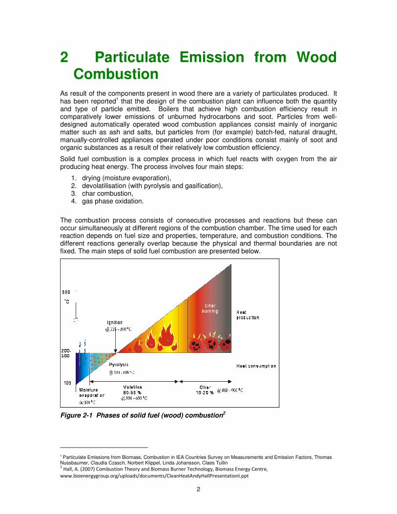
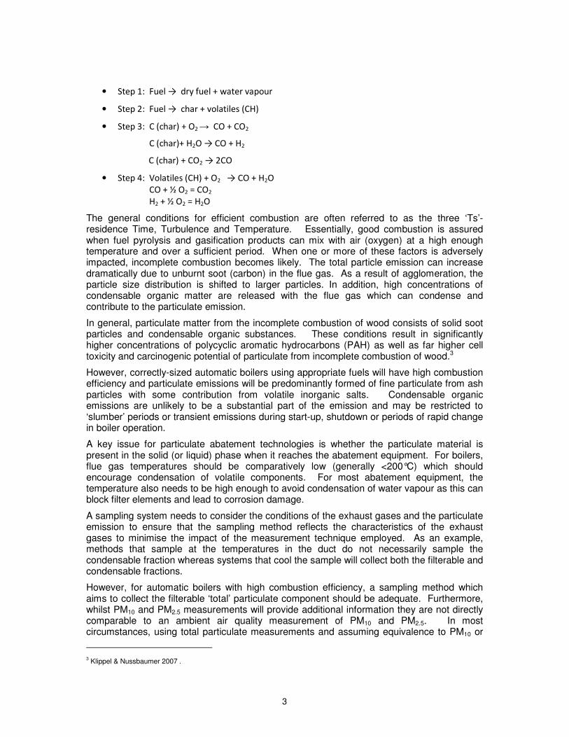
Solid fuel combustion is a complex process in which fuel reacts with oxygen from the air producing heat energy. The process involves four main steps:
1. drying (moisture evaporation), 2. devolatilisation (with pyrolysis and gasification), 3. char combustion, 4. gas phase oxidation.
The combustion process consists of consecutive processes and reactions but these can occur simultaneously at different regions of the combustion chamber. The time used for each reaction depends on fuel size and properties, temperature, and combustion conditions. The different reactions generally overlap because the physical and thermal boundaries are not fixed. The main steps of solid fuel combustion are presented below.
Figure 2-1 Phases of solid fuel (wood) combustion2
1 Particulate Emissions from Biomass, Combustion in IEA Countries Survey on Measurements and Emission Factors, Thomas Nussbaumer, Claudia Czasch, Norbert Klippel, Linda Johansson, Claes Tullin 2 Hall, A. (2007) Combustion Theory and Biomass Burner Technology, Biomass Energy Centre,
www.bioenergygroup.org/uploads/documents/CleanHeatAndyHallPresentationI.ppt
3
• Step 1: Fuel → dry fuel + water vapour
• Step 2: Fuel → char + volatiles (CH)
• Step 3: C (char) + O2 → CO + CO2
C (char)+ H2O → CO + H2
C (char) + CO2 → 2CO
• Step 4: Volatiles (CH) + O2 → CO + H2O
CO + ½ O2 = CO2
H2 + ½ O2 = H2O
The general conditions for efficient combustion are often referred to as the three ‘Ts’- residence Time, Turbulence and Temperature. Essentially, good combustion is assured when fuel pyrolysis and gasification products can mix with air (oxygen) at a high enough temperature and over a sufficient period. When one or more of these factors is adversely impacted, incomplete combustion becomes likely. The total particle emission can increase dramatically due to unburnt soot (carbon) in the flue gas. As a result of agglomeration, the particle size distribution is shifted to larger particles. In addition, high concentrations of condensable organic matter are released with the flue gas which can condense and contribute to the particulate emission.
In general, particulate matter from the incomplete combustion of wood consists of solid soot particles and condensable organic substances. These conditions result in significantly higher concentrations of polycyclic aromatic hydrocarbons (PAH) as well as far higher cell toxicity and carcinogenic potential of particulate from incomplete combustion of wood.3
However, correctly-sized automatic boilers using appropriate fuels will have high combustion efficiency and particulate emissions will be predominantly formed of fine particulate from ash particles with some contribution from volatile inorganic salts. Condensable organic emissions are unlikely to be a substantial part of the emission and may be restricted to ‘slumber’ periods or transient emissions during start-up, shutdown or periods of rapid change in boiler operation.
A key issue for particulate abatement technologies is whether the particulate material is present in the solid (or liquid) phase when it reaches the abatement equipment. For boilers, flue gas temperatures should be comparatively low (generally <200°C) which should encourage condensation of volatile components. For most abatement equipment, the temperature also needs to be high enough to avoid condensation of water vapour as this can block filter elements and lead to corrosion damage.
A sampling system needs to consider the conditions of the exhaust gases and the particulate emission to ensure that the sampling method reflects the characteristics of the exhaust gases to minimise the impact of the measurement technique employed. As an example, methods that sample at the temperatures in the duct do not necessarily sample the condensable fraction whereas systems that cool the sample will collect both the filterable and condensable fractions.
However, for automatic boilers with high combustion efficiency, a sampling method which aims to collect the filterable ‘total’ particulate component should be adequate. Furthermore, whilst PM10 and PM2.5 measurements will provide additional information they are not directly comparable to an ambient air quality measurement of PM10 and PM2.5. In most circumstances, using total particulate measurements and assuming equivalence to PM10 or
3 Klippel & Nussbaumer 2007 .
4
PM2.5 will be adequate to assess air quality impact because this provide a ‘worst case’ situation for assessing an air quality impact. There are general ‘default’ size fractionation factors in the literature if needed4 (and these indicate that for biomass combustion most of the particulate emitted is PM2.5).
4 For example the size fractionation can be derived from the EMEP/EEA air pollutant emission inventory guidebook available here : http://www.eea.europa.eu/publications/emep-eea-emission-inventory-guidebook-2009
5
3 Standard Particulate Measurement Methods
3.1 Periodic, Integrated and Continuous Methods
Most Standard methods used for assessment of abatement and environmental performance are periodic measurements undertaken over a comparatively short period of time. These periodic methods are generally integrated methods (they collect a sample over a period) but there are periodic methods which can provide continuous or near continuous data.
Note that there are also Standards for continuous automated measurement systems (AMS) for particulate which use a variety of physical measurement techniques to determine particulate concentration in exhaust gas. Calibration of AMS is undertaken by comparison against Standard integrated gravimetric methods. In the UK, an AMS is generally required only on larger combustion installations or where boilers are burning waste-derived fuels (that is where the installation or activity falls under pollution prevention and control regulation).
3.2 General principles of integrated measurements
The particulate measurement Standards considered in this report are all integrated gravimetric methods which collect particulate from a sample of flue gas collected over a known time interval and determine the concentration from the mass collected in the sampled volume.
There are a number of recognised International and National Standards that are used to determine the emission of particulate material from stationary sources. These are applicable to combustion and other sources but may have been developed for use on processes with more potential for impact on the environment (such as large power station boilers). However, the methods are also suitable for determining the emission of particulate material from biomass combustion.
Methods for the measurement of particulate emissions are designed to ensure a representative sample is obtained taking into account the inertial effects associated with particulates. The features of an acceptable method are defined below; the information is largely based on the requirements of EN13284-1 (See Section 3.3 ) but ISO and many National Standards have similar requirements (see Sections 3.3 – 3.7).
3.2.1 Position of the sample plane
The position of the sample plane can have a significant impact on the measurement of particulate material due to range of particle size and mass of particulate material generated during the combustion process. These physical characteristics result in ‘inertial effects’ giving rise to a separating of differing particle characteristics which in turn results in difficulties in obtaining a representative sample of the emission. The sample plane should be positioned such that these inertial effects are eliminated or reduced to a minimum. This requires the sample plane to be as far as possible both upstream and downstream from any obstruction that results in a disturbance. In addition, EN 13284-1 defines the acceptable physical characteristics as
• The angle of gas flow is less than 15° to duct axis, • No local negative flow, • Minimum velocity produces a differential pressure of 5 Pa, • Ratio of highest to lowest velocities across the profile is 3:1
6
The plane should be demonstrated as being homogenous in nature. The procedure is described in EN 15259 (see Section 5).
3.2.2 Number of Sample points
The number of sample points is chosen to sample a representative proportion of the sample plane. The number of sampling points impacts on how representative the sample collected is and hence the uncertainty of the measurement. The minimum number of sample points is dependent on the area of the duct. The sampling points are located at the centre of equal areas over the sample plane. For small circular ducts i.e. <0.35m2 (less than about 0.66m diameter) meeting the sample plane requirements of the Standard, a single central point is acceptable.
3.2.3 Configuration of sample system
There are two configurations for the sample system;
• In-stack - the filter collection system is in the duct and; • Ex-stack – the filter housing is outside the duct and maintained at a suitable
temperature to ensure that there is no condensation or loss of sample.
However, for small boilers, a key issue is the size of the sample equipment as it can obstruct the duct and influence the measurements. As a guide, if the area of sampling assembly is 5%5 or greater of the duct area then ex-stack sampling should be adopted with only the sample nozzle, probe, pitot and temperature measurement in the stack. For very small boilers, use of a full flow dilution tunnel may be appropriate as it allows easier application of a Standard method.
3.2.4 Sample Nozzle Design
The sample nozzle should be sharp edged so as not to disturb the flow around the nozzle and hence impact the sample taken. The nozzle design should be such that the internal surfaces do not present surfaces for deposition and should meet the criteria given in the standard.
3.2.5 Materials of Construction
The materials used throughout the system both internal and external should not be reactive to components in the gas stream.
3.2.6 Test Period
This should be a minimum of 30 minutes.
3.2.7 Isokinetic sampling
This is sampling at a flow rate which results in a velocity at the nozzle that is the same as the velocity within the stack at the point being sampled. This avoids any bias towards either large or small particle sizes caused by the inertial effects associated with particles so ensuring a representative sample is collected.
3.2.8 Velocity Monitoring
Whilst sampling, the velocity at the sample plane should be simultaneously monitored (for manual methods this should be checked every 5 minutes) to check for flow variations and enable adjustments to the sample flow rate ensuring isokinetic conditions are maintained.
5 From USEPA Method 17 – Determination of particulate matter emissions from stationary sources
7
3.2.9 Temperature, pressure and composition measurements
These measurements should be made to calculate the actual density of gas stream to ± 0.05 kg.m-3.
3.2.10 Filter media
Collection with an efficiency of >99.5 % on a test aerosol of aerodynamic diameter of 0.3µm. This performance criterion should be certified by the filter manufacturer. This media should be conditioned prior to use to prevent media loss during testing.
3.2.11 Filter temperature
This is a key difference between methods and may impact collection or retention of some of the particulate emission.
3.2.12 Leak Checking
The sample system should be checked for leaks prior to and after each test, in addition at any point during the test when the probe system is disassembled during a test (for example to move to a new sample line).
3.2.13 Sample Blank
A sample blank should be taken prior to the commencement of a series of tests. This involves going through the test procedure with the exclusion of actual sampling, this includes assembly, leak checks, sample and deposit collection. There is a limit on the magnitude of the blank value when used to assess against an emission limit value. The blank, assessed using data from the measurement series, shall not exceed 10 % of the emission limit value.
3.2.14 Measured Sample volume
The metering system should be capable of measuring with an uncertainty of ±2.0 %
3.2.15 Clean-up procedure and deposit recovery
Sampled material from parts of the sample system prior to the collection media should be collected and added to the filter media captured material.
3.2.16 Weighing procedure
A validated weighing procedure shall be adopted.
3.3 European Committee for Standardisation (CEN)
CEN Standards are adopted and published by national standardisation authorities (replacing pre-existing national standards). For the UK the British Standards Institute (BSI) is the national authority and EN Standards are adopted as British Standards. For example EN 13284-1:2001 (see below) has been adopted by BSI as BS EN 13284-1:2002.
3.3.1 EN 13284-1:2001
Stationary source emissions – Determination of mass concentration of particulate matter (dust) at low concentrations – Part 1: Manual gravimetric method
This method is applicable to particulate material concentrations below 50 mg.m-3 however, the principles can also be applied at higher concentrations (for example upstream of abatement equipment).
The standard defines the design and performance of the equipment to be used. The position of the sample plane is defined to eliminate or reduce the influence of inertial effects
8
associated with particulate material and the variation in flow direction and amplitude as much as practicable.
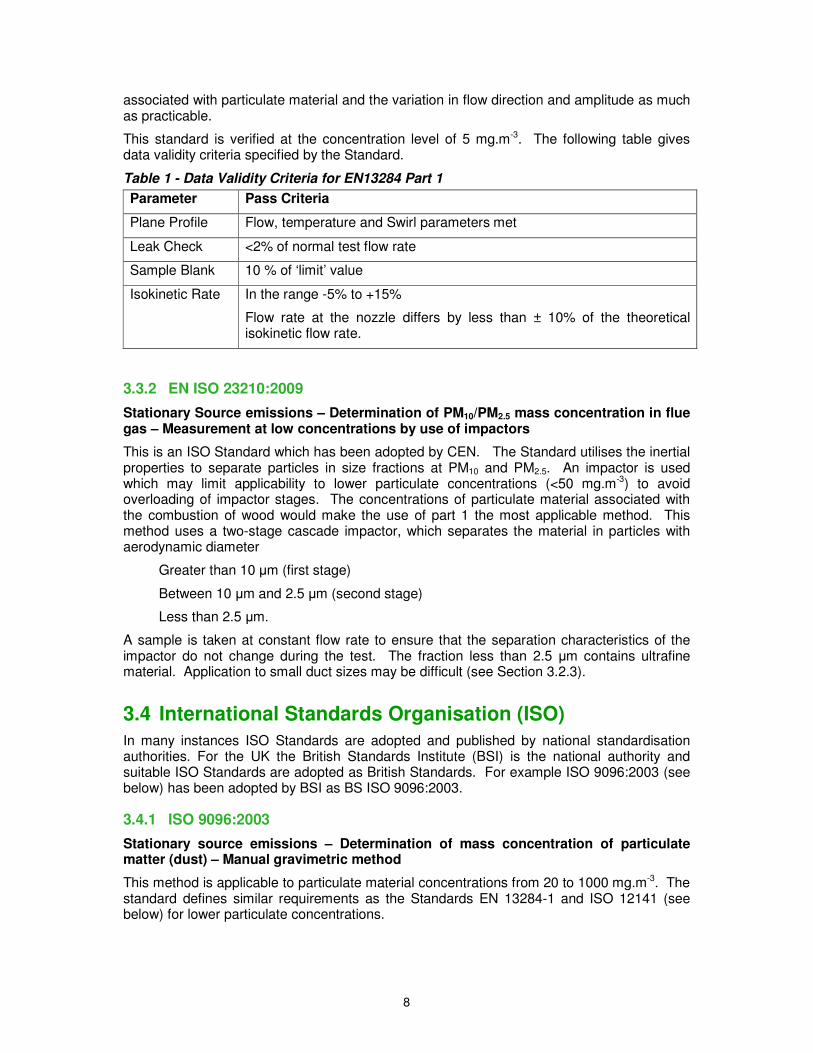
This standard is verified at the concentration level of 5 mg.m-3. The following table gives data validity criteria specified by the Standard.
Table 1 - Data Validity Criteria for EN13284 Part 1
Parameter Pass Criteria
Plane Profile Flow, temperature and Swirl parameters met
Leak Check <2% of normal test flow rate
Sample Blank 10 % of ‘limit’ value
Isokinetic Rate In the range -5% to +15%
Flow rate at the nozzle differs by less than ± 10% of the theoretical isokinetic flow rate.
3.3.2 EN ISO 23210:2009
Stationary Source emissions – Determination of PM10/PM2.5 mass concentration in flue gas – Measurement at low concentrations by use of impactors
This is an ISO Standard which has been adopted by CEN. The Standard utilises the inertial properties to separate particles in size fractions at PM10 and PM2.5. An impactor is used which may limit applicability to lower particulate concentrations (<50 mg.m-3) to avoid overloading of impactor stages. The concentrations of particulate material associated with the combustion of wood would make the use of part 1 the most applicable method. This method uses a two-stage cascade impactor, which separates the material in particles with aerodynamic diameter
Greater than 10 µm (first stage)
Between 10 µm and 2.5 µm (second stage)
Less than 2.5 µm.
A sample is taken at constant flow rate to ensure that the separation characteristics of the impactor do not change during the test. The fraction less than 2.5 µm contains ultrafine material. Application to small duct sizes may be difficult (see Section 3.2.3).
3.4 International Standards Organisation (ISO)
In many instances ISO Standards are adopted and published by national standardisation authorities. For the UK the British Standards Institute (BSI) is the national authority and suitable ISO Standards are adopted as British Standards. For example ISO 9096:2003 (see below) has been adopted by BSI as BS ISO 9096:2003.
3.4.1 ISO 9096:2003
Stationary source emissions – Determination of mass concentration of particulate matter (dust) – Manual gravimetric method
This method is applicable to particulate material concentrations from 20 to 1000 mg.m-3. The standard defines similar requirements as the Standards EN 13284-1 and ISO 12141 (see below) for lower particulate concentrations.
9
3.4.2 ISO 12141:2002
Stationary source emissions – Determination of mass concentration of particulate matter (dust) at low concentrations – Manual gravimetric method
This method is similar to EN 13284-1 being applicable to a lower range than ISO 9096. However, unlike EN 13284-1 emphasis is given to high volume samplers which by their nature increase the size of the sample collected.
In addition there is an ISO Standard designed to measure specific size fractions of the emission and two related standards are in development.
3.4.3 ISO 23210:2009 (BS ISO EN 23210:2009)
Stationary Source emissions – Determination of PM10/PM2.5 mass concentration in flue gas – Measurement at low concentrations by use of impactors.
See Section 3.3.2.
3.4.4 Draft ISO Standards for particle size determination
These methods are devised to determine the primary particles that are emitted from a source, not dealing with the condensable fraction. The method uses size-selective separation of the particles in the gas stream and gravimetric determination of the collected fractions to determine the concentration present in a volume of sampled gas.
• ISO/CD 13271 Stationary source emissions -- Determination of PM10/PM2.5 mass concentration in flue gas -- Measurement at higher concentrations by use of virtual impactors. .
• ISO/WD 25597 Stationary Source emissions – Test method for determining PM2.5 and PM10 mass in stack gases using cyclone samplers and sample dilution.
The size of the separation devices may prevent use in small ducts common in smaller biomass installations without adapting the method (see Section 3.2.3).
3.5 United Kingdom
UK reference methods for particulate emission are adopted EN and ISO methods. There is a BS for determining smoke darkness (BS 2742:2009) and there are also British Standards for specific applications which include particulate measurement but these are generally not considered appropriate for emission testing on boilers. BS3841 Part 2:1994 provides a methodology for assessing particulate emissions from residential solid fuel boilers, however, it is not believed to be suitable for larger appliances and is intended for deployment at a test laboratory.
3.6 Germany
CEN standard sampling methods are adopted by the German Standards organisation (DIN) but the Association of German engineers (VDI)6 also lists several guidelines for particulate measurement.
6 Information here www.vdi.eu
10
3.6.1 VDI 2066 Part 1
Particulate matter measurement - Dust measurement in flowing gases - Gravimetric determination of dust load (revised 2006)
This revised methodology is stated to be similar to EN13284-1.
3.6.2 VDI 2066 Part 5
Particulate matter measurement - Dust measurement in flowing gases; particle size selective measurement by impaction method - Cascade impactor (1994)
This method is suitable for particle sizing including PM10 and PM2.5. The size of the impactor is likely to be a constraint on use at small boilers (see Section 3.2.3).
3.6.3 VDI 2066 Part 10
Particulate matter measurement - Dust measurement in flowing gases - Measurement of PM10 and PM2.5 emissions at stationary sources by impaction method (2004)
This method is understood to have formed the basis of EN ISO 23210 but does not appear to have been withdrawn in favour of the adopted EN.
VDI 2066 Parts 2, 3, 4, 6 and 7 also covered particulate measurement but have been withdrawn. VDI 2066 Part 8 applies to oil-fired furnaces and measures smoke number.
3.7 United States
3.7.1 US Environmental Protection Agency
The US Environmental Protection Agency (USEPA)7 lists a number of sampling standards for the measurement of particulate material from stationary sources:
• Method 5 – Determination of the Particulate Matter Emissions from Stationary Sources
• Method 5I—Determination of Low Level Particulate Matter Emissions from Stationary Sources
• Method 17 - Determination of the Particulate Matter Emissions from Stationary Sources (in-stack method)
Methods 5, 5I and 17 follow similar principles to that of the CEN and ISO standards. However, a specific design of equipment is specified and the filtration temperature is fixed at 120°C. The approach uses isokinetic sampling to ensure that sampling does not influence the particle sizes sampled ensuring that the sample is representative of the emission. Metod 17 adopts an in-stack location for the sample filter which is unlikely to be suitable for the smallest boilers (see Section 3.2.3).
In addition to these methods the USEPA has published two methods for wood stoves, these are not applicable to larger boilers but illustrate methods for capturing filterable and condensable emissions.
Method 5G – Particulate Matter emissions from Wood Heaters using a Dilution Tunnel. The sampling train differs from the Standard Method 5 systems in that the particulate material is collected on two fibre filters in series compared to the single filter used on Method 5. The filters are also maintained at a lower temperature, i.e. 32°C as compared to the 120°C, than used for Method 5 sampling.
7 Methods available from http://www.epa.gov/ttn/emc/tmethods.html#CatA
11
In addition the sample is taken from a single position in a collection hood and sampling tunnel that collects the total emission from the process/unit which is mixed with dilution air.
Method 5H - Determination of particulate matter emissions from wood heaters from a stack location. This method is more similar than Method 5G to Method 5, since the filter is maintained at 120°C. Although, a dual filter sampling train from a single point is used, as in Method 5G, the two filters are separated by the impingers.
In addition, the USEPA has published methods to determine specific size fractions found within emissions from stationary sources. :
• Method 201 Determination of PM10 Emissions (Exhaust Gas Recycle method)
• Method 201A Determination of PM10 Particulate Emissions (constant sampling rate procedure)
• Method 202 Determination of Condensable Particulate Emissions from Stationary Sources
Method 201 uses specialist sample flow control equipment and is more complex than Method 201A which uses the same flow controller as for Method 5. Methods 201 and 201A uses a cyclone to separate a PM10 fraction; the cyclone is deployed in-stack and hence the method is unlikely to be suitable for the smallest boiler sizes (see Section 3.2.3). Method 202 allows determination of condensable emissions by modifying the post-filter sampling train and recovery procedures of the other methods.
The USEPA has also published ‘Conditional Test Methods’ and ‘Other Test Methods’ – these are not approved alternative methods but methods which may, in certain circumstances, provide suitable data.
Conditional test methods:
• CTM 2 – Determination of particulate matter (screening procedure)
• CTM 3 - Determination of particulate matter (modified high volume sampling procedure)
• CTM 39 – Measurement of PM2.5 and PM10 emissions by dilution sampling (constant sampling rate procedures)
Other Test Methods:
• OTM 27 – Determination of PM2.5 and PM10 emissions by dilution sampling (constant sampling rate procedures)
3.7.2 American Society for Testing and Materials
The most relevant ASTM Standards are:
• ASTM D3685 / D3685M - 98(2005) Standard Test Methods for Sampling and Determination of Particulate Matter in Stack Gases
• ASTM D6331 - 98(2005) Standard Test Method for Determination of Mass Concentration of Particulate Matter from Stationary Sources at Low Concentrations (Manual Gravimetric Method)
These are believed to reflect USEPA and ISO Methods.
12
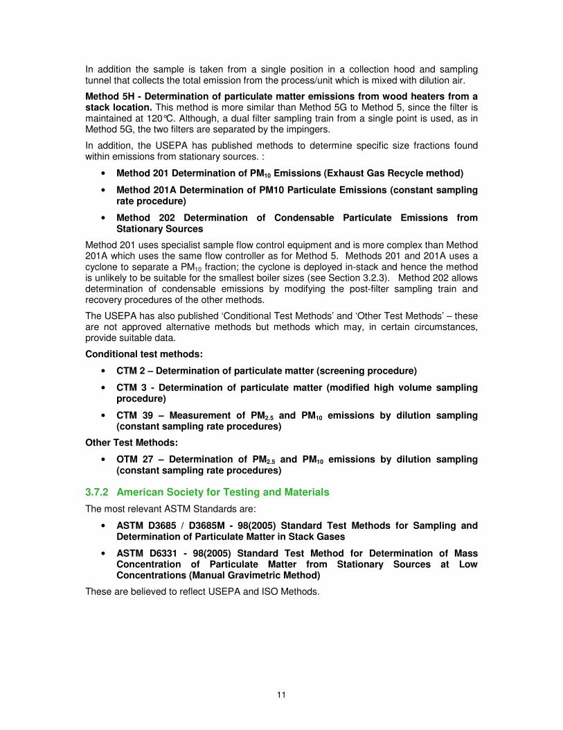
3.8 Summary of Standard integrated methods for total particulate, PM10 and PM2.5
International Standards and common National Standards/methods for particulate measurement are summarised in Table . International Standards and common national methods for PM10 and PM2.5 determination are provided in Table 3. Tables 2 and 3 also suggest whether the methods are suitable for emissions testing of small boilers.
Table 2 Summary of Standard Total Particulate Measurement Methods
Source Standard Description Applicability to smaller
boilers
CEN EN 13284-1:2001
Stationary source emissions – Determination of mass concentration of particulate matter (dust) at low concentrations – Part 1: Manual gravimetric method.
Y
ISO ISO 9096:2003 Stationary source emissions – Determination of mass concentration of particulate matter (dust)– Manual gravimetric method.
Y
ISO ISO 12141:2002 Stationary source emissions – Determination of mass concentration of particulate matter (dust) at low concentrations – Manual gravimetric method.
Y
VDI (Germany)
VDI 2066 Part 1 Particulate matter measurement - Dust measurement in flowing gases - Gravimetric determination of dust load (revised 2006). This revised methodology is stated to be similar to EN13284-1.
Y
USEPA (USA)
Method 5 Determination of the Particulate Matter Emissions from Stationary Sources.
Y
USEPA Method 5I Determination of Low Level Particulate Matter Emissions From Stationary Sources.
Y
USEPA Method 17 Determination of the Particulate Matter Emissions from Stationary Sources (in-stack method).
N
ASTM (USA)
ASTM D3685 / D3685M - 98(2005)
Standard Test Methods for Sampling and Determination of Particulate Matter in Stack Gases.
Not known
ASTM ASTM D6331 - 98(2005)
Standard Test Method for Determination of Mass Concentration of Particulate Matter from Stationary Sources at Low Concentrations (Manual Gravimetric Method).
Not known
13
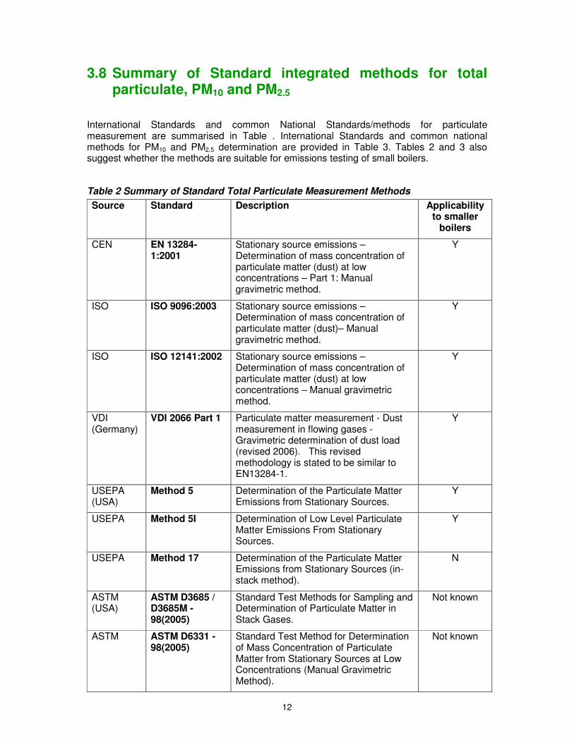
Table 3 Summary of Standards and methods for PM10 and PM2.5
Source Standard Description Applicability to smaller
boilers
EN/ISO EN ISO 23210:2009
Stationary Source emissions – Determination of PM10/PM2.5 mass concentration in flue gas– Measurement at low concentrations by use of impactors.
N
VDI (Germany)
VDI 2066 Part 5 Particulate matter measurement - Dust measurement in flowing gases; particle size selective measurement by impaction method - Cascade impactor (1994). Suitable for particle sizing including PM10 and PM2.5.
N
VDI VDI 2066 Part 10 Particulate matter measurement - Dust measurement in flowing gases - Measurement of PM10 and PM2.5 emissions at stationary sources by impaction method (2004).
N
USEPA (USA)
CTM 39 Measurement of PM2.5 and PM10 emissions by dilution sampling (constant sampling rate procedures)
N
USEPA (PM10)
Method 201 Determination of PM10 Emissions (Exhaust Gas Recycle method)
N
USEPA (PM10)
Method 201A Determination of PM10 Particulate Emissions(constant sampling rate procedure)
N
USEPA (PM10)
Method 202 Determination of Condensable Particulate Emissions from Stationary Sources.
Y
Note that use on smaller boilers may be possible by modifying methodology to accommodate in-stack separation devices outside the stack (for example in a heated oven) or by applying a full flow dilution tunnel to provide a larger diameter duct for sampling. However, both these approaches can affect the material sampled and deployment of a dilution tunnel may not be practical outside a laboratory.
14
4 Other Particulate Measurement Techniques
In addition to the methods listed in Section 3, there are a number of techniques that are used to determine particulate material concentration, size distribution and composition. The Standard methods tend to involve discontinuous gravimetric sampling whereas some of these other techniques provide continuous or near continuous sampling and parameter determination.
4.1 US Dilution tunnel research
Following introduction in 1997 of US National Ambient Air Quality Standards for particulate matter and PM2.5 concerns arose about apparently high emission test results obtained by the USEPA methods 201, 201A and 202 on gas combustion processes and consequently the potential impact on air quality.
The ‘traditional’ stack emission test methods do not account properly for primary aerosol formation and the materials that form PM2.5 after the gases leave the stack. In response to these concerns the US Department of Energy Technology Laboratory (DOE/NETL), California Energy Commission (CEC), Gas Research Institute (GRI), New York State Energy Research and development Authority (NYSERDA) and the American Petroleum Institute (API) commissioned a project, the aim of which was to:
Develop improved dilution sampling technology for measurement and speciation of PM2.5;
Identify PM2.5 precursor compounds from stationary sources; and
Develop emission factors and profiles from oil and gas power generation sectors.
Dilution methodology was chosen as it produced an environment in which secondary particles would form resulting in the ability to physically quantify the contribution of a process to the environment.
As part of the project a topical report8 was issued that outlined a fine particulate test protocol. This protocol was based on the use of the dilution system that had been developed during the project9.
The system comprises of a cyclone arrangement to separate out either PM2.5 or PM10 and a heated probe through which the sampled emission passes into a dilution system where the sample is rapidly mixed with clean dry dilution air. Guidelines on dilution ratios and temperatures are given as these factors affect the formation of agglomeration and size distribution. The dilution system approximates to the processes that occur at the point of leaving a stack and entering the environment. These processes are further encouraged by passing the sample into a residence chamber where nucleation and condensation processes are allowed to go to completion. The particulate material is then collected on a single stage Teflon membrane filter and measured gravimetrically. The dilution system also allows subsequent analysis to determine the composition of the material formed.
8 England, G.C and McGarth, T.P., Development of Fine Particulate Emissions Factors and Speciation Profiles for Oil and Gas-Fired Combustion Systems, Topical Report: Fine Particulate Test Protocol. 9 Final report available here : http://www.nyserda.org/programs/environment/emep/08_CriticalReviewUpdate_R1-V0.pdf
15
Although field testing using the dilution tunnel approach was demonstrated, the measurement protocol has not been adopted by USEPA but the work has provided input to conditional test methods for determination of PM10 and PM2.5 at stationary sources.
4.2 Tapered element oscillating micro-balance (TEOM)
The TEOM is a well-established instrument used for the continuous measurements of PM10
and PM2.5. Often used with a dilution system when used to measure the emissions from processes involving combustion. The system comprises of an oscillating filament. The change in oscillation can be related directly to the mass of particulate material adhering to the filter element attached to the filament.
4.3 Measurements of particle size distributions
The measurement of particulate size has become of significant interest as this influences the lifetime of the particles in the ambient air and the separation efficiency in the human respiratory tract and the impact that this can have on human health. There have been several studies that show biomass combustion can contribute to smaller particulate size range due to the condensable fraction that is present in the emission. The following techniques enable the measurement of size, mass and number.
4.3.1 Scanning Mobility Particle Sizer (SMPS)
Electrical mobility aerosol analysers such as the SMPS are based on the movement of gas-borne particles carrying a known electric charge towards an electrode of opposite charge. These techniques are widely used, especially in particle formation studies, since they have the potential for very good size resolution in the range 0.01 to 1.0 µm diameter.
Electrical mobility analysers are widely used to size particles in the range 0.004 to 1 µm volume equivalent diameter. Particles much smaller than this lower limit are difficult to charge, whereas multiple charging becomes a problem with micron-sized and larger particles.
Differential mobility analysers (DMAs) have been developed to capture the narrow range of particles that have a common trajectory within an electrical mobility analyser. They typically consist of an Electrostatic Classifier as the mobility analyser, which is coupled to a continuous flow condensation nucleus counter (CNC).
Scans can be achieved in as little as 60 s at very high resolution (64 channels per decade of size). In the Scanning Mobility Particle Sizer (SMPS) the electric field strength in the electrical classifier section is varied monotonically, at the same time making particle number concentration measurements in rapid succession (as much as 10 times per second) using a condensation nuclei counter.
4.3.2 Particle Counter
This is a condensation particle counter (CPC) that operates in a similar manner to that used in the SMPS system. The CPC counts particles with diameters between 5 nm and 4 µm at concentrations of up to 107 particles.cm-3 at a frequency of 1 Hz (1 data point per second).
The aerosol particles enter via the sampling tube to the Saturator, where they cross a heated (35°C) N-butyl-alcohol saturation pipe. There the aerosol is exposed to the alcohol vapour. Particles and vapour then flow into the cooling condenser unit (10°C), where the supersaturated vapour condenses on all the particles as they pass through. This process increases the particle size. These droplets then cross a laser beam where each droplet scatters light onto a photodiode. These signals are continuously counted and are expressed
16
in particles.cm-3 each second. These counts are then stored as data and also transmitted via the RS-232 to an external data acquisition device.
4.3.3 Aerosol Diluter
In most applications dilution is needed to avoid overloading the counter, however, dilution of hot gases containing volatile materials can also introduce additional errors due to condensation effects (see below). A rotating disc diluter allows hot or cold dilution.
A circular disc containing up to 10 cavities transports small volumes of exhaust gas to a measurement channel. There are two separate gas channels: the raw gas channel and the diluted measurement channel, as raw gas is rotated it is diluted with particle free air. The ratio of dilution of raw gas is a linear function of the cavity volume, the number of cavities on the disc, the frequency of rotation, and the flow in the diluted gas channel.
4.3.4 Thermal Conditioner
Used in conjunction with a rotating disc diluter, the diluter and thermoconditioner are connected together to produce a thermodiluter, which is designed to suppress volatile particles. Any hot exhaust gas stream can potentially contain both solid particles and vapours of volatile substances (water, sulphate, hydrocarbons). Measurement of the hot aerosols from ducts often cause the volatile particles to condense into nano-droplets which are then detected as particles together with the solid particles. Hot aerosols are more stable making their measurement repeatable if the solid particle fraction is measured independently from the volatile particles and it is preferable to remove this fraction when trying to produce repeatable results.
4.3.5 Portable aerosol spectrometer
An aerosol spectrometer is an instrument based on the technique of light scattering. It provides single particle count and size classification in real time. The aerosol is constantly drawn through the instrument and passed through a flat light beam, produced by a focused laser diode. Each scattered signal from a single particle is detected by a high speed photo diode. Each signal is then counted and classified in 15 different size channels by an integrated pulse height analyzer.
The spectrometer produces data in a number of particle count channels (for particles with diameter between 0.3 and 20 µm) to produce particle size distribution. Instruments can also operate in “mass mode” to produce mass distributions (µg.m-3) via an internal calibration factor which takes into account the particle density.
17
5 Supporting Measurements
5.1 Overview
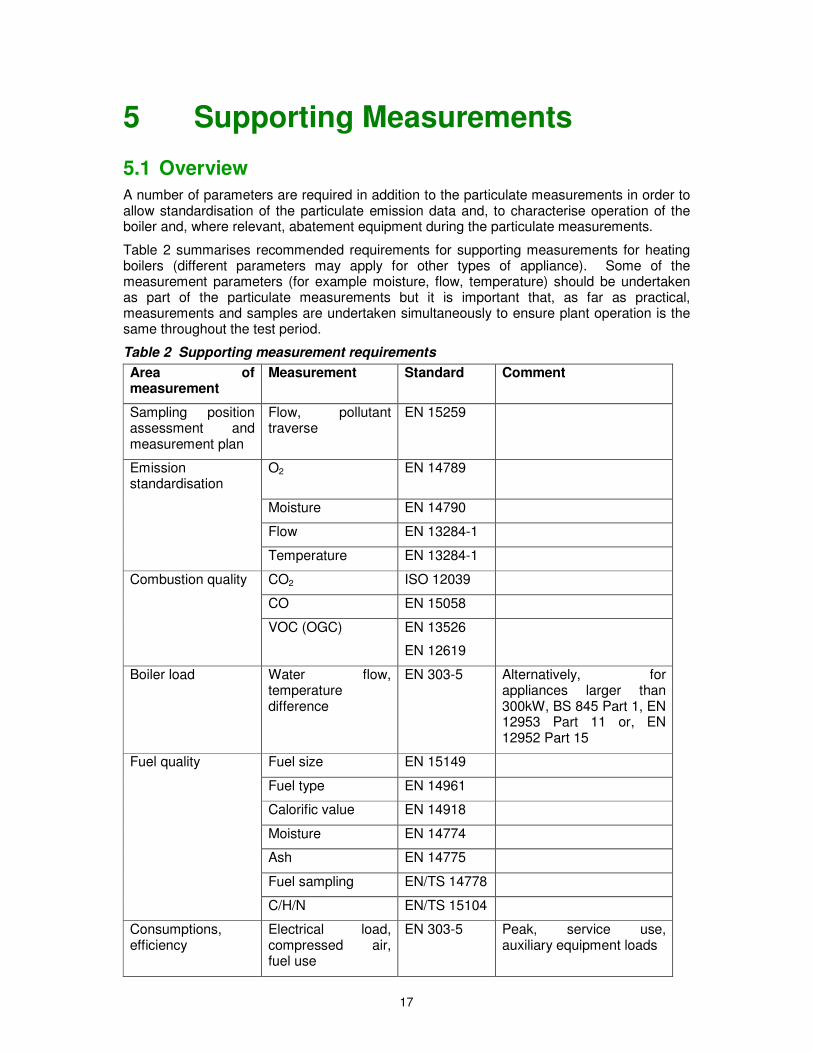
A number of parameters are required in addition to the particulate measurements in order to allow standardisation of the particulate emission data and, to characterise operation of the boiler and, where relevant, abatement equipment during the particulate measurements.
Table 2 summarises recommended requirements for supporting measurements for heating boilers (different parameters may apply for other types of appliance). Some of the measurement parameters (for example moisture, flow, temperature) should be undertaken as part of the particulate measurements but it is important that, as far as practical, measurements and samples are undertaken simultaneously to ensure plant operation is the same throughout the test period.
Table 2 Supporting measurement requirements
Area of measurement
Measurement Standard Comment
Sampling position assessment and measurement plan
Flow, pollutant traverse
EN 15259
Emission standardisation
O2 EN 14789
Moisture EN 14790
Flow EN 13284-1
Temperature EN 13284-1
Combustion quality CO2 ISO 12039
CO EN 15058
VOC (OGC) EN 13526
EN 12619
Boiler load Water flow, temperature difference
EN 303-5 Alternatively, for appliances larger than 300kW, BS 845 Part 1, EN 12953 Part 11 or, EN 12952 Part 15
Fuel quality Fuel size EN 15149
Fuel type EN 14961
Calorific value EN 14918
Moisture EN 14774
Ash EN 14775
Fuel sampling EN/TS 14778
C/H/N EN/TS 15104
Consumptions, efficiency
Electrical load, compressed air, fuel use
EN 303-5 Peak, service use, auxiliary equipment loads
18
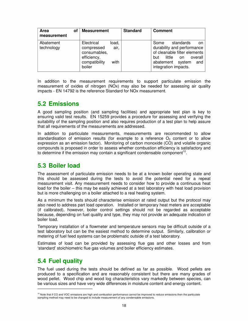
Area of measurement
Measurement Standard Comment
Abatement technology
Electrical load, compressed air, consumables, efficiency, compatibility with boiler
Some standards on durability and performance of cleanable filter elements but little on overall abatement system and integration impacts.
In addition to the measurement requirements to support particulate emission the measurement of oxides of nitrogen (NOx) may also be needed for assessing air quality impacts - EN 14792 is the reference Standard for NOx measurement.
5.2 Emissions
A good sampling position (and sampling facilities) and appropriate test plan is key to ensuring valid test results. EN 15259 provides a procedure for assessing and verifying the suitability of the sampling position and also requires production of a test plan to help assure that all requirements of the measurements are addressed.
In addition to particulate measurements, measurements are recommended to allow standardisation of emission results (for example to a reference O2 content or to allow expression as an emission factor). Monitoring of carbon monoxide (CO) and volatile organic compounds is proposed in order to assess whether combustion efficiency is satisfactory and to determine if the emission may contain a significant condensable component10.
5.3 Boiler load
The assessment of particulate emission needs to be at a known boiler operating state and this should be assessed during the tests to avoid the potential need for a repeat measurement visit. Any measurement needs to consider how to provide a continuous heat load for the boiler – this may be easily achieved at a test laboratory with heat load provision but is more challenging on a boiler attached to a real heating system.
As a minimum the tests should characterise emission at rated output but the protocol may also need to address part load operation. Installed or temporary heat meters are acceptable (if calibrated), however, boiler control settings should not be regarded as acceptable because, depending on fuel quality and type, they may not provide an adequate indication of boiler load.
Temporary installation of a flowmeter and temperature sensors may be difficult outside of a test laboratory but can be the easiest method to determine output. Similarly, calibration or metering of fuel feed systems can be problematic outside of a test laboratory.
Estimates of load can be provided by assessing flue gas and other losses and from ‘standard’ stoichiometric flue gas volumes and boiler efficiency estimates.
5.4 Fuel quality
The fuel used during the tests should be defined as far as possible. Wood pellets are produced to a specification and are reasonably consistent but there are many grades of wood pellet. Wood chip and wood log characteristics vary markedly between species, can be various sizes and have very wide differences in moisture content and energy content. 10 Note that if CO and VOC emissions are high and combustion performance cannot be improved to reduce emissions then the particulate sampling method may need to be changed to include measurement of any condensable emissions.
19
EN303-5 (for solid fuel central heating boilers up to 300 kW output) includes several generic commercial fuel definitions but there are also a suite of Standards and Technical Specifications produced by CEN TC335 on solid biofuels which also define fuel classes.
The fuel should be classified in accordance with the TC335 Standards and Technical Specifications on solid biofuel.
5.5 Consumptions and efficiency
Consumptions and boiler efficiency are not essential to assess emission performance but may be relevant to characterising boiler operation during the tests. EN303-5 and other Standards for efficiency incorporate methodologies for determining fuel and other consumptions.
5.6 Abatement technology
Section 6 describes assessment Standards and other schemes for determining performance of particulate filter systems. However, these tend to be for specific elements of the abatement equipment (for example filter elements) or to relate to non-combustion activities (for example HEPA or clean room filter performance).
The primary approach to assess the performance of abatement equipment is to determine the release concentration which is often subject to an emission limit or other control measure – this provides a clear parameter to achieve.
Abatement or collection efficiency can also be determined by assessing inlet and outlet burdens – however, efficiency is usually less important than controlling release concentrations or rates. For example in filtration systems (ceramic filters and fabric filters) efficiencies are very high and can tolerate very high inlet burdens with only a small change (if any) in emission concentration. This is a key difference from a cyclone or electrostatic precipitator where emissions are more closely related to inlet burden. For example, fabric filter applications on systems incorporating sorbent injection (such as lime or sodium bicarbonate injection for acid gas removal) can cope with very much higher inlet particulate concentrations than arise from a simple combustion process.
Alternative assessment approaches include challenging the plant (or filter media) with known quantities of material of known characteristics – this can provide useful information but is usually applicable to defined types of dust or aerosol which may not reflect operation under real-life temperatures and other operating conditions.
20
6 Methodologies for Assessing Particulate Abatement Efficiency
6.1 United Kingdom Filter Testing
In the United Kingdom high efficiency (HEPA) filters are assessed by challenging them with particles of a known size. Also smoke generators are used to produce smoke particles containing a range of particle sizes. The filters are challenged with this smoke and assessed photometrically to determine the pre and post filter concentrations and hence the filter efficiency.
6.2 United States of America
The USEPA Environmental Technology Verification (ETV) Program11 was created to review, assess and encourage the development and the deployment of innovative or improved environmental technologies through performance verification and dissemination of information. This involves the development of quality test procedures, one of which is designed to evaluate the performance of bag filter products. The procedure has been developed in partnership with recognised standards, testing organisations and technology developers. All evaluations are conducted in accordance with rigorous quality assurance protocols to ensure that data of known and adequate quality are generated and that the results are defensible.
The Air Pollution Control Technology (APCT) Verification Center evaluates the performance of baghouse filtration products (BFPs) used primarily to control PM2.5 emissions.
The Generic Verification Protocol for Baghouse Filtration Products12 is based on and describes modifications to the equipment and procedures described in Verein Deutscher Ingenieure (VDI 3926, Part 2), Testing of Filter Media for Cleanable Filters under Operational Conditions, December 1994. However, this does not appear to be a current VDI Guideline. The protocol also includes requirements for quality management, quality assurance, procedures for product selection, auditing of the test laboratories, and test reporting format.
This involves the measurement of outlet particle concentrations from a test fabric being measured using an impactor designed to filter and collect material to enable the measurement of PM2.5 within the dust flow. These particle concentrations are determined by weighing the mass increase of dust collected in each impactor filter stage and dividing by the gas volumetric flow through the impactor.
Particle size is measured while injecting the test dust into the air upstream of the baghouse filter sample. The test dust is dispersed into the flow using a brush-type dust feeder. The particle size distributions in the air were determined both upstream and downstream of the test filter fabric to provide accurate results for penetration through the test filter of PM2.5. All tests are performed using a constant [identical to gas-to-cloth ratio (G/C)], and aluminium oxide test dust with a measured mass, products are tested in their initial (i.e. clean) condition.
11 Information here : http://www.epa.gov/etv/ 12 Generic Verification Protocol for Baghouse Filtration Products EPA Cooperative Agreement No. CR826152-01-3 RTI Project No. 93U-7012-25
21
6.3 CEN
6.3.1 Overview
CEN have produced a ‘Workshop Agreement’ (CWA) to provide technical review of abatement equipment and the measurements associated with the performance of air emissions abatement technologies:
CWA 16060:2009 Environmental technology verification. Air Emissions abatement technologies.
This reviews the procedures for verification of air emission abatement technologies but is not specific to abatement of wood combustion processes. A staged process is described:
• Organisation identifies verification interest • Vendor determines CWA requirements • Definition of verification claim and parameters needed to determine claim and impact
to environment (reviewed by independent expert) • Review of data from qualified party and assessment of need for further tests
(reviewed by independent expert), further testing if needed • Test report preparation • Review of test report (reviewed by independent expert) • Verification report • Statement of verification
In essence, the process requires the performance claims to be defined in terms of quantifiable parameters.
6.3.2 Test process
A test report will include a short explanation of the environmental technology, performance characteristics and performance claims.
General information on energy consumption and material consumption in production should be included. Installation requirements, instructions, any limitations of application should be included, as well as operator requirements, consumption and wastes in operation and, end-of-life disposal.
The test report shall include the performance claims supported by description and how quantification of the claims is to be demonstrated.
Independent review of the claims, verification proposals and supporting data is required for completeness and quality of data. A summary of existing and required information is to be provided.
The report shall give a testing strategy for verification including methods and justification for methods chosen. Testing is required to be by organisations with proven competence and preferably with ISO/IEC 17025 accreditation.
The test details to be recorded are also outlined in the CWA.
6.3.3 Verification
The aim is to assess whether test results verify the claims; an “external and independent” review of the test report is provided in a ‘review report’ which essentially judges the validity of the claims from the test results. The review report has to provide a justified evaluation with additional attention where results are not provided by independent test organisations.
Guidance is provided on the scope of the evaluation, key headings include evaluation of:
• Test implementation
22
• Quality of test results • Test results and results of reference method • Test results compared to the claims
A verification report is prepared comprising a short introductory summary, a test report, a review report, supported by any necessary annexes.
6.4 ISO
6.4.1 Overview
ISO have published a draft Standard:
ISO/DIS 11057 Test method for filtration characterisation of cleanable filter media.
It is based on German, Japanese, American and Chinese national Standards. The draft Standard is intended to provide a method for characterisation and evaluation of cleanable filter media (typically a cartridge or filter bag cleaned by a compressed air pulse). The aim of the draft Standard is to allow statements about the filtering properties of filter media in long-term operation. Design of filtering systems, selection of media are stated to be largely based on data obtained empirically from process plant or pilot plants.
The main purpose of testing is to characterise both the operational performance and the particle emission of cleanable filter media. Tests are conducted under controlled conditions and are intended to provide an indicative comparison of the operational behaviour of filter media – it may not give an accurate representation of field performance.
6.4.2 Test procedure
Filter media are placed in a test rig which is designed to expose the filter to a constant gas flow and a constant dust concentration with a repeatable compressed air cleaning cycle triggered when the pressure drop across the filter reaches a specific level. The DIS 11057 test rig is designed to assess flat flexible filter media but can be adapted for rigid filter elements (for example ceramic filter elements). A challenge concentration of 5 g.m-3 is applied with a filter face velocity (the average speed at which gas passes through the filter) of 2 m.min-1.
Downstream of the test media a filter is placed in the gas stream to allow gravimetric determination of particulate concentration in the gas on the clean side of the filter media.
Alternative designs of test rig are permitted but need to demonstrate performance against specified performance criteria against three defined filter media.
There are up to five test phases to determine filter performance
1. Conditioning 2. Aging 3. Stabilising 4. Measuring 5. Optional Measuring
The draft Standard sets out requirements for preparation, maintenance and calibration of the test rig and associated components.
Example report tables are provided within the DIS. Informative annexes describe modifications to suit less aggressive cleaning cycles, rigid filter media, PM2.5 measurement, filtration classes, and durability of filter elements.

23
6.5 Other
VDI 3926:2004 describes a Standard test method for the evaluation of cleanable filter media and was one of the national Standards used to develop DIS 11057.
VDI 2052 describes a method that determines the filter efficiency as a function of particle size.
This method involves challenging the filter with material with particles of a specific size and measuring the concentration of these before and after the filter.
24
7 Development of a Test Procedure
7.1 Aims of test procedure
The aims of the test procedure need to be considered to allow development of an appropriate procedure. For example, is the intention to provide data for
• assessment of air quality impacts – e.g. for planning approval.
• assessment of performance of abatement plant (emissions, efficiency, durability, compatibility)
Assessment of air quality impacts could be relatively straightforward – for example focussing on emission testing with some adaptation of particulate measurement methods (for example filtration and filter conditioning temperature) coupled with characterisation of the operation of the boiler to assure appropriate testing conditions.
However, assessment of abatement plant performance could be a much more substantial task – it may include emission testing under defined and reproducible conditions, filter challenge testing, consumptions, product durability/construction and identification of essential parameters to enable combination with a boiler. Some of these may not require testing but verification that materials used meet performance specifications. However, performance specifications do not exist for most aspects of abatement design and, such specifications may not be easy or quick to develop; particularly for rapidly-evolving biomass applications.
7.2 Drivers for development of a test procedure
There is currently a lack of regulatory drivers and Standards that would encourage abatement system manufacturers to test their equipment in a nationally standardised manner. At present the only prescriptive testing requirement aimed at preventing air pollution relates to the use of the boilers in Smoke Control Areas, and is managed through the Clean Air Act exemption programme. However this is aimed at controlling emissions of visible smoke and particulate and is not intended to address directly the PM10 and PM2.5 fractions regulators are primarily concerned with in order to discharge their duties under Local Air Quality Management.
A significant influence could be the part of the UK the boiler and abatement system will be placed in - it would be natural to assume that abatement systems will have to perform “better” in Scotland where the particulates objectives are much more stringent than the rest of the UK- which in turn has implications for the data to support their performance specification. As a consequence, it is possible that, at a site level, particle abatement specifications (and hence capital cost implications) could be much more significant in Scotland, purely because of the quite stringent air quality objectives and the quite extreme lack of “headroom” in many urban locations in the country.
At present the requirement for particle emission test data (both on boiler and abatement performance) is generally driven by the needs of Local Authority environmental officers who are asked to comment on the environmental implications of planning applications which increasingly have a biomass facility included for generation of on site heat and/or power. Due to the very location -specific nature of each application, and the quality of the local receiving environment (e.g. is a PM10 AQMA in place?), it is difficult to see how this approach can effectively inform abatement manufacturers as to what testing is required of them, and how the results gathered from one in-situ system (run under quite specific conditions) could be used to support applications across the whole of the UK. For example a system which allows the ambient impact to be limited to 1 µg.m-3 of PM10 may be appropriate for some locations, but perhaps not where it will be placed in a PM10 AQMA.
25
That said, if abatement manufacturers are selling equipment aimed at reducing particles it is natural to assume that the cost burden must fall to them to answer the question of the effectiveness of their equipment, perhaps initially for marketing purposes, and perhaps later in response to new regulatory drivers. However there is a clear need to inform manufacturers what test protocols and standards would be acceptable for testing their equipment, and how the resulting data should be presented for interpretation.
Perhaps a system similar to that currently in place to exempt appliances for use in Smoke Control Areas could be developed with the aim of limiting particulate emissions from boilers and any attached abatement systems in particularly sensitive locations.
7.3 Confidence in test results
The testing should be undertaken using EN or ISO Standards as far as possible and using organisations that are accredited to ISO EN 17025 for the relevant measurements or test procedures. This would provide confidence that a consistent approach has been adopted by testhouses (including non-UK testhouses).
Whilst laboratory testing may be desirable – particularly for the smallest boilers - few facilities for such testing exist in the UK and it is likely that much testing would need to be undertaken at installed plant. The Environment Agency Monitoring Certification Scheme (MCERTs)13 includes ISO EN 17025 accredited certification of testhouses and certification of personnel for emission testing. However, MCERTs organisations may not provide accredited services for all the measurements but other organisations can provide for example accredited fuel analysis and energy measurement.
7.4 Testing for air quality impacts
A test protocol could be developed based on EN or ISO particulate measurements with supporting measurements as described in Section 5.
A test procedure based on EN303-5 could be developed – this comprises output measurements over a six hour period for automatic appliances with four particulate emission tests (30 minutes each) within the test period.
Deviations from the Standards or adaptations to address issues specific to biomass and impact assessment may include defining load conditions to be assessed, adopting common particulate filter material efficiency, filter temperature, filter preparation and conditioning for emission sampling. In addition, criteria should be defined to identify instances when extension to include a condensable measurement is necessary.
7.5 Performance tests for abatement plant
As a first stage the scope of a performance test needs to be agreed. This could simply be a focus on efficiency and emission concentration, however, this would still require some elaboration to provide useful information. For example, a focus on efficiency for collection of particles smaller than 2.5 µm is key for air quality.
Information more useful to the purchaser or user may include maintenance intervals, durability of construction, consumption of electricity and compressed air, requirements for installing on a boiler.
The measurement of the particle concentration before and after the abatement equipment should provide efficiency but the methodologies need to address issues such as differences in particle loading and temperatures which may influence choice of methods and results.
13 www.mcerts.net
26
The alternative is to follow the approach of challenging the equipment with known concentrations of particulate of known composition (size distribution). This would be similar to tests for clean room or HEPA filters but could be considered an artificial test (i.e. too removed from real life use).
Guidance on what would need to be considered in assessing an abatement plant is provided in CWA 16060, however, there are currently few EN or ISO Standards available to allow development of a performance test addressing all aspects of abatement performance.
7.6 Performance guarantees
An emission performance guarantee from a boiler and/or abatement manufacturer could be helpful to developers and planning authorities by providing more confidence that claimed emission levels (and hence air quality impacts) would be achieved.
On larger (industrial) plant, an emission performance guarantee is often provided to assure compliance with emission limit values and will typically be verified (along with other guarantees) as part of the commissioning or handover process. However such measurements are not universally required. For small boilers, emission guarantee tests could add significant costs and are generally not part of current performance guarantees (typically guarantees may cover output, efficiency or compliance with various installation requirements.
In the absence of a recognised emission guarantee test protocol, there is scope for purchasers, suppliers and planning authorities to agree demonstration of guarantees through use of the EN or ISO Standards which could be assessed as part of the commissioning/handover process.
The Clean Air Act gives LAs powers to request operators to undertake measurement of particulate (grit, dust and fume) if the furnace burns more than about 45 kg/hr of solid fuel.
Under planning controls, an LA has wide powers to impose conditions which could include commissioning tests. Typically these powers are used to require air quality monitoring around new industrial developments but could be used to require an operator to undertake emission monitoring on commissioning and perhaps regular monitoring. It may be difficult to impose such a condition unless potential impact on air quality is high (failure to meet a guarantee is likely to lead to an exceedence).
27
8 Conclusions and Recommendations
Standards for quantifying performance of emission abatement equipment appear to be limited. However, if performance is defined in terms of an emission concentration or rate then emission testing can provide a means to assess compliance with an emission guarantee.
An emission performance guarantee from a boiler and/or abatement manufacturer could be helpful to developers and planning authorities by providing more confidence that claimed emission levels (and hence air quality impacts) would be achieved.
The review indicates that there are existing Standards suitable for determining particulate emission concentrations from biomass combustion processes. These are generally well-defined and there are accredited testhouses readily available in the UK to undertake such measurements. Total particulate measurement Standards are generally suitable (or can be adapted comparatively easily) for smaller sizes of duct associated with smaller boilers (in particular duct diameters <0.5 m). There are also Standard and other methods available for determination of PM10 and/or PM2.5 emission concentration however these may require substantial modification to apply at smaller boilers.
There is a general lack of drivers which would encourage abatement system manufacturers to provide performance data in a way that local environmental officers can utilise in assessing the potential air quality implications of a biomass system. The need for abatement performance data is currently largely driven by specific local concerns, though perhaps there is potential for testing/certification similar to that carried out for Clean Air Act exemptions.
In the absence of a recognised emission guarantee test protocol, there is scope for purchasers, suppliers and planning authorities to agree demonstration of guarantees through use of the EN or ISO Standards which could be assessed as part of the commissioning/handover process.
An emission monitoring protocol also needs to address operation of the boiler. The availability of testhouses accredited to determine appliance output or efficiency to Standard test methods is limited. There are a number of testhouses in Europe (including at least one in the UK) with laboratory facilities for testing solid fuel boilers (to EN303-5) but very few testhouses appear to offer accredited testing for output and efficiency of installed boilers.
An abatement efficiency protocol could be developed by undertaking particulate measurement Standards upstream and downstream of abatement equipment but while this is a practical mechanism for assessing a particular abatement technology on a particular boiler and fuel it may not provide sufficient control of the inlet conditions to apply as a general type approval method for abatement technology.
Some elements of abatement equipment performance are addressed in Standards. For example, performance testing of filter media. But the Standard assessments are under highly specific, defined conditions to assure comparability of testing and this testing does not quantify other aspects of abatement performance. In particular, maintenance interval, consumptions, endurance and, limits of operation are not addressed in current Standards.
The Clean Air Act gives LAs powers to request operators to undertake measurement of particulate (grit, dust and fume) if the furnace burns more than about 45 kg/hr of solid fuel.
Under planning controls, an LA has wide powers to impose conditions which could include commissioning tests. It may be difficult to impose such a condition unless potential impact on air quality is high.
28
The following Recommendations are made to inform future development of test protocols for biomass boiler abatement equipment :
1. Determine whether common filtration and weighing temperature criteria are required for measurement of particulate from biomass combustion – the particulate measurement Standards currently adopt different temperatures.
2. Development of criteria to determine whether condensable emissions are likely to form a significant component of the particulate emission and hence indicate a need for further emission testing.
3. Development of clear performance guarantees for particulate emission concentrations and rates for boiler and abatement equipment would assist developers and planning officers to determine if an installation represents a risk to local air quality. Such guarantee criteria may not be appropriate where a large number of boilers already exist (or are proposed) in an area but could allow distinction between equipment suitable for use where there is no AQMA, areas which are close to exceeding air quality standards and areas where an AQMA has been declared. Ideally such guarantees should be based on emission concentrations or rates which are unlikely to cause an air quality exceedence.
4. To determine compliance with performance guarantees requires a common test protocol ideally based on EN and ISO Standards to assure consistency of interpretation across different stakeholder groups. Such a test protocol should address emission measurements, fuel and boiler conditions.
5. Development of a test protocol to incorporate testing at low and rated output conditions would allow demonstration of emissions across the operating range of a boiler (low and rated output testing). This would allow manufacturers and suppliers to demonstrate suitability of equipment for planning and other purposes (for example Clean Air Act Exemption).
6. Development of a protocol (based on Standards where available) to determine emission and operational criteria could allow abatement and boiler manufacturers to demonstrate performance of abatement equipment. Performance elements for inclusion in such a protocol would need to be determined but could include : - particulate emission - abatement efficiency (inlet and outlet measurements or filter challenge test) - acceptable or maximum flow range of abatement equipment - maximum temperature of equipment - suitability of materials of construction for biomass boilers - electrical consumption (peak and continuous load) - air consumption - maintenance interval - filter media life (if a consumable) This list is not exhaustive. As a first stage, stakeholders need to determine which parameters are needed to develop a protocol.

29
9 Acknowledgements
AEA gratefully acknowledge the contribution of the project steering group:
Åsa Hedmark Scottish Environmental Protection Agency (SEPA)
Tom Bell Royal Environmental Health Institute of Scotland (REHIS)
Andrew Taylor Scottish Government - Environmental Quality
Iain McLellan Environmental Protection UK (Scotland)
Allen Hughes Scottish Government – Renewables Policy
Christine McKay Scottish Government – Renewables Policy
Paul Smith Scottish Government – Renewables Policy
Rebecca Carr Forestry Commission Scotland
Stuart Reid HW Energy
Janet Brown City of Edinburgh Council
Steve Thomson Angus Council
Daniel Borisewitz Scottish Renewables
Sam Haston Chartered Institution of Building Services Engineers (CIBSE)
Neil Ferguson Scottish Enterprise
Steven Downie RD Energy Solutions
Owen Watters Forestry Commission Scotland
Tom Davies Forestry Commission Scotland

AEA Group Glengarnock Technology Centre Glengarnock Ayrshire KA14 3DD Tel: 0870 190 5307 Fax: 0870 190 5240 Tel: 0870 190 1900 Fax: 0870 190 6318 www.aeat.co.uk


![diagram 5.1 [Converted] - Building Control NI · part of the flue serving an open-flued appliance. flue soot door debris collection space chimney appliance flue outlet appliance flue](https://img.pdfslide.us/doc/110x75/60ea4a68722f9641f22c1939/diagram-51-converted-building-control-ni-part-of-the-flue-serving-an-open-flued.jpg)
![Management Framework [ESMF]€¦ · resource preservation, HIV/AIDS prevention, particulate emission abatement, waste management, landscape improvement, and water resource and habitat](https://img.pdfslide.us/doc/110x75/5f85df58f58d5a019f34a81f/management-framework-esmf-resource-preservation-hivaids-prevention-particulate.jpg)

![INVESTIGATION OF APPROPRIATE (ABATEMENT …€¦ · 6.6 overview of technologies ... (i.e. outside of the arctic) emissions of greenhouse gases and particulate matter,[16, 21] with](https://img.pdfslide.us/doc/110x75/5f3957faa9475737411d9c40/investigation-of-appropriate-abatement-66-overview-of-technologies-ie-outside.jpg)