Embed Size (px)
Citation preview
The ALICE Inner Tracking System: commissioning and running
experienceV. Manzari / INFN Bari
on behalf of the ITS project in the ALICE Collaboration
V. Manzari - ALICE ITS 2
Outline
The Inner Tracking System Pixel, Drift and double-side Strip detectors Commissioning and Operation with cosmics The Pixel L0 trigger Alignment and Calibration First experiences with LHC Conclusions
Vertex '09 / Putten (Nl)
V. Manzari - ALICE ITS 3
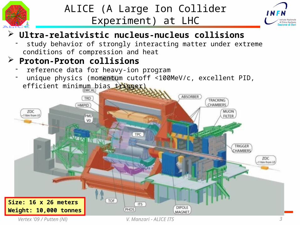
ALICE (A Large Ion Collider Experiment) at LHC
Size: 16 x 26 metersWeight: 10,000 tonnes
Ultra-relativistic nucleus-nucleus collisions- study behavior of strongly interacting matter under extreme conditions of compression and heat
Proton-Proton collisions- reference data for heavy-ion program- unique physics (momentum cutoff <100MeV/c, excellent PID, efficient minimum bias trigger)
Vertex '09 / Putten (Nl)
V. Manzari - ALICE ITS 4
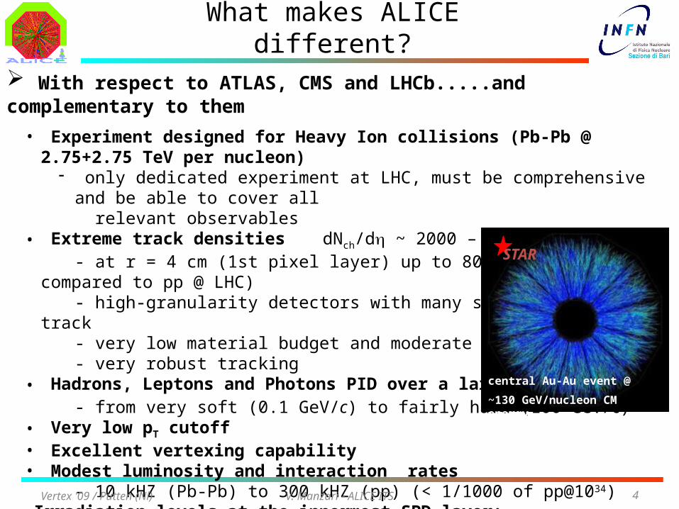
What makes ALICE different?
With respect to ATLAS, CMS and LHCb.....and complementary to them
• Experiment designed for Heavy Ion collisions (Pb-Pb @ 2.75+2.75 TeV per nucleon)- only dedicated experiment at LHC, must be comprehensive and be able to cover all
relevant observables• Extreme track densities dNch/dh ~ 2000 – 8000
- at r = 4 cm (1st pixel layer) up to 80/cm2 (x500 compared to pp @ LHC)- high-granularity detectors with many space points per track- very low material budget and moderate magnetic field- very robust tracking
• Hadrons, Leptons and Photons PID over a large pT range- from very soft (0.1 GeV/c) to fairly hard (100 GeV/c)
• Very low pT cutoff• Excellent vertexing capability• Modest luminosity and interaction rates
- 10 kHZ (Pb-Pb) to 300 kHZ (pp) (< 1/1000 of pp@1034)• Irradiation levels at the innermost SPD layer:
- 10 years standard running (108s pp + 5x10⁶s Pb-Pb + 106s Ar-Ar)TID ≈ 2.5kGy, F ≈ 3•1012 (1MeV neq)/cm2
• The price to be paid slow detectorsVertex '09 / Putten (Nl)
central Au-Au event @
~130 GeV/nucleon CM energy
STAR
V. Manzari - ALICE ITS 5
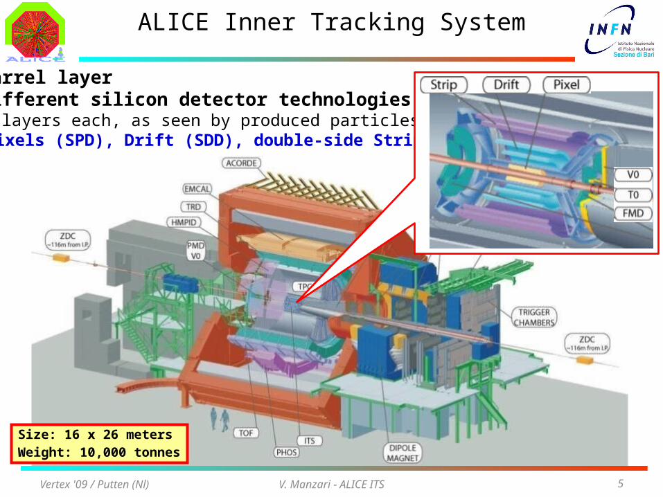
ALICE Inner Tracking System
6 barrel layer 3 different silicon detector technologies, 2 layers each, as seen by produced particles:
- Pixels (SPD), Drift (SDD), double-side Strips (SSD)
Size: 16 x 26 metersWeight: 10,000 tonnes
Vertex '09 / Putten (Nl)
V. Manzari - ALICE ITS 6
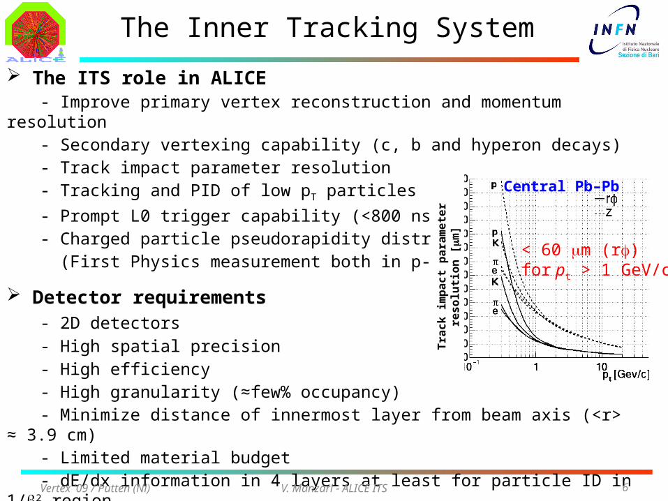
The ITS role in ALICE- Improve primary vertex reconstruction and momentum resolution- Secondary vertexing capability (c, b and hyperon decays)- Track impact parameter resolution- Tracking and PID of low pT particles
- Prompt L0 trigger capability (<800 ns)- Charged particle pseudorapidity distribution (First Physics measurement both in p-p and Pb-Pb)
Detector requirements- 2D detectors
- High spatial precision- High efficiency- High granularity (≈few% occupancy)- Minimize distance of innermost layer from beam axis (<r> ≈ 3.9 cm)- Limited material budget- dE/dx information in 4 layers at least for particle ID in 1/b2 region
The Inner Tracking System
< 60 mm (rf)for pt > 1 GeV/c
Central Pb–Pb
Tra
ck im
pac
t p
aram
eter
res
olu
tion
[m
m]
Vertex '09 / Putten (Nl)
V. Manzari - ALICE ITS 7
Detector parameters
Vertex '09 / Putten (Nl)
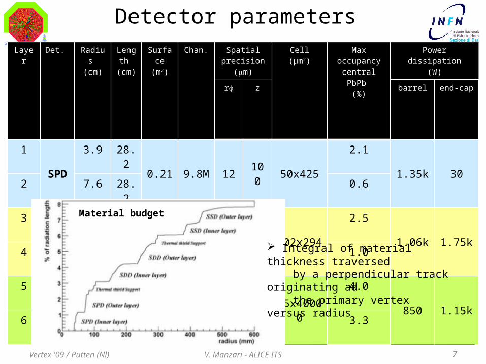
Layer Det. Radius (cm)
Length
(cm)
Surface(m2)
Chan. Spatial precision
(mm)
Cell(μm2)
Max occupancycentral PbPb
(%)
Power dissipation(W)
rf z barrel end-cap
1SPD
3.9 28.20.21 9.8M 12 100 50x425
2.11.35k 30
2 7.6 28.2 0.6
3SDD
15.0 44.41.31 133K 35 25 202x294
2.51.06k 1.75k
4 23.9 59.4 1.0
5SSD
38.0 86.25.0 2.6M 20 830 95x40000
4.0850 1.15k
6 43.0 97.8 3.3
Integral of material thickness traversed by a perpendicular track originating ad the primary vertex versus radius
Material budget
V. Manzari - ALICE ITS 8
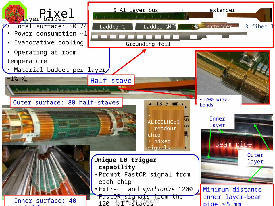
Pixel
Half-stave
Outer surface: 80 half-staves
Beam pipe
Outer layer
Inner layer
13.5 mm
15.8 mm
~1200 wire-bonds
• ALICELHCb1 readout chip• mixed signals• 8192 cells• 50x425mm2
Vertex '09 / Putten (Nl)
Unique L0 trigger capability• Prompt FastOR signal from each chip• Extract and synchronize 1200 FastOR
signals from the 120 half-staves• User defined programmable algorithms
Inner surface: 40 half-staves
Minimum distance inner layer-beam pipe 5 mm
• 2 layer barrel• Total surface: ~0.24m2
• Power consumption ~1.4kW
• Evaporative cooling C4F10
• Operating at room temperature
• Material budget per layer ~1% X0
MCM
5 Al layer bus + extender
Ladder 1 Ladder 2 MCM + extender + 3 fiber link
Grounding foil
V. Manzari - ALICE ITS 9
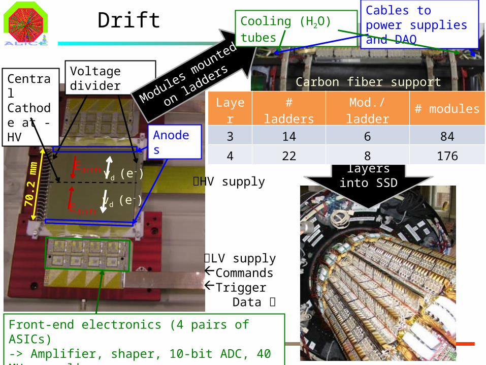
Drift
Central Cathode at -HV
Edrift
Edrift
Voltage divider
vd (e-)
vd (e-)
Anodes
HV supply
LV supplyCommandsTrigger Data
Modules mounted on
ladders Carbon fiber support
Cables to power supplies and DAQ
SDD layers into SSD
Cooling (H2O) tubes70
.2 m
m
Layer # ladders Mod./ladder # modules
3 14 6 84
4 22 8 176
Vertex '09 / Putten (Nl)
Front-end electronics (4 pairs of ASICs)-> Amplifier, shaper, 10-bit ADC, 40 MHz sampling-> Four-buffer analog memory
V. Manzari - ALICE ITS 10
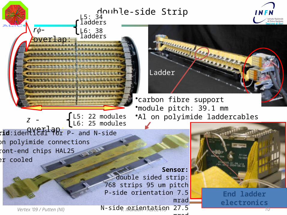
double-side Strip
r- overlap:
z - overlap:
L5: 34 laddersL6: 38 ladders
L5: 22 modulesL6: 25 modules
Ladder
End ladder electronics
Sensor:double sided strip:
768 strips 95 um pitchP-side orientation 7.5 mrad
N-side orientation 27.5 mrad
Hybrid:identical for P- and N-side
Al on polyimide connections
6 front-end chips HAL25
water cooled
•carbon fibre support•module pitch: 39.1 mm •Al on polyimide laddercables
Vertex '09 / Putten (Nl)
V. Manzari - ALICE ITS 11
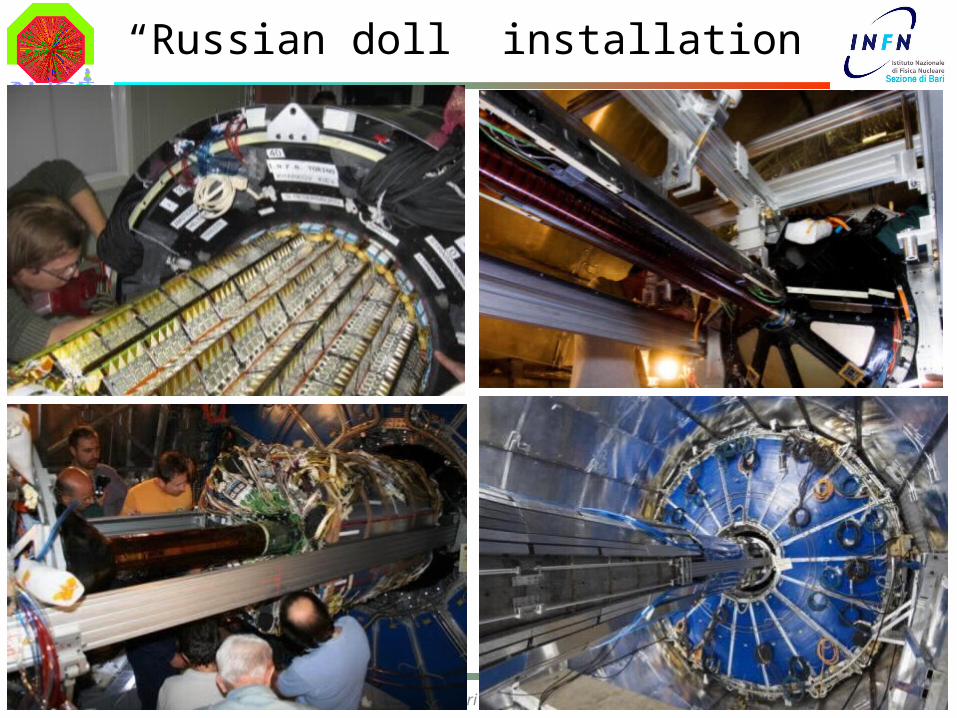
“Russian doll” installation
Vertex '09 / Putten (Nl)
V. Manzari - ALICE ITS 12
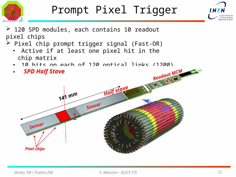
120 SPD modules, each contains 10 readout pixel chips Pixel chip prompt trigger signal (Fast-OR)• Active if at least one pixel hit in the chip matrix• 10 bits on each of 120 optical links (1200)• Transmitted every 100 ns
Prompt Pixel Trigger
Vertex '09 / Putten (Nl)
SPD Half Stave
Half stave
Sensor
Pixel chips
Readout MCM
Sensor141 mm
1
V. Manzari - ALICE ITS 13
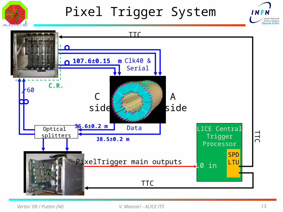
Pixel Trigger System
Optical splitters
ALICE Central Trigger
Processor
SPDLTU
Clk40 &Serial
C side
A side
Data
TTC
TTC
36.6±0.2 m
107.6±0.15 m
38.5±0.2 m
60C.R.
PixelTrigger main outputs L0 in
TT
C
Vertex '09 / Putten (Nl)
V. Manzari - ALICE ITS 14
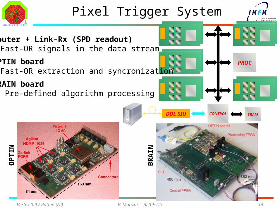
Pixel Trigger System
PROC
CONTROLDDL SIU SRAM
Router + Link-Rx (SPD readout)• Fast-OR signals in the data stream
OPTIN board• Fast-OR extraction and syncronization
BRAIN board• Pre-defined algorithm processing
OP
TIN
BR
AIN
Vertex '09 / Putten (Nl)
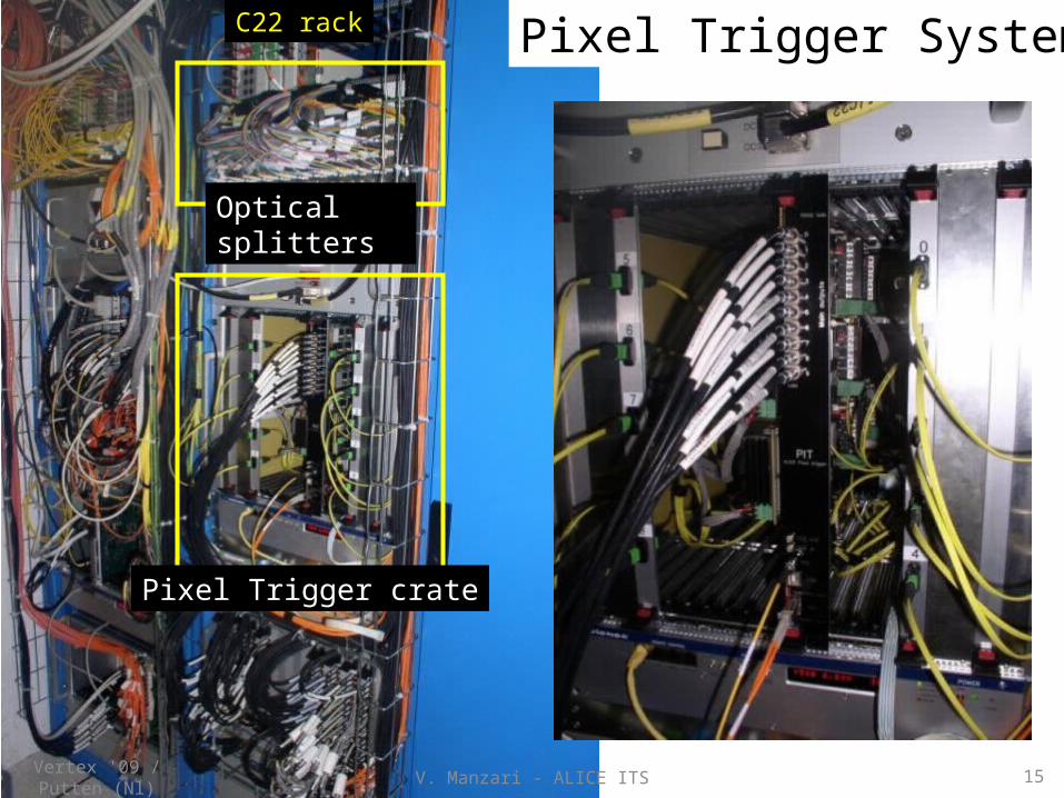
Pixel Trigger crate
Optical splitters
C22 rack Pixel Trigger System
Vertex '09 / Putten (Nl) 15V. Manzari - ALICE ITS
V. Manzari - ALICE ITS 16
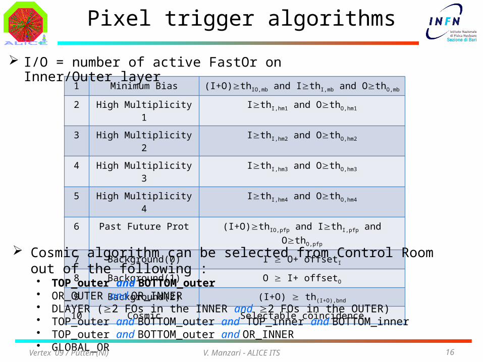
Pixel trigger algorithms
1 Minimum Bias (I+O)thIO,mb and IthI,mb and OthO,mb
2 High Multiplicity 1 IthI,hm1 and OthO,hm1
3 High Multiplicity 2 IthI,hm2 and OthO,hm2
4 High Multiplicity 3 IthI,hm3 and OthO,hm3
5 High Multiplicity 4 IthI,hm4 and OthO,hm4
6 Past Future Prot (I+O)thIO,pfp and IthI,pfp and OthO,pfp
7 Background(0) I O+ offsetI
8 Background(1) O I+ offsetO
9 Background(2) (I+O) th(I+O),bnd
10 Cosmic Selectable coincidence
I/O = number of active FastOr on Inner/Outer layer
Cosmic algorithm can be selected from Control Room out of the following :• TOP_outer and BOTTOM_outer• OR_OUTER and OR_INNER• DLAYER (2 FOs in the INNER and 2 FOs in the OUTER)• TOP_outer and BOTTOM_outer and TOP_inner and BOTTOM_inner• TOP_outer and BOTTOM_outer and OR_INNER• GLOBAL_OR
Vertex '09 / Putten (Nl)
V. Manzari - ALICE ITS 17
ITS commissioning with cosmics
Detector installation Jun ‘07• Completion of service connections Nov ’07
1st Cosmic Run Dec’07• First acquisition tests on a fraction of modules
2nd Cosmic Run Feb÷Mar ‘08
• ≈ 50 % of the ITS operable (cooling and power supply availability)• Calibration tests + first cosmic muons seen in ITS
Completion of Power Supply deployment May ‘08 3rd Cosmic Run Jun÷Oct
‘08• Subdetector specific calibration runs
– Maps of dead and noise channels, gain, drift speed, …• Cosmic runs with Pixel trigger
– First alignment of the ITS modules + test TPC/ITS track matching– Calibration of the charge signal (dE/dx) in SDD and SSDVertex '09 / Putten (Nl)
V. Manzari - ALICE ITS 18
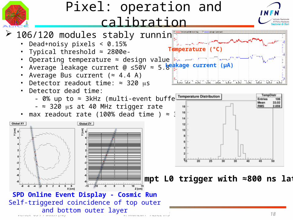
Pixel: operation and calibration 106/120 modules stably running
• Dead+noisy pixels < 0.15%• Typical threshold ≈ 2800e-• Operating temperature ≈ design value• Average leakage current @ ≤50V ≈ 5.8 µA• Average Bus current (≈ 4.4 A)• Detector readout time: ≈ 320 ms• Detector dead time:
- 0% up to ≈ 3kHz (multi-event buffering)- ≈ 320 ms at 40 MHz trigger rate
• max readout rate (100% dead time ) ≈ 3.3 kHz
Temperature (°C)
Leakage current (µA)
Vertex '09 / Putten (Nl)
Prompt L0 trigger with ≈800 ns latency
SPD Online Event Display - Cosmic RunSelf-triggered coincidence of top outer and bottom outer layer
V. Manzari - ALICE ITS
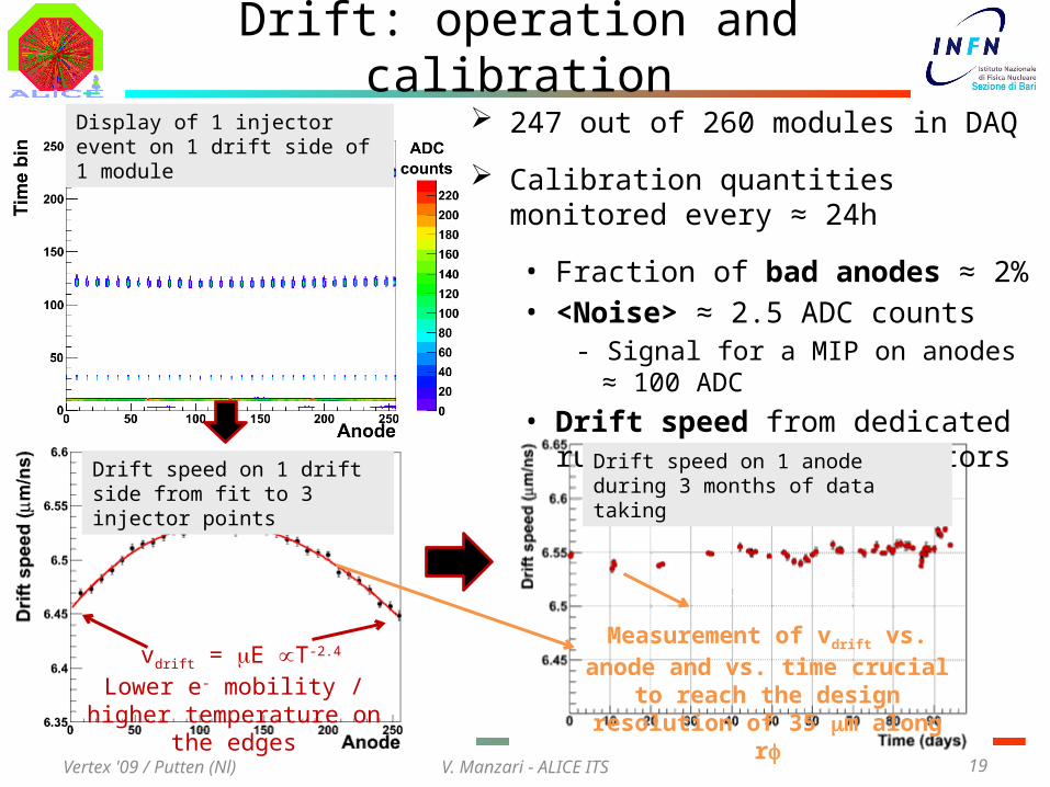
Drift: operation and calibration 247 out of 260 modules in DAQ
Calibration quantities monitored every ≈ 24h
• Fraction of bad anodes ≈ 2%• <Noise> ≈ 2.5 ADC counts
- Signal for a MIP on anodes ≈ 100 ADC
• Drift speed from dedicated runs with charge injectors
19
Display of 1 injector event on 1 drift side of 1 module
Drift speed on 1 drift side from fit to 3 injector points
vdrift = mE T-2.4
Lower e- mobility / higher temperature on the edges
Drift speed on 1 anode during 3 months of data taking
Measurement of vdrift vs. anode and vs. time crucial to reach the design
resolution of 35 mm along rf
Vertex '09 / Putten (Nl)
V. Manzari - ALICE ITS 20
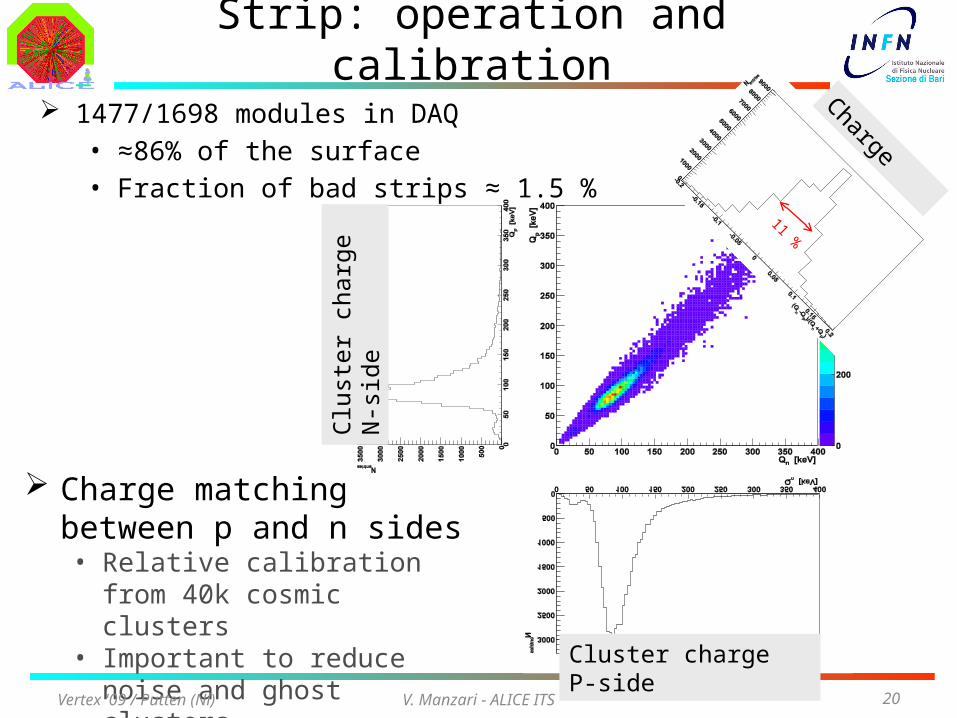
Charge ‘ratio’
Clu
ster
cha
rge
N-s
ide
Cluster charge P-side
Strip: operation and calibration
1477/1698 modules in DAQ• ≈86% of the surface • Fraction of bad strips ≈ 1.5 %
11 %
Charge matching between p and n sides• Relative calibration from 40k
cosmic clusters• Important to reduce noise and
ghost clusters
Vertex '09 / Putten (Nl)
V. Manzari - ALICE ITS 21
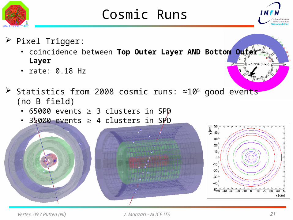
Cosmic Runs
Pixel Trigger:• coincidence between Top Outer Layer AND Bottom Outer Layer• rate: 0.18 Hz
Statistics from 2008 cosmic runs: ≈105 good events (no B field)• 65000 events 3 clusters in SPD• 35000 events 4 clusters in SPD
Vertex '09 / Putten (Nl)
V. Manzari - ALICE ITS 22
Alignment methods
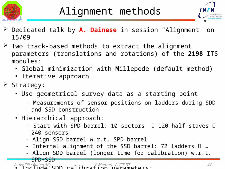
Dedicated talk by A. Dainese in session “Alignment” on 15/09 Two track-based methods to extract the alignment parameters (translations and
rotations) of the 2198 ITS modules:• Global minimization with Millepede (default method)• Iterative approach
Strategy:• Use geometrical survey data as a starting point
- Measurements of sensor positions on ladders during SDD and SSD construction
• Hierarchical approach:- Start with SPD barrel: 10 sectors 120 half staves 240 sensors - Align SSD barrel w.r.t. SPD barrel- Internal alignment of the SSD barrel: 72 ladders …- Align SDD barrel (longer time for calibration) w.r.t. SPD+SSD
• Include SDD calibration parameters:
- Non-constant drift field due to non-linear voltage divider
- Parasitic electric fields due to inhomogeneities in dopant concentration
Vertex '09 / Putten (Nl)
V. Manzari - ALICE ITS 23
Alignment with cosmics
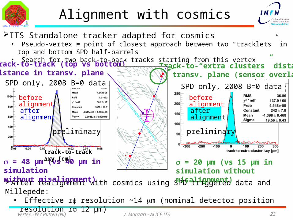
After realignment with cosmics using SPD triggered data and Millepede:• Effective rf resolution ~14 mm (nominal detector position resolution r 12 µm)
= 20 μm (vs 15 μm in simulation without misalignment)
Vertex '09 / Putten (Nl)
ITS Standalone tracker adapted for cosmics• Pseudo-vertex = point of closest approach between two “tracklets” in top and bottom SPD half-barrels• Search for two back-to-back tracks starting from this vertex
Track-to-track (top vs bottom) distance in transv. plane
= 48 μm (vs 40 μm in simulation without misalignment)
Track-to-“extra clusters” distance in transv. plane (sensor overlap)
after alignment
before alignment
after alignment
before alignment
SPD only, 2008 B=0 data SPD only, 2008 B=0 data
preliminary preliminary
track-to-track Dxy [cm]
V. Manzari - ALICE ITS 24
Drift: calibration
Vertex '09 / Putten (Nl)
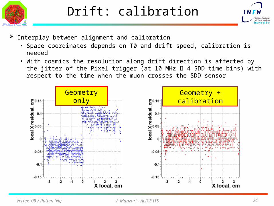
Interplay between alignment and calibration• Space coordinates depends on T0 and drift speed, calibration is needed• With cosmics the resolution along drift direction is affected by the jitter of
the Pixel trigger (at 10 MHz 4 SDD time bins) with respect to the time when the muon crosses the SDD sensor
Geometry only Geometry + calibration
V. Manzari - ALICE ITS 25
Strip and Drift: energy loss
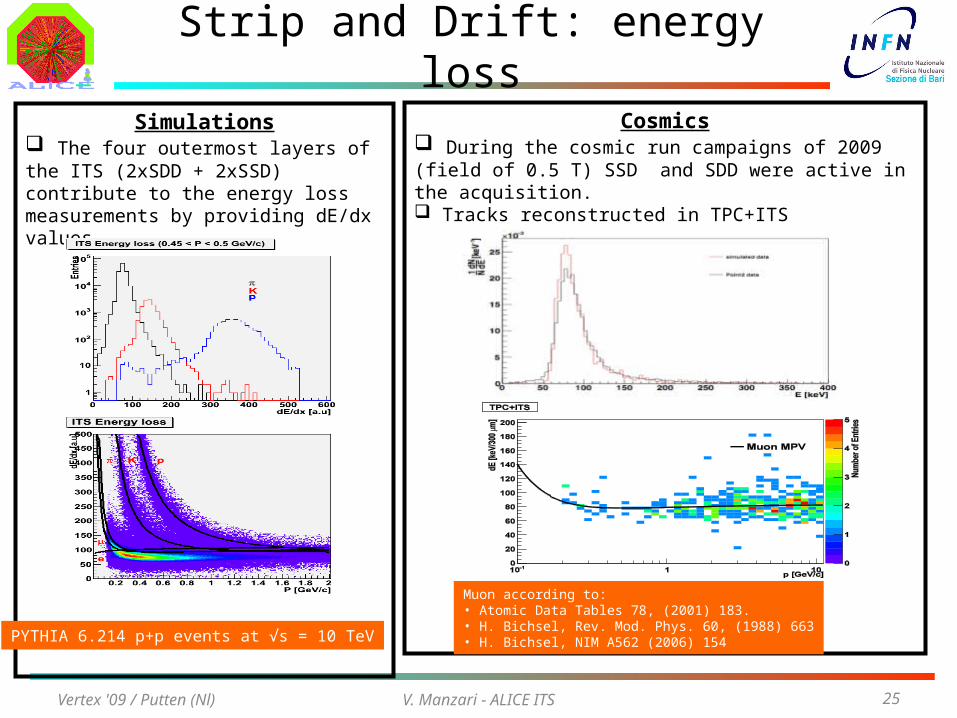
Simulations The four outermost layers of the ITS (2xSDD + 2xSSD) contribute to the energy loss measurements by providing dE/dx values.
PYTHIA 6.214 p+p events at √s = 10 TeV
Cosmics During the cosmic run campaigns of 2009 (field of 0.5 T) SSD and SDD were active in the acquisition. Tracks reconstructed in TPC+ITS
Muon according to:• Atomic Data Tables 78, (2001) 183.• H. Bichsel, Rev. Mod. Phys. 60, (1988) 663• H. Bichsel, NIM A562 (2006) 154
Vertex '09 / Putten (Nl)
V. Manzari - ALICE ITS 26
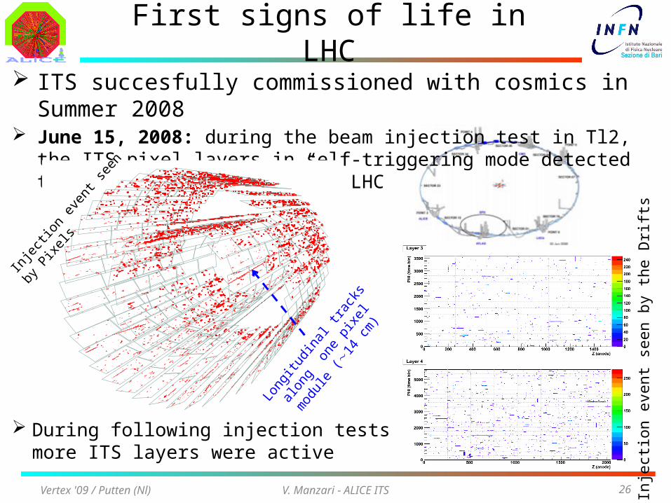
First signs of life in LHC ITS succesfully commissioned with cosmics in Summer 2008 June 15, 2008: during the beam injection test in Tl2, the ITS pixel layers in self-
triggering mode detected the first “sign of life” of LHC
Vertex '09 / Putten (Nl)
Longi
tudi
nal t
rack
s alo
ng o
ne
pixe
l mod
ule (1
4 cm
)
During following injection tests more ITS layers were active
Inje
ctio
n ev
ent s
een
by th
e D
rift
s
Injec
tion
even
t see
n by
Pix
els
V. Manzari - ALICE ITS 27
Beam induced background
Vertex '09 / Putten (Nl)
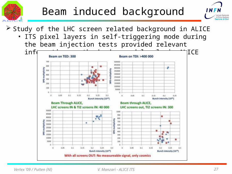
Study of the LHC screen related background in ALICE• ITS pixel layers in self-triggering mode during the beam injection tests
provided relevant information on the background levels in ALICE
V. Manzari - ALICE ITS 28
First collision
Vertex '09 / Putten (Nl)
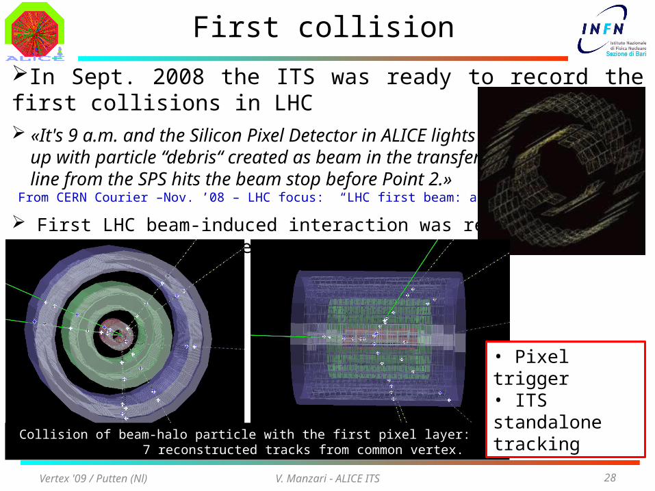
In Sept. 2008 the ITS was ready to record the first collisions in LHC «It's 9 a.m. and the Silicon Pixel Detector in ALICE lights up with particle “debris“ created as beam in the transfer line from the SPS hits the beam stop before Point 2.» From CERN Courier –Nov. ’08 – LHC focus: “LHC first beam: a day to remember”
First LHC beam-induced interaction was recorded by the ALICE ITS on 11 Sep ’08
Collision of beam-halo particle with the first pixel layer: 7 reconstructed tracks from common vertex.
• Pixel trigger• ITS standalone tracking
V. Manzari - ALICE ITS 29
ALICE and ITS in 2009
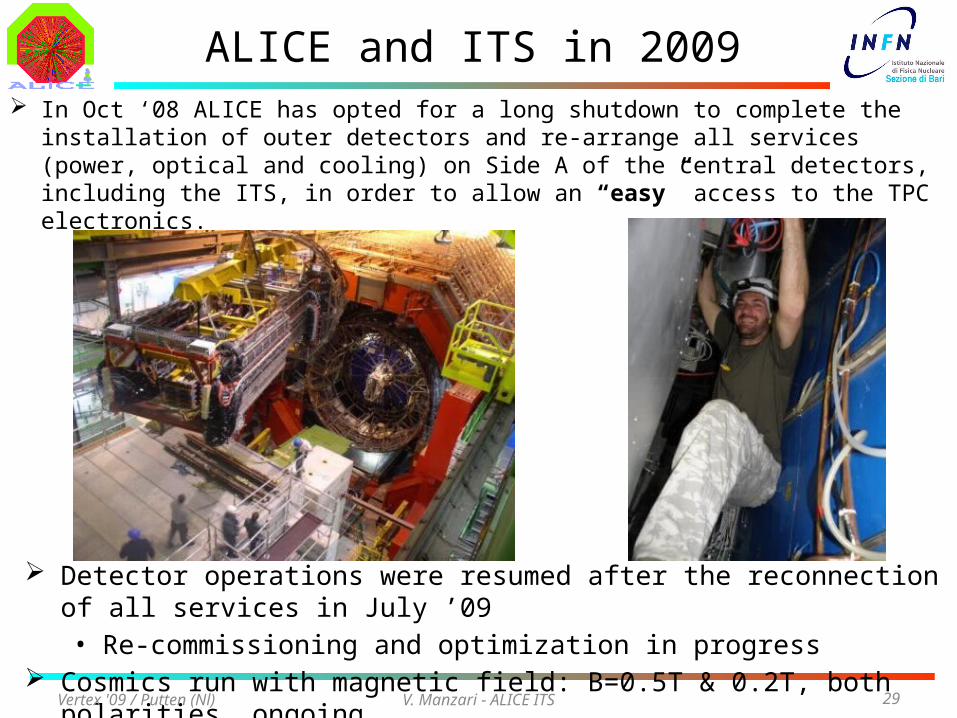
Detector operations were resumed after the reconnection of all services in July ’09• Re-commissioning and optimization in progress
Cosmics run with magnetic field: B=0.5T & 0.2T, both polarities, ongoing
Vertex '09 / Putten (Nl)
In Oct ‘08 ALICE has opted for a long shutdown to complete the installation of outer detectors and re-arrange all services (power, optical and cooling) on Side A of the central detectors, including the ITS, in order to allow an “easy” access to the TPC electronics.
V. Manzari - ALICE ITS 30
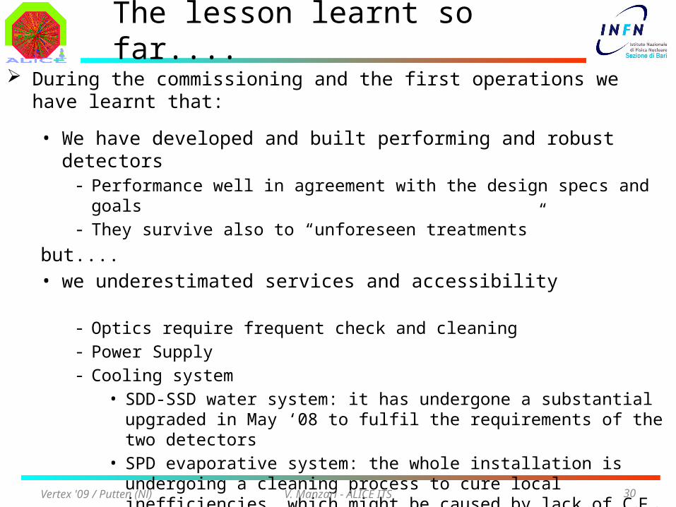
The lesson learnt so far.... During the commissioning and the first operations we have learnt that:
• We have developed and built performing and robust detectors- Performance well in agreement with the design specs and goals- They survive also to “unforeseen treatments”
but....• we underestimated services and accessibility
- Optics require frequent check and cleaning- Power Supply- Cooling system
• SDD-SSD water system: it has undergone a substantial upgraded in May ‘08 to fulfil the requirements of the two detectors
• SPD evaporative system: the whole installation is undergoing a cleaning process to cure local inefficiencies which might be caused by lack of C4F10 flow.
- Air conditions in the innermost detector volume• Control and monitoring of temperature and humidity
Vertex '09 / Putten (Nl)
V. Manzari - ALICE ITS 31
Conclusions
The ALICE Inner Tracking System was successfully commissioned with cosmics during summer 2008 and was ready for the first collisions in September
• Integration and operating stability with ALICE central services (ECS, DAQ, CTP and DCS), Alignment studies and Calibration runs were performed over several months of data taking
Alignment is very well advanced
• Collected statistics of cosmic tracks allowed for:
- Most of SPD modules alignement to 8 mm; 50% of SSD modules (the
ones close to the vertical with higher statistics) also aligned. SDD on the way
- dE/dx signal calibration in SDD and SSD
Cosmic runs with different magnetic fields are ongoing
Final optimization of the detector performance is well advanced• Activities tuned with the LHC schedule
Vertex '09 / Putten (Nl)
V. Manzari - ALICE ITS 32
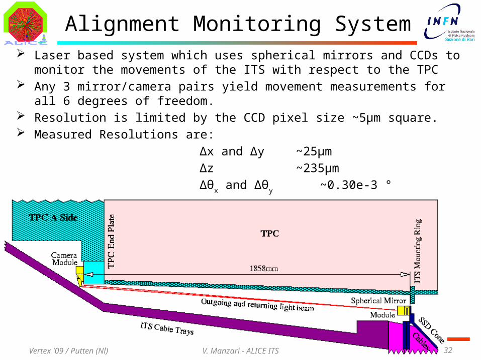
Alignment Monitoring System Laser based system which uses spherical mirrors and CCDs to monitor the movements of
the ITS with respect to the TPC Any 3 mirror/camera pairs yield movement measurements for all 6 degrees of freedom. Resolution is limited by the CCD pixel size ~5μm square. Measured Resolutions are:
Δx and Δy~25μm
Δz~235μm
Δθx and Δθ
y
~0.30e-3 °Δθ
z
~1.75e-3 °
Vertex '09 / Putten (Nl)