Embed Size (px)
Citation preview

The Airbus Safety Magazine
SafetyEdition July 2012
Issue 14
Contents:q Thrust Reverser Selection
Means Full-Stop
q Transient Loss of Communication due to Jammed Push-To-Talk A320 and A330/A340 Families
q A380: Development of the Flight Controls - Part 2
q Preventing Fan Cowl Door Loss
q Do not forget that you are not alone in Maintenance

Safety FirstThe Airbus Safety Magazine
For the enhancement of safe flight through
increased knowledge and communications
Safety First is published by the Flight Safety Department of Air-bus. It is a source of specialist safe-ty information for the restricted use of flight and ground crew members who fly and maintain Airbus air-craft. It is also distributed to other selected organisations.
Material for publication is obtained from multiple sources and includes selected informa-tion from the Airbus Flight Safety Confidential Reporting System, incident and accident investiga-tion reports, system tests and flight tests. Material is also ob-tained from sources within the airline industry, studies and re-ports from government agencies and other aviation sources.
All articles in Safety First are present-ed for information only and are not intended to replace ICAO guidelines, standards or recommended practices, operator-mandated requirements or technical orders. The contents do not supersede any requirements mand ated by the State of Registry of the Opera-tor’s aircraft or supersede or amend any Airbus type-specific AFM, AMM, FCOM, MEL documentation or any other approved documentation.
Articles may be reprinted without permission, except where copy-right source is indicated, but with acknowledgement to Airbus. Where Airbus is not the author, the con-tents of the article do not necessarily reflect the views of Airbus, neither do they indicate Company policy.
Contributions, comment and feed-back are welcome. For technical reasons the editors may be required to make editorial changes to manu-scripts, however every effort will be made to preserve the intended meaning of the original. Enquiries related to this publication should be addressed to:
AirbusProduct Safety department (GS)1, rond point Maurice Bellonte31707 Blagnac Cedex - FranceContact: Nils FAYAUDE-mail: [email protected]: +33(0)5 61 93 44 29
Safety First, #14 June 2012. Safety First is published by Airbus S.A.S. - 1, rond point Maurice Bellonte - 31707 Blagnac Cedex/France. Editor: Yannick Malinge, Chief Product Safety Officer, Nils Fayaud, Director Product Safety Information. Concept Design by Airbus Multi Media Support Ref. 20121045. Computer Graphic by Quat’coul, Fixion, Abac Effect. Copyright: GS 420.0029 Issue 14. Photos copyright Airbus. Photos by Pascal Chenu, ExM Company: P. Masclet. Printed in France by Airbus Print Centre.
© Airbus S.A.S. 2012 – All rights reserved. Proprietary documents.
By taking delivery of this Brochure (hereafter “Brochure”), you accept on behalf of your company to
comply with the following guidelines:
3 No other intellectual property rights are granted by the delivery of this Brochure than the right to read
it, for the sole purpose of information.
3 This Brochure and its content shall not be modified and its illustrations and photos shall not be repro-
duced without prior written consent of Airbus.
3 This Brochure and the materials it contains shall not, in whole or in part, be sold, rented, or licensed
to any third party subject to payment.
This Brochure contains sensitive information that is correct at the time of going to press.
This information involves a number of factors that could change over time, effecting the true public
representation. Airbus assumes no obligation to update any information contained in this document or
with respect to the information described herein.
Airbus S.A.S. shall assume no liability for any damage in connection with the use of this Brochure and
of the materials it contains, even if Airbus S.A.S. has been advised of the likelihood of such damages.
The Airbus Safety Magazine
SafetyEdition July 2012
Issue 14
CONTENT:q Thrust Reverser Selection
Means Full-Stop
q Transient Loss of Communication due to Jammed Push-To-Talk A320 Family and A330/A340
q A380: Development of the Flight Controls - Part 2
q Preventing Fan Cowl Door Loss
q Do not forget that you are not alone in Maintenance
A400M Formation of five A400M nose to tail at Toulouse-Blagnac Airport
2 Issue 14 | JuLY 2012 Safety

Editorial
ContentsSince our January 2012 issue of this magazine, we held our 18th Annual Safety Conference in March. This took place in Berlin and was attended by more airlines and more delegates that any previous conference. Bearing in mind the general financial situation in our industry at the moment, this provided a pleasing confirmation of our jointly held strong commitment to Safety.
One of the main themes of the conference was Culture. This was examined in both a managerial sense, where the clear commitment of the most senior managers is so vital to support Safety thinking down through all levels within an airline, and also in the Operational area where it is key to getting the best out of the team directly involved with the task.
We also majored on Training. By taking a look at what is trained today and what will be needed tomorrow, we all recognize the need to “close the gap” in this regard. Much good work is being done through the indus-try Evidenced Based Training initiative. As in-service events hopefully become fewer in number with improved reliability, quality and overall safety, then by definition pilots will experience these events less fre-quently. Whilst this is of course good, it does mean that pilots will have less and less opportunities to keep their knowledge and skills “sharp”. Indeed, opportunities to maintain “stick and rudder” skills are becoming more and more rare, which is further aggravated by the evolution of the Air Transport System where opportunities for manual fly-ing are decreasing. How we deal with this issue is just one of the chal-lenges we all face.
There is no doubt that this debate is on-going across the whole air transport industry.
In the mean time, you will find in this issue the follow-up of our series of articles on the development of the A380 flight controls, as well as two recurrent topics that deserve a regular reminder in terms of adherence to procedures: fan cowl door loss and use of engine thrust reversers.
Enjoy your reading !
Yannick MALINGE Chief Product Safety Officer
The Airbus Safety Magazine
Information ..................................................4
Thrust Reverser Selection Means Full-Stop ............................................5 Xavier Barriola
Transient Loss of Communication due to Jammed Push-To-Talk A320 and A330/A340 Families ...................................... 8Benoît DUVAL
A380: Development of the Flight Controls - Part 2 ......................... 12CLAUDe LeLAIe
Preventing Fan Cowl Door Loss ................ 16Xavier JOLIVeT / Stéphane RAMON
Do not forget that you ................................ 20 are not alone in MaintenanceUwe eGGeRLING
Yannick MALINGE Chief Product Safety Officer
3Issue 14 | JULY 2012The Airbus Safety Magazine
Magazine distribution
If you wish to subscribe to Safety First, please fill out the subscrip-tion form that you will find at the end of this issue.
Please note that the paper copies will only be forwarded to profes-sional addresses.
Your articles
As already said, this magazine is a tool to help share information.
We would appreciate articles from operators, that we can pass to other operators through the magazine.
If you have any inputs then please contact Nils Fayaud at:
e-mail: [email protected] fax : +33 (0) 5 61 93 44 29
The Flight Safety Conference provides an excellent forum for the exchange of information between Airbus and its custo-mers. To ensure that we can have an open dialogue to promote flight safety across the fleet, we are unable to accept outside parties.
We are pleased to announce that the 19th Flight Safety Conference will take place in Bangkok, Thailand, from the 18th to the 21st of March 2013. The formal invitations with information regarding registration and logistics, as well as the preliminary agenda will be sent to our customers in December 2012.
For any information regarding invitations, please contact Mrs. Nuria Soler, email [email protected]
As always, we welcome presentations from our operators. You can participate as a speaker and share your ideas and expe-rience for improving aviation safety.
If you have something you believe will benefit other operators and/or Airbus and if you are interested in being a speaker, please provide us with a brief abstract and a bio or resume at [email protected]
Safety Information on the Airbus websites
On the AirbusWorld website we are building up more safety information for you to use.
The present and previous issues of Safety First can be accessed to in the Flight Operations Community- Safe-ty and Operational Materials portal-, at https://w3.airbusworld.com
Other safety and operational exper-tise publications, like the Getting to Grips with…brochures, e-briefings etc…are regularly released as well in the Flight Operations Commu-nity at the above site.
If you do not yet have access rights, please contact your IT administrator.
Information
SAVE THE DATE19th
Bangkok, 18-21 March 2013
Flight Safety Hotline: +33 (0)6 29 80 86 66e-mail: [email protected]
Nils FAYAudDirector Product Safety Information
News
4 Issue 14 | JULY 2012 Safety

Xavier Barriola Flight Safety
Thrust Reverser Selection Means Full-Stop1. IntroductionWhen full forward thrust (TOGA) is applied after thrust reverser se-lection, there is a risk of non avail-ability of maximum thrust on one or more engines, if the associated reversers do not stow.
This is exactly what happened to an A300-600 equipped with PW4158 engines, which carried out an aborted landing whilst the thrust reversers were still in transit and not fully deployed. As a result of a failure of the electrical restow circuit, the aborted landing was performed with only one engine delivering take-off thrust.
This article will describe the event and review operational recommen-dations on throttle handling.
This event illustrates the necessity to strictly follow the rule specified in the FCOM: “After reverse thrust is initiated, a full-stop landing must be performed.” This statement is valid for all Airbus aircraft types.
2. Event description and Analysis2.1 ApproachThe Captain was the pilot flying. The autopilot was not engaged and the approach speed (Vapp) was 143kt. The weather report indicated rain and cross wind conditions (160°, 20kt gusting at 30kt). The flare was performed at 30ft Above Ground Level (AGL).
160°/20ktGusting at 30kt
2.2 TouchdownThe A300-600 touched down with an Indicated Air Speed (IAS) of 138kt and landed hard with a ver-tical acceleration of 1.82g.
At touchdown the pilot immediately selected the thrust reverser levers to max reverse and the reversers started to deploy (refer to note 1).
The aircraft bounced, and conse-quently the Captain decided to abort the landing while the thrust rever-sers were still in transit and there-fore not fully deployed.
note 1The purpose of the thrust reverser system is to direct fan air forward, to produce reverse thrust and thus to reduce aircraft speed during landing rollout.
“Stowed” is the normal flight position.
“Deployed” is selected after touchdown, producing a forward angled airflow path as engine power is increased. This redirected airflow creates a rearward or reverse thrust effect that is used to slow the aircraft during landing rollout.The amount of reverse thrust is varied by thrust reverser control lever movement.
0 9
5Issue 14 | JULY 2012The Airbus Safety Magazine

note 3Reverse stowed and latched (ReV UNLK light OFF) means that it is stowed within 0.125 inch of the full stow stop. At this point, the movement of the thrust reverser sleeve can only be due to vibration, aerodynamic loads (external and in the fan duct), or airplane maneuvers.
Consequently temporary intermittent unlocked indication could be considered to be due to vibration during final transit of the translating sleeve to the full stow stop position.
note 4The thrust reverser lights indicate the operational status of the thrust reverser systems. When all lights are OFF, the translating sleeves are in the stowed position, the systems are latched.
note 2A defective pin at connector level (junction box D5010P) was at the origin of the electrical restow circuit failure.
Jonction Box Connector D50010P
REV REV UNLK REV UNLK REVGPWS
LANDINGSLATS/FLAPS
15/20
30/40
00.0
12.356
L STAT
R STAT
L STAT
R STAT
FIRE
432VU
435VU
437VU
431VU
438VU
DISCHAGENT 2
SMOKESMOKE
SYSACTUATED
G
O
C
O
C
LP
REV UNLK LIGHTSA light comes on amber when:- The related thrust reverser system is unlatched,- The translating sleeves travel between the status position and 90% of their travel.
REV LIGHTSA light comes on green when the translating sleeves of the related thrust reverser system are beyond 90% of their travel.
2.3 Aborted Landing
While the thrust reversers were still in transit to deploy and the amber REV UNLK lights were ON, they were selected to be stowed, then TOGA was applied on both engines.
On engine 1, the thrust reverser stowed and consequently the FADEC 1 commanded engine 1 at TOGA.
On engine 2, the thrust reverser did not stow and stayed half open due to failure of the electrical restow circuit (refer to note 2).
Consequently, as per design with reverser not stowed, the Auto Idle function of FADEC 2 command-ed engine 2 to Idle thrust. A tail strike was experienced during ro-tation.The liftoff was performed in conf 30/40 (FULL), with an IAS of 125kt .
During liftoff, temporary and intermittent ENG1 REV UNLK (refer to note 3) and permanent ENG2 REV UNLK lights were ON (refer to note 4).
2.4 diversion
Once airborne, the pilot put the engine 2 thrust lever into the Idle position, then cycled the reverser lever to stow the reverser. The engine 2 thrust reverser remained in the partially deployed position (half open) because:
q The electrical failure of the restow circuit prevented the re-verser from stowing correctly
q A design protection prevents reverser movement in flight.
The pilot then advanced the engine 2 thrust lever to check for thrust response, but the thrust did not increase due to the FADEC’s Auto Idle function.
The pilot then shut down engine 2 and diverted to an alternate airport where a single engine landing was performed with engine 1 thrust reverser selected.
6 Issue 14 | JULY 2012 Safety

ENG REV UNLKTHROTTLe (affected engine) ...................................... IDLeDIVeRSION ........................................................CONSIDeRMAX SPD ..................................................................... 300• IF BUFFET OR BANK:
FUeL LeVeR ............................................................ OFFMAX SPD ..................................................................240PROC: SINGLe eNG OPeRATION (12.08)................APPLY
eNG AT IDLeDisplayed only if engine is automatically set at idle by FADeC
3. Operational Recommendations3.1 Throttle Handling in FlightAccording to the A300-600 FCOM 2.05.70 (ENG REV UNLK procedure), the throttle of the affected engine has to be put and left in the Idle position. No movement of the thrust and re-verser levers is authorized while the engine is ON.
3.2 Throttle Handling during Aborted Landing / Touch and Goa) The A300-600 FCOM 2.03.22 (At TOUCHDOWN) mentions:
q After reverse thrust is initi-ated, a full-stop landing must be performed.
This statement is valid for all Airbus aircraft types, and is also mentioned in the associ-ated FCOM (Normal Procedure – SOP – Landing).
q Do not move reverse levers towards stow position while re-verser are in transit; such action may cause system damage.
b) The A300-600 FCOM 2.02.01 (BOUNCING AT LANDING) has been updated in June 2012 with the following additional statement:
“In any case, if reverse thrust has been selected, a full stop landing must be performed.”
The FCOM of the other Airbus aircraft types will be updated accordingly in the next revi-sions.
4. ConclusionAs a result of the crew’s decision to abort the landing after they had selected reverse thrust, the aircraft took off with one engine on Idle and the aircraft’s tail impacted the runway.
This occurrence illustrates that when TOGA is applied after thrust reverser selection, there is a risk of non avail-ability of maximum thrust on one or more engines if the associated re-versers do not stow. This protection is triggered by the Auto Idle function of the FADEC, which maintains the engine thrust at Idle as long as the reversers are not stowed. The conse-quence could be a loss of control if an aborted landing is initiated at that time.
We therefore strongly encourage all crews to adhere to the following FCOM recommendation, which is common to all Airbus aircraft types:
“After reverse thrust is initiated, a full-stop landing must be per-formed.”
A previous article published in the first issue of this magazine: “A320 In-Flight Thrust Reverser Deploy-ment”, dated Jan 2005, describes an event where a takeoff was carried despite a REV UNLK warning.
The common key message from these two articles is that it is essential to strictly adhere to any procedure associated with the operation of thrust reversers.
AT TOUCHDOWNREVERSE LEVERS . . . . . . . . . . . . . . . . . . . Pull- Immediately after touch-down of main landing gear, pull
reverse levers to the idle reverse point, when REV (green) appears, apply max reverse.
- After reverse thrust is initiated, a full-stop landing must be performed.
Note 1: Maximum efficiency of the reverse is obtained at high speed
Note 2: Do not move reverse levers towards stow posi-tion while reversers are in transit; such action may cause system damage.
Note 3: If one or both REV UNLK lt remains on, apply reverse normally.
Note 4: If the use of max reverse is restricted due to noise consideration, maintain reverse idle until taxi speed is reached.
Note 5: If directional control problems are encountered, re-duce thrust to reverse idle until directional control is satisfactory.
- MAX. REVERSE THRUST . . . . . . . . . . . . . . . Apply- N1, EGT and IAS . . . . . . . . . . . . . . . . . . . . . .Monitor
BOUNCING AT LANDINGIn case of light bounce (5 ft or less), maintain pitch attitude and complete the landing. Do not increase pitch attitude, as this could lead to a tailstrike.In case of a high bounce (more than 5 ft) maintain pitch attitude and configuration, and initiate a go-around by ad-vancing throttle levers while triggering the go-levers. This will soften the second touchdown that will most probably occur and prevent damage to the aircraft.Retract flaps one step and landing gear only when safely established in the go-around and no risk of further touch-down exists.A landing should not be attempted after a high bounce, as the remaining runway length might not be enough to stop the aircraft. In any case, if reverse thrust has been selected, a full stop landing must be performed.
7Issue 14 | JULY 2012The Airbus Safety Magazine

In the normal configuration, three ACP are available. They are lo-cated on the Captain side (ACP1), on the F/O side (ACP2), and on the overhead panel (ACP3). The ACP3 allows reconfiguration in case of failure of ACP1 or ACP2.
Initially, the pilot has to press one of the ACP transmission keys in order to select a VHF or HF trans-ceiver. Then, in order to actually transmit on the selected radio, he uses one of the Push-To-Talk
Benoît duVALSafety enhancement ManagerAircraft Architecture and Integration
Transient Loss of Communication due to Jammed Push-To-Talk A320 and A330/A340 Families
2. Transmitting with VHF or HFIn order to transmit on VHF or HF radio, the flight crew uses one of the Audio Control Panels (ACP) (fig.1).
1. IntroductionAt the end of 2011, the crew of a cruising A320 was unable to transmit on any radio, but reported that it was still possible to receive ATC com-munications. A few months before, on another A320, the crew reported after landing that it was not possible to contact the tower via either VHF system. Investigations attributed both events to Push-To-Talk (PTT) selec-tors jammed in the transmit position.
As illustrated by these examples, jammed PTT selectors generate events of transient loss of commu-nication with ATC every year.
This kind of failure might be dif-ficult to identify for the crew, and might lead to the feeling that all communications have been lost with ATC. In reality, a correct iden-tification of the situation and the im-plementation of a few simple steps will, in most cases, allow the crew to recover full communications.
This article will outline the effects of a jammed PTT and will explain how to restore communications. It will also describe a new ECAM caution and procedure that will be introduced in the next Flight Warning Computer (FWC) standards.
2ADF12VOR1
RESET
PA2SAT1
MKR
ILS
INT
RAD
VOICE
CABINTHF2HF1VHF3VHF2VHF1
CALLCALL
ATTMECHCALLCALLCALLCALLCALL
SELCAL CALL
TRANSMISSION KEYS
RECEPTION KNOBS
PASSENGER ADDRESS FUNCTION
SELCAL/CALL RESET KEY
RECEPTION KNOBS
VOICE FILTER
INT/RAD SWITCH
Figure 1Audio Control Panel
(ACP)
devices: side stick radio selec-tor, hand mike PTT, or INT/RAD switch on the ACP (fig.2).
3. Impacts of a Jammed Push-To-Talk3.1 VHFWhen a Push-To-Talk device is jammed in the transmit position, the VHF transceiver transmits continuously as soon as it is se-lected, and no reception is possi-ble on the tuned frequency.
In order to limit such a continuous and unintentional transmission
8 Issue 14 | JULY 2012 Safety

Figure 2Push-To-Talk
devices
Figure 3Audio Switching
rotary switch
INT
RAD
NEUTRAL
RAdio
Side Stick radio Selector
Hand Mike
INT/RAD switch on Audio Control Panel
that could disturb the ATC fre-quency, an internal protection is implemented inside each VHF, limiting the transmission time to 35s. After 30s of transmis-sion, the crew is warned of this imminent automatic transmis-sion cut-off through an inter-rupted tone that sounds for 5 seconds (5 audio “beeps”, one per second).
In normal operation, on hearing the 5 audio “beeps” the crew has to release and press again the PTT selector/button to continue the transmission. But if the Push-To-Talk device is jammed the trans-mission may not be resumed on the selected radio, which will be limited to reception only. In this case, an ECAM COM VHF (1 or 2 or 3) EMITTING caution is also triggered after 60s.
3.2 HFThere is no automatic transmis-sion cut-off after 35s on the HF transceivers, but an ECAM COM HF (1 or 2) EMITTING caution is triggered as well if the HF transmission duration exceeds 60s.
4. VHF/HF Communication Recovery In Case of a Jammed Push-To-Talk4.1 Typical scenarioConsider, for example, an attempt of VHF1 communication with a side-stick PTT jammed on the Capt side. As soon as the VHF1 transmission key is selected on the Audio Control Panel located on the Capt side (ACP1), a continuous VHF1 transmission is initiated.
The VHF1 transmission will be automatically interrupted after 35s (VHF internal protection). 25s later, the Flight Warning System (FWS) will trigger the ECAM COM VHF1 EMITTING caution.
If the crew tries to select another VHF on the same ACP, for example VHF2, the same scenario will occur as the side-stick PTT is still jammed: the VHF2 will be automatically in-terrupted after 35s and the COM VHF2 EMITTING alert will trigger 25s later.
Selection of “CAPT ON 3” by means of the Audio Switching rotary switch (fig. 3), to use the ACP3 (over-head panel) on the Captain side, will not solve the problem as the jammed PTT will request a permanent trans-mission through the ACP3.
CAPTON 3
F/OON 3
AUDIONORM
4.2 RecoveryThe way to handle the situation in this case, is to first check the PTT transmission selector and try to release it. Then, if this does not work, isolate the jammed PTT and the associated Audio Control Panel by deselecting all the VHF transmission keys on the ACP1. It is then possible to use the ACP2 and the associated PTT devices, on the F/O side, to establish a new VHF transmission.
Such a procedure is available to-day in the FCOM, as expanded information associated to the COM VHF/HF EMITTING cau-tion (fig.4 & 5).
Figure 5A330/A340 FCOM information associated to the COM VHF/HF EMITTING caution
Figure 4A320 Family FCOM information associated to the COM VHF/HF EMITTING caution
Figure 4 – FCOM Volume 3 – Abnormal and Emergency (3.02.23)
Transient Loss of Com due to jammed PTT - Draft 04
Single Aisle Family
© AIRBUS Operations S.A.S. Tous droits réservés. Document confidentiel.
A330/A340
Figure 4 – FCOM Volume 3 – Abnormal and Emergency (3.02.23)
Transient Loss of Com due to jammed PTT - Draft 04
Single Aisle Family
© AIRBUS Operations S.A.S. Tous droits réservés. Document confidentiel.
A330/A340
9Issue 14 | JULY 2012The Airbus Safety Magazine

5. New ECAM Caution and Procedure in Case of a Jammed Push-To-Talk5.1 VHFTo assist the crew to recover cor-rect communication in case of a jammed PTT, a new amber COM SINGLE PTT STUCK caution has been developed. This alert will trigger when a PTT is detected continuously activated during 40s and will provide a new procedure to guide the crew through the two following steps :
q Identification of the side affec-ted by the jammed Push-To-Talk.
q Reconfiguration on the non affected side.
An illustration of this procedure for a jammed PTT using a VHF1 radio is given in fig. 6.
In association with the introduction of this new alert, the COM VHF 1 (2) (3) EMITTING alert will be
Figure 5 – New Ecam caution with associated procedure in case of PTT stuck
Transient Loss of Com due to jammed PTT - Draft 04
COM SINGLE PTT STUCK - ACP1 VHF1 TX..DESELECT
.IF UNSUCCESSFUL:- ACP2 VHF1 TX..DESELECT
.IF UNSUCCESSFUL:- ACP3 VHF1 TX..DESELECT
1st part of the procedure : identification of the affected side These 5 procedures lines disappear as soon as the VHF1 transmission key has been deselected on the affected side (the side where the PTT is jammed).For example, if the F/O side stick PTT is jammed, these lines will disappear as soon as the VHF1 transmission key has been
Configuration : one PTT jammed, VHF1 transmission, and Audio Switching rotary switch on NORMAL position.
© AIRBUS Operations S.A.S. Tous droits réservés. Document confidentiel.
COM SINGLE PTT STUCK - AUDIO SWTG...DO NOT USE
.ON AFFECTED ACP:- ALL TX KEYS.DO NOT USE
.ON OTHER ACP:- VHF1 TX....RESELECT
ydeselected on the ACP2.
2nd part of the procedure : reconfiguration on the other side Once the VHF1 has been deselected on all ACPs, the procedure requests the crew to not use the audio switching, nor any transmission keys on the affected ACP. Then, the procedure requests to reselect the VHF1 transmission key on the other ACP.
Configuration: one PTT jammed, VHF1 transmission, and Audio Switching rotary switch on NORMAL position.
1st part of the procedure: identification of the affected sideThese 5 procedure lines disappear as soon as the VHF1 transmission key has been deselected on the affected side (the side where the PTT is jammed).For example, if the F/O side stick PTT is jammed, these lines will disappear as soon as the VHF1 transmission key has been deselected on the ACP2.
2nd part of the procedure: reconfiguration on the other sideOnce the VHF1 has been deselected on all ACPs, the procedure requests the crew to not use the audio switching, nor any trans-mission keys on the affected ACP. Then, the procedure requests to reselect the VHF1 transmission key on the other ACP.
Figure 6New ECAM COM SINGLE PTT STUCK caution with associated procedure
triggered simultaneously with the audio “beeps”, i.e. 30s after the start of the transmission, to rein-force the awareness that the trans-mission will be cut-off.
noteThe introduction of the COM SINGLe PTT STUCK caution will lead to the downgrading of the COM VHF 1 (2) (3) eMITTING alert from a level 2 to a level 1 caution, which implies that there will be no associated Single Chime nor Master Caution light.
The differences between the pre-sent and future ECAM definitions for the VHF radios are summarized in fig. 7.
5.2 HFThe COM SINGLE PTT STUCK caution described above will trig-ger as well for HF communication. The only difference will lie in the delay of activation: to take into ac-count the longer average length of messages of HF transmissions, the caution will trigger only when a
PTT is detected continuously acti-vated during 180s.
noteAs for the VHF associated alert, the COM HF (1 or 2) eMITTING caution (level 2) will likewise be downgraded to a level 1 caution.
The differences between the pre-sent and future ECAM definitions for the HF transceivers are summa-rized in fig. 8.
5.3 Calender
On the A320 Family, these im-provements will be implemented on the Flight Warning Computer (FWC) H2-F7 standard (availabil-ity planned in December 2012).
On the A330/A340, these improve-ments will be implemented on the FWC T5 standard (planned in January 2013) for the A330 and A340-500/600, and from the L13 standard (planned in August 2013) for the A340-200/300.
10 Issue 14 | JULY 2012 Safety
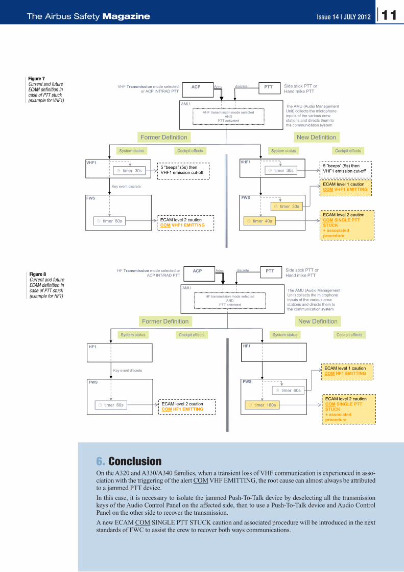
Figure 6 - Former and New Ecam definition in case of PTT stuck (example for VHF1)
VHF Transmission mode selected or ACP INT/RAD PTT
Side stick PTT orHand mike PTT
ACP PTT
AMU
VHF transmission mode selectedAND
PTT activated
discreteArinc
The AMU (Audio Management Unit) collects the microphone inputs of the various crew stations and directs them to the communication system
Transient Loss of Com due to jammed PTT - Draft 04
Former Definition New Definition
Cockpit effectsSystem statusCockpit effectsSystem status
© AIRBUS Operations S.A.S. Tous droits réservés. Document confidentiel.
ECAM level 2 cautionCOM VHF1 EMITTING
FWS
Key event discrete
VHF1
timer 30s
timer 60s
5 “beeps” (5s) then VHF1 emission cut-off timer 30s
5 “beeps” (5s) then VHF1 emission cut-off
VHF1
timer 40s
timer 30s
ECAM level 1 cautionCOM VHF1 EMITTING
ECAM level 2 cautionCOM SINGLE PTT STUCK+ associated procedure
FWS
Figure 7 - Former and New Ecam definition in case of PTT stuck (example for HF1)
HF Transmission mode selected or ACP INT/RAD PTT
Side stick PTT orHand mike PTT
ACP PTT
AMU
HF transmission mode selectedAND
PTT activated
discreteArinc
The AMU (Audio Management Unit) collects the microphone inputs of the various crew stations and directs them to the communication system
Transient Loss of Com due to jammed PTT - Draft 04
Former Definition New Definition
Cockpit effectsSystem statusCockpit effectsSystem status
© AIRBUS Operations S.A.S. Tous droits réservés. Document confidentiel.
ECAM level 2 caution COM HF1 EMITTING
FWS
Key event discrete
HF1
timer 60s
HF1
timer 180s
timer 60s
ECAM level 1 caution COM HF1 EMITTING
ECAM level 2 cautionCOM SINGLE PTT STUCK+ associated procedure
FWS
Figure 7Current and future ECAM definition in case of PTT stuck (example for VHF1)
Figure 8Current and future ECAM definition in case of PTT stuck (example for HF1)
6. ConclusionOn the A320 and A330/A340 families, when a transient loss of VHF communication is experienced in asso-ciation with the triggering of the alert COM VHF EMITTING, the root cause can almost always be attributed to a jammed PTT device.
In this case, it is necessary to isolate the jammed Push-To-Talk device by deselecting all the transmission keys of the Audio Control Panel on the affected side, then to use a Push-To-Talk device and Audio Control Panel on the other side to recover the transmission.
A new ECAM COM SINGLE PTT STUCK caution and associated procedure will be introduced in the next standards of FWC to assist the crew to recover both ways communications.
11Issue 14 | JULY 2012The Airbus Safety Magazine

Claude LELAIEexperimental Test Pilot
A380: Development of the Flight ControlsPart 2The Lateral Flight Control LawsOn July 27th 2005, in Toulouse we had a strong wind from the south, called “vent d’Autan”, giving rise to a lot of turbulence. It was flight 51 of the f irst A380. We performed several landings and it became apparent that the lateral flight control laws would have to be tuned again: the pi-lots were very active on the stick, the ailerons were moving a lot and created unpleasant lat-eral accelerations, mainly at the back of the aircraft. The flight test engineers had several pos-sibilities to adjust the control laws: gains, damping…, but none of them could solve the issue. This typical development flaw had to be corrected, but it was not an easy task.
Mid October, new PRIM flight controls computers were delivered with a new control law for the ailerons that the engi-neers of the design off ice called “VDA” or “Valse Des Ailerons” (ailerons waltz). As an example, when moving the stick to the left, on the left wing, the inter-nal aileron started to move up immediately. The outer aileron was doing the same, but with a different deflection. Finally, the centre aileron was either initially going down, in opposi-tion to the two others, then tak-ing an upward position, or going
up after a very short delay in a neutral position. Several adjust-ments were available for the flight engineers, for example, the ratio between the deflec-tion of inner and outer ailerons and the logic of the centre ai-leron. The target of this strange kinematic was to “break” some wing oscillations as two of them had very close frequencies and, in certain circumstances, they had the possibility to couple together. Looking at the page dedicated to the flight controls on the screen at the disposal of the crew, it was easy to under-stand why this strange motion of the ailerons received this nickname of “VDA”. A similar differential deflection was also implemented on the two rud-ders and was called “VDR” or “Valse Des Rudders” (rudders waltz), a typical Airbus “Bri-tish – French” acronym, as rud-der is not a French word! The improvement on comfort was spectacular. However, some tuning was still needed.
In January 2006, we installed a new standard of the computers, with some improvements on the VDA laws. The main one was a reduction in the activity of the ailerons. The adjustments were again performed in flight. The f inal tuning is such that, for speeds below 300 kts, the de-flection of the inner aileron is 2.5 times the value of the outer
one. The centre aileron follows the inner, but with a time delay of 350 milliseconds. Some more modif ications were needed at high altitude due to the Mach effect.
But we had another issue: the tuning of the spoilers. At the be-ginning, they were deflected as soon as there was a command in roll and this created some buf-fet. Mid February 2006, new settings were proposed by the design off ice in order to reduce these vibrations, with a limita-tion of the deflection to 3° as long as there was not a strong demand from the pilot. Without this trick, one of our British test pilots told us that he had the impression of being “punished” by this buffet when entering a standard turn! On top, in the f inal tuning, when more manoeuvrability was needed, there was a higher deflection of the outer spoilers than of the inner ones, because they were creating less buffet.
For all these flights where it was important to get an idea on the comfort, a qualitative judgement at various locations in the plane was needed. In the cockpit, the pilots gave their impressions, both on the ease of flying and on the comfort in the forward part of the aircraft. The flight test engineers, seating close to the centre of gravity, gave their sensations based on their
12 Issue 14 | JULY 2012 Safety

feelings and the available traces. At the back, close to the most rear door of the main deck, we installed a seat equipped with an intercom connected to the other crew members. A young flight test engineer was sat there, to give his opinion about his per-ception of comfort. Taking into account the number of roll ma-noeuvres we were performing on each flight, we had to hope that he would not become sick! It is true that a choice could have been made based on an analysis of the traces of several parameters of the motion at the various positions in the plane, but we considered that the opi-nion of a potential “passenger” was fundamental in order to make the f inal decision. Obvi-ously, all the records of these parameters were used by the design off ice to make progress in the tuning of the flight con-trols laws. It is to be noted that, at the beginning of the program, we were concerned by a possible difference of comfort between the two decks. The f irst flights demonstrated that this was not an issue.
At the opportunity of your next flight on an A380, if you travel in business or economy class, I recommend that you book a “window seat”, close to the wing or at the back of the plane in order to see how the ailerons are working (in f irst class you
will not have this chance as you will be too far forward!). The effect is best observed just af-ter take-off and during the early climb manoeuvres with the ai-lerons moving around their neu-tral position. You will see that when entering into a simple turn or for a unique roll correction, taking as a base the inner aile-ron, the one closest to you, the outer aileron will move simulta-neously but with a smaller de-flection. Then with a small time delay, the centre will join the inner. If several corrections are made by the pilot, in one direc-tion then in another, taking into account the different deflections and the time delay, you will see the ailerons in totally different positions, up and down. The nickname “Valse Des Ailerons” is really well chosen and it is ef-f icient.
The High Angle of Attack Protections at Low Mach NumberThe tuning of the high angle protections, that prevent loss of control for all types of manoeu-vres at low speed, has to be per-formed on all our new aircraft. The flight test techniques are well known by the test pilots.
We start with some decelera-tions with the engines at idle, slow manoeuvres at f irst and then faster, until achieving full back stick. At this stage, we have to check that we have some margin before reaching the stall. These tests are repeated in a stabilized turn and also with full thrust. If all the results are satisfactory, some rapid roll ma-noeuvres are carried out in one direction then in the other, while maintaining full back stick with various thrusts between idle and take-off power. The conclusion is the “avoidance manoeuvre” where the pilot rapidly puts the stick in the aft corner: a very
rapid turn will commence, the angle of attack will reach its maximum, and the engines will go to full thrust. This is exactly what a pilot would do to avoid another airplane or an obstacle. These tests must be performed for all slats and flaps positions. They must also be carried out for the extreme positions of the centre of gravity and with an aircraft light or heavy, as the reaction will be a function of all these parameters.
During the f irst flights of the A380, we performed an evalua-tion of these protections, but in a quasi-static way, with a slow deceleration. The reason was that we had to avoid approach-ing the stall because of potential high loads on the empennage. The engines were at idle and the target was to get a f irst idea of the tuning. During flight 7, at aft CG, we carried out some of these decelerations with satis-factory results.
The real tuning started when the slats and flaps deflections were frozen, end of July 2005, and immediately, we had a flight dedicated to these adjustments. We performed the tests at mid and aft CG, as the CG posi-tion could be adjusted in flight thanks to the water ballast sys-tem and when necessary some fuel transfer. During this flight, we avoided manoeuvres that were too dynamic, as we had still some doubts concerning the loads on some parts of the aircraft. The results were glo-bally good, with the exception of the configurations 3 and Full, where the angle of attack was not properly stabilised when at full back stick, with therefore a risk of reaching the stall. So, for these configurations, we ini-tially decided not to perform the turns with full back stick and maximum thrust.
The tuning continued with vari-ous standards of the PRIMs and, very quickly, in October 2005, the tuning of the protections was satisfactory. We proved that
13Issue 14 | JULY 2012The Airbus Safety Magazine

at the Dubai Airshow where we performed the standard flight display, with high angle of at-tack manoeuvres, similar to the display carried out on all other Airbus types.
The Effect of Icing on the Tuning of Low Speed ProtectionsHowever, the tuning of the protec-tions at low speed was not com-plete. We had to ensure that with some ice on the leading edge of the wing, the protection is still doing its job properly. This is not a critical issue on big transport jets, as due to their rather high speed, it is far more difficult to accumulate a large amount of ice on the wing than on smaller and slower aircraft. But the certification regulations are the same for everybody, and obvi-ously we had to comply.
Some tests are performed in real icing conditions, but it is not pos-sible to accumulate on the leading edge an amount of ice giving a shape representative of the “worst case” required by the regulations. Therefore, the aerodynamicists compute for all flight phases, the ice shapes for the wings and the empennages for the most critical conditions. In order to avoid per-forming several series of tests with different shapes, only the most critical for all flight conditions is retained.
The ice shapes are then manufac-tured. They are made of polysty-rene with some additional particles glued on in order to simulate the granularity of the ice. These shapes have a thickness of three inches, which is considered to be the maxi-mum that an aircraft will keep on a leading edge. The regulations also consider that the de-icing sys-tem may fail. In this failure case, the relevant part of the wing is equipped with a smaller ice shape, as the crew will follow the proce-dures to leave the icing area, and therefore will accumulate a smaller
amount of ice. These ice shapes are then glued on the leading edge for the duration of the tests.
With the shapes in place, the tests start with an evaluation of the han-dling qualities and some stalls in order to check if the margin be-tween the stall and the approach speed remains acceptable or not. If it appears that this margin has be-come insufficient, it is possible to recommend a small approach speed increase, such as 5 kts in case of se-vere icing or failure of the de-icing system. On the A380, none of the speeds or procedures needed to be changed in icing conditions.
The second step is to review the high angle of attack protections and adjust them, if necessary. The test techniques are identical to those used without ice shapes.
On the A380, on each wing, the slats are divided in seven sections and only slat 4, close to the outer engine, on the fuselage side, is de-iced. Within the flight test team, we were convinced that this de-icing was not necessary. What could be the effect of a couple of inches of ice on such a huge leading edge? This design change could save around sixty kilograms of weight (about half a passenger !). Therefore we decided to start the tests with a configuration without the de-icing, which means with the three inches leading edge ice shapes on all the wings, including slats 4.
The first flight with ice shapes was performed on June 26th 2006. As mentioned above, we started with the stalls. With flaps retracted, the
results were good. But there was a significant deterioration as the flaps were deflected. For the land-ing configuration, there was some loss of lift and a pitch up when approaching the stall. Our objec-tive was to keep a safe aircraft, without degradation of the perfor-mance. Retaining more or less the same tuning for the angle of attack protections would have been an acceptable solution to save weight and simplify the systems. But, due to the pitch up, it appeared that the maximum angle of attack with the protections, in the landing configu-ration, would have to be reduced by two degrees, which was really too much. And therefore, we had to keep the de-icing system on slat 4. The flight test team was wrong and the aerodynamicists were right!
The tests continued with the tuning of angle of attack protections. The maximum angle of attack remained unchanged from configuration Clean to 2. Then in configurations 3 and landing, there was a reduc-tion of 0.5 degree, without any consequence on the operation of the aircraft.
The tests were concluded with the validation of the failure case, a small ice shape on slat 4, with no other modification. Consider-ing the previous tests with this slat fully iced, we were anticipating some degradation of the handling qualities. All we found was a slight difficulty to maintain the bank an-gle precisely with full back stick in the landing configuration. This was found acceptable due to the fact
Figure 1Polystyrene shapes simulating ice accretion
14 Issue 14 | JULY 2012 Safety
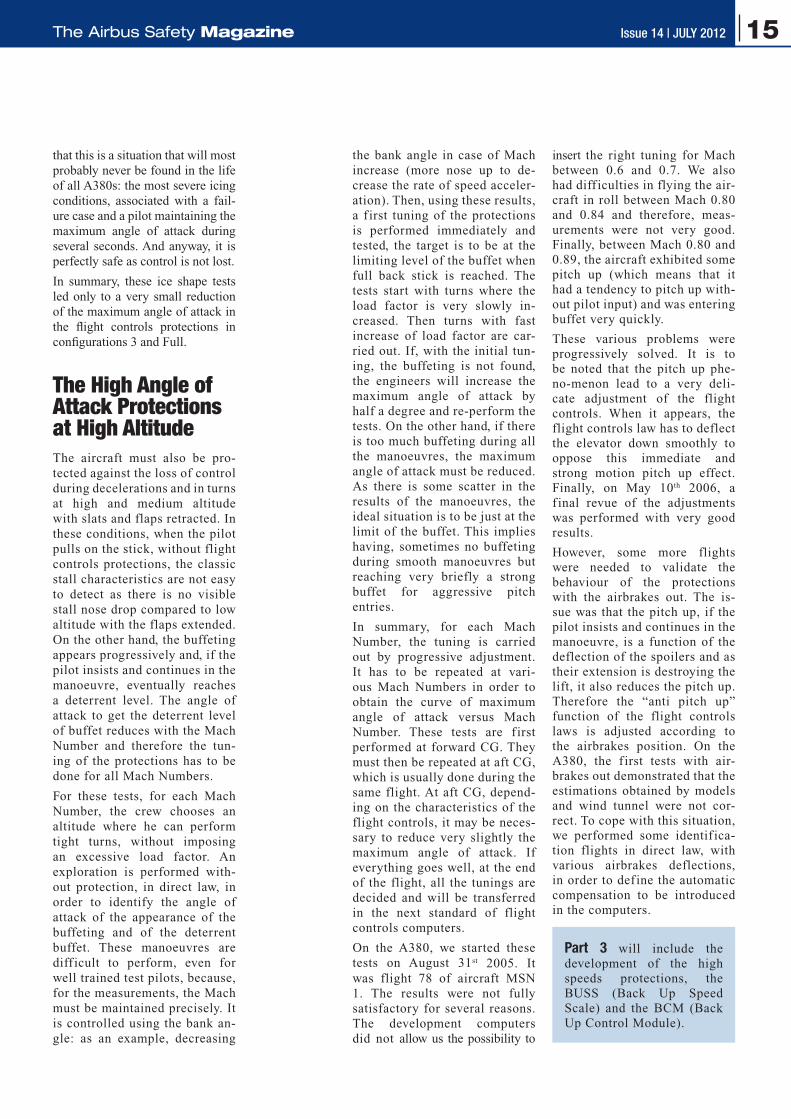
that this is a situation that will most probably never be found in the life of all A380s: the most severe icing conditions, associated with a fail-ure case and a pilot maintaining the maximum angle of attack during several seconds. And anyway, it is perfectly safe as control is not lost.
In summary, these ice shape tests led only to a very small reduction of the maximum angle of attack in the flight controls protections in configurations 3 and Full.
The High Angle of Attack Protections at High AltitudeThe aircraft must also be pro-tected against the loss of control during decelerations and in turns at high and medium altitude with slats and flaps retracted. In these conditions, when the pilot pulls on the stick, without flight controls protections, the classic stall characteristics are not easy to detect as there is no visible stall nose drop compared to low altitude with the flaps extended. On the other hand, the buffeting appears progressively and, if the pilot insists and continues in the manoeuvre, eventually reaches a deterrent level. The angle of attack to get the deterrent level of buffet reduces with the Mach Number and therefore the tun-ing of the protections has to be done for all Mach Numbers.
For these tests, for each Mach Number, the crew chooses an altitude where he can perform tight turns, without imposing an excessive load factor. An exploration is performed with-out protection, in direct law, in order to identify the angle of attack of the appearance of the buffeting and of the deterrent buffet. These manoeuvres are diff icult to perform, even for well trained test pilots, because, for the measurements, the Mach must be maintained precisely. It is controlled using the bank an-gle: as an example, decreasing
the bank angle in case of Mach increase (more nose up to de-crease the rate of speed acceler-ation). Then, using these results, a f irst tuning of the protections is performed immediately and tested, the target is to be at the limiting level of the buffet when full back stick is reached. The tests start with turns where the load factor is very slowly in-creased. Then turns with fast increase of load factor are car-ried out. If, with the initial tun-ing, the buffeting is not found, the engineers will increase the maximum angle of attack by half a degree and re-perform the tests. On the other hand, if there is too much buffeting during all the manoeuvres, the maximum angle of attack must be reduced. As there is some scatter in the results of the manoeuvres, the ideal situation is to be just at the limit of the buffet. This implies having, sometimes no buffeting during smooth manoeuvres but reaching very briefly a strong buffet for aggressive pitch entries.
In summary, for each Mach Number, the tuning is carried out by progressive adjustment. It has to be repeated at vari-ous Mach Numbers in order to obtain the curve of maximum angle of attack versus Mach Number. These tests are f irst performed at forward CG. They must then be repeated at aft CG, which is usually done during the same flight. At aft CG, depend-ing on the characteristics of the flight controls, it may be neces-sary to reduce very slightly the maximum angle of attack. If everything goes well, at the end of the flight, all the tunings are decided and will be transferred in the next standard of flight controls computers.
On the A380, we started these tests on August 31st 2005. It was flight 78 of aircraft MSN 1. The results were not fully satisfactory for several reasons. The development computers did not allow us the possibility to
insert the right tuning for Mach between 0.6 and 0.7. We also had diff iculties in flying the air-craft in roll between Mach 0.80 and 0.84 and therefore, meas-urements were not very good. Finally, between Mach 0.80 and 0.89, the aircraft exhibited some pitch up (which means that it had a tendency to pitch up with-out pilot input) and was entering buffet very quickly.
These various problems were progressively solved. It is to be noted that the pitch up phe-no-menon lead to a very deli-cate adjustment of the flight controls. When it appears, the flight controls law has to deflect the elevator down smoothly to oppose this immediate and strong motion pitch up effect. Finally, on May 10th 2006, a f inal revue of the adjustments was performed with very good results.
However, some more flights were needed to validate the behaviour of the protections with the airbrakes out. The is-sue was that the pitch up, if the pilot insists and continues in the manoeuvre, is a function of the deflection of the spoilers and as their extension is destroying the lift, it also reduces the pitch up. Therefore the “anti pitch up” function of the flight controls laws is adjusted according to the airbrakes position. On the A380, the f irst tests with air-brakes out demonstrated that the estimations obtained by models and wind tunnel were not cor-rect. To cope with this situation, we performed some identif ica-tion flights in direct law, with various airbrakes deflections, in order to def ine the automatic compensation to be introduced in the computers.
Part 3 will include the development of the high speeds protections, the BUSS (Back Up Speed Scale) and the BCM (Back Up Control Module).
15Issue 14 | JULY 2012The Airbus Safety Magazine

Preventing Fan Cowl Door Loss1. IntroductionParts Departing from Aircraft (PDA) have always represented a significant concern in aviation, and as such all events involving PDA need to be reported to Airbus, no matter the shape, material, size or weight.*
PDA may impact the aircraft and lead to structural damage, but they may also represent a danger to people on the ground.
When the part separation occurs close to an airport area, debris may fall on a runway, hence creating a risk for following aircraft.
This is particularly true for lost fan cowl doors, which are among the largest PDA, since more than 80% of the 32 reported events occurred during the take-off phase.
This article covers the published procedures and easy to imple-ment recommendations, for both mechanics and crew members, to avoid fan cowl door losses.
Xavier JOLIVET Director, Flight Safety
Stéphane RAMON Head of Repair & System, Nacelles engineering Support Customer Support
* Ref OIT SE 999.0038/09 & SIL 00-097
noteOn other Airbus programs, occurrences of fan cowl door loss are more limited:q 2 cases on the A330 q 3 cases on the A300/A310 Family.
Although more rare, these events also involve more severe damage, as the impact energy coud be higher than for the A320 Family (fuselage puncture leading to cabin decompression, wing skin puncture leading to fuel leak, for instance).
The higher number of occurrences on the A320 Family is mainly attributed to the lower ground clearance of the power plants.
Figure 1Fan cowl loss event
skin panel perforation or serious damage to the vertical or horizon-tal stabilizers. This type of damage represents a major hazard in terms of handling in flight and also often requires major repair work to rec-tify on the ground.
Potentially, any part of the aircraft structure located aft of the engines could be affected.
The grounding time for repair can typically last for up to several weeks.
2. Potential Heavy damage To AircraftOn the A320 Family, each fan cowl weights about 40 kg, hence it represents a potentially signifi-cant amount of energy, which may impact the aircraft when lost at high speed.
A fan cowl loss generally leads to twisted pylon cantilevers and/or minor damages to slats, wing leading edges, horizontal stabilizers and fuselage skins.
But the damage can also extend to
16 Issue 14 | JULY 2012 Safety

3. Incorrect Latching of Fan Cowl doors3.1 Recent EventA recent fan cowl door loss event highlights some recurring factors associated to such occurrences.
The aircraft originally planned for the flight had to be rescheduled due to a technical issue.
On the day preceding the event, the replacement aircraft had been subject to a weekly IDG oil check, which called for the opening of the engine cowlings. A subsequent daily check was carried out by the same person.
The event flight was the first leg of the day. Less than one hour be-fore the take-off, a transit check was performed. The exterior walk around was performed with time pressure and challenging weather conditions (temperature below 0°C and wind).
The engine fan cowls were lost four minutes after take-off, pass-ing FL110 during climb. The cowls perforated the engine oil tank and the crew shut down the engine.
Figure 2Latches on open doors should be left in the not engaged position
Post-flight inspection revealed a twisted pylon as well as multiple impacts to slats, horizontal stabi-lizer and the fuselage. The over-all repair required assistance by a working party for three weeks.
The investigation concluded that the aircraft had departed with the fan cowls not properly latched.
3.2 Typical Scenario
For all investigated events, it was established that maintenance ac-tions requiring opening of the fan cowls had taken place prior to the flight, and that the affected fan cowls were incorrectly latched.
Several independent risk factors were identified as the main contrib-utors to fan cowl door losses:
q First flight of the day
q Poor weather conditions (low temperature, rain, snow, wind)
q Time constraints due to a late aircraft change
q Changes to the routine of the maintenance team during tasks in-volving opening of the fan cowls.
4. Maintenance RecommendationsIn the chain of preventive meas-ures, maintenance is a key factor.
Airbus insists about the need for strict adherence to the AMM 71-13-00 instructions, for proper latching and closing of the fan cowl doors.
Please note the following key recommendations:
q The fan cowl doors should always be entirely latched when they are being closed. If it is necessary to walk away from the engine prior to completing the latching, the doors should not be left unlatched, or partially un-latched.
If the aircraft walk-around is not performed in an exhaustive manner, the situation may remain unnoticed.
q Latches on open doors should always be left in a “not engaged” position, which means that they will hang down when the doors are closed and not latched (fig.2).
This ensures easy identification of an unlatched door condition.
CORRECT The latches are not
engaged on the hook
INCORRECT The latches are engaged
on the hook
“Engaged” but unfastened latches may not allow easy identification that the
cowls are not properly latched.Latches are visible when cowls are closed
17Issue 14 | JULY 2012The Airbus Safety Magazine

noteIn the frame of an investigation, the US National Transportation Safety Board (NTSB) has found that Airbus operators who introduced dual inspection sign-offs to their maintenance inspection procedure, to confirm latching of engine fan cowls, were successful in preventing cowl loss events.
5. A320 Family design EvolutionA number of modifications were developed to ease the detection of an unlatched cowl condition (ref. 1 & 2). In particular:
q Fluorescent paint on the latch
q Hold-Open device (IAE en-gines) to increase the peripheral gap
q New latch handle hook springs to ensure handle hanging down when unlatched
q Caution decal on the cowl.
The latest modification consists of the introduction of red flags, to improve the visibility of an unlatched condition of the cowls:
q On the IAE engine, a dedicat-ed tool (P/N 98D71103002000) is included in Airbus’ Tool and Equipment Manual (TEM). This new tool is called by the AMM at every Fan Cowl Door opening (Fig. 3).
q On the CFM engine, a similar tool is under development, to be finalized by end of Q4 2012.
6. Importance of the Pre-Flight CheckFCOM Standard Operating Procedures PRO-NOR-SOP-05 provide instructions to the crew to perform the exterior walk-around and ensure that the overall condition of the aircraft and its visible components and equipments are secure for the flight.
Figure 3A320 red flag
on the IAE engine Hold-Open device
As part of this inspection, it is essential that a flight crew mem-ber visually inspects the fan cowl doors prior to each flight to ensure that they are closed and latched (ref. 3, fig. 4).
The effectiveness of this check re-lies on the correct positioning of the flight crew to visually check that all
The following cautions will be added to AMM 71-13-00 in the August 2012 revision:
CAUTION:DO NOT LEAVE THIS JOB AFTER JUST CLOSING THE FAN COWLS, CONTINUE ON TO SECURE THE LATCHES. IF YOU ARE CALLED AWAY PRIOR TO LATCHING, THEN EITHER RE-OPEN ONE COWL DOOR OR LATCH THE LATCHES BEFORE WALKING AWAY FROM THIS ENGINE.
CAUTION:DO NOT ENGAGE THE LATCH HANDLE HOOKS WHEN THE FAN COWL DOOR ARE OPENED
the handles are flush with the cowls and engaged in their slots.
Indeed, the crew member per-forming the walk-around needs to position himself on the side of the engine and should crouch to check that all latches are cor-rectly latched and that there is no gap around the cowl (fig. 5).
18 Issue 14 | JULY 2012 Safety

7. ConclusionFan cowl doors that are not properly latched may lead to the in-flight loss of the cowls. This may cause extensive damage to the aircraft structure and result in operational consequences such as in-flight turn back and subsequent long grounding periods for repair. They may also represent a danger to people on ground, as well as a threat to following aircraft when lost at take-off.
Specific focus on AMM maintenance instructions and SOPs, are key safety barriers to avoid such events.
The following three recommendations should be followed by maintenance personnel and crew members:
q Latches on doors in the fully open position should always be left in the horizontal (i.e. not engaged) position.
q Fan cowl doors should always be entirely latched when the cowls are being closed. Cowls must not be left in the closed position while not properly latched.
q During the exterior walk-around, the crew member has to visually check the correct closure/latching condition of the fan cowls. To do this correctly, the crew member must be positioned on the side of the engine and crouch.
References:
q Ref. 1: OIT 999.0057/07: Fan cowl door loss after take-off
q Ref. 2: Maintenance Briefing Note (MBN): Human factor – error management (case study on fan cowl loss prevention)
q Ref. 3: OIT/FOT Ref 999.0122/07 Walk-around check.
ExTERIOR WALK-AROUND Applicable to: ALL
SCHEMATIC
ENG 2 LH SIDEOil fill access door (CFM and IAe only)............................... CLOSeDMaster magnetic chip detector access door (IAe only) ...... CLOSeD* Thrust Recovery Nozzle (PW only) ................. CLOSeD/LATCHeDHydraulic filter visual access door (PW only) ..................... CLOSeD* Fan cowl doors .............................................. CLOSeD/LATCHeD* Drain mast ..................................................... Condition/NO LeAK* engine inlet and fan blades................................................ CHeCK
ENG 1 LH SIDEOil fill access door ...........................................................CLOSeD* Fan cowl doors ........................................... CLOSeD/LATCHeD* Drain mast ..................................................Condition/NO LeAK* engine inlet and fan blades.............................................CHeCK
Figure 5Proper walk-around
check for secured fan cowl doors
Figure 4FCOM Exterior
walk-around check
All latches are flush + the cowl is flush
=> cowl is secured
The latches are not flush* + there is a gap around the cowl
=> cowl is not secured
* This picture represents the worst case scenario, where the latches are engaged on the hooks, but unfastened
19Issue 14 | JULY 2012The Airbus Safety Magazine

Do not forget that you are not alone in Maintenance
1. IntroductionThe aim of this article is to high-light the importance of being aware of what other maintenance team co-workers are doing, and where they are working on the aircraft at the same time. The potential con-sequences can be dramatic when this awareness is lost, as shown by this article.
Maintenance teams are working in an environment where they are faced with ever more complex air-craft systems and the increased in-teraction of co-workers performing different tasks at the same time on the same aircraft.
Being aware of who is doing what, and understanding the consequences of tasks being performed is essen-tial, to avoid potentially dramatic situations.
uwe EGGERLING Safety Director engineering & Maintenance Customer Services
It was also confirmed that head set communication was present be-tween the cockpit operator and the hangar area, and visual alert signs were located around the work areas.
Good standard maintenance prac-tice would require to do a walk-around to be carried out. The person who activated the hydraulic system did not, through such a check, con-firm that there was no risk to other personnel prior to energising the hy-draulic system.
Case No. 2: Injuries caused by the Nose Landing door closureA mechanic was working alone within the landing gear bay on an A320 Family aircraft. For an un-determined reason, the ground door opening handle was in the “closed” position, i.e. not corresponding to the actual position of the nose land-ing doors (fig. 1).
Another person, not being aware that a mechanic was already work-ing within the landing gear bay, activated the hydraulic system; the doors closed accordingly and trapped the mechanic.
2. Maintenance Event descriptionLoss of situational awareness in maintenance operations can have serious consequences. In the least it can lead to damage to the aircraft, and in the worst case can result in fatal injuries to maintenance work-ers involved in the incident, as two recent cases have highlighted.
Case No. 1: Accident with the Krueger flapDuring a scheduled maintenance check, an experienced licensed mechanic was cleaning an area between the extended Krue-ger flap and the structure on an A300-600.
During the performance of this maintenance task, the slats started retracting, causing the head of the mechanic to be impacted by the moving Krueger flap at the end of the slat system retraction cycle.
The investigations performed fur-ther to this accident confirmed that the warnings and precautions as per the AMM were clear.
20 Issue 14 | JULY 2012 Safety

3. The Aircraft Maintenance ManualThe AMM is written with specific warnings and cautions detailing safety procedures and tooling that should be used. These Warning Notices typically ensure that the controls agree with the position of the surfaces they operate, and to operate the controls only when the related hydraulic systems are pres-surized.
The use of the correct tooling will prevent the doors from closing, if the hydraulic system is pressurised Inadvertently.
The aim of these safety steps is to highlight particular risks, and to reduce the risk of injury to the me-chanics.
4. The Lessons LearnedThe common factor between the two described accidents was that even though the maintenance doc-umentation provided clear warning advice, fatal injuries were caused to the workers in question.
In both events, investigation showed that more than one individ-ual was working on the aircraft at the time, but on different assigned tasks.
None of them had made a mainte-nance error related to the tasks he was working on. However, a com-bination of actions taken led to the situation that put one of the work-ers lives at risk.
All of these difficulties point to a lack of having a clear and up to date understanding of what was go-ing on around the aircraft. It dem-onstrates the importance of being aware all the time of the state of the aircraft systems, and sub-systems, that may be being working on.
A common situation is that per-sonnel carrying out part of a ma-jor maintenance task, without the awareness and knowledge as to how their actions are affecting the overall task, or aircraft tech-nical configuration, i.e. having
q MAKE SURE THAT THE CONTROLS AGREE WITH THE POSI-TION OF THE ITEMS THEY OPERATE BEFORE YOU PRES-SURIzE A HYDRAULIC SYSTEM. UNWANTED MOVEMENT OF HYDRAULICALLY OPERATED ITEMS CAN LEAD TO SERIOUS INJURY AND / OR CAUSE DAMAGE.
q ONLY OPERATE CONTROLS WHEN THE RELATED HYDRAULIC SYSTEMS ARE PESSURIzED.
q IF YOU OPERATE A CONTROL WHEN THE RELATED HYDRAU-LIC SYSTEM IS NOT PRESSURIzED, THERE IS A RISK THAT:– THE CONTROL WILL BE IN A POSITION THAT DOES NOT
AGREE WITH THE ITEM(S) IT OPERATES.– WHEN HYDRAULIC PRESSURE IS RESTORED, UNWANTED
MOVEMENT OF THE HYDRAULICALLY OPERATED ITEM(S) MAY OCCUR AND CAUSE SERIOUS INJURY AND / OR CAUSE DAMAGE.
ON THE GROUNDq MAKE CERTAIN THAT THE GROUND DOOR OPENING CONTROL
HANDLE IS LOCKED IN THE OPEN POSITION,q REMOVE THAT THE SAFETY PIN FROM THE DOORS,q MAKE CERTAIN THAT THE DOOR TRAVEL RANGES ARE CLEAR
In addition, the “Doors Closing Preparation” of the Technical Training Manual includes a caution, which highlights the following messages:
Figure 1A320 Nose Landing
Gear operation mechanism
Taking the two examples above, details of the warnings and cautions are as follows:
21Issue 14 | JULY 2012The Airbus Safety Magazine

lost the “big picture”, also com-
monly known as “tunnel task-
ing”. Often technicians are given
only their piece of the puzzle, for
example, being assigned tasks
with deadlines without explana-
tion or direction – a “just do it”
assignment.
The difficulty in ensuring safety
whilst working on aircraft sys-
tems is increased by the fact that
many different individuals may
be working on the aircraft. The
presence of multiple individuals
increases the need for good and
clear communication between
them, and clear understanding of
responsibilities.
In addition to the awareness of
what the different team members
within one given team are do-
ing, another important task for
maintenance teams is the co-or-
dination and information transfer
across different teams, for exam-
ple during shift hand-over.
5. ConclusionA recurring source of accidents or incidents during maintenance is caused by loss of situational awareness. Technicians are often made aware of only part of a major maintenance task. Problems can occur when they are not trained or explanations are not provided of how their activities could affect other people working at the same time on the aircraft.
As part of preventive measures, individuals, training organisations, and management should ensure effective shift preparations, com-munications between all involved working on the aircraft, and avoid being trapped in a “tunnel task” situation, which can have fatal consequences.
Figure 2A possible consequence of the lack of awareness in the hangar
22 Issue 14 | JULY 2012 Safety

Issue 13, January 2012– A320 Family / A330 Prevention and
Handling of Dual Bleed Loss
– The Fuel Penalty Factor
– The Airbus TCAS Alert Prevention (TCAP)
– A380: Development of the Flight Controls - Part 1
– Facing the Reality of Everyday Maintenance Operations
Issue 12, July 2011– Airbus New Operational Landing Distances
– The Go Around Procedure
– The Circling Approach
– VMU Tests on A380
– Automatic Landings in Daily Operation
Issue 11, January 2011– What is Stall?
How a Pilot Should React in Front of a Stall Situation
– Minimum Control Speed Tests on A380
– Radio Altimeter Erroneous Values
– Automatic NAV Engagement at Go Around
Issue 10, August 2010– A380: Flutter Tests
– Operational Landing Distances: A New Standard for In-flight Landing Distance Assessment
– Go Around Handling
– A320: Landing Gear Downlock
– Situation Awareness and Decision Making
Issue 9, February 2010– A320 Family: Evolution of Ground Spoiler Logic
– Incorrect Pitch Trim Setting at Takeoff
– Technical Flight Familiarization
– Oxygen Safety
Issue 8, July 2009– The Runway Overrun Prevention System
– The Take Off Securing Function
– Computer Mixability: An Important Function
– Fuel Spills During Refueling Operations
Issue 7, February 2009– Airbus AP/FD TCAS Mode:
A New Step Towards Safety Improvement
– Braking System Cross Connections
– Upset Recovery Training Aid, Revision 2
– Fuel Pumps Left in OFF Position
– A320: Avoiding Dual Bleed Loss
Issue 6, July 2008– A320: Runway Overrun
– FCTL Check after EFCS Reset on Ground
– A320: Possible Consequence of VMO/MMO Exceedance
– A320: Prevention of Tailstrikes
– Low Fuel Situation Awareness
– Rudder Pedal Jam
– Why do Certain AMM Tasks Require Equipment Resets?
– Slide/raft Improvement
– Cabin Attendant Falling through the Avionics Bay Access Panel in Cockpit
Issue 5, December 2007– New CFIT Event During Non Precision Approach
– A320: Tail Strike at Takeoff?
– Unreliable Speed
– Compliance to Operational Procedures
– The Future Air Navigation System FANS B
Issue 4, June 2007– Operations Engineering Bulletin Reminder Function
– Avoiding High Speed Rejected Takeoffs Due to EGT Limit Exceedance
– Do you Know your ATC/TCAS Panel?
– Managing Hailstorms
– Introducing the Maintenance Briefing Notes
– A320: Dual hydraulic Loss
– Terrain Awareness and Warning Systems Operations Based on GPS Data
Issue 3, December 2006– Dual Side Stick Inputs
– Trimmable Horizontal Stabilizer Damage
– Pitot Probes Obstruction on Ground
– A340: Thrust Reverser Unlocked
– Residual Cabin Pressure
– Cabin Operations Briefing Notes
– Hypoxia: An Invisible Enemy
Issue 2, September 2005– Tailpipe or Engine Fire
– Managing Severe Turbulence
– Airbus Pilot Transition (ATP)
– Runway Excursions at Takeoff
Issue 1, January 2005– Go Arounds in Addis-Ababa due to VOR Reception Problems
– The Importance of the Pre-flight Flight Control Check
– A320: In-flight Thrust Reverser Deployment
– Airbus Flight Safety Manager Handbook
– Flight Operations Briefing Notes
Articles Published in Previous Safety First Issues
23Issue 14 | JuLY 2012The Airbus Safety Magazine

Subscription Form
Safety

The Airbus Safety Magazine
Subscription Form To be sent back to
AIRBUS FLIGHT SAFETY OFFICEFax: 33 (0)5 61 93 44 29Mail to: [email protected]
Name . . . . . . . . . . . . . . . . . . . . . . . . . . . . . . . . . . . . . . . . . . . . . . . . . . . . . . . . . . . . . . . . . . . . . . . . . . . . . . . . . . . . . . . . .
Surname . . . . . . . . . . . . . . . . . . . . . . . . . . . . . . . . . . . . . . . . . . . . . . . . . . . . . . . . . . . . . . . . . . . . . . . . . . . . . . . . . . . . . . .
Job title/Function. . . . . . . . . . . . . . . . . . . . . . . . . . . . . . . . . . . . . . . . . . . . . . . . . . . . . . . . . . . . . . . . . . . . . . . . . . . . . . . . .
Company/Organization. . . . . . . . . . . . . . . . . . . . . . . . . . . . . . . . . . . . . . . . . . . . . . . . . . . . . . . . . . . . . . . . . . . . . . . . . . . . .
Address . . . . . . . . . . . . . . . . . . . . . . . . . . . . . . . . . . . . . . . . . . . . . . . . . . . . . . . . . . . . . . . . . . . . . . . . . . . . . . . . . . . . . . . .
. . . . . . . . . . . . . . . . . . . . . . . . . . . . . . . . . . . . . . . . . . . . . . . . . . . . . . . . . . . . . . . . . . . . . . . . . . . . . . . . . . . . . . . . . . . . . .
. . . . . . . . . . . . . . . . . . . . . . . . . . . . . . . . . . . . . . . . . . . . . . . . . . . . . . . . . . . . . . . . . . . . . . . . . . . . . . . . . . . . . . . . . . . . . .
Post/Zip Code . . . . . . . . . . . . . . . . . . . . . . . . . . . . . . . . . . . . . . . . . . . . . . . . . . . . . . . . . . . . . . . . . . . . . . . . . . . . . . . . . . .
Country . . . . . . . . . . . . . . . . . . . . . . . . . . . . . . . . . . . . . . . . . . . . . . . . . . . . . . . . . . . . . . . . . . . . . . . . . . . . . . . . . . . . . . . .
Telephone . . . . . . . . . . . . . . . . . . . . . . . . . . . . . . . . . . . . . . . . . . . . . . . . . . . . . . . . . . . . . . . . . . . . . . . . . . . . . . . . . . . . . .
Cell phone . . . . . . . . . . . . . . . . . . . . . . . . . . . . . . . . . . . . . . . . . . . . . . . . . . . . . . . . . . . . . . . . . . . . . . . . . . . . . . . . . . . . . .
Fax . . . . . . . . . . . . . . . . . . . . . . . . . . . . . . . . . . . . . . . . . . . . . . . . . . . . . . . . . . . . . . . . . . . . . . . . . . . . . . . . . . . . . . . . . . .
E-mail . . . . . . . . . . . . . . . . . . . . . . . . . . . . . . . . . . . . . . . . . . . . . . . . . . . . . . . . . . . . . . . . . . . . . . . . . . . . . . . . . . . . . . . . . . . . . . . . . . (Mandatory for both digital and paper copies)
Please send me the digital copy* P
Please send me the paper copy* P (Please note that paper copies will only be forwarded to professional addresses)
* Please tick the appropriate case
Safety
23

Edition July 2012