Embed Size (px)
Citation preview
1
THE ADVANTAGES & REQUISITE CONSIDERATIONS OF SLIM-HOLE
DRILLING Dr Michael Gibson, IDEAS Singapore Ltd.
ABSTRACT This paper portrays the key drivers behind successful slim-hole drilling so that wells are drilled economically and successfully and are able to meet their objectives. The paper also discusses the reasons behind success and failures of slim-hole wells and what can be done to maximise success first time and minimise failure.
Given the potential cost savings of slim-hole wells (whether exploration, appraisal or re-development) during this long oil-price crash period, understanding slim-hole drilling has the potential to significantly reduce an operator’s drilling budget whilst maximising portfolio gains.
INTRODUCTION
Recent advances in slim-hole drilling technology have improved the application of this drilling technique to oil and gas exploration, appraisal and re-development wells especially as exploration budgets become smaller and re-development budgets tighten due to the reduction in oil price.
Typically, slim-hole drilling operations used technology borrowed from the mining industry. Such rigs are smaller and much more economic. However, the change in size of rig, drill pipe and BHA’s present their own unique set of challenges, not just for the drill crew but also downhole dynamics. Standard-sized rigs may also be used, providing the crews have been trained to handle and drill with much smaller diameter pipe than they are used to. (2 7/8” drill pipe handles very differently to 5” drill pipe for example and has radically different tensile and torsional limitations whilst drilling).
Definitions of slim holes vary from a well with 90% drilled with a diameter of less than 7 in. to a well with 70% drilled with less than 5 in. A goal of slim hole, however it is defined, is the drilling of a well with a diameter smaller than that used on conventional wells in the area. The reduced diameter helps cut rig time and cost and reduces the cost of the tubulars (if the planning and operational practices are right).
The following areas are key to the success of such wells.
2
SLIMHOLE HYDRAULICS
A model based on fluid mechanics helps optimize slim-hole drilling hydraulics by taking into account mud rheology, drill-string rotation, and the eccentric position of the drill-string.
Drilling hydraulics can become a problem in sedimentary formations drilled with slim-hole drilling equipment because of the typically utilized high rotational speeds and small annuli.
The crucial areas include the lifting of cuttings in the annulus, well bore stability, bit cleaning, differential mud pressure in the annulus, and the hydrodynamic lubrication between the drill-string and the well bore.
The annular mud velocity profile must be kept as uniform as possible to ensure that cuttings are transported to the surface without balling up in the annulus. In general, a mud velocity of about 0.5 m/sec (1.6 fps) should keep cuttings moving faster than the sedimentation velocity in the annulus.
In soft sedimentary formations, a laminar flow regime is important in the annulus to minimize the shear stress close to the borehole wall. High shear stresses close to the wall can cause erosion and caving.
In slim-hole drilling, the trajectory of the mud and cuttings becomes helicoidal, and not straight as in conventional wells. The rotating drill-string forces the mud to rotate because of the viscous “Couette” effect.
Another slim-hole drilling hydraulics phenomenon, the “Crescent” effect, occurs when the drill-string rotates eccentrically in the well, with the eccentric geometry influencing the pressure losses in the annulus. Although eccentricity occurs in conventional wells, the effect on pressure losses is not as great.
Thus, the dynamic component of the annular pressure is much more important in slim-hole drilling than in conventional drilling.
WEIGHTING AGENT
A finely ground material is ideal for use in slim-hole operations. In slim-hole continuous coring and drilling operations, conventional weighting materials may become deposited on the inner wall of the drill-string because of the high rotational speeds typically used. These deposits on the inner wall of the drill-string cause problems with retrieving cores by wire line (if for example the “Coredrill” system is used).
A pigment grade barite works well to weight cationic brine muds in excess of 14 ppg. with acceptable viscosity. Typical oil field barite ground to an ultrafine size should
3
work comparably well to the pigment grade barite. (The pigment grade is purer than conventional oil field barite, and it is predominantly used as a paint pigment or plastics filler).
The pigment grade barite does not interfere with wire-line core retrieval within reasonable operating ranges of drilling parameters, according to S.B. Randolph, S.H. Walker, G.A. Young, and D.S. Dorrough of Amoco Production Co. in "Use of a unique weighting agent for slim-hole drilling."
In slim-hole wells, well control can become a problem because of the small annular clearances, often less than 1/2 in. Well control is typically maintained through either dynamic well control methods or heavy fluids. The weighted brines are expensive, and conventional coarse barite can form deposits or bridges in the annulus.
The pigment grade barite can be obtained through certain suppliers of industrial solids. Although it costs somewhat more than conventional barite, small amounts are used, and little mud is lost in slim-hole wells.
The pigment grade barite has a size distribution of 80% less than 1 micron and 50% less than 0.18 micron. Conventional coarse barite has a size distribution much greater than these figures.
The pigment grade barite can formulate muds with low viscosity, which is acceptable in slim-hole drilling because the cuttings are fine and easily transported up the annulus. This barite does not readily settle out of thin drilling muds because the particles are so small.
The weighted mud can be pumped through a centrifuge rotating at reduced speed to discard the low gravity solids without loss of too much of the finely ground barite. The pigment grade barite can be mixed into the mud system with a hopper and standard mixing procedures.
HIGH ANGLE WELLS
Slim hole drilling technology can particularly reduce drilling costs in high angle wells because of the use of smaller drilling rigs, smaller casing sizes, and minimized drilling wastes.
However, the cost savings achieved from slim-hole drilling can be offset by increased mechanical failures, reduced hole length, and sometimes a lack of directional control.
The decision to drill a slim-hole (3 7/8 in. / 4 3/4 in. / 6” hole) compared to a conventional hole of 8 1/2 in.) requires involvement from all departments associated with the well to prevent the limitations of the smaller well bore from exceeding the benefits.
4
The limitations of downhole equipment have often precluded drilling lateral intervals with less than 6 in. diameter. Until recently, the cost savings of smaller tubulars would be more than offset by lower rates of penetration or directional control problems.
Oryx have drilled a number of re-entry horizontal slim-hole wells, two of which were drilled with a coiled tubing rig. The conventional rig operations used a wet connect steering tool system and a modified power swivel assembly through which the steering tool cable could be run. The results from these wells were promising.
Oryx then drilled two horizontal slim holes in the Pearsall field in South Texas. The program used a small drilling rig for drilling from surface to the intermediate casing point. This rig was released and replaced with a workover rig. The small drilling rig could drill the upper hole more quickly than the workover rig, and the less expensive workover rig could handle the small tubulars for the horizontal section more easily.
Recently developed small diameter (3 3/8 in.) measurement while drilling (MWD) tools were used instead of a wet connect steering system.
The first well (4 1/2 in.) encountered a high number of mud motor failures, some minor problems with the small MWD tool, and difficulties with fishing because of the small hole and high angle (20 degs/100 ft).
The second well (4 3/4 in.) used larger mud motors which could better handle the torque of the polycrystalline diamond bits. This well also used 2 7/8 in. drill pipe in part of the curve to increase the weight on bit. With more torque available and more aggressive bit designs, the rate of penetration on this well increased 125% more than that for the first well.
The costs for this slim horizontal well were 20% less than the costs for the first well and 32% less than the costs of a conventional design.
SLIMHOLE WELL CONTROL
Established conventional well control standards can be applied with almost no modification to drilling using downsized conventional equipment, provided a sensitive kick detection system (KDS) and the hard shut-in procedure are used.
Early proposals for continuous coring included the concept of dynamically killing the well after a kick. This method has not yet found wide acceptance in the industry since it depends on the utilisation of poorly understood hydraulic phenomena, places higher demands on the driller, and has fewer redundancies than the industry standard methods, which are based on the “shut-in-and-think” concept. However, a simple, practical modification to the industry standard well control method has been published which works well.
If a slim hole is drilled into a prolific formation and well control is lost, then a smaller hole will have a lower open hole production potential in the event of a blowout. This

5
will reduce pollution and may make a surface kill and intervention by a snubbing unit easier. The downsized conventional approach incorporates full directional and homing-in capability and may be used for relief well drilling, but the maximum possible injection (dynamic kill) rate is less than that possible with conventional hole sizes.
SAFETY OF PERSONNEL
Smaller wells mean smaller individual items of equipment and tubulars and a smaller total amount of material to be handled, which reduces the total exposure of rig-site personnel. Smaller rigs require smaller crews, and are easier to mechanise/automate than bigger rigs because the range of tubular size to be handled is smaller. They thus have the potential, in the longer term, of reducing total exposure even further, though consideration must also be given to the smaller dimensions of the workspace available.
Smaller rigs mean a reduction of the heaviest lift during rig move from about 30 tons to about 10 tons. The heaviest tubular to be handled can be reduced, for example from a 4-ton joint of 20" casing to a joint of 9 5/8" weighing 1 ton or less.
Where the smaller volume of materials enables a materials staging base to be eliminated, a step change in exposure can be realised. In the specific case of helicopter-supported operations, this lower total volume of materials can result in a significant reduction in total exposure as well as transport cost.
EVALUATION OF SLIMHOLE WELLS
Conventional evaluation techniques such as mud logging, wireline logs, conventional coring, production testing, as well as on-site core evaluation, are now all available commercially for small boreholes.
Wireline & Logging
Wireline logging companies have HP/HT 2 3/4" diameter logging tools, and a range of 2 1/4" tools, including formation pressure sampling for normal pressures and temperatures. The major wireline service companies have a wide and sophisticated range of logging tools for 8 1/2"- 5 7/8" hole.
High angle holes of 3 7/8" and larger have been logged by wireline tools run on drill-pipe, tubing work-string, or coiled tubing.
All the interpretation charts and software are calibrated for conventional hole sizes. Smaller holes mean that all these charts, many of which are empirical, have to be extended, to ensure that they result in consistent correlation with existing larger sized wells.

6
Conventional coring
Conventional core barrels which are retrieved by tripping the whole drillstring are available in small sizes. One manufacturer has developed a non-rotating (inner barrel) low vibration 3 3/4" OD coring system for cutting a 2" core in 4 1/8" and larger hole. The design of these tools was carried out with the objective of cutting the core with the minimum of mechanical disturbance and fluid invasion. This is especially important in friable or fractured formations.
Continuous coring
Continuous coring is best utilised with on-site core evaluation, or inverse logging. Amoco have built and are operating a number of systems in house. BP and partners have developed a commercial system. It can handle 150 metres of core a day, giving gamma ray, density, porosity and permeability measurements, source rock evaluation, digitised video image, and geological description. Due to reduced rates of penetration (ROP) while coring, the less interesting parts of the geological column are often drilled destructively. Therefore wireline logs are usually run to get a continuous record, to ensure core-to-hole correlation by gamma ray, to estimate in situ saturations, and to tie the well to seismic data using the sonic log.
Production testing
Service companies have equipment for 3" open holes. A range of testing equipment for slightly larger hole sizes is available, including a fully enclosed burner which will allow location size to be reduced. For extended tests, a 3 1/2" monobore completion offers a cheap, reliable and flexible option. It also allows fine resolution of reservoir properties such as inflow capacity, skin, sand production, etc. Such vertical resolution will become increasingly important as field development by horizontal wells is becoming the norm.
DRILLING & DRILLING EQUIPMENT
BHA: DRILLBITS
PDC BIT DOME CUTTERS / TORQUE REDUCTION / IMPACT RESISTANCE
Dome polycrystalline diamond compact (PDC) technology on small diameter bits and under-reamers has opened opportunities for re-entering old producing wells.
The dome PDC has a radius of curvature across the diamond table rather than the typical flat table. This design reduces torque and dissipates heat better than conventional PDCs. Because the structure is very impact resistant, the dome PDC has potential for harder rock applications.
The dome PDC cutters (3 ¼” / 4 ¾”) have proven successful even whilst drilling hard dolomitic limestone.
7
The weakness in conventional small diameter roller cone bits has been the bearings, not the cutting structure. The bit runs have been short, often with junk left in the hole. Conventional flat PDC cutters have also been tried, but these were destroyed early in the drilling, resulting in a high cost per foot.
Under-reaming prior to running the liner has been effective in improving cement bonds and offers the opportunity to run larger diameter liners. This task is difficult with conventional slim-hole roller cone technology because the rigorous drilling conditions of the hard rock formations wear the tools fast, often leaving junk in the hole.
The use of dome PDC cutters on under-reamers in these wells has reduced costs by more than 60% compared to similar costs for roller cone tools. The savings resulted mainly from an increase in penetration rates to more than 30 ft./hr. from 10 ft./hr.
PDC/TSD/impregnated diamond bits, often of anti-whirl design and 4 3/4", 4 1/8", 3 7/8" hard formation sealed-bearing roller cone rock bits are also available.
BHA
High-power Moineau motors. As hole size declines the available mechanical power per unit of hole area increases. Motors are available for hole sizes 2 5/8" and larger. High temperature motors suitable for bottom-hole temperatures of 180°C and above are available. In principle, motors of all sizes can be made steerable. 3 1/8" OD motors for drilling 3 7/8" horizontal holes using steering tools or 3 1/8" MWD for guidance are available.
Thruster to isolate the longitudinal and transverse vibrations in the drill-string from the BHA, to provide constant WOB and to minimise the drill collars required. Thrusters are available for hole sizes 2 5/8" and larger.
Soft torque rotary table or top drive to stop torsional vibrations being reflected back down the drill-string from surface.
Drillpipe For 4 1/8" and 4 3/4" hole a 2 7/8" DP string has been developed. This has conventional upsets for ease of handling and minimum ECD, but with advanced thread profile for maximum strength and fatigue resistance. Special HWDP for running in compression instead of using DC’s is also available. For 5 7/8" hole conventional 3 1/2" DP is used. For smaller holes tubing has been successfully used as DP.
Jars Hydraulic drilling jars for 4 1/8" and larger holes. These can be dressed for 200°C and also used as fishing jars.
EQUIPMENT
8
Fishing Tools Slim line overshot fishing tools, initially a 4 1/16" OD overshot for picking up 3 3/4" BHA are available but the concept can be extended to other sizes.
Sensitive kick detection system (KDS) and hard shut-in procedure enabling the system to be used in conventional and HP/HT wells. This KDS has now been extended to operate on floating rigs.
Liner System 3 1/2" diameter liner system, which can be reamed down to bottom and is designed for optimal cementing in 4 1/8" and 4 3/4" holes. This can be tied back to make a 3 1/2" or larger tubing string, thus making a monobore completion with a minimum ID of 2.81".
MWD Directional and gamma ray MWD for 4 1/8", 4 3/4" and 5 7/8" holes at bottomhole temperatures of up to 200°C.
Surface Instrumentation Extended scale surface instrumentation ("drillers box").
Anti-vibration, anti-rotation conventional coring system for improved primary core recovery in 4 1/8", 4 3/4" and 5 7/8" holes.
Brine Drilling Fluid For critical HT/HP wells a range of high density brine-based drilling fluids with optimal viscosity and fluid loss properties at normal and elevated temperatures.
Other Awareness of other available equipment and services to cover drilling, evaluation and completion in slim holes (e.g. wellheads, BOPs, wireline logging tools, 3 1/2" completion equipment, etc.).
TOOL JOINTS
Over the years a standard set of API sizes have evolved to reflect the materials and manufacturing technology, operating practices, and stress analysis techniques available. Drillstring design for slim-hole drilling must address destructive vibrations. Much engineering effort is put into thread and tool joint design.
Traditional oilfield tool joints are designed to be at least as strong (for tensile burst and collapse rating) as the DP body. They are attached by friction welding and are designed to have good fatigue resistance. The thickness of the tool joint is about three times the thickness of the pipe by means of internal and external upsets.
Traditionally a thread taper of 1:6 has been used to facilitate easy stabbing on the rig floor. The maximum OD of the tool joint is limited by the catch of the largest overshot which can be run in the smallest hole in which the pipe will be used. A life of several years is expected, which includes several recuts of the thread. The thread has traditionally been a single sealing shoulder with a fixed pitch.
Similar threads are used on collars and other drill-string components.

9
The importance of smooth tool joint hard facing to minimise casing wear is well known as is the importance of minimising dog leg severity, especially high up the hole.
DRILLPIPE
2 7/8" pipe suitable for 4 1/8" and 4 3/4" holes has been developed with double shoulders, tapered thread, a non-symmetrical thread profile and a stress relief groove in the box, for drilling with large clearances where extensive vibrations can be expected.
1. The connections are relatively weak in bending and not resistant to fatigue loading. Drilling with large clearance can lead to twist-offs. Thus ideally a separate drill-pipe size is required for each hole size.
2. The sizes and grades required for deep drilling are not a commodity item and combined with the above mentioned points the need for a separate string for each hole size leads to relatively high costs.
3. Due to the very small external upsets, handling of the pipes during trips is by means of lifting plugs.
4. The slender connections dictate the use of thread tapers of 1:12 or 1:20 instead of the more normal 1:6. This has a number of consequences:
a) Stabbing is slower, with more risk of thread damage and cross threading.
b) The thin bottom shoulder of the double shouldered connection is very susceptible to damage while racking a stand, and during transport.
c) If a drill-string is used as a test string at the end of a well there is a slightly greater chance of a connection leaking.
d) Stabbing an internal BOP into the string during a kick while tripping or making a connection is more difficult and has a lower chance of success.
5. When a well is shut in with conventional pipe and the well pressure is so great as to start to blow the pipe out of the hole, then contact between the external upset and the pipe rams will restrain the upward movement of the string. With many slim-hole strings these upsets do not exist. This problem can be overcome by putting snubbing unit rams in the BOP stack, but this adds to BOP stack-up and hence substructure height. Collapse of the thin wall pipe due to gripping forces would need to be considered.
6. Depending upon location, the small external upsets might be difficult to hard face without the heat affecting the internal threads.

10
7. The small annulus between the pipe and the borehole wall would make the system more susceptible to differential sticking and sticking due to pack-off of cuttings from swelling shales (for example) during fast drilling.
8. The small annulus between the pipe and the borehole wall combined with the small internal flow channels in the core barrel would impede the passage of conventional lost circulation material (LCM). Running a circulating valve in the BHA may restrict the size of the inner core barrel which can be run.
9. Fishing is limited to internal catch tools. There is less experience of the use of these in open hole compared with overshots. Some misgivings have been expressed as to the chance of getting inside the fish in a washed out hole, which is the most likely place for a twist-off.
10. Slim-hole pipe does not normally have internal plastic coating to prevent corrosion, as this would add to the cost and would be worn off by the wireline retrieval of the core. Mining drilling is usually done with pure water and at relatively shallow depth. Typically a string is only expected to last for a few wells, so corrosion protection is not often considered. However, corrosion protection by adding chemicals to the drilling fluid is advisable as is regular inspection.
11. The longitudinal stiffness of the pipe located in a tight clearance hole, where buckling is restricted, is high compared with a conventional oilfield drill-pipe/hole geometry. This means that the system is very much more sensitive to longitudinal vibrations induced by surface equipment. It is for this reason that slim-hole drilling rigs have very fine hydraulic feed-off compared with the band brake found on oilfield rigs. Some drilling contractors have used slim-hole DP with a conventional rig or workover hoist on account of its low purchase price, but found it to have a very short life.
12. Sometimes mining pipe is used with conventional rock bits in a high clearance surface hole. The vibrations during this process however typically lead to fatigue failure.
ROTARY DRILLING
This section covers the various ways of transmitting mechanical power to the bit by rotation. There must be sufficient HHP at the bit to keep the cutters or diamonds clean. Generally, an increase in mechanical power, applied to the bit with minimum vibration, will increase penetration rate.
Mechanical power is the product of torque and speed. For a given bit, once the threshold WOB necessary to make the bit teeth or cutters start to dig into the formation has been overcome, then for a given WOB increasing the rotational speed will increase penetration rate.
Rotary drilling implies turning the whole drill-string from surface. With conventional clearances this can lead to severe vibrations. If the vibrations can be tolerated or
11
minimised without impairing other aspects of the overall drilling system, and pipe/borehole friction is not too great, then it becomes a cheap and effective method of getting power downhole.
The additional pressure drop up the annulus due to drill-pipe rotation can be quantified. As a consequence, in a well where the drill-pipe is eccentrically located in the hole, the dynamic pressure drop up the annulus can be doubled in some cases, when the pipe rotation is taken from zero to 100 rpm. For many drilling situations this is not a significant effect but for deep HP/HT wells where the pore pressure is close to the formation strength this can restrict either penetration rates as the pipe cannot be turned fast without mud losses, or the circulation rate, leading to poor bit/hole cleaning.
When using the continuous coring technique, the DP is only slightly smaller than the hole and vibrations are minimised if the hole remains in gauge. However the small annulus can give problems with mud hydraulics.
DOWNHOLE HYDRAULIC MOTOR DRILLING
Downhole hydraulic motor drilling involves a hydraulic motor which converts energy in the mud flow into bit rotation. The product of the pressure drop across the motor and the flow rate through the motor represents the hydraulic power put into the motor. Similarly, the product of the torque and rotational speed represents the mechanical power produced by the motor and put into the bit. The ratio of output power divided by input power is known as the efficiency of the motor.
The maximum flowrate is usually limited either by the maximum available standpipe pressure, or by the maximum ECD which can be tolerated during drilling. When designing a hydraulics programme the available standpipe pressure has to be allocated between the bit, motor, MWD, and parasitic losses, i.e. those in the DP, DC, annulus and surface facilities. This implies a balance must be struck between bit and motor pressure drops so that there is sufficient mechanical power to drive the bit and to keep it clean. In most circumstances, lowering the parasitic losses enables penetration rate to be increased for a given standpipe pressure limit.
Motors may be straight-hole or steerable. The steerable motor is so configured that when it is rotated it drills straight ahead, and when it is oriented, using an MWD or steering tool, it drills a directional hole with the desired azimuth and inclination. It plays a key part in the drilling of practically all horizontal wells and of most deviated wells.
The commonest downhole motor type used is the Moineau Motor. Turbines have been tried but their high parasitic pressure requirements inhibit their mass usage and are typically only used in special occasions, for example where a diamond or impregnated bit is required to be used. Downhole “Hammers” have also been tried but they are rarely used these days due to the destructive vibrational impacts which typically occur due, simply, to impact forces.
12
The Moineau Mud Motor
The Moineau motor (mud motor) has a number of advantages for use in slim-hole drilling:
1. It is a fundamentally simple machine, with essentially only one moving part.
2. The power output of a Moineau motor (mud motor) is, to a first approximation, linearly proportional to tool diameter, thus the mechanical power per area of hole increases dramatically as the hole gets smaller. In formations where the limitation on penetration rate is mechanical power to cut the rock, this is reflected in increased penetration rates as the hole gets smaller. In vertical shallower wells in softer formations, rotary drilling may well provide a more cost-effective bit drive system.
3. It is a positive displacement device. Thus the output rpm is directly related to flow rate through the motor and the differential pressure across the motor is directly related to the output torque. This means that you can see from the surface if it is working and by observing the stand pipe pressure you can monitor the output torque, and thus monitor the WOB which is related to the motor torque by the bit aggressiveness.
4. If the standpipe pressure is maintained at a constant value when drilling, the motor torque is constant. This is critical when drilling in oriented mode (i.e. with no string rotation). The reactive torque and hence the tool face can be held constant.
5. The pressure drop across the motor is independent of mud weight, thus permitting a limited range of motors to be used in a wide variety of wells.
6. The motor can allow large quantities of LCM to pass through without plugging up.
7. Moineau motors can be designed with an increasing number of lobes on the rotor which lowers the bit rotational speed, increases the torque, and slightly lowers the efficiency. The higher torque of multi-lobe motors allows higher WOB to be run. They are mainly used with roller cone bits to give longer bearing life.
The Moineau motor (mud motor) also has a number of disadvantages:
1. It costs money to rent.
2. It has a limited life due to universal joint failure, rubber stator wear, and hard facing on the stabilisers. All rubbers, and other downhole components, wear rapidly when hematite is used as a weighting agent.
3. The motor is weaker than a drill collar of the same OD and contains threads which, due to slip-stick vibrations, can back-off.
4. Moineau motors are a source of lateral vibrations. These are larger with multi-lobe motors.
13
Turbines (Turbodrills)
Turbines or turbo-drills are not significant in slim hole drilling. Since Moineau motor (mud motors) have become more reliable and powerful.
The only advantage turbines might have in slim hole drilling is for work in very hot wells, but unless there is a requirement to drill at static formation temperatures much above 200°C Moineau motor (mud motors) will suffice.
OVERCOMING DRILLING PROBLEMS: PAST EXPERIENCE
In the past small holes could not really be drilled safely and effectively. This section covers the main historical problems encountered when trying to drill slim-hole wells in the past.
A tri-cone rock bit, rotated from the surface by a rotary table, may very well have a low aggressiveness which requires bit weight to make it drill. In small vertical holes this resulted in large numbers of collars (20 to 30) being run.
"Bit bounce", which increases the weight on bit momentarily, which in turn increases the torque on bit, generates torsional vibrations in the collars. As the collar size was selected to maintain clearance for fishing with an overshot (or for running a wash-over pipe), and stabilisers were often omitted, there is plenty of room for lateral vibrations to occur.
The small outside diameter means that more collars may be required. The small, single-shouldered drill collar threads were prone to over-torque due to the torsional vibrations. This then required high torque to break them on surface, which with manual tongs often permanently bent the collar between the box and the slips, resulting in a wobble when rotating downhole.
The high clearance between the relatively limber collars and the wellbore wall meant that they buckled more easily. The buckled collar string slid, bounced and rolled against the borehole wall generating varying torques in the BHA, which contributed greatly to the stick-slip torsional vibrations.
These vibrations were then transmitted up to the top of the drill collar string and into the more limber drill-pipe. Due to the change in cross-sectional area, some of the vibrations were reflected downwards, back into the drill collars, adding another vibration source. The higher clearances between the drill-pipe and the wellbore wall and its more limber nature meant that the drill-pipe vibrations were also of a violent nature, especially in vertical holes where dampening was weaker. Vibrations were reflected up and down the string from each tool joint.
Unless a top-drive is used, on top of the drill-string is the rotary table, acting effectively as a large fly wheel with a high rotational inertia. This is driven by an electrical or mechanical drive system which also has a high rotational inertia.

14
The rotors of the motors, driving independent electrically driven rotary tables, have a high inertia due to their high speed. Many SCR systems are designed to be stiff, i.e. not to slow down when the required torque increases, thus also giving the rotary table drive system a high rotary inertia. The conventional rotary table and its drive system acts as an effective reflector for torsional vibrations, as do the hook, blocks, cables and mast for longitudinal vibrations.
Thus the design of the whole BHA tended towards a high vibrating system, prone to failure, which radically increases well cost and time.
Side-tracking round a long fish in a slim hole is a slow operation, with all the problems of the original hole in addition to the plug back and kick-off. The kick-off, in pre-MWD days, was a slow and complex operation, involving much time with the drill-string being stationary, resulting in a high risk of getting stuck. Thus the drilling strategy focused on contingency plans for backing-off as low as possible to retain the maximum amount of the original hole, and for having as many fishing options as possible.
Amongst this high level of vibrations in the BHA, it was difficult to see the surface torque spikes of the bit cones locking, so cones were either run off, presenting impossible fishing runs at depth, or bits pulled green. Control of weight on bit (WOB) was limited both by the string vibrations, which required that the weight indicator be heavily damped, and by the basic insensitivity of that instrument system design. The small size of the bits meant that the bearings were small and relatively weak, had a short life, and drillers were unwilling to run high weights or rotary speed. Thus penetration rates were low.
The lack of flexibility (which CAD and automated manufacturing has now given to rock bit manufacturers) meant that only a few bit types were available, reducing bit optimisation options.
The long slick string of collars, usually not grooved in order not to lose WOB, had a high chance of becoming differentially stuck. Drilling jars were therefore run. These often had the same internal diameter (ID) as the drill collars so that survey tools and back off/cutting charges could be run. These jars were considerably more flexible and weaker than the surrounding collars and thus often twisted off.
The long collar string also gave high equivalent circulating densities (ECD), leading to kick/loss situations. The pressure drop in the narrow drill collar/hole annulus increased with rpm, thus raising the ECD further. The long, small IDs of the collars gave high pressure drops, restricting circulation rates and hence bit and hole cleaning.
If a weighted mud was used there could be a loss of solids carrying capacity at higher bottom-hole temperatures due to the polymers degrading. Many operators stuck to bentonite as a viscosifier and filter loss control agent as it was much cheaper, and the thicker, softer filter cake did not seem to be a significant drawback. These muds were often used with poor surface solids removal, which in turn contributed to the thick filter cakes, which increased the possibility of differential sticking.
15
The high ECDs and use of pit level changes to detect kicks (which are slow to react and insensitive) resulted in high overpressures being used while drilling. This resulted not only in slow penetration rates, due to chip hold down effects and low circulation rates, but also in thick filter cakes and high overpressures which increased the chance of getting stuck. These overpressures also resulted in more rapid filtrate invasion into shales, increasing their propensity to slough into the hole.
The high level of bit and drill-string vibrations not only contributed to drill-string failures, but also resulted in washouts and sloughing formation, which allowed the drill-string to vibrate even more. Buckling of the lower joints of the limber drill collar string allowed the bit to build angle in an uncontrolled manner, and these doglegs added to the overall borehole rugosity. The resultant high wall contact loads, especially when the string was stationary increased the chance of differential sticking, or getting stuck in a key seat.
The borehole rugosity increased the difficulties associated with interpreting the output of small wireline logging tools, especially before computerised wireline logging units became widely available. Washouts, doglegs, key seats, and thick filter cakes also increased the chance of getting stuck with small wireline logging tools.
Rugose boreholes made cementing more difficult. Mixing of small cement volumes on the fly produced a variable slurry quality. For example, pumping cement with a high fluid loss at high speed up a narrow annulus could generate pressure drops sufficient to separate the water from the cement, causing the de-watered cement to flash set. Small centralisers were unobtainable, so centralisation was a concept applied more in theory than in the field.
The intermittent nature of the demand meant that much of the equipment had been in storage for some time and in some cases its condition had deteriorated. On occasion, there was often no suitable equipment in an area.
The resulting mobilisations, often international operations by air, with the inevitable omissions and interface problems, resulted in increased costs and time.
REDUCING DRILLSTRING FAILURES & FISHING RISK
With improved equipment and operating practices, downhole failures have decreased in all drilling operations. The cost and time to side-track round a fish has been substantially reduced due to improved directional drilling and surveying techniques.
This is especially true for slim hole drilled with downsized conventional equipment. A side-track round a fish should take one or two days of rig time and this tends to render all but the most basic fishing uneconomic.
Some of the precautions against fishing, which can be taken in slim holes include:
16
Maintaining a thin, hard filter cake at static bottom-hole temperature especially immediately prior to trips and wireline logging operations.
Minimise the amount of low gravity solids in the mud either by optimising solids removal equipment or by aggressively dumping mud, which is often the cheaper alternative, especially in shallow holes. This reduces filter cake thickness and allow the viscosity to be optimised to maximise the power to the BHA and clean the hole. Consider the cleaning of the upper sections of the hole, especially if liners are in use. When drilling from a floater consider cuttings transport in the riser. For higher pressured wells consider the use of a mud-based or high density (formate) brine.
Only use wireline logging contractors who can supply all tools with downhole tension metres with a surface readout. Logging tools in slim holes tend to have closer clearances than with conventional hole sizes. The mud usually loses some or all of its capacity to suspend solids and maintain a thin filter cake as the well warms up after circulation has stopped. As the logging tool is pulled out of hole, a build-up of drilled solids and filter cake is pushed ahead of the tool. This has been known to pack off round the tool in the casing.
Use a top drive or power swivel and keep the pipe in motion and circulate in/out of the hole at the first sign of over-pull, including when inside the casing. The tight tolerances between BHAs and the casing ID, coupled with a solids laden mud losing its suspension capabilities have led to fish inside casing. The maximum mud temperature during circulation is in the annulus about one third of the well depth from the bottom, and during a trip out of hole this is a danger area for mud packing off between the casing and the BHA.
Beware of small drilling, evaluation, completion, and fishing tools which have been in store for a long time, or the design and materials specification of which have not been updated within the last five years. Check revision dates on drawings.
Ensure that procedures are in place for makeup of small diameter tubulars.
FISHING
Slim-hole fishing is similar to fishing in conventional hole sizes. Most of these tools are used in workover operations and may not be available in all areas. During the pre-spud planning process a review of tool (and crossover) availability with local fishing companies may be considered. This should include the fishing, and stripping over, of wireline logging tools and directional survey tools.
Fishing is usually accomplished by means of spears, which would appear to be a sensible approach in hard rock drilling where the hole can be expected to be in gauge. For soft formation drilling, where washouts can sometimes occur, there may be problems getting the spear into the fish. In these conditions problems tend to snowball, as each successive fishing run tends to wash out the hole some more.
If a spear pack-off is run below the spear to direct circulation through the fish there may be some packing off of cuttings round the outside of the fish.
17
If the twist-off is due to bending, the pipe may have assumed an oval cross section, and similarly its biggest OD may exceed the ID of the previous casing.
When running fishing jars and accelerators with mining pipe consideration should be given to the strength of the pipe threads.
One point of danger is just under a casing seat where the rat-hole of the previous casing shoe is effectively an over-gauge hole potentially leading to buckling and fatigue failure of the drill-pipe. It is therefore recommended to consider leaving the shortest possible rat hole if the casing is to be drilled out.
This is closer to conventional practice than fishing mining pipe. Most fishing can be done with overshots which are more familiar to oilfield drilling personnel. They are stronger and have a better record of success than internal catch tools and it has been claimed that they account for 90% or more of fishes recovered.
The 2 7/8" drill-pipe has 3 1/2" OD tool joints. In 4 3/4" hole these tool joints can be fished by a 4 3/8" Slim Hole overshot and the 3 3/4" OD BHA can be fished with a 4 5/8" Slim Hole overshot. As BHAs with this system can normally be reduced to four or five joints only a "pickup capability" is required. The drill-pipe body can be caught with a 4" OD FS or a 3 5/8" XSH overshot. The above catches assume that the tools are dressed with spiral grapples.
In 4 1/8" hole below a 5" liner a different approach is required for the tool joints and BHA.
Baker Oiltools have a 4 1/16" OD "Flexlock" overshot (SHOOT, Slim Hole Overshot One Time) with a maximum catch of 3 3/4", a significant improvement on the 4 5/8" OD of the Bowen series 150 with the same catch. The tool is released downhole by over-pull which is transmitted to the tool body as hoop stress by the slips. At release this hoop stress yields the tool body. This is typically about 70,000 lb. axial pull. This means that redressing the tool, after it has caught a fish, is by replacement of the tool body and internal slips. It can be dressed for smaller sizes by changing the size of the slips. The tool does not require rotation to engage or release making it useful for horizontal holes and for coiled tubing operations.
If the tool is used in a shallow vertical hole, precautions should be taken to ensure that any shock wave caused by release by over-pull does not damage surface equipment, or cause the string to jump out of the elevators, etc.
To release the overshot from the fish the overshot body should be cut open longitudinally with an oxyacetylene cutter. The tool body round the slips may have some hoop tension locked in and it may spring open during cutting. The attention of the welder should be drawn to this prior to cutting.
The tool can be run with a 3 3/4" hydraulic drilling jars used as fishing jars. If required a safety joint can be run above the overshot in case sufficient over-pull to release cannot be generated. The action of hydraulic jars can exceed the allowable forces on the SHOOT overshot as the slim design only allows straight pull.
18
FISHING INNER CORE BARRELS INSIDE DRILLPIPE
Normally this is done by a wireline similar to the slick line on a conventional rig. An overshot is used to latch onto the core barrel. During inner barrel recovery, drilling fluid is circulated down the drill-pipe to counteract any tendency of the inner core barrel to swab the well in, and to minimise the chance of getting the stationary drill-pipe stuck. In more critical situations a wireline lubricator should be used.
The degree of pressure containment required during sand line inner barrel handling and fishing operations for different parts of the well needs to be addressed during rig and contractor selection and in the well programme. Lubricator vertical and lateral support should consider the strength of the drill-pipe body and threads. Available lubricator length due to surface handling limitations becomes critical if a “bird’s nest” and the core barrel have to be fished. If a well has to be killed by circulating through the drill-pipe, pump out forces should be considered.
DRILLSTRING SEVERING CHARGES
The pipe used in slim-hole drilling is relatively flexible in torsion, and in many cases it might prove difficult to work left-hand torque downhole for a back-off shot. If a slim well, or series of wells, were to be drilled then it would be prudent to have drill-string severing charges on standby for the drill-string in use.
MINIMIZING DESTRUCTIVE VIBRATION
Generally, few people fully understand downhole drill-string vibration and its destructive effects upon the drill-string as the frequency of the vibrations approach natural resonant (destructive) frequency of the down-hole components. Generally, the larger the hole size with respect to the Drillstring, the greater (and the more complex) the destructive vibrations. Yet some well designers prefer larger hole sizes with respect to Drillstring diameter for reasons such as improved kick detection, improved ECD, improved directional drilling, improved fishing etc. Thus, as is often the case, there is very often a “trade-off” to be done.
As hole size and drill-string size change with respect to one another, vibrations become more significant and the relationships between exciting forces, the coupling between different modes of vibrations, stiffness and dampening (typically due to changes in coefficients of restitution) change.
Torsional and bending stiffness decrease the most in slim-hole drill-string design and hence vibrations in these modes become more important. The bending or lateral vibrations are constrained by the relatively tight radial tolerances, which limit the magnitude of the bending strains. This compensates for the substantial increase in the frequency. However, if the drill-string is buckled, friction between the string and the wall can give rise to stick-slip torsional vibrations when the string is rotating.
19
Torsional vibrations are also the result of coupling of longitudinal and torsional vibrations via the bit. The lateral vibrations are principally due to out of balance forces in the drill collars, Moineau motor rotor, and coupling with the longitudinal vibrations. This coupling is more severe if the system is operating at or near a resonant condition.
The vibration minimisation techniques used in slim hole drilling, which can also be used in conventional drilling, can be split into three types:
Surface equipment BHA components Overall system design and selection of operating parameters.
Soft Torque Rotary Table / Top Drive
The soft torque rotary table/top drive is a small modification to the electronics in the SCR (silicon controlled rectifier) independent electric drive system which minimises the reflection of the torsional vibrations arriving up the drill-pipe during drilling. It is an "active" dampening system in the sense that the electronic feed-back system senses the torsional vibrations arriving up through the drill-string and modifies the energy flow through the electric motor to minimise the vibrations. Most rotary drive systems have considerably greater mechanical impedance than the drill-pipe and thus act as excellent reflectors of torsional waves.
Surface Equipment – Draw-works Feed Off
The draw-works feed off should be as smooth as possible during drilling. Most of the land rigs are equipped with a hydraulic feed off system which was originally installed to reduce noise levels. When drilling this can contribute to minimising longitudinal vibrations. If available, a four-quadrant control system on the draw-works motor SCR system can be used.
Surface Equipment – Extended Scale Instrumentation
Extended scale instrumentation should be used. A drillers instrument panel giving a fine resolution of standpipe pressure and hook load over the selected operating range should be used. If this is unavailable, a Martin Decker compound pressure gauge, which has recently been tested and calibrated, should be fitted to the standpipe. An accurate flow rate can be obtained from the Kick Detection System (KDS). When drilling slim hole the changes in WOB, torque and standpipe pressure are very small compared to conventional hole sizes. In particular standpipe pressure and flow rate, rather than WOB and torque become the primary control variables for efficient drilling operations.
BHA Components
The BHA has to be considered as a complete subsystem with all components interacting.
Bits & Core-heads
20
In order to integrate the bit into the overall BHA the following information should be supplied by the manufacturer: size, connection, TFA, estimated aggressiveness sharp, estimated aggressiveness blunt (for the range of formations expected to be drilled) Max. RPM, Max. WOB sharp, max. WOB blunt.
Motors
In order to integrate the motor into the overall BHA the following information should be supplied by the manufacturer: The specific torque (i.e. torque per unit pressure drop), maximum operating differential pressure, stall differential pressure, maximum RPM, maximum and minimum flow rates, maximum WOB, maximum temperature etc. All these should be corrected for downhole conditions as far as possible.
Thruster
The thruster is a device for damping out longitudinal vibrations and for applying weight to the bit from hydraulic energy (i.e. mud flow pushing against an internal surface area of the thruster).The basic concept is that of a drill-string element which acts as a hydraulic piston with a higher pressure inside than outside, due to the pressure drop across the bit (and Moineau motor, if run). The thrust of the piston due to this differential pressure is the bit weight.
Important applications are:
Behind steerable motors in oriented mode For milling inside cased hole and for milling long stretches of casing prior to
making a production side-track Applying weight to the bit.
MWD
The pulses from the MWD tool interact with mechanical vibrations. Reducing mechanical vibrations improves pulse transmission. Running a thruster reduces the interactions between mud pulses and mechanical vibrations. WOB variations due to mud pulses are reduced when a thruster is run. For optimum vibration minimisation the MWD should be located above the thruster.
Drill Collars
Drill collars can be run above the thruster in vertical holes. When a thruster pushes down on the bit it also pushes upwards on the drill collars. This force will try to buckle the drill collars. Large contact forces between the buckled DC and the hole wall lead to stick-slip friction.
The number of drill collars required to keep the neutral point below the DP is the same whether a thruster is run or not. Therefore the DC string should be stabilised to prevent the DC bodies between stabilisers/ roller reamers contacting the walls. As longitudinal vibrations are reduced the neutral point may be closer to the top of the collars than normal. Jars and accelerators should be run in tension. HWDP should be run above the DC as a transition zone.
21
HWDP
Heavy weight drill-pipe can also be used in vertical holes in place of some or all of the drill collars if buckling can be tolerated. (This depends upon the design and manufacture / steel grade of the HWDP). When such pipe is buckled substantial wall contact forces are developed which can give rise to significant stick-slip friction, both longitudinally, if the string is not rotating, and tangentially, if it is rotating. If the string is buckled while rotating then there will be a higher fatigue loading on the string and stick-slip torsional vibrations can be expected. To minimise these fatigue loads extra wear "knots", which have similar dimensions to tool joints, can be fitted to the pipe body. These geometrically constrain the buckling. This is "knotty" pipe, which has the same internal dimensions as conventional pipe. Conventional DP with non-rotating protectors may also be considered for this purpose.
The advantages of eliminating some or all of the drill collars are reductions in ECD, drag, string weight, and BHA handling time, and an ability to build round a tighter radius for horizontal wells. Hydraulic dynamic pressure drops up the annulus, and hence ECD, are dependent not only on the geometry of the annulus, but also on the drill-string rpm. Application of this would enable drilling to proceed with motor, thruster, MWD, and practically no DC, but with drill-string rotation of say 5 rpm, using a soft torque rotary drive system. Such an approach would enable drilling to safely proceed with minimum ECDs, and maximum flow rate. This would give high mechanical and hydraulic power to the bit and good cuttings transport.
Hydraulic Buckling
Hydraulic buckling is a detailed phenomenon that emerged during studies into the action of thrusters and their interaction with the rest of the BHA. This is a product of the interaction between the fluid and mechanical forces on a buckled (knotty) drill-pipe, which is normally ignored in conventional drilling, but which may become significant in smaller holes. When the pipe body between two stabilisers, tool joints, or "knots" (which can be considered to act as pivots) is subject to longitudinal compression the geometric centreline of the pipe body assumes the shape of an arc. Due to the elastic deformation of the pipe body as it is bent round the arc the area of the pipe wall on the outside of the bend is slightly greater than that on the inside of the bend, but the internal pressure acting on them is the same. The resultant forces reinforce the buckling tendency of the pipe; the greater the bend in the pipe becomes due to buckling, the greater these hydraulic buckling forces become.
Overall System Design & Selection of Operating Paramenters
Optimised BHA and operating parameter design is an important part of the total integrated approach. For slim hole drilling, close integration with the other aspects of the drilling system such as bits and hydraulics is essential.
22
Other Anti-Vibration Technology
Surface equipment in general offers the cheapest approach to vibration minimisation.
The soft torque rotary table/top drive will form the basis of a number of developments. The hook load, motor torque (amps), speed, voltage, the control signals inside the soft torque control system, etc. will be analysed using techniques similar to those used for condition monitoring of rotating equipment. This will enable the driller to change the operating parameters to minimise vibrations.
Mud pump pulsation dampening should be optimised as the pulsations in the mud interact with other vibrations. Currently this can only be done by optimising the pre-charge pressure of the pulsation dampers. Concepts exist for active dampening of these pulses. This will reduce coupled vibrations, fatigue loads on surface equipment, reduce pump and drive system maintenance costs, and improve the transmission of MWD pulses, enabling higher data rates to be used.
Stick-slip torsional vibrations will be combated by lowering the threshold rpm at which they disappear. Various devices minimise the torsional friction on buckled pipe such as non-rotating stabilisers, or a coating on the outside of the tool joints and wear knots which minimises friction with the formation, or a roller reamer stabiliser design.
Advanced anti-vibration systems based on the principle of the thruster can also be considered.
DRILLING FLUIDS & SOLIDS CONTROL
Muds are a critical part of an optimised slim hole drilling system. The design of the mud for all slim wells must be closely integrated with the hydraulics program, which is in turn closely integrated with the mechanical design of the drilling, evaluation, and completion system. These interfaces are much more complex than with conventional holes.
The pipe is rotated at high speed in a small annulus. This means that any solids in the mud flowing down the inside of the drill rods tend to centrifuge out against the inside of the drill rod wall. The layer of solids prevents the inner core barrel being retrieved. It also turns the inner barrel into an excellent swab cup. Therefore either the well has to be drilled with a clear brine of the required density, or pigment grade barites has to be used as the weighting agent. Finely ground manganese oxide (“Micromax”), could be used as weighting material.
The mud should contain the minimum amount of solids at the pump suction. This can be achieved by utilising polymer-based additives for viscosity and fluid loss control. Polymers can also be used as friction reducers. If increased density or temperature resistance is required then brine-based systems will most probably have to be used.

23
From a technical viewpoint it is highly unlikely that a fit-for-purpose mud for narrow annulus drilling can be made using bentonite as a viscosifier. This is because bentonite-based muds give high gels and frictional pressure drops.
Drilled solids should be kept to a minimum:
Either by having and utilising a good suite of solids removal equipment. This would probably be based around fine screen shakers and decanting centrifuges;
Or by an aggressive programme of dumping, which implies a high consumption of mud additives.
Most of the circulating pressure drop is up the annulus giving rise to high ECDs. Pressure drop in the annulus is strongly dependent on the sizes of the drillpipe, tool joints, and hole, the degree of eccentricity, and the rotational speed.
Increases in ECD of up to 1 ppg MWE have been recorded when speeding up the rotation of the drill-string.
High ECDs can give rise to numerous problems when drilling in permeable formations. These problems become more significant if the pore pressure starts to approach the formation strength. Kick/loss situations in a gas bearing formation would be of particular concern.
If the annular clearance is increased then drill-string vibrations will increase, which can lead to problems with the mining drill rod used for continuous coring. Similar effects are postulated if drilling is continued without returns, as the liquid in the annulus provides some lubrication and dampening.
Lost Circulation
One obvious consideration of using LCM (Lost Circulation Material) when using slim-hole drilling tools is that clogging may occur in both the drill-string and the hole, especially is flakey or fibrous materials are pumped downhole. Thus, granular materials might be a consideration.
When using a “Coredrill” system, if a lost circulation zone were encountered one possible approach would be to pump down both annulus and DP with mud or water while pulling the inner core barrel on wireline. Once there is a clear path to the bit a (fibre) cement plug can be set.
Another method of coping with lost circulation when using the continuous coring system is to use silicate-based lost circulation material which is liquid during placement. It is pumped down the well between fresh water spacers. In front and behind the spacers, slugs of 10% calcium chloride solutions are pumped. (These are not required if the lost circulation zone contains a divalent cation brine). When the mixture has left the drill rods the silicate based LCM mixes with the calcium chloride and the mixture sets up to a firm gel in seconds.
24
An alternative approach is to use a cross-linked gel pill to combat lost circulation. Extensive understanding of these is available as a result of work done to improve fracturing technology. Such gels can be formulated to respond to different combinations of temperature, pH and time, thus permitting them to be used in a variety of different ways.
If the losses occurred while there was a zone capable of producing hydrocarbons open higher up the hole then the drill rod string in the hole can be used as an emergency casing string.
This would call for acquiring special wiper plugs, one of which could be in the form of a latch down float shoe. To compensate for the absence of casing centralisers, rotating the drill rods/casing during the cement job to minimise channelling has been proposed.
This would increase the annular pressure drop, hence restricting circulation rates. The collapse strength of the drill pipe and the pressure integrity of the threads to external pressure should be checked prior to considering this option.
WELLHEADS, BOP STACKS & XMAS TREES
Slimming down wells can have a substantial impact on the cost and size of wellheads, Xmas trees, and BOP stacks. As a rough guide the weight, size, and hence costs of these components is proportional to the square of the final hole size for a given well. When using the downsized conventional concept the use of liners can reduce the size of surface equipment even further, as can the use of monobore completions.
On land operations, the cellar can be shallower or even eliminated. Cellars act as a collection point for gas, oil and rain water. Apart from the fire hazard, it is also an H2S trap. A deep cellar can add to the difficulties of doing a surface kill on a blowing well. Alternatively a rig with a lower substructure can be used, giving gains in cost, time and safety. The diameter of the BOPs and wellheads will be reduced enabling a less bulky substructure to be used. In some extreme cases all or part of the weight of the rig and hook load can be transferred to the conductor giving potential savings in location costs.
Drilling smaller wells on land may enable BOP stacks, wellheads etc to be reduced in size.
Land Wellheads
Typically the wells are designed with a 9 5/8" (or 10 3/4") surface casing, 7" (or 7 5/8") intermediate casing, and 5" (or 5 1/2") and 3 1/2" liners, with a 3 1/2" monobore completion. However, a variety of other configurations are possible. Compact wellheads give safety, height and time advantages over conventional stack ups. The slightly larger design, in brackets, allow the installation of gas lift valves in the 3 1/2" tubing x 5 1/2" liner annulus.

25
BOPE
A wide range of small blowout preventers are available. These were typically developed for snubbing and workover service. Microdrill were even able to use wireline rams as drilling BOPs. Several smaller BOPs can more readily be combined into one housing while still retaining a light enough assembly for safe handling. One such development is the “Annuram”. This approach enables substructure heights to be minimised. To minimise height still further orientating successive bonnets at right angles has been proposed, although this may require a wider substructure. Normally the shale shaker pan is about 3-4 metres above ground level and this determines the minimum height for the bell nipple. Once the total stack-up height of small BOP stacks, and hence bell nipple height, has been reduced below a critical height the large knock on benefits of reducing substructure height can no longer be realised.
For “helicopter rigs” separate bodies for each BOP may have to be used to minimise lifting weight. To minimise weight and height tie rods can be used to supply the preload on the interconnecting faces.
Shaffer, who were purchased by Varco (who in turn were purchased by National Oilwell and are now NOV), have proposed a system where rams can be changed or replaced from inside the stack by means of a running tool run through the rotary table. This avoids breaking the bonnet seals when changing rams. Also operations conducted from the floor tend to be faster and safer than those conducted in the BOP area.
Control systems, choke manifolds, etc. are at present all conventional. Stack-ups for BOPs should take account of the flow out meter for the Kick Detection System. This should be arranged for ease of cleaning.
SUCCESSFUL HOLE CLEANING Generally, as an industry, the drilling fraternity is not good in cleaning the holes it drills. This is typically due to pressure from the operator to drill faster and a combination of lack of understanding and poor training. Theoretically, it should be possible to clean a smaller hole than a larger hole. But data shows poor hole cleaning exists on slim-holes just as often on larger diameter holes. Before embarking upon a slim-hole drilling program the following must be considered by all relevant personnel:-
The Problems Associated With Poor Hole Cleaning
Optimising Mud Properties With Optimised Drilling Practices
General Factors Affecting Hole Cleaning
Vertical & Near Vertical Wells (0 – 35 Deg.)
Avalanching (40 – 65 Deg.)
65 – 90 Deg. Wells
Plug Flow (Low Energy)
Laminar Flow (Medium Energy)

26
Turbulent Flow (High Energy)
Hydraulics
Drill-string Movement
Using Hole Cleaning Charts to Determine Flow Rate Needed to Clean the Hole Effectively
What Cavings Tell Us SOLIDS CONTROL All too often “back-end” solids control systems (e.g. centrifuges, de-silters, de-sanders, mud cleaners) are removed from rigs to save rental costs. This is literally asking for trouble on slim-hole wells. Again, before embarking upon a slim-hole drilling program, the following must be considered by all relevant personnel:-
The benefits of 100% effective solids control
Shale Shakers
De-sanders
De-silters
Mud Cleaners
Centrifuges
Proven Systems SWAB & SURGE Since there is typically small annular clearance between the drill-string and the hole I.D. it is easy to swab-in an influx and to fracture formations / impair the reservoir if POOH and RIH speeds are excessive. Thus, swab and surge pressures must be calculated, and calculated regularly, especially when mud properties change (particularly mud weight, viscosity and gel strength). The following should be considered by all relevant personnel before the drilling program:-
Examples – POOH
Examples – RIH
Causes & Prevention of Swab & Surge
PWD – Pressure Profiling. If at all possible, PWD - Pressure Whilst Drilling – should be utilised. STUCK PIPE (OVERVIEW) Stuck pipe / stuck pipe prevention is a subject in its own right. However, as the annular clearance between the drill-string and the hole I.D. is small, the following
27
should be considered by all relevant personnel before embarking upon the drilling program:-
Ledges & Doglegs
Collapsed Casing
Undergauge Hole
Key Seating
Tectonically Stressed Formation
Poor Hole Cleaning
Reactive Formations
Induced Over-pressured Shale Collapse
Naturally Over-pressured Shale Collapse
Fractured & Faulted Formations
Mobile Formations
Unconsolidated Formations
Differential Sticking Specifically relevant to success is stuck pipe prevention training to the drill crew, drilling supervisor, mud engineer, mud loggers, logging personnel etc. CONCLUSIONS The current (2015 – 2016) oil price crash has more than “stretched” the drilling industry. It has decimated it. Thus, every opportunity has to be taken to reduce drilling costs through creativity, inventiveness and teamwork. Slim-hole drilling is one such area where costs can be saved, providing the following areas are rigorously worked:-
Planning (all aspects sub-surface – not just drilling engineering)
Economics
Detailed Quantitative Risk Analysis
Understanding Equipment Limits
Contingencies
Engineering Responsibilities (Drilling Engineer, Drilling Team Leader, Drilling Manager Etc.)
Operations Responsibilities (Offshore Drilling Supervisors, Drilling Superintendents, Drilling Manager, All Drill Crew and Rig Manager)
Training for the whole team
Full Team Approach
The Right Personnel
A “No Blame” Culture
Detailed Peer Reviews
Detailed Full Team DWOP’s / CWOP’s / TWOP’s. If any of the above are omitted for any reason then the risk of failure rises not linearly with the degree of the omission but exponentially. And in the current recession, the industry needs success: not failure.
28
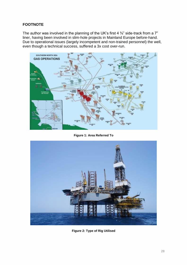
FOOTNOTE The author was involved in the planning of the UK’s first 4 ¾” side-track from a 7” liner, having been involved in slim-hole projects in Mainland Europe before-hand. Due to operational issues (largely incompetent and non-trained personnel) the well, even though a technical success, suffered a 3x cost over-run.
Figure 1: Area Referred To
Figure 2: Type of Rig Utilised
![Slim Hole Formation Tester · 2019-08-02 · Slim Hole Formation Tester The IPI Slim Hole FormationTester produces detailed evaluation of formations in boreholes as small as 3" [76mm]](https://img.pdfslide.us/doc/110x75/5f69848fb016c05be96eb3c1/slim-hole-formation-tester-2019-08-02-slim-hole-formation-tester-the-ipi-slim.jpg)