Embed Size (px)
Citation preview
The 8051 Microcontroller
Chapter 3
INSTRUCTION SET SUMMARY
2/53
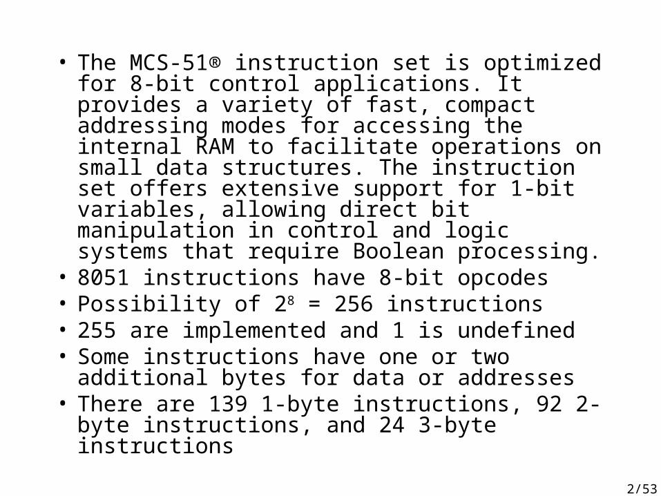
• The MCS-51® instruction set is optimized for 8-bit control applications. It provides a variety of fast, compact addressing modes for accessing the internal RAM to facilitate operations on small data structures. The instruction set offers extensive support for 1-bit variables, allowing direct bit manipulation in control and logic systems that require Boolean processing.
• 8051 instructions have 8-bit opcodes• Possibility of 28 = 256 instructions• 255 are implemented and 1 is undefined• Some instructions have one or two additional
bytes for data or addresses• There are 139 1-byte instructions, 92 2-byte
instructions, and 24 3-byte instructions
3/53
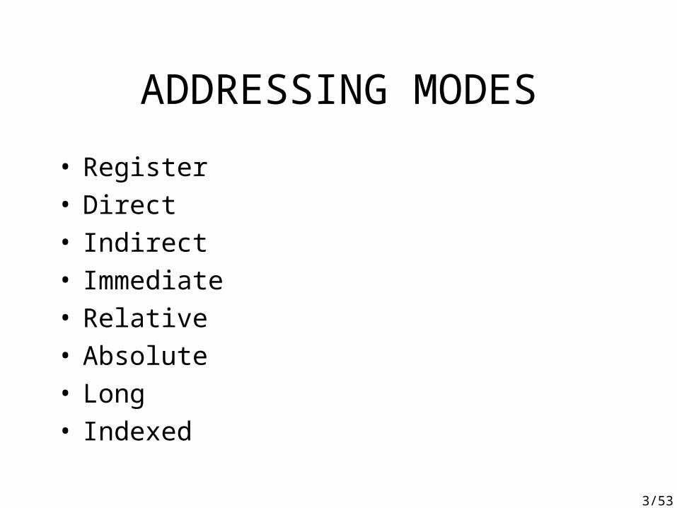
ADDRESSING MODES
• Register• Direct• Indirect• Immediate• Relative• Absolute• Long• Indexed
4/53
5/53
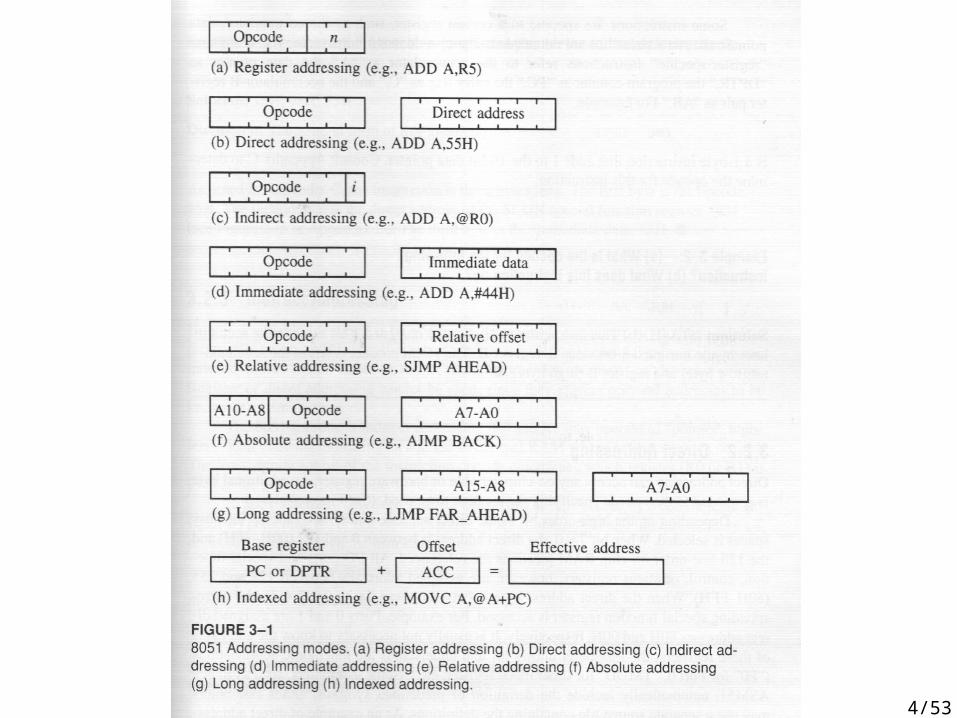
Register Addressing
• 8 "working registers," numbered R0 through R7.• Instructions using register addressing are encoded
using the three least-significant bits of the instruction opcode to specify a register within this logical address space
• Function code and operand address can be combined to form a short (1-byte) instruction.
• 8051 assembly language indicates register addressing with the symbol Rn where n is from 0 to 7.
6/53
7/53
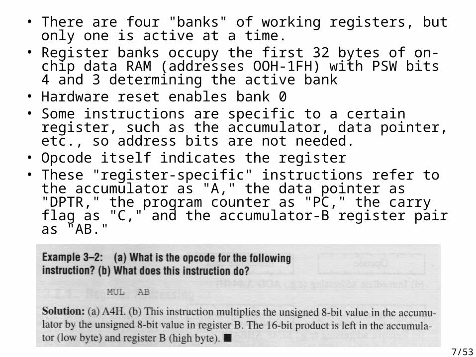
• There are four "banks" of working registers, but only one is active at a time.
• Register banks occupy the first 32 bytes of on-chip data RAM (addresses OOH-1FH) with PSW bits 4 and 3 determining the active bank
• Hardware reset enables bank 0• Some instructions are specific to a certain register, such as the
accumulator, data pointer, etc., so address bits are not needed.• Opcode itself indicates the register• These "register-specific" instructions refer to the accumulator as
"A," the data pointer as "DPTR," the program counter as "PC," the carry flag as "C," and the accumulator-B register pair as "AB."
8/53
Direct Addressing
• Can access any on-chip variable or hardware register• Additional byte is appended to the opcode specifying the location to
be used• Depending on the high-order bit of the direct address, one of two
on-chip memory spaces is selected.• When bit 7 = 0, the direct address is between 0 and 127 (00H-7FH)
and the 128 low-order on-chip RAM locations are referenced.• All I/O ports and special function, control, or status registers,
however, are assigned addresses between 128 and 255 (80H-FFH).• When bit 7 = 1, the corresponding special function register is
accessed.• It is usually not necessary to know the addresses of these registers:
the assembler allows for and understands the mnemonic abbreviations ("P0"for Port 0, "TMOD" for timer mode register, etc.).
9/53
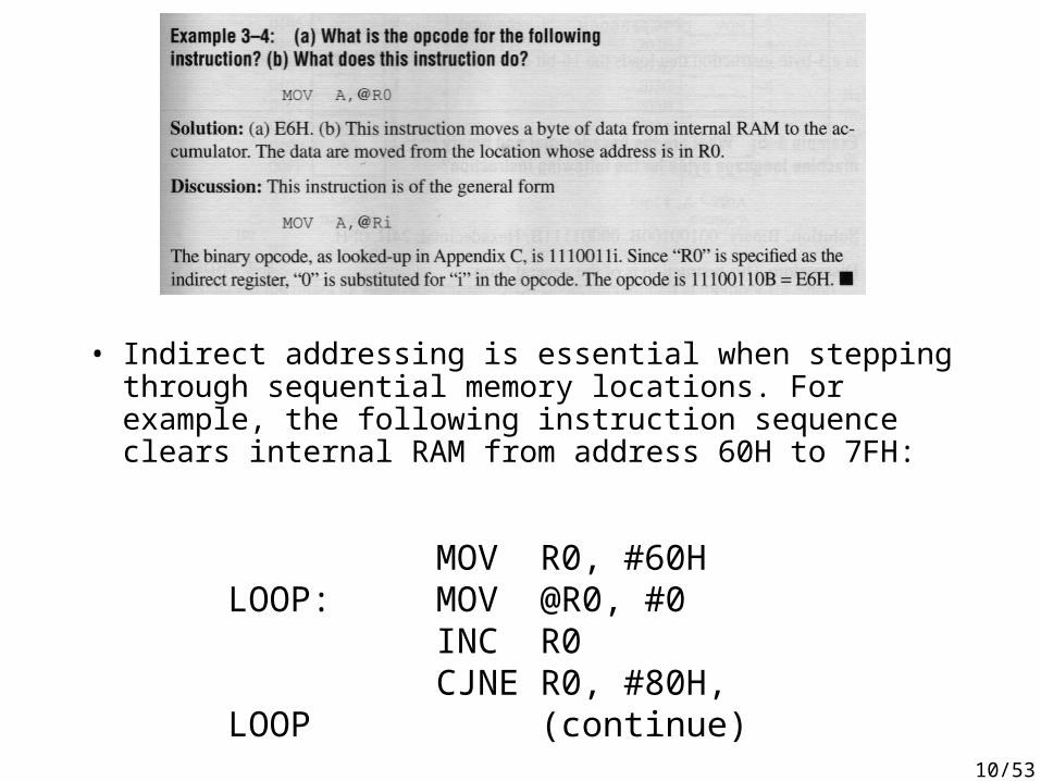
Indirect Addressing
• R0 and R1 may operate as "pointer" registers-their contents indicating an address in internal RAM
• The least-significant bit of the instruction opcode determines which register (R0 or R1) is used as the pointer.
• Indirect addressing is represented by a commercial "at" sign (@) preceding R0 or R1
10/53
• Indirect addressing is essential when stepping through sequential memory locations. For example, the following instruction sequence clears internal RAM from address 60H to 7FH:
MOV R0, #60HLOOP: MOV @R0, #0
INC R0CJNE R0, #80H, LOOP (continue)
11/53
Immediate Addressing
• When a source operand is a constant, then the constant can be incorporated into the instruction as a byte of "immediate" data.
• Additional instruction byte contains the value• Immediate operands are preceded by a number sign (#)• The operand may be a numeric constant, a symbolic
variable, or an arithmetic expression using constants, symbols, and operators.
• One exception, all instructions using immediate addressing use an 8-bit data constant for the immediate data. When initializing the data pointer, a 16-bit constant is required.
• MOV DPTR, #8000 - is a 3-byte instruction that loads the 16-bit constant 8000H into the data pointer
12/53
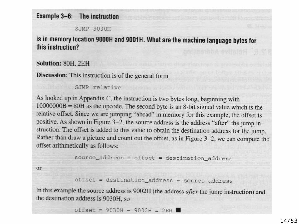
Relative Addressing
• Used only with certain jump instructions• Relative address (or offset) is an 8-bit signed value, which
is added to the program counter to form the address of the next instruction executed
• The range for jumping is -128 to +127 locations• Relative offset is appended to the instruction as an
additional byte• Prior to the addition, the program counter is incremented
to the address following the jump instruction; thus. the new address is relative to the next instruction, not the address of the jump instruction.
• Advantage - providing position-independent code • Disadvantage - jump destinations are limited in range
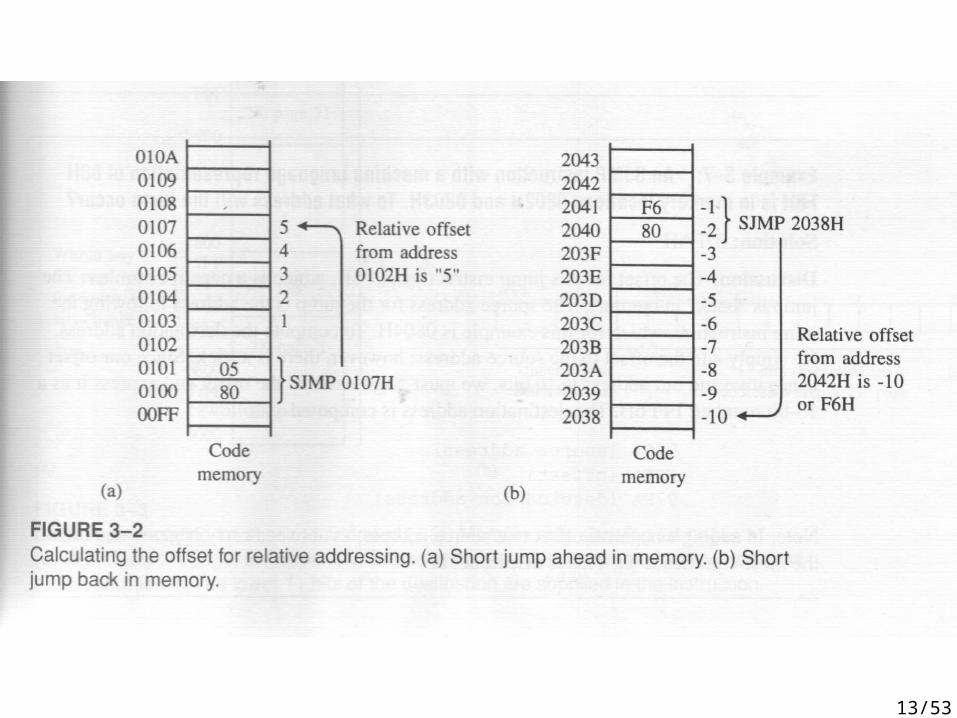
13/53
14/53
15/53
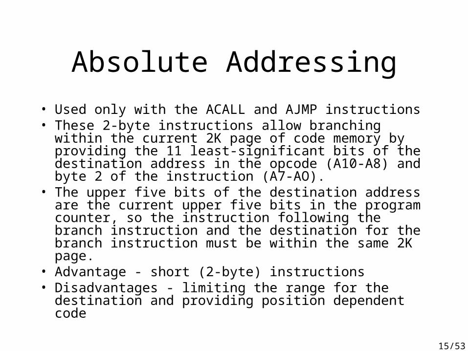
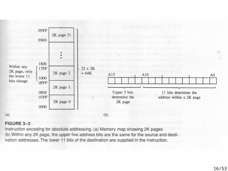
Absolute Addressing
• Used only with the ACALL and AJMP instructions• These 2-byte instructions allow branching within the
current 2K page of code memory by providing the 11 least-significant bits of the destination address in the opcode (A10-A8) and byte 2 of the instruction (A7-AO).
• The upper five bits of the destination address are the current upper five bits in the program counter, so the instruction following the branch instruction and the destination for the branch instruction must be within the same 2K page.
• Advantage - short (2-byte) instructions• Disadvantages - limiting the range for the destination and
providing position dependent code
16/53
17/53
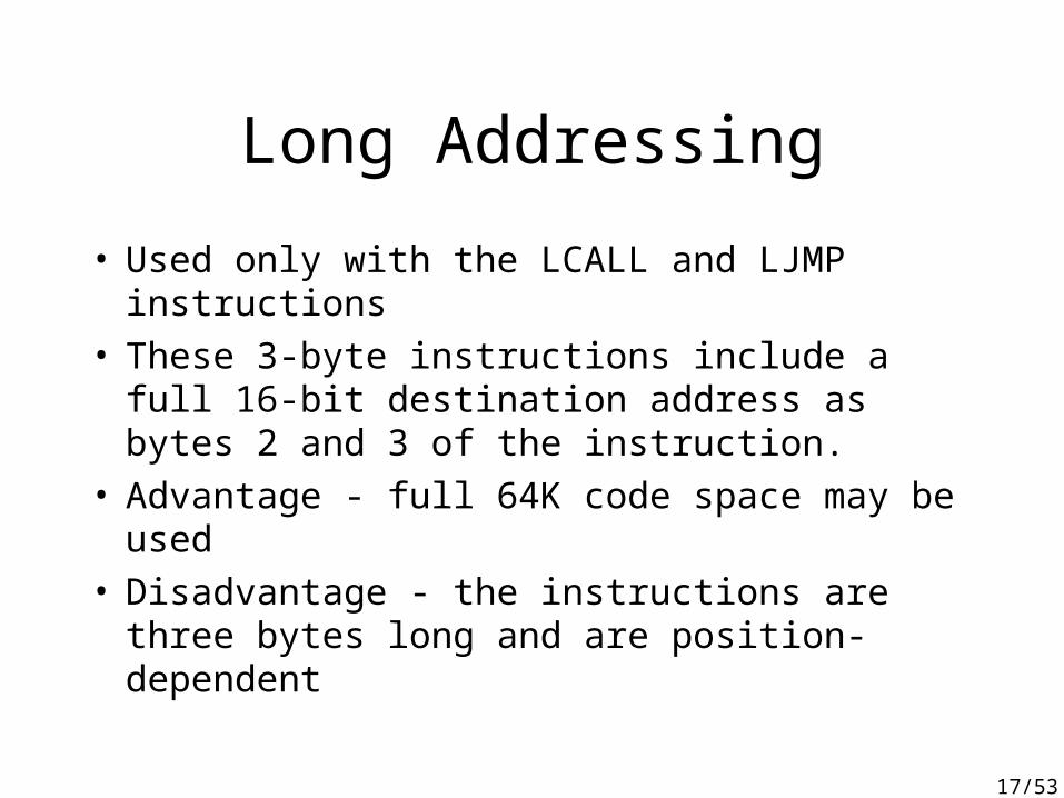
Long Addressing
• Used only with the LCALL and LJMP instructions• These 3-byte instructions include a full 16-bit
destination address as bytes 2 and 3 of the instruction.
• Advantage - full 64K code space may be used• Disadvantage - the instructions are three bytes
long and are position-dependent
18/53
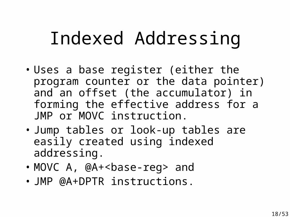
Indexed Addressing
• Uses a base register (either the program counter or the data pointer) and an offset (the accumulator) in forming the effective address for a JMP or MOVC instruction.
• Jump tables or look-up tables are easily created using indexed addressing.
• MOVC A, @A+<base-reg> and• JMP @A+DPTR instructions.
19/53
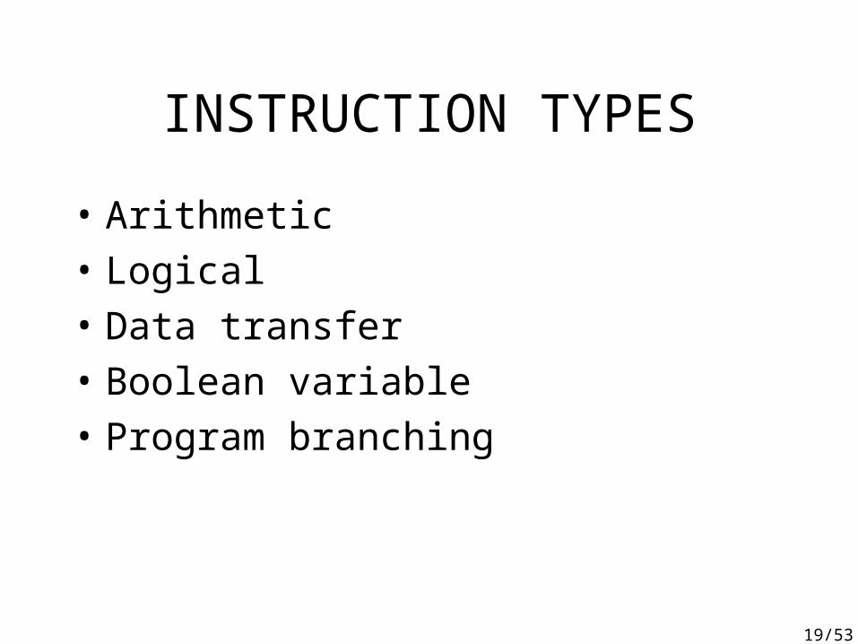
INSTRUCTION TYPES
• Arithmetic
• Logical
• Data transfer
• Boolean variable
• Program branching
20/53
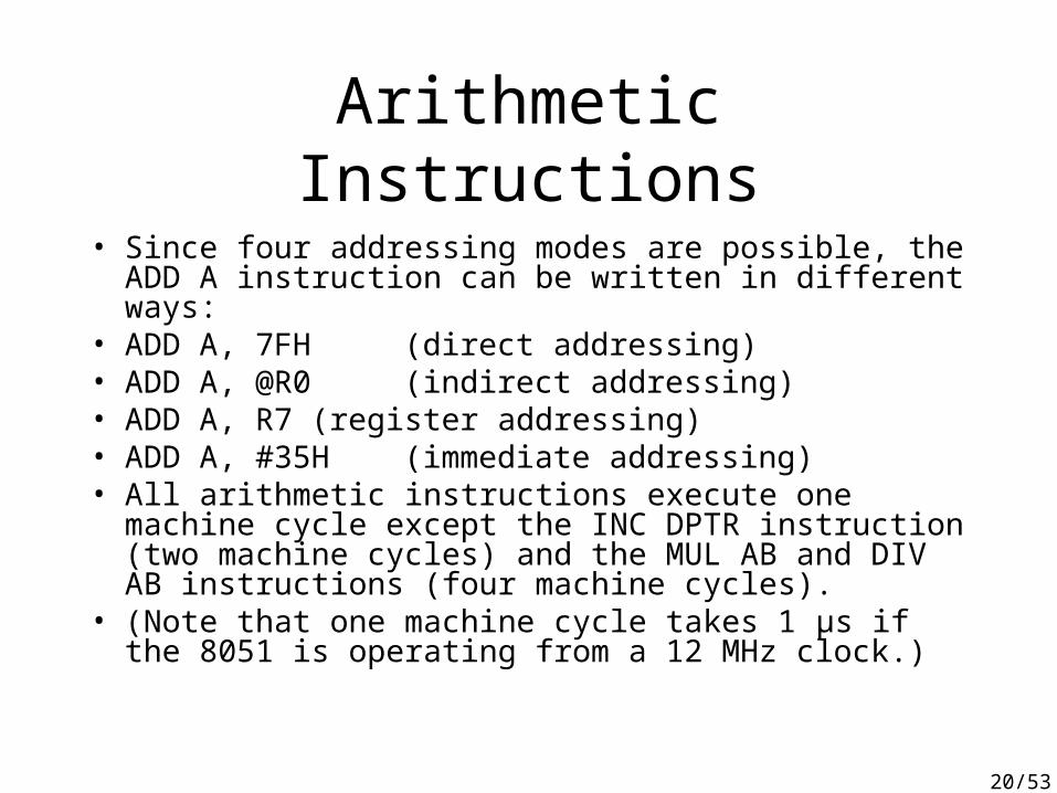
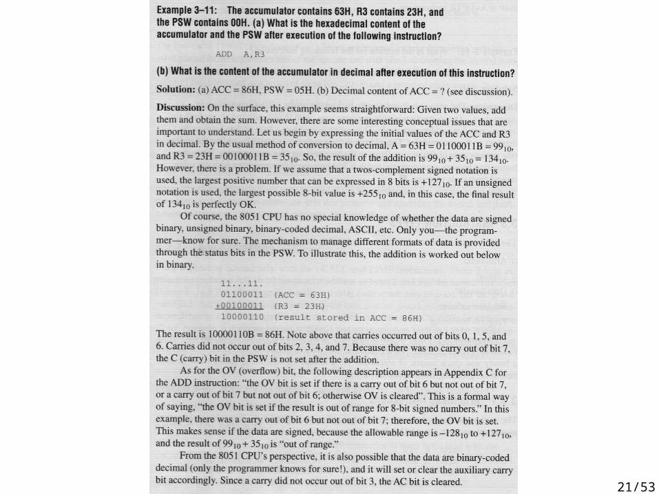
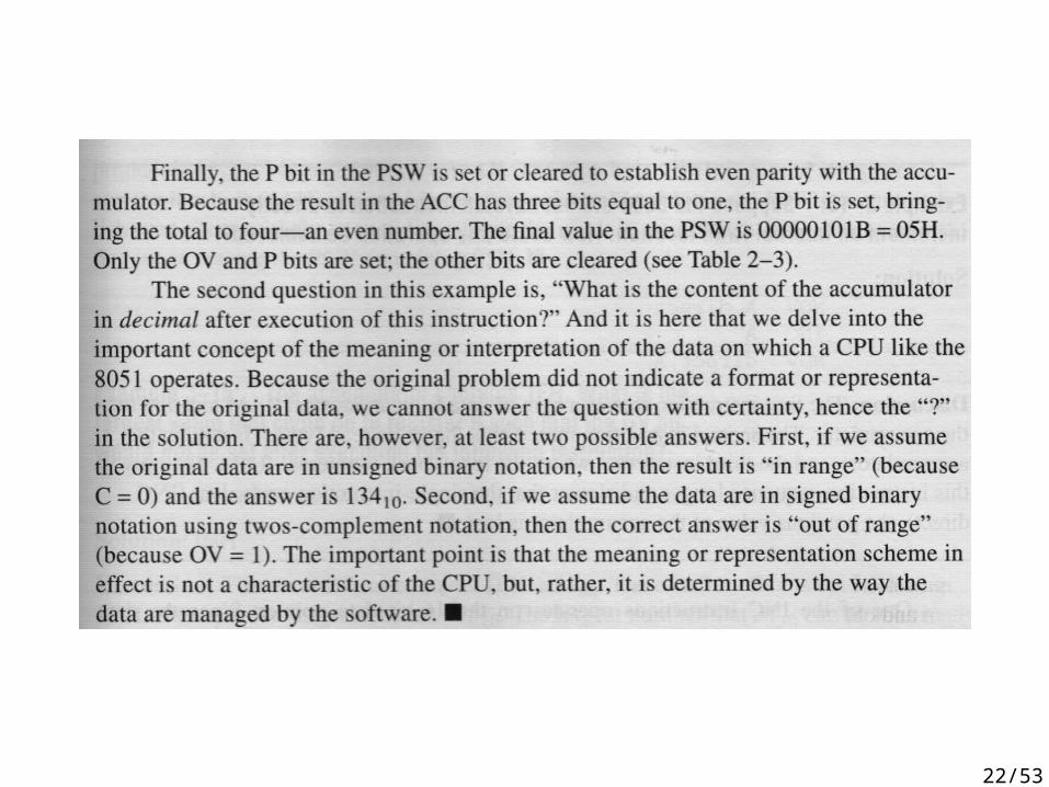
Arithmetic Instructions
• Since four addressing modes are possible, the ADD A instruction can be written in different ways:
• ADD A, 7FH (direct addressing)• ADD A, @R0 (indirect addressing)• ADD A, R7 (register addressing)• ADD A, #35H (immediate addressing)• All arithmetic instructions execute one machine cycle
except the INC DPTR instruction (two machine cycles) and the MUL AB and DIV AB instructions (four machine cycles).
• (Note that one machine cycle takes 1 μs if the 8051 is operating from a 12 MHz clock.)
21/53
22/53
23/53
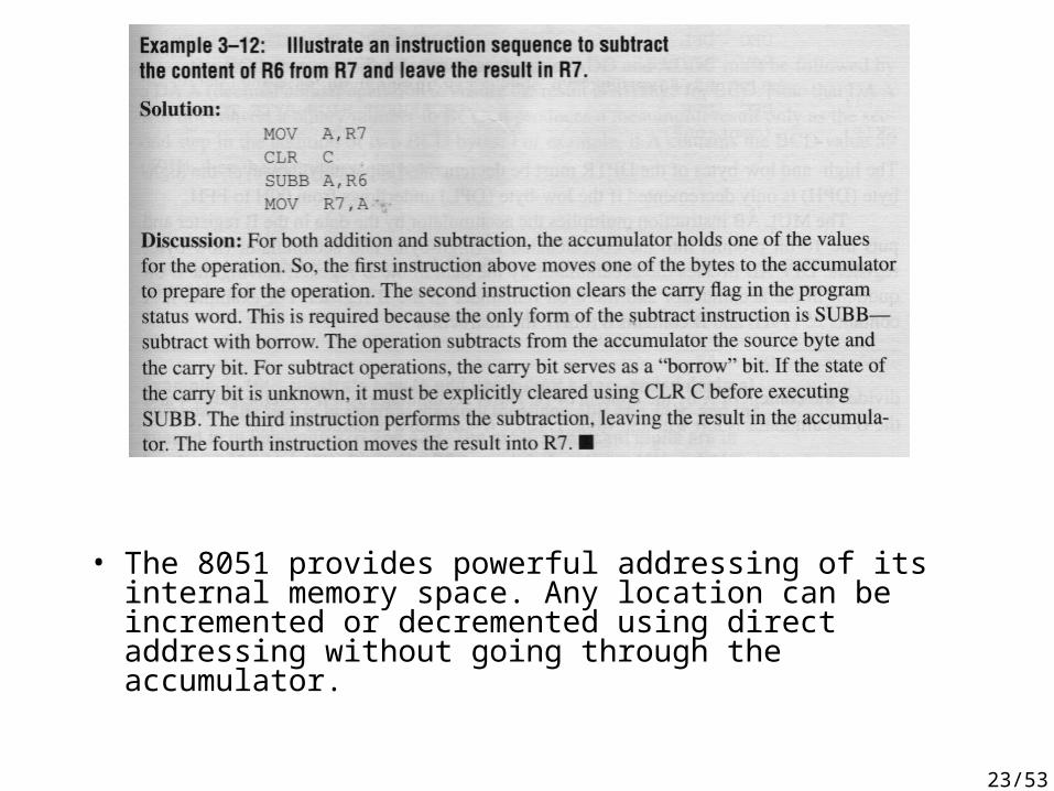
• The 8051 provides powerful addressing of its internal memory space. Any location can be incremented or decremented using direct addressing without going through the accumulator.
24/53
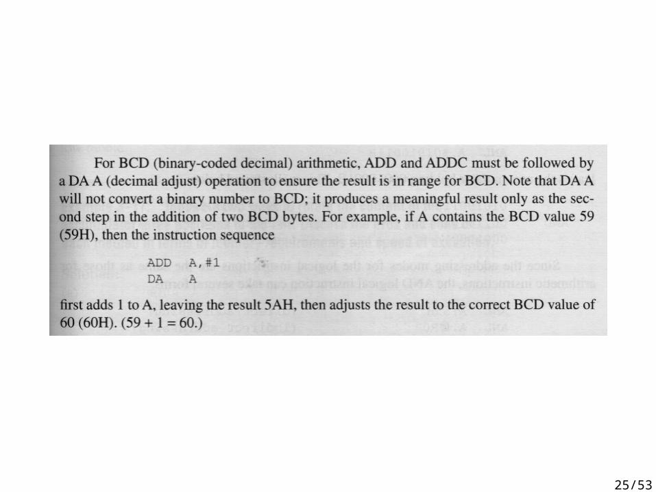
25/53
26/53
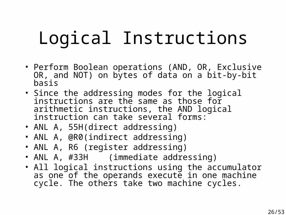
Logical Instructions
• Perform Boolean operations (AND, OR, Exclusive OR, and NOT) on bytes of data on a bit-by-bit basis
• Since the addressing modes for the logical instructions are the same as those for arithmetic instructions, the AND logical instruction can take several forms:
• ANL A, 55H (direct addressing)• ANL A, @R0 (indirect addressing)• ANL A, R6 (register addressing)• ANL A, #33H (immediate addressing)• All logical instructions using the accumulator as one of the
operands execute in one machine cycle. The others take two machine cycles.
27/53
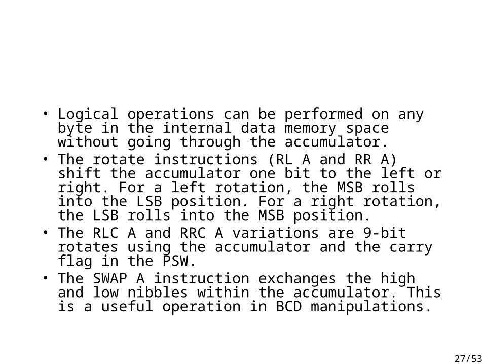
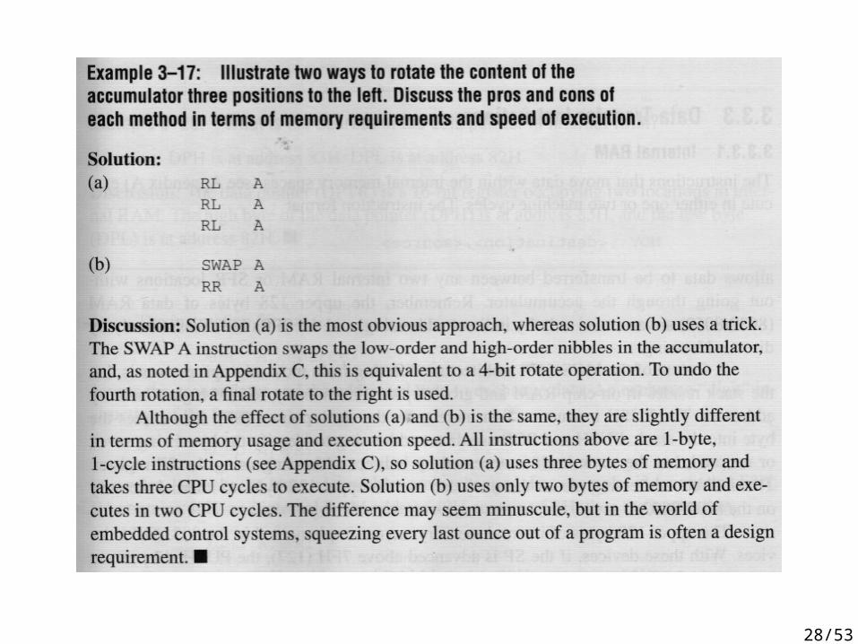
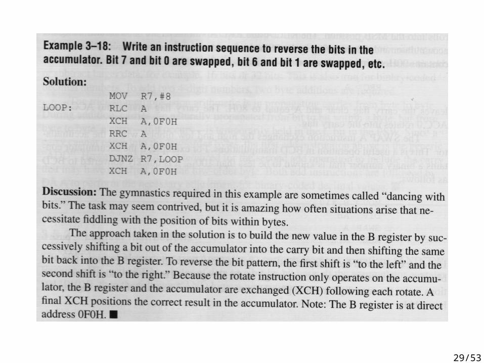
• Logical operations can be performed on any byte in the internal data memory space without going through the accumulator.
• The rotate instructions (RL A and RR A) shift the accumulator one bit to the left or right. For a left rotation, the MSB rolls into the LSB position. For a right rotation, the LSB rolls into the MSB position.
• The RLC A and RRC A variations are 9-bit rotates using the accumulator and the carry flag in the PSW.
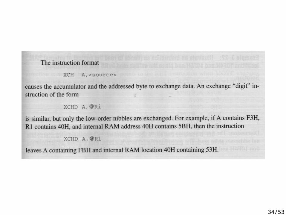
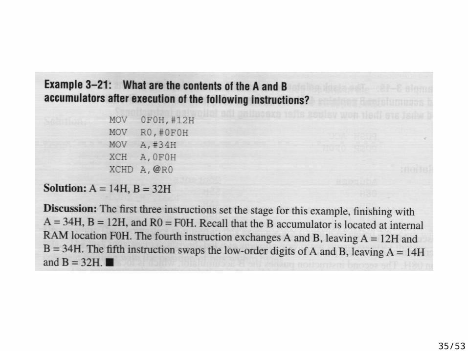
• The SWAP A instruction exchanges the high and low nibbles within the accumulator. This is a useful operation in BCD manipulations.
28/53
29/53
30/53
Data Transfer Instructions
• Internal RAM
• External RAM
• Look-Up Tables
31/53
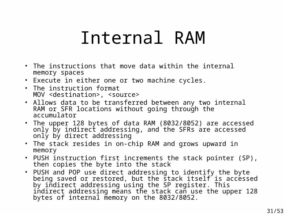
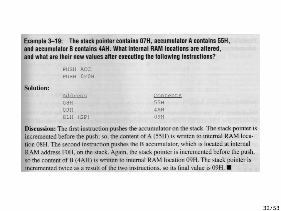
Internal RAM
• The instructions that move data within the internal memory spaces• Execute in either one or two machine cycles.• The instruction format
MOV <destination>, <source>• Allows data to be transferred between any two internal RAM or SFR
locations without going through the accumulator• The upper 128 bytes of data RAM (8032/8052) are accessed only by
indirect addressing, and the SFRs are accessed only by direct addressing
• The stack resides in on-chip RAM and grows upward in memory• PUSH instruction first increments the stack pointer (SP), then copies
the byte into the stack• PUSH and POP use direct addressing to identify the byte being saved
or restored, but the stack itself is accessed by indirect addressing using the SP register. This indirect addressing means the stack can use the upper 128 bytes of internal memory on the 8032/8052.
32/53
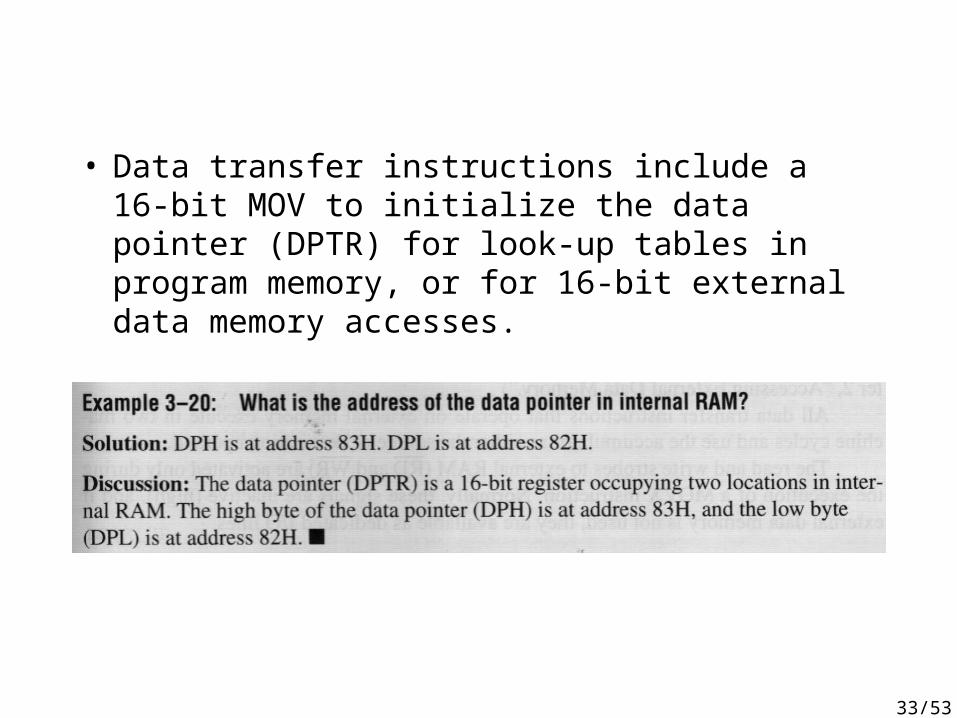
33/53
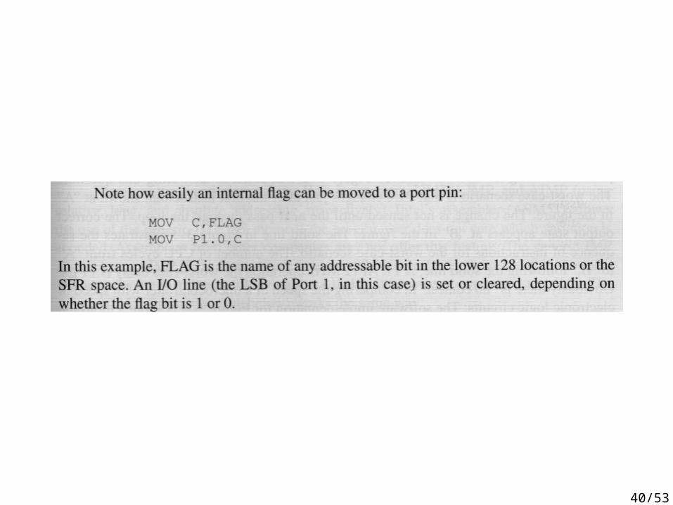
• Data transfer instructions include a 16-bit MOV to initialize the data pointer (DPTR) for look-up tables in program memory, or for 16-bit external data memory accesses.
34/53
35/53
36/53
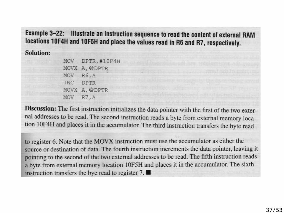
External RAM
• The data transfer instructions that move data between internal and external memory use indirect addressing.
• The indirect address is specified using a 1-byte address (@Ri, where Ri is either R0 or R1 of the selected register bank), or a 2-byte address (@DPTR).
• The disadvantage in using 16-bit addresses is that all eight bits of Port 2 are used as the high-byte of the address bus. This precludes the use of Port 2 as an I/O port. On the other hand, 8-bit addresses allow access to a few Kbytes of RAM, without sacrificing all of Port 2.
• All data transfer instructions that operate on external memory execute in two machine cycles and use the accumulator as either the source or destination operand.
• The read and write strobes to external RAM (RD and WR) are activated only during the execution of a MOVX instruction. Normally, these signals are inactive (high), and if external data memory is not used, they are available as dedicated I/O lines.
37/53
38/53
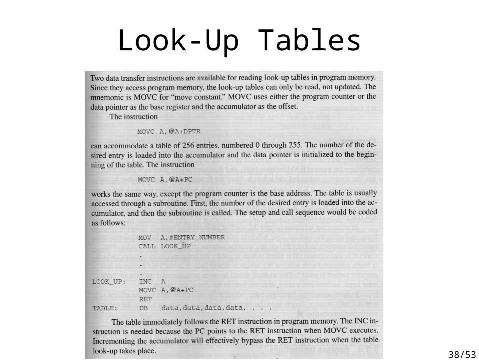
Look-Up Tables
39/53
Boolean Instructions
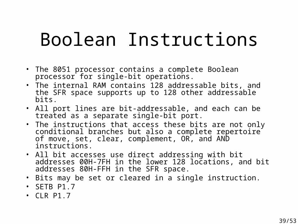
• The 8051 processor contains a complete Boolean processor for single-bit operations.
• The internal RAM contains 128 addressable bits, and the SFR space supports up to 128 other addressable bits.
• All port lines are bit-addressable, and each can be treated as a separate single-bit port.
• The instructions that access these bits are not only conditional branches but also a complete repertoire of move, set, clear, complement, OR, and AND instructions.
• All bit accesses use direct addressing with bit addresses 00H-7FH in the lower 128 locations, and bit addresses 80H-FFH in the SFR space.
• Bits may be set or cleared in a single instruction.• SETB P1.7• CLR P1.7
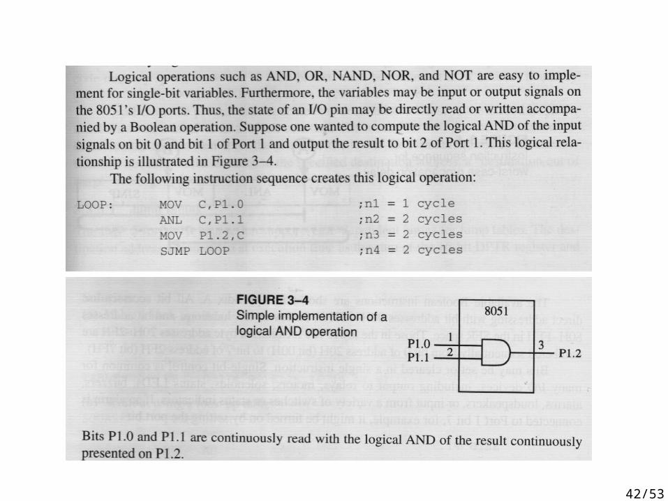
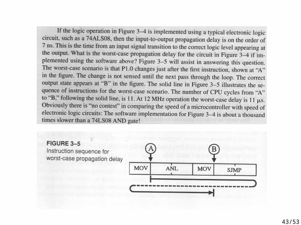
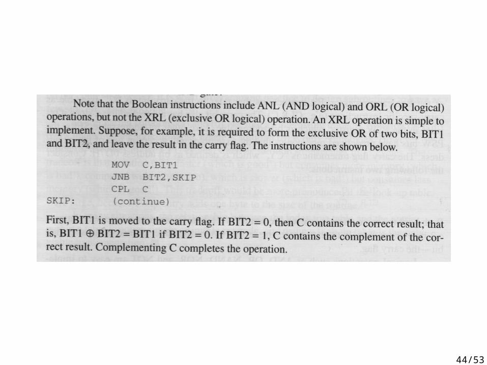
40/53
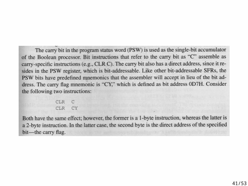
41/53
42/53
43/53
44/53
45/53
Bit Testing
• Bit-test instructions that jump if the addressed bit is set (JC, JB, JBC) or if the addressed bit is not set (JNC, JNB)
• JBC (jump if bit set then clear bit) executes the jump if the addressed bit is set, and also clears the bit; thus, a flag can be tested and cleared in a single instruction.
• All PSW bits are directly addressable (the parity bit or the general purpose flags).
46/53
Program Branching Instructions
• Numerous instructions that call and return from subroutines or branch conditionally or unconditionally
• Three variations of the JMP instruction: SJMP, LJMP, and AJMP (using relative, long, and absolute addressing, respectively)
• Intel's assembler (ASM51) allows the use of the generic JMP mnemonic
• Generic JMP assembles to AJMP if the destination contains no forward reference and is within the same 2K page (as the instruction following the AJMP) otherwise, it assembles to LJMP
• Generic CALL instruction works the same way
47/53
• SJMP instruction specifies the destination address as a relative offset• Two bytes long• The jump distance is limited to -128 to +127 bytes relative to the
address following the SJMP• LJMP instruction specifies the destination address as a 16-bit constant• Three bytes long • AJMP instruction specifies the destination address as an 11-bit
constant• Two bytes long• Destination must be within the same 2K block as the instruction
following the AJMP• Since there is 64K of code memory space. there are 32 such blocks,
each beginning at a 2K address boundary• Programmer specifies the destination address as a label or as a 16-bit
constant.• If the format required by the instruction will not support the distance
to the specified destination address, a "destination out of range" message is given.
48/53
Jump Tables• The JMP @A+DPTR instruction supports case-dependent jumps for jump tables. The
destination address is computed at execution time as the sum of the 16-bit DPTR register and the accumulator. Typically, the DPTR is loaded with the address of a jump table, and the accumulator acts as an index. If, for example, five "cases" are desired, a value from 0 through 4 is loaded into the accumulator and a jump to the appropriate case is performed as follows:
MOV DPTR, #JUMPTABLEMOV A, #INDEX_NUMBERRL AJMP @A+DPTR
• The RL A instruction above converts the index number (0 through 4) to an even number in the range 0 through 8 because each entry in the jump table is a 2-byte address:
JUMP_TABLE: AJMP CASE0AJMP CASE1AJMP CASE2AJMP CASE3
49/53
Subroutines and Interrupts
• Two variations of the CALL instruction: ACALL and LCALL, using absolute and long addressing, respectively.
• Generic CALL mnemonic may be used with Intel's assembler
• Either instruction pushes the content of the program counter on the stack and loads the program counter with the address specified in the instruction
• PC will contain the address of the instruction following the CALL instruction when it gets pushed on the stack
• PC is pushed on the stack low-byte first, high-byte second.• LCALL and ACALL instructions have the same
restrictions on the destination address as the LJMP and AJMP instructions just discussed.
50/53
• Subroutines should end with an RET instruction, which returns execution to the instruction following the CALL.
• It simply "pops" the last two bytes off the stack and places them in the program counter.
• RETI is used to return from an interrupt service routine (ISR).
• RETI signals the interrupt control system that the interrupt in progress is done.
51/53
Conditional Jumps
• The 8051 offers a variety of conditional jump instructions.• All of these specify the destination address using relative addressing
and so are limited to a jump distance of -128 to +127 bytes from the instruction following the conditional jump instruction.
• There is no 0-bit in the PSW. The JZ and JNZ instructions test the accumulator data for that condition.
• DJNZ instruction (decrement and jump if not zero) is for loop control.MOV R7, #10
LOOP: (begin loop)
(end loop)DJNZ R7, LOOP(continue)
52/53
• The CJNE instruction (compare and jump if not equal) is also used for loop control. Two bytes are specified in the operand field of the instruction, and the jump is executed only if the two bytes are not equal.
CJNE A, #03H, SKIP
SJMP TERMINATE
SKIP: (continue)• Jump occurs only if A != CONTROL-C, a skip is
used to bypass the terminating jump instruction except when the desired code is read.
53/53
• Another application of this instruction is in "greater than" or "less than" comparisons. The two bytes in the operand field are taken as unsigned integers. If the first is less than the second, the carry flag is set. If the first is greater than or equal to the second, the carry flag is cleared.
CJNE A, #20H, $+3JNC BIG
• The jump destination for CJNE is specified as "$+3." The dollar sign ($) is a special assembler symbol representing the address of the current instruction. Since CJNE is a 3-byte instruction, "$+3" is the address of the next instruction, JNC. In other words, the CJNE instruction follows through to the JNC instruction regardless of the result of the compare. The sole purpose of the compare is to set or clear the carry flag.


![Section 1 8051 Microcontroller Instruction Set - UNESP 8051/Atmel8051... · Section 1 8051 Microcontroller Instruction Set ... port, control register, ... (P6) [2B, 2C] AJMP (P7)](https://img.pdfslide.us/doc/110x75/5b5ae8c47f8b9a905c8ceee9/section-1-8051-microcontroller-instruction-set-8051atmel8051-section-1.jpg)