Embed Size (px)
Citation preview
8/6/2019 8051 Microcontroller –
http://slidepdf.com/reader/full/8051-microcontroller- 1/20
Pari vallal Kannan
Center for Integrated Circuits and Systems
University of Texas at Dallas
8051 Microcontroller –Architecture, Intro to Assembly
Programming
EE4380 Fall 2002
Class 2
8/6/2019 8051 Microcontroller –
http://slidepdf.com/reader/full/8051-microcontroller- 2/20
29-Aug-02 2
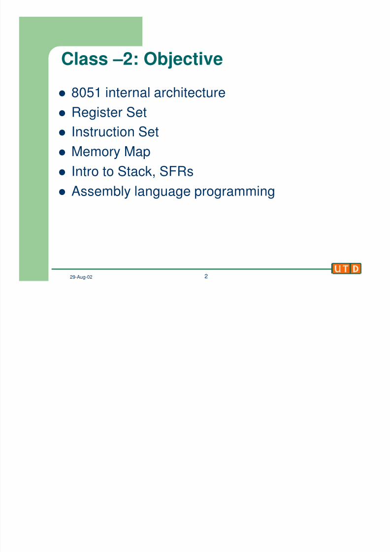
Class –2: Objectivel 8051 internal architecture
l Register Set
l
Instruction Setl Memory Map
l Intro to Stack, SFRs
l Assembly language programming
8/6/2019 8051 Microcontroller –
http://slidepdf.com/reader/full/8051-microcontroller- 3/20
29-Aug-02 3
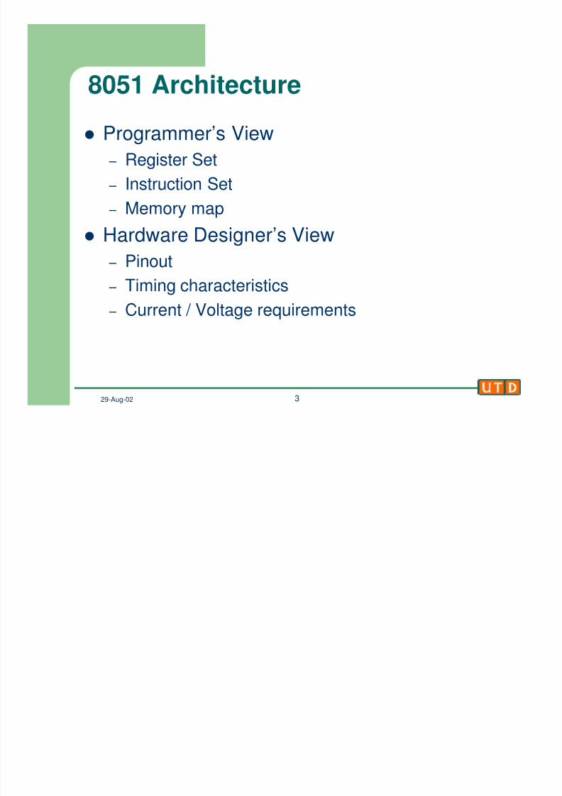
8051 Architecturel Programmer’s View
– Register Set
– Instruction Set
– Memory map
l Hardware Designer’s View
– Pinout
–
Timing characteristics – Current / Voltage requirements
8/6/2019 8051 Microcontroller –
http://slidepdf.com/reader/full/8051-microcontroller- 4/20
29-Aug-02 4
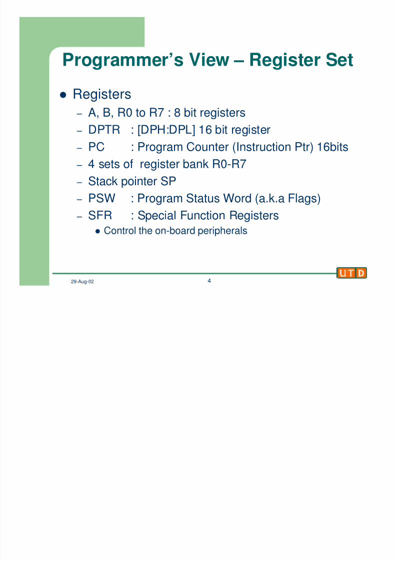
Programmer’s View – Register Setl Registers
– A, B, R0 to R7 : 8 bit registers
– DPTR : [DPH:DPL] 16 bit register
– PC : Program Counter (Instruction Ptr) 16bits
– 4 sets of register bank R0-R7
– Stack pointer SP
– PSW : Program Status Word (a.k.a Flags)
– SFR : Special Function Registers
l Control the on-board peripherals
8/6/2019 8051 Microcontroller –
http://slidepdf.com/reader/full/8051-microcontroller- 5/20
29-Aug-02 5
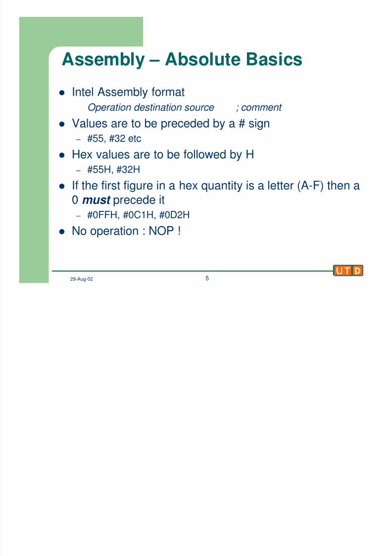
Assembly – Absolute Basicsl Intel Assembly format
Operation destination source ; comment
l Values are to be preceded by a # sign
– #55, #32 etc
l Hex values are to be followed by H
– #55H, #32H
l If the first figure in a hex quantity is a letter (A-F) then a
0must
precede it – #0FFH, #0C1H, #0D2H
l No operation : NOP !
8/6/2019 8051 Microcontroller –
http://slidepdf.com/reader/full/8051-microcontroller- 6/20
29-Aug-02 6
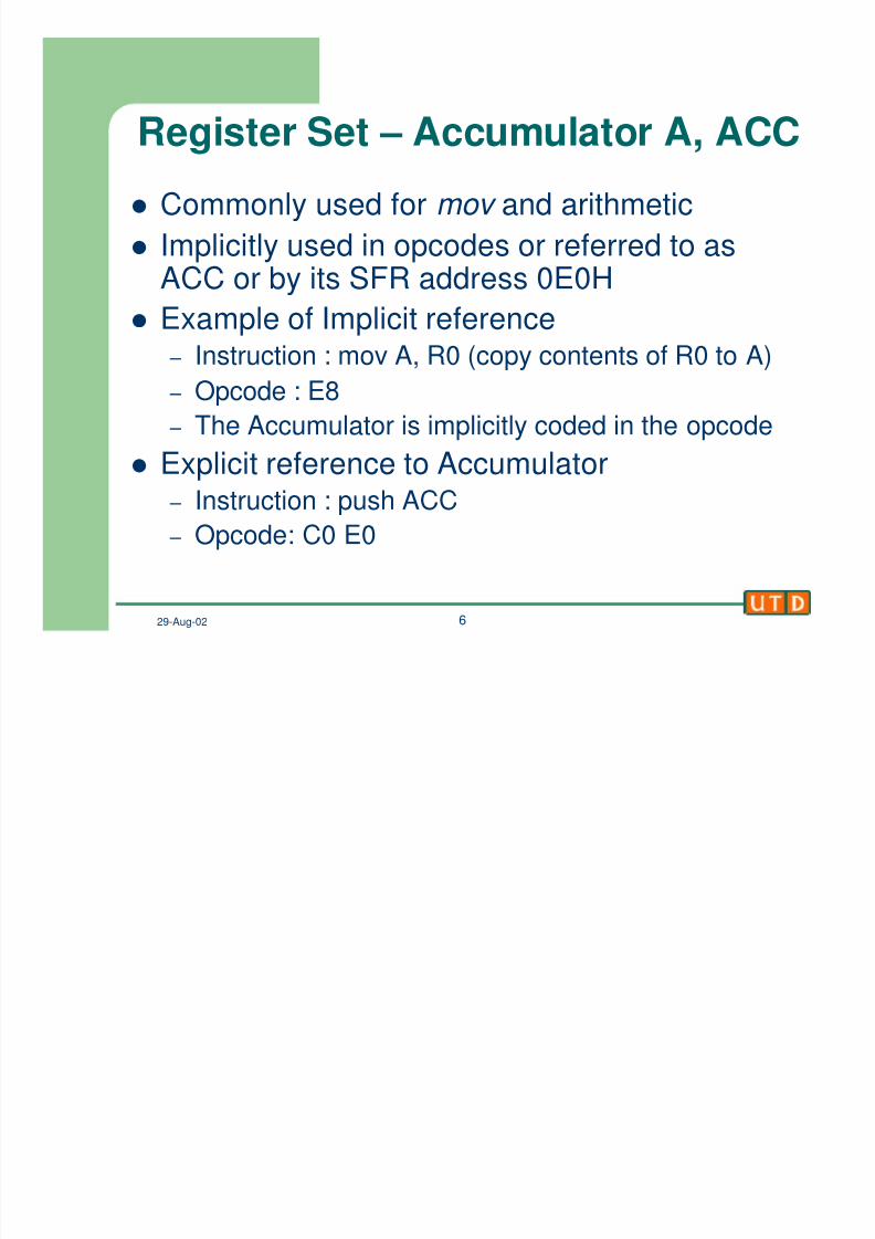
Register Set – Accumulator A, ACCl Commonly used for mov and arithmetic
l Implicitly used in opcodes or referred to asACC or by its SFR address 0E0H
l Example of Implicit reference – Instruction : mov A, R0 (copy contents of R0 to A)
– Opcode : E8
– The Accumulator is implicitly coded in the opcode
l Explicit reference to Accumulator – Instruction : push ACC
– Opcode: C0 E0
8/6/2019 8051 Microcontroller –
http://slidepdf.com/reader/full/8051-microcontroller- 7/20
29-Aug-02 7
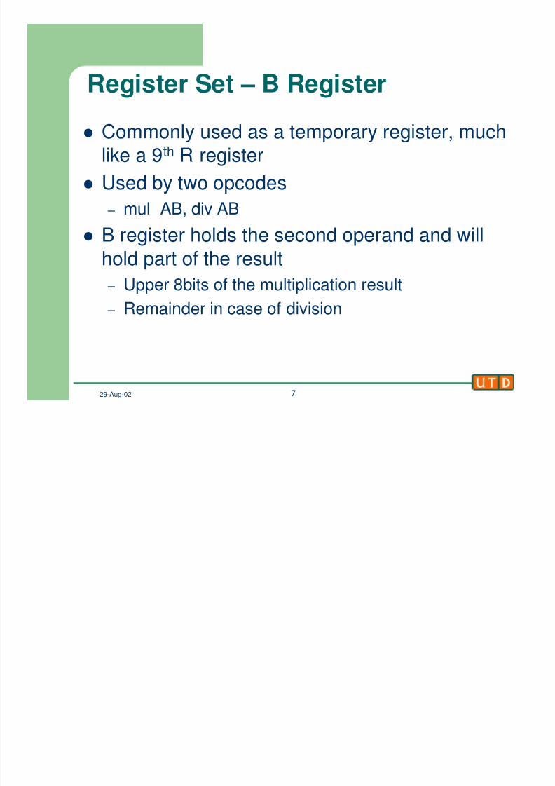
Register Set – B Registerl Commonly used as a temporary register, much
like a 9th R register
l Used by two opcodes
– mul AB, div AB
l B register holds the second operand and will
hold part of the result
– Upper 8bits of the multiplication result – Remainder in case of division
8/6/2019 8051 Microcontroller –
http://slidepdf.com/reader/full/8051-microcontroller- 8/20
29-Aug-02 8
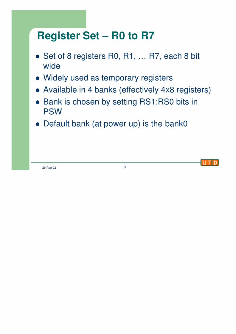
Register Set – R0 to R7l Set of 8 registers R0, R1, … R7, each 8 bit
wide
l Widely used as temporary registers
l Available in 4 banks (effectively 4x8 registers)
l Bank is chosen by setting RS1:RS0 bits in
PSW
l Default bank (at power up) is the bank0
8/6/2019 8051 Microcontroller –
http://slidepdf.com/reader/full/8051-microcontroller- 9/20
29-Aug-02 9
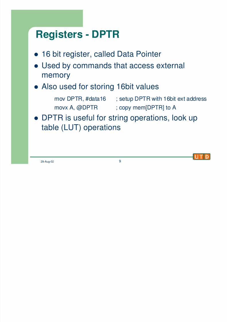
Registers - DPTRl 16 bit register, called Data Pointer
l Used by commands that access externalmemory
l Also used for storing 16bit values
mov DPTR, #data16 ; setup DPTR with 16bit ext address
movx A, @DPTR ; copy mem[DPTR] to A
l DPTR is useful for string operations, look uptable (LUT) operations

8/6/2019 8051 Microcontroller –
http://slidepdf.com/reader/full/8051-microcontroller- 10/20
29-Aug-02 10
Registers - PCl PC is the program counter
l Referred to as the Instruction Pointer (IP) in other
microprocessors
l PC points to the next program instruction always
l After fetching an instruction (1 or multi byte), PC isautomatically incremented to point to the nextinstruction
l
Cannot directly manipulate PC (exceptions JMPstatements)
l Cannot directly read contents of PC (tricks available)
8/6/2019 8051 Microcontroller –
http://slidepdf.com/reader/full/8051-microcontroller- 11/20
29-Aug-02 11
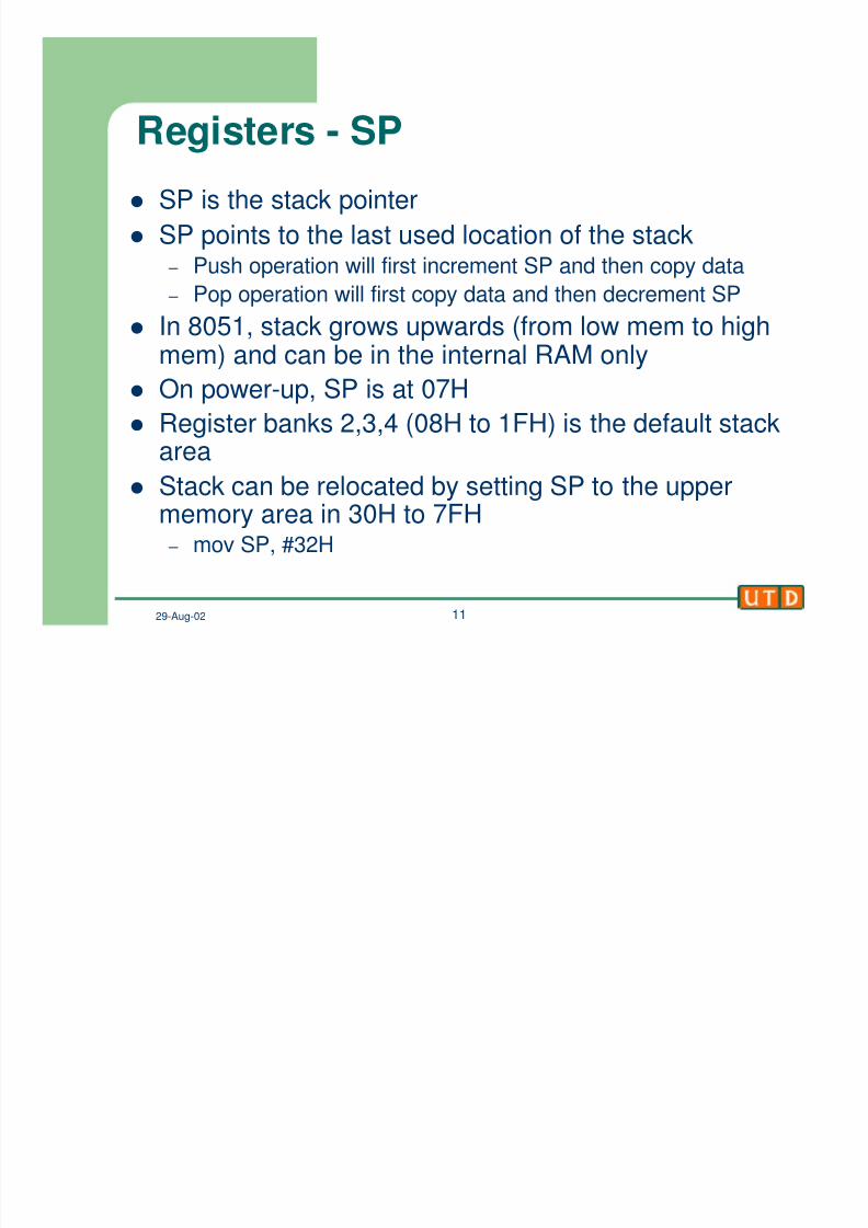
Registers - SPl SP is the stack pointer
l SP points to the last used location of the stack – Push operation will first increment SP and then copy data
– Pop operation will first copy data and then decrement SPl In 8051, stack grows upwards (from low mem to high
mem) and can be in the internal RAM only
l On power-up, SP is at 07H
l Register banks 2,3,4 (08H to 1FH) is the default stack
areal Stack can be relocated by setting SP to the upper
memory area in 30H to 7FH – mov SP, #32H
8/6/2019 8051 Microcontroller –
http://slidepdf.com/reader/full/8051-microcontroller- 12/20
29-Aug-02 12
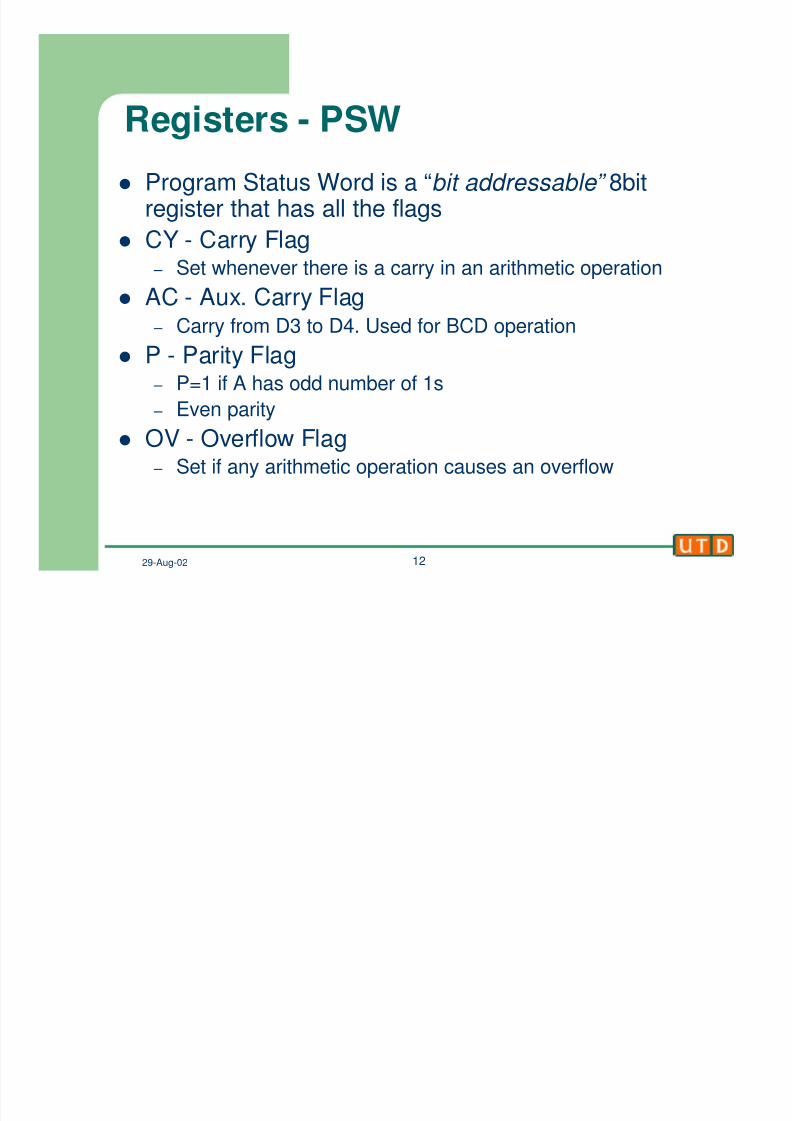
Registers - PSW
l Program Status Word is a “bit addressable” 8bitregister that has all the flags
l CY - Carry Flag
– Set whenever there is a carry in an arithmetic operationl AC - Aux. Carry Flag
– Carry from D3 to D4. Used for BCD operation
l P - Parity Flag – P=1 if A has odd number of 1s
– Even parityl OV - Overflow Flag
– Set if any arithmetic operation causes an overflow
8/6/2019 8051 Microcontroller –
http://slidepdf.com/reader/full/8051-microcontroller- 13/20
29-Aug-02 13
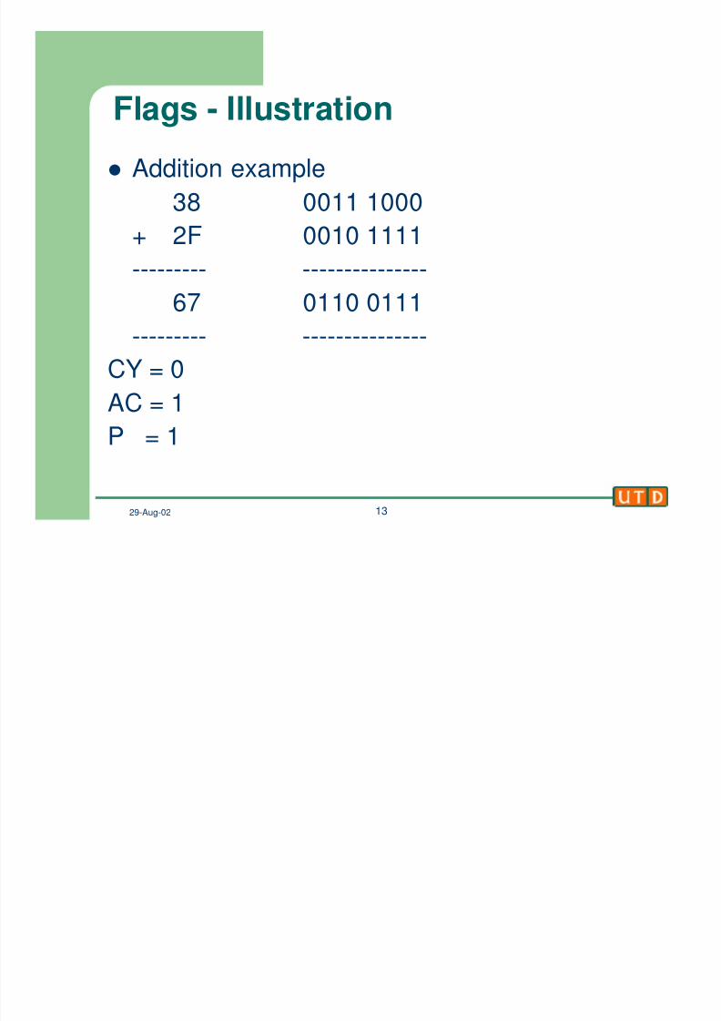
Flags - Illustration
l Addition example
38 0011 1000
+ 2F 0010 1111
--------- ---------------
67 0110 0111
--------- ---------------
CY = 0AC = 1
P = 1
8/6/2019 8051 Microcontroller –
http://slidepdf.com/reader/full/8051-microcontroller- 14/20
29-Aug-02 14
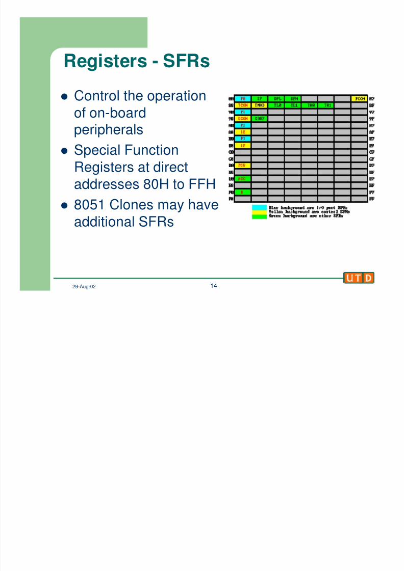
Registers - SFRs
l Control the operation
of on-boardperipherals
l Special Function
Registers at direct
addresses 80H to FFH
l
8051 Clones may haveadditional SFRs
8/6/2019 8051 Microcontroller –
http://slidepdf.com/reader/full/8051-microcontroller- 15/20
29-Aug-02 15
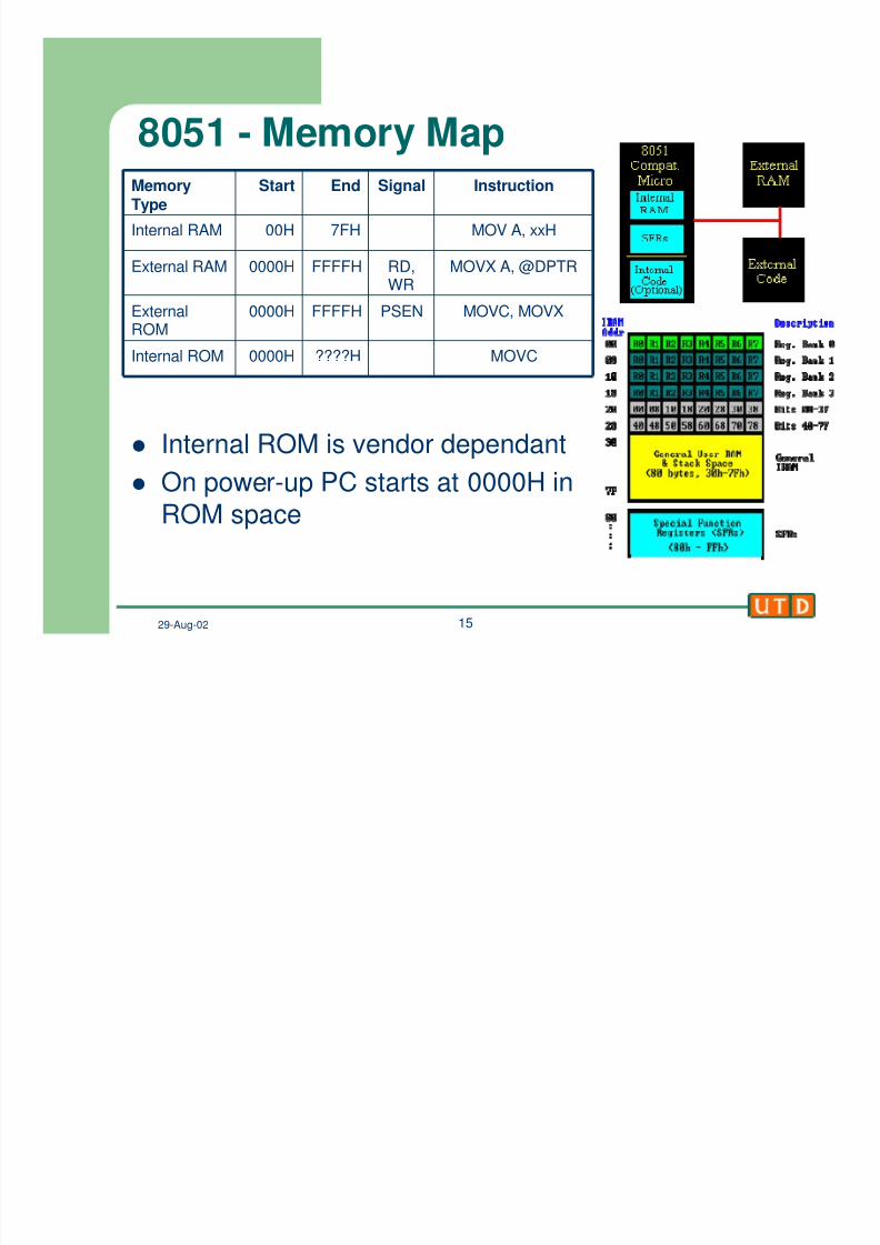
8051 - Memory Map
l Internal ROM is vendor dependant
l On power-up PC starts at 0000H in
ROM space
MOVC
MOVC, MOVX
MOVX A, @DPTR
MOV A, xxH
InstructionSignalEndStartMemoryType
????H0000HInternal ROM
PSENFFFFH0000HExternalROM
RD,WR
FFFFH0000HExternal RAM
7FH00HInternal RAM
8/6/2019 8051 Microcontroller –
http://slidepdf.com/reader/full/8051-microcontroller- 16/20
29-Aug-02 16
8051 – Instruction Set
l Data Transfer – Move/Copy data from one location to another
– mov, movc, movx, push, pop, xch, xchd
l Logical – Perform logic operations on data – anl, orl, xrl, clr, cpl, rl, rlc, rr, rrc, swap
l Arithmetic – Perform arithmetic operations on data
– add, addc, subb, inc, dec, mul, div
l Program control – Control the program flow (jumps, subroutine calls)
– jmp, ajmp, ljmp, sjmp, jc, jnc, jb, jnb, jbc, jz, jnz, acall, lcall,cjne, djnz, ret, reti
l NOP
8/6/2019 8051 Microcontroller –
http://slidepdf.com/reader/full/8051-microcontroller- 17/20
29-Aug-02 17
8051 Assembly Introduction
l Assembly statement structure[label:] opcode [operands] [;comment]
l Example
start: mov A, #D0H ;code starts herel Assembler directives
– ORG xxxxH : origin, start assembling at xxxxH
– EQU : define a constant
l count EQU 25
– DB : define byte, defines data
l DATA1: DB 28
l DATA2: DB “hello world”
– END : end of assembly file
8/6/2019 8051 Microcontroller –
http://slidepdf.com/reader/full/8051-microcontroller- 18/20
29-Aug-02 18
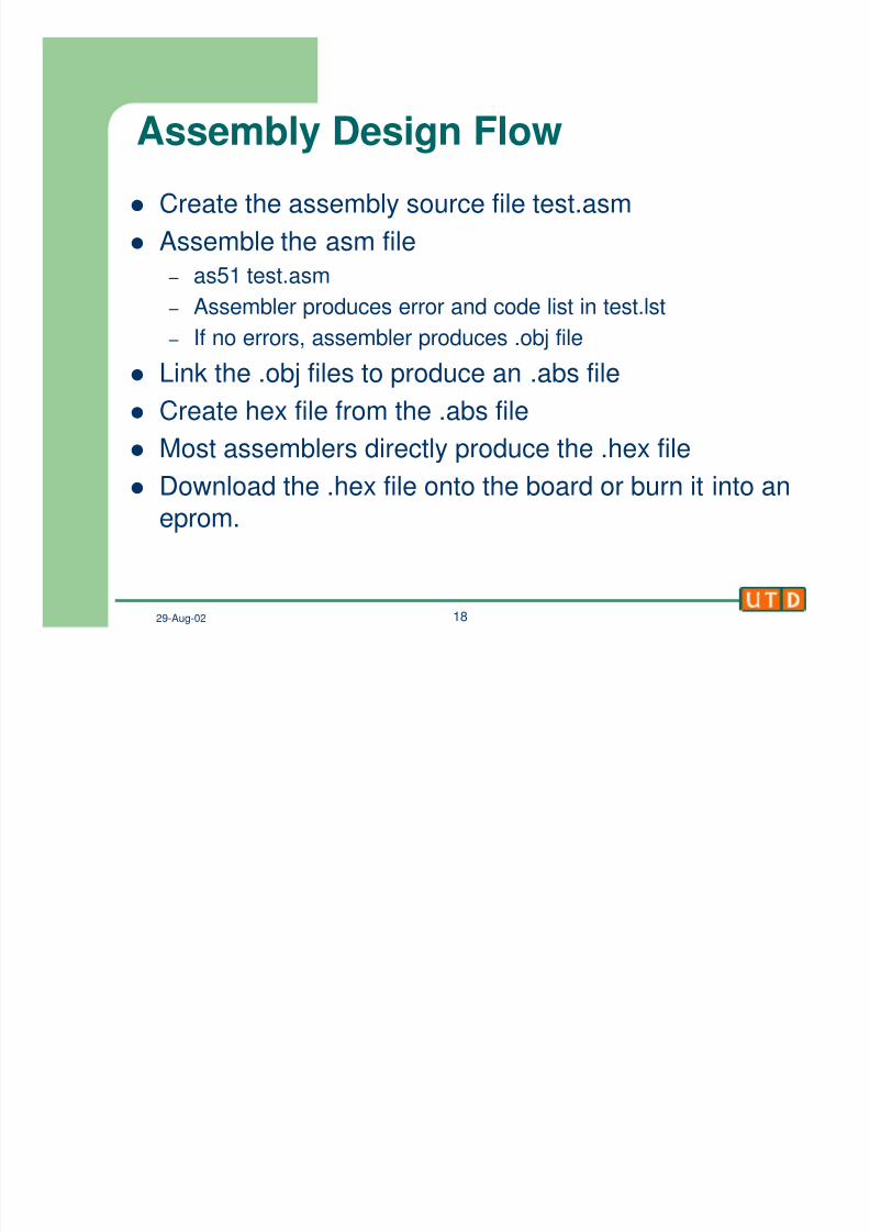
Assembly Design Flow
l Create the assembly source file test.asm
l Assemble the asm file
– as51 test.asm
– Assembler produces error and code list in test.lst – If no errors, assembler produces .obj file
l Link the .obj files to produce an .abs file
l Create hex file from the .abs file
l
Most assemblers directly produce the .hex filel Download the .hex file onto the board or burn it into an
eprom.
8/6/2019 8051 Microcontroller –
http://slidepdf.com/reader/full/8051-microcontroller- 19/20
29-Aug-02 19
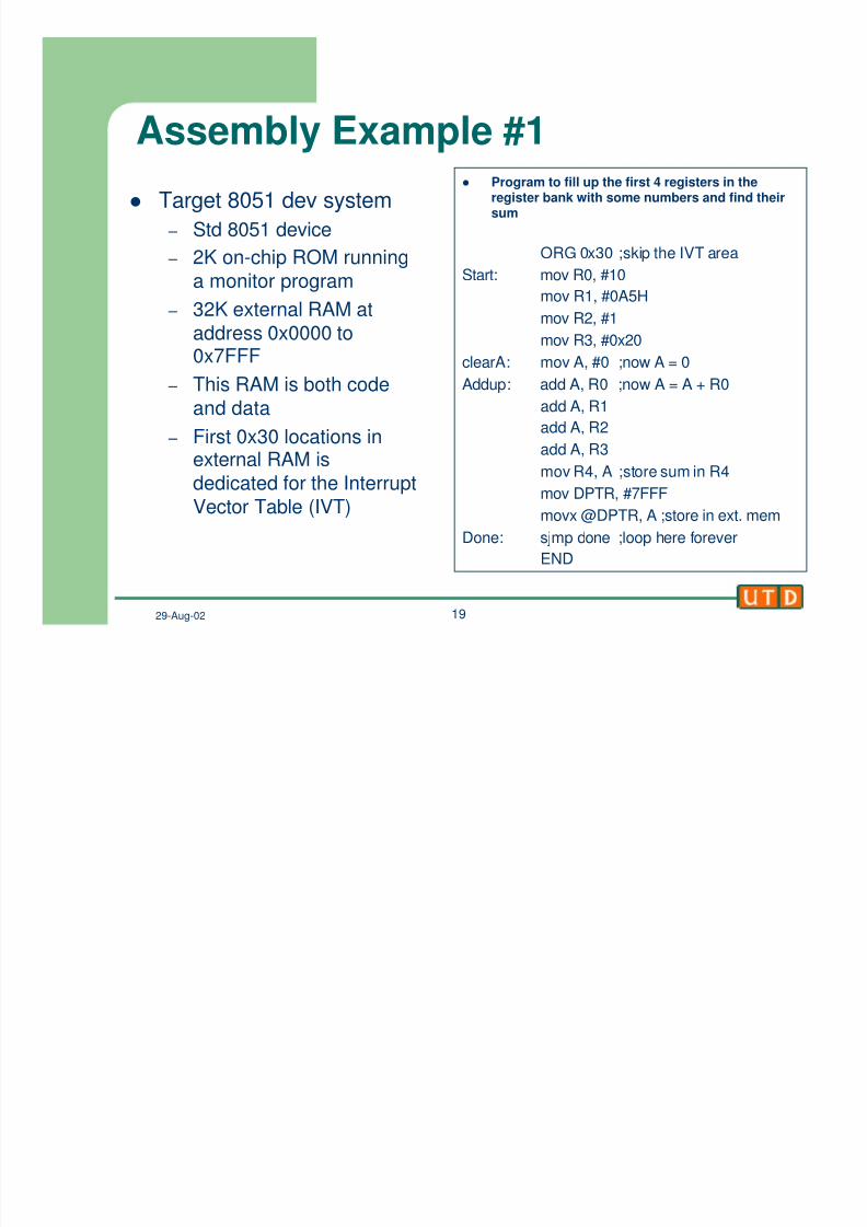
Assembly Example #1
l Target 8051 dev system
– Std 8051 device
– 2K on-chip ROM running
a monitor program
– 32K external RAM ataddress 0x0000 to0x7FFF
– This RAM is both code
and data
– First 0x30 locations in
external RAM isdedicated for the Interrupt
Vector Table (IVT)
l Program to fill up the first 4 registers in theregister bank with some numbers and find theirsum
ORG 0x30 ;skip the IVT area
Start: mov R0, #10
mov R1, #0A5H
mov R2, #1
mov R3, #0x20
clearA: mov A, #0 ;now A = 0
Addup: add A, R0 ;now A = A + R0
add A, R1
add A, R2
add A, R3mov R4, A ;store sum in R4
mov DPTR, #7FFF
movx @DPTR, A ;store in ext. mem
Done: sjmp done ;loop here forever
END
8/6/2019 8051 Microcontroller –
http://slidepdf.com/reader/full/8051-microcontroller- 20/20
29-Aug-02 20
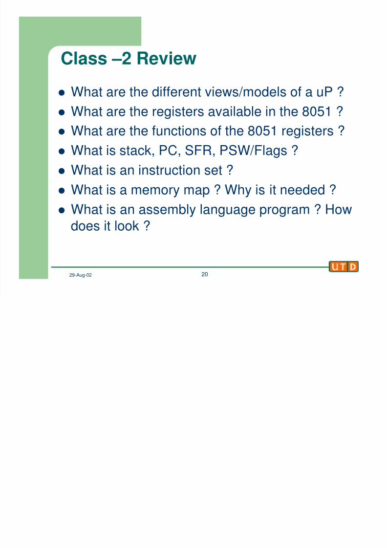
Class –2 Review
l What are the different views/models of a uP ?
l What are the registers available in the 8051 ?
l
What are the functions of the 8051 registers ?l What is stack, PC, SFR, PSW/Flags ?
l What is an instruction set ?
l What is a memory map ? Why is it needed ?
l What is an assembly language program ? How
does it look ?