Embed Size (px)
Citation preview

Localization inside Tunnels Using Machine Vision
Y.M. Hsieha and Y.C. Liaoa
aDepartment of Construction Engineering,
National Taiwan University of Science and Technology, Taiwan E-mail: [email protected]
Abstract -
Localization (position tracking) inside tunnels is difficult. GPS signal is not available inside tunnels, and installation of wireless access points is expensive. In this work, we propose the use machine vision for localization in tunnels. The advantage for such approach is that it requires no installation of any infrastructure, needed with radio triangulation approach. Prior researches have shown that machine vision can successfully identify positions in both outdoor and indoor environments. However, such application has never been tried inside tunnels. In this paper, we present our work on developing appropriate algorithms for localization in tunnels. One potential application for localization in tunnels is to help tunnel maintainers acquire accurate location information in tunnels when they do tunnel inspections and maintenances.
Keywords - Localization; machine vision; evaluation; tunnel
1 Introduction
Tunnels need to be inspected, monitored, and maintained during their lifetime. Without proper inspection and maintenance, accidents may happen and endanger its users. In 2006, there was a fatal accident in the Central Artery Tunnel in Boston, USA. The ceiling fell off and caused death. The accident could have been avoided with proper inspection [1]. Similar tragic accident happened in Tokyo-bound Sasago Tunnel, Japan. Emergency inspections conducted after the incident identified 16 similar defects out of 59 tunnels of similar type [2]. Both accidents might have been avoided with proper inspection. Therefore, it is important to conduct proper inspection, monitoring, maintenance to ensure tunnel safety.
In this work, we try to develop a positioning or localization system inside tunnels to assist tunnel inspectors. The tunnel inspectors drive or walk through the tunnel to be inspected. During this course, inspectors pay attentions to spots that have visual anomalies or past
issues. They then record the spot by taking notes, pictures, or voice recording. These records are automatically tagged with its whereabouts inside tunnels with the system to be developed. Thus, the tunnel inspector can focus on his inspection work without needing to identify the position for the record. Thus, the system can help inspectors be productive, reduce human errors in recording positions, and hopefully can achieve better inspection quality.
In the past, automated localization in closed space such as mines and tunnels can be done through wireless sensor network [3]. Such technique, however, requires setup of wireless sensor nodes. This leads to an initial cost for such system. The cost includes sensor nodes and their batteries. The system also needs to be maintained, including replacing faulty nodes and charging batteries. Alternatively, one can use Wi-Fi to achieve localization with the same technique. However, using Wi-Fi needs to setup wireless hotspots and their wiring for electrical power. In addition, this hotspot infrastructure also needs to be maintained.
To overcome above-mentioned shortcomings, we propose using machine vision to construct automated positioning system. The proposed method requires no prior installation of infrastructure. Nor does it need prior knowledge of the environment (i.e. no need for “figure-prints”.) In this paper, we first present the theoretical background for applying machine visions in localization. Then, we introduce a research platform for localization in tunnels. Finally, we share issues for localization in tunnel and give remarks for out platform.
2 Localization using Machine Vision
The basic idea behind localization using machine vision is illustrated in Figure 1. When the user is at position A, the stereo camera (formed by two cameras) picks up some feature points. Let us assume one of the feature point is point P. With proper setup of the stereo camera, the three-dimensional (3D) coordinates with physical dimensions can be calculated using the approach later described. The calculated coordinates’ origin is
The 31st International Symposium on Automation and Robotics in Construction and Mining (ISARC 2014)

located at the centre between two cameras that constitute the stereo camera. Now, suppose the user moves to position B. The stereo camera picks up another set of feature points. If the feature point P is still picked up by the stereo camera, then point P will have another coordinate because the origin has moved with the stereo camera. Using the original and updated coordinates of point P, user’s movement can be then tracked. The method will not work if there are no overlaps of feature points. Therefore, the system needs to continuously “see” and track features in the tunnel. Such approach has been proven successful on Mars [4], outdoor environments [5] and indoor settings [6]. However, our work seems to be the first attempt in tunnels.
Figure 2 illustrates the overall procedure for localization using machine vision. These steps are explained in subsequent sections.
Figure 1. Localization in tunnel using stereo vision
2.1 Camera Calibration
This work uses stereo vision formed by two cameras that are aligned in frontal-parallel configuration. Each camera must be calibrated first to obtain parameters needed for later steps. This calibration serves three purposes. First, to under how physical world points are projected into pixels of obtained images in each camera. Second, to correct distortions caused by each unideal cameras. Third, to correct deviations from the frontal-parallel assumption. This means images from both cameras need to be transformed so that they are co-planar and row-aligned.
The camera calibration is conducted using procedures recommended in OpenCV [7-8]. The procedure involves the following steps: 1) prepare a chessboard image, 2) obtain at least five different sets of images from the camera setup, and 3) invoke the calibration algorithm. At the end of calibration, four important sets of parameters are obtained. The first set is camera intrinsic matrices [9] (one matrix for each camera) for projecting 3D physical world points onto image plane on camera sensors. The
second set is distortion vectors for correcting lens distortions [10-12]. The third set of parameters is called the essential matrix. This transformation matrix transforms image plane of the right-hand-side camera to that of the left-hand-side camera. The final set of parameters is called the fundamental matrix that transforms pixels of the right-hand-side camera to corresponding pixels of the left-hand-side camera. The essential matrix & fundamental matrix is calibrated using Bouguet’s algorithm [13].
It should be noted the calibration image must on a rigid and flat plane to be ideal. Otherwise, assumptions about the reference chessboard image are violated and resultant calibration parameters will not be accurate. Inaccurate calibration parameters would lead to errors in 3D coordinates, affecting accuracy of localization. It turns out using tablets computers such as iPad to present these reference images are rather ideal since it is perfectly flat and it is rigid.
Figure 2. The overall procedure for localization using machine vision
A B
P
P P P P
P point observed at position A in LHS & RHS cameras
P point observed at position B in LHS & RHS cameras
SENSING AND COMMUNICATION
2.2 Image Acquisition
In our research, we take two different approaches for image acquisition. The first approach obtains images from physical cameras, so that the implemented system can be tested in the physical world. The second approach obtains images from virtual cameras, calculated using computer graphics technique. The second approach allows us to obtain perfect images free from camera-lens distortion and improper camera alignment. Further, we have power controlling many factors that cannot be controlled easily in the real world. These factors include lens distortion, camera alignment, lighting condition, etc. As a result, our platform can be used to study how each factor contributes to the errors in localization.
In our work, the physical image acquisition is done using commodity webcams. Their acquisition costs are low, and they are supported on both Windows and Linux platform. Commodity webcams are connected to computers through USB. USB interfaces have limited bandwidth, and therefore limit the frame rate of acquired images. Fortunately, prior researches suggest higher frame rates do not necessarily give better results, 1 – 2 FPS (frames per seconds) should be sufficient.
There are several issues associated with images obtained from physical cameras. First, they have image distortion problems due to less-than-ideal lens. This is especially true for commodity webcams. Second, the acquired images are often “noisy” under low light conditions. The noise may interfere stereo-pair matching is later steps. In addition, some webcam softens and compresses acquired images in order to reduce noise and/or to reduce needed bandwidth between webcams and host computers. This internal processing introduces artefacts in acquired images. As a result, they may affect the accuracy of formed stereo images. These are the reasons why we also use virtual cameras to generate ideal images to evaluate issues in the localization system in development.
2.3 Image Processing
After the images are acquired from cameras, each image goes through a three-step process: un-distortion, rectification, and enhancement.
Un-distortion uses distortion vector obtained in earlier calibration to correct for lens distortion. The accuracy of resultant images depends strongly on the accuracy of calibration.
Rectification corrects images from both cameras to be in the frontal-parallel configuration. This step uses the fundamental matrix obtained in calibration to achieve the desired configuration. Similarly, how well this rectification is depends on the quality of calibration.
Enhancement processes undistorted and rectified
images with image-processing techniques. These techniques are often found in photo-editing software such as Photoshop. We use image-processing techniques to help enhance features so that identifying feature points can be easier. This step is crucial in tunnels. This is because in subway tunnels and railway tunnels, they tend to have low light condition. The acquired images, without image processing, do not possess enough feature points. The system or the method of tracking movements using stereo vision simply breaks without sufficient number of feature points. Therefore, this enhancement is key to successful movement tracking inside tunnels.
2.4 Stereo-Pair Forming
Stereo-pair forming is performed after images are obtained and processed from stereo camera, which consists of left-hand-side (LHS) and right-hand-side (RHS) cameras. Stereo pair forming consists of the following steps. 1) Identify feature points. 2) Match feature points. 3) Filter matched pairs. 4) Compute 3D coordinates. These steps are explained subsequently.
Identify feature points. This step tries to identify some characteristic points in LHS and RHS images. These features are called feature points or key points. These points will be used to track personnel movements in tunnels. This is also the reason why we may want to conduct image enhancement to help identify these characteristics points. They can also be regarded as dynamic markers in the context of augmented reality (AR). AR typically use markers to help AR system identify a particular location to present some information at that specific location. In our system, we dynamically pick these markers from the scene, so that no prior installation of any marker is needed for movement tracking.
There are several algorithms for identify feature points, such as SIFT [14] and SURF [15], etc. Each algorithm uses different “descriptor” to describe a feature point. In our work, we mainly use SURF and SIFT for identifying feature points. They offer scale invariance, which is important for tracking feature points that involves camera movement.
Match feature points. After feature points are identified in both LHS and RHS images, they are matched basing on their descriptors. Each matched pair of feature points are supposedly the same point in the physical world that is projected to image planes of LHS and RHS cameras. At later steps, the 3D coordinates of these matched point pairs will be calculated. In our current implementation, we use brute-force matcher to try to find as many matches as possible. As a result, one feature point in the LHS image may find many corresponding points in the RHS image because their descriptors have little difference. Thus, one feature point
The 31st International Symposium on Automation and Robotics in Construction and Mining (ISARC 2014)

in LHS image may results in many point pairs. Each point pair has one feature point in the LHS image and one feature point in RHS image. These two points in a point pair have the same or similar point descriptor.
Filter matched pairs. The point pairs obtained from matching descriptors of feature points may be wrong. As one point pair will give a marker for tracking movements, they need to be correct. It is thus necessary to filter out wrongly matched feature points. Otherwise, the tracking of movement will be invalid. Currently, we use rather simple rules to conduct this filtering. 1) The pairing should have one-to-one correspondence. If one feature point in the LHS image matches multiple points in the RHS, and vice versa, it is filtered out. 2) The matched feature points should have similar vertical pixel coordinate (y-coordinate in the image). It should be noted there might still be invalid point pairs after this filtering. The platform that we build allows us to test effectiveness of filters with virtual tunnels. This platform enables us testing different algorithms or procedures without field trips.
Compute 3D coordinates: After point pairs are formed and filtered, disparity in each point pair is computed. Each point pair uses triangulation in Figure 3 to compute a 3D coordinate corresponding to a point in the physical 3D world. For feature points in each pair, the pixel coordinates and the computed disparity can be used to “re-project” the feature point into 3D coordinates in physical world with the use of intrinsic parameters for each camera. Supposedly, the re-projected 3D coordinate from LHS feature point and RHS feature point in a point pair are the same. However, due to possibly mismatched point pairs, these re-projected coordinates may be different. This is known as re-projection error. Then, feature-point pairs with large re-projection errors are dropped. Finally, we have a set of feature point pairs with 3D coordinates.
Figure 3. Triangulation using a feature point pair [7]
2.5 Movement Tracking
After stereo-pair forming, a set of feature point pairs is obtained with 3D coordinates. When we have two such sets at different time, we can track movements in this period. However, this tracking can only be done when these two sets of feature point pairs have intersections. In other words, some feature point pairs exists in both sets.
The same technique for forming stereo-pair is applied to match feature point sets in two different time. In other words, match feature point descriptors. This is an important factor contributing to the popularity of SIFT and SURF descriptors. They claim to be robust against transformations (scales, rotations), enabling tracking feature points obtained at different time.
Once matching stereo-pairs at different time is completely, the affine transformation between these two sets of stereo-pairs (obtained at different time) can be calculated. The affine transformation matrix between them can be calculated. Then the movement can be inferred from the affine transformation matrix. There are six independent degrees-of-freedom (three translations and three rotations) that need to be determined in the affine transformation. Therefore, at least six correctly matched stereo-pairs in two different time are needed. If more stereo-pairs are matched, least square method or QR decomposition can provide better solutions or accuracies. However, because feature matching can be incorrect. It is better use methods such as RANSAC (RANdom Sample Consensus) to help detect and eliminate effects from outliners.
Once the affine transformation matrix is determined, the translation component is used to track movement occurred to the camera, which is equivalent to the movement of the system user.
3 Implementation
We use C++ language to construct our research platform for localization in tunnels. The platform uses two well-known class libraries: OpenCV [7] and VTK [16]. Using these libraries greatly accelerates the development of our platform.
OpenCV is an open-source computer-vision library. It runs on Windows, Linux, MacOS, iOS, and Android. Three main sub-libraries in OpenCV are used: calib3d, features2d, and highgui. We use calib3d for camera calibration and 3D re-projection, features2d for finding feature points in images, and highgui for graphical user interface. Functions used in OpenCV are summarized in Table 1.
SENSING AND COMMUNICATION

Table 1. OpenCV function used Image acquisition cvCaptureFromCAM
Capture images from webcams
Calibration findChessboardCorners
Finds the positions of internal corners of chessboard images.
cornerSubPix Refines the corner locations to gets sub-pixel accuracy.
stereoCalibrate Calibrates stereo cameras. Obtains intrinsic matrices, distortion vectors, essential and fundamental matrices.
stereoRectify Computes rectification transforms for each head of a calibrated stereo camera.
initUndistort RectifyMap
Computes the undistortion and rectification transformation map.
Image Processing remap Correct images to be free from
lens distortion and be in frontal parallel configuration
GaussianBlur Blur images to have less noises addWeighted Enhance edges in blurred images cvtColor Convert colour images to grey-
scale images equalizeHist Equalize histogram of images bilateralFilter Bilateral filter Feature detection SurfFeatureDetector::detect
Feature point detection using SURF
SurfDescriptorExtractor:: compute
Compute SURF feature descriptors
FastFeatureDetector::detect
Feature point detection using SIFT
BFMatcher:: match
Brute-force feature-point matching
Position tracking solve Use QR factorization to solve for
affine transformation matrix estimateAffine3D Use RANSAC to choose the best
affine transformation matrix GUI Imshow Show images waitKey Wait for key strokes drawMatches Show matched feature points
between images
VTK is an open-source class library for visualization. It supports Windows, Linux, and MacOS. It is used to create 3D virtualized tunnels with texture mapping. The texture was acquired using high quality
single lens reflex (SLR) digital cameras under controlled lighting. Once the virtual tunnel is created, two virtual cameras are placed at desired configuration and locations to simulate LHS and RHS images acquired by cameras. These simulated images are shown in Figure 4. They represent images obtained under idealized conditions. Furthermore, we can evaluate the quality of calibration algorithms by looking at camera parameters, since they are controlled and known for these virtual cameras.
Figure 4. Ideal tunnel images from virtual cameras In addition to the above class libraries, we also used
OpenMP [17] for multithreading. Two threads are used in the developed system. Image acquisition and processing for LHS and RHS cameras are processed by their own threads. Doing so effectively reduces processing time.
4 Demonstration
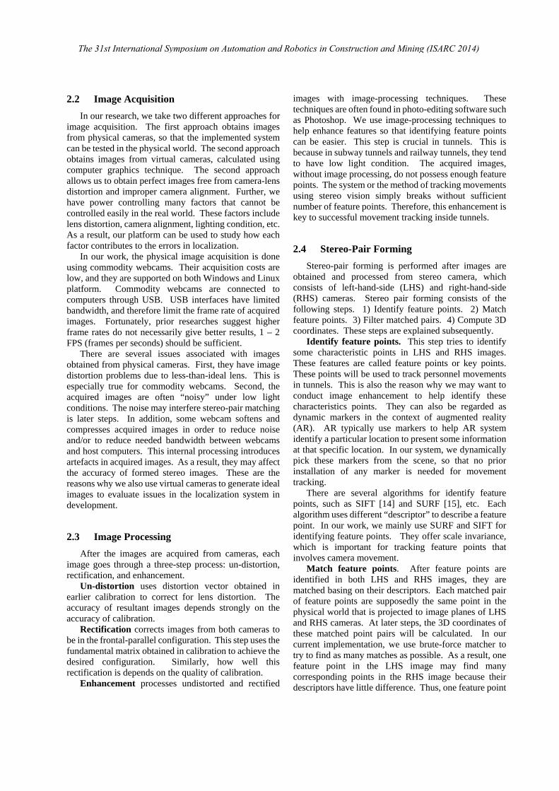
Figure 5 shows the computer generated reference chessboard for calibrating virtual cameras. Doing so allows us to inspect the quality of calibration of all camera parameters, including intrinsic matrices, distortion vectors, essential matrix, and fundamental matrix. The platform also enables us to determine the most convenient yet effective poses of the chessboard to calibrate these parameters.
Figure 6 shows the rectified images obtained from cameras (either virtual or physical ones). Showing this image can confirm that the calibrated essential matrix is correct, and after rectification the images from LHS and RHS cameras are indeed in front-parallel configuration with row alignment. If the images are acquired from virtual cameras, we can further inspect the intrinsic matrix and check their values to see if they match the settings of virtual cameras.
Figure 7 shows feature points identified and matched before filtering by a chosen algorithm in the system. Each line in the figure connects matching feature point in LHS and RHS images. The original LHS and RHS images are shown in Figure 4. These matches are obtained after rectification, thus all lines should be horizontal if matches are correct. It is obvious that
The 31st International Symposium on Automation and Robotics in Construction and Mining (ISARC 2014)
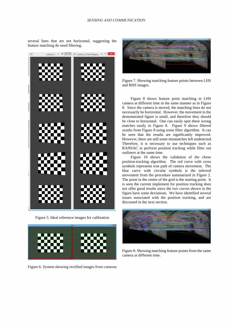
several lines that are not horizontal, suggesting the feature matching do need filtering.
Figure 5. Ideal reference images for calibration
Figure 6. System showing rectified images from cameras
Figure 7. Showing matching feature points between LHS and RHS images.
Figure 8 shows feature point matching in LHS camera at different time in the same manner as in Figure 8. Since the camera is moved, the matching lines do not necessarily be horizontal. However, the movement in the demonstrated figure is small, and therefore they should be close to horizontal. One can easily spot these wrong matches easily in Figure 8. Figure 9 shows filtered results from Figure 8 using some filter algorithm. It can be seen that the results are significantly improved. However, there are still some mismatches left undetected. Therefore, it is necessary to use techniques such as RANSAC to perform position tracking while filter out outliners at the same time.
Figure 10 shows the validation of the chose position-tracking algorithm. The red curve with cross symbols represents true path of camera movement. The blue curve with circular symbols is the inferred movement from the procedure summarized in Figure 2. The point in the centre of the grid is the starting point. It is seen the current implement for position tracking does not offer good results since the two curves shown in the figure have some deviations. We have identified several issues associated with the position tracking, and are discussed in the next section.
Figure 8. Showing matching feature points from the same camera at different time.
SENSING AND COMMUNICATION
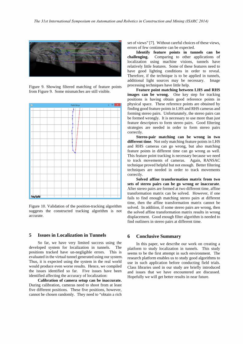
Figure 9. Showing filtered matching of feature points from Figure 9. Some mismatches are still visible.
Figure 10. Validation of the position-tracking algorithm suggests the constructed tracking algorithm is not accurate.
5 Issues in Localization in Tunnels
So far, we have very limited success using the developed system for localization in tunnels. The positions tracked have un-negligible errors. This is evaluated in the virtual tunnel generated using our system. Thus, it is expected using the system in the real world would produce even worse results. Hence, we compiled the issues identified so far. Five issues have been identified affecting the accuracy of localization:
Calibration of camera setup can be inaccurate. During calibration, cameras need to shoot from at least five different positions. These five positions, however, cannot be chosen randomly. They need to “obtain a rich
set of views” [7]. Without careful choices of these views, errors of few centimetre can be expected.
Identify feature points in tunnels can be challenging. Comparing to other applications of localization using machine visions, tunnels have relatively little features. Some of these features need to have good lighting conditions in order to reveal. Therefore, if the technique is to be applied in tunnels, additional light sources may be necessary. Image processing techniques have little help.
Feature point matching between LHS and RHS images can be wrong. One key step for tracking positions is having obtain good reference points in physical space. These reference points are obtained by finding good feature points in LHS and RHS cameras and forming stereo pairs. Unfortunately, the stereo pairs can be formed wrongly. It is necessary to use more than just feature descriptors to form stereo pairs. Good filtering strategies are needed in order to form stereo pairs correctly.
Stereo-pair matching can be wrong in two different time. Not only matching feature points in LHS and RHS cameras can go wrong, but also matching feature points in different time can go wrong as well. This feature point tracking is necessary because we need to track movements of cameras. Again, RANSAC technique proved helpful but not enough. Better filtering techniques are needed in order to track movements correctly.
Solved affine transformation matrix from two sets of stereo pairs can be go wrong or inaccurate. After stereo pairs are formed at two different time, affine transformation matrix can be solved. However, if one fails to find enough matching stereo pairs at different time, then the affine transformation matrix cannot be solved. In addition, if some stereo pairs are wrong, then the solved affine transformation matrix results in wrong displacement. Good enough filter algorithm is needed to find outliners in stereo pairs at different time.
6 Conclusive Summary
In this paper, we describe our work on creating a platform to study localization in tunnels. This study seems to be the first attempt in such environment. The research platform enables us to study good algorithms to use in such application before conducting field trials. Class libraries used in our study are briefly introduced and issues that we have encountered are discussed. Hopefully we will get better results in near future.
The 31st International Symposium on Automation and Robotics in Construction and Mining (ISARC 2014)

Acknowledgement
This work is funded by National Science Council of Taiwan under grant number 101-2221-E-011 -111 -MY2. Authors would like to thank Prof. T. D. Wang of National Taipei University of Science and Technology for providing tunnel-lining images for our study.
References
[1] National Transportation Safety Board (2007), “Ceiling Collapse in the Interstate 90 Connector Tunnel, Boston, Massachusetts, July 10, 2006,” Accident Report, NTSB/HAR-07/02, PB2007-916203, USA.
[2] Ministry of Land, Infrastructure, Transport and Tourism (MLIT) of Japan, “Sasago Tunnel Ceiling Collapseon the Chuo Expressway (Sequence of Events and Countermeasures),” On-line: http://www.mlit.go.jp/road/road_e/03key_challenges/1-2-1.pdf, accessed: 14/02/2014.
[3] Dayekh, S., Affes, S., Kandil, N., and Nerguizian, C., “Cooperative Localization in Mines Using Fingerprinting and Neural Networks,” Proceedings of Wireless Communications and Networking Conference (WCNC of IEEE), pp: 1 – 6, Sydney, NSW, 2010.
[4] Maimone, M., Cheng, Y., and Matthies, L. “Two years of Visual Odometry on the Mars Exploration Rovers”. Journal of Field Robotics, 24 (3): 169–186, 2007.
[5] Agrawal, M. “Real-time Localization in Outdoor Environments using Stereo Vision and Inexpensive GPS,” Proceed of the 18th International Conference on Pattern Recognition, Hong Kong, 2006.
[6] Hilsenbeck, S., Moller, A. , Huitl, R. , Schroth, G. , Kranz, M., and Steinbach, E. “Scale-preserving long-term visual odometry for indoor navigation,” Proceedings of International Conference on Indoor Positioning and Indoor Navigation (IPIN), pp. 1 – 10, Sydney, NSW, 2012.
[7] OpenCV, “Open Source Computer Vision”, On-line: http://opencv.org, Accessed: 14/02/2014.
[8] Bradski, G.R. and Kaehler, A. “Learning OpenCV – computer vision with the OpenCV library,” O’Reilly Media Inc., 1005 Gravenstein Highway North, Sebastopol, CA, USA, ISBN 978-0-596-51613-0.
[9] Heikkila, J. and Silven, O. “A four-step camera calibration procedure with implicit image correction,” Proceeding of the 1997 Conference on Computer Vision and Pattern Recognition: 1106, 1997.
[10] Fryer, J.G. and Brown, D.C. “Lens distortion for close-range photogrammetry,” Photogrammetric Engineering and Remote Sensing, 52:51-58, 1986.
[11] Brown, D.C. “Close-range camera calibration,” Photogrammetric Engineering, 37:855-866.
[12] Brown, D.C. “Decentering distortion of lenses”, Photogrammetric Engineering, 32:444-462, 1966.
[13] Bouguet, J.Y. “Matlab Calibration Tool,” On-line: http://www.vision.caltech.edu/bouguetj/calib_doc/, Accessed 14/02/2014.
[14] Lowe, D.G. “Distinctive image features from scale-invariant keypoints,” International Journal of Computer Vision 60: 91–110, 2004.
[15] Bay, H., Tuytelaars, T. and Gool, L. V. “SURF: Speeded up robust features,” Proceedings of the Ninth European Conference on Computer Vision, pp. 404–417, 2006.
[16] Kitware, “Visualization ToolKit,” On-line: http://www.vtk.org, Accessed: 14/02/2014.
[17] OpenMP ARB, “The OpenMP API specification for parallel programming,” On-line: http://openmp.org/mp/, Accessed 14/02/2014.
SENSING AND COMMUNICATION