Embed Size (px)
Citation preview
Third International Symposium on Distribution Automation and Demand Side Management
Pjdm Springs!; California January 1^ 93
PROJECT AND TECHNICAL SPECIFICATIONS OF THE TELECONTROL SYSTEM FOR THE MAR DEL PLATA ELECTRICAL DISTRIBUTION SYSTEM.
Erapresa Social de Energia de Buenos Aires (ESEBA S.A)
Rodolfo PELLIZZONIE m presa Social de Energía de Buenos Aires (ESEBA S.A.)
D epar tam en to Investigación y Desarrollo.55 Nro. 570 - C P 1900, La Pla ta , Argentina .
Jorge L. AGÜERO Pedro E. ISSOURIBEHERE
Juan C. BARBEROIn s t i tu to de Investigaciones Tecnológicas p a ra Redes y
Equipos Eléctricos ( I IT R E E ). Universidad Nacional de La P la ta . 48 y 116 - CP 1900, La Pla ta , A rgen tina
ABSTRACTThis paper describes a project of the Telecontrol System (STCl for the M a r del P l a ta Electrical Distribution System (SE M D P), which will provide the au to m a te d d is t r ibu t ion ne tw ork m anagement from a Control Center, for both, rural and urban areas. This projec t will also allow, in the medium term, to incorporate small and medium neighbouring urban centers to this STC.
This project was developed taking into account the IEC Standards and R ecom m enda tions relating to those topics involved (mainly the IEC-870 series, and represents by itself a new approach to the project and specif ication of this type of systems.
The technical specif ication emphasizes the complete set of S T C ’s operat iona l p a ram ete rs , defined and classified by the in te rna t iona l s tandards m entioned above.
The projected system includes the conventional SCADA basic and extended functions , and it will allow to add au tom ation functions in the m edium voltage level in the future.
1. INTRODUCTION.
The Argentine Republic, with a continental extension of about 2,780,400 sq.km and about 32.6 millions of inhabitants, is divided into 23 provinces. Among the most important ones, because of its extension, population and industrial development, is the Province of Buenos Aires. With an extension of about 307,571 sq.km and about 12.6 millions of inhabitants, this province is located in the central part of the country (Figure 1) .
The electrical service in the province is supplied by the Empresa Social de Energia de Buenos Aires (ESEBA S.A.), except for some cities such as La Plata and its surrounding urban areas, and those ones that surround the Buenos Aires City (Gran Buenos Aires). ESEBA regionals are shown in Figure 2. Some figures of the company, corresponding to 1990/91, are shown in Table 1.
- 1 -
Mar del Plata city is located in the middle-east of the Province of Buenos Aires, on the Atlantic's coast, and about 400 km away from Buenos Aires City, Federal Capital of Argentina. Mar del Plata is the main touristic resort of the country, with an important commercial activity during vacation periods. It has the principal fishing port of the country around which it was developed the proper industry. Stable population is about 500,000 people, and there is a capacity for about 1,000,000 people.
The Mar del Plata Electrical Service (MDP ES) supplies the energetic requirements of the city, and those of Batán, Chapadmalal and Santa Clara del Mar (small touristic urban areas).
The maximum demanded power (approximately 150 MW) is supplied by its own generating central whose installed power is 155 MW. Moreover, there is a connection with the ESEBA's Transmisión System (ETS) in 132 kV, from which it receives, or to which it supplies energy depending on the disponibility of the generating system. The MDP ES is caracterized by the figures summarized in Table 2, corresponding to 1990/91.
The Telecontrol System (TCS) projected for the MDP ES will allow the urban and rural distribution network to be managed from a Control Center (CC) . The process to be telecontrolled includes two levels: sub-transmission level in HV (Level 1, 132 kV) anddistribution level in MV (Level 2, 33 kV and 13.2 kV).
The TCS structure is based upon Primary and Secondary Distribution Operating Centers (DOC I and DOC II) , as indicated in Figure 3.The planned Telecontrolled Remote Stations (TRS) are:
- 4 Transformer Stations (TS) HV/MV (133/13.2 kV) , an another TS being projected at the present time that will be incorpored in the system.
- 3 Substations (SS) MV/MV (33/13.2 kV) , and another being build currently.
- 9 Distribution Centers (DC) in 13.2 kV.
This project will allow small and medium neighbouring urban centers to be included in the TCS for the medium term.
2. TCS FUNCTIONS.
Electrical-system operation with the TCS will manage both levels 1 and 2 (132 kV, 33 y 13.2 kV). These facilities will be achieved by implementing basic and extended SCADA functions, according with IEC 870 series of standards and recommendations.
- 2 -
2.1. Basic Functions.The planned point types and quantities for the TCS are shown in Table 3.
- Monitoring functions. Comprises telemetering, teleindication and telealarms. The last one includes alarms and protection actuation (trippings). Alarm grouping in RTU's (alarm information preprocessing) is planned, to reduce information traffic between RTU's and CC in case of alarm avalanches.
- Command functions. Commands will be either single or double, and they will correspond to:
• Switching-devices telecommands (circuit breakers and disconnectors).
• Unlocking telecommands for circuit breakers and disconnectors.
• General interlocking-annulation among TRS.
• Tap-changing telecommand.
• Alarm acknowledgement and cancelation in local alarm panels.
• Shedding load (associated with frequency relay tripping).
- Synchronization functions. Synchronization timming from the CC to all RTU's located in TRS's, with an error less than time-resolution specified for the TCS (.1 second).
- Time tagging functions. Information transmmited from RTU's to CC, will be sent with event occurrence time together with the data.
2.2. Extended Functions.Extended functions with mandatory implementation are:
- Man-Machine Interface.- Data Base Manager.- Switching-devices interlocking.
3. OPERATIONAL PARAMETERSOperational parameters were taken into account and specified according to International Standard IEC-870-4 [Ref.l], and other relevant standards and drafts of the IEC-870 series.
- 3 -
3.1. Availability
Availability is expressed either in percentual values (A) referred to 8760 hs, or in terms of unavailability time (Tu) expressed in hours/year. Predictable availability for both, the total TCS and its main parts, such as central-station equipment, TRS equipment, etc., and computer peripheric devices, will be computed according to IEC-870-4 [Ref.l]:
Ap = 100 • MTBF / (MTBF + MTTR)
The following parameters must be guarantied for equipment, subsystems and systems:
• reliability, expressed by the value MTBF in hours,• maintainability, expressed by the value MTTR in hours.
TCS's reliability will be verified according to IEC-870-4 [Ref.l], by means of the expression:
A = 100 • Ti / ( Ti + To)
being Ti the time in service, and To the time out of service of the part under consideration.
Required values for availability (unavailability) are:
• Control Center. A=99,93 % (Tu=6 hs/year).• Level 1. A=99,93 % (Tu=6 hs/year) .• Level 2. A= 99,86 % (Tu=12 hs/year).
3.2. Data IntegrityData integrity is expressed in terms of the probability of residual information error (IE), which includes the probability of undetected information losses, and the probability of undetected mistaken information, according to definitions from IEC-870-4 [Ref.l].A data integrity estimation was obtained by taking a bit error rate (BER) value lesser than 10~4 .
Data integrity will be verified indirectly by calculation, with formulas used to estimate reported values. Calculations will be made with measured BER values, and it will take into account the transmission protocol structure. BER measure will be made under normal-in-service operational and environmental conditions.
Required values for data integrity are:• Level 1 Telecommands. IE = 10~14.
” 10• Level 1 information except telecommands: IE = 10• Level 2 Telecommands. IE = 10-12.• Level 2 information except telecommands: IE = 10
- 4 -
These data integrity values must be obtained with the measured BER, which will not have to be greater than the value adopted to estimate data integrity values reported.
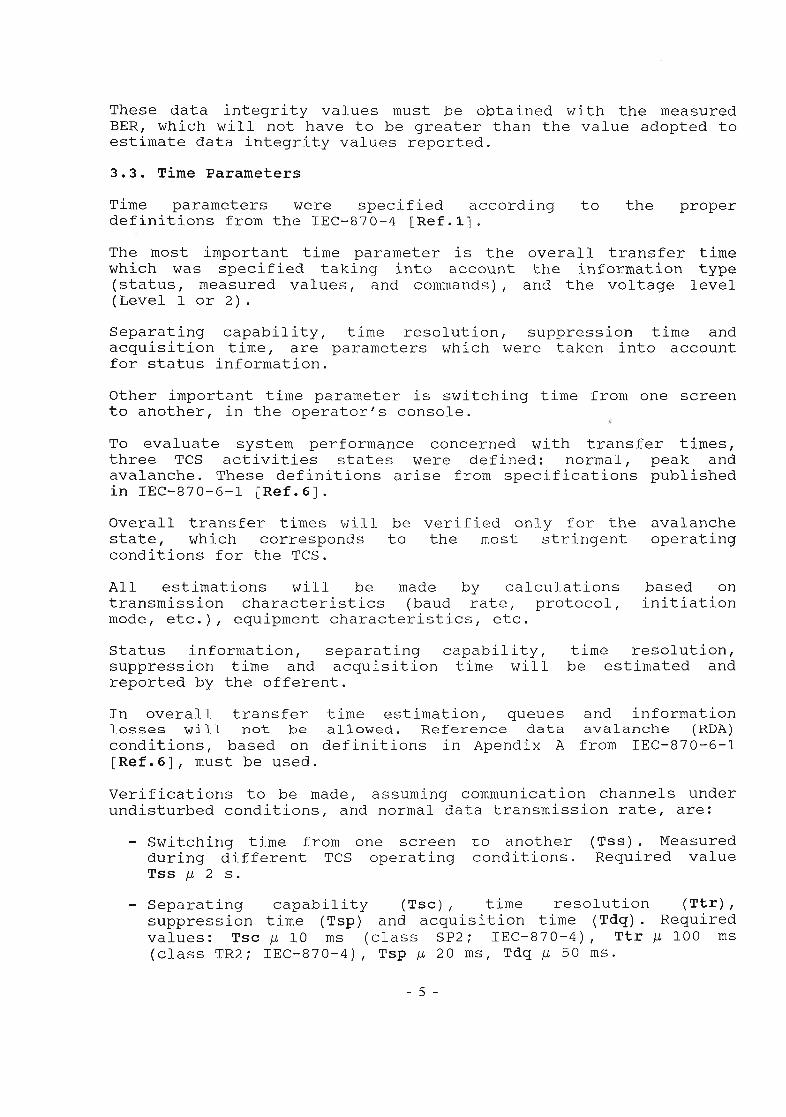
3.3. Time ParametersTime parameters were specified according to the proper definitions from the IEC-870-4 [Ref.l],The most important time parameter is the overall transfer time which was specified taking into account the information type (status, measured values, and commands), and the voltage level (Level 1 or 2 ) .
Separating capability, time resolution, suppression time and acquisition time, are parameters which were taken into account for status information.
Other important time parameter is switching time from one screen to another, in the operator's console.
To evaluate system performance concerned with transfer times, three TCS activities states were defined: normal, peak andavalanche. These definitions arise from specifications published in IEC-870-6-1 [Ref.6].
Overall transfer times will be verified only for the avalanche state, which corresponds to the most stringent operating conditions for the TCS.
All estimations will be made by calculations based on transmission characteristics (baud rate, protocol, initiation mode, etc.), equipment characteristics, etc.
Status information, separating capability, time resolution, suppression time and acquisition time will be estimated and reported by the offerent.
In overall transfer time estimation, queues and information losses will not be allowed. Reference data avalanche (RDA) conditions, based on definitions in Apendix A from IEC-870-6-1 [Ref.6], must be used.
Verifications to be made, assuming communication channels under undisturbed conditions, and normal data transmission rate, are:
- Switching time from one screen to another (Tss). Measured during different TCS operating conditions. Required value Tss id 2 s.
- Separating capability (Tsc), time resolution (Ttr),suppression time (Tsp) and acquisition time (Tdq). Required values: Tsc id 10 ms (class SP2 ; IEC-870-4), Ttr /i 100 ms(class TR2 ; IEC-870-4), Tsp id 20 ms, Tdq ¡d 50 ms.
- 5 -
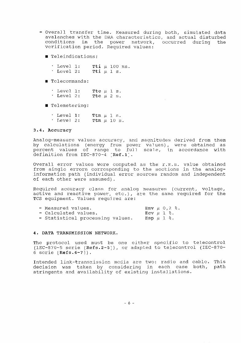
- Overall transfer time. Measured during both, simulated data avalanches with the DRA characteristics, and actual disturbed conditions in the power network, occurred during the verification period. Required values:
3.4. AccuracyAnalog-measure values accuracy, and magnitudes derived from them by calculations (energy from power values), were obtained as percent values of range to full scale, in accordance with definition from IEC-870-4 [Ref.l].
Overall error values were computed as the r.m.s. value obtained from single errors corresponding to the sections in the analog- information path (individual error sources random and independent of each other were assumed).
Required accuracy class for analog measures (current, voltage, active and reactive power, etc.), are the same required for the TCS equipment. Values required are:
- Measured values. Emv p 0,2 %.- Calculated values. Ecv /i 1 %.- Statistical processing values. Esp /i 1 %.
4. DATA TRANSMISSION NETWORK.
The protocol used must be one either specific to telecontrol (IEC-870-5 serie [Refs.2-5]), or adapted to telecontrol (IEC-870- 6 serie [Refs.6-7]).Intended link-transmission media are two: radio and cable. This decision was taken by considering in each case both, path stringents and availability of existing installations.
- 6 -
■ Teleindications:
• Level 1: Tti 100 ms.• Level 2: Tti 1 s .
■ Telecommands:
• Level 1: Ttc M 1 s .• Level 2: Ttc M 2 s .
■ Telemetering:
• Level 1: Ttm M 1 s .• Level 2: Ttm 10 s .
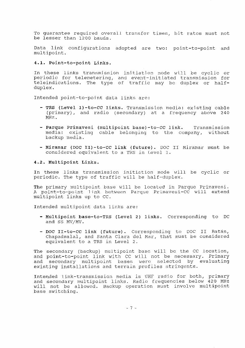
To guarantee required overall transfer times, bit rates must not be lesser than 1200 bauds.
Data link configurations adopted are two: point-to-point andmultipoint.
4.1. Point-to-point Links.In these links transmission initiation mode will be cyclic or periodic for telemetering, and event-initiated transmission for teleindications. The type of traffic may be duplex or halfduplex .
Intended point-to-point data links are:
- TRS (Level 1)—to—CC links. Transmission media: existing cable (primary), and radio (secondary) at a frequency above 240 MHz.
- Parque Primavesi (multipoint base)-to-CC link. Transmissionmedia: existing cable belonging to the company, withoutbackup media.
- Miramar (DOC II)-to-CC link (future). DOC II Miramar must be considered equivalent to a TRS in Level 1.
4.2. Multipoint Links.In these links transmission initiation mode will be cyclic or periodic. The type of traffic will be half-duplex.
The primary multipoint base will be located in Parque Primavesi. A point-to-point link between Parque Primavesi-CC will extend multipoint links up to CC.
Intended multipoint data links are:
- Multipoint base-to-TRS (Level 2) links. Corresponding to DC and SS MV/MV.
- DOC II-to-CC link (future). Corresponding to DOC II Batán, Chapadmalal, and Santa Clara del Mar, that must be considered equivalent to a TRS in Level 2.
The secondary (backup) multipoint base will be the CC location, and point-to-point link with CC will not be necessary. Primary and secondary multipoint bases were selected by evaluating existing installations and terrain profiles stringents.
Intended link-transmission media is UHF radio for both, primary and secondary multipoint links. Radio frequencies below 420 MHz will not be allowed. Backup operation must involve multipoint base switching.
- 7 -
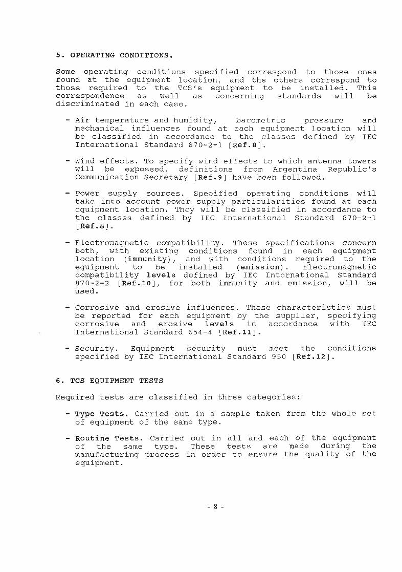
5. OPERATING CONDITIONS.
Some operating conditions specified correspond to those ones found at the equipment location, and the others correspond to those required to the TCS's equipment to be installed. This correspondence as well as concerning standards will be discriminated in each case.
- Air temperature and humidity, barometric pressure and mechanical influences found at each equipment location will be classified in accordance to the classes defined by IEC International Standard 870-2-1 [Ref.8].
- Wind effects. To specify wind effects to which antenna towers will be expossed, definitions from Argentina Republic's Communication Secretary [Ref.9] have been followed.
- Power supply sources. Specified operating conditions willtake into account power supply particularities found at each equipment location. They will be classified in accordance to the classes defined by IEC International Standard 870-2-1 [Ref.8].
- Electromagnetic compatibility. These specifications concernboth, with existing conditions found in each equipmentlocation (immunity), and with conditions required to the equipment to be installed (emission). Electromagnetic compatibility levels defined by IEC International Standard 870-2-2 [Ref.10], for both immunity and emission, will be used.
- Corrosive and erosive influences. These characteristics mustbe reported for each equipment by the supplier, specifying corrosive and erosive levels in accordance with IECInternational Standard 654-4 [Ref.11].
- Security. Equipment security must meet the conditionsspecified by IEC International Standard 950 [Ref.12].
6. TCS EQUIPMENT TESTSRequired tests are classified in three categories:
- Type Tests. Carried out in a sample taken from the whole set of equipment of the same type.
- Routine Tests. Carried out in all and each of the equipment of the same type. These tests are made during the manufacturing process in order to ensure the quality of the equipment.
- 8 -
- Acceptance Tests. Carried out under prescribed conditions in N samples of an equipment type. N is obtained as the integer greater than 2 times the cubic root of the total number of equipments of that type. The N samples will be randomly taken from the total number of equipment supplied. These tests, depending on its nature will be carried out at either manufacturing or installation location.
Both equipment-location operating conditions and required reliability degree make tests to be a fundamental item to take into account. Within this item, electromagnetic-compatibility tests are the ones that impose the most stringent requirements.
6.1.1. Electromagnetic-Compatibility TestsAccording to IEC Draft 870-2-2 [Ref.10], two types ofelectromagnetic-compatibility tests are defined: immunity testsand emission tests.
- Electromagnetic-immunity tests:
• Harmonics.• Interharmonics.• Signalling systems.• Voltage fluctuations.• 100/1300 jus surges.• 1.2/50 /is and 8/20 /is.• Fast transient burst.• Ring waves.• Damped oscillatory waves.• 10/700 /is surges.• Electrostatic discharge.• Power frequency magnetic field.• Pulse magnetic field.• Damped oscillatory magnetic field.• Electromagnetic (Radio) field.
- Electromagnetic-emission tests:
• Harmonic currents.• Voltage fluctuations.• LF disturbance voltages.• Transient disturbance voltages.• RF disturbance voltages.• RF disturbance currents.• RF radiated fields.
Equipment located at CC and at TRS will be considered distinctly, and in each case, four types of equipment and (or) installations will be classified:
- AC power supply.- DC power supply.
- 9 -
- Control and signal.- Telecommunication lines.
Furthermore, for each type of equipment it is specified required immunity level, allowed emission level, required tests and their category (type, routine or acceptance).
Table 4 shows the form used to specify some required immunity tests. Performed routine tests must be reported by themanufacturer.
6.1.2. Other testsFollowing equipment or system parts will be subjected to tests, under conditions specified in the publications hereby mentioned:
- batteries (IEC-623, items 4.2 to 4.5);
- battery chargers (IEC-146, items 492.1 to 492.11);
- Uninterruptible power supplies (IEC-146-4, items 7.4.1 to 7.4.30; IEC-146-5, items 6.3.1 to 6.3.10);
- transmitters (IEC-244-1, clauses 11, 12, 17 and 21; 244-2,clauses 7, 8 and 11; 244-3, clauses 9 and 12; 244-3B,clauses 24 and 26; 244-6, clauses 18 and 19);
- receivers (IEC-315-1, clause 23; 315-8, clauses 5, 13, 16and 25) ;
- antennas (EIA, RS-329);- racks (IEC-144, IRAM 121).
7. CONCLUSION
The goal of this paper was to summarize the specifications of the projected telecontrol system for Mar del Plata Electrical Service, in accordance with international standarizations on this matter.Functional requirements as well as inherent properties of the system were emphasized. Availability, maintainability, time parameters, etc. affect in many ways the global-performance system, and they actual importance is noted only under exceptional circumstances, or when the system must be extended.
Furthermore, those aspects for similar systems may contribute to adopt both, project criteria or method, and equipment or system parts specification or verification were emphasized.
- 10 -
In this context, operational parameter specifications and electromagnetic compatibility test were required for the component parts of the system, all based on international standards and recommendations, they constitute the most outstanding contribution.
8. REFERENCES.[1] International Electrotechnical Commission. Telecontrol equi
pment and systems. Part 4: Performance requirements. IEC International Standard 870-4, Fst.Ed., March, 1990.
[2] International Electrotechnical Commission. Telecontrol equipment and systems. Part 5: Transmission Protocols. SectionOne: Transmission frame formats. IEC International Standard 870-5-1, Fst.Ed., February, 1990.
[3] International Electrotechnical Commission. Telecontrol equipment and systems. Part 5: Transmission Protocols. SectionTwo: Link transmission procedures. IEC International57(Central Office)57, IEC Draft 870-5-2, Rev.11, December, 1989 .
[4] International Electrotechnical Commission. Telecontrol equipment and systems. Part 5: Transmission Protocols. SectionThree: Structure of application data. IEC International57(Secretariat)104, IEC Draft 870-5-3, August, 1990.
[5] International Electrotechnical Commission. Telecontrol equipment and systems. Part 5: Transmission Protocols. SectionFour: Codding specification of application data. IEC International 57(Secretariat)105, IEC Draft 870-5-4, August, 1990.
[6] International Electrotechnical Commission. Telecontrol equipment and systems. Part 6: Telecontrol protocols compatiblewith ISO and CCITT standards. Section One: Application context and organization of standards. IEC 57(Secretariat)106, IEC Draft 870-6-1, August, 1990.
[7] International Electrotechnical Commission. Telecontrol equipment and systems. Part 6: Telecontrol protocols compatiblewith ISO and CCITT standards. Section Two: Use of base standards (OSI Layers 1-4). IEC 57(Secretariat)109, IEC Draft 870-6-2, May, 1991.
[8] international Electrotechnical commission. Telecontrol equipment and systems. Part 2: Operating conditions. SectionOne: Environmental conditions and power supplies. IEC International Standard 870-2-1, Fst.Ed., 1987.
11
[9] R.A. Communication Secretary. Resolución 874 SC/88. SC-AN2-39.11. Estructuras de acero para antenas. 1988.
[10] International Electrotechnical Commission. Telecontrol equipment and systems. Part 2 : Operating conditions. SectionTwo : Electromagnetic compatibility, corrosive and erosiveinfluences. IEC 57(Secretariat)98, IEC Draft 870-2-2,2nd.Ed., May, 1990.
[11] International Electrotechnical Commission. Telecontrol equipment and systems. Part 2 : Operating conditions. SectionOne : Environmental conditions and power supplies. IEC International Standard 870-2-1, Fst.Ed., 1987.
[12] International Electrotechnical Commission. Safety ofinformation technology equipment including electrical business equipment. IEC International Standard 950, Fst.Ed., 1986, and Ammendment Num.2, 1990
- 12 -