Embed Size (px)
Citation preview


Thank you for purchasing a Honda generator.
This manual covers operation and maintenance of the EX800 generator. All information in this publication is based on the latest product information available at the time of approval for printing. Honda Motor Co., Ltd. reserves the right to make changes at any time without notice and without incurring any obligation.
No part of this publication may be reproduced without written permission.
This manual should be considered a permanent part of the generator and remain with the generator when sold.
Pay special attention to statements preceded by the following words:
m Indicates a strong possibility of severe personal injury or loss of life if instructions are not followed.
CAUTION: Indicates a possibility of personal injury or equipment damage if instructions are not followed.
NOTE: Gives helpful information.
If a problem should arise, or if you have any questions about the generator, consult an authorized Honda dealer.
w The Honda generator is designed to give safe and dependable service if operated according to instructions. Read and understand the Owner’s Manual before operating the generator. Failure to do so could result in personal injury or equipment damage.
1
CONTENS
CONTENTS 1. GENERATOR SAFETY ................................... 3 2. COMPONENT IDiNTlFlCATlON ............................ 4 3. PRE-OPERATION CHECK ................................. 6 4. STARTING THE ENGINE ................................... 8 5. GENERATOR USE ....................................... 11 6. STOPPING THE ENGINE ................................... 14 7. MAINTENANCE ......................................... 15
.8. TRANSPORTING/STORAGE ............................... 23 9. TROUBLESHOOTING ..... ; .................... . ............ 24
lO.WIRING DIAGRAM ...................................... 26 11. SPECIFICATIONS ................. r ....................... 28 12. WARRANTY SERVICE .................................... 29
2

1. GENERATOR SAFETY
To ensure safe operation -
l Place the generator at least 1 m (3 ft) away from buildings or other equip- ment when operating the generator.
l Operate the generator on a level surface. If the generator is tilted, fuel spillage may result.
l Exhaust gas contains poisonous carbon monoxide. Never run the generator in an enclosed area. Be sure to provide adequate ventilation.
l Know how to stop the generator quickly and understand operation of all the controls. Never permit anyone to operate the generator without proper instructions.
l Keep children and pets away from the generator when it is in operation. l Keep away from rotating parts while the generator is running. l The generator is a potential source of electrical shocks when misued; do not
operate with wet hands. l Do not operate the generator in rain or snow and do not let it get wet. l Connections for standby power to a building’s electrical system must be
made by a qualified electrician and must comply with all applicable laws and electrical codes. Improper connections can allow electrical current from the generator to backfeed into the utility lines. Such backfeed may electrocute utility company workers or others who contact the lines dur,ing a power outage, and when utility power is restored, the generator may ex- plode, burn, or cause fires in the building’s electrical system.
When charging a battery -
l Battery electrolyte contains sulphuric acid. Protect your eyes, skin and clothing. In case of contact, flush thoroughly with water and call a doctor if your eyes were exposed.
l Batteries generate hydrogen gas which can be highly explosive. Do not smoke or allow flames or sparks near a battery, especially while charging it.
3
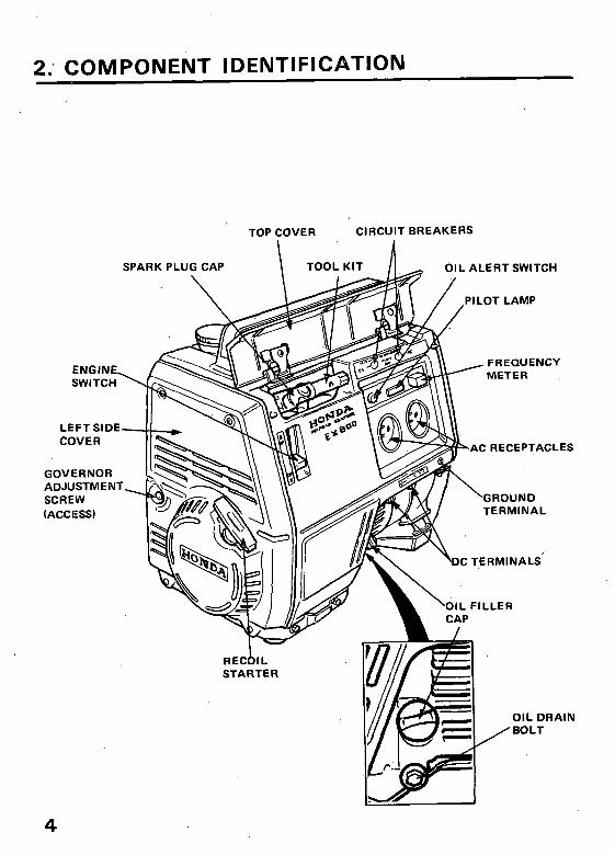
2., COMPONENT IDENTIFICAT.ION
TOP COVER CIRCUIT BREAKERS
L ALERT SWITCH
PILOT LAMP
FREQUENCY METER
C RECEPTACLES
GOVERNOR ADJUSTMENT
TERMINAL
\ dlL FILLER
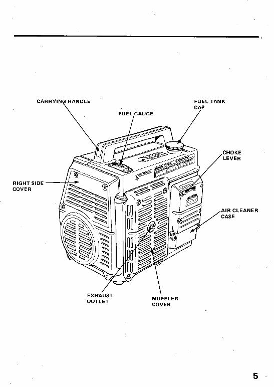
CA ,RRYING HANDLE
\.
FUEL GAUGE
I
RIGHT SI COVER
DE
EXHAUST OUTLET
FUEL TANK CAP
\ MUFFLER COVER
3. IPRE-QPERATBON CHECK
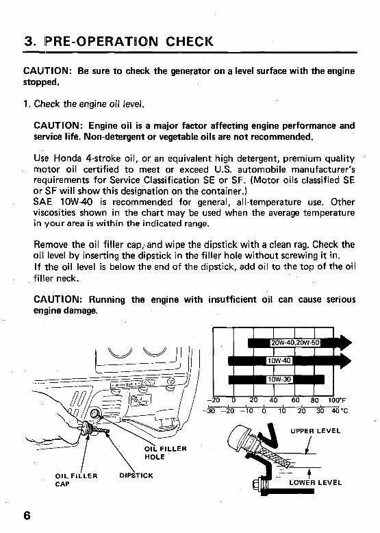
CAUTION: Be sure to check the generator on a level surface with the engine stopped.
1. Check the engine oil level.
CAUTION: Engine oil is a major factor affecting engine performance and service life. Non-detergent or vegetable oils are not recommended.
Usfe Honda 4-stroke oil, or an equivalent high detergent, premium quality motor oil certified to meet or exceed U.S. automobile manufacturer’s requirements for Service Classification SE or SF. (Motor oils classified SE or SF will show this designation on the container.) SAE low-40 is recommended for general, all-temperature use. Other viscosities shown in the chart may be used when the average temperature in your area is within the indicated range.
Remove the oil filler cap,,and wipe-the dipstick with a clean rag. Check the oil level by inserting the dipstick in the filler hole without screwing it in. If the oil level is below the end of the dipstick, add oil to the top of the oil filler neck.
CAUTION: Running the engine with insufficient oil can cause serious engine damage.
CAP
-20 0 20 40 60 80 100°F 1 1
-30 ,720 -10 0 10 20 30 40°C
6
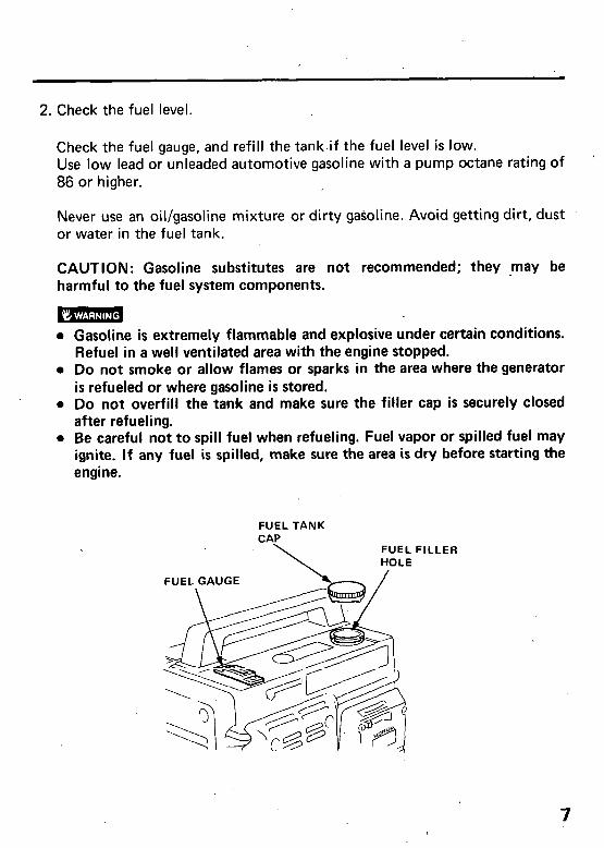
2. Check the fuel level.
Check the fuel gauge, and refill the tank.if the fuel level is low. Use low lead or unleaded automotive gasoline with a pump octane rating of 86 or higher.
Never use an oil/gasoline mixture or dirty gakoline. Avoid getting dirt, dust or water in the fuel tank.
CAUTION: Gasoline substitutes are not recommended; they -may be harmful to the fuel system components.
l Gasoline is extremely flammable and explosive under certain conditions. Refuel in a well ventilated area with the engine stopped.
l Do not smoke or allow flames or sparks in the area where the generator is refueled or where gasoline is stored.
l Do not overfill the tank and make sure the filler cap is securely closed after refueling.
l Be careful not to spill fuel when refueling. Fuel vapor or spilled fuel may ignite. If any fuel is spilled, make sure the area is dry before starting the engine.
FUEL TANK CAP
FUEL FILLER
7
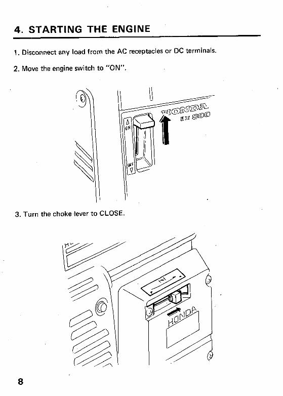
4. STARTING THE ENGINE
1. Disconnect any load from the AC receptacles or DC terminals.
2. Move the engine switch to “ON”.
3. Turn the choke.lever to CLOSE.
8
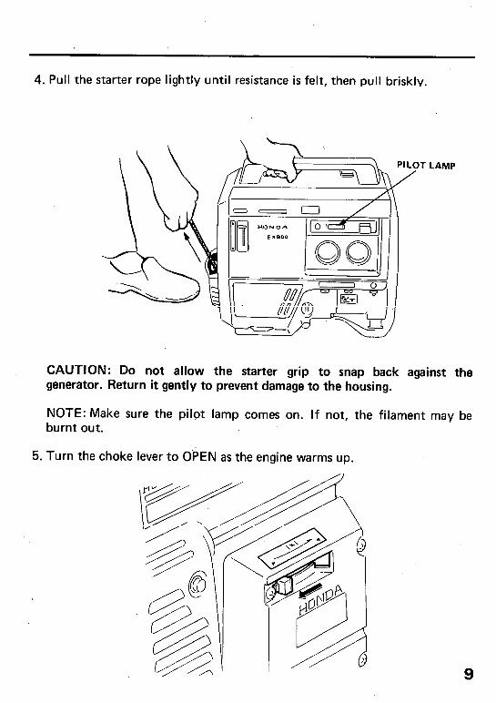
4. Pull the starter rope lightly until resistance is felt, then pull briskly,
LAMP
CAUTION: Do not allow the starter grip to snap back against the generator. Return it gently to prevent damage to the housing.
NOTE: Make sure the pilot lamp comes on. If not, the filament may be burnt out.
5. Turn the choke lever to OPEN as the engine warms up.
9
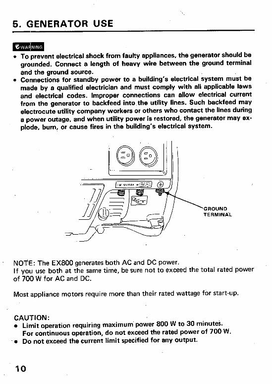
5. GENERATOR USE
l To prevent electrical shock from faulty appliances, the generator should be grounded. Connect a length of heavy wire between the ground terminal and the ground source.
l Connections for standby power to a building’s electrical system must be made by a qualified electrician and must comply with all applicable laws and electrical codes. Improper connections can allow electrical current from the generator to backfeed into.the utility lines. Such backfeed may electrocute utility company workers or others who contact the lines during a power outage, and when utility power is restored, the generator may ex- plode, burn, or cause fires in the building’s electrical system.
GROUND TERMINA’L
NOTE: The EX800 generates both AC and DC power. If you use both at the same time, be sure not to exceed the total rated power of 700 W for AC and DC.
Most appliance motors require more than their rated wattage for start-up.
CAUTION: 0 Limit operation requiring maximum’ power 800 W to 30 minutes.
For continuous operation, do not exceed the rated power’of 700 W. l Do not exceed the current limit specified for any output.
10
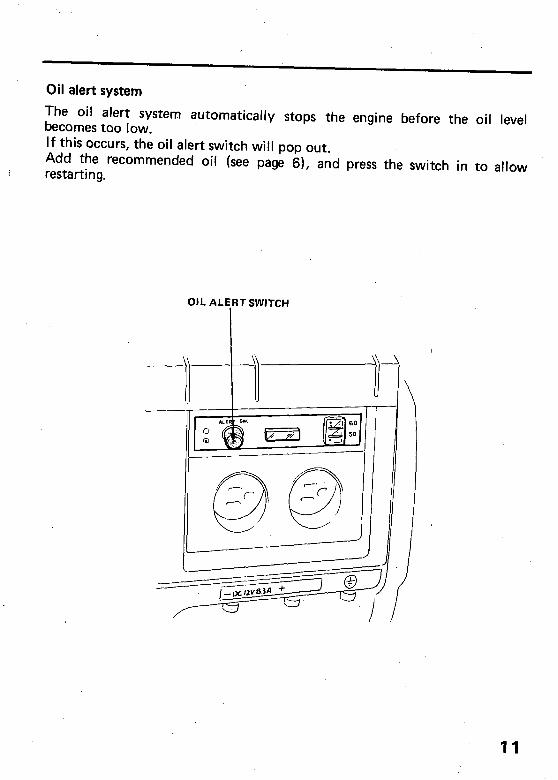
Oil alert system
The oil alert system automatically stops the engine before the oil level becomes too low. If this occurs, the oil alert switch will pop out. Add the recommended oil (see page 6), and press the switch in to allow restarting.
OIL ALERT SWITCH
11
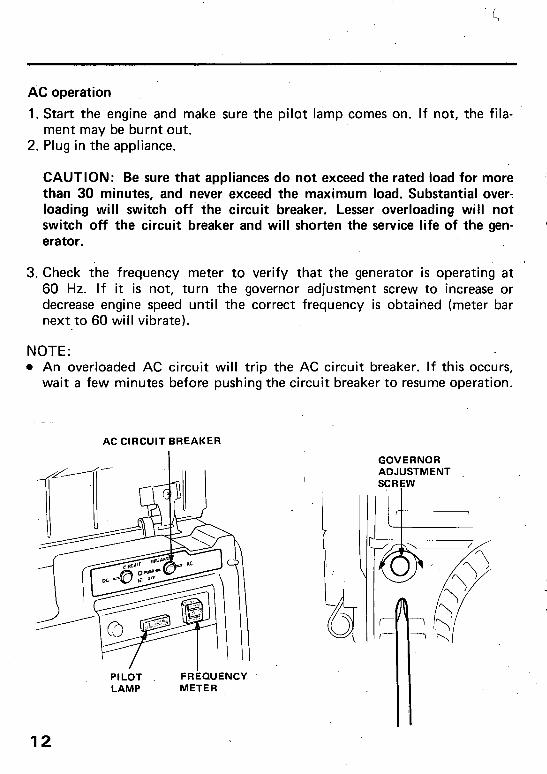
AC operation
1. Start the engine and make sure the pilot lamp comes on. If not, the fila- ment may be burnt out.
2. Plug in the appliance.
CAUTION: Be sure that appliances do not exceed the rated load for more than 30 minutes, and never exceed the maximum load. Substantial over-. loading will switch off the circuit breaker. Lesser overloading will not switch off the circuit breaker and will shorten the service life of the gen- erator.
3. Check the frequency meter to verify that the generator is operating at 60 Hz. If it is not, turn the governor adjustment screw to increase or decrease engine speed until the correct frequency is obtained (meter bar next to 60 will vibrate).
NOTE: l An overloaded AC circuit will trip the AC circuit breaker. If this occurs,
wait a few minutes before pushing the circuit breaker to resume operation.
AC CIRCUIT BREAKER
I “1
6 PILOT FRkXJENCY LAMP METER
GOVERNOR ADJUSTMENT SCRFW
12
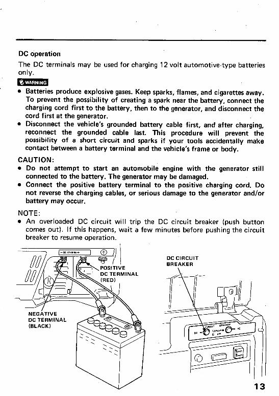
DC operation
The DC terminals may be used for charging 12 volt automotive-type batteries only.
- l Batteries produce explosive gases. Keep sparks, flames, and cigarettes away.
To prevent the possibility of creating a spark near the battery, connect the charging cord first to the battery, then to the generator, and disconnect the cord first at the generator.
l Disconnect the vehicle’s grounded battery cable first, and after charging, reconnect the grounded cable last. This procedure will prevent the possibility of a short circuit and sparks if your tools accidentally make contact between a battery terminal and the vehicle’s frame or body.
CAUTION: l Do not attempt to start an automobile engine with the generator still
connected to the battery. The generator may be damaged. l Connect the positive battery terminal to the positive charging cord. Do
not reverse the charging cables, or serious damage to the generator and/or battery may occur.
NOTE: l An overloaded DC circuit will trip the DC circuit breaker (push button
comes .out). If this happens, wait a few minutes before pushing the circuit breaker to resume operation.
DC TERMINAL
DC CIRCUIT BREAKER
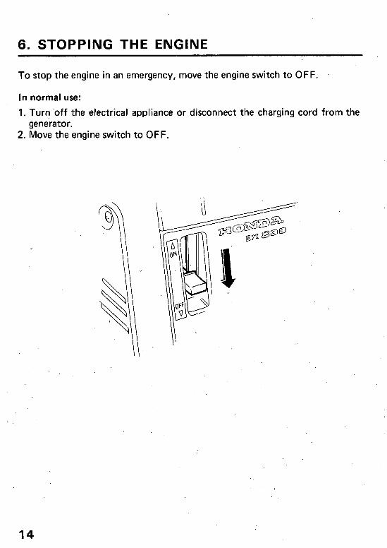
6. STOPPING THE ENGINE
To stop the engine in an emergency, move the engine switch to OFF.
In normal use:
1. Tur? ‘off the electrical appliance or disconnect the charging cord from the generator.
2. Move the engine switch to OFF.
14
7. MAINTENANCE
The purpose of the maintenance schedule and adjustment is to keep the generator in the best operating condition. Inspect or service as scheduled in the table on the next page.
m Shut off the engine before performing any maintenance. If the engine must be run, make sure the area is well ventilated. The exhaust con- tains poisonous carbon monoxide gas.
CAUTION: Use only genuine HONDA parts or their equivalent. The use of replacement parts which are not of equivalent quality may damage the generator.
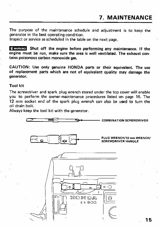
Tool kit
The screwdriver and spark plug wrench stored under the top cover will enable you to perform the owner-maintenance procedures listed on page 16. The 12 mm socket end of the spark plug wrench can also be used to turn the oil drain bolt. Always keep the tool kit with the.generator.
c COMBINATION SCREWDRIVER
PLUG WRENCH/l2 mm WRENCH/ SCREWDRIVER HANDLE
--
15
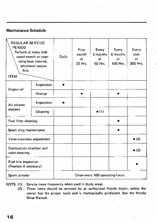
Maintenance Schedule
REGULAR SERVICE
Perform at every indi-
cated month or oper-
ating hour interval,
whichever occurs
First Every Every Every
Daily month 3 months 6 months year
or or or or
20 Hrs. 50 Hrs. 100 Hrs. 300 Hrs.
Engine oil
Inspection l
Change . l ’
Combustion chamber and
Fuel line inspection
(Replace if necessary)
Spark arrester Clean every 100 operating hours.
(2) : These items should be serviced by an authorized Honda-dealer, unless the
owner has. the proper tools and is mechanically proficient. See the Honda
Shop Manual.
NOTE (1) : Service more frequently when used in dusty areas.
16
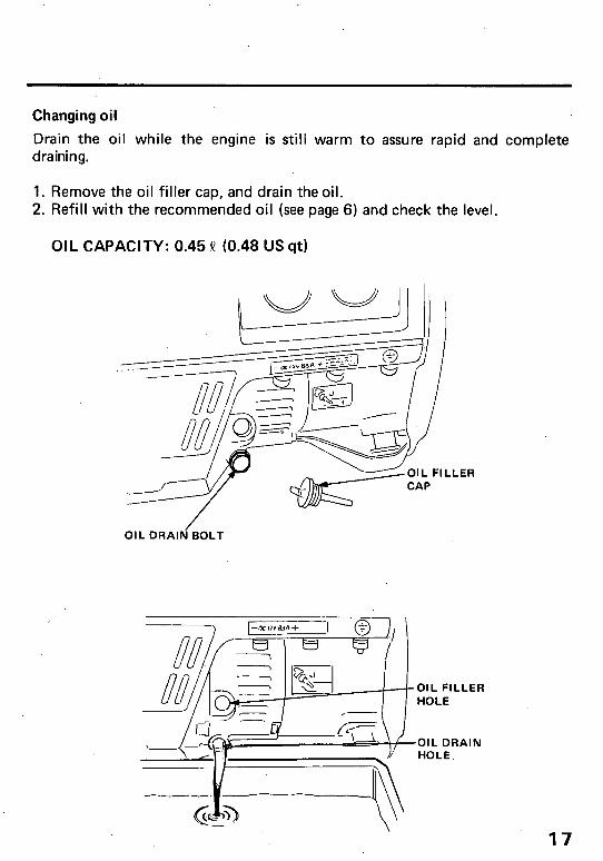
Changing oil
Drain the oil while the engine is still warm to assure rapid and complete draining.
1. Remove the oil filler cap, and drain the oil. 2. Refill with the recommended oil (see page 6) and check the level.
OIL CAPACITY: 0.45 Q (0.48 US qt)
OIL DRAIN BOLT
.LER
17
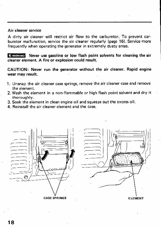
Air cleaner service
A dirty air cleaner will restrict air flow to the carburetor. To prevent car- buretor malfunction, service the air cleaner regularly (page 16). Service more frequently when operating the generator in extremely dusty areas.
B Never use gasoline or low flash point solvents for cleaning the air cleaner element. A fire or explosion could result.
CAUTION: Never run the generator without the air cleaner. Rapid engine wear.may result.
1. Unsnap the air cleaner case springs, remove the air cleaner case and remove the element.
2. Wash the element in a non-flammable or high flash point solvent and dry it thoroughly;
3. Soak the element in clean engine oil and squeeze out the excess oil. 4. Reinstall the air cleaner element and the case.
c \ , \
/ \ I \ I- /------’ z I -- f --\
CASE SPRINGS ’ I,
ELEMENT
18
Spark plug service
Recommended spark plug: BPR4HS-10 (NGK) or W14FPRULlO (ND)
/
To ensure proper engine operation, the spark plug must be properly gapped and free of deposits.
1. Remove the spark plug cap. 2. Use the wrench supplied in the tool kit to remove the spark plug.
3. Visually inspect the spark plug. Discard it if the insulator is cracked or chipped. Clean the spark plug with a wire brush if it is to be reused.
4. Measure the plug gap with a feeler gauge. The gap should be 0.9-l’.O mm (0.035-0.039 in). Correct as necessary by bending the side electrode.
0.9 mm-l.0 mm 10.035-0.039 in)
19
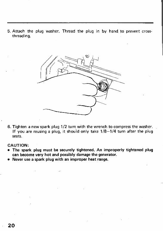
5. Attach the plug washer. Thread the plug in by hand 10 prevent cross- threading.
6. Tighten a new spark plug l/2 turq with the wrench to compress the washer. If you.are reusing a plug, it should only take l/8-1/4 turn after the plug seats.
CAUTION: l The spark plug must be securely tightened. An improperly tightened plug
can become very hot and possibly damage the generator. l Never use a spark plug with an improper heat range.
20
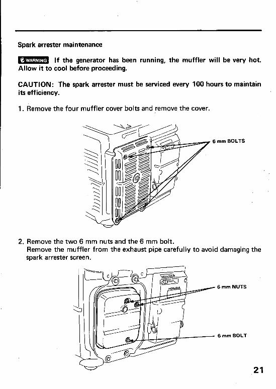
Spark arrester maintenance
M If the generator has been running, the muffler will be very hot. Allow it to cool before proceeding.
CAUTION: The spark arrester must be serviced every 100 hours to maintain its efficiency.
1. Remove the four muffler cover bolts and remove the cover.
6 mm BOLTS
2. Remove the two 6 mm nuts and the 6 mm bolt. Remove the muffler from the exhaust pioe carefully to avoid damaging the spark arrester screen.
6 mm NUTS
6 mm BOLT
21
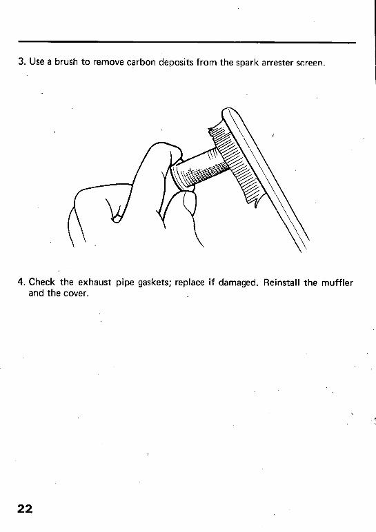
3. Use a brush to remove carbon deposits from the spark arrester screen.
4. Check the exhaust pipe gaskets; replace if damaged. Reinstall the muffler and the cover.
22
8. T.RANSPORTING/STORAGE
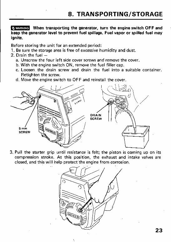
B When transporting the generator, turn the engine switch OFF and keep the generator level to prevent fuel spillage. Fuel vapor or spilled fuel may ignite.
Before storing the unit for an extended period: 1. Be sure the storage area is free of excessive humidity and dust. 2. Drain the fuel -
a. Unscrew the four left side cover screws and remove the cover. b. With the engine switch ON, remove the fuel filler cap. c. Loosen the drain screw and drain the fuel into a suitable container.
Retighten the screw. d. Move the engine switch to OFF and reinstall the cover.
I V 3. Pull the starter grip until resistance is felt; the piston is coming up on its
compression ,stroke. At this position, the exhaust and intake valves are closed, and this will help protect the engine from corrosion.
23
‘9. TROUBLESHOOTING
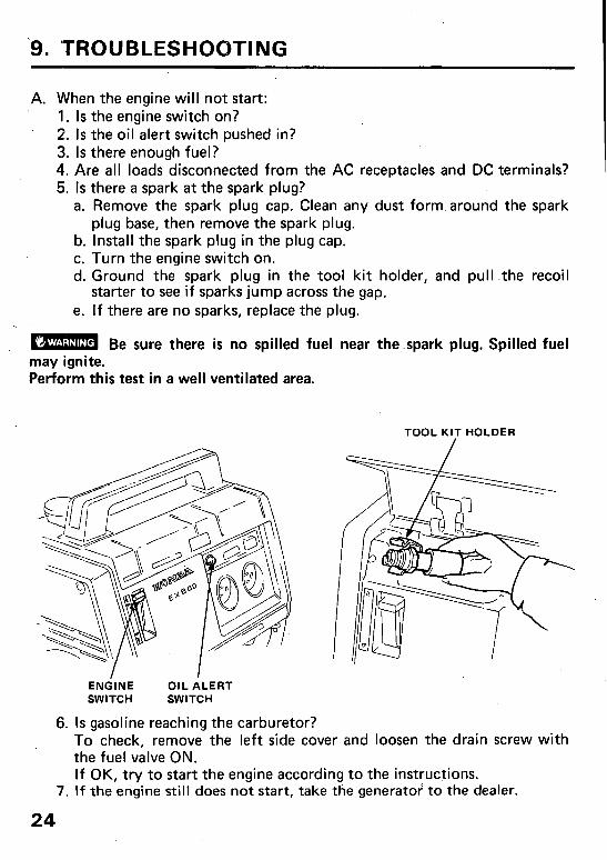
A. When the engine will not start: 1. Is the engine switch on? 2. Is the oil alert switch pushed in? 3. Is there enough fuel? 4. Are all loads disconnected from the AC receptacles and DC terminals? 5. Is there a spark at the spark plug?
a. Remove the spark plug cap. Clean any dust form around the spark plug base, then remove the spark plug.
b. Install the spark plug in the plug cap. c. Turn the engine switch on. d. Ground the spark plug in the tool kit holder, and pull .the recoil
starter to see if sparks jump across the gap. e. If there are no sparks, replace the plug.
m Be sure there is no spilled fuel near the.spark plug. Spilled fuel may ignite. Perform this test in a well ventilated area.
TOOL KIT HOLDER
ENGINE OIL ALERT SWITCH SWITCH
6. Is gasoline reaching the carburetor? To check, remove the left side cover and loosen the drain screw with the fuel valve ON. If OK, try to start the engine according to the instructions.
7. If the engine still does not start, take ttie generator’ to the dealer.
24
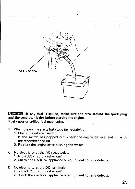
DRAIN S
B If any fuel is. spilled, make sure the area around the spaw plug and the generator is dry before starting the engine. Fuel vapor or spilled fuel may ignite.
B. When the engine starts but stops immediately; 1. Check the oil alert switch.
If the switch has popped out, check the engine oil level and fill,with the recommended oil.
2. Re-start the engine after’pushing the switch.
C. No electricity at the AC receptacles: i. Is the AC circuit breaker on? 2. Check the electrical appliance or equipment for any defects.
D. No electricity at the DC terminals: 1. Is the DC circuit breaker on? 2. Check the electrical appliance or equipment for any defects.
25
-. G
ENEl
iAro
n BL
OC
K
-ttt
1
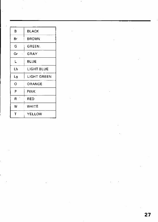
B BLACK
Br BROWN
G GREEN.
Gr GRAY
L BLUE
Lb LIGHT BLUE
Lg LIGHT GREEN
0 ORANGE
P PINK
R RED
W WHITE
T YELLOW
27
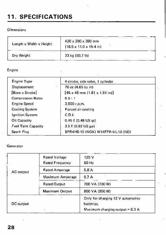
11. SPECIFICATIONS
Dimensions
Length x Width x Height 420 x 280 x 390 mm
(16.5 x 11.0 x 15.4 in)
Dry Weight 23 kg (50.7 lb)
I
Engine
Engine Type
Displacement
[Bore x Stroke]
Compression Ratio
Engine Speed
Cooling System
Ignition System
Oil Capacity
.Fuel Tank Capacity
Spark Plug
Generator
T AC output
4-stroke, side valve, 1 cylinder
76 cc (4.65 cu in)
[46 x 46 mm (1.81 x 1.81 in)]
6.0 : 1
3.600 r.p.m.
Forced air cooling
C.D.I.
0.45 II (0.48 US qt)
3.5 9 (0.92 US gal)
BPR4HS10 (NGK) W14FPRULlO (ND)
Rated Voltage 120 v
Rated Frequency 60 Hz
Rated Amperage 5.8 ‘A
Maximum Amperage 6.7A
Rated Output 700 VA (700 W)
1 Maximum Output 1 800 VA (800 W)
DC output
Only for charging 12 V automotive
batteries.
Maximum charging output = 8.3 A
28
12. WARRANTY SERVICE
Owner Satisfaction
Your satisfaction and goodwill are important to your dealer and to us. All Honda warranty details are explained in the Distributor’s Limited Warranty. Normally, any problems concerning the product will be handled by your dealer’s service department. If you have a warranty problem that has not been handled to your satisfaction, we suggest .you take the following action:
l Discuss your problem with a member of dealership management. Often complaints can be quickly resolved at that level. If the problem has already been reviewed with the Service Manager, contact the owner of the dealership or the General Manager.
l If your problem still has not been resolved to your satisfaction, contact the Power Equipment Customer Relations Department of American Honda Motor Co., Inc.
American Honda Motor Co., Inc. Power Equipment Customer Relations Department P-0. Box 50 Gardena, California 90247-0805 Telephone: (213) 604-2400
We will need the following information in order to assist you:
- Your name, address, and telephone number - Product model and serial number - Date of purchase - Dealer name and address - Nature of the problem
After reviewing all the facts involved, you will be advised of what action can be taken. Please bear in mind that your problem will likely be resolved at the dealership, using the dealer’s facilities, equipment, and personnel, so it is very important that your initial contact be with the dealer.
Your purchase of a Honda product is greatly appreciated by both your dealer and American Honda Motor Co., Inc. We want to assist you in every way possible to assure.your complete satisfaction with your purchase. 1
Current customer service contact information: United States, Puerto Rico, and U.S. Virgin Islands: Honda Power Equipment dealership personnel are trained professionals. They should be able to answer any question you may have. If you encounter a problem that your dealer does not solve to your satisfaction, please discuss it with the dealership's management. The Service Manager or General Manager can help. Almost all problems are solved in this way.
If you are dissatisfied with the decision made by the dealership's management, contact the Honda Power Equipment Customer Relations Office. You can write:
American Honda Motor Co., Inc. Power Equipment Division Customer Relations Office 4900 Marconi Drive Alpharetta, GA 30005-8847
Or telephone: (770) 497-6400 M-F, 8:30 am - 7:00 pm EST
When you write or call, please provide the following information:
• Model and serial numbers
• Name of the dealer who sold the Honda power equipment to you
• Name and address of the dealer who services your equipment
• Date of purchase
• Your name, address, and telephone number
• A detailed description of the problem

MEMO
30

MEMO
31


![Community Health Center Power Outage Exercise Plan (ExPlan) · Section 4: Conclusion 1 [Jurisdiction] [Protective Marking] Community Health Center . Power Outage Exercise Plan (ExPlan)](https://img.pdfslide.us/doc/110x75/5c6a940609d3f2310b8ccfa3/community-health-center-power-outage-exercise-plan-explan-section-4-conclusion.jpg)