Embed Size (px)
Citation preview
OPERATION MANUAL
English February 2006
1st Edition Rev 1.0.0 © Copyright 2006 Changzhou Tonghui Electronic Co., Ltd.
All rights reserved.
TH2821B Portable LCR Meter
TH2821B OPERATION MANUAL
2
Contents
Contents ........................................................... 2 How to Contact Us....................................... 3 Incoming Inspection..................................... 4 Notes on Use............................................... 5 Warranty: ................................................... 6
Chapter 1 Overview ........................................... 7 1.1 Introduction .......................................... 7 1.2 Main Functions ...................................... 7 1.3 Specifications ........................................ 8 1.4 Environment Requirements .................. 10
Chapter 2 Panel Illustration ............................. 11 2.1 LCD Display Illustration ........................ 11 2.2 Keyboard Illustration ........................... 13
Chapter 3 Operation ........................................ 14 3.1 Power on............................................. 14 3.2 How to operate ................................... 15
3.2.1 Key Functions ............................ 15 3.3 Battery Replacement ........................... 21 3.4 Clearing Instruction ............................. 22
Appendix ......................................................... 23
TH2821B OPERATION MANUAL
3
How to Contact Us
Changzhou Tonghui Electronic Co., Ltd. Address: No. 3, Tianshan Road, New District,
Changzhou, Jiangsu, China Tel: 0086-519-5132222, 5113342, 5109592 Fax: 0086-519-5109972 http://www.tonghui.com.cn http://www.tonghui.cn Email: [email protected]
TH2821B OPERATION MANUAL
4
Incoming Inspection
Inspect the shipping container for damage. The contents of the shipment should be listed as follows. If the contents are incomplete, if there is damage or defect, please contact our company or your nearest Sales and Service Office.
Accessories
TH26028 DC Power Adapter 1 TH26027 4 terminal Kelvin test clip leads 1 1604A 9V battery 1
User Manual 1 Options TH26029 SMD component test fixture
TH2821B OPERATION MANUAL
5
Notes on Use
This meter is only for indoor use. Turn off the TH2821B while switching the power supply
between battery and DC adapter or replacing the battery.
Although internal circuit protection is provided, DC voltage or current may damage TH2821B. Before you measure a capacitor, be sure the capacitor is fully discharged.
Take out the battery when the meter is not in use for more than 3 months.
A single standard 9V battery can be used for the power supply. TH2821B will not work normally when battery voltage is less than 6V.
The 12V AC to DC adaptor is recommended to be used for TH2821B power supply.
Perform Open and Short corrections for accurate measurement especially when test fixture is changed.
The functions locked with password are not accessible by users.
TH2821B OPERATION MANUAL
6
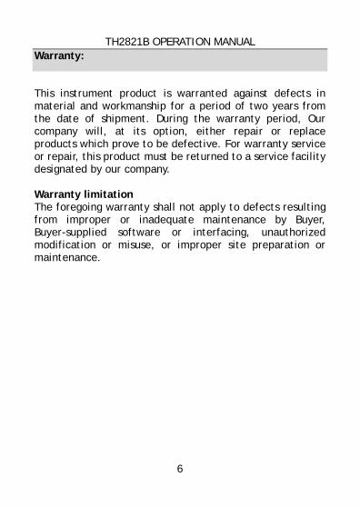
Warranty:
This instrument product is warranted against defects in material and workmanship for a period of two years from the date of shipment. During the warranty period, Our company will, at its option, either repair or replace products which prove to be defective. For warranty service or repair, this product must be returned to a service facility designated by our company. Warranty limitation The foregoing warranty shall not apply to defects resulting from improper or inadequate maintenance by Buyer, Buyer-supplied software or interfacing, unauthorized modification or misuse, or improper site preparation or maintenance.
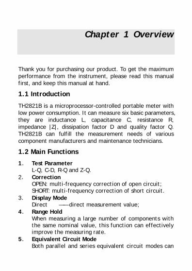
Chapter 1 Overview
Thank you for purchasing our product. To get the maximum performance from the instrument, please read this manual first, and keep this manual at hand.
1.1 Introduction
TH2821B is a microprocessor-controlled portable meter with low power consumption. It can measure six basic parameters, they are inductance L, capacitance C, resistance R, impedance |Z|, dissipation factor D and quality factor Q. TH2821B can fulfill the measurement needs of various component manufacturers and maintenance technicians.
1.2 Main Functions
1. Test Parameter L-Q, C-D, R-Q and Z-Q.
2. Correction OPEN: multi-frequency correction of open circuit; SHORT: multi-frequency correction of short circuit.
3. Display Mode Direct —— direct measurement value;
4. Range Hold When measuring a large number of components with the same nominal value, this function can effectively improve the measuring rate.
5. Equivalent Circuit Mode Both parallel and series equivalent circuit modes can
TH2821B OPERATION MANUAL
8
be obtained. 6. Data Hold
This function can be used to freeze the current display value.
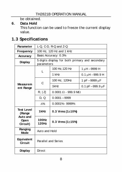
1.3 Specifications
Parameter L-Q, C-D, R-Q and Z-Q
Frequency 100 Hz, 120 Hz and 1 kHz
Accuracy Basic Accuracy: 0.3%
Display 5 digits display for both primary and secondary parameters
100 Hz,120 Hz 1 µH – 9999 H L
1 kHz 0.1 µH – 999.9 H
100 Hz, 120Hz 1 pF – 9999 µF C
1kHz 0.1 pF – 999.9 µF
R, |Z| 0.0001 Ω - 999.9 MΩ
D, Q 0.0001 – 9999
Measurement Range
∆% 0.0001% - 9999%
1kHz 0.3 Vrms (1±10%) Test Level (Range
Auto and Open
Circuit) 100Hz 120Hz 0.3 Vrms (1±15%)
Ranging Mode Auto and Hold
Equivalent Circuit Parallel and Series
Display Direct
TH2821B OPERATION MANUAL
9
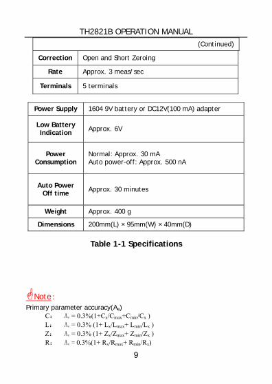
(Continued)
Correction Open and Short Zeroing
Rate Approx. 3 meas/sec
Terminals 5 terminals
Power Supply 1604 9V battery or DC12V(100 mA) adapter
Low Battery Indication Approx. 6V
Power Consumption
Normal: Approx. 30 mA Auto power-off: Approx. 500 nA
Auto Power Off time Approx. 30 minutes
Weight Approx. 400 g
Dimensions 200mm(L) × 95mm(W) × 40mm(D)
Table 1-1 Specifications
Note: Primary parameter accuracy(Ae)
C: Ae = 0.3%(1+Cx/Cmax+Cmin/Cx ) L: Ae = 0.3% (1+ Lx/Lmax+ Lmin/Lx ) Z: Ae = 0.3% (1+ Zx/Zmax+ Zmin/Zx ) R: Ae = 0.3%(1+ Rx/Rmax+ Rmin/Rx)
TH2821B OPERATION MANUAL
10
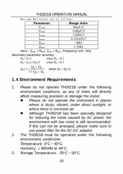
Max and Min values are as follows:
Parameter Range Auto Cmax 80µF/f Cmin 150pF/f Lmax 159H/f Lmin 0.32mH/f Zmax 1MΩ Zmin 1.59Ω
Here:Zmax = Rmax; Zmin = Rmin, Frequency unit: kHz. Secondary parameter accuracy
De= Ae/3 when Dx ≤0.1 De= Ae(1+Dx)/3 when Dx>0.1
Qe=ex
exDQ
DQ×
×±
m1 when Qx·De<1
1.4 Environment Requirements
1. Please do not operate TH2821B under the following environment conditions, as any of them will directly affect measuring precision or damage the meter:
Please do not operate the instrument in places where is dusty, vibrant, under direct sunlight, or where there is corrosive air.
Although TH2821B has been specially designed for reducing the noise caused by AC power, the environment with low noise is still recommended. If this can not be arranged, please make sure to use power filter for the AC-DC adaptor.
2. The TH2821B must be operated under the following environment conditions: Temperature: 0°C ~ 40°C, Humidity: ≤ 90% RH at 40°C.
3. Storage Temperature: -25°C ~ 50°C.
TH2821B OPERATION MANUAL
11
Chapter 2 Panel Illustration
2.1 LCD Display Illustration
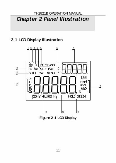
Figure 2-1 LCD Display
TH2821B OPERATION MANUAL
12
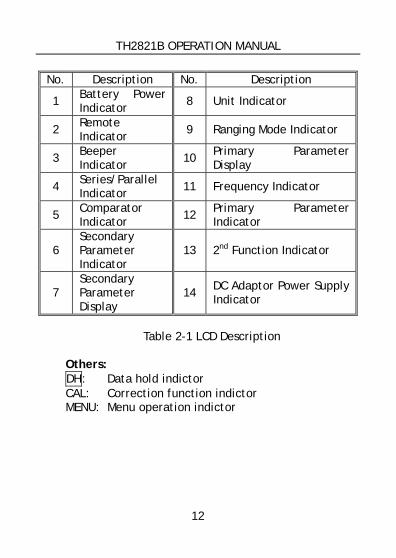
No. Description No. Description
1 Battery Power Indicator 8 Unit Indicator
2 Remote Indicator 9 Ranging Mode Indicator
3 Beeper Indicator 10 Primary Parameter
Display
4 Series/Parallel Indicator 11 Frequency Indicator
5 Comparator Indicator 12 Primary Parameter
Indicator
6 Secondary Parameter Indicator
13 2nd Function Indicator
7 Secondary Parameter Display
14 DC Adaptor Power Supply Indicator
Table 2-1 LCD Description
Others: DH: Data hold indictor CAL: Correction function indictor MENU: Menu operation indictor
TH2821B OPERATION MANUAL
13
2.2 Keyboard Illustration
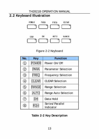
Figure 2-2 Keyboard
No. Key Function
1 POWER Power On/Off
2 PARA Parameter Selection
3 FREQ Frequency Selection
4 CLEAR CLEAR Selection
5 RANGE Range Selection
6 AUTO Range Auto Selection
7 DH Data Hold
8 EQU Series/Parallel Indicator
Table 2-2 Key Description
TH2821B OPERATION MANUAL
14
Chapter 3 Operation
3.1 Power on
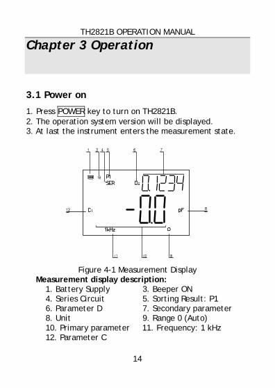
1. Press POWER key to turn on TH2821B. 2. The operation system version will be displayed. 3. At last the instrument enters the measurement state.
Figure 4-1 Measurement Display
Measurement display description: 1. Battery Supply 3. Beeper ON 4. Series Circuit 5. Sorting Result: P1 6. Parameter D 7. Secondary parameter 8. Unit 9. Range 0 (Auto) 10. Primary parameter 11. Frequency: 1 kHz 12. Parameter C
TH2821B OPERATION MANUAL
15
3.2 How to operate
3.2.1 Key Functions
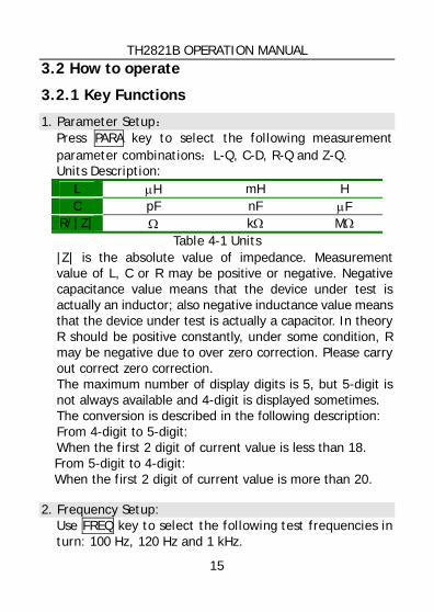
1. Parameter Setup: Press PARA key to select the following measurement parameter combinations:L-Q, C-D, R-Q and Z-Q. Units Description:
L µH mH H C pF nF µF
R/|Z| Ω kΩ MΩ Table 4-1 Units
|Z| is the absolute value of impedance. Measurement value of L, C or R may be positive or negative. Negative capacitance value means that the device under test is actually an inductor; also negative inductance value means that the device under test is actually a capacitor. In theory R should be positive constantly, under some condition, R may be negative due to over zero correction. Please carry out correct zero correction. The maximum number of display digits is 5, but 5-digit is not always available and 4-digit is displayed sometimes. The conversion is described in the following description: From 4-digit to 5-digit: When the first 2 digit of current value is less than 18. From 5-digit to 4-digit: When the first 2 digit of current value is more than 20.
2. Frequency Setup: Use FREQ key to select the following test frequencies in turn: 100 Hz, 120 Hz and 1 kHz.
TH2821B OPERATION MANUAL
16
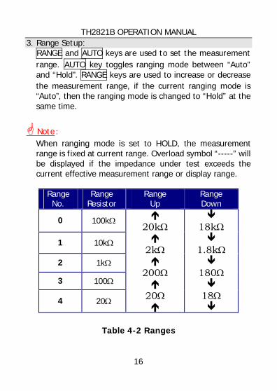
3. Range Setup: RANGE and AUTO keys are used to set the measurement range. AUTO key toggles ranging mode between “Auto” and “Hold”. RANGE keys are used to increase or decrease the measurement range, if the current ranging mode is “Auto”, then the ranging mode is changed to “Hold” at the same time.
Note: When ranging mode is set to HOLD, the measurement range is fixed at current range. Overload symbol “-----” will be displayed if the impedance under test exceeds the current effective measurement range or display range.
Range No.
Range Resistor
Range Up
Range Down
0 100kΩ
1 10kΩ
2 1kΩ
3 100Ω
4 20Ω
20kΩ
2kΩ
200Ω
20Ω
18kΩ
1.8kΩ
180Ω
18Ω
Table 4-2 Ranges
TH2821B OPERATION MANUAL
17
Note: How to calculate the measurement range Example: Assume capacitance C=210pF, dissipation D=0.0010 and test frequency f=1 kHz. Solution:
Ω≈××××
=≈
+=
− 9.7571021010001416.32
12
12
1
9X
X
XXX
fCZ
fCjRZ
π
π
From the Table 4-2, we can get the correct measurement range is No. 2.
4. Data Hold
Press DH key to freeze the display, press DH key again to release.
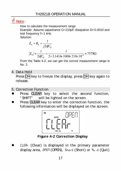
5. Correction Function
Press CLEAR key to select the second function, “SHIFT” will be lighted on the screen.
Press CLEAR key to enter the correction function, the following information will be displayed on the screen.
Figure 4-2 Correction Display
Clear (Clear) is displayed in the primary parameter
display area, OpeN (OPEN), Short (Short) or Quit (Quit)
TH2821B OPERATION MANUAL
18
will be displayed in the secondary parameter display area.
Note: OpeN (OPEN), Short (Short) and Quit (Quit) are selected and displayed automatically by the meter according to the impedance value of the device under test.
Press any key to cancel the correction operation and return to the measurement state. Press CLEAR key to start the correction measurement.
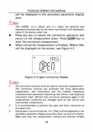
When correction measurement is finished, PASS or FAIL will be displayed on the screen, see Figure 4-3
Figure 4-3 Open correction Passed
Note: 1. The correction function must be used for accurate measurement.
The correction function can eliminate the stray admittance (capacitance, and inductance) and the residual impedance (resistance and reactance) induced by test fixture, test leads and instrument itself. Perform the correction operation again if the measurement conditions are changed such as test fixture and environment temperature.
2. It is recommended to perform the open and short correction at the same time.
3. During short correction period, FAIL (FAIL) will be displayed in the secondary parameter display area when short correction is failed. Make sure that the measurement contacts are shorted reliably
TH2821B OPERATION MANUAL
19
and perform the short correction again. 4. Th2821B measures the correction data at all frequency points and
all measurement ranges. The correction data is stored in the non-volatile memory. So you don’t have to perform the correction again, if the test conditions are not changed.
5. Open and short corrections are automatically selected by the instrument according to the impedance value under test. If there is a component in the fixture or if there is error with the instrument, Quit (Quit) will be displayed in the secondary parameter display area.
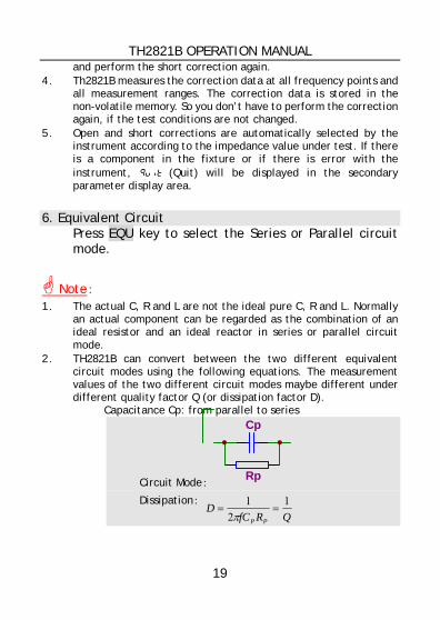
6. Equivalent Circuit
Press EQU key to select the Series or Parallel circuit mode.
Note: 1. The actual C, R and L are not the ideal pure C, R and L. Normally
an actual component can be regarded as the combination of an ideal resistor and an ideal reactor in series or parallel circuit mode.
2. TH2821B can convert between the two different equivalent circuit modes using the following equations. The measurement values of the two different circuit modes maybe different under different quality factor Q (or dissipation factor D).
Capacitance Cp: from parallel to series
Circuit Mode:
Cp
Rp
Dissipation:QRfC
DPP
12
1==
π
TH2821B OPERATION MANUAL
20
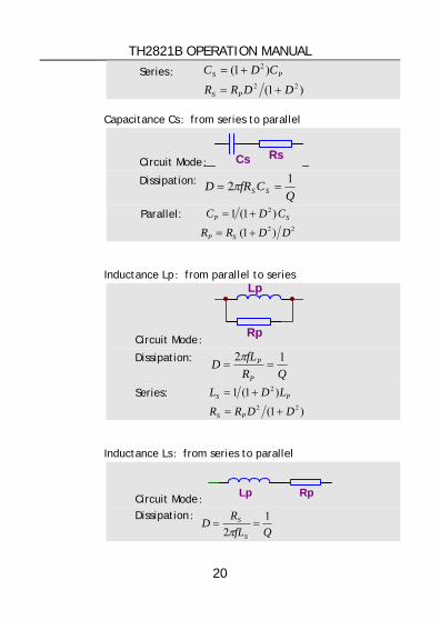
Series:
)1(
)1(22
2
DDRR
CDC
PS
PS
+=
+=
Capacitance Cs:from series to parallel
Circuit Mode: Cs Rs
Dissipation: Q
CfRD SS12 == π
Parallel: 22
2
)1(
)1(1
DDRR
CDC
SP
SP
+=
+=
Inductance Lp:from parallel to series
Circuit Mode:
Lp
Rp
Dissipation: QR
fLDP
P 12==
π
Series:
)1(
)1(122
2
DDRR
LDL
PS
PS
+=
+=
Inductance Ls:from series to parallel
Circuit Mode: Lp Rp Dissipation:
QfLR
DS
S 12
==π
TH2821B OPERATION MANUAL
21
Parallel: 22
2
)1(
)1(
DDRR
LDL
SP
SP
+=
+=
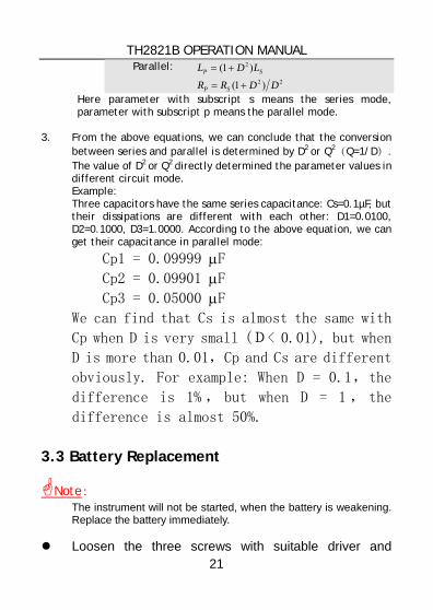
Here parameter with subscript s means the series mode, parameter with subscript p means the parallel mode.
3. From the above equations, we can conclude that the conversion
between series and parallel is determined by D2 or Q2(Q=1/D). The value of D2 or Q2 directly determined the parameter values in different circuit mode. Example: Three capacitors have the same series capacitance: Cs=0.1µF, but their dissipations are different with each other: D1=0.0100, D2=0.1000, D3=1.0000. According to the above equation, we can get their capacitance in parallel mode:
Cp1 = 0.09999 µF Cp2 = 0.09901 µF Cp3 = 0.05000 µF We can find that Cs is almost the same with
Cp when D is very small (D< 0.01), but when
D is more than 0.01,Cp and Cs are different
obviously. For example: When D = 0.1,the
difference is 1% , but when D = 1 , the
difference is almost 50%.
3.3 Battery Replacement
Note: The instrument will not be started, when the battery is weakening. Replace the battery immediately.
Loosen the three screws with suitable driver and
TH2821B OPERATION MANUAL
22
remove the bottom cover. Replace the degraded battery with a new DC 9V
battery. Model 1604, 006P or other equivalent battery must be
used. Alkaline battery is recommended. If the instrument is not in use for more than three
months, if the external DC adapter is always be used, please take out the battery.
Close the bottom cover. The degraded battery must be disposed of properly.
3.4 Clearing Instruction
To clean the instrument, use a soft cloth slightly dipped in water. Do not spray cleanser directly onto the instrument, since it may leak into the cabinet and cause damage. Do not use chemicals containing benzine, alcohol or aromatic hydrocarbons.
TH2821B OPERATION MANUAL
23
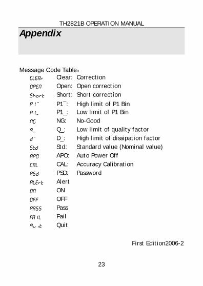
Appendix
Message Code Table: clear Clear: Correction
OpeN Open: Open correction
short Short: Short correction
P1~ P1—: High limit of P1 Bin P1_ P1_: Low limit of P1 Bin
Mg NG: No-Good
Q_ Q_: Low limit of quality factor
D~ D_: High limit of dissipation factor
Std Std: Standard value (Nominal value)
ApO APO: Auto Power Off
Cal CAL: Accuracy Calibration
Psd PSD: Password
Alert Alert
OM ON
Off OFF
pass Pass
faIl Fail
Quit Quit
First Edition2006-2