Embed Size (px)
Citation preview

40th Anniversary Edition
DATABASE PROCESSING Fundamentals, Design, and Implementation
15th Edition
David M. Kroenke | David J. Auer | Scott L. Vandenberg | Robert C. Yoder
Online Appendix B
Getting Started with Systems Analysis and Design
Database Processing (15th Edition) Appendix B Getting Started with Systems Analysis and Design
B-2
Appendix B – 10 9 8 7 6 5 4 3 2 1 ISBN 10: 0-13-480274-8 ISBN 13: 978-0-13-480274-9
330 Hudson Street | New York, NY 10013
Database Processing (15th Edition) Appendix B Getting Started with Systems Analysis and Design
B-3
Chapter Objectives
• To understand information systems
• To understand business processes
• To understand and be able to apply the systems development life cycle (SDLC) model
• To understand business process modeling using Business Process Modeling Notation (BPMN)
• To be able to gather data and information during requirements analysis
• To understand use cases
• To understand business rules
• To be able to create a user requirements document (URD)
• To be able to create a statement of work (SOW)
• To understand how the topics in this appendix link to Database Processing (15th Edition)

Database Processing (15th Edition) Appendix B Getting Started with Systems Analysis and Design
B-4
What Is the Purpose of This Appendix?
This appendix is intended to supplement David M. Kroenke, David J. Auer, Scott L. Vandenberg, and
Robert C. Yoder, Database Processing: Fundamental, Design, and Implementation (15th edition) (Upper
Saddle River, NJ: Prentice Hall, 2018) [referred to hereinafter as DBP].
In many college IT and MIS curriculums, it is normal for the class on database concepts and processing to
follow a class on systems analysis and design, and therefore DBP covers only those areas of information
system development appropriate to a database class. However, we have found that in other cases
students taking the database class have not had a systems analysis and design course, and therefore
don’t know some material that is needed to put the work in DBP into the proper context.
This appendix provides a brief introduction to systems analysis and design, and should be sufficient to
support a standalone course in database concepts and processing. For a complete discussion of the
topic, consult a text such as Joseph Valacich, Joey George, and Jeff Hoffer, Essentials of Systems Analysis
and Design (6th edition) (Upper Saddle River, NJ: Prentice Hall, 2015).
What Is Information?
In business, as in life, we often need to make a decision—what action should we take in our current
situation? In order to make a decision, we need information upon which to base that decision. Let’s
define data as recorded facts and numbers. Based on this definition, we can now define1 information
as:
• Knowledge derived from data.
• Data presented in a meaningful context.
• Data processed by summing, ordering, averaging, grouping, comparing, or other similar
operations.
Thus, before making a decision, we need to gather data and extract whatever information we can from
that data.
1 These definitions are from David M. Kroenke and Randall J Boyles's books: Using MIS (10th ed.) (Upper Saddle River, NJ: Prentice Hall, 2018) and Experiencing MIS (7th ed.) (Upper Saddle River, NJ: Prentice Hall, 2017). See these books for a full discussion of these definitions, as well as a discussion of a fourth definition, "a difference that makes a difference." The material in this appendix draws heavily on material presented in these two books. This is done to maintain continuity between the Kroenke and Boyles MIS texts and the Kroenke, Auer, Vandenberg, and Yoder database books Database Concepts (8th edition) (Upper Saddle River, NJ: Prentice Hall, 2017) and Database Processing: Fundamentals, Design and Implementation (15th edition) (Upper Saddle River, NJ: Prentice Hall, 2018). For more detailed information on the topics discussed in this appendix, please see either of the Kroenke MIS books.

Database Processing (15th Edition) Appendix B Getting Started with Systems Analysis and Design
B-5
Figure B-1 — The Five Component Information System Framework
What Is an Information System?
If we define a system as a set of components that interact to achieve some purpose or goal, then an
information system is a system that has the goal of producing information. While information systems
do not necessarily have to use computers, our discussion will include computers (after all, this is a book
about database systems that run on computers!). We can picture a computer-based information
system, which we will hereinafter refer to as simply an information system, as having five components:
computer hardware, software, data, procedures, and people. These components are illustrated in Figure
B-1.
Information systems must be developed and used to help businesses reach their goals and objectives,
and their function is to support an organization’s competitive strategy and help create a competitive
advantage.
What Is a Competitive Strategy?
Every company must develop a competitive strategy, which is the company’s organized response to the
industry structure of the industry in which it operates, and, thus, how to compete within that structure.
According to Porter’s five forces model,2 the structure of an industry is determined by relative strength
or weakness of:
• The bargaining power of customers: Can the industry’s customers influence the industry?
• The availability (“threat”) of substitutable products: What other products do competitors
have?
• The bargaining power of suppliers: Can the industry’s suppliers influence the industry?
• The ease (“threat”) of new competitors entering the industry: How easily can a new company
get a start in the industry?
• The rivalry between competitors: How many competitors are there, and how much do they
really compete?
How Does a Company Organize Itself Based on Its Competitive Strategy?
Once the company has a competitive strategy, it will organize the company’s business activities to
implement that strategy and to create a competitive advantage for the firm. Business activities consist
2 Michael Porter, Competitive Strategy: Techniques for Analyzing Industries and Competitors (New York: Free Press, 1980). Also see David Kroenke's discussion of the model in David M. Kroenke and Randall J. Boyle's books Using MIS (10th edition) (Upper Saddle River, NJ: Prentice Hall, 2018) and Experiencing MIS (7th edition) (Upper Saddle River, NJ: Prentice Hall, 2017).

Database Processing (15th Edition) Appendix B Getting Started with Systems Analysis and Design
B-6
of primary activities and support activities. Michael Porter3 defines the primary activities or operational
activities of a business as:
• Inbound logistics: receiving, storing, and distributing product inputs.
• Manufacturing operations: transforming inputs into the final product.
• Outbound logistics: collecting, storing, and distributing the product to buyers.
• Sales and marketing: convincing customers to buy the product and selling it to them.
• Customer service: assisting the customers in their use of the product.
In addition to these operational activities, there are also additional support activities that, as the name
implies, support the operational activities. These include:
• Procurement: managing supplier relationships and buying the product inputs.
• Technology management: product research and development and new procedures, methods,
and techniques.
• Human resources management: managing employee resources.
• Firm infrastructure management: general management of the firm, including finance,
accounting, legal services, and government affairs.
To implement its competitive strategy, a business must organize these activities into business processes
that support that strategy.
What Is a Business Process?
A business process is a set of activities that transform inputs into outputs, as shown in Figure B-2. For
example, consider a simplified manufacturing process for a wheelbarrow. The parts needed to build the
wheelbarrows (the inputs or raw materials) are put together (the assembly activities) to create the
complete wheelbarrows (the outputs or finished goods). The input parts have been previously
Inputs Activities Outputs
Figure B-2 — A Generalized Business Process
Raw Materials
Inventory
Assembly
Activities
Finished Goods
Inventory
Figure B-3 — The Manufacturing Process
3 Michael Porter, Competitive Advantage: Creating and Sustaining Superior Performance (New York: Free Press,
1998). Also see the discussion of primary and support activities in David M. Kroenke and Randall J. Boyle's books Using MIS (10th edition) (Upper Saddle River, NJ: Prentice Hall, 2018) and Experiencing MIS (7th edition) (Upper Saddle River: Prentice Hall, 2017).

Database Processing (15th Edition) Appendix B Getting Started with Systems Analysis and Design
B-7
Outbound LogisticsManufacturing OperationsInbound Logistics
Raw Materials
Inventory
Assembly
Activities
Finished Goods
Inventory
Figure B-4 — The Manufacturing Process as It Overlays Porter’s Operational Activities
purchased and are stored in a raw materials inventory. These are the parts that are put into the
manufacturing process, and after the wheelbarrows are built, they are stored in a finished goods
inventory. Thus, the wheelbarrow manufacturing process can be illustrated as shown in Figure B-3.
Note that, as shown in Figure B-4, this process overlays Porter’s inbound logistics, manufacturing
operations, and outbound logistics operational activities. Other business processes may overlay other
sets of Porter’s activities.
How Do Information Systems Support Business Processes?
The manufacturing process shown in Figure B-3 does not necessarily include an information system—it
may represent only the basic physical system of individual parts being put together by workers into
wheelbarrows. However, we can introduce an information system to support this process by adding a
computer application to track the raw materials inventory and finished goods inventory. As shown in
Figure B-5, the Inventory Control Application:
• Updates the raw materials inventory by subtracting the parts used in the assembly activities.
• Updates the finished goods inventory by adding each new wheelbarrow as it is completed.
Figure B-5 illustrates that information systems exist to support business processes—they are not the
business processes themselves.
Do Information Systems Include Processes?
A business process can be generalized as a conceptual process chain of input process output.
Information systems include such processes. For example, the inventory control application shown in
Figure B-5 will include these steps as:
• Input data: Using a computer on-screen form, a user will input data into the system, such as
how many parts have been taken out of the raw materials inventory to build a wheelbarrow.
• Process: Another user may query the raw materials database to determine how many of each
part remain in the raw materials inventory.

Database Processing (15th Edition) Appendix B Getting Started with Systems Analysis and Design
B-8
Figure B-5 — The Manufacturing Process with Supporting Information System
• Output: The answer to the query will be presented to the requesting user as a report detailing
the current status of the parts in the raw materials inventory.
The output of this application may then become the input to another process. For example, if the
number of wheelbarrow wheels in the raw materials inventory is determined to be too low on the basis
of the report, this may start a parts order process to replenish the raw materials inventory of wheels.
Do We Have to Understand Business Processes in Order to Create Information
Systems?
Because the purpose of an information system is to support a business process, we have to understand
the business process before we can design the information system. To do this, we study the process and
document it using business process modeling. After documenting the process, we will generally
understand something about what sort of information system is needed to support the process, and we
can then use systems analysis and design methodology to create and maintain the needed information
system.
What Is Systems Analysis and Design?
Systems analysis and design is the process of creating and maintaining information systems. The classic
methodology used in systems analysis and design to develop information systems is called the systems
development life cycle (SDLC).

Database Processing (15th Edition) Appendix B Getting Started with Systems Analysis and Design
B-9
What Are the Steps in the SDLC?
There are different interpretations or conceptualizations of the SDLC, each of which uses a different
number of steps. We will use the same set of five steps used by Kroenke4:
1. System definition
2. Requirements analysis
3. Component design
4. Implementation
5. System maintenance
These steps, together with the business process that determines the need for the information system to
be created and the users of that system, are shown in Figure B-6. Each step should result in one or more
deliverables, such as documents, designs, prototypes, data models, database designs, Web screens, and
so on.
Figure B-6 — The SDLC in Use
4 See the discussion in David M. Kroenke and Randall J. Boyle's books Using MIS (10th edition) (Upper Saddle River,
NJ: Prentice Hall, 2018) and Experiencing MIS (7th edition) (Upper Saddle River, NJ: Prentice Hall, 2017).

Database Processing (15th Edition) Appendix B Getting Started with Systems Analysis and Design
B-10
Figure B-7 — Gantt Chart of the WBS of the System Definition Step of a Project
The System Definition Step
The system definition step is a process that starts with the need for an information system to support a
business process as its input and produces a project plan as its output. During this process, we will need
to:
• Define the information system project goals and scope.
• Assess the feasibility of the project (financial [cost], temporal [schedule], technical, organizational).
• Form the project team.
• Plan the project (specify tasks, assign personnel, determine task dependencies, set schedules).
A deliverable for system definition is a project plan, which should include a work-breakdown schedule (WBS) implemented as a Gantt chart to include task durations and dependencies. An example is shown in Figure B-7, and was created in Microsoft Visio 2016. Other software, such as Microsoft Project 2016, can also be used.
The Requirements Analysis Step
The requirements analysis step is a process that starts with the project plan as its input and produces a
set of approved user requirements as its output. During this process, we will need to:
• Conduct user interviews.
• Evaluate existing systems.
• Determine needed new forms/reports/queries.
• Identify needed new application features and functions.
• Consider security.
• Create the data model.
• Consider the five components of an information system—hardware, software, data, procedures,
and people.
A deliverable for requirements analysis is an approved set of user requirements as a user requirements
document (URD), and may include an approved statement of work (SOW). There are no set formats for
URDs and SOWs. Further, an SOW for an in-company project may be very different from an SOW
between a consultant and client. URDs and SOWs are discussed in more detail later in this appendix.

Database Processing (15th Edition) Appendix B Getting Started with Systems Analysis and Design
B-11
Note that another deliverable (which may be included in the SOW or other document) is a data model.
Data modeling is the subject of Chapter 5 in DBP, and is discussed in detail in that chapter. At this point,
simply note this connection between the SDLC methodology discussed in this appendix and Chapter 5 in
DBP.
The Component Design Step
The component design step is a process that starts with the approved user requirements as its input and
produces a final system design as its output. During this process, we will need to:
• Determine hardware specifications.
• Determine program (software) specifications.
• Create the database design.
• Design business procedures.
• Create job descriptions for business personnel.
A deliverable for component design is the documented system design. There is no set format for this
document, but note that it specifies what must be purchased (hardware and possibly software), what
must be created (the database), and how the business must adjust its operations (procedures and job
responsibilities) to actually implement that information system.
Note that one deliverable in the system design is a database design. Database design is the subject of
Chapter 6 in DBP, and is discussed in detail in that chapter. At this point, simply note this connection
between the SDLC methodology discussed in this appendix and Chapter 6 in DBP.
The Implementation Step
The implementation step is a process that starts with the final system design as its input and produces a
final system as its output. During this process, we will need to:
• Build system components.
• Conduct component tests.
• Integrate the components.
• Conduct integrated component tests.
• Convert to the new system.
The deliverable for the implementation step is the installed and functioning information system that
was needed by the business process. In this step, we implement the elements of the final system design,
as shown in Figure B-8.
Note that one deliverable in implementation is a functioning database. Creating database structures and
populating them with data is the subject of Chapter 7 in the DBP text, and is discussed in detail in that
chapter. At this point, simply note this connection between the SDLC methodology discussed in this
appendix and Chapter 7 in the text.

Database Processing (15th Edition) Appendix B Getting Started with Systems Analysis and Design
B-12
Figure B-8 — The SDLC Design and Implementation Steps for the Five Information System Components
The System Maintenance Step
The system maintenance step is a process that starts with the implemented system as its input and
produces an updated system or a request for system modification using the SDLC as its output. During
this process, we will need to:
• Update the system with patches, service packs, and new software releases.
• Record and prioritize requests for system changes or enhancements.
The deliverables for system maintenance include an updated system and the start of a new SDLC cycle
to enhance the information system. These are both common and typical events for any information
system.
What SDLC Details Do We Need to Know?
Now that we have defined business processes and the SDLC, we can take a detailed look at the steps
that are not already covered in DBP itself. The remainder of this appendix will provide a more detailed
discussion of SDLC topics. In particular, but not exclusively, we will focus on the requirements analysis
step because the component design step and implementation step details that we need to know are
covered in Chapters 4 and 5. Our topics will include:
• A discussion of Business Process Modeling Notation (BPMN).
• Determining project scope.
• Gathering data.
• Creating use cases.
• Determining business rules.
• Creating a user requirements document (URD).
• Creating a statement of work (SOW).

Database Processing (15th Edition) Appendix B Getting Started with Systems Analysis and Design
B-13
What Is Business Process Modeling Notation?
As discussed earlier in this appendix, business processes are the input to the SDLC. Information systems
are developed to support those business processes, so we need to study and document those processes
before we ever start systems analysis and design.
This study and documentation of business processes is referred to as business process modeling, and
business process modeling notation (BPMN) is a commonly used system for drawing business process
models. Because business process modeling is outside the scope of this book, we do not cover it in
detail.5
What Is Project Scope?
The Project Management Institute (http://www.pmi.org) defines project scope as “The work that needs
to be accomplished to deliver a product, service, or result with the specified features and functions.”6 A
formal statement of project scope is included in the statement of work (SOW) for the project, as
discussed later in this appendix. However, drafting the initial goals and scope of the project is a part of
the system definition step of the SDLC, and an initial scope statement is useful when considering how to
gather data during the requirements analysis step.
In particular, the scope statement will be useful in determining:
• The stakeholders in the project and appropriate representatives of each stakeholder group who
can be contacted for data and information.
• The likely types of forms and reports that already exist within the business.
• The likely types of business rules that already exist (either explicitly or implicitly) in the business.
How Do I Gather Data and Information about System Requirements?
The two common means of gathering data and information are user interviews and a review of existing
forms, reports, and any other documentation that may be available (flowcharts, step-by-step
instructions, etc.).
This may be an iterative process. For example, a user interview may also produce new forms or reports
that raise questions such that another interview with that user is needed. Similarly, a review of existing
documentation prior to a user interview may raise questions that can be resolved during the interview.
The data and information gathered during the requirements analysis step will provide matter for both
the SOW and the data model for the database in the information system.
5 For more information on business process modeling, see David M. Kroenke and Randall J. Boyle’s books, Using MIS (10th edition) (Upper Saddle River, NJ: Prentice Hall: 2018, Chapter 12) and Experiencing MIS (7th edition) (Upper Saddle River, NJ: Prentice Hall: 2017, Chapter Extension 18), and the Object Management Group’s Business Process Management Initiative Web page at http://www.bpmn.org/ . 6 A Guide to the Project Management Body of Knowledge (PMBOK Guide) — Fourth Edition. Project Management Institute, 2008, as quoted on Wikipedia at http://en.wikipedia.org/wiki/Scope_(project_management) .

Database Processing (15th Edition) Appendix B Getting Started with Systems Analysis and Design
B-14
How Do Use Cases Provide Data and Information About System Requirements?
Use cases are descriptions of the ways users will employ the features and functions of the new
information system. A use case consists of a description of the roles users will play when utilizing the
new system, together with descriptions of activity scenarios. Inputs provided to the system and outputs
generated by the system are defined. Sometimes dozens of such use cases are necessary. Use cases
provide sources of requirements and also can be used to validate the data model, database design, and
implementation.
Microsoft Visio 2016 can be used to draw Uniform Modeling Language (UML) use case diagrams. UML is
described at http://www.uml.org, and Microsoft Visio 2016 basics are covered in Appendix D. To open a
template for a UML use case diagram, search for UML Use Case to display the UML Use Case template,
and then click the UML Use Case template to select it. Click the Create button to create a new UML Use
Case drawing. This stencil can be used to draw use cases, as shown in Figure B-9.
Figure B-9 — The Microsoft Visio 2016 UML Use Case Diagram
The Shapes windows
The Define Shape Data dialog box
The HU-Use-Case-Diagram document name
The HU-Use-Case-Diagram document

Database Processing (15th Edition) Appendix B Getting Started with Systems Analysis and Design
B-15
The Highline University Database
We will take a look at an example of data and information gathering as part of the development of a
data model to illustrate these concepts. Highline University is a four-year undergraduate school located
in the Puget Sound region of Washington State.7 Highline University, like many colleges and universities
in the Pacific Northwest, is accredited by the Northwest Commission on Colleges and Universities
(NWCCU). The Highline University case is also discussed in Chapter 5 in the DBP text.
Like all the colleges and universities accredited by the NWCCU, Highline University must be reaccredited
at approximately 5-year intervals. Additionally, the NWCCU requires annual status update reports.
Highline University is made up of five colleges—the College of Business, the College of Social Sciences
and Humanities, the College of Performing Arts, the College of Sciences and Technology, and the College
of Environmental Sciences. Jan Smathers is the president of Highline University, and Dennis Endersby is
the provost (A provost is a vice president of academics—the deans of the colleges report to the
provost).
In order to facilitate providing required accreditation and annual status reports to the NWCCU,
President Smathers and Provost Endersby have decided that the current manual process of preparing
the reports needs to be replaced by an online information system. They have appointed a task force to
implement this information system.
Dr. Christina Eastman, a professor in the Department of Computer Science in the College of Sciences and
Technology, has been appointed to the task force. Given Christina’s expertise in systems analysis and
design and database systems, the task force has chosen her as the project manager. The task force has
also drafted an initial project scope statement:
The Highline University NWCCU Reporting System will acquire, store, and manage the data needed
to comply with the NWCCU accreditation and annual status reporting requirements. It will track data
on college administration, college staffing, college majors, and advising of those majors. It will
prepare, display, and print reports that comply with the NWCCU standards and formats.
Christina and her colleagues identify the stakeholders in this process as the Office of the President, the
Office of the Provost, the deans, and the chairs and administrative staff of each college and of each
department within each college. Since Provost Endersby is responsible for preparing the NWCCU reports
for President Smathers, Christina interviews Provost Endersby and gathers examples of existing reports
and other relevant documents. She and other members of the task force also interview:
• The dean of each college—Example: Dr. Mary B. Jefferson, Dean of the College of Business.
• The chairperson of each department—Example: Dr. Nathaniel D. Brammer, Chairperson of the
Information Systems Department of the College of Business.
• Selected professors who advise student majors—Example: Dr. Paul D. Jones of the Information
Systems Department of the College of Business.
7 Highline University is a fictional university, and should not be confused with Highline Community College located in Des Moines, WA. Any resemblance between Highline University and Highline Community College is unintentional and purely coincidental.
Database Processing (15th Edition) Appendix B Getting Started with Systems Analysis and Design
B-16
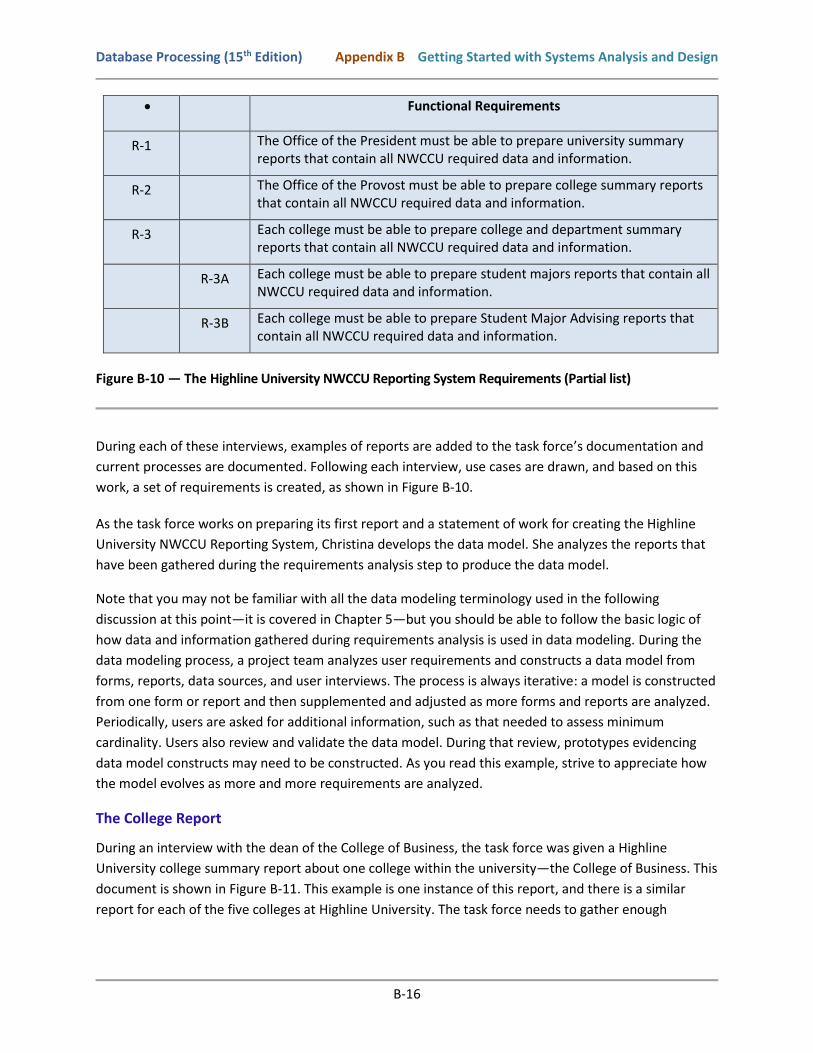
• Functional Requirements
R-1 The Office of the President must be able to prepare university summary reports that contain all NWCCU required data and information.
R-2 The Office of the Provost must be able to prepare college summary reports that contain all NWCCU required data and information.
R-3 Each college must be able to prepare college and department summary reports that contain all NWCCU required data and information.
R-3A Each college must be able to prepare student majors reports that contain all NWCCU required data and information.
R-3B Each college must be able to prepare Student Major Advising reports that contain all NWCCU required data and information.
Figure B-10 — The Highline University NWCCU Reporting System Requirements (Partial list)
During each of these interviews, examples of reports are added to the task force’s documentation and
current processes are documented. Following each interview, use cases are drawn, and based on this
work, a set of requirements is created, as shown in Figure B-10.
As the task force works on preparing its first report and a statement of work for creating the Highline
University NWCCU Reporting System, Christina develops the data model. She analyzes the reports that
have been gathered during the requirements analysis step to produce the data model.
Note that you may not be familiar with all the data modeling terminology used in the following
discussion at this point—it is covered in Chapter 5—but you should be able to follow the basic logic of
how data and information gathered during requirements analysis is used in data modeling. During the
data modeling process, a project team analyzes user requirements and constructs a data model from
forms, reports, data sources, and user interviews. The process is always iterative: a model is constructed
from one form or report and then supplemented and adjusted as more forms and reports are analyzed.
Periodically, users are asked for additional information, such as that needed to assess minimum
cardinality. Users also review and validate the data model. During that review, prototypes evidencing
data model constructs may need to be constructed. As you read this example, strive to appreciate how
the model evolves as more and more requirements are analyzed.
The College Report
During an interview with the dean of the College of Business, the task force was given a Highline
University college summary report about one college within the university—the College of Business. This
document is shown in Figure B-11. This example is one instance of this report, and there is a similar
report for each of the five colleges at Highline University. The task force needs to gather enough

Database Processing (15th Edition) Appendix B Getting Started with Systems Analysis and Design
B-17
examples to form a representative sample of all the college reports. Here, assume that the report in
Figure B-11 is representative.
Examining the report, Christina finds data specific to the college—such as the name, dean, telephone
number, and campus address—and also facts about each department within the college. These data
suggest that the data model should have COLLEGE and DEPARTMENT entities with a relationship
between them, as shown in Figure B-12.
The relationship in Figure B-12 is non-identifying. This relationship is used because DEPARTMENT is not
ID-dependent, and, logically, a DEPARTMENT is independent of a COLLEGE. Christina cannot tell from
the report in Figure B-11 whether a department can belong to many colleges. To answer this question,
she needs to ask the users or look at other forms and reports.
Assume Christina knows from the users that a department belongs to just one college, and the
relationship is thus 1:N from COLLEGE to DEPARTMENT. The report in Figure B-11 does not show her the
minimum cardinalities. Again, she must ask the users. Assume Christina learns from the users that a
college must have at least one department, and a department must be assigned to exactly one college.
Figure B-11 — The Highline University Sample College Report
Figure B-12 — Data Model for the Sample College Report

Database Processing (15th Edition) Appendix B Getting Started with Systems Analysis and Design
B-18
The Department Report
The Department Report shown in Figure B-13 contains departmental data along with a list of the
professors who are assigned to that department. This report contains data concerning the department’s
campus address. Because these data do not appear in the DEPARTMENT entity in Figure B-12, Christina
needs to add them, as shown in Figure B-14. This is typical of the data modeling process. That is, entities
and relationships are adjusted as additional forms, reports, and other requirements are analyzed.
Figure B-14 also adds the relationship between DEPARTMENT and PROFESSOR. Christina initially
modeled this as an N:M relationship because a professor might have a joint appointment. Christina must
further investigate the requirements to determine whether joint appointments are allowed. If not, the
relationship can be redefined as a non-identifying 1:N relationship, as shown in Figure B-15.
Another possibility regarding the N:M relationship is that some attribute about the combination of a
professor and a department is missing. If so, then an association pattern is more appropriate. At
Highline University, suppose that Christina finds a report that describes the title and employment terms
for each professor in each department. Figure B-16 shows an entity for such a report, named
APPOINTMENT. Since this is an association pattern, APPOINTMENT is ID-dependent on both
DEPARTMENT and PROFESSOR.
A chairperson is a professor, so Christina makes another improvement to the model—she removes the
Chairperson data from DEPARTMENT and replaces it with a chairperson relationship. This has been done
in Figure B-17. In the Chairs/Chaired By relationship, the PROFESSOR is the parent entity. A professor
can be a chair of zero or one departments, and a department must have exactly one professor as chair.
Figure B-13 — The Highline University Sample Department Report

Database Processing (15th Edition) Appendix B Getting Started with Systems Analysis and Design
B-19
Figure B-14 — Data Model Using an N:M Relationship
Figure B-15 — Data Model Using a 1:N Relationship
Figure B-16 — Data Model Using an Association Pattern

Database Processing (15th Edition) Appendix B Getting Started with Systems Analysis and Design
B-20
Figure B-17 — Data Model Using an Association Pattern and a 1:1 Relationship
With the Chairs/Chaired By relationship, the attribute Chairperson is no longer needed in DEPARTMENT,
so Christina removes it. Normally, a chairperson has his or her office in the department office; if this is
the case, Phone, Building, and Room in DEPARTMENT duplicate Phone, Building, and OfficeNumber in
PROFESSOR. Consequently, it might be possible to remove Phone, Building, and Room from
DEPARTMENT. However, a professor may have a different phone from the official department phone,
and the professor may also have an office outside of the department’s office. Because of this possibility,
Christina leaves Phone, Building, and Room in DEPARTMENT.
The Department/Major Report
Figure B-18 shows a department report the task force obtained that shows the students who major in
that department. This report indicates the need for a new entity called STUDENT. Because students are
not ID-dependent on departments, the relationship between DEPARTMENT and STUDENT is non-
identifying, as shown in Figure B-19. Christina cannot determine the minimum cardinality from Figure B-
18, but based on task force interviews with users, she determines that a STUDENT must have a MAJOR
(we are not considering double majors in this model, as stated in BR-4 below), but no MAJOR need have
any students. Using the contents of this report as a guide, she also places the attributes StudentNumber,
StudentName, and Phone in STUDENT.
Note that there are two subtleties in this interpretation of the report in Figure B-18. First, observe that
Major’s Name was changed to StudentName when the attribute was placed in STUDENT. Christina did
this because StudentName is more generic. Major’s Name has no meaning outside the context of the
Major relationship. Second, the report heading in Figure B-18 has an ambiguity. Is the phone number for
the department a value of DEPARTMENT.Phone or a value of PROFESSOR.Phone? Christina or another
person on the task force needs to investigate this further with the users. Most likely, it is a value of
DEPARTMENT.Phone.

Database Processing (15th Edition) Appendix B Getting Started with Systems Analysis and Design
B-21
Figure B-18 — The Highline University Sample Department Student Report
Figure B-19 — Data Model with STUDENT Entity
The Student Acceptance Letter
Figure B-20 shows the acceptance letter that Highline University sends to its incoming students. The
data items in this letter that need to be represented in the data model are shown in boldface. In
addition to data concerning the student, this letter also contains data regarding the student’s major
department as well as data about the student’s adviser.
Christina can use this letter to add an Advises/Advised By relationship to the data model. However,
which entity should she consider to be the parent of this relationship? Because an adviser is a professor,
it is tempting to make PROFESSOR the parent. However, a professor acts as an adviser within the
context of a particular department. Therefore, Figure B-21 shows that Christina chose APPOINTMENT as
the parent of STUDENT. To produce the report in Figure B-20, the professor’s data can be retrieved by
accessing the related APPOINTMENT entity and then accessing that entity’s PROFESSOR parent. This
decision is not cut-and-dried, however. One can make a strong argument that the parent of the
relationship should be PROFESSOR.

Database Processing (15th Edition) Appendix B Getting Started with Systems Analysis and Design
B-22
Figure B-20 — The Highline University Sample Student Acceptance Letter
Figure B-21 — Data Model Using an Advises Relationship

Database Processing (15th Edition) Appendix B Getting Started with Systems Analysis and Design
B-23
According to this data model, a student has at most one adviser. Also, a student must have an adviser,
but no professor (via APPOINTMENT) has to advise any students. These constraints cannot be
determined from any of the reports shown and will need to be verified with the users. The acceptance
letter uses the title Mr. in the salutation. Therefore, Christina added a new attribute named Title to
STUDENT. Observe that this Title is different from the one in APPOINTMENT. This difference will need to
be documented in the data model to avoid confusion. Finally, because the student’s home address in
included in the acceptance letter, the new home address attributes were added to STUDENT.
However, the acceptance letter reveals another problem. The name of the student is Fred Parks, but so
far Christina has allocated only one name attribute, StudentName, in STUDENT. It is difficult to reliably
disentangle first and last names from a single attribute, so a better model is to have two attributes:
StudentFirstName and StudentLastName. Similarly, note that the adviser in this letter is Elizabeth
Johnson. So far, all professor names have been in the format Johnson, Elizabeth. To accommodate both
forms of name, Christina changes ProfessorName in PROFESSOR to the two attributes
ProfessorFirstName and ProfessorLastName. A similar change is necessary for DeanName.
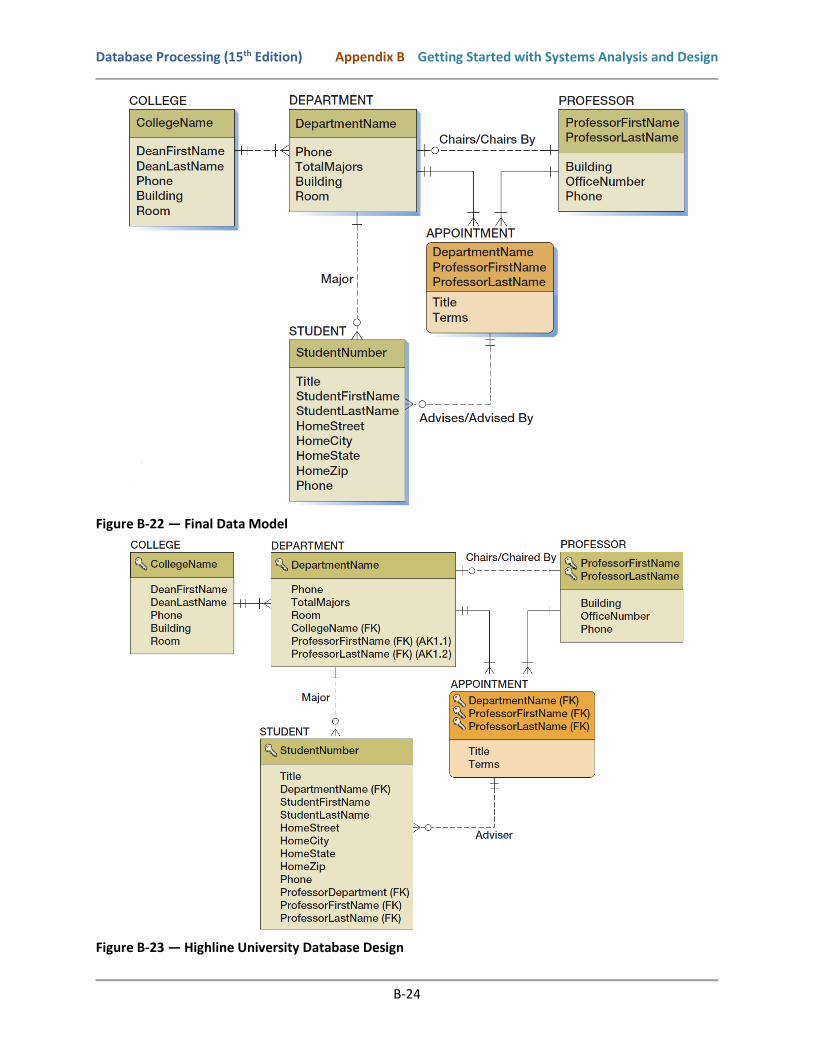
These changes are shown in Figure B-22, which is the final form of Christina’s data model. This section
should give you a feel for the nature of a data modeling project. Forms and reports are examined in
sequence, and the data model is adjusted as necessary to accommodate the knowledge gained from
each new form or report and the information from user interviews. It is very typical to revise the data
model many, many times throughout the data modeling process.
For the sake of completeness, Figure B-23 shows the Highline University data model converted into a
database design (database designs are discussed in Chapter 6) during the component design step of the
SDLC. This database design is the structure that will be created in a DBMS during the Implementation
step of the SDLC (note that the application that is built upon this database will have to ensure that the
values in DEPARTMENT.TotalMajors are correctly maintained when a student adds or drops the major.)
What Are Business Rules?
Business rules are constraints on database activities. Generally, such rules arise from business policy
and practice. For example, the following business rules could pertain to an academic database such as
the Highline University database:
Business Rules
BR-1 Students must declare a major before enrolling in any class.
BR-2 Graduate classes can be taken by juniors or seniors with a grade point average of 3.70 or greater.
BR-3 No adviser may have more than 25 advisees.
BR-4 Students may declare only one major.
Database Processing (15th Edition) Appendix B Getting Started with Systems Analysis and Design
B-24
Figure B-22 — Final Data Model
Figure B-23 — Highline University Database Design

Database Processing (15th Edition) Appendix B Getting Started with Systems Analysis and Design
B-25
What Is a User Requirements Document (URD)?
A deliverable for requirements analysis is an approved set of user requirements as a user requirements
document (URD). There is no set format for a URD.
Typically, a URD may contain:
• a table of contents
• a revision history
• an introduction
• a general description of the project (including project assumptions and dependencies)
• a data model
• functional requirements
• nonfunctional requirements (speed and time, capacity, and reliability)
• project delivery requirements
The purpose of a URD is to formalize the project team’s understanding of the users’ requirements so
that the users can review the document. Note that the data model for the database is presented as part
of the URD. This allows the data design to be reviewed and approved by the users. Based on the review,
the URD can be negotiated and revised until the document is approved by the users. At this point, the
project team has an approved set of project requirements with which to work.
What Is a Statement of Work (SOW)?
Deliverables for requirements analysis may include an approved statement of work (SOW). There is no
set format for an SOW, and an SOW for an in-company project may be very different for an SOW
between a consultant and client.
Typically, an SOW may contain descriptions of:
• A history of the problem or need that generated the project.
• An identification of the client for the work.
• An identification of who will do the work.
• The scope of the work to be done.
• The objectives of the work to be done.
• Any constraints on the work to be done.
• The location of the work (where the work will be done).
• A set of tasks with an associated timeline:
o An outline of the tasks that will make up the work to be done.
o The time period for the work (start date, finish date, details about how many hours may
be worked, etc.).
o A deliverables schedule.
• Criteria for determining whether the project has been successfully completed.
• A payment schedule.
• Signature blocks to record acceptance of the SOW by all parties.
Database Processing (15th Edition) Appendix B Getting Started with Systems Analysis and Design
B-26
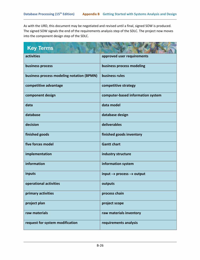
As with the URD, this document may be negotiated and revised until a final, signed SOW is produced.
The signed SOW signals the end of the requirements analysis step of the SDLC. The project now moves
into the component design step of the SDLC.
activities approved user requirements
business process business process modeling
business process modeling notation (BPMN) business rules
competitive advantage competitive strategy
component design computer-based information system
data data model
database database design
decision deliverables
finished goods finished goods inventory
five forces model Gantt chart
implementation industry structure
information information system
inputs input process output
operational activities outputs
primary activities process chain
project plan project scope
raw materials raw materials inventory
request for system modification requirements analysis

Database Processing (15th Edition) Appendix B Getting Started with Systems Analysis and Design
B-27
statement of work (SOW) support activities
system systems analysis and design
system definition system design
system maintenance systems development life cycle (SDLC)
UML use case Unified Modeling Language (UML)
updated system user requirements document (URD)
work breakdown schedule (WBS)
B-1. What is a decision?
B-2 What is data?
B-3 What is information?
B-4 What is a system? What is an information system?
B-5 What is a computer-based information system? Describe the five components of a computer
based information system.
B-6 What is a competitive strategy?
B-7 Describe Michael Porter’s five forces model.
B-8 Describe Michael Porter’s primary activities.
B-9 Describe Michael Porter’s support activities.
B-10 What is a business process?
B-11 How do information systems support business processes?
B-12 Describe how information systems include processes.
B-13 What is business process modeling?
B-14 What is systems analysis and design?
B-15 Describe the systems development life cycle (SDLC) model.
B-16 Define project scope.
B-17 What is a use case? How well does Microsoft Visio 2016 support modeling use cases?

Database Processing (15th Edition) Appendix B Getting Started with Systems Analysis and Design
B-28
B-18 What are business rules?
B-19 What is a user requirements document (URD)? What purpose does it serve?
B-20 What is a statement of work (SOW)? What purpose does it serve?
B-21 Review the information about Wedgewood Pacific (WP) and the WP database that has been
presented in the Exercises section of Chapters 1 and 2.
A. The database is part of an information system to support business operations at
Wedgewood Pacific. What specific business process at Wedgewood Pacific do you think
this information system is being developed to support? How does the WP database
support the business process?
B. How does this business process overlay Michael Porter’s set of primary and support
business activities? Draw a diagram to illustrate this overlap.
C. Based on the actual Wedgewood Pacific database as it has been created through the
Chapter 2 Exercises, what do you think are the approved requirements for the project?
What are the business rules (either stated or implied)?