Embed Size (px)
Citation preview

Page 1 ©2008 Allied Air Enterprises Inc., a Lennox International Inc. CompanyPhone: (803) 738−4000
Service Literature
TGAROOFTOP UNITS
TGA−180−210−240−300 (10−08)
The TGA180S, 180H, 210S, 210H, 240S, 240H and 300S
units are available in 260,000, 360,000 or 480,00 Btuh (76.2,
105.5 or 140.6 kW) heating inputs. Gas heat sections are de-
signed with aluminized steel tube heat exchangers.
The TGA 15, 17.5, 20 and 25 ton packaged gas units are
available in standard cooling efficiency (180S, 210S, 240S,
300S) and high cooling efficiency (180H, 210H, 240H).
Cooling capacities range from 15 to 25 tons (53 to 88 kW).
TGA180S, 180H, 210S and 240S utilizes three compres-
sors and TGA210H, 240H and 300S utilizes four compres-
sors.
All TGA units are designed to accept any of several different
energy management thermostat control systems with mini-
mum field wiring.
Information contained in this manual is intended for use
by licensed professional service technicians only. All
specifications are subject to change. Procedures outlined in
this manual are presented as a recommendation only and
do not supersede or replace local or state codes.
If the unit must be lifted for service, rig unit by attaching four
cables to the holes located in the unit base rail (two holes at
each corner). Refer to the installation instructions for the proper
rigging technique.
CAUTIONElectrostatic discharge can affect electroniccomponents. Take precautions during unitinstallation and service to protect the unit’s elec-tronic controls. Precautions will help to avoidcontrol exposure to electrostatic discharge byputting the furnace, the control and the techni-cian at the same electrostatic potential. Neutral-ize electrostatic charge by touching hand and alltools on an unpainted unit surface, such as thegas valve or blower deck, before performing anyservice procedure.
ELECTROSTATIC DISCHARGE (ESD)
Precautions and Procedures
IMPORTANTThe Clean Air Act of 1990 bans the intentional vent-ing of refrigerant (CFC’s and HCFC’s) as of July 1,1992. Approved methods of recovery, recycling or reclaiming must be followed. Fines and/or incarceration may be levied for non−compliance.
WARNINGElectric shock hazard. Can cause injuryor death. Before attempting to performany service or maintenance, turn theelectrical power to unit OFF at discon-nect switch(es). Unit may have multiplepower supplies.
Table of Contents
Options / Acessories Page 2. . . . . . . . . . . . . . . . .
Specifications Page 4. . . . . . . . . . . . . . . . . . . . . . .
Gas Heat Page 6. . . . . . . . . . . . . . . . . . . . . . . .
High Altitude Page 6. . . . . . . . . . . . . . . . . . . . . . . .
Blower Data Page 7. . . . . . . . . . . . . . . . . . . . . . . .
Parts Arrangement Page 13. . . . . . . . . . . . . . . . . .
I Unit Components Page 14. . . . . . . . . . . . . . . . . .
Control Box Page 14. . . . . . . . . . . . . . . . . . . . . .
Cooling Page 21. . . . . . . . . . . . . . . . . . . . . . . . .
Blower Compartment Page 22. . . . . . . . . . . . . .
Gas Heat Page 24. . . . . . . . . . . . . . . . . . . . . . . .
II Placement and Installation Page 28. . . . . . . . . .
IIIStart Up Page 28. . . . . . . . . . . . . . . . . . . . . . . . . .
IV Charging Page 30. . . . . . . . . . . . . . . . . . . . . . . .
V System Service Checks Page 32. . . . . . . . . .
VI Maintenance Page 34. . . . . . . . . . . . . . . . . . . . .
VII Accessories Page 36. . . . . . . . . . . . . . . . . . . . .
VIII Diagrams Page 43. . . . . . . . . . . . . . . . . . . . . . .

Page 2
OPTIONS / ACCESSORIES
Item 180 210 240 300S
COOLING SYSTEMCompressor CrankcaseHeater
208/230V − T1CCHT01CD1Y x x x x
460V − T1CCHT01CD1G x x x x
575V − T1CCHT01CD1J x x x x
Condensate Drain Trap PVC − LTACDKP09/36 x x x x
Copper − LTACDKC09/36 x x x x
Corrosion Protection � � � �
Efficiency Standard � � � �
High � � �
High Pressure Switch T1SNSR11C−1 x x x x
Low Ambient Kit T1SNSR12C−1 x x x x
HEATING SYSTEM
Cold Weather Kit 208/230V − LTACWK10/15−Y x x x x
575V − LTACWK10/15−J x x x x
Combustion Air Intake Extensions LTACAIK10/15 1x 1x 1x 1x
Gas Heat Input Standard − 169/260 kBtuh input � � � �
Medium − 234/360 kBtuh input � � � �
High − 312/480 kBtuh input � � � �
Gas Piping Kit Thru unit base − C1GPKT01C−1− x x x x
LPG/PropaneConversion Kits
Standard − LTALPGK−130 1x 1x 1x 1x
Medium − LTALPGK−180 1x 1x 1x 1x
High − LTALPGK−240 1x 1x 1x 1x
Stainless Steel Heat Exchanger � � � �
Vertical Vent Extension LTAWEK10/15 1x 1x 1x 1x
AIR FILTERSMERV 11 High Efficiency 24 x 24 x 2 order 6 per unit − C1FLTR10C−1 x x x x
Replaceable Media Filter Kit with Frame 24 x 24 x 2 order 6 per unit − C1FLTR30C−1 x x x x
BLOWER − SUPPLY AIR − See Blower Data Tables for Specifications
Low Static Motor/Drive Combination � � � �
Standard Static Motor/Drive Combination (stock unit) � � � �
High Static Motor/Drive Combination � � � �
2 Standard to Low Static Conversion Kit − Drive Kit #A − C1DRKT044−1 x2 Standard to Low Static Conversion Kit − Drive Kit #2 − C1DRKT004−1 x2 Standard to Low Static Conversion Kit − Drive Kit #9 − C1DRKT045−1 x2 Standard to Low Static Conversion Kit − Drive Kit #7 − C1DRKT042−1 x3 High to Standard Static Conversion Kit − Drive Kit #3 − C1DRKT038−1 x3 High to Standard Static Conversion Kit − Drive Kit #7 − C1DRKT042−1 x
CABINETCoil Guards C1GARD20C−1 x x x x
Hail Guards C1GARD10C−1 x x x x
Horizontal Return Air Panel Kit C1HRAP10C−1 x x x x
CONTROLSControl Systems See Pages 19−22 x x x x
Blower Proving Switch LTABPSK x x x x
Dirty Filter Switch LTADFSK x x x x
Smoke Detector − Supply LTASASDK10/36 x x x x
Smoke Detector − Return LTARASDK10/30 x x x x
Indoor Air Quality (Co2) Sensors
CO2 Sensor Duct Mounting Kit LTIAQSDMK03/36 x x x x
Sensor − white case CO2 display LTAIAQSWDK03/36 x x x x
Sensor − white case no display LTAIAQSWN03/36 x x x x
Sensor − black case CO2 display LTAIAQSND03/36 x x x x
Sensor − black case, no display LTAIAQSDMBN03/36 x x x x
Aspiration Box for duct mounting LTIAQABD03/36 x x x x
Handheld CO2 Monitor LTAIAQSHM03/36 x x x xNOTE − The catalog and part numbers that appear here are for ordering field installed accessories only.� − Configure to Order (Factory Installed). Factory installed items are special order with extended lead times and must be ordered with the unit.X − Field Installed1 Order two each2 Standard static drive can be converted to low static drive with field installed kit.3 High static drive can be converted to standard static drive with field installed kit.
Page 3
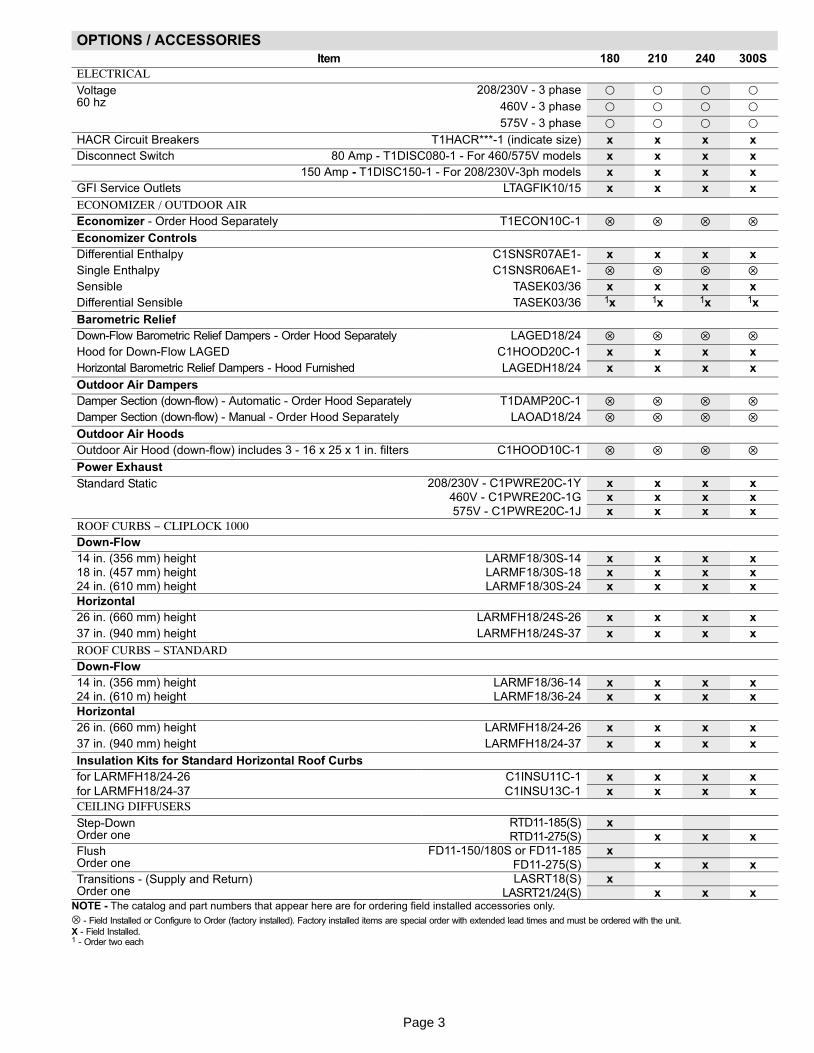
OPTIONS / ACCESSORIES
Item 180 210 240 300S
ELECTRICAL
Voltage60 hz
208/230V − 3 phase � � � �
460V − 3 phase � � � �
575V − 3 phase � � � �
HACR Circuit Breakers T1HACR***−1 (indicate size) x x x x
Disconnect Switch 80 Amp − T1DISC080−1 − For 460/575V models x x x x
150 Amp − T1DISC150−1 − For 208/230V−3ph models x x x x
GFI Service Outlets LTAGFIK10/15 x x x x
ECONOMIZER / OUTDOOR AIREconomizer − Order Hood Separately T1ECON10C−1 � � � �
Economizer Controls
Differential Enthalpy C1SNSR07AE1− x x x x
Single Enthalpy C1SNSR06AE1− � � � �
Sensible TASEK03/36 x x x x
Differential Sensible TASEK03/36 1x 1x 1x 1x
Barometric Relief
Down−Flow Barometric Relief Dampers − Order Hood Separately LAGED18/24 � � � �
Hood for Down−Flow LAGED C1HOOD20C−1 x x x x
Horizontal Barometric Relief Dampers − Hood Furnished LAGEDH18/24 x x x x
Outdoor Air Dampers
Damper Section (down−flow) − Automatic − Order Hood Separately T1DAMP20C−1 � � � �
Damper Section (down−flow) − Manual − Order Hood Separately LAOAD18/24 � � � �
Outdoor Air Hoods
Outdoor Air Hood (down−flow) includes 3 − 16 x 25 x 1 in. filters C1HOOD10C−1 � � � �
Power Exhaust
Standard Static 208/230V − C1PWRE20C−1Y x x x x460V − C1PWRE20C−1G x x x x
575V − C1PWRE20C−1J x x x x
ROOF CURBS − CLIPLOCK 1000Down−Flow
14 in. (356 mm) height LARMF18/30S−14 x x x x18 in. (457 mm) height LARMF18/30S−18 x x x x24 in. (610 mm) height LARMF18/30S−24 x x x x
Horizontal
26 in. (660 mm) height LARMFH18/24S−26 x x x x
37 in. (940 mm) height LARMFH18/24S−37 x x x x
ROOF CURBS − STANDARDDown−Flow
14 in. (356 mm) height LARMF18/36−14 x x x x24 in. (610 m) height LARMF18/36−24 x x x x
Horizontal
26 in. (660 mm) height LARMFH18/24−26 x x x x
37 in. (940 mm) height LARMFH18/24−37 x x x x
Insulation Kits for Standard Horizontal Roof Curbs
for LARMFH18/24−26 C1INSU11C−1 x x x x
for LARMFH18/24−37 C1INSU13C−1 x x x x
CEILING DIFFUSERS
Step−DownOrder one
RTD11−185(S) xRTD11−275(S) x x x
FlushOrder one
FD11−150/180S or FD11−185 x
FD11−275(S) x x x
Transitions − (Supply and Return)Order one
LASRT18(S) xLASRT21/24(S) x x x
NOTE − The catalog and part numbers that appear here are for ordering field installed accessories only.
⊗ − Field Installed or Configure to Order (factory installed). Factory installed items are special order with extended lead times and must be ordered with the unit.
X − Field Installed.1 − Order two each

Page 4
SPECIFICATIONS 15 − 17.5 TONGeneralData
Nominal Tonnage 15 Ton 15 Ton 17.5 Ton 17.5 Ton
Model No. TGA180S2B TGA180H2B TGA210S2B TGA210H2B
Efficiency Type Standard High Standard High
CoolingPerformance
Gross Cooling Capacity − Btuh (kW) 186,000 (54.5) 186,000 (54.5) 218,000 (63.8) 219,000 (64.1)1 Net Cooling Capacity − Btuh (kW) 180,000 (52.7) 180,000 (52.7) 210,000 (61.5) 210,000 (61.5)
ARI Rated Air Flow − cfm (L/s) 6000 (2830) 6000 (2830) 6700 (3160) 7000 (3305)
Total Unit Power − kW 18.6 16.7 22.1 19.41 EER (Btuh/Watt) 9.7 10.8 9.5 10.8
2 Integrated Part Load Value (Btuh/Watt) 10.1 11.2 9.9 11.2
Refrigerant Type R−22 R−22 R−22 R−22
Refrigerant ChargeFurnished
Circuit 1 9 lbs. 0 oz. (4.08 kg) 11 lbs. 8 oz. (5.22kg)
8 lbs. 0 oz. (3.63 kg) 11 lbs. 0 oz. (4.99kg)
Circuit 2 9 lbs. 0 oz. (4.08 kg) 11 lbs. 8 oz. (5.22kg)
8 lbs. 0 oz. (3.63 kg) 11 lbs. 0 oz. (4.99kg)
Circuit 3 9 lbs. 0 oz. (4.08 kg) 11 lbs. 8 oz. (5.22kg)
8 lbs. 0 oz. (3.63 kg) 11 lbs. 0 oz. (4.99kg)
Circuit 4 − − − − − − − − − 11 lbs. 0 oz. (4.99kg)
Gas Heating Options − See Table Below Standard (2 Stage) − Medium (2 Stage) − High (2 Stage)
Compressor Type (no.) Scroll (3) Scroll (3) Scroll (3) Scroll (4)
OutdoorCoils
Net face area − sq. ft. (m2) total 56.0 (5.2) 56.0 (5.2) 56.0 (5.2) 56.0 (5.2)
Tube diameter − in. (mm) 3/8 (9.5) 3/8 (9.5) 3/8 (9.5) 3/8 (9.5)
Number of rows 1 2 1 2
Fins per inch (m) 20 (787) 20 (787) 20 (787) 20 (787)
OutdoorCoil Fans
Motor horsepower (W) (4) 1/3 (249) (4) 1/3 (249) (4) 1/2 (373) (4) 1/3 (249)
Motor rpm 1075 1075 1075 1075
Total Motor watts 1370 1395 1800 1395
Diameter − in. (mm) − No. of blades (4) 24 (610) − 3 (4) 24 (610) − 3 (4) 24 (610) − 3 (4) 24 (610) − 3
Total Air volume − cfm (L/s) 15,850 (7480) 15,450 (7290) 16,000 (7550) 15,450 (7290)
IndoorCoils
Net face area − sq. ft. (m2) total 22.3 (2.07) 22.3 (2.07) 22.3 (2.07) 22.3 (2.07)
Tube diameter − in. (mm) 3/8 (9.5) 3/8 (9.5) 3/8 (9.5) 3/8 (9.5)
No. of rows 3 3 3 4
Fins per inch (m) 14 (551) 14 (551) 14 (551) 14 (551)
Drain connection − number and size (1) 1 in. NPT coupling (1) 1 in. NPT coupling
Expansion device type Balanced Port Thermostatic Expansion Valve, removeable power head3, 4 IndoorBlower andDriveSelection
Nominal motor HP Low Static 3 hp (2.2 kW) 3 hp (2.2 kW) 5 hp (3.7 kW) 5 hp (3.7 kW)
Standard Static 3 hp (2.2 kW) 3 hp (2.2 kW) 5 hp (3.7 kW) 5 hp (3.7 kW)
High Static 5 hp (3.7 kW) 5 hp (3.7 kW) 7.5 hp (5.6 kW) 7.5 hp (5.6 kW)
Max. usable motoroutput (US Only)
Low Static 3.45 hp (2.6 kW) 3.45 hp (2.6 kW) 5.75 hp (4.3 kW) 5.75 hp (4.3 kW)
Standard Static 3.45 hp (2.6 kW) 3.45 hp (2.6 kW) 5.75 hp (4.3 kW) 5.75 hp (4.3 kW)
High Static 5.75 hp (4.3 kW) 5.75 hp (4.3 kW) 8.63 hp (6.4 kW) 8.63 hp (6.4 kW)
Drive Kit Low Static #A − 535−725 rpm #A − 535−725 rpm #2 − 685−865 rpm #2 − 685−865 rpm
Standard Static #1 − 710−965 rpm #1 − 710−965 rpm #3 − 850−1045 rpm #3 − 850−1045 rpm
High Static #4 − 945−1185 rpm #4 − 945−1185 rpm #6 − 1045−1285 rpm #6 − 1045−1285rpm
Field InstalledDrive Kits
Standard toLow Static
#A − 535−725 rpm #A − 535−725 rpm #2 − 685−865 rpm #2 − 685−865 rpm
High to Standard Static #3 − 850−1045 rpm #3 − 850−1045 rpm #7 − 850−1045 rpm #7 − 850−1045 rpm
Blower�wheel�nominal�diameter�x�width (2) 15 x 15 in. (381 x 381 mm)
Filters Type of filter Disposable, pleated MERV 7
No. and size − in. (mm) (6) 24 x 24 x 2 (610 x 610 x 51)
Electrical characteristics 208/230V, 460V or 575V − 60 hertz − 3 phaseNOTE − Net capacity includes evaporator blower motor heat deduction. Gross capacity does not include evaporator blower motor heat deduction.1 Certified in accordance with the ULE certification program, which is based on ARI Standard 340/360; 95�F (35�C) outdoor air temperature and 80�F(27�C) db/67�F
(19�C) wb entering evaporator air; minimum external duct static pressure.2 Integrated Part Load Value tested at 80�F (27�C) outdoor air temperature.3 Using total air volume and system static pressure requirements determine from blower performance tables rpm and motor output required. Maxi-mum usable output of motors furnished are shown. In Canada, nominal motor output is also maximum usable motor output. If motors of comparableoutput are used, be sure to keep within the service factor limitations outlined on the motor nameplate.4 Stocked models are available with standard static drives. High static drives are factory installed (configure to order). Low static drive can be factoryinstalled (configure to order) or standard static drives can be converted to low static with field installed kit. High static models can be converted to stan-dard static with field installed kit.

Page 5
SPECIFICATIONS 20 − 25 TONGeneralData
Nominal Tonnage 20 Ton 20 Ton 25 Ton
Model No. TGA240S2B TGA240H2B TGA300S2B
Efficiency Type Standard High Standard
CoolingPerformance
Gross Cooling Capacity − Btuh (kW) 243,000 (71.2) 251,000 (73.5) 302,000 (88.4)
Net Cooling Capacity − Btuh (kW) 2342,000 (68.5) 240,000 (70.3) 286,000 (83.7)
ARI Rated Air Flow − cfm (L/s) 8000 (3775) 7500 (3540) 9000 (4245)
Total Unit Power − kW 24.1 22.2 30.11 EER (Btuh/Watt) 9.5 10.8 9.5
3 Integrated Part Load Value (Btuh/Watt) 10.1 11.2 9.7
Refrigerant Type R−22 R−22 R−22
Refrigerant ChargeFurnished
Circuit 1 11 lbs. 8 oz. (5.22 kg) 11 lbs. 8 oz. (5.22 kg) 11 lbs. 0 oz. (4.99 kg)
Circuit 2 11 lbs. 8 oz. (5.22 kg) 11 lbs. 8 oz. (5.22 kg) 11 lbs. 0 oz. (4.99 kg)
Circuit 3 11 lbs. 8 oz. (5.22 kg) 11 lbs. 8 oz. (5.22 kg) 11 lbs. 0 oz. (4.99 kg)
Circuit 4 − − − 11 lbs. 8 oz. (5.22 kg) 11 lbs. 0 oz. (4.99 kg)
Gas Heating Options − See Table below Standard (2 Stage) − Medium (2 Stage) − High (2 Stage)
Compressor Type (no.) Scroll (3) Scroll (4) Scroll (4)
OutdoorCoils
Net face area − sq. ft. (m2) total 56.0 (5.2) 56.0 (5.2) 56.0 (5.2)
Tube diameter − in. (mm) 3/8 (9.5) 3/8 (9.5) 3/8 (9.5)
Number of rows 2 2 2
Fins per inch (m) 20 (787) 20 (787) 20 (787)
OutdoorCoil Fans
Motor horsepower (W) (4) 1/3 (249) (4) 1/3 (249) (4) 1/2 (373)
Motor rpm 1075 1075 1075
Total Motor watts 1395 1395 1800
Diameter − in. (mm) − No. of blades (4) 24 (610) − 3 (4) 24 (610) − 3 (4) 24 (610) − 3
Total Air volume − cfm (L/s) 15,450 (7290) 15,450 (7290) 16,000 (7550)
IndoorCoils
Net face area − sq. ft. (m2) total 22.3 (2.07) 22.3 (2.07) 22.3 (2.07)
Tube diameter − in. (mm) 3/8 (9.5) 3/8 (9.5) 3/8 (9.5)
No. of rows 3 4 4
Fins per inch (m) 14 (551) 14 (551) 14 (551)
Drain connection − no. and size (1) 1 in. NPT coupling (1) 1 in. NPT coupling (1) 1 in. NPT coupling
Expansion device type Balanced Port Thermostatic Expansion Valve, removeable power head4, 5 IndoorBlower andDriveSelection
Nominal motor HP Low Static 5 hp (3.7 kW) 5 hp (3.7 kW) 7.5 hp (5.6 kW)
Standard Static 7.5 hp (5.6 kW) 7.5 hp (5.6 kW) 10 hp (7.5 kW)
High Static 10 hp (7.5 kW) 10 hp (7.5 kW) N/A
Max. usable motoroutput (US Only)
Low Static 5.75 hp (4.3 kW) 5.75 hp (4.3 kW) 8.63 hp (6.4 kW)
Standard Static 8.63 hp (6.4 kW) 8.63 hp (6.4 kW) 11.5 hp (8.6 kW)
High Static 11.5 hp (8.6 kW) 11.5 hp (8.6 kW) N/A
Drive Kit Low Static #2 − 685− 865 rpm #2 − 685−865 rpm #7 − 850−1045 rpm
Standard Static #7 − 850−1045 rpm #7 − 850−1045 rpm #6 − 1045−1285 rpm
High Static #6 − 1045−1285 rpm #6 − 1045−1285 rpm N/A
Field Installed Low Static Drive Kit #9 − 685−865 rpm #9 − 685−865 rpm #7 − 850−1045 rpm
Blower�wheel�nominal�diameter�x�width (2) 15 x 15 in. (381 x 381 mm)
Filters Type of filter Disposable, pleated MERV 7
No. and size − in. (mm) (6) 24 x 24 x 2 (610 x 610 x 51)
Electrical characteristics 208/230V, 460V or 575V − 60 hertz − 3 phase
NOTE − Net capacity includes evaporator blower motor heat deduction. Gross capacity does not include evaporator blower motor heat deduction.1 Certified in accordance with the ULE certification program, which is based on ARI Standard 340/360; 95�F (35�C) outdoor air temperature and 80�F(27�C) db/67�F (19�C) wb entering evaporator air; minimum external duct static pressure.2 Tested at conditions included in with ARI Standard 340/360; 95�F (35�C) outdoor air temperature and 80�F (27�C) db/67�F (19�C) wb enteringevaporator air; minimum external duct static pressure.3 Integrated Part Load Value tested at 80�F (27�C) outdoor air temperature.4 Using total air volume and system static pressure requirements determine from blower performance tables rpm and motor output required. Maxi-mum usable output of motors furnished are shown. In Canada, nominal motor output is also maximum usable motor output. If motors of comparableoutput are used, be sure to keep within the service factor limitations outlined on the motor nameplate.5 Stocked models are available with standard static drives. High static drives are factory installed (configure to order). Low static drive can be factory installed(configure to order) or standard static drives can be converted to low static with field installed kit.

Page 6
SPECIFICATIONS − GAS HEAT 15 − 17.5 tonUsage Data Model No. TGA180S2B, TGA180H2B, TGA210S2B, or TGA210H2B
Gas HeatingPerformance
Heat Input Type Standard (2Stage)
Medium (2Stage)
High (2 Stage)
Input − Btuh (KW) First Stage 169,000 (49.5) 234,000 (68.6) 312,000 (91.4)
Second Stage 260,000 (76.2) 360,000 (105.5) 480,000 (140.6)
Output − Btuh (kW) Second Stage 208,000 (60.9) 288,000 (84.4) 384,000 (112.5)
CSA Thermal Efficiency 80.0%
Gas Supply Connections 1 in. NPT
Recommended Gas Supply Pressure − Natural / LPG/Propane 7 in. w.g. (1.7 kPa) / 10.8 in. w.g. (2.7 kPa)
SPECIFICATIONS − GAS HEAT 20 − 25 tonUsage Data Model No. TGA240S2B, TGA240H2B, or TGA300S2B
Gas HeatingPerformance
Heat Input Type Standard (2Stage)
Medium (2Stage)
High (2 Stage)
Input − Btuh (KW) First Stage 169,000 (49.5) 234,000 (68.6) 312,000 (91.4)
Second Stage 260,000 (76.2) 360,000 (105.5) 480,000 (140.6)
Output − Btuh (kW) Second Stage 208,000 (60.9) 288,000 (84.4) 384,000 (112.5)
CSA Thermal Efficiency 80.0%
Gas Supply Connections 1 in. NPT
Recommended Gas Supply Pressure − Natural / LPG/Propane 7 in. w.g. (1.7 kPa) / 11 in. w.g. (2.7 kPa)
HIGH ALTITUDE DERATE
Units may be installed at altitudes up to 2000 feet (610 m) above sea level without anymodification. At altitudes above 2000 feet (610 m), units must be derated to match gasmanifold pressures shown in table below. NOTE − This is the only permissible derate forthese units.
Altitude − ft. (m)Natural Gas LPG/Propane
in. w.g. kPa in. w.g. kPa
2001 − 3000 (610 − 915) 3.6 0.90 10.2 2.54
3001 − 4000 (915 − 1220) 3.5 0.87 9.9 2.46
4001 − 5000 (1220 − 1525) 3.4 0.85 9.6 2.39
5001 − 6000 (1525 − 1830) 3.3 0.82 9.4 2.34
6001 − 7000 (1830 − 2135) 3.2 0.80 9.1 2.26
7001 − 8000 (2135 − 2440) 3.1 0.77 8.8 2.19
8001 − 10,000 (2440 − 3048) Contact Technical Support

Page 7
BLOWER DATA 15 TON
BLOWER TABLE INCLUDES RESISTANCE FOR BASE UNIT WITH STANDARD GAS HEAT, WET INDOOR COIL & AIR FIL-TERS IN PLACE.FOR ALL UNITS ADD:
1 − Any factory installed options air resistance (high gas heat, economizer, etc.). See table below2 − Any field installed accessories air resistance (duct resistance, diffuser, etc.). See page 18
Then determine from table the blower motor output and drive required.
0.30 to 1.40 in. w.g. TGA180Air
Volumecfm
External Static (in. w.g.)
0.30 0.40 0.50 0.60 0.70 0.80 0.90 1.00 1.10 1.20 1.30 1.40
RPM BHP RPM BHP RPM BHP RPM BHP RPM BHP RPM BHP RPM BHP RPM BHP RPM BHP RPM BHP RPM BHP RPM BHP
Low Static − 3 HP, Drive Kit A Standard Static − 3 HP, Drive Kit 1
4800 577 1.13 620 1.31 662 1.48 702 1.66 742 1.83 777 2.01 811 2.18 842 2.36 872 2.54 902 2.72 932 2.89 960 3.07
5000 585 1.25 628 1.43 670 1.60 710 1.78 750 1.95 783 2.13 815 2.30 848 2.50 880 2.70 910 2.88 940 3.05 968 3.23
5500 605 1.45 648 1.65 690 1.85 728 2.05 765 2.25 800 2.45 835 2.65 865 2.85 895 3.05 925 3.25 955 3.45 983 3.65
6000 630 1.75 670 1.95 710 2.15 748 2.38 785 2.60 818 2.83 850 3.05 880 3.25 910 3.45 940 3.68 970 3.90 998 4.13
6500 650 2.05 690 2.28 730 2.50 768 2.75 805 3.00 838 3.23 870 3.45 900 3.70 930 3.95 958 4.18 985 4.40 1013 4.63
7000 675 2.35 715 2.63 755 2.90 790 3.15 825 3.40 858 3.68 890 3.95 920 4.20 950 4.45 978 4.70 1005 4.95 1030 5.18
7200 687 2.55 725 2.81 763 3.06 798 3.33 833 3.60 866 3.86 898 4.11 926 4.36 954 4.61 984 4.90 1013 5.19 1038 5.44
NOTE − Bold − To operate in this range, unit must be ordered with High Static Drive and drive kit #3 must be ordered separately for field installation.
1.50 to 2.50 in. w.g. TGA180Air
Volumecfm
External Static (in. w.g.)
1.50 1.60 1.70 1.80 1.90 2.00 2.10 2.20 2.30 2.40 2.50
RPM BHP RPM BHP RPM BHP RPM BHP RPM BHP RPM BHP RPM BHP RPM BHP RPM BHP RPM BHP RPM BHP
High Static − 5 HP, Drive Kit 4 Field Furnished Drive
4800 987 3.24 1014 3.42 1041 3.60 1064 3.78 1087 3.95 1112 4.13 1136 4.30 1159 4.50 1181 4.70 1204 4.88 1226 5.06
5000 995 3.40 1020 3.60 1045 3.80 1070 3.98 1095 4.15 1118 4.33 1140 4.50 1163 4.70 1185 4.90 1208 5.10 1230 5.30
5500 1010 3.85 1035 4.05 1060 4.25 1085 4.48 1110 4.70 1133 4.90 1155 5.10 1178 5.30 1200 5.50 1220 5.70 1240 5.90
6000 1025 4.35 1050 4.58 1075 4.80 1098 5.00 1120 5.20 1145 5.43 1170 5.65 1193 5.88 1215 6.10 1235 6.33 1255 6.55
6500 1040 4.85 1065 5.10 1090 5.35 1115 5.60 1140 5.85 1163 6.08 1185 6.30 1205 6.53 1225 6.75 1248 7.00 1270 7.25
7000 1055 5.40 1080 5.68 1105 5.95 1130 6.20 1155 6.45 1178 6.70 1200 6.95 1220 7.20 1240 7.45 1263 7.73 1285 8.00
7200 1063 5.68 1088 5.94 1113 6.19 1136 6.44 1159 6.69 1182 6.96 1204 7.23 1226 7.50 1248 7.77 1269 8.03 1289 8.28
NOTE − Bold, italics − drive is capable of the values noted but will exceed motor horsepower.
AIR RESISTANCE (in. w.g.) − Factory Installed Options
Air Volume − cfmGas Heat Exchanger
EconomizerHorizontalRoof Curb
MERV 11FilterMed. Heat High Heat
4800 .08 .10 − − − .08 .01
5000 .09 .11 − − − .08 .01
5500 .10 .13 − − − .10 .02
6000 .12 .15 − − − .11 .02
6500 .13 .17 .02 .13 .02
7000 .15 .19 .04 .15 .03
7200 .16 .20 .05 .16 .03

Page 8
BLOWER DATA 17.5 TON
BLOWER TABLE INCLUDES RESISTANCE FOR BASE UNIT WITH STANDARD GAS HEAT, WET INDOOR COIL & AIR FIL-TERS IN PLACE.FOR ALL UNITS ADD:
1 − Any factory installed options air resistance (high gas heat, economizer, etc.). See table below2 − Any field installed accessories air resistance (duct resistance, diffuser, etc.). See page 18
Then determine from table the blower motor output and drive required.
0.20 to 1.20 in. w.g. TGA210Air
Volumecfm
External Static (in. w.g.)
0.20 0.30 0.40 0.50 0.60 0.70 0.80 0.90 1.00 1.10 1.20
RPM BHP RPM BHP RPM BHP RPM BHP RPM BHP RPM BHP RPM BHP RPM BHP RPM BHP RPM BHP RPM BHP
Field Furnished Low Static − 5 HP, Drive Kit 2 Standard Static − 5 HP, Drive Kit 3
5600 609 1.51 652 1.71 694 1.91 732 2.12 769 2.33 803 2.53 837 2.73 868 2.93 899 3.13 928 3.33 957 3.53
6000 630 1.75 670 1.95 710 2.15 748 2.38 785 2.60 818 2.83 850 3.05 880 3.25 910 3.45 940 3.68 970 3.90
6500 650 2.05 690 2.28 730 2.50 768 2.75 805 3.00 838 3.23 870 3.45 900 3.70 930 3.95 958 4.18 985 4.40
7000 675 2.35 715 2.63 755 2.90 790 3.15 825 3.40 858 3.68 890 3.95 920 4.20 950 4.45 978 4.70 1005 4.95
7500 700 2.75 738 3.03 775 3.30 810 3.58 845 3.85 878 4.15 910 4.45 938 4.70 965 4.95 993 5.23 1020 5.50
8000 725 3.20 763 3.50 800 3.80 833 4.08 865 4.35 898 4.65 930 4.95 958 5.23 985 5.50 1013 5.80 1040 6.10
8400 746 3.55 783 3.87 819 4.18 853 4.49 886 4.80 916 5.12 946 5.43 974 5.73 1001 6.03 1029 6.35 1056 6.66
NOTE − Bold − To operate in this range, unit must be ordered with High Static Drive and drive kit #7 must be ordered separately for field installation.
1.30 to 2.40 in. w.g. TGA210Air
Volumecfm
External Static (in. w.g.)
1.30 1.40 1.50 1.60 1.70 1.80 1.90 2.00 2.10 2.20 2.30 2.40
RPM BHP RPM BHP RPM BHP RPM BHP RPM BHP RPM BHP RPM BHP RPM BHP RPM BHP RPM BHP RPM BHP RPM BHP
Standard Static − 5 HP, Drive Kit 3 High Static − 7.5 HP, Drive Kit 6
5600 985 3.74 1012 3.95 1037 4.15 1062 4.35 1087 4.58 1112 4.80 1135 5.00 1157 5.20 1180 5.41 1202 5.62 1223 5.83 1244 6.04
6000 998 4.13 1025 4.35 1050 4.58 1075 4.80 1098 5.00 1120 5.20 1145 5.43 1170 5.65 1193 5.88 1215 6.10 1235 6.33 1255 6.55
6500 1013 4.63 1040 4.85 1065 5.10 1090 5.35 1115 5.60 1140 5.85 1163 6.08 1185 6.30 1205 6.53 1225 6.75 1248 7.00 1270 7.25
7000 1030 5.18 1055 5.40 1080 5.68 1105 5.95 1130 6.20 1155 6.45 1178 6.70 1200 6.95 1220 7.20 1240 7.45 1263 7.73 1285 8.00
7500 1048 5.78 1075 6.05 1100 6.33 1125 6.60 1148 6.88 1170 7.15 1193 7.40 1215 7.65 1238 7.95 1260 8.25 1280 8.50 1300 8.75
8000 1065 6.40 1090 6.70 1115 6.98 1140 7.25 1163 7.55 1185 7.85 1208 8.13 1230 8.40 1253 8.70 1275 9.00 1295 9.30 1315 9.60
8400 1081 6.96 1106 7.26 1131 7.58 1156 7.89 1179 8.19 1201 8.49 1224 8.79 1246 9.09 1266 9.38 1286 9.67 1307 9.98 1328 10.29
NOTE − Bold, italics − drive is capable of the values noted but will exceed motor horsepower.Italics − field furnished drive
AIR RESISTANCE (in. w.g.) − Factory Installed Options
Air Volume − cfmGas Heat Exchanger
EconomizerHorizontalRoof Curb
MERV 11FilterMed. Heat High Heat
5600 .10 .13 − − − .10 .02
6000 .12 .15 − − − .11 .02
6500 .13 .17 .02 .13 .02
7000 .15 .19 .04 .15 .03
7500 .17 .21 .06 .17 .03
8000 .19 .24 .09 .19 .04
8400 .20 .26 .11 .21 .04

Page 9
BLOWER DATA 20 TON
BLOWER TABLE INCLUDES RESISTANCE FOR BASE UNIT WITH STANDARD GAS HEAT, WET INDOOR COIL & AIR FIL-TERS IN PLACE.FOR ALL UNITS ADD:
1 − Any factory installed options air resistance (high gas heat, economizer, etc.). See table below2 − Any field installed accessories air resistance (duct resistance, diffuser, etc.). See page 18
Then determine from table the blower motor output and drive required.
0.20 to 1.10 in. w.g. TGA240Air
Volumecfm
External Static (in. w.g.)
.20 0.30 0.40 0.50 0.60 0.70 0.80 0.90 1.00 1.10 1.20
RPM BHP RPM BHP RPM BHP RPM BHP RPM BHP RPM BHP RPM BHP RPM BHP RPM BHP RPM BHP RPM BHP
Low Static − 5 HP, Drive Kit 2 Standard Static − 7.5 HP, Drive Kit 7
6400 648 1.99 688 2.22 727 2.46 764 2.69 801 2.92 834 3.15 866 3.39 896 3.62 926 3.85 954 4.08 981 4.30
7000 675 2.35 715 2.63 755 2.90 790 3.15 825 3.40 858 3.68 890 3.95 920 4.20 950 4.45 978 4.70 1005 4.95
7500 700 2.75 738 3.03 775 3.30 810 3.58 845 3.85 878 4.15 910 4.45 938 4.70 965 4.95 993 5.23 1020 5.50
8000 725 3.20 763 3.50 800 3.80 833 4.08 865 4.35 898 4.65 930 4.95 958 5.23 985 5.50 1013 5.80 1040 6.10
8500 750 3.65 788 3.98 825 4.30 858 4.60 890 4.90 920 5.23 950 5.55 978 5.85 1005 6.15 1033 6.48 1060 6.80
9000 780 4.20 815 4.53 850 4.85 880 5.18 910 5.50 940 5.83 970 6.15 998 6.48 1025 6.80 1053 7.15 1080 7.50
9600 811 4.87 845 5.22 879 5.57 910 5.94 941 6.31 970 6.67 999 7.02 1027 7.38 1054 7.74 1079 8.08 1104 8.41
1.30 to 2.40 in. w.g. TGA240Air
Volumecfm
External Static (in. w.g.)
1.30 1.40 1.50 1.60 1.70 1.80 1.90 2.00 2.10 2.20 2.30 2.40
RPM BHP RPM BHP RPM BHP RPM BHP RPM BHP RPM BHP RPM BHP RPM BHP RPM BHP RPM BHP RPM BHP RPM BHP
Standard Static High Static − 10 HP, Drive Kit 6
6400 1008 4.53 1035 4.75 1060 4.98 1085 5.22 1110 5.45 1135 5.68 1157 5.91 1180 6.15 1202 6.40 1225 6.65 1246 6.88 1268 7.11
7000 1030 5.18 1055 5.40 1080 5.68 1105 5.95 1130 6.20 1155 6.45 1178 6.70 1200 6.95 1220 7.20 1240 7.45 1263 7.73 1285 8.00
7500 1048 5.78 1075 6.05 1100 6.33 1125 6.60 1148 6.88 1170 7.15 1193 7.40 1215 7.65 1238 7.95 1260 8.25 1280 8.50 1300 8.75
8000 1065 6.40 1090 6.70 1115 6.98 1140 7.25 1163 7.55 1185 7.85 1208 8.13 1230 8.40 1253 8.70 1275 9.00 1295 9.30 1315 9.60
8500 1085 7.10 1110 7.40 1135 7.73 1160 8.05 1183 8.35 1205 8.65 1228 8.95 1250 9.25 1270 9.55 1290 9.85 1310 10.15 1330 10.45
9000 1105 7.83 1130 8.15 1153 8.45 1175 8.75 1198 9.08 1220 9.40 1243 9.75 1265 10.10 1288 10.45 1310 10.80 1330 11.10 1350 11.40
9600 1129 8.77 1154 9.13 1177 9.46 1199 9.78 1222 10.14 1244 10.50 1267 10.87 1289 11.23 − − − − − − − − − − − −
NOTE − italics − field furnished drive.
AIR RESISTANCE (in. w.g.) − Factory Installed Options
Air Volume − cfmGas Heat Exchanger
EconomizerHorizontalRoof Curb
MERV 11FilterMed. Heat High Heat
6400 .13 .17 .02 .13 .02
7000 .15 .19 .04 .15 .03
7500 .17 .21 .06 .17 .03
8000 .19 .24 .09 .19 .04
8500 .20 .26 .11 .21 .04
9000 .23 .29 .14 .24 .04
9600 .25 .32 .16 .26 .05

Page 10
BLOWER DATA STANDARD 25 TON
BLOWER TABLE INCLUDES RESISTANCE FOR BASE UNIT WITH STANDARD GAS HEAT, WET INDOOR COIL & AIR FIL-TERS IN PLACE.FOR ALL UNITS ADD:
1 − Any factory installed options air resistance (high gas heat, economizer, etc.). See table below2 − Any field installed accessories air resistance (duct resistance, diffuser, etc.). See page 18
Then determine from table the blower motor output and drive required.
0.00 to 1.00 in. w.g. TGA300S
AirVolume
cfm
External Static (in. w.g.)
0.00 0.10 0.20 0.30 0.40 0.50 0.60 0.70 0.80 0.90 1.00
RPM BHP RPM BHP RPM BHP RPM BHP RPM BHP RPM BHP RPM BHP RPM BHP RPM BHP RPM BHP RPM BHP
Low Static − 7.5 HP, Drive Kit 7
8000 725 3.20 763 3.50 800 3.80 833 4.08 865 4.35 898 4.65 930 4.95 958 5.23 985 5.50 1013 5.80 1040 6.10
8500 750 3.65 788 3.98 825 4.30 858 4.60 890 4.90 920 5.23 950 5.55 978 5.85 1005 6.15 1033 6.48 1060 6.80
9250 790 4.45 825 4.80 860 5.15 893 5.50 925 5.85 955 6.20 985 6.55 1013 6.88 1040 7.20 1065 7.53 1090 7.85
10000 835 5.40 868 5.78 900 6.15 930 6.50 960 6.85 988 7.23 1015 7.60 1043 7.98 1070 8.35 1095 8.70 1120 9.05
10750 875 6.40 908 6.83 940 7.25 970 7.65 1000 8.05 1028 8.45 1055 8.85 1080 9.25 1105 9.65 1130 10.05 1155 10.45
11500 915 7.40 948 7.88 980 8.35 1010 8.80 1040 9.25 1068 9.68 1095 10.10 1118 10.53 1140 10.95 1165 11.40 1190 11.85
NOTE − Bold, italics − drive is capable of the values noted but will exceed motor horsepower.
1.10 to 2.20 in. w.g. TGA300S
AirVolume
cfm
External Static (in. w.g.)
1.10 1.20 1.30 1.40 1.50 1.60 1.70 1.80 1.90 2.00 2.10 2.20
RPM BHP RPM BHP RPM BHP RPM BHP RPM BHP RPM BHP RPM BHP RPM BHP RPM BHP RPM BHP RPM BHP RPM BHP
Standard Static − 10 HP, Drive Kit 6 Field Furnished Drive
8000 1065 6.40 1090 6.70 1115 6.98 1140 7.25 1163 7.55 1185 7.85 1208 8.13 1230 8.40 1253 8.70 1275 9.00 1295 9.30 1315 9.60
8500 1085 7.10 1110 7.40 1135 7.73 1160 8.05 1183 8.35 1205 8.65 1228 8.95 1250 9.25 1270 9.55 1290 9.85 1310 10.15 1330 10.45
9250 1115 8.20 1140 8.55 1163 8.88 1185 9.20 1208 9.53 1230 9.85 1253 10.20 1275 10.55 1295 10.88 1315 11.20 − − − − − − − − − − − −
10000 1145 9.43 1170 9.80 1193 10.15 1215 10.50 1238 10.88 1260 11.25 1283 11.62 − − − − − − − − − − − − − − − − − − − − − − − − − − − − − −
10750 1178 10.83 1200 11.20 1222 11.57 − − − − − − − − − − − − − − − − − − − − − − − − − − − − − − − − − − − − − − − − − − − − − − − − − − − − − −
11500 1210 12.23 1230 12.60 − − − − − − − − − − − − − − − − − − − − − − − − − − − − − − − − − − − − − − − − − − − − − − − − − − − − − − − − − − − −
NOTE − Bold, italics − drive is capable of the values noted but will exceed motor horsepower.
AIR RESISTANCE (in. w.g.) − Factory Installed Options
Air Volume − cfmGas Heat Exchanger
EconomizerHorizontalRoof Curb
MERV 11FilterMed. Heat High Heat
8000 .19 .24 .09 .13 .04
8500 .20 .26 .11 .15 .04
9250 .24 .30 .15 .18 .05
10,000 .27 .35 .19 .21 .06
Page 11
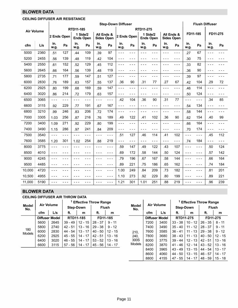
BLOWER DATA
CEILING DIFFUSER AIR RESISTANCE
Air Volume
Step-Down Diffuser Flush Diffuser
RTD11−185 RTD11−275
FD11−185 FD11−2752 Ends Open
1 Side/2Ends Open
All Ends &Sides Open 2 Ends Open
1 Side/2Ends Open
All Ends &Sides Open
cfm L/sin.
w.g.Pa
in.w.g.
Pain.
w.g.Pa
in.w.g.
Pain.
w.g.Pa
in.w.g.
Pain.
w.g.Pa
in.w.g.
Pa
5000 2360 .51 127 .44 109 .39 97 − − − − − − − − − − − − − − − − − − .27 67 − − − − − −
5200 2455 .56 139 .48 119 .42 104 − − − − − − − − − − − − − − − − − − .30 75 − − − − − −
5400 2550 .61 152 .52 129 .45 112 − − − − − − − − − − − − − − − − − − .33 82 − − − − − −
5600 2645 .66 164 .56 139 .48 119 − − − − − − − − − − − − − − − − − − .36 90 − − − − − −
5800 2735 .71 177 .59 147 .51 127 − − − − − − − − − − − − − − − − − − .39 97 − − − − − −
6000 2830 .76 189 .63 157 .55 137 .36 90 .31 77 .27 67 .42 104 .29 72
6200 2925 .80 199 .68 169 .59 147 − − − − − − − − − − − − − − − − − − .46 114 − − − − − −
6400 3020 .86 214 .72 179 .63 157 − − − − − − − − − − − − − − − − − − .50 124 − − − − − −
6500 3065 − − − − − − − − − − − − − − − − − − .42 104 .36 90 .31 77 − − − − − − .34 85
6600 3115 .92 229 .77 191 .67 167 − − − − − − − − − − − − − − − − − − .54 134 − − − − − −
6800 3210 .99 246 .83 206 .72 174 − − − − − − − − − − − − − − − − − − .58 144 − − − − − −
7000 3305 1.03 256 .87 216 .76 189 .49 122 .41 102 .36 90 .62 154 .40 99
7200 3400 1.09 271 .92 229 .80 199 − − − − − − − − − − − − − − − − − − .66 164 − − − − − −
7400 3490 1.15 286 .97 241 .84 209 − − − − − − − − − − − − − − − − − − .70 174 − − − − − −
7500 3540 − − − − − − − − − − − − − − − − − − .51 127 .46 114 .41 102 − − − − − − .45 112
7600 3585 1.20 301 1.02 254 .88 219 − − − − − − − − − − − − − − − − − − .74 184 − − − − − −
8000 3775 − − − − − − − − − − − − − − − − − − .59 147 .49 122 .43 107 − − − − − − .50 124
8500 4010 − − − − − − − − − − − − − − − − − − .69 172 .58 144 .50 124 − − − − − − .57 142
9000 4245 − − − − − − − − − − − − − − − − − − .79 196 .67 167 .58 144 − − − − − − .66 164
9500 4485 − − − − − − − − − − − − − − − − − − .89 221 .75 186 .65 162 − − − − − − .74 184
10,000 4720 − − − − − − − − − − − − − − − − − − 1.00 249 .84 209 .73 182 − − − − − − .81 201
10,500 4955 − − − − − − − − − − − − − − − − − − 1.10 273 .92 229 .80 199 − − − − − − .89 221
11,000 5190 − − − − − − − − − − − − − − − − − − 1.21 301 1.01 251 .88 219 − − − − − − .96 239
BLOWER DATA
CEILING DIFFUSER AIR THROW DATA
ModelNo.
Air Volume1 Effective Throw Range
Step-Down Flush
cfm L/s ft. m ft. m
180Models
Diffuser Model RTD11−185 FD11−185
5600 2645 39 − 49 12 − 15 28 − 37 9 − 11
5800 2740 42 − 51 13 − 16 29 − 38 9 − 12
6000 2830 44 − 54 13 − 17 40 − 50 12 − 15
6200 2925 45 − 55 14 − 17 42 − 51 13 − 16
6400 3020 46 − 55 14 − 17 53 − 52 13 − 16
6600 3115 57 − 56 14 − 17 45 − 56 14 − 17
ModelNo.
Air Volume1 Effective Throw Range
Step-Down Flush
cfm L/s ft. m ft. m
210, 240, 300S
Models
Diffuser Model RTD11−275 FD11−275
7200 3400 33 − 38 10 − 12 26 − 35 8 − 11
7400 3490 35 − 40 11 − 12 28 − 37 9 − 11
7600 3585 36 − 41 11 − 13 29 − 38 9 − 12
7800 3680 38 − 43 11 − 13 40 − 50 12 − 15
8000 3775 39 − 44 12 − 13 42 − 51 13 − 16
8200 3870 41 − 46 12 − 14 43 − 52 13 − 16
8400 3965 43 − 49 13 − 15 44 − 54 13 − 17
8600 4060 44 − 50 13 − 15 46 − 57 14 − 17
8800 4155 47 − 55 14 − 17 48 − 59 15 − 18

Page 12
DRIVE KIT SPECIFICATIONS
Blower Motor Outputs RPM Range
Nominal hpMaxi-
mum hpNominal
kWMaxi-
mum kWDrive A Drive 1 Drive 2 Drive 3 Drive 4 Drive 6 Drive 7 Drive 9
3 3.45 2.2 2.6 535−725 710−965 − − − − − − − − − − − − − − − − − − − − − − − −
5 5.75 3.7 4.3 − − − − − − − − 685−865 850−1045 945−1185 − − − − − − − − − − − −
7.5 8.63 5.6 6.4 − − − − − − − − − − − − − − − − − − − − 1045−1285 850−1045 685−865
10 11.5 7.5 8.6 − − − − − − − − − − − − − − − − − − − − 1045−1285 − − − − − − − −
*Using total air volume and system static pressure requirements determine from blower performance tables rpm and motor output required. Maximum usable output of motorsfurnished by manufacturer are shown. In Canada, nominal motor output is also maximum usable motor output. If motors of comparable output are used, be sure to keep withinthe service factor limitations outlined on the motor nameplate.
MANUFACTURER’S NUMBERS
DriveNo.
H.P.
DRIVE COMPONENTS
RPM ADJUSTABLE SHEAVE FIXED SHEAVE BELTS SPLIT BUSHING
Min Max Supplier No. OEMPart No.
Supplier No. OEM Part No. SupplierNo.
OEMPart No.
Supplier No. OEMPart No.
A 2 & 3 535 725 1VP40x7/8 79J0301 BK95 x 1−7/16 80K1601 BX59 59A5001 N/A N/A
1 3 710 965 1VP40x7/8 79J0301 BK72 x 1-7/16 100244−13 BX56 100245−11 N/A N/A
2 3 & 5High
685 865 1VP50x1−1/8 P−8−1977 BK100 x 1-7/16 39L1301 BX62 57A7701 N/A N/A
3 5 850 1045 1VP65x1−1/8 100239−03 BK110H 100788−06 BX66 97J5901 H−1−7/16 49M6201
4 5 945 1185 1VP60x1−1/8 41C1301 BK90H x 1−7/16 100788−04 BX62 57A7701 H−1−7/16 49M6201
5 7.5 945 1185 1VP60x1−3/8 78L5501 BK90H x 1−7/16 100788−04 BX63 97J5501 H−1−7/16 49M6201
6 7.5 1045 1285 1VP65x1−3/8 78M7101 BK90H x 1−7/16 100788−04 BX64 97J5801 H−1−7/16 49M6201
6 10 1045 1285 1VP65x1−3/8 78M7101 1B5V86 78M8301 5VX760 100245−21 B−1−7/16 100246−01
7 7.5 850 1045 1VP65x1−3/8 78M7101 BK110H 100788−06 BX66 97J5901 H−1−7/16 49M6201
8 10 1135 1365 1VP65x1−3/8 78M7101 1B5V80 100240−05 5VX660 100245−20 B−1−7/16 100246−01

Page 13
FIGURE 1
TGA PARTS ARRANGEMENT INDOOR COIL
BLOWERMOTOR
OUTDOORFANS
OUTDOORCOILCONDENSATE
DRAIN
FILTERS(SIX − 24 X 24 X 2")
ECONOMIZERDAMPERS
(OPTIONAL)
COMPRESSORS −4TH COMPRESSORON 210H, 240H, &300S UNITS ONLY
BLOWERS
MCC (A45)CONTROL
COMBUSTIONAIR INDUCER
BURNERSGAS VALVE
HEATEXCHANGER
TUBES
FILTERDRIERS
FIGURE 2
TGA CONTROL BOX
T1 K10
K3 K1 K2
C1C2
A3
K14 K146
A12
K68
T18 T3/F10 T13/F6
C2
C19 C18
K65
K138TB1
GND
S42
A45MCC
TB2
F10 SHOWN T13 SHOWN

Page 14
I−UNIT COMPONENTS
TGA unit components are shown in figure1. All units come
standard with removeable unit panels. All L1, L2, and L3 wir-
ing is color coded; L1 is red, L2 is yellow, and L3 is blue.
A−Control Box Components
TGA control box components are shown in figure 2. The
control box is located in the compressor compartment.
1−Disconnect Switch S48 (field installed)
All units may be equipped with an optional disconnect switch
S48, or circuit breaker, CB10. S48 and CB10 can be a toggle
switch or a twist style switch. Both types can be used by the
service technician to disconnect power to the unit. CB10
when use, will be in the same location as S48 on the wiring
diagram.
2−Terminal Strip TB2All units are equipped with TB2. Units without S48 or CB10
will have incoming power connected to TB2.
3−Control Transformer T1 (all units)
All use a single line voltage to 24VAC transformer
mounted in the control box. Transformer supplies power
to control circuits in the unit. The transformer is rated at
70VA and is protected by a 3.5 amp circuit breaker (CB8)
which is located on the transformer itself. The 208/230
(Y) voltage transform-
ers have two primary
voltage taps, but only
one may be used de-
pending on supply volt-
age. See figure 3. 460
(G) and 575 (J) voltage
transformers use a
single primary voltage
tap.
4−C. A. I. Transformers T3 & T13 575V OnlyAll TGA 575 (J) voltage units use transformers T3 and T13
mounted in the control box. The transformers have an output
rating of 0.5A. T3 transformer supplies 230 VAC power to com-
bustion air inducer motor B6 and T13 supplies 230 VAC to
combustion air inducer motor B15.
5−Contactor Transformer T18
T18 is a single line voltage to 24VAC transformer used in
4 compressor units only. Transformer T18 is protected
by a 3.5 amp circuit breaker (CB18) located on the transformer
itself. T18 is identical to transformer T1. The transformer
supplies 24VAC power to the contactors.
6−Terminal Strip TB1All indoor thermostat connections will be to TB1 located on
MCC board A45. For thermostats with �occupied � and �un-
occupied" modes, a factory installed jumper across termi-
nals A1 and A2 should be removed. Unit wiring is designed
for a three−stage thermostat. For two−stage applications
jumper between Y2 and Y3 on TB1.
7−Terminal Strip TB14Terminal strip TB14 located on the MCC board A45 distrib-
utes 24V power from transformer T1 to the control box com-
ponents. Units not equipped with smoke detectors A17 or
A64, will have a factory installed jumper across terminals
24VAC and R.
8−Outdoor Fan Capacitors C1, C2, C18 & C19
Fan capacitors C1, C2, C18, C19 are 10 MFD / 370V capac-
itors used to assist in the start up of condenser fans B4, B5,
B21, B22 respectively.
9−Outdoor Fan Relay K10 & K68
Outdoor fan relays K10 and K68 used in all units, are DPDT
relays with a 24VAC coil. In all TGA units K10 energizes con-
denser fans B4 and B5 and K68 energizes condenser fans
B21 and B22.
10−Fuses F10 and F6
Two line voltage fuses F10 provide overcurrent protection
to all condenser fans in all Y voltage TGA units and rated at
30A. Fuses F6 provide overcurrent protection for optional
field installed power exhaust fans and rated at 15A.
11−Compressor Contactor K1, K2 & K14 (allunits)K146 (TGA 210H, 240H, 300S units only)
All compressor contactors are three-pole-double-break
contactors with 24VAC coils. In all TGA180, 210S and 240S
units, K1, K2 and K14 energize compressors B1, B2 and
B13 in response to thermostat demand. In the TGA210H,
240H and 300S units, K1, K2, K14 and K146 energize
compressors B1, B2, B13 and B20 in response to ther-
mostat demand.
12−Blower Contactor K3
Blower contactor K3, used in all units, is a three-pole-double-
break contactor with a 24VAC coil used to energize the indoor
blower motor B3 in response to blower demand. K3 is ener-
gized by relay KD on the A45 MCC board.
FIGURE 3
BLUE YELLOW
ORANGE
RED
BLACK
230 VOLTS
208 VOLTS
PRIMARY
SECONDARY
208/230V TRANSFORMER

Page 15
13−Blower Motor Overload Relay S42S42 is a manual reset overload relay, used in all TGA units
equipped with 10 or more HP standard efficiency motors.
The relay is connected in line with the blower motor to moni-
tor the current flow to the motor. When the relay senses an
overload condition, a set of normally closed contacts opens
de−energizing the 24 volt output of T1. See figure figure 4.
14−Power Exhaust Relay K65 (PED units)
Power exhaust relay K65 is a DPDT relay with a 24VAC
coil. K65 is used in Y voltage units equipped with the field
installed optional power exhaust dampers. K65 is ener-
gized by the economizer enthalpy control A6, after the
economizer dampers reach 50% open (adjustable)
When K65 closes, exhaust fans B10 and B11 are ener-
gized.
SIEMENS OVERLOAD RELAY
Adjust relay amp setting according to value given on the blower motor nameplate. Proper relay ampsetting equals motor nameplate FLA X service factor of 1.15 X .95.
Use small slotted screwdriver to adjust control mode from automatic reset (A) to manual reset (H). Control must be in the manual reset mode (H) to perform a test. Press the red test button. Green trip
indicator should pop out. Press the blue reset screw to reset the relay.
BLUE RESET BUTTON INFACTORY-SET AUTO MODE
(Turn clockwise to H formanual reset)
GREEN TRIP INDICATOR(Flush with surface −− not tripped;
Above surface −− tripped)
AMP ADJUSTMENT DIAL
RED TEST BUTTON
FIGURE 4

Page 16
CONTROL BOARDS A3, A12 & A45
15−Ignition Control A3 & A12
WARNINGShock hazard. Spark related compo-nents contain high voltage which cancause personal injury or death. Discon-nect power before servicing. Control isnot field repairable. Unsafe operationwill result. If control is inoperable, sim-ply replace the entire control.
The main control box (see figure 2) houses the ignition control
(A3), (A12) and control module (A45).
The ignition control provides four main functions: gas
valve control, blower control, ignition, and flame sens-
ing. The control has a green LED to show control status
(table 1). The unit will usually ignite on the first attempt
and allows three attempts for ignition before locking out.
The lockout time is 1 hour. After lockout time expires the
ignition control automatically resets and begins the igni-
tion sequence again. Manual reset after lockout re-
quires removing power from the control for more than 1
second or removing the thermostat call for heat for more
than 1 second but no more than 20 seconds. 24 volt ther-
mostat connections (P2) and heating component con-
nections (J1) are made through separate jackplugs. See
table 2 for thermostat terminations and table 3 for heat-
ing component terminations.
TABLE 1
LED STATUS
Slow Flash Normal operation. No call for heat.
Fast Flash Normal operation. Call for heat.
Steady OffInternal Control Fault, No Power To Board
or Gas Valve Relay Fault
Steady On Control Internal Failure.
2 Flashes Lockout. Failed to detect or sustain flame.
3 FlashesRollout switch open / Prove switch open or
closed.
4 Flashes Primary High Limit switch open.
5 Flashes Flame sensed but gas valve not open.
6 Flashes On Board Microprocessors Disagree
FIGURE 5
FLAME
CAI Line(from board relay K2)
Line voltage
LED
IGNITION CONTROL A3 & A12
(L1)
K2 RELAY
K25 RELAY
TABLE 2
P2 TERMINAL DESIGNATIONS
Pin # Function
1 R 24 Volts to thermostat
2 W1 Heat Demand
3 Y Cool Demand
4 C Common
5 G Indoor Blower
6 BL OUT Indoor Blower Relay
7 W2 Second Stage Heat
TABLE 3
J1 TERMINAL DESIGNATIONS
Pin # Function
1 Limit Switch Out
2 Rollout Switch / Prove Switch Out
3 Gas Valve Common
4 Gas Valve Out
5 Rollout Switch / Prove Switch In
6 Limit Switch In

Page 17
Flame sensing is used on all TGA units. Loss of flame
during a heating cycle is indicated by an absence of
flame signal (0 microamps). If this happens, the control
will immediately restart the ignition sequence and then
lock out for one hour if ignition is not gained after the third
trial. See System Service Checks section for flame cur-
rent measurement.
The control shuts off gas flow immediately in the event of
a power failure. Upon restoration of gas and power, the
control will restart the ignition sequence and continue
until flame is established or system lockout (one hour)
after which time the control resets and the process be-
gins again.
Operation
On a heating demand, the ignition control checks the
limit switch (closed) and combustion air prove switch
(open). Once this check is complete and conditions are
correct, the ignition control energizes the CAI allowing
30 seconds for the combustion air inducer to vent ex-
haust gases from the burners. When the combustion air
inducer is purging the exhaust gases, the combustion
air prove switch closes proving that the combustion air
inducer is operating. When the combustion air prove
switch is closed and the delay is over, the ignition control
activates the gas valve, the spark electrode and the
flame sensing electrode. Once the gas valve is ener-
gized the non−adjustable 40 second indoor blower delay
period begins. Sparking stops immediately after flame is
sensed or at the end of the 8 second trial for ignition.
The control then proceeds to �steady state" mode where
all inputs are monitored to ensure the limit switch, rol-
lout switch and prove switch are closed as well as flame
is present. When the heat call is satisfied and the gas
valve is de−energized, a combustion air inducer post
purge period of 5 seconds begins along with a 120 sec-
ond blower off delay.
16−MCC Control A45The main control module A45 (figure 6) controls all cool-
ing operation and serves as a staging point for all inter-
nal inputs to the appropriate components of the TGA
unit. The MCC control receives and sends out 24 volts to
the components located in the TGA control box, econo-
mizer and supply/return compartments. The control
communicates to compressor contactors K1, K2 and
K14/K146 (if applicable) and indoor blower contactor
K3. Thermostat hook ups (TB1) and accessory low volt-
age hook ups (TB14) are located on the board. See
tables 5 and 6 for terminal designations. Tables 7, 8, 9
and 10 show pin terminal designations.
Features
The MCC is equipped with a green LED for board status.
See table 4 for LED flash codes. While in the cooling mode
the board will incorporate AUTO−STAGING. If the board
receives a Y3 demand (if applicable) the board will ener-
gize Y1, Y2 and Y3 in successive order. In the same man-
ner a Y2, will be interpreted as a Y1/Y2. The MCC control
also incorporates a minimum run time of 4 minutes for up
to 3 independent cooling stages. This 4 minute run time
can be interrupted by pushing SW1 located on the
board. If pressed for 3 seconds or more, the control does
a soft reset. The MCC control board is used for all T
Class units. A dip switch, factory set, is provided to con-
figure to unit type (TGA gas, TCA cooling/electric heat,
THA heat pump) See figure 6.
MCC CONTROL BOARD (A45)
FIGURE 6
R W1
Y1
C G BLOUT
W2
LED
A2
A2
Y4
UNIT TYPE DIP SWITCH (FACTORY−SET)
TGA UNITSTCA UNITS
THA UNITS UNUSED(HEARTBEAT LED WILL FLASH
RAPIDLY IN ERROR)

Page 18
TABLE 4
LEDStatus
Indicates Action
OffNo power toboard.
Check field wiring.
On Processor error.Press MCC pushbutton andhold for three seconds to resetprocessor.*
FlashesSlowly
Normal. None.
FlashesRapidly
Invalid unit DIPswitch selected.
Make sure switches are set cor-rectly. Refer to figure NO TAG.
FlashesRapidly
Simultaneousheat and cooldemands.
Check thermostat and wiring.
*Press pushbutton and immediately release to override the4−minute compressor−minimum run time.
TABLE 5
TB1 TERMINAL DESIGNATIONS
Y1 Cool Stage 1
Y2 Cool Stage 2
Y3 Cool Stage 3
Y4 Cool Stage 4
W1 Heat Stage 1
W2 Heat Stage 2
A1 Occupied Loop
A2 Occupied Loop
G Indoor Blower
R 24V To Thermostat
C Ground
TEST Test Terminal (Disable Min Run Time)
TABLE 6
TB14 24VAC TERMINAL DESIGNATIONS
24VAC Uninterrupted 24 Volt Power
R 24 Volt Accessories (from T1 transformer)
T18 24 Volts (from T18 transformer)
C Ground
TABLE 7
P142 TERMINAL DESIGNATIONS
Terminal Function
Y2 To Economizer (cool 2)
Y2E To Processor (micro chip)
Y1 To Economizer (cool 1)
Y1E To Processor (micro chip)
24V To Smoke Detector
24V From T1 Transformer
A2 Occupied Loop from Thermostat
R To Economizer
C Ground to Economizer
R From Transformer T1
C Ground
K3 From Transformer T18
Y3 To Processor (micro chip)
TABLE 8
P113 TERMINAL DESIGNATIONS
Terminal Function
S49 Relay KC To Freezestat
S49 From Freezestat
K10 Relay KA To Outdoor Fan Relay
K1 Freeze Stat to Compressor Contactor
S50 Relay KB To Freeze Stat
S50 From Freeze Stat
K2 Freeze Stat To Compressor Contactor
K3 KD To Fan Relay
C Ground To Cooling Components
TABLE 9
P88 TERMINAL DESIGNATIONS
Terminal Function
R 24V To A3
W1 Heat Stage 1 to A3
Y1 Cooling Stage to A3
C Ground to A3
G Blower Demand to A3
BL Out Blower Out from A3
W2 Heat Stage 2 to A3
TABLE 10
P118 TERMINAL DESIGNATIONS
Terminal Function
S53 Relay KC to Freezestat
S53 From Freezestat
K68 Relay KD to Outdoor Fan Relay
K14 Freezestat to Compressor Contactor
S95 Relay KC to Freezestat
S95 From Freezestat
K146 Freezestat to Compressor Contactor
Y4 Cool Stage 4 from TB1
C Ground
C Ground
T18 24V from T18
C Ground

Page 19
TGA180H, 180S, 210S & 240S PLUMBING, COMPRESSORAND REFRIGERANT CIRCUITS DETAIL
FIGURE 7
(B1)
COMPRESSOR (B1)
(B13)
(S7)optional
(S28)optional
SUCTION LINE
OPTIONALHIGH PRESSURE
SWITCH(S4)
DISCHARGE LINE
FREEZESTAT (3)ONE FOR EACH STAGEOF COIL (LOCATED ON
RETURN BEND)
PRESSURE TAP
PRESSURE TAP
DRIERS(3)
(B2)
12
3

Page 20
TGA210H, 240H, 300S PLUMBING, COMPRESSORAND REFRIGERANT CIRCUITS DETAIL
FIGURE 8
COMPRESSOR (B1)
(B20)
*(S7)
*(S28)
*(S96)
(B13)DRIERS
(4)
FREEZESTAT (4)ONE FOR EACH STAGEOF COIL (LOCATED ON
RETURN BEND)
SUCTION LINEDISCHARGE LINE
OPTIONAL HIGHPRESSURE
SWITCH(S4)
PRESSURE TAP
PRESSURE TAP
(B2)
12
34
* optional switches
Page 21
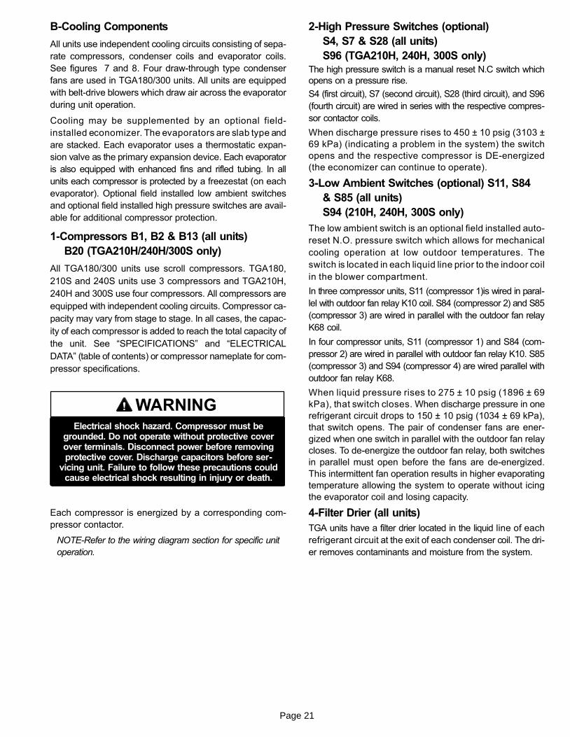
B−Cooling Components
All units use independent cooling circuits consisting of sepa-
rate compressors, condenser coils and evaporator coils.
See figures 7 and 8. Four draw−through type condenser
fans are used in TGA180/300 units. All units are equipped
with belt-drive blowers which draw air across the evaporator
during unit operation.
Cooling may be supplemented by an optional field-
installed economizer. The evaporators are slab type and
are stacked. Each evaporator uses a thermostatic expan-
sion valve as the primary expansion device. Each evaporator
is also equipped with enhanced fins and rifled tubing. In all
units each compressor is protected by a freezestat (on each
evaporator). Optional field installed low ambient switches
and optional field installed high pressure switches are avail-
able for additional compressor protection.
1−Compressors B1, B2 & B13 (all units)
B20 (TGA210H/240H/300S only)
All TGA180/300 units use scroll compressors. TGA180,
210S and 240S units use 3 compressors and TGA210H,
240H and 300S use four compressors. All compressors are
equipped with independent cooling circuits. Compressor ca-
pacity may vary from stage to stage. In all cases, the capac-
ity of each compressor is added to reach the total capacity of
the unit. See �SPECIFICATIONS" and �ELECTRICAL
DATA" (table of contents) or compressor nameplate for com-
pressor specifications.
WARNINGElectrical shock hazard. Compressor must be
grounded. Do not operate without protective coverover terminals. Disconnect power before removingprotective cover. Discharge capacitors before ser-
vicing unit. Failure to follow these precautions couldcause electrical shock resulting in injury or death.
Each compressor is energized by a corresponding com-
pressor contactor.
NOTE−Refer to the wiring diagram section for specific unit
operation.
2−High Pressure Switches (optional)
S4, S7 & S28 (all units)
S96 (TGA210H, 240H, 300S only)
The high pressure switch is a manual reset N.C switch which
opens on a pressure rise.
S4 (first circuit), S7 (second circuit), S28 (third circuit), and S96
(fourth circuit) are wired in series with the respective compres-
sor contactor coils.
When discharge pressure rises to 450 ± 10 psig (3103 ±
69 kPa) (indicating a problem in the system) the switch
opens and the respective compressor is DE−energized
(the economizer can continue to operate).
3−Low Ambient Switches (optional) S11, S84
& S85 (all units)
S94 (210H, 240H, 300S only)
The low ambient switch is an optional field installed auto-
reset N.O. pressure switch which allows for mechanical
cooling operation at low outdoor temperatures. The
switch is located in each liquid line prior to the indoor coil
in the blower compartment.
In three compressor units, S11 (compressor 1)is wired in paral-
lel with outdoor fan relay K10 coil. S84 (compressor 2) and S85
(compressor 3) are wired in parallel with the outdoor fan relay
K68 coil.
In four compressor units, S11 (compressor 1) and S84 (com-
pressor 2) are wired in parallel with outdoor fan relay K10. S85
(compressor 3) and S94 (compressor 4) are wired parallel with
outdoor fan relay K68.
When liquid pressure rises to 275 ± 10 psig (1896 ± 69
kPa), that switch closes. When discharge pressure in one
refrigerant circuit drops to 150 ± 10 psig (1034 ± 69 kPa),
that switch opens. The pair of condenser fans are ener-
gized when one switch in parallel with the outdoor fan relay
closes. To de−energize the outdoor fan relay, both switches
in parallel must open before the fans are de−energized.
This intermittent fan operation results in higher evaporating
temperature allowing the system to operate without icing
the evaporator coil and losing capacity.
4−Filter Drier (all units)
TGA units have a filter drier located in the liquid line of each
refrigerant circuit at the exit of each condenser coil. The dri-
er removes contaminants and moisture from the system.

Page 22
5−Freezestats S49, S50 & S53 (all units)
S95 (TAG210H/240H/300S only)
Each unit is equipped with a low temperature switch located on
a return bend of each evaporator coil. S49 (first circuit), S50
(second circuit) and S53 (third circuit) are located on the
corresponding evaporator coils. On the 210H, 240H and
300S models, S95 is located on the fourth circuit.
Each freezestat is wired in series with the corresponding
compressor contactor. Each freezestat is an auto−reset
switch which opens at 29°F + 3°F (-1.7°C + 1.7°C) on a tem-
perature drop and closes at 58°F + 4°F (14.4°C + 2.2°C)
on a temperature rise. To prevent coil icing, Freezestats
open during compressor operation to temporarily dis-
able the respective compressor until the coil tempera-
ture rises.
6−Condenser Fans B4, B5, B21 & B22
See SPECIFICATIONS tables at the front of this manual
for specifications of condenser fans used in all units. All
condenser fans used have single−phase motors. The fan
assembly may be removed for servicing and cleaning.
C−Blower Compartment
The blower compartment in TGA180/300 units is located
between the evaporator coil and the compressor / control sec-
tion on the opposite side of the condenser coil. The blower as-
sembly is accessed by removing the screws on either side of
the sliding base. The base pulls out as shown in figure 11.
1−Blower Wheels
All TGA180/300 units have two 15 in. x 15 in. (381 mm x 381
mm) blower wheels. Both wheels are driven by one motor
mounted on a single shaft. Shaft bearings are equipped with
grease ports for service.
2−Indoor Blower Motor B3
All units use three-phase single-speed blower motors. CFM
adjustments are made by adjusting the motor pulley (sheave).
Motors are equipped with sealed ball bearings. All motor speci-
fications are listed in the SPECIFICATIONS (table of contents)
in the front of this manual. Units may be equipped with motors
manufactured by various manufacturers, therefore electrical
FLA and LRA specifications will vary. See unit rating plate for
information specific to your unit.
OPERATION / ADJUSTMENT
Blower Operation
Initiate blower demand at thermostat according to instruc-
tions provided with thermostat. Unit will cycle on thermostat
demand. The following steps apply to applications using a
typical elector−mechanical thermostat.
1− Blower operation is manually set at the thermostat sub-
base fan switch. With fan switch in ON position, blow-
ers will operate continuously.
2− With fan switch in AUTO position, the blowers will cycle
with demand. Blowers and entire unit will be off when
system switch is in OFF position.
Blower Access
The blower assembly is secured to a sliding base which al-
lows the entire assembly to be pulled out of the unit. See
figure 11.
1− Remove the clamp which secures the blower wiring to
the blower motor base.
2− Remove and retain screws on either side of sliding
base. Pull base toward outside of unit. When pulling the
base out further than 12" (305mm), disconnect wiring
to K3 blower contactor T1, T2, and T3. Pull wiring to-
ward blower to allow enough slack to slide the base out
further.
3− Slide base back into original position when finished
servicing. Replace the clamp and blower wiring in the
previous location on the blower motor base. Reconnect
wiring to K3 if it was disconnected.
4− Replace retained screws on either side of the sliding
base.
Determining Unit Air Volume
1− The following measurements must be made with a dry in-
door coil. Run blower without cooling demand. Air filters
must be in place when measurements are taken.
2− With all access panels in place, measure static pres-
sure external to unit (from supply to return).
3− Measure the indoor blower wheel RPM.
4− Refer to blower tables in BLOWER DATA (table of con-
tents) in the front of this manual. Use static pressure and
RPM readings to determine unit air volume.
5− The RPM can be adjusted at the motor pulley. Loosen Al-
len screw and turn adjustable pulley clockwise to increase
RPM. Turn counterclockwise to decrease RPM. See fig-
ure 11 for TGA180/300 units.

Page 23
Blower Belt Adjustment
Maximum life and wear can be obtained from belts only if
proper pulley alignment and belt tension are main-
tained. Tension new belts after a 24−48 hour period of op-
eration. This will allow belt to stretch and seat grooves.
Make sure blower and motor pulley are aligned as shown in
figure 9.
FIGURE 9
PULLEY ALIGNMENT
BELTBLOWERPULLEY
MOTORPULLEY
NOT ALIGNED
ALIGNED
1− Loosen four bolts securing motor base to mounting
frame. See figure 11.
2− To relieve belt tension −
Turn adjusting bolt to the right, or clockwise, to move
the motor upward and loosen the belt. This decreases
the distance between the blower motor pulley and the
blower housing pulley.
To increase belt tension −
Turn the adjusting bolt to the left, or counterclockwise
to increase belt tension. This increases the distance
between motor pulley and blower housing pulley (mo-
tor moves downward and tightens belt).
3− Tighten four bolts securing motor base to mounting
frame.
IMPORTANT − Align top edges of blower motor base and
mounting frame base parallel before tightening bolts on the
both sides of base. Motor shaft and blower shaft must be
parallel.
Check Belt Tension
Overtensioning belts shortens belt and bearing life. Check
belt tension as follows:
1− Measure span length X. See figure 10.
2− Apply perpendicular force to center of span (X) with
enough pressure to deflect belt 1/64" for every inch of
span length or 1.5mm per 100mm of span length.
Example: Deflection distance of a 40" span would be
40/64" or 5/8".
Example: Deflection distance of a 400mm span would
be 6mm.
3− Measure belt deflection force. For a used belt, the
deflection force should be 5 lbs. (35kPa). A new belt
deflection force should be 7 lbs. (48kPa).
A force below these values indicates an underten-
sioned belt. A force above these values indicates an
overtensioned belt.
MEASURE BELT TENSION
FIGURE 10
DEFLECTION 1/64" PER INCH OF SPANOR 1.5mm PER 100mm OF SPAN
FORCE

Page 24
FIGURE 11
BLOWER ASSEMBLY
TO INCREASE BELT TENSION
1−Loosen four screws securing blower motor tosliding base.
2−Turn adjusting screw to the left, or counter-clockwise, to move the motor downward andtighten the belt.
3−Tighten four screws.
TO INCREASE CFMLOOSEN ALLEN SCREW &
TURN PULLEY CLOCKWISE
TO DECREASE CFMTURN PULLEY
COUNTERCLOCKWISE
BLOWERWHEEL
BLOWERMOTOR
PULLEY
BLOWERASSEMBLY
SLIDING BASE
BELT TENSIONADJUSTING
SCREW
LOOSEN (4) SCREWS ONMOTOR BASE TO ALLOW
MOTOR TO MOVE.
REMOVE SCREWS TOSLIDE BLOWER
ASSEMBLY OUT OF UNITPULLEY
MOTOR ALLENSCREW
SIDE VIEW
TGA180/300 HEATING COMPONENTS
FIGURE 12
COMBUSTION AIR INDUCERPROVE SWITCH S18
(FIRST HEAT SECTION)
CONDENSERDIVIDER PANEL
S10 AND S99 ON DRIPSHIELD BEHIND
BLOWER HOUSING
COMBUSTION AIR INDUCERPROVE SWITCH S45 NOT SHOWN
(SECOND HEAT SECTION)
1st HEAT SECTION
2nd HEAT SECTION
D−GAS HEAT COMPONENTS See SPECIFICATIONS tables or unit nameplate for
Btuh capacities. TGA180/300 units are equipped with
two identical gas heat sections (gas heat section one
and gas heat section two).
Heat sections consists of heat exchanger and buner box
assembly. See figures 13 and 14. Flexible pipe will feed
supply gas to both sections. If for service the flexible
connection must broken, hand tighten then turn addi-
tional 1/4" with a wrench for metal to metal seal (do not
overtighten).
NOTE − Do not use thread sealing compound on flex pipe
flare connections.
1−Heat Exchanger (Figure 13)
The TGA units use aluminized steel inshot burners with match-
ing tubular aluminized steel heat exchangers and two-stage
redundant gas valves. TGA180/300 units use two six tube/
burners for standard heat, two nine tube/burners for medium
heat and two eleven tube/burner for high heat. Burners in all
units use a burner venturi to mix gas and air for proper com-
bustion. Combustion takes place at each tube entrance. As hot
combustion gases are drawn upward through each tube by the
combustion air inducer, exhaust gases are drawn out the top
and fresh air/gas mixture is drawn in at the bottom. Heat is
transferred to the air stream from all surfaces of the heat ex-
changer tubes. The supply air blowers force air across all sur-
faces of the tubes to extract the heat of combustion. The shape
of the tubes ensures maximum heat exchange.
The gas valves accomplish staging by allowing more or less
gas to the burners as called for by heating demand.

Page 25
FIGURE 13
TGA HEAT EXCHANGER(one heat section shown)
BURNERS
COMBUSTIONAIR INDUCER
(B6), (B15)
FLUE EXTENSION
GAS VALVE(GV1), (GV3)
HEATEXCHANGER
TUBE
ROLLOUT SWITCH(S47), (S69)
2−Burner Box Assembly (Figure 14)
Each heat section is equipped with a burner box assembly.
The burner assembly consists of a spark electrode, flame
sensing electrode and gas valve. Each assembly is controlled
by the heat sections ignition control board (A3 section one and
A12 section two)
BurnersAll units use inshot burners (see figure 14). Burners are
factory set and do not require adjustment. A peep hole
with cover is furnished in the heating access panel
for flame viewing. Always operate the unit with the
access panel in place.
Burners can be removed individually for service.
Burner maintenance and service is detailed in the
SERVICE CHECKS section of this manual.
OrificeEach burner uses an orifice which is precisely matched to
the burner input. The orifice is threaded into the burner
manifold. The burner is supported by the orifice and will
easily slide off for service.
NOTE−Do not use thread sealing compound on the ori-
fices. Using thread sealing compound may plug the ori-
fices.
Each orifice and burner are sized specifically to the unit.
Refer to Repair Parts Listing for correct sizing information.
FIGURE 14
BURNER BOX ASSEMBLY
GAS MANIFOLD
FLAMESENSOR
GASVALVE
(GV1), GV3)
BURNERS
FLAMEROLLOUT
LIMIT(S47), (S69)
SPARKELECTRODE
Page 26
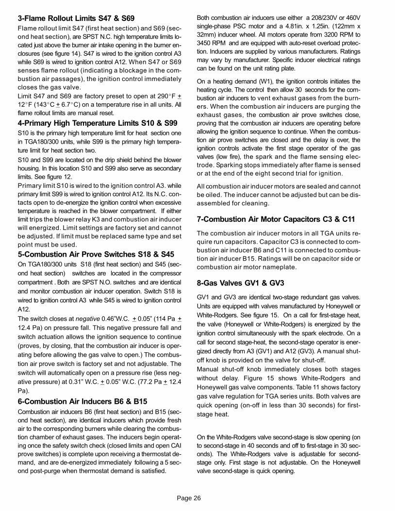
3−Flame Rollout Limits S47 & S69
Flame rollout limit S47 (first heat section) and S69 (sec-
ond heat section), are SPST N.C. high temperature limits lo-
cated just above the burner air intake opening in the burner en-
closures (see figure 14). S47 is wired to the ignition control A3
while S69 is wired to ignition control A12. When S47 or S69
senses flame rollout (indicating a blockage in the com-
bustion air passages), the ignition control immediately
closes the gas valve.
Limit S47 and S69 are factory preset to open at 290�F +
12�F (143�C + 6.7�C) on a temperature rise in all units. All
flame rollout limits are manual reset.
4−Primary High Temperature Limits S10 & S99
S10 is the primary high temperature limit for heat section one
in TGA180/300 units, while S99 is the primary high tempera-
ture limit for heat section two.
S10 and S99 are located on the drip shield behind the blower
housing. In this location S10 and S99 also serve as secondary
limits. See figure 12.
Primary limit S10 is wired to the ignition control A3. while
primary limit S99 is wired to ignition control A12. Its N.C. con-
tacts open to de−energize the ignition control when excessive
temperature is reached in the blower compartment. If either
limit trips the blower relay K3 and combustion air inducer
will energized. Limit settings are factory set and cannot
be adjusted. If limit must be replaced same type and set
point must be used.
5−Combustion Air Prove Switches S18 & S45
On TGA180/300 units S18 (first heat section) and S45 (sec-
ond heat section) switches are located in the compressor
compartment . Both are SPST N.O. switches and are identical
and monitor combustion air inducer operation. Switch S18 is
wired to ignition control A3 while S45 is wired to ignition control
A12.
The switch closes at negative 0.46"W.C. + 0.05" (114 Pa +
12.4 Pa) on pressure fall. This negative pressure fall and
switch actuation allows the ignition sequence to continue
(proves, by closing, that the combustion air inducer is oper-
ating before allowing the gas valve to open.) The combus-
tion air prove switch is factory set and not adjustable. The
switch will automatically open on a pressure rise (less neg-
ative pressure) at 0.31" W.C. + 0.05" W.C. (77.2 Pa + 12.4
Pa).
6−Combustion Air Inducers B6 & B15
Combustion air inducers B6 (first heat section) and B15 (sec-
ond heat section), are identical inducers which provide fresh
air to the corresponding burners while clearing the combus-
tion chamber of exhaust gases. The inducers begin operat-
ing once the safety switch check (closed limits and open CAI
prove switches) is complete upon receiving a thermostat de-
mand, and are de−energized immediately following a 5 sec-
ond post−purge when thermostat demand is satisfied.
Both combustion air inducers use either a 208/230V or 460V
single-phase PSC motor and a 4.81in. x 1.25in. (122mm x
32mm) inducer wheel. All motors operate from 3200 RPM to
3450 RPM and are equipped with auto-reset overload protec-
tion. Inducers are supplied by various manufacturers. Ratings
may vary by manufacturer. Specific inducer electrical ratings
can be found on the unit rating plate.
On a heating demand (W1), the ignition controls initiates the
heating cycle. The control then allow 30 seconds for the com-
bustion air inducers to vent exhaust gases from the burn-
ers. When the combustion air inducers are purging the
exhaust gases, the combustion air prove switches close,
proving that the combustion air inducers are operating before
allowing the ignition sequence to continue. When the combus-
tion air prove switches are closed and the delay is over, the
ignition controls activate the first stage operator of the gas
valves (low fire), the spark and the flame sensing elec-
trode. Sparking stops immediately after flame is sensed
or at the end of the eight second trial for ignition.
All combustion air inducer motors are sealed and cannot
be oiled. The inducer cannot be adjusted but can be dis-
assembled for cleaning.
7−Combustion Air Motor Capacitors C3 & C11
The combustion air inducer motors in all TGA units re-
quire run capacitors. Capacitor C3 is connected to com-
bustion air inducer B6 and C11 is connected to combus-
tion air inducer B15. Ratings will be on capacitor side or
combustion air motor nameplate.
8−Gas Valves GV1 & GV3
GV1 and GV3 are identical two−stage redundant gas valves.
Units are equipped with valves manufactured by Honeywell or
White−Rodgers. See figure 15. On a call for first−stage heat,
the valve (Honeywell or White−Rodgers) is energized by the
ignition control simultaneously with the spark electrode. On a
call for second stage−heat, the second−stage operator is ener-
gized directly from A3 (GV1) and A12 (GV3). A manual shut−
off knob is provided on the valve for shut−off.
Manual shut-off knob immediately closes both stages
without delay. Figure 15 shows White−Rodgers and
Honeywell gas valve components. Table 11 shows factory
gas valve regulation for TGA series units. Both valves are
quick opening (on−off in less than 30 seconds) for first−
stage heat.
On the White−Rodgers valve second−stage is slow opening (on
to second−stage in 40 seconds and off to first−stage in 30 sec-
onds). The White−Rodgers valve is adjustable for second−
stage only. First stage is not adjustable. On the Honeywell
valve second−stage is quick opening.

Page 27
GAS VALVE REGULATION FOR TGA UNITS
Maximum Inlet
Pressure
Operating Pressure(outlet) Factory Setting
13.0"W.C.3232Pa
Natural L.P.
3.7+0.3"W.C.920+75Pa
Low High Low High
1.6+0.2"W.C.398+50Pa
10.5+0.5"W.C.2611+7124Pa
5.5+0.3"W.C.1368+75Pa
TABLE 11
FIGURE 15
1st STAGEADJUSTMENT
2nd STAGEADJUSTMENT
INLETPRESSURE
TAP
MANIFOLDPRESSURE
TAP
HONEYWELL VR8305/VR8205 GAS VALVE
GAS VALVE SHOWNIN �OFF" POSITION
WHITE−RODGERS 36C76 GAS VALVE
D−1
GV−1C−1C2
GV−2
MANIFOLDPRESSURETAP (SIDE)
STAGE 2 MANUAL MANIFOLDPRESSURE ADJUSTMENT
SCREW UNDER CAP
INLETPRESSURETAP (SIDE)
GAS VALVESHOWN IN �OFF"
POSITION
9−Spark Electrodes
An electrode assembly is used for ignition spark. Two
identical electrodes are used (one for each gas heat sec-
tion). The electrode is mounted through holes on the left-
most end of the burner support. The electrode tip pro-
trudes into the flame envelope of the adjacent burner. The
electrode assembly is fastened to burner supports and can be
removed for service without removing any part of the burners.
During ignition, spark travels through the spark electrode (fig-
ure 16) and ignites the left burner. Flame travels from burner to
burner until all are lit.
The spark electrode is connected to the ignition control by a 8
mm silicone-insulated stranded high voltage wire. The wire
uses 1/4" (6.35 mm)female quick connect.
IMPORTANT
In order to maximize spark energy to electrode,high voltage wire should touch unit cabinet as
little as possible
FIGURE 16
SPARK ELECTRODE
SPARK GAP
SHOULD BE 1/8"
(3mm)
10−Flame Sensors (Figure 17)A flame sensor is located on the right side of each burner
support. The sensor is mounted through a hole in the burn-
er support and the tip protrudes into the flame envelope of the
right most burner. The sensor assembly is fastened to burner
supports and can be removed for service without removing any
part of the burners.
When flame is sensed by the flame sensor (indicated by
microamp signal through the flame) sparking stops imme-
diately. During operation, flame is sensed by current
passed along the ground electrode (located on the spark
electrode), through the flame and into the sensing elec-
trode. The ignition control allows the gas valve to stay
open as long as a flame signal (current passed through the
flame) is sensed.
FIGURE 17
SIDE VIEW SENSOR
1−3/4"(45mm)
3/8"(10mm)
BURNER
FLAME SENSOR

Page 28
II−PLACEMENT AND INSTALLATION
Make sure the unit is installed in accordance with the
installation instructions and all applicable codes. See
accessories section for conditions requiring use of the
optional roof mounting frame (LARMF18/36 or
LARMFH18/24).
III−STARTUP − OPERATION
Refer to startup directions and to the unit wiring diagram
when servicing. See unit nameplate for minimum circuit
ampacity and maximum fuse size.
A−Preliminary and Seasonal Checks
1− Make sure the unit is installed in accordance with the
installation instructions and applicable codes.
2− Inspect all electrical wiring, both field and factory installed
for loose connections. Tighten as required. Refer to unit
diagram located on inside of unit control box cover.
3− Check to ensure that refrigerant lines are in good
condition and do not rub against the cabinet or other
refrigerant lines.
4− Check voltage at the disconnect switch (if applicable)
or TB2. Voltage must be within the range listed on the
nameplate. If not, consult the power company and
have the voltage corrected before starting the unit.
5− Recheck voltage and amp draw with unit running. If
voltage is not within range listed on unit nameplate,
stop unit and consult power company. Refer to unit
nameplate for maximum rated load amps.
6− Inspect and adjust blower belt (see section on Blower
Compartment − Blower Belt Adjustment).
B−Heating Startup
FOR YOUR SAFETY READ BEFORE LIGHTING
Danger of explosion. Can cause injury or
product or property damage. If over-
heating occurs or if gas supply fails to
shut off, shut off the manual gas valve to
the appliance before shutting off electri-
cal supply.
WARNING!
Electric shock hazard. Can causeinjury or death. Before attempting toperform any service or maintenance,turn the electrical power to unit OFFat disconnect switch(es). Unit may
have multiple power supplies.
WARNING!
WARNINGSMOKE POTENTIAL
The heat exchanger in this unit could be a source ofsmoke on initial firing. Take precautions with respectto building occupants and property. Vent initial sup-ply air outside when possible.
BEFORE LIGHTING smell all around the appliance area for
gas. Be sure to smell next to the floor because some gas is
heavier than air and will settle on the floor.
Use only your hand to push in or turn the gas control knob.
Never use tools. If the knob will not push in or turn by hand,
do not try to repair it, call a qualified service technician.
Force or attempted repair may result in a fire or explosion.
IMPORTANT
This unit is equipped with an automatic sparkignition system. Do not attempt to light manually.
In case of a safety shutdown, move thermostat switch to
OFF and return the thermostat switch to HEAT to reset igni-
tion control.
−Placing Furnace In Operation
Gas Valve Operation for White Rodgers 36C andHoneywell VR8205Q/VR8305Q (figure 15)
1− Set thermostat to lowest setting.
2− Turn off all electrical power to appliance.
3− This appliance is equipped with an ignition device
which automatically lights the burner. Do not try to light
the burner by hand.
4− Open or remove the heat section access panel.
5− Turn the knob on the gas valve clockwise to �OFF".
Depress 36C knob slightly. Do not force.
6− Wait five (5) minutes to clear out any gas. If you then
smell gas, STOP! Immediately call your gas suppli-
er from a neighbor’s phone. Follow the gas supplier’s
instructions. If you do not smell gas, go to the next step.
7− Turn the knob on the gas valve counterclockwise
to �ON". Do not force.
8− Close or replace the heat section access panel.
9− Turn on all electrical power to appliance.
10− Set thermostat to desired setting.
11− The combustion air inducer will start. The burners will
light within 40 seconds.
12− If the appliance does not light the first time (gas line not
fully purged), it will attempt up to two more ignitions
before locking out.
13− If lockout occurs, repeat steps 1 through 10.
14− If the appliance will not operate, follow the instructions
�Turning Off Gas to Appliance" and call your service
technician or gas supplier.
Turning Off Gas to Appliance
1− If using an electromechanical thermostat, set to the
lowest setting.

Page 29
2− Before performing any service, turn off all electrical
power to the appliance.
3− Open or remove the heat section access panel.
4− Turn the knob on the gas valve clockwise to �OFF".
Depress 36C knob slightly. Do not force.
C−Safety or Emergency Shutdown
Turn off power and main manual shut off valve to unit.
D−Cooling Start Up
The thermostat specified for use on this unit has three cool-
ing outputs.
1− Remove coil covers before starting unit.
2− Initiate first and second stage cooling demands ac-
cording to instructions provided with thermostat.
3− First−stage thermostat demand will energize com-
pressor 1. Second−stage thermostat demand will en-
ergize compressor 2. Third−stage thermostat de-
mand will energize compressor 3 (and 4 on
4−compressor units only). On units with an economiz-
er, when outdoor air is acceptable, a first−stage de-
mand will energize the economizer; a second−stage
demand will energize compressor 1.
4− 180S & H, 210S, 240S,−
Units contain three refrigerant circuits or systems.
Evaporator and condenser coil refrigerant circuit 1
makes up stage 1 cooling. Evaporator and condenser
coil refrigerant circuit 2 makes up stage 2 cooling.
Evaporator and condenser coil refrigerant circuit 3
makes up stage 3 cooling. See figure 18.
210H, 240H, 300S −
Units contain four refrigerant circuits or systems. Evap-
orator and condenser coil refrigerant circuit 1 makes up
stage 1 cooling. Evaporator and condenser refrigerant
circuit 2 makes up stage 2 cooling. Evaporator and
condenser refrigerant circuit 3 and 4 makes up stage 3
cooling. See figure 19.
FIGURE 18
REFRIGERANT STAGESTHREE−COMPRESSOR UNITS
12
3
Circuit 1 = Stage 1Circuit 2 = Stage 2Circuit 3 = Stage 3
FIGURE 19
REFRIGERANT STAGESFOUR−COMPRESSOR UNITS
12
3
Circuit 1 = Stage 1Circuit 2 = Stage 2Circuit 3 & 4 = Stage 3
4
5− 180S & H, 210S, 240S,−
First−stage thermostat demand will energize condens-
er fans 1 and 2. See figure 20. Second−stage thermo-
stat demand will energize condenser fans 3 and 4.
Fans will continue to operate with additional thermostat
demands.
210H, 240H, 300S −
First−stage thermostat demand will energize condens-
er fans 1 and 2. See figure 20. Third−stage thermostat
demand will energize condenser fans 3 and 4.
CONDENSER FANS
FIGURE 20
COND.FAN 2
COND.FAN 1
COND.FAN 4
COND.FAN 3
1 2 3 4
compressors
evaporator coil
6− Each refrigerant circuit is separately charged with R−22
refrigerant. See unit rating plate for correct amount of
charge.
7− Refer to Cooling Operation and Adjustment section for
proper method to check refrigerant charge.

Page 30
IV−CHARGING
WARNINGRefrigerant can be harmful if it is inhaled. Refrigerantmust be used and recovered responsibly.
Failure to follow this warning may result in person-al injury or death.
WARNING−Do not exceed nameplate charge under anycondition.
This unit is factory charged and should require no further
adjustment. If the system requires charge, reclaim the
charge, evacuate the system, and add required nameplate
charge.
NOTE − System charging is not recommended below 60°F
(15°C). In temperatures below 60°F (15°C) , the charge
must be weighed into the system.
If weighing facilities are not available, or to check the
charge, use the following procedure:
1− Attach gauge manifolds and operate unit in cooling
mode until system stabilizes (approximately five min-
utes). Make sure outdoor air dampers are closed.
2− Check each system separately with all stages operat-
ing.
3− Use a thermometer to accurately measure the outdoor
ambient temperature.
4− Apply the outdoor temperature to tables 12 through 18
to determine normal operating pressures.
5− Compare the normal operating pressures to the pres-
sures obtained from the gauges. Minor variations in
these pressures may be expected due to differences in
installations. Significant differences could mean that
the system is not properly charged or that a problem
exists with some component in the system. Correct
any system problems before proceeding.
6− If discharge pressure is high, remove refrigerant from
the system. If discharge pressure is low, add refrigerant
to the system.
� Add or remove charge in increments.
� Allow the system to stabilize each time refrigerant
is added or removed.
7− Use the following approach method along with the nor-
mal operating pressures to confirm readings.
TABLE 12TGA180S NORMAL OPERATING PRESSURES
OutdoorCoil En-tering
Air Temp
CIRCUIT 1 CIRCUIT 2 CIRCUIT 3
Dis.+10psig
Suc.+5
psig
Dis.+10psig
Suc.+5
psig
Dis.+10psig
Suc.+5
psig
65°F 172 75 178 78 181 78
75°F 199 77 205 80 210 80
85°F 228 79 237 82 242 81
95°F 258 80 271 83 274 82
105°F 293 82 309 84 312 84
115°F 331 83 348 85 350 85
TABLE 13TGA180H NORMAL OPERATING PRESSURES
OutdoorCoil En-tering
Air Temp
CIRCUIT 1 CIRCUIT 2 CIRCUIT 3
Dis.+10psig
Suc.+5
psig
Dis.+10psig
Suc.+5
psig
Dis.+10psig
Suc.+5
psig
65°F 158 72 159 74 158 74
75°F 183 76 186 79 184 78
85°F 210 78 214 81 211 79
95°F 239 79 245 83 241 81
105°F 270 81 278 84 273 82
115°F 304 82 313 86 306 84
TABLE 14TGA210S NORMAL OPERATING PRESSURES
OutdoorCoil En-tering
Air Temp
CIRCUIT 1 CIRCUIT 2 CIRCUIT 3
Dis.+10psig
Suc.+5
psig
Dis.+10psig
Suc.+5
psig
Dis.+10psig
Suc.+5
psig
65°F 188 66 191 67 194 71
75°F 213 69 217 70 220 73
85°F 242 71 247 74 252 74
95°F 275 73 281 76 286 76
105°F 308 75 315 77 321 77
115°F 347 77 355 79 361 79

Page 31
TABLE 15TGA210H NORMAL OPERATING PRESSURES
OutdoorCoil En-tering
Air Temp
CIRCUIT 1 CIRCUIT 2 CIRCUIT 3 CIRCUIT 4
Dis.+10psig
Suc.+5
psig
Dis.+10psig
Suc.+5
psig
Dis.+10psig
Suc.+5
psig
Dis.+10psig
Suc.+5
psig
65°F 170 77 173 80 172 80 168 80
75°F 197 78 198 81 197 81 193 81
85°F 223 79 225 82 225 82 221 82
95°F 255 81 255 83 257 83 252 83
105°F 289 83 287 84 293 85 287 85
115°F 329 85 323 86 333 87 327 87
TABLE 16TGA240S NORMAL OPERATING PRESSURES
OutdoorCoil
EnteringAir Temp
CIRCUIT 1 CIRCUIT 2 CIRCUIT 3
Dis.+10psig
Suc.+5
psig
Dis.+10psig
Suc.+5
psig
Dis.+10psig
Suc.+5
psig
65°F 185 69 182 73 183 72
75°F 212 71 209 75 210 74
85°F 236 72 233 75 234 75
95°F 267 73 265 76 264 75
105°F 297 74 301 77 300 76
115°F 335 76 340 78 338 78
TABLE 17TGA240H NORMAL OPERATING PRESSURES
OutdoorCoil En-tering
Air Temp
CIRCUIT 1 CIRCUIT 2 CIRCUIT 3 CIRCUIT 4
Dis.+10psig
Suc.+5
psig
Dis.+10psig
Suc.+5
psig
Dis.+10psig
Suc.+5
psig
Dis.+10psig
Suc.+5
psig
65°F 179 75 181 79 174 79 176 79
75°F 207 76 208 81 203 79 204 80
85°F 239 78 238 82 233 80 234 81
95°F 272 80 270 83 266 83 266 83
105°F 307 83 303 84 301 84 300 85
115°F 351 85 342 85 343 86 342 86
TABLE 18TGA300S NORMAL OPERATING PRESSURES
OutdoorCoil En-tering
Air Temp
CIRCUIT 1 CIRCUIT 2 CIRCUIT 3 CIRCUIT 4
Dis.+10psig
Suc.+5
psig
Dis.+10psig
Suc.+5
psig
Dis.+10psig
Suc.+5
psig
Dis.+10psig
Suc.+5
psig
65°F 185 69 183 70 186 72 179 71
75°F 213 72 210 74 215 76 207 75
85°F 247 75 241 77 249 78 240 78
95°F 280 77 271 78 281 80 271 79
105°F 320 79 309 79 317 81 307 80
115°F 361 81 346 80 358 82 345 82
C−Charge Verification − Approach Method
1− Using the same thermometer, compare liquid tempera-
ture to outdoor ambient temperature.
Approach Temperature = Liquid temperature minus
ambient temperature.
2− Approach temperatures should match values in table
19. An approach temperature greater than this value in-
dicates an undercharge. An approach temperature
less than this value indicates an overcharge.
3− Do not use the approach method if system pressures
do not match pressures in tables 12 through 18. The
approach method is not valid for grossly over or under-
charged systems.
TABLE 19APPROACH TEMPERATURES
UnitLiquid Temp. Minus Ambient Temp.
1st Stage 2nd Stage 3rd Stage 4th Stage
180S210S240S180H
7°F + 1 (3.9°C + 0.5)
7°F + 1 (3.9°C + 0.5)
7°F + 1 (3.9°C + 0.5)
NA
210H9°F + 1
(5°C + 0.5)7°F + 1
(3.9°C + 0.5)8°F + 1
(4.4°C + 0.5)8°F + 1
(4.4°C + 0.5)
240H10°F + 1
(5.6°C + 0.5)9°F + 1
(5°C + 0.5)9°F + 1
(5°C + 0.5)10°F + 1
(5.6°C + 0.5)
300S14°F + 1
(7.8°C + 0.5)12°F + 1
(6.7°C + 0.5)12°F + 1
(6.7°C + 0.5)12°F + 1
(6.7°C + 0.5)

Page 32
V− SYSTEMS SERVICE CHECKS
A−Heating System Service Checks
All TGA units are C.S.A. design certified without modifi-
cation.
Before checking piping, check with gas company or au-
thorities having jurisdiction for local code requirements.
Refer to the TGA Installation instruction for more infor-
mation.
UNIT
GROUNDJOINT UNION
MANUAL MAINSHUT−OFF VALVE
(REFER TO LOCAL CODES)
GAS PIPINGSUPPORT
DRIP LEG
ROOFMOUNTING
FRAME
GAS PIPING COMPONENTSREFER TO INSTALLATION INSTRUCTIONS
VALVE
CAP HERE TOISOLATE VALVE
WHEN PRESSURETESTING LINE
FIGURE 21
1−Gas Piping
Gas supply piping must not allow more than 0.5"W.C.
(124.3 Pa) drop in pressure between the gas meter and
the unit. Supply gas pipe must not be smaller than the unit
gas connection. Refer to installation instructions for de-
tails.
2−Testing Gas Piping
NOTE−In case emergency shutdown is required, turn off
the main manual shut-off valve and disconnect the main
power to the unit. These controls should be properly la-
beled by the installer.
When pressure testing gas lines, the gas valve must be dis-
connected and isolated. Gas valves can be damaged if
subjected to more than 0.5 psig [14"W.C. (3481 Pa)]. See
figure 21.
When checking piping connection for gas leaks, use the
preferred means. Common kitchen detergents can
cause harmful corrosion on various metals used in gas
piping. The use of specialty Gas Leak Detector is strong-
ly recommended.
Do not use matches, candles, flame or any other source of
ignition to check for gas leaks.
3−Testing Gas Supply Pressure
When testing gas supply pressure, connect test gauge to the
inlet pressure tap located on unit gas valve GV1 and or
GV3. Test supply gas pressure with unit firing at maximum
rate (both stages energized). Make sure the reading falls
within the range of the following values. Low pressure may
result in erratic operation or �underfire." High pressure can
result in permanent damage to the gas valve or �overfire."
For natural gas units, operating pressure at the unit gas
connection must be between 4.7"W.C. and 11.0"W.C.
(1168 Pa and 2735 Pa). For L.P. gas units, operating
pressure at the unit gas connection must be between
11.0"W.C. and 13.0"W.C. (2735 Pa and 3232 Pa).
On multiple unit installations, each unit should be checked
separately while operating at maximum rate, beginning with
the one closest to the supply gas main and progressing to
the one furthest from the main. Multiple units should also
be tested with and without the other units operating.
Supply pressure must fall within the range listed in the
previous paragraph.
4−Check and Adjust Manifold Pressure
After line pressure has been checked and adjusted,
check manifold pressure. Move test gauge to the outlet
pressure tap located on unit gas valve GV1 and or GV3.
See figure 15 for location of pressure tap on the gas
valve.
The manifold pressure is factory set and should not re-
quire adjustment. If manifold pressure is incorrect and no other
source of improper manifold pressure can be found, the valve
must be replaced. See figure 15 for location of gas valve (man-
ifold pressure) adjustment screw.
The gas valve should completely and immediately cycle off in
the event of gas or power failure. The manual shut-off knob can
be used to immediately shut off gas supply.
CAUTIONFor safety, connect a shut-off valve between themanometer and the gas tap to permit shut off of
gas pressure to the manometer.
Manifold Adjustment Procedure
1− Connect test gauge to the outlet pressure tap on the
gas valve. Start the unit (call for second stage heat)
and allow five minutes for the unit to reach steady
state.
2− While waiting for the unit to stabilize, notice the
flame. The flame should be stable without flashback
and should not lift from the burner heads. Natural
gas should burn basically blue with some clear
streaks. L.P. gas should burn mostly blue with some
clear yellow streaks.
3− After allowing the unit to stabilize for five minutes, re-
cord the manifold pressure and compare to the values
given in table 11.

Page 33
5−High Altitude
Units may be installed at altitudes up to 2000 feet (610 m)
above sea level without any modification. At altitudes
above 2000 feet (610 m), units must be derated to match
the gas manifold pressures shown in table 20.
NOTE - This is the only permissible derate for these units.
TABLE 20
Altitude − ft. (m)
Gas Manifold Pressure in. w.g. (kPa)
Natural LP (Propane)
0 − 2000 ( 610) 3.7 (0.92) 10.5 (2.61)
2001 − 3000 ( 610 − 915) 3.6 (0.90) 10.2 (2.54)
3001 − 4000 ( 915 − 1220) 3.5 (0.87) 9.9 (2.46)
4001 − 5000 (1220 − 1525) 3.4 (0.85) 9.6 (2.39)
5001 − 6000 (1525 − 1830) 3.3 (0.82) 9.4 (2.34)
6001 − 7000 (1830 − 2135) 3.2 (0.80) 9.1 (2.26)
7001 − 8000 (2135 − 2440) 3.1 (0.77) 8.8 (2.19)
*Contact Technical Support for altitudes higher than 8000 ft. (2400m).
CAUTION
Disconnect heating demand as soon as an accu-rate reading has been obtained.
6−Proper Gas Flow
To check for proper gas flow to burners, determine Btuh in-
put from unit rating plate or the gas heating capacity in the
SPECIFICATIONS tables. Divide this input rating by the
Btuh per cubic foot of available gas. Result is the number of
cubic feet per hour required. Determine the flow of gas
through gas meter for two minutes and multiply by 30 to get
hourly flow of gas to the burners.
NOTE − To obtain accurate reading, shut off all other gas
appliances connected to meter.
TABLE 21
Unit in Btu’sSeconds for
NaturalSeconds for
Propane
260,000 14 35
360,000 10 30
480,000 8 19
7−Heat Exchanger
To Access or Remove Heat Exchanger From Unit:
1− Turn off gas and electric power.
2− Remove access panel(s) and unit center mullion.
Loosen or remove corner mullion if necessary.
3− Remove gas valve, manifold assembly and burn-
ers.
4− Disconnect all wiring (label wiring) from heat section
components and remove combustion air inducer and
flue box. Pay careful attention to the order in which
gaskets and orifice are removed.
5− Support heat exchanger (to prevent it from falling
when final screws are removed.)
6− Remove screws supporting heat exchanger.
7− To install heat exchanger, reverse procedure. Be sure
to secure all wires and check plumbing and burner
plate for airtight seal. Screws must be torqued to 35
in.-lbs. to ensure proper operation.
8−Flame Sensing
Flame current is an electrical current which passes from the
ignition control through the sensor electrode during unit op-
eration. The current passes from the sensor through the
flame to the ground electrode (located on the flame elec-
trode) to complete a safety circuit. The electrodes should be
located so the tips are at least 1/2" (12.7 mm) inside the
flame envelope. Do not bend electrodes. To measure flame
current, follow the procedure on the following page:
CAUTIONElectrodes are not field adjustable. Any alter-
ations to the electrode may create a hazardouscondition that can cause property damage or
personal injury.

Page 34
1− Disconnect power to unit.
2− Remove lead from sensing electrode and install a
0−50DC microamp meter in series between the sens-
ing electrode and the sensing lead.
3− Reconnect power and adjust thermostat for
heating demand.
4− When flame is established, compare reading to table
22. Do not bend electrodes.
5− Disconnect power to unit before disconnecting meter.
Make sure sensor wire is securely reconnected
before reconnecting power to unit.
TABLE 22
ManufacturerNominal Signal
MicroampsDrop Out
JOHNSON 0.5 − 1.0 .09
NOTE−If the meter scale reads 0, the leads are re-
versed. Disconnect power and reconnect leads for
proper polarity.
B−Cooling System Service ChecksTGA units are factory charged and require no further adjust-
ment; however, charge should be checked periodically using
the approach method. The approach method compares actual
liquid temperature with the outdoor ambient temperature. See
section IV− CHARGING.
NOTE−When unit is properly charged discharge line pres-
sures should approximate those in tables 12 through 18.
VI−MAINTENANCE
Electric shock hazard. Can causeinjury or death. Before attempting toperform any service or maintenance,turn the electrical power to unit OFFat disconnect switch(es). Unit may
have multiple power supplies.
WARNING!
A−FiltersUnits are equipped with six 24 X 24 X 2" filters. Filters
should be checked and replaced when necessary with fil-
ters of like kind and size. Take note of air flow direction
marking on filter frame when reinstalling filters. See figure
22. Filters must be U.L.C. certified or equivalent for use in
Canada.
NOTE−Filters must be U.L.C. certified or equivalent foruse in Canada.
B−LubricationAll motors used in TGA units are factory lubricated, no
further lubrication is required.
Blower shaft bearings are prelubricated. For extended
bearing life, relubricate at least once every two years with a
lithium base grease such as Alvania 3 (Shell Oil), Chevron
BRB2 (Standard OIl) or Regal AFB2 (Texas Oil). Use a
hand grease gun for lubrication. Add only enough grease to
purge through the bearings so that a bead of grease ap-
pears at the seal lip contacts.
FIGURE 22
PULL TOREMOVEFILTERS
C−Burners
Periodically examine burner flames for proper appearance
during the heating season. Before each heating season ex-
amine the burners for any deposits or blockage which may
have occurred.
Clean burners as follows:
1− Turn off both electrical power and gas supply to unit.
2− Remove burner compartment access panel.
3− Remove two screws securing burners to burner sup-
port and lift the burners from the orifices. See figure 14.
Clean as necessary.
4− Locate the ignitor under the left burners. Check ignitor
spark gap with appropriately sized twist drills or feeler
gauges. See figure 16.
5− Reinstall burners and screws securing burners to burn-
er support.
WARNINGDanger of explosion. Can cause injury ordeath. Do not overtighten main burnermounting screws. Snug tighten only.
6− Replace access panel.
7− Restore electrical power and gas supply. Follow light-
ing instructions attached to unit and use inspection port
in access panel to check flame.

Page 35
D−Combustion Air InducerA combustion air proving switch checks combustion air in-
ducer operation before allowing heating sequence to con-
tinue. The sequence will not be allowed to continue if induc-
er is obstructed.
The combustion air inducer wheel should be checked and
cleaned prior to the heating season. It should be examined
periodically during the heating season to establish an ideal
cleaning schedule. With power supply disconnected, the
condition of the inducer wheel can be determined by re-
moving the vent pipe and inspecting the wheel through the
outlet opening.
Clean combustion air inducer as follows:
1− Shut off power supply and gas to unit.
2− Disconnect pressure switch air tubing from combustion
air inducer port.
3− Remove and retain screws securing combustion air in-
ducer to flue box. Remove and retain two screws from
bracket supporting vent connector.
4− Clean inducer wheel blades with a small brush and
wipe off any dust from housing. Clean accumulated
dust from front of flue box cover.
5− Return combustion air inducer motor and vent connec-
tor to original location and secure with retained screws.
It is recommended that the combustion air inducer gas-
ket be replaced during reassembly.
6− Clean combustion air inlet louvers on heat access pan-
el using a small brush.
E−Flue Passageway and Flue Box
1− Remove combustion air inducer assembly as de-
scribed in section D.
2− Remove flue box cover. Clean with a wire brush as re-
quired.
3− Clean tubes with a wire brush.
4− Reassemble the unit. The flue box cover gasket and
combustion air inducer gasket should also be replaced
during reassembly.
F−Supply Air Blower WheelAnnually inspect supply air blower wheel for accumulated
dirt or dust. Turn off power before attempting to remove ac-
cess panel or to clean blower wheel.
G−Evaporator CoilInspect and clean coil at beginning of each season. Clean
using mild detergent or commercial coil cleanser. Check
condensate drain pan and line, if necessary. Flush coil and
condensate drain with water taking care not to get insula-
tion, filters and return air ducts wet. Check connecting
lines and coil for evidence of oil and refrigerant leaks.
H−Condenser Coil
Clean condenser coil annually with detergent or commer-
cial coil cleaner and inspect monthly during the cooling sea-
son.
Condenser coils are made of two formed slabs. Dirt and de-
bris may become trapped between the slabs. To clean be-
tween slabs, carefully separate coil slabs and wash them
thoroughly. See figure 23. Flush coils with water following
cleaning.
Note − Remove all screws and gaskets prior to cleaning pro-
cedure and replace upon completion.
I−Electrical1− Check all wiring for loose connections.
2− Check for correct voltage at unit (unit operating).
3− Check amp−draw on both condenser fan motor and
blower motor.
Fan Motor Rating Plate ____ Actual ________
Indoor Blower Motor Rating Plate____ Actual____
TOP VIEW
CONDENSERCOILS
BLOWER
FIGURE 23
1− Remove unit top panel and both condenser access
panels.
2− Remove screws securing coil end plates to mullions.
3− Remove clips connecting coils slabs and separate
slabs 3−4" (76−102mm).
4− Clean coils with detergent or commercial coil cleaner.
5− Rinse thoroughly with water and reassemble.
CLEAN CONDENSER COILCONDENSER
ACCESS PANEL(same on other side)
INDOOR COIL

Page 36
VII−OPTIONAL ACCESSORIES The accessories section describes the application of most of
the optional accessories which can be installed to the TGA
units.
A−LARMF and LARMFH Mounting Frames
When installing either the TGA units on a combustible surface
for downflow discharge applications, the LARMF18/36 14-inch
or 24-inch (356 mm or 610mm) height roof mounting frame is
used. For horizontal discharge applications, use
LARMFH18/24 26-inch or 37-inch (660mm or 940mm) height
roof mounting frame. This frame converts unit from down-flow
to horizontal air flow. The 37 inch (940mm) horizontal frame
meets National Roofing Code requirements. The roof mount-
ing frames are recommended in all other applications but not
required. If the TGA units are not mounted on a flat (roof) sur-
face, they MUST be supported under all edges and under the
middle of the unit to prevent sagging. The units MUST be
mounted level within 1/16" per linear foot or 5mm per meter in
any direction.
The assembled LARMF18/36 mounting frame is shown in fig-
ure 24. Refer to the roof mounting frame installation instruc-
tions for details of proper assembly and mounting. The roof
mounting frame MUST be squared to the roof and level before
mounting. Plenum system MUST be installed before the unit is
set on the mounting frame. Typical roof curbing and flashing is
shown in figure 25. Refer to the roof mounting frame installa-
tion instructions for proper plenum construction and attach-
ment.
FIGURE 24
ASSEMBLED ROOF MOUNTING FRAME
FRONT
END
END
BACK
CENTER SUPPORTS(TWO PIECES EACH)
FIGURE 25
ROOFMOUNTING FRAME
(Extends around entireperimeter of unit)
FIBERGLASSINSULATION(Furnished)
COUNTER FLASHING(Field Supplied)
UNIT BASEBOTTOM
RIGID INSULATION(Field Supplied)
ROOFINGMATERIAL
CANT STRIP(Field Supplied)
NAILER STRIP(Furnished)
UNIT BASERAIL
TYPICAL FLASHING DETAIL
B−Transitions
Optional supply/return transitions LASRT18/24 are
available for use with TGA series units utilizing optional
LARMF18/36 roof mounting frame. Transition must be
installed in the LARMF18/36 mounting frame before
mounting the unit to the frame. Refer to the manufacturer’s
instructions included with the transition for detailed installa-
tion procedures.
C−Supply and Return Diffusers (all units)Optional flush mount diffuser/return FD11 and extended mount
diffuser/return RTD11 are available for use with all TGA units.
Refer to manufacturer’s instructions included with transi-
tion for detailed installation procedures.
D−T1ECON
Unit may contain an optional modulating economizer
equipped with an A6 enthalpy control and an A7 outdoor
enthalpy sensor. The economizer modulates to use out-
door air for free cooling when temperature is suitable.
The A6 enthalpy control is located in the economizer ac-
cess area. See figure 26. The A7 enthalpy sensor is located
on the division panel between horizontal supply and return
air sections.

Page 37
Optional Sensors
An optional differential sensor (A62) may be used with the
A7 outdoor sensor to compare outdoor air enthalpy to re-
turn air enthalpy. When the outdoor air enthalpy is below
the return air enthalpy, outdoor air is used for free cooling.
A mixed air sensor (R1) is used in modulating the dampers
to 55°F (13°C) blower compartment air temperature.
FIGURE 26
INSTALL ENTHALPY CONTROLLER A6
B7ECONOMIZER
MOTORJ104
J105
A6ENTHALPY
CONTROLLER
J3
ECONOMIZER
P4
OUTDOOR/RETURN AIR
DIVISION PANEL
SIDEPANEL
J10P3
An optional IAQ sensor (A63) may be used to lower operat-
ing costs by controlling outdoor air based on CO2 level or
room occupancy (also called demand control ventilation or
DCV). Damper minimum position can be set lower than
traditional minimum air requirements; dampers open to
traditional ventilation requirements when CO2 level reach-
es DCV (IAQ) setpoint.
Refer to instructions provided with sensors for installation.
A6 Enthalpy Control LED’s
A steady green Free Cool LED indicates that outdoor air is
suitable for free cooling.
When an optional IAQ sensor is installed, a steady green
DCV LED indicates that the IAQ reading is higher than set-
point requiring more fresh air. See figure 27.
FIGURE 27
A6 ENTHALPY CONTROLLER
A
B C
D
Open
MinPos
FREE COOLING SETPOINT;
A=Completely counterclockwise
D=Completely clockwise
OUTDOOR AIRSUITABLE LED
FreeCool
DCV
EXH
EXHSet
2V 10V
DCVMax
2V 10V
DCVSet
2V 10V
IAQ SETPOINT
IAQ READING ISABOVE SETPOINT
DAMPER MINI-MUM POSITION
IAQ MAXIMUMPOSITION
(set higher than
minimum position)
Free Cooling Setpoint
Outdoor air is considered suitable when temperature and
humidity are less than the free cooling setpoints shown in
table 23. Setting A is recommended. See figure 27. At set-
ting A, free cooling will be energized when outdoor air is
approximately 73°F (23°C) and 50% relative humidity. If in-
door air is too warm or humid, lower the setpoint to B. At set-
ting B, free cooling will be energized at 70°F (21°C) and
50% relative humidity.
When an optional A62 differential sensor is installed, turn
A6 enthalpy control free cooling setpoint potentiometer
completely clockwise to position �D".
TABLE 23ENTHALPY CONTROL SETPOINTS
Control Setting Free Cooling Setpoint At 50% RH
A 73° F (23° C)
B 70° F (21° C)
C 67° F (19° C)
D 63° F (17° C)
Damper Minimum Position
NOTE − A jumper is factory−installed between TB1 A1 and
A2 terminals to maintain occupied status (allowing mini-
mum fresh air). When using an electronic thermostat or
energy management system with an occupied/unoccu-
pied feature, remove jumper.

Page 38
1− Set thermostat to occupied mode if the feature is avail-
able. Make sure jumper is in place between A45 control
board TB1 terminals A1 and A2 if using a thermostat
which does not have the feature.
2− Rotate MIN POS SET potentiometer to approximate
desired fresh air percentage.
Note − Damper minimum position can be set lower than
traditional minimum air requirements when an IAQ sensor
is specified. Dampers will open to DCV MAX setting (if CO2
is above setpoint) to meet traditional ventilation require-
ments.
3− Measure outdoor air temperature. Mark the point on
the bottom line of chart 1 and label the point �A" (40�F,
4�C shown).
4− Measure return air temperature. Mark that point on the
top line of chart 1 and label the point �B" (74�F, 23�C
shown).
5− Measure mixed air (outdoor and return air) tempera-
ture. Mark that point on the top line of chart 1 and label
point �C" (70�F, 21�C shown).
6− Draw a straight line between points A and B.
7− Draw a vertical line through point C.
8− Draw a horizontal line where the two lines meet. Read
the percent of fresh air intake on the side.
9− If fresh air percentage is less than desired, adjust MIN
POS SET potentiometer higher. If fresh air percentage
is more than desired, adjust MIN POS SET potentiom-
eter lower. Repeat steps 3 through 8 until calculation
reads desired fresh air percentage.
DCV Set and Max Settings
Adjust settings when an optional IAQ sensor is installed.
The DCV SET potentiometer is factory−set at approxi-
mately 50% of the potentiometer range. Using a standard
1−2000ppm CO2 sensor, dampers will start to open when
the IAQ sensor reads approximately 1000ppm. Adjust
the DCV SET potentiometer to the approximate setting
specified by the controls contractor. Refer to figure 27.
The DCV MAX potentiometer is factory−set at approxi-
mately 50% of the potentiometer range or 6VDC. Damp-
ers will open approximately half way when CO2 rises
above setpoint. Adjust the DCV MAX potentiometer to
the approximate setting specified by the controls con-
tractor. Refer to figure 27.
Note − DCV Max must be set higher than economizer mini-
mum position setting for proper demand control ventilation.
Economizer Operation
The occupied time period is determined by the thermostat
or energy management system.
Outdoor Air Not Suitable:
During the unoccupied time period dampers are closed.
During the occupied time period a cooling demand will open
dampers to minimum position and mechanical cooling
functions normally. See table 25.
During the occupied time period dampers will open to DCV
MAX when IAQ reading is above setpoint (regardless of
thermostat demand or outdoor air suitability).
Outdoor Air Suitable:
See table 24 for economizer operation with a standard
three−stage thermostat.
During the occupied period, dampers will open to DCV
MAX when IAQ reading is above setpoint (regardless of
thermostat demand or outdoor air suitability). DCV MAX will
NOT override damper full−open position. When an R1
mixed air sensor for modulating dampers is installed, DCV
MAX may override damper free cooling position when oc-
cupancy is high and outdoor air temperatures are low. If R1
senses discharge air temperature below 45�F (7�C),
dampers will move to minimum position until discharge air
temperature rises to 48�F (9�C).
B−Outdoor Air Dampers
T1DAMP20C−1 used on TGA units consists of a set of
dampers which may be manually or motor (M) operated to
allow outside air into the system (see figure 30). Either air
damper can be installed in TGA units.The motorized
damper assembly opens to minimum position during the
occupied time period and remains closed during the un-
occupied period. Manual damper assembly is set at
installation and remains in that position. See figure 28.
Washable filter supplied with the outdoor air dampers can
be cleaned with water and a mild detergent. It should be
sprayed with Filter Handicoater when dry prior to reinstalla-
tion. Filter Handicoater is R.P. Products coating no. 418.

Page 39
Optional manual and motorized outdoor air dampers pro-
vide fresh outdoor air.
Follow the steps to determine fresh air percentage
1− Measure outdoor air temperature. Mark the point on
the bottom line of chart 1 and label the point �A" (40�F,
4�C shown).
2− Measure return air temperature. Mark that point on the
top line of chart 1 and label the point �B" (74�F, 23�C
shown).
3− Measure mixed air (outdoor and return air) tempera-
ture. Mark that point on the top line of chart 1 and label
point �C" (70�F, 21�C shown).
4− Draw a straight line between points A and B.
5− Draw a vertical line through point C.
6− Draw a horizontal line where the two lines meet. Read
the percent of fresh air intake on the side.
7− If fresh air percentage is less than desired, adjust
thumbwheel higher. If fresh air percentage is more than
desired, adjust thumbwheel lower. Repeat steps until
calculation reads desired fresh air percentage. See fig-
ure 29.
Set damper minimum position in the same manner as
economizer minimum position. Adjust motorized damper
position using the thumbwheel on the damper motor. See
figure 29. Manual damper fresh air intake percentage can
be determined in the same manner.
MANUAL OUTDOOR AIR DAMPER
FIGURE 28
LOOSEN WING NUT ANDADJUST LEVER TO DESIRED SETTING.
FIGURE 29
DAMPER MOTOR
THUMBWHEEL
BOTTOM OFDAMPER ASSEMBLY
DAMPERSUPPORT BRACKET
DAMPERASSEMBLY
END PLATE
DAMPERMOTOR
OUTDOOR AIR DAMPER
P4ECONOMIZER
PLUG
J3UNIT JACK
FIGURE 30

Page 40
−20−29
−10−23
0−18
10−12
20−7
30−1
404
5010
6016
7021
8027
9032
10038
0
10
30
40
50
60
70
80
90
100
20
OUTDOOR AIR TEMPERATURE
0
10
30
40
50
60
70
80
90
100
20
MIXED AND RETURN AIR TEMPERATURE
CHART 1CALCULATE MINIMUM FRESH AIR PERCENTAGE
A
BC
�F�C
�F�C
−20−29
−10−23
0−18
10−12
20−7
30−1
404
5010
6016
7021
8027
9032
10038
�F�C
�F�C
TABLE 24
ECONOMIZER OPERATION−OUTDOOR AIR IS SUITABLE FOR FREE COOLING −− FREE COOL LED �ON"ÁÁÁÁÁÁÁÁÁÁÁÁÁÁÁÁÁÁÁÁÁÁÁÁÁÁÁÁÁÁÁÁÁ
THERMOSTAT DEMAND
ÁÁÁÁÁÁÁÁÁÁÁÁÁÁÁÁÁÁÁÁÁÁÁÁÁÁÁÁÁÁÁÁÁÁ
DAMPER POSITIONÁÁÁÁÁÁÁÁÁÁÁÁÁÁÁÁÁÁÁÁÁÁÁÁÁÁÁÁÁÁ
MECHANICAL COOLINGÁÁÁÁÁÁÁÁÁÁÁÁÁÁÁÁÁÁ
UNOCCUPIED ÁÁÁÁÁÁÁÁÁÁÁÁÁÁÁÁÁÁ
OCCUPIED
ÁÁÁÁÁÁÁÁÁÁÁÁÁÁÁÁÁÁÁÁÁÁ
Off ÁÁÁÁÁÁÁÁÁÁÁÁÁÁÁÁÁÁ
Closed ÁÁÁÁÁÁÁÁÁÁÁÁÁÁÁÁÁÁ
Closed ÁÁÁÁÁÁÁÁÁÁÁÁÁÁÁÁÁÁÁÁ
No
ÁÁÁÁÁÁÁÁÁÁÁÁÁÁÁÁÁÁÁÁÁÁ
G ÁÁÁÁÁÁÁÁÁÁÁÁÁÁÁÁÁÁ
Closed ÁÁÁÁÁÁÁÁÁÁÁÁÁÁÁÁÁÁ
Minimum ÁÁÁÁÁÁÁÁÁÁÁÁÁÁÁÁÁÁÁÁ
No
ÁÁÁÁÁÁÁÁÁÁÁÁÁÁÁÁÁÁÁÁÁÁ
Y1 ÁÁÁÁÁÁÁÁÁÁÁÁÁÁÁÁÁÁ
Modulating ÁÁÁÁÁÁÁÁÁÁÁÁÁÁÁÁÁÁ
Modulating ÁÁÁÁÁÁÁÁÁÁÁÁÁÁÁÁÁÁÁÁ
No
ÁÁÁÁÁÁÁÁÁÁÁÁÁÁÁÁÁÁÁÁÁÁ
Y2 ÁÁÁÁÁÁÁÁÁÁÁÁÁÁÁÁÁÁ
Modulating ÁÁÁÁÁÁÁÁÁÁÁÁÁÁÁÁÁÁ
Modulating ÁÁÁÁÁÁÁÁÁÁÁÁÁÁÁÁÁÁÁÁ
Stage 1
ÁÁÁÁÁÁÁÁÁÁÁY3 ÁÁÁÁÁÁÁÁÁModulating ÁÁÁÁÁÁÁÁÁModulating ÁÁÁÁÁÁÁÁÁÁStage 2
TABLE 25
ECONOMIZER OPERATION−OUTDOOR AIR IS NOT SUITABLE FOR FREE COOLING −− FREE COOL LED �OFF"
ÁÁÁÁÁÁÁÁÁÁÁÁÁÁÁÁÁÁÁÁÁÁÁÁÁÁÁÁÁÁÁÁÁ
THERMOSTAT DEMANDÁÁÁÁÁÁÁÁÁÁÁÁÁÁÁÁÁÁÁÁÁÁÁÁÁÁÁÁÁÁÁÁÁÁ
DAMPER POSITION ÁÁÁÁÁÁÁÁÁÁÁÁÁÁÁÁÁÁÁÁÁÁÁÁÁÁÁÁÁÁ
MECHANICAL COOLINGÁÁÁÁÁÁÁÁÁÁÁÁÁÁÁÁÁÁ
UNOCCUPIED ÁÁÁÁÁÁÁÁÁÁÁÁÁÁÁÁÁÁ
OCCUPIED
ÁÁÁÁÁÁÁÁÁÁÁÁÁÁÁÁÁÁÁÁÁÁ
Off ÁÁÁÁÁÁÁÁÁÁÁÁÁÁÁÁÁÁ
Closed ÁÁÁÁÁÁÁÁÁÁÁÁÁÁÁÁÁÁ
Closed ÁÁÁÁÁÁÁÁÁÁÁÁÁÁÁÁÁÁÁÁ
No
ÁÁÁÁÁÁÁÁÁÁÁG ÁÁÁÁÁÁÁÁÁClosed ÁÁÁÁÁÁÁÁÁMinimum* ÁÁÁÁÁÁÁÁÁÁNoÁÁÁÁÁÁÁÁÁÁÁÁÁÁÁÁÁÁÁÁÁÁY1
ÁÁÁÁÁÁÁÁÁÁÁÁÁÁÁÁÁÁClosed
ÁÁÁÁÁÁÁÁÁÁÁÁÁÁÁÁÁÁMinimum*
ÁÁÁÁÁÁÁÁÁÁÁÁÁÁÁÁÁÁÁÁStage 1ÁÁÁÁÁÁÁÁÁÁÁ
ÁÁÁÁÁÁÁÁÁÁÁY2ÁÁÁÁÁÁÁÁÁÁÁÁÁÁÁÁÁÁClosed
ÁÁÁÁÁÁÁÁÁÁÁÁÁÁÁÁÁÁMinimum*
ÁÁÁÁÁÁÁÁÁÁÁÁÁÁÁÁÁÁÁÁStage 2ÁÁÁÁÁÁÁÁÁÁÁ
ÁÁÁÁÁÁÁÁÁÁÁY3
ÁÁÁÁÁÁÁÁÁÁÁÁÁÁÁÁÁÁ
ClosedÁÁÁÁÁÁÁÁÁÁÁÁÁÁÁÁÁÁ
Minimum*ÁÁÁÁÁÁÁÁÁÁÁÁÁÁÁÁÁÁÁÁ
Stage 3
*IAQ sensor can open damper to DCV max.

Page 41
E−LAGED(H) Gravity Exhaust Dampers
LAGED18/24 dampers (figure 31) available for
TGA180/300 units, are used in downflow and
LAGED(H)18/24 are used in horizontal air discharge ap-
plications. LAGED(H) gravity exhaust dampers are
installed in the return air plenum . The dampers must be used
any time an economizer or power exhaust fans are applied to
TGA series units.
Gravity exhaust dampers allow exhaust air to be discharged
from the system when an economizer and/or power exhaust is
operating. Gravity exhaust dampers also prevent outdoor air
infiltration during unit off cycle. See installation instructions for
more detail.
FIGURE 31
C1PWREPOWER EXHAUSTFAN ASSEMBLY
LAGED GRAVITYEXHAUST DAMPERS
ECONOMIZERFRESH AIR
HOOD
P18
LAGED AND LAPEF INSTALLATION
F−C1PWRE20C Power Exhaust Fans
C1PWRE20C available for TGA180/300 units are power ex-
haust fans used in downflow applications only. The fans re-
quire optional down-flow gravity exhaust dampers and
T1ECON economizers. Power exhaust fans provide exhaust
air pressure relief and also run when return air dampers are
closed and supply air blowers are operating. Figure 31
shows the location of the C1PWRE. See installation instruc-
tions for more detail.
G− Cold Weather Kit (Canada only)
Electric heater is available to automatically control the
minimum temperature in the gas burner compartment.
Heater is C.G.A. certified to allow cold weather opera-
tion of unit down to -60°F (-50°C ).
The kit includes the following parts:
1− Transformer (T20) is a 600V to 120/240V stepdown trans-
former mounted in the blower compartment.
2− T20 has two in−line fuses (F20), one on each leg of the trans-
former. Both are rated at 15 amps.
3− The strip heater (HR6) is located as close as possible to the
gas valve. It is wired in series with T20. The strip heater is
rated at 500 Watts
4− A thermostat mounting box is installed on the vesti-
bule of the heating compartment. Included in the box
are the following thermostat switches:
a − Thermostat switch (S59) is an auto-reset SPST N.C.
switch which opens on a temperature drop. The
switch is wired in series with 24v power and the com-
bustion air inducer switch. When the temperature
drops below -30°F (−35°C) the switch opens and the
gas heat section is de-energized. The switch automati-
cally resets when the heating compartment tempera-
ture reaches −10°F (−12°C).
b − Thermostat switch (S60) is an auto-reset SPST
N.C. switch which opens on a temperature rise.
The switch is wired in series with HR6 and T20.
When the temperature rises above 20°F (-7°C) the
switch opens and the electric heater is de-energized.
The switch automatically resets when the heating
compartment temperature reaches -10°F (23.3°C).
c −Thermostat switch (S61) is an auto-reset SPST
N.O. switch which closes on a temperature drop.
The switch is wired in series with HR6 and T20.
When temperature drops below 20°F (-7°C) the
switch closes and electric heater is energized.
The switch automatically opens when heating
compartment temperature reaches 76°F (24°C).

Page 42
H−Control SystemsThree different types of control systems may be used with
the TGA series units. All thermostat wiring is connected to
terminal block TB1 located in the control box of the unit.
Each thermostat has additional control options available.
See thermostat installation instructions for more detail.
1− Electro-mechanical thermostat (13F06)
The electro-mechanical thermostat is a two−stage heat /
two−stage cool thermostat with dual temperature levers.
A non-switching or manual system switch subbase
may be used.
2− Electronic thermostat (see price book)
Any two−stage heat / two−stage cool electronic ther-
mostat may be used.
3− Honeywell T7300 thermostat (81G59)
The Honeywell T7300 thermostat is a programmable, in-
ternal or optional remote temperature sensing thermo-
stat. The T7300 provides occupied and unoccupied
changeover control.
I−Smoke Detectors A17 and A64
Photoelectric smoke detectors are a field installed option.
The smoke detectors can be installed in the supply air sec-
tion (A64), return air section (A17), or in both the supply and
return air section.
J−Blower Proving Switch S52
The blower proving switch monitors blower operation and
locks out the unit in case of blower failure. The switch is
N.O. and closes at 0.14" W.C. (34.9 Pa) The switch is
mounted on the upper left hand corner of the blower deck.
K−Dirty Filter Switch S27
The dirty filter switch senses static pressure increase indi-
cating a dirty filter condition. The switch is N.O. and closes
at 1" W.C. (248.6 Pa) The switch is mounted on the top filter
channel corner.
L−Indoor Air Quality (CO2) Sensor A63The indoor air quality sensor monitors CO2 levels and re-
ports the levels to the economizer control module A6. The
board adjusts the economizer dampers according to the
CO2 levels. The sensor is mounted next to the indoor ther-
mostat or in the return air duct. Refer to the indoor air quali-
ty sensor installation instructions for proper adjustment.
M−LP / Propane KitTGA180/300 units require two (one for each gas heat sec-
tion) LP kits. The kit includes one gas valve, eleven burner ori-
fices, and three stickers. For more detail refer to the natural to
LP gas changeover kit installation instructions.

Page 43
VIII−Wiring Diagrams and Sequence of Operation
TGA180S, 180H, 210S & 240S UNIT DIAGRAM

Page 44
TGA180S, 180H, 210S, 240S SEQUENCE OF OPERATION
Power:
1. Line voltage from unit disconnect S48 or TB2 if equipped, energizes transformer T1. T1
provides 24VAC to the unit cooling, heating and blower controls and TB1 and TB14.
Blower Operation:
2. The main control module receives a demand from thermostat terminal G. A45 energizes
blower contactor K3 with 24VAC.
3. N.O. K3 closes, energizing blower B3.
Optional Power Exhaust Operation:
4. The economizer control module receives a demand and energizes exhaust fan relay K65 with
24VAC at 50% outside air damper open (adjustable).
5. N.O. K65−1 and N.O. K65−2 both close, energizing exhaust fan motors B10 and B11.
1st Stage Cooling (compressor B1)
6. First stage cooling demand Y1 and G is energized by the thermostat. G energizes blower.
7. 24VAC is routed from P113 on module A45 through N.C. freezestat S49, optional N.C. high
pressure switch S4 to energize compressor contactor K1.
8. N.O. contacts K1 close energizing compressor B1.
9. Optional N.O. low ambient switch S11 closes to energize condenser fan relay K10.
10. N.O. contacts K10−1 and K10−2 close energizing condenser fan B4 and B5.
2nd Stage Cooling (compressor B2 is energized)
11. Second stage cooling demand energizes Y2.
12. 24VAC is routed from P113 on module A45 through N.C. freezestat S50, optional N.C. high
pressure switch S7 to energize compressor contactor K2.
13. N.O. K2 closes energizing compressor B2.
14. Optional N.O. low ambient switch S84 closes to energize condenser fan relay K68.
15. .N.O. contacts K68−1 and K68−2 close energizing condenser fans B21 and B22.
3rd Stage Cooling (compressor B13 is energized)
16. Third stage cooling demand energizes Y3.
17. 24VAC is routed from P118 on module A45 through N.C. freezestat S53, optional N.C. high
pressure switch S28 to energize compressor contactor K14.
18. N.O. K14 closes energizing compressor B13.

Page 45
TGA210H, 240H & 300S UNIT DIAGRAM

Page 46
TGA210H, 240H, 300S SEQUENCE OF OPERATION
Power:
1. Line voltage from unit disconnect S48 or TB2 if equipped, energizes transformer T1. T1
provides 24VAC to the unit cooling, heating and blower controls and TB1 and TB14.
Blower Operation:
2. The main control module receives a demand from thermostat terminal G. A45 energizes
blower contactor K3 with 24VAC.
3. N.O. K3 closes, energizing blower B3.
Optional Power Exhaust Operation:
4. The economizer control module receives a demand and energizes exhaust fan relay K65 with
24VAC at 50% outside air damper open (adjustable).
5. N.O. K65−1 and N.O. K65−2 both close, energizing exhaust fan motors B10 and B11.
1st Stage Cooling (compressor B1)
6. First stage cooling demand Y1 and G is energized by the thermostat. G energizes blower.
7. 24VAC is routed from main control module A45, P113 to N.C. freezestats S49, optional N.C.
high pressure switch S4. Compressor contactor K1 is energized.
8. N.O. contacts K1 closes energizing compressor B1.
9. Optional N.O. low ambient switch S11 closes to energize condenser fan relay K10.
10. N.O. contacts K10−1 and K10−2 close energizing condenser fan B4 and B5.
2nd Stage Cooling (compressor B2 is energized)
11. Second stage cooling demand energizes Y2.
12. 24VAC is routed from module A45 P113 to N.C. freezestat S50, optional N.C. high pressure
switch S7. Compressor contactor K2 is energized.
13. N.O. K2 closes energizing compressor B2.
14. Optional N.O. low ambient switch S84 closes. (S84 and S11 are wired in parallel)
3rd Stage Cooling (compressor B13 and B20 are energized)
15. Third stage cooling demand energizes Y3.
16. 24VAC is routed from main control module A45 , P118 to N.C. freezestats S53 and S95 then
continues through optional N.C. high pressure switches S28 and S96. Compressor contactors
K14 and K146 are energized.
17. N.O. K14 and K146 close energizing compressors B13 and B20.
18. Optional N.O. low ambient switches S28 and S96 (wired in parallel) close to energize condens-
er fan relay K68
19. N.O. contacts K68−1 and K68−2 close energizing fans B21 and B22.
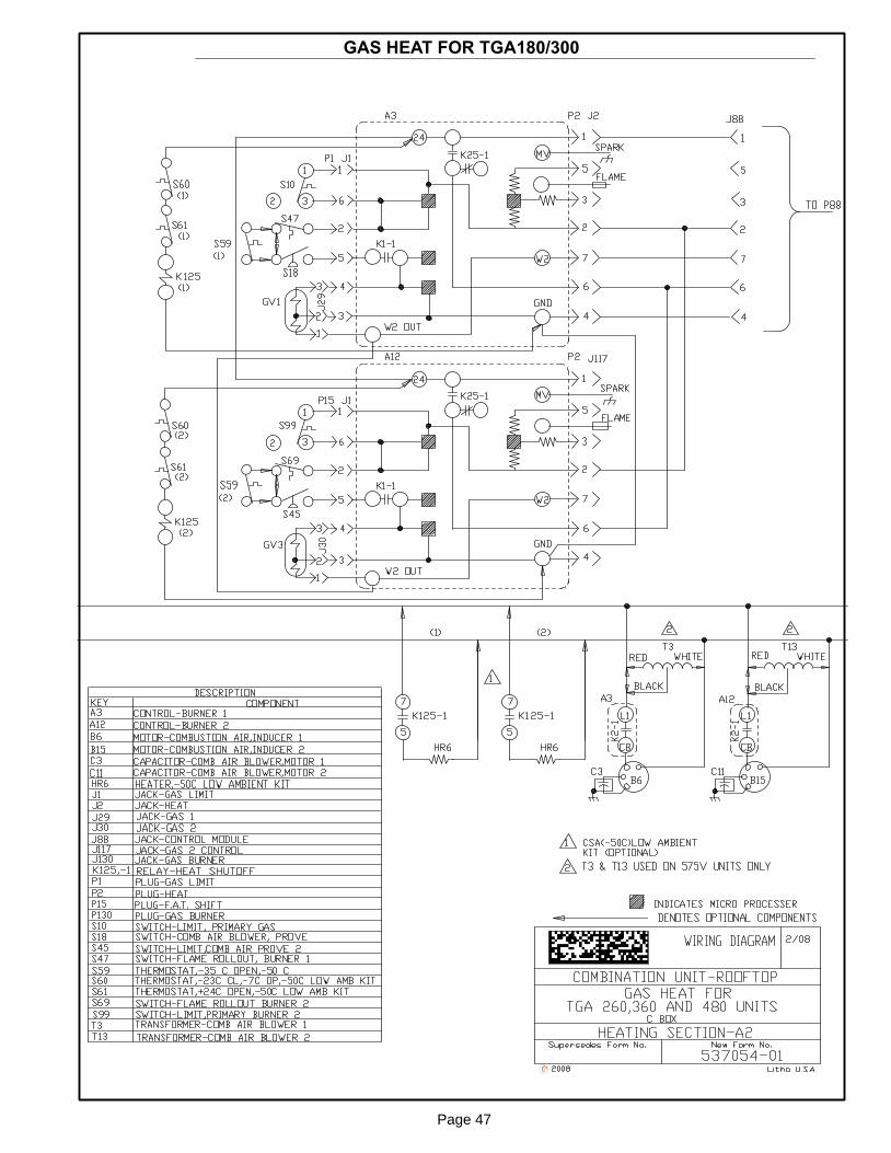
Page 47
GAS HEAT FOR TGA180/300

Page 48
GAS HEAT FOR TGA180/300 UNITS
First−Stage Heat:
1. The thermostat initiates W1 heating demand.
2. 24VAC is routed from TB1 on control module A45 to ignition control A3 (first heat
section) and A12 (second heat section) through P88. A3 proves N.C. primary limit
S10 and N.C. rollout switch S47. A12 proves N.C primary limit S99 and rollout
switch S69.
3. Combustion air inducer B6 and B15 are energized.
4. After the combustion air inducers B6 and B15 have reached full speed, the combus-
tion air proving switches S18 and S45 close.
5. After a 30 second delay A3 energizes the ignitor and LO terminal (low fire) of gas
valve GV1. A12 energizes the ignitor and LO terminal (low fire) of GV3.
Second−Stage Heat:
6. With first−stage heat operating, an additional heating demand from the thermostat
initiates W2.
7. A second−stage heating demand is received by A45 control module. The second
stage heat signal passes from A45 to A3 and A12.
8. A3 energizes HI terminal (high fire) of gas valve GV1 and A12 energizes HI terminal
(high fire) of gas valve GV3.
End of Second−Stage Heat:
9. Heating demand is satisfied. Terminal W2 (high fire) is de−energized.
10. Terminal HI of GV1 is de−energized by A3 and terminal HI of GV3 is de−energized by
A12..
End of First−Stage Heat:
11. Heating demand is satisfied. Terminal W1 (low fire) is de−energized.
12. Ignition A3 is de−energized by control module A45 in turn de−energizing terminal LO of
GV1. A12 is de−energized as well, de−energizing LO terminal on GV3.
Optional Low Ambient Kit:
(C.G.A. −50°C Low Ambient Kit)
13. Line voltage (or transformer T20 in 460V and 575V only) is routed through the low
ambient kit fuses F20 and N.C. low ambient kit thermostats S60 and S61,to energize
low ambient kit heater HR6.

Page 49
ELECTRONIC OR ELECTROMECHANICAL THERMOSTAT
POWER:
1. Terminal strip TB1 found on the main control module A45 energize thermostat components with 24VAC.
OPERATION:
2. The main control module A45 receives data from the electronic thermostat A2 (Y1, Y2, Y3, W1, W2, G, OCP)A45 energizes the appropriate components for heat or cool demand.

Page 50
�T" SERIES ECONOMIZER
SEQUENCE OF OPERATION
POWER:
1. Economizer control module A6 is energized through main module A45, P142 when contactor K3 is ener-
gized.
OPERATION:
2. Enthalpy sensor A7 and A62 (if differential enthalpy is used) communicates to the economizer control
module A6 when to power the damper motor B7.
3. Economizer control module A6 supplies B7 with 0 − 10 VDC to control the positioning of economizer.
4. The damper actuator provides 2 to 10 VDC position feedback.