Embed Size (px)
Citation preview
TG789vac v2
Setup and User Guide
Copyright
Copyright ©1999-2016 Technicolor. All rights reserved. Distribution and copying of this document, use and communication of its contents are not permitted without written authorization from Technicolor. The content of this document is furnished for informational use only, may be subject to change without notice, and should not be construed as a commitment by Technicolor. Technicolor assumes no responsibility or liability for any errors or inaccuracies that may appear in this document.Technicolor1-5 rue Jeanne d’Arc92130 Issy-les-MoulineauxFrancehttp://www.technicolor.com
Trademarks
The following trademarks may be used in this document:• AllSeen™, AllSeen Alliance™, the AllSeen Alliance logo, AllJoyn™, the AllJoyn logo and the Designed for AllSeen logo are trademarks
of the AllSeen Alliance, Inc.• AutoWAN sensing™ is a trademark of Technicolor.• Qeo™ is a trademark of Qeo LLC, a subsidiary of Technicolor.• Adobe®, the Adobe logo, Acrobat® and Adobe Reader® are trademarks or registered trademarks of Adobe Systems, Incorporated,
registered in the United States and/or other countries.• Apple® and Mac OS® are registered trademarks of Apple Computer, Incorporated, registered in the United States and other countries.• Bluetooth® word mark and logos are owned by the Bluetooth SIG, Inc.• CableLabs® and DOCSIS® are registered trademarks of CableLabs, Inc.• DECT™ is a trademark of ETSI.• DLNA® is a registered trademark, DLNA disc logo is a service mark, and DLNA Certified™ is a trademark of the Digital Living
Network Alliance. Digital Living Network Alliance is a service mark of the Digital Living Network Alliance.• Ethernet™ is a trademark of the Xerox Corporation.• EuroDOCSIS™, EuroPacketCable™ and PacketCable™ are trademarks of CableLabs, Inc.• HomePNA™ and HPNA™ are trademarks of HomePNA, Inc.• Linux™ is a trademark of Linus Torvalds.• Microsoft®, MS-DOS®, Windows®, Windows NT® and Windows Vista® are either registered trademarks or trademarks of the Micro-
soft Corporation in the United States and/or other countries.• MoCA® and the MoCA logo are registered trademarks of the Multimedia over Coax Alliance.• The N-Mark is a trademark or registered trademark of NFC Forum, Inc. in the United States and in other countries.• UNIX® is a registered trademark of UNIX System Laboratories, Incorporated.• UPnP™ is a certification mark of the UPnP Implementers Corporation.• Wi-Fi Alliance®, Wi-Fi®, WMM® and the Wi-Fi logo are registered trademarks of the Wi-Fi Alliance. Wi-Fi CERTIFIED™, Wi-Fi
ZONE™, Wi-Fi Protected Access™, Wi-Fi Multimedia™, Wi-Fi Protected Setup™, WPA™, WPA2™ and their respective logos are trade-marks of the Wi-Fi Alliance.
Other brands and product names may be trademarks or registered trademarks of their respective holders. All other logos, trademarks and service marks are the property of their respective owners, where marked or not.
Document Information
Status: v1.0 (April 2016)Reference: DMS3-CTC-25-282Short Title: Setup and User Guide TG789vac v2 R10.5.x
Contents
DMS3-
ContentsAbout this Setup and User Guide..................................................................................1
1 Getting started.......................................................................................................... 21.1 Features at a glance ...................................................................................................................................31.2 User scenarios ............................................................................................................................................ 41.3 Components ...............................................................................................................................................5
1.3.1 Power ............................................................................................................................................................................... 61.3.2 Local network connection ..............................................................................................................................................71.3.3 Broadband connection .................................................................................................................................................. 81.3.4 Voice connection ........................................................................................................................................................... 91.3.5 Buttons........................................................................................................................................................................... 101.3.6 Status LEDs ................................................................................................................................................................... 11
2 Setup ........................................................................................................................142.1 Connecting the TG789vac v2 to your service provider’s network..................................................... 15
2.1.1 Setting up your TG789vac v2 as DSL gateway.........................................................................................................162.1.2 Setting up your TG789vac v2 as local router ............................................................................................................18
2.2 Powering on the TG789vac v2 ............................................................................................................... 192.3 Connecting your network devices to the TG789vac v2..................................................................... 20
2.3.1 Setting up a wireless connection .................................................................................................................................212.3.2 Setting up a wired connection .................................................................................................................................... 22
2.4 Configure the TG789vac v2 ...................................................................................................................232.5 Setting up a mobile fall-back WAN connection ................................................................................. 24
2.5.1 Managing your mobile connection with the TG789vac v2 GUI............................................................................ 252.5.2 Inserting a mobile USB adapter.................................................................................................................................. 26
3 Configuration tools ..................................................................................................273.1 TG789vac v2 GUI................................................................................................................................... 28
3.1.1 Access............................................................................................................................................................................ 293.1.2 Components ................................................................................................................................................................. 303.1.3 Protecting access to the TG789vac v2.......................................................................................................................32
3.2 Backing up/restoring your configuration...............................................................................................333.3 Access from the Internet .........................................................................................................................34
4 Wireless networking.................................................................................................354.1 Connecting your wireless client via WPS ..............................................................................................364.2 Connecting your wireless client without WPS......................................................................................384.3 Connecting your wireless client by scanning a QR code ....................................................................394.4 Securing your wireless connection ........................................................................................................ 40
4.4.1 Configuring WPA encryption .....................................................................................................................................414.4.2 Configuring WPA-PSK encryption ........................................................................................................................... 42
5 Telephony................................................................................................................ 435.1 Setting up your telephone network....................................................................................................... 44
5.1.1 Configuring the TG789vac v2 VoIP service............................................................................................................. 455.2 Address book........................................................................................................................................... 47
iCTC-25-282 v1.0
Contents
DMS3-
5.3 Viewing call logs ...................................................................................................................................... 49
6 Saving energy .......................................................................................................... 506.1 Code of Conduct ..................................................................................................................................... 516.2 ECO manager ..........................................................................................................................................52
7 Sharing content ....................................................................................................... 547.1 The TG789vac v2 network file server................................................................................................... 567.2 The TG789vac v2 UPnP AV media server.......................................................................................... 59
7.2.1 Configuring the UPnP AV media server ..................................................................................................................607.2.2 Using the UPnP AV media server ..............................................................................................................................61
7.3 The TG789vac v2 FTP server ................................................................................................................637.4 Working with managed partitions ......................................................................................................... 657.5 Safely removing your USB storage device............................................................................................67
8 Network Services .................................................................................................... 688.1 UPnP......................................................................................................................................................... 69
8.1.1 Accessing your TG789vac v2 via UPnP.................................................................................................................... 708.1.2 Managing your Internet connection via UPnP .......................................................................................................... 718.1.3 Configuring UPnP on the TG789vac v2....................................................................................................................728.1.4 Installing UPnP on Windows XP.................................................................................................................................73
8.2 Assigning services (HTTP, FTP,...) to a computer .............................................................................758.3 Dynamic DNS ..........................................................................................................................................778.4 Network time server.................................................................................................................................78
9 Internet security ...................................................................................................... 809.1 Parental Control .......................................................................................................................................81
9.1.1 Configuring content-based filtering .......................................................................................................................... 839.1.2 Adding rules for address-based filtering ................................................................................................................... 84
9.2 Firewall...................................................................................................................................................... 869.3 Access Control ........................................................................................................................................ 889.4 Wireless Time Control ........................................................................................................................... 90
10 Support.....................................................................................................................9110.1 General TG789vac v2 troubleshooting................................................................................................ 9210.2 Ethernet connection troubleshooting ...................................................................................................9310.3 Wireless connection troubleshooting................................................................................................... 9410.4 Voice over IP troubleshooting .............................................................................................................. 9610.5 Content sharing troubleshooting...........................................................................................................9710.6 Reset to factory defaults ........................................................................................................................ 98
iiCTC-25-282 v1.0
1
About this Setup and User Guide
DMS3-CTC-25-282 v1.0
About this Setup and User Guide
In this Setup and User GuideThe goal of this Setup and User Guide is to show you:• Set up your TG789vac v2 and local network• Configure and use the main features of your TG789vac v2.For more advanced scenarios and features visit the documentation pages on www.technicolor.com.
Used Symbols
Typographical ConventionsFollowing typographical convention is used throughout this manual:• This sample text indicates a hyperlink to a website.
Example: For more information, visit us at www.technicolor.com.• This sample text indicates an internal link.
Example: If you want to know more about guide, see “About this Setup and User Guide” on page 1.• This sample text indicates an important content-related word.
Example: To enter the network, you must authenticate yourself.• This sample text indicates a GUI element (commands on menus and buttons, dialog box elements, file names, paths and
folders).Example: On the File menu, click Open to open a file.
The danger symbol indicates that there may be a possibility of physical injury.
The warning symbol indicates that there may be a possibility of equipment damage.
The caution symbol indicates that there may be a possibility of service interruption.
The note symbol indicates that the text provides additional information about a topic.

1 Getting started
DMS3-
1 Getting startedIntroduction
This chapter gives you a brief overview of the main features and components of the TG789vac v2. After this chapter we will start with the installation.
Do not connect any cables to the TG789vac v2 until instructed to do so.
2CTC-25-282 v1.0
1 Getting started
DMS3-
1.1 Features at a glanceIntroduction
This section provides a brief overview of the main features of your TG789vac v2.
IPv6 ReadyYour TG789vac v2 is IPv6 ready. Internet Protocol version 6 (IPv6) is the next generation of Internet technologies aiming to effectively support the ever-expanding Internet usage and functionality, and also to address security concerns that exist in an IPv4 environment.
Internet connection features• Broadband Internet access via the integrated DSL modem.
The first chapters describe how to connect your TG789vac v2 to the Internet.• Broadband Internet access via the Gigabit WAN port .
The first chapters describe how to connect your TG789vac v2 to the Internet.• (Fall-back) mobile Internet access via the optional mobile USB adaptor.
For more information, see “2.5 Setting up a mobile fall-back WAN connection” on page 24.• Internet security for your entire network.
For more information, see “9 Internet security” on page 80.• Useful network tools like UPnP, Dynamic DNS and many more.
For more information, see “8 Network Services” on page 68.
Local networking features• Wireless access for your local network devices via the integrated IEEE 802.11ac and IEEE 802.11n wireless access point.
For more information, see “4 Wireless networking” on page 35.• Wired access via Ethernet cable for your local network devices via the Ethernet interface.
For more information, see “2.3 Connecting your network devices to the TG789vac v2” on page 20.• An Integrated media server allowing you to share your media with media players and other network devices. For more
information, see “7 Sharing content” on page 54.
Telephony featuresThe TG789vac v2 offers Voice over IP (VoIP) connectivity for traditional phones and IP phones.For more information see “5 Telephony” on page 43
ECO labelTechnicolor’s ECO label guarantees you that the TG789vac v2 is able to reduce its power consumption to an absolute minimum. For more information, see “6 Saving energy” on page 50.
TG789vac v2 configuration tools• The TG789vac v2 GUI allows you to configure your TG789vac v2 via your web browser.
For more information, see “3.1 TG789vac v2 GUI” on page 28.
3CTC-25-282 v1.0
1 Getting started
DMS3-
1.2 User scenariosScenarios
Depending of the architecture of your home network, you can use the TG789vac v2 in either of the following scenarios:• DSL Gateway• Local Router
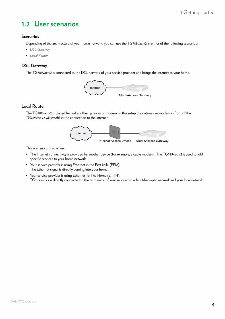
DSL GatewayThe TG789vac v2 is connected to the DSL network of your service provider and brings the Internet to your home.
Local RouterThe TG789vac v2 is placed behind another gateway or modem. In this setup the gateway or modem in front of the TG789vac v2 will establish the connection to the Internet:
This scenario is used when:• The Internet connectivity is provided by another device (for example, a cable modem). The TG789vac v2 is used to add
specific services to your home network.• Your service provider is using Ethernet in the First Mile (EFM).
The Ethernet signal is directly coming into your home.• Your service provider is using Ethernet To The Home (ETTH).
TG789vac v2 is directly connected to the terminator of your service provider’s fiber-optic network and your local network
Internet
MediaAccess Gateway
Internet
Internet Access Device MediaAccess Gateway
4CTC-25-282 v1.0
1 Getting started
DMS3-
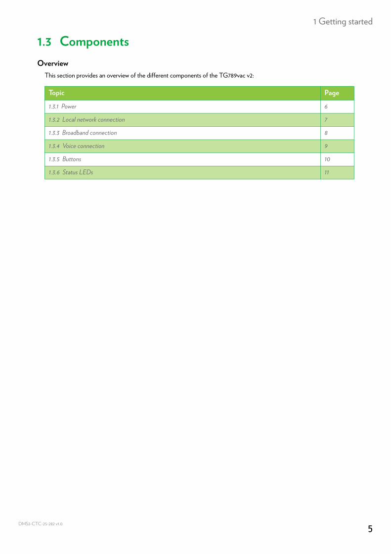
1.3 ComponentsOverview
This section provides an overview of the different components of the TG789vac v2:
Topic Page
1.3.1 Power 6
1.3.2 Local network connection 7
1.3.3 Broadband connection 8
1.3.4 Voice connection 9
1.3.5 Buttons 10
1.3.6 Status LEDs 11
5CTC-25-282 v1.0
1 Getting started
DMS3-
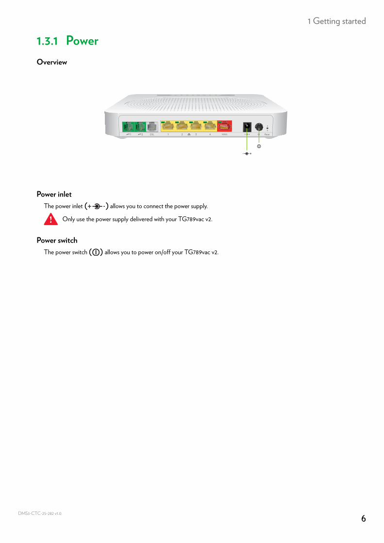
1.3.1 PowerOverview
Power inletThe power inlet ( ) allows you to connect the power supply.
Power switchThe power switch ( ) allows you to power on/off your TG789vac v2.
Only use the power supply delivered with your TG789vac v2.
6CTC-25-282 v1.0
1 Getting started
DMS3-
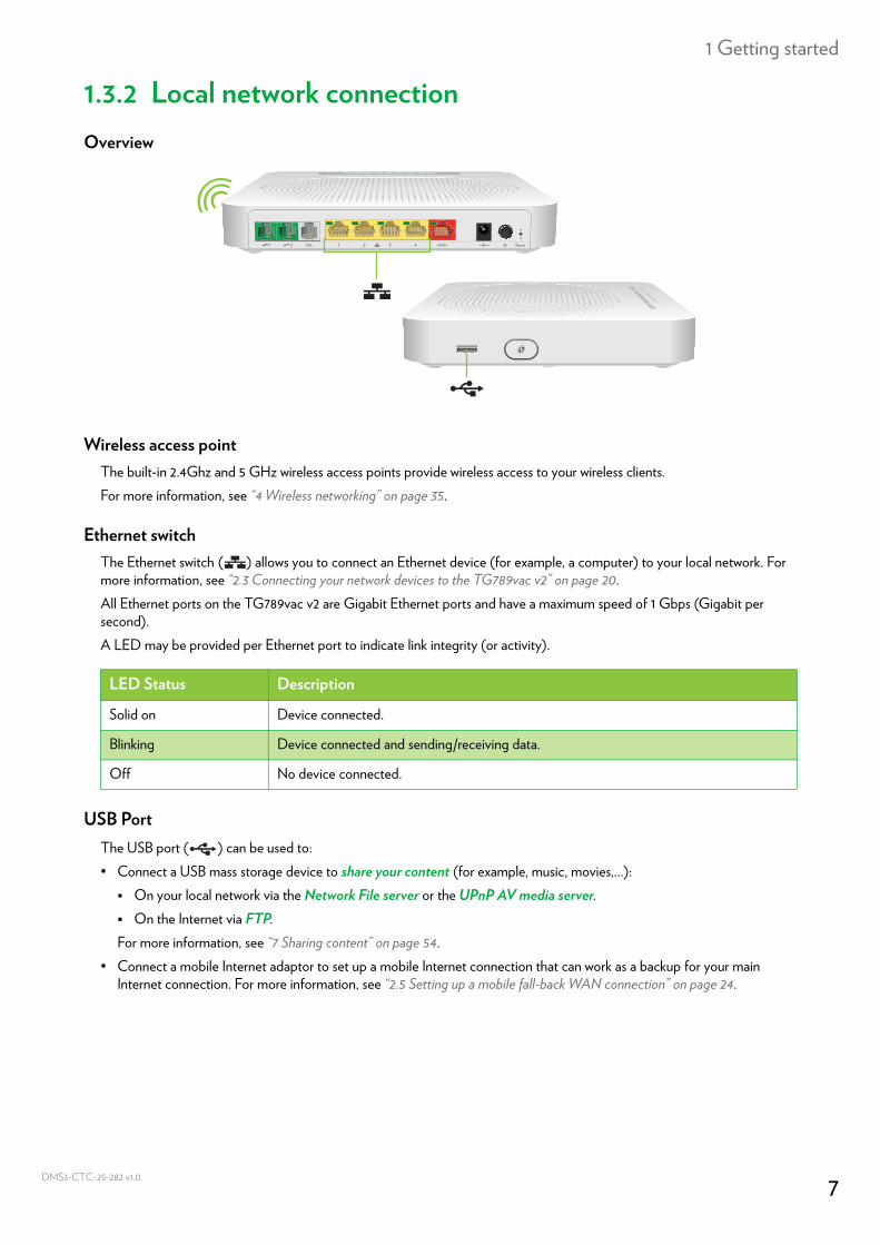
1.3.2 Local network connectionOverview
Wireless access pointThe built-in 2.4Ghz and 5 GHz wireless access points provide wireless access to your wireless clients.For more information, see “4 Wireless networking” on page 35.
Ethernet switchThe Ethernet switch ( ) allows you to connect an Ethernet device (for example, a computer) to your local network. For more information, see “2.3 Connecting your network devices to the TG789vac v2” on page 20.All Ethernet ports on the TG789vac v2 are Gigabit Ethernet ports and have a maximum speed of 1 Gbps (Gigabit per second).A LED may be provided per Ethernet port to indicate link integrity (or activity).
USB PortThe USB port ( ) can be used to:• Connect a USB mass storage device to share your content (for example, music, movies,...): On your local network via the Network File server or the UPnP AV media server. On the Internet via FTP.For more information, see “7 Sharing content” on page 54.
• Connect a mobile Internet adaptor to set up a mobile Internet connection that can work as a backup for your main Internet connection. For more information, see “2.5 Setting up a mobile fall-back WAN connection” on page 24.
LED Status Description
Solid on Device connected.
Blinking Device connected and sending/receiving data.
Off No device connected.
7CTC-25-282 v1.0
1 Getting started
DMS3-
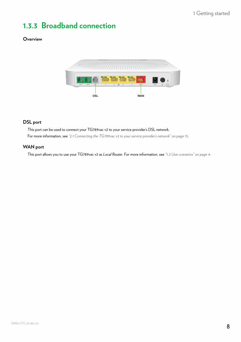
1.3.3 Broadband connectionOverview
DSL portThis port can be used to connect your TG789vac v2 to your service provider’s DSL network.For more information, see “2.1 Connecting the TG789vac v2 to your service provider’s network” on page 15.
WAN portThis port allows you to use your TG789vac v2 as Local Router. For more information, see “1.2 User scenarios” on page 4.
WANDSL
8CTC-25-282 v1.0
1 Getting started
DMS3-
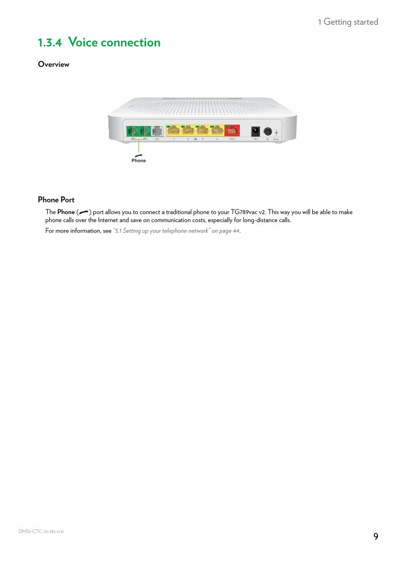
1.3.4 Voice connectionOverview
Phone PortThe Phone ( ) port allows you to connect a traditional phone to your TG789vac v2. This way you will be able to make phone calls over the Internet and save on communication costs, especially for long-distance calls.For more information, see “5.1 Setting up your telephone network” on page 44.
Phone
9CTC-25-282 v1.0
1 Getting started
DMS3-
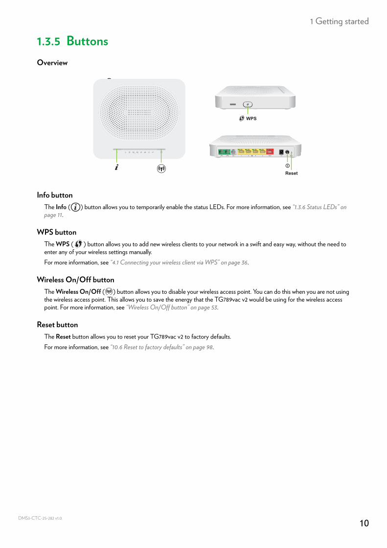
1.3.5 ButtonsOverview
Info buttonThe Info ( ) button allows you to temporarily enable the status LEDs. For more information, see “1.3.6 Status LEDs” on page 11.
WPS buttonThe WPS ( ) button allows you to add new wireless clients to your network in a swift and easy way, without the need to enter any of your wireless settings manually.For more information, see “4.1 Connecting your wireless client via WPS” on page 36.
Wireless On/Off buttonThe Wireless On/Off ( ) button allows you to disable your wireless access point. You can do this when you are not using the wireless access point. This allows you to save the energy that the TG789vac v2 would be using for the wireless access point. For more information, see “Wireless On/Off button” on page 53.
Reset buttonThe Reset button allows you to reset your TG789vac v2 to factory defaults.For more information, see “10.6 Reset to factory defaults” on page 98.
WPS
Reset
10CTC-25-282 v1.0
1 Getting started
DMS3-
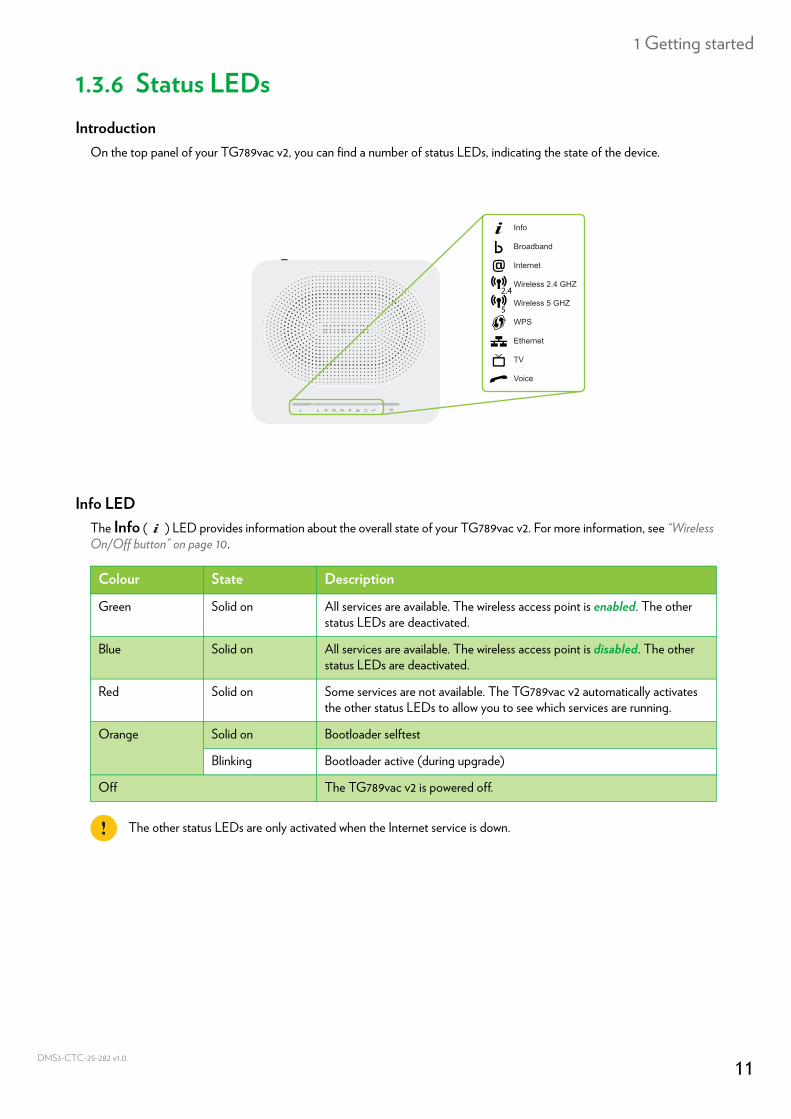
1.3.6 Status LEDsIntroduction
On the top panel of your TG789vac v2, you can find a number of status LEDs, indicating the state of the device.
Info LEDThe Info ( ) LED provides information about the overall state of your TG789vac v2. For more information, see “Wireless On/Off button” on page 10.
Info
Ethernet
Voice
Wireless 2.4 GHZ
Wireless 5 GHZ
Broadband
Internet
WPS
TV
Colour State Description
Green Solid on All services are available. The wireless access point is enabled. The other status LEDs are deactivated.
Blue Solid on All services are available. The wireless access point is disabled. The other status LEDs are deactivated.
Red Solid on Some services are not available. The TG789vac v2 automatically activates the other status LEDs to allow you to see which services are running.
Orange Solid on Bootloader selftest
Blinking Bootloader active (during upgrade)
Off The TG789vac v2 is powered off.
The other status LEDs are only activated when the Internet service is down.
11CTC-25-282 v1.0
1 Getting started
DMS3-
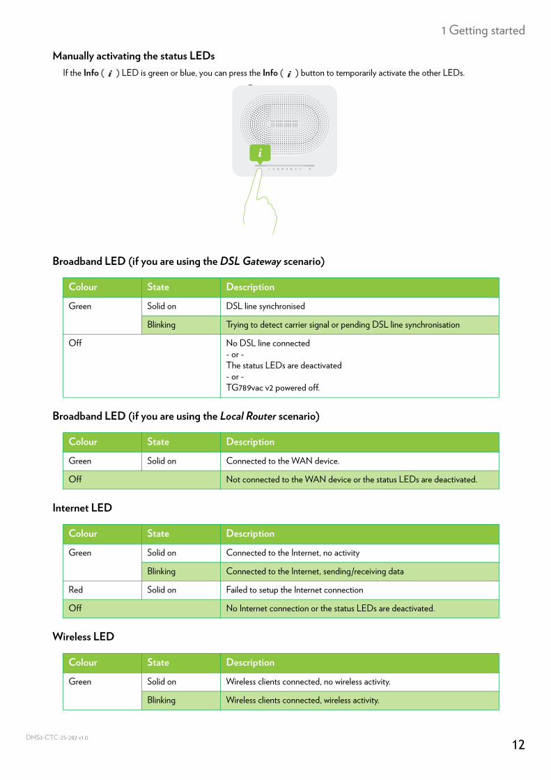
Manually activating the status LEDsIf the Info ( ) LED is green or blue, you can press the Info ( ) button to temporarily activate the other LEDs.
Broadband LED (if you are using the DSL Gateway scenario)
Broadband LED (if you are using the Local Router scenario)
Internet LED
Wireless LED
Colour State Description
Green Solid on DSL line synchronised
Blinking Trying to detect carrier signal or pending DSL line synchronisation
Off No DSL line connected- or - The status LEDs are deactivated- or -TG789vac v2 powered off.
Colour State Description
Green Solid on Connected to the WAN device.
Off Not connected to the WAN device or the status LEDs are deactivated.
Colour State Description
Green Solid on Connected to the Internet, no activity
Blinking Connected to the Internet, sending/receiving data
Red Solid on Failed to setup the Internet connection
Off No Internet connection or the status LEDs are deactivated.
Colour State Description
Green Solid on Wireless clients connected, no wireless activity.
Blinking Wireless clients connected, wireless activity.
12CTC-25-282 v1.0
1 Getting started
DMS3-
WPS LED
For more information about WPS, see “4.1 Connecting your wireless client via WPS” on page 36.
Ethernet LED
TV LED
Voice LED
Off No wireless clients connected or the status LEDs are deactivated.
Both the 2.4 GHz and 5 GHz access point have a dedicated Wireless LED.
Colour State Description
Green Solid On Client successfully registered via WPS.
Orange Blinking WPS registration ongoing.
Red Blinking Error occurred.
Colour State Description
Colour State Description
Green Solid on Network device connected to the Ethernet switch.
Blinking Network device connected to the Ethernet switch and sending/receiving data or the status LEDs are deactivated.
Off No Ethernet connection on your local network or the status LEDs are deactivated.
Colour State Description
Green Solid on Set-Top Box (STB) connected to the TG789vac v2.
Blinking Unknown STB connected to the TG789vac v2.
Off No STB connected to the TG789vac v2.
Colour State Description
Green Solid on Registered at your VoIP provider, no activity.
Blinking Registered at your VoIP provider, activity.
Off Not registered to your VoIP provider or the status LEDs are deactivated.
13CTC-25-282 v1.0
2 Setup
DMS3-
2 SetupIntroduction
This chapter will help you to setup your TG789vac v2.
DSL service requirementsThis section is only applicable if you are using your TG789vac v2 as DSL gateway. For more information, see “1.2 User scenarios” on page 4.Make sure that:• Your service provider activated the DSL service on your telephone line by your service provider.• You have the installation information (for example, user name, password, service profile,...) provided by your service
provider at hand.
Local connection requirementsWireless connectionIf you want to connect your computer using a wireless connection, your computer must be equipped with a Wi-Fi certified wireless client adapter.Wired connectionIf you want to connect a computer using a wired connection, your computer must be equipped with an Ethernet Network Interface Card (NIC).
Setting up your networkProceed as follows:1 Connect the TG789vac v2 to your service provider’s network.
For more information, see “2.1 Connecting the TG789vac v2 to your service provider’s network” on page 15.2 Power on the TG789vac v2.
For more information, see “2.2 Powering on the TG789vac v2” on page 19.3 Connect your network devices (for example, a computer) to the TG789vac v2.
For more information, see “2.3 Connecting your network devices to the TG789vac v2” on page 20.4 Configure the TG789vac v2.
For more information, see “2.4 Configure the TG789vac v2” on page 23.5 Connect your phones.
For more information, see “5 Telephony” on page 43.6 Share your content or media on your local network, continue with “7 Sharing content” on page 54.7 If you purchased a mobile USB adapter, setup the mobile backup connection.
For more information, see “2.5 Setting up a mobile fall-back WAN connection” on page 24.8 Once you successfully installed the TG789vac v2, it is recommend to backup your configuration. This allows you to return
to this configuration when needed (for example, after misconfiguration). For more information, see “3.2 Backing up/restoring your configuration” on page 33.
If your service provider included a setup CD/DVD in your box, please follow the instructions from that setup CD/DVD instead.
14CTC-25-282 v1.0
2 Setup
DMS3-
2.1 Connecting the TG789vac v2 to your service provider’s network
IntroductionThis section helps you to connect the TG789vac v2 to your service provider’s network.
Identifying your setupIf you are using the TG789vac v2 as:• DSL Gateway, continue with “2.1.1 Setting up your TG789vac v2 as DSL gateway” on page 16.• Local Router , continue with “2.1.2 Setting up your TG789vac v2 as local router” on page 18.For more information, see “1.2 User scenarios” on page 4, you can use your TG789vac v2 in either of the following scenarios
15CTC-25-282 v1.0
2 Setup
DMS3-
2.1.1 Setting up your TG789vac v2 as DSL gatewaySignal arriving at your home
The Line signal that arrives at your home consists the following components:• A Phone signal carrying the traffic for telephony.
• A DSL signal carrying the Internet traffic.DSL Gateways have a built-in solution to remove the Phone component. No additional devices are needed, you can connect them directly to the Line.Telephones do not have this capability, so here you have to use a filter or splitter to remove the DSL signal.
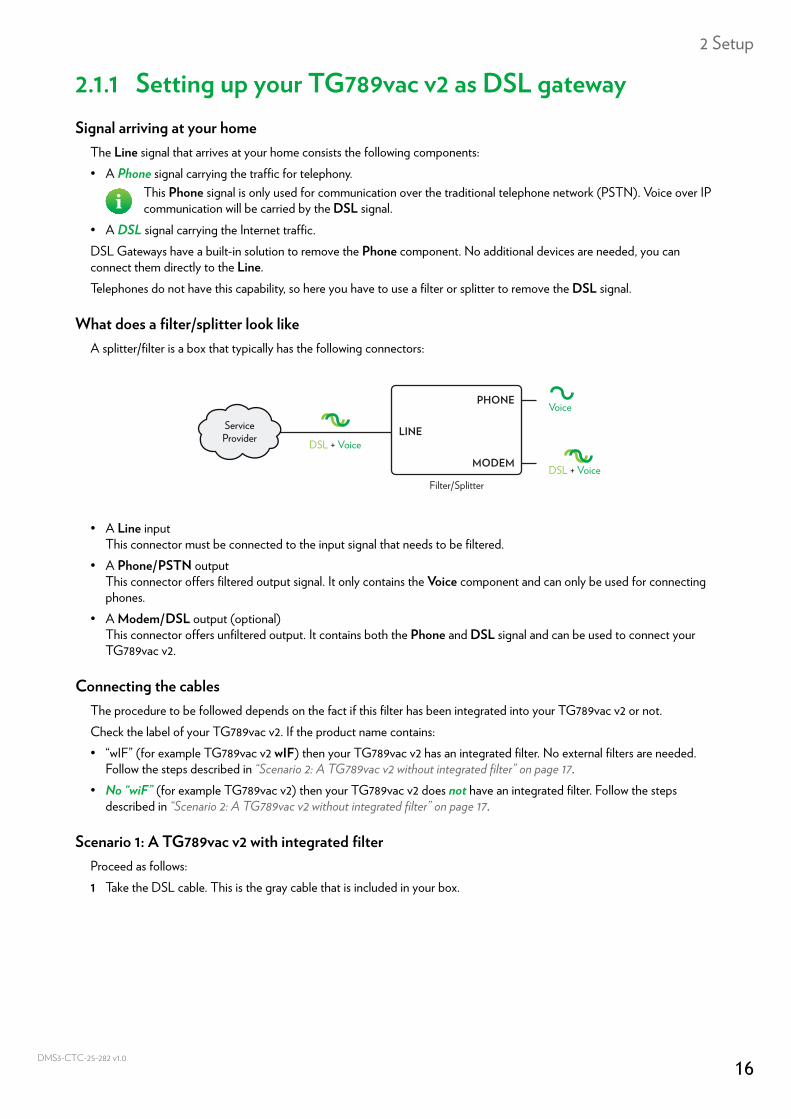
What does a filter/splitter look likeA splitter/filter is a box that typically has the following connectors:
• A Line inputThis connector must be connected to the input signal that needs to be filtered.
• A Phone/PSTN outputThis connector offers filtered output signal. It only contains the Voice component and can only be used for connecting phones.
• A Modem/DSL output (optional)This connector offers unfiltered output. It contains both the Phone and DSL signal and can be used to connect your TG789vac v2.
Connecting the cablesThe procedure to be followed depends on the fact if this filter has been integrated into your TG789vac v2 or not.Check the label of your TG789vac v2. If the product name contains:• “wIF” (for example TG789vac v2 wIF) then your TG789vac v2 has an integrated filter. No external filters are needed.
Follow the steps described in “Scenario 2: A TG789vac v2 without integrated filter” on page 17.• No “wiF” (for example TG789vac v2) then your TG789vac v2 does not have an integrated filter. Follow the steps
described in “Scenario 2: A TG789vac v2 without integrated filter” on page 17.
Scenario 1: A TG789vac v2 with integrated filterProceed as follows:1 Take the DSL cable. This is the gray cable that is included in your box.
This Phone signal is only used for communication over the traditional telephone network (PSTN). Voice over IP communication will be carried by the DSL signal.
DSL + Voice
Voice
DSL + Voice
ServiceProvider
Filter/Splitter
LINE
PHONE
MODEM
16CTC-25-282 v1.0
2 Setup
DMS3-
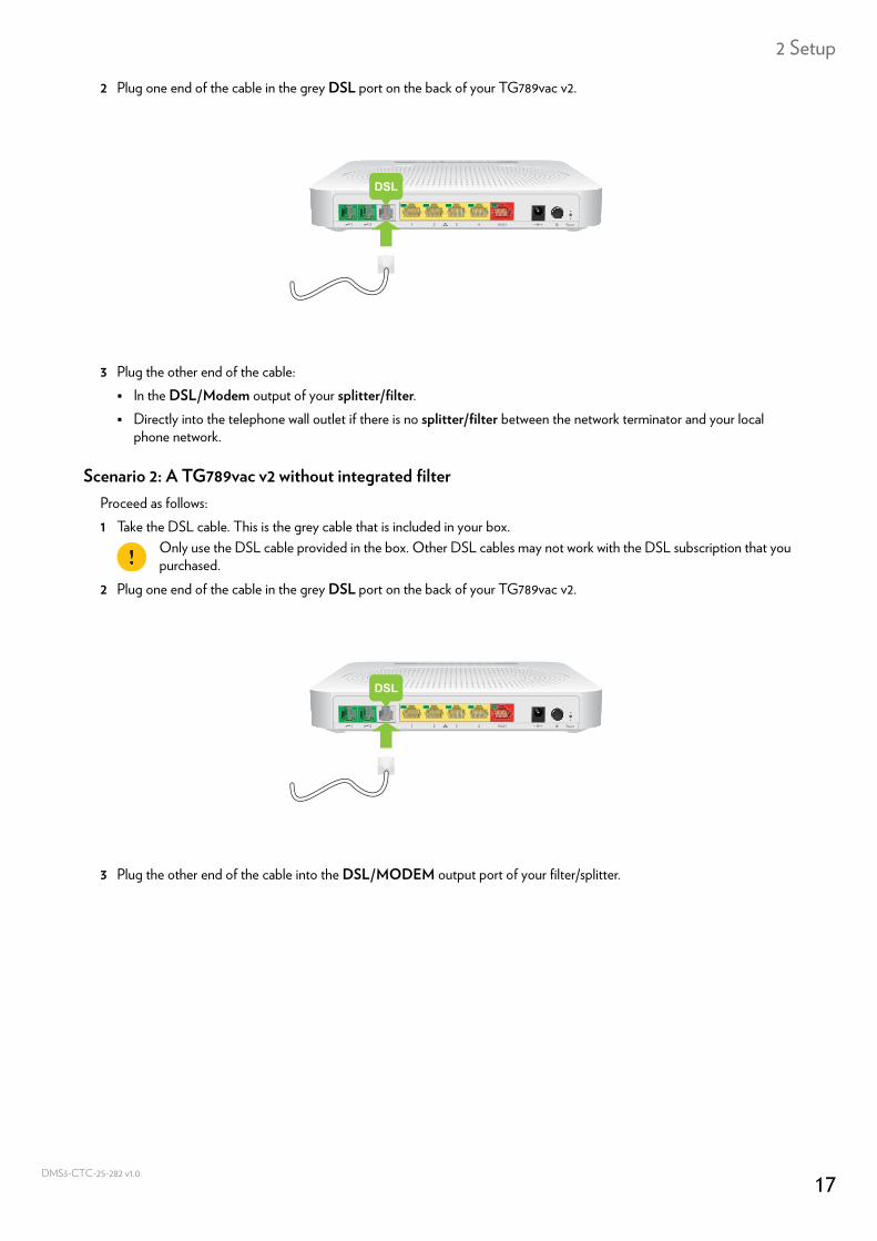
2 Plug one end of the cable in the grey DSL port on the back of your TG789vac v2.
3 Plug the other end of the cable: In the DSL/Modem output of your splitter/filter. Directly into the telephone wall outlet if there is no splitter/filter between the network terminator and your local
phone network.
Scenario 2: A TG789vac v2 without integrated filterProceed as follows:1 Take the DSL cable. This is the grey cable that is included in your box.
2 Plug one end of the cable in the grey DSL port on the back of your TG789vac v2.
3 Plug the other end of the cable into the DSL/MODEM output port of your filter/splitter.
DSL
Only use the DSL cable provided in the box. Other DSL cables may not work with the DSL subscription that you purchased.
DSL
17CTC-25-282 v1.0
2 Setup
DMS3-
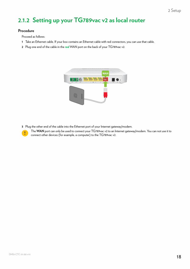
2.1.2 Setting up your TG789vac v2 as local routerProcedure
Proceed as follows:1 Take an Ethernet cable. If your box contains an Ethernet cable with red connectors, you can use that cable.2 Plug one end of the cable in the red WAN port on the back of your TG789vac v2.
3 Plug the other end of the cable into the Ethernet port of your Internet gateway/modem.The WAN port can only be used to connect your TG789vac v2 to an Internet gateway/modem. You can not use it to connect other devices (for example, a computer) to the TG789vac v2.
WAN
18CTC-25-282 v1.0
2 Setup
DMS3-
2.2 Powering on the TG789vac v2Procedure
Proceed as follows:1 Connect the power cord to the power port of the TG789vac v2.2 Plug the other end of the power cord into an electrical outlet.3 Press the power button to turn on the TG789vac v2.4 Wait at least two minutes to allow the TG789vac v2 to complete the start up phase.
19CTC-25-282 v1.0
2 Setup
DMS3-
2.3 Connecting your network devices to the TG789vac v2Choose your connection method
To connect your device via:• A wireless connection, continue with “2.3.1 Setting up a wireless connection” on page 21.• A wired connection using an Ethernet cable, continue with “2.3.2 Setting up a wired connection” on page 22.
20CTC-25-282 v1.0
2 Setup
DMS3-
2.3.1 Setting up a wireless connectionThe TG789vac v2 access points
Your TG789vac v2 is equipped with two wireless access points:• The 5 GHz wireless access point offers superior transfer rates, is less sensitive to interference and allows you to connect
IEEE802.11ac/n/a wireless clients.• The 2.4 GHz wireless access point allows you to connect IEEE802.11n/g/b wireless clients. Use this access point for
wireless clients that don’t support 5 GHz.
RequirementsYour network device must be equipped with a Wi-Fi certified wireless client.
Connection speedWhen setting up your wireless network, keep in mind that the following factors may have a negative impact on your wireless connection speed:• Obstacles (walls, ceilings,...) between the wireless client and the access point.• Distance between the wireless client and the access point.If you have problems with your wireless performance, see “Poor Wireless Connectivity or Range” on page 94.
To set up a wireless connectionsFor more information on how to setup a wireless connection between your network device and your TG789vac v2, see “4 Wireless networking” on page 35.
21CTC-25-282 v1.0
2 Setup
DMS3-
2.3.2 Setting up a wired connectionRequirements
• Both your network device (for example, a computer, a gaming console,...) and TG789vac v2 must have a free Ethernet port.
• Your network device must be configured to obtain an IP address automatically. This is the default setting.
Connection speedAll Ethernet ports on the TG789vac v2 are Gigabit Ethernet ports and have a maximum speed of 1 Gbps (Gigabit per second).
Ethernet cableIn your package, you will find a cable with yellow connectors. This is the Ethernet cable.When using other cables than the ones provided in your box, make sure to use the correct type of cable:• Category 5 Enhanced (CAT5E) cables help to prevent cross-talk and are used for 10/100Mb/1000Mb(Gigabit Ethernet)• Category 6 (CAT6) cables are similar to Cat 5E cables but have larger gauge wires and are used for 10/100/1000Mb
(Gigabit Ethernet). This cable is better than CAT5E for Gigabit Ethernet.
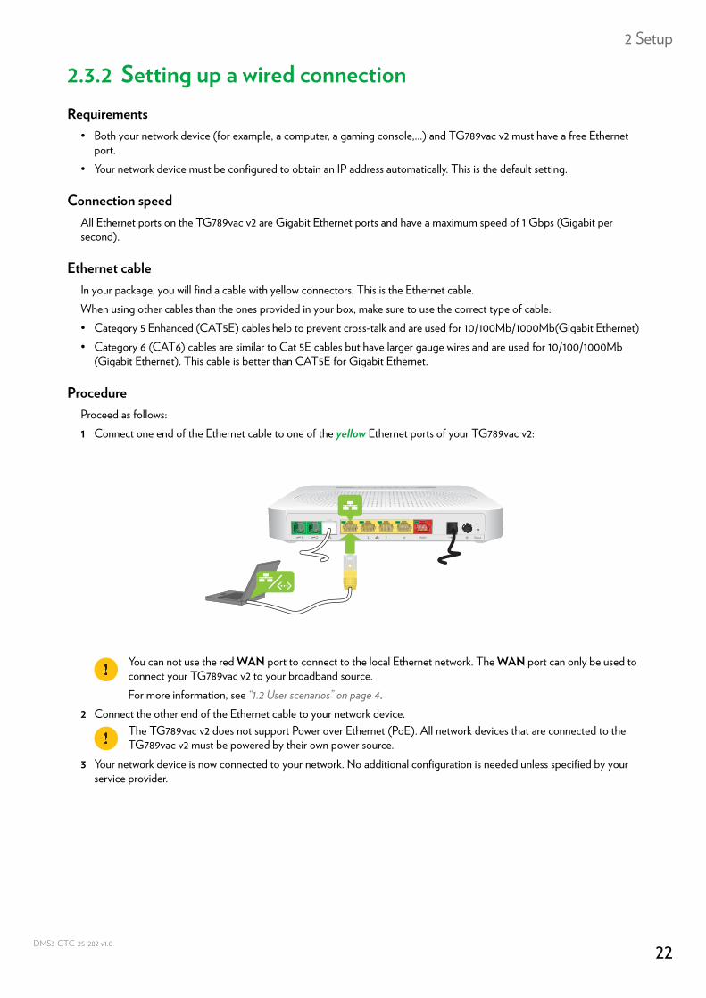
ProcedureProceed as follows:1 Connect one end of the Ethernet cable to one of the yellow Ethernet ports of your TG789vac v2:
2 Connect the other end of the Ethernet cable to your network device.
3 Your network device is now connected to your network. No additional configuration is needed unless specified by your service provider.
You can not use the red WAN port to connect to the local Ethernet network. The WAN port can only be used to connect your TG789vac v2 to your broadband source.For more information, see “1.2 User scenarios” on page 4.
The TG789vac v2 does not support Power over Ethernet (PoE). All network devices that are connected to the TG789vac v2 must be powered by their own power source.
22CTC-25-282 v1.0
2 Setup
DMS3-
2.4 Configure the TG789vac v2Introduction
If your service provider did not preconfigure your TG789vac v2, you may have to configure the TG789vac v2 via its Graphical User Interface (GUI).
RequirementsJavaScript must be enabled on your web browser (this is the default setting). For more information, consult the help of your web browser.
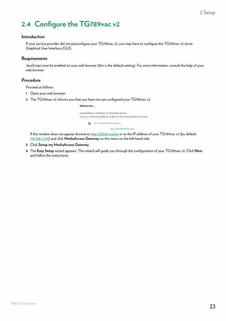
ProcedureProceed as follows:1 Open your web browser.2 The TG789vac v2 informs you that you have not yet configured your TG789vac v2.
If this window does not appear, browse to http://dsldevice.lan or to the IP address of your TG789vac v2 (by default: 192.168.1.254) and click MediaAccess Gateway on the menu on the left-hand side.
3 Click Setup my MediaAccess Gateway.4 The Easy Setup wizard appears. This wizard will guide you through the configuration of your TG789vac v2. Click Next
and follow the instructions.
23CTC-25-282 v1.0
2 Setup
DMS3-
2.5 Setting up a mobile fall-back WAN connectionMobile fall-back
The TG789vac v2 allows you to use a mobile Internet connection (for example, 3G) as fall-back connection for your Internet access. This means that the TG789vac v2 will automatically switch to the mobile Internet connection when your normal Internet connection is down.The TG789vac v2 will automatically switch back to the normal Internet connection as soon as it becomes available again.
What do I need?To set up mobile fall-back connection, you need:• A mobile USB adapter
• A registered Security Identity Module (SIM) card.
Configure the mobile interface as WAN connectionProceed as follows:1 Configure your mobile connection.
For more information, see “2.5.1 Managing your mobile connection with the TG789vac v2 GUI” on page 25.2 Insert your mobile USB adapter.
For more information, see “2.5.2 Inserting a mobile USB adapter” on page 26.3 Now your mobile connection is up and ready to use.
ResultTG789vac v2 will automatically enable your mobile Internet connection when both of the following conditions are met:• The main Internet connection has been unavailable for at least 60 seconds.• The TG789vac v2 received a request to access the Internet (for example, when browsing to an Internet website).The TG789vac v2 will automatically disable the mobile Internet connection in either of the following cases:• The main Internet connection is available again. In this case the TG789vac v2 switches back to the main Internet
connection.• No Internet traffic has been detected during the last 10 seconds. For example, you finished surfing the Internet.
Only use the mobile USB adapters provided by your service provider.
If you need to remove your mobile USB adapter, make sure the TG789vac v2 is powered off first.
24CTC-25-282 v1.0
2 Setup
DMS3-
2.5.1 Managing your mobile connection with the TG789vac v2 GUI
IntroductionYou can view and manage the parameters of your mobile Internet connection via the TG789vac v2 GUI.
ProcedureTo manage your mobile Internet connection via the TG789vac v2 GUI:1 Browse to the TG789vac v2 GUI.
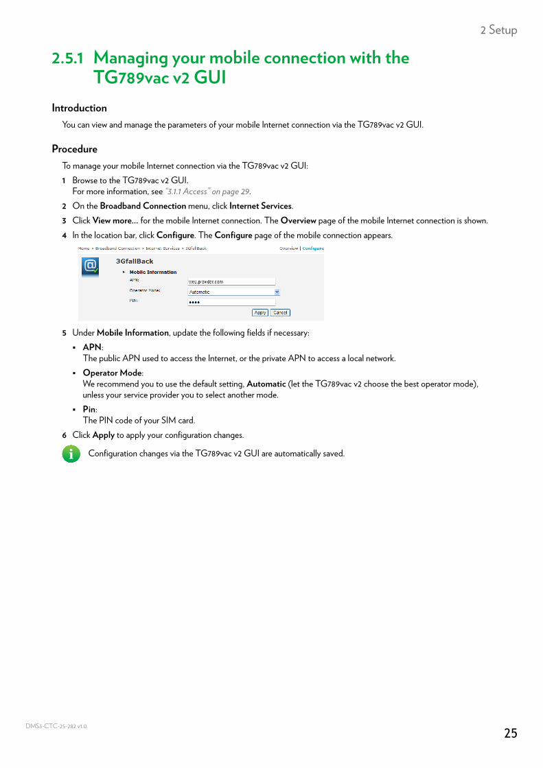
For more information, see “3.1.1 Access” on page 29.2 On the Broadband Connection menu, click Internet Services.3 Click View more... for the mobile Internet connection. The Overview page of the mobile Internet connection is shown. 4 In the location bar, click Configure. The Configure page of the mobile connection appears.
5 Under Mobile Information, update the following fields if necessary: APN:
The public APN used to access the Internet, or the private APN to access a local network. Operator Mode:
We recommend you to use the default setting, Automatic (let the TG789vac v2 choose the best operator mode), unless your service provider you to select another mode.
Pin:The PIN code of your SIM card.
6 Click Apply to apply your configuration changes.
Configuration changes via the TG789vac v2 GUI are automatically saved.
25CTC-25-282 v1.0
2 Setup
DMS3-
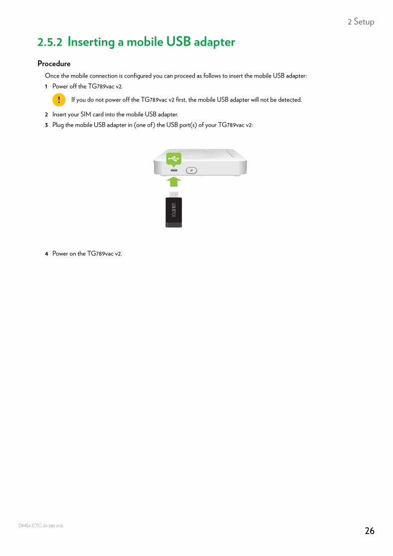
2.5.2 Inserting a mobile USB adapterProcedure
Once the mobile connection is configured you can proceed as follows to insert the mobile USB adapter:1 Power off the TG789vac v2.
2 Insert your SIM card into the mobile USB adapter.3 Plug the mobile USB adapter in (one of) the USB port(s) of your TG789vac v2:
4 Power on the TG789vac v2.
If you do not power off the TG789vac v2 first, the mobile USB adapter will not be detected.
26CTC-25-282 v1.0
3 Configuration tools
DMS3-
3 Configuration toolsConfiguration Tools
You can use the following tools to configure your TG789vac v2:• The TG789vac v2 GUI allows you to configure your TG789vac v2 via your web browser.
For more information, see “3.1 TG789vac v2 GUI” on page 28.
27CTC-25-282 v1.0
3 Configuration tools
DMS3-
3.1 TG789vac v2 GUIIntroduction
The TG789vac v2 Graphical User Interface (GUI) allows you to configure your TG789vac v2 using your web browser.
RequirementsJavaScript must be enabled on your browser (this is the default setting). For more information, consult the help of your web browser.
28CTC-25-282 v1.0
3 Configuration tools
DMS3-
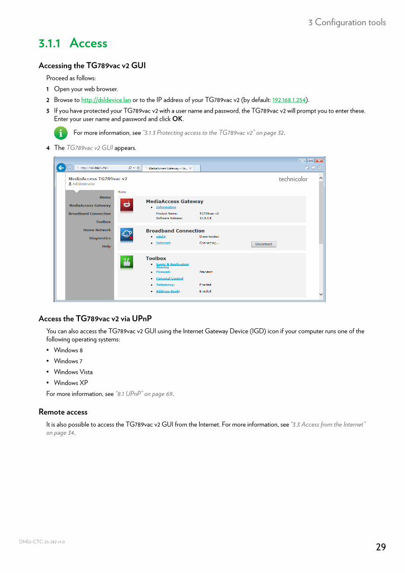
3.1.1 AccessAccessing the TG789vac v2 GUI
Proceed as follows:1 Open your web browser.2 Browse to http://dsldevice.lan or to the IP address of your TG789vac v2 (by default: 192.168.1.254).3 If you have protected your TG789vac v2 with a user name and password, the TG789vac v2 will prompt you to enter these.
Enter your user name and password and click OK.
4 The TG789vac v2 GUI appears.
Access the TG789vac v2 via UPnPYou can also access the TG789vac v2 GUI using the Internet Gateway Device (IGD) icon if your computer runs one of the following operating systems:• Windows 8• Windows 7• Windows Vista• Windows XPFor more information, see “8.1 UPnP” on page 69.
Remote accessIt is also possible to access the TG789vac v2 GUI from the Internet. For more information, see “3.3 Access from the Internet” on page 34.
For more information, see “3.1.3 Protecting access to the TG789vac v2” on page 32.
29CTC-25-282 v1.0
3 Configuration tools
DMS3-
3.1.2 ComponentsOverview
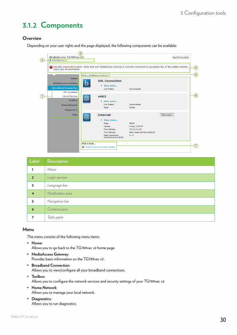
Depending on your user rights and the page displayed, the following components can be available:
MenuThe menu consists of the following menu items:• Home:
Allows you to go back to the TG789vac v2 home page.• MediaAccess Gateway:
Provides basic information on the TG789vac v2.• Broadband Connection:
Allows you to view/configure all your broadband connections.• Toolbox:
Allows you to configure the network services and security settings of your TG789vac v2.• Home Network:
Allows you to manage your local network.• Diagnostics:
Allows you to run diagnostics.
Label Description
1 Menu
2 Login section
3 Language bar
4 Notification area
5 Navigation bar
6 Content pane
7 Tasks pane
4
5
1 6
7
2
3
30CTC-25-282 v1.0
3 Configuration tools
DMS3-
• Help:Allows you to view context-related help information.
Each of these items may contain a number of sub-menu items.
Login sectionIn the login section you can see the current user name.By clicking the user name, you can:• Change your password.• Switch to another user.
Language barIf more than one GUI language is available, a language bar is showed. This language bar allows you to change the language of the TG789vac v2 GUI.
Notification areaThe notification area displays:• Error messages, indicated by a red traffic light.• Warning messages, indicated by an orange traffic light.• Information messages, indicated by a green traffic light.
Navigation barThe navigation bar displays your current position in the TG789vac v2 GUI.Some page are available in different configuration levels. These pages have additional links (for example, Overview, Details, Configure) in the right part of the navigation bar that allow you to switch between the configuration levels.
Content paneThe content pane displays the information and configurable items of the selected item.
Tasks paneTo allow a quick configuration of your TG789vac v2, some pages may offer you a number of related tasks in the Pick a task list. These tasks will guide you to the page where you can perform the selected task.
If none of these events occur, the notification area is not shown.
31CTC-25-282 v1.0
3 Configuration tools
DMS3-
3.1.3 Protecting access to the TG789vac v2Introduction
To prevent that every user on your local network can access the TG789vac v2, the TG789vac v2 is secured with a user name and password.
Protected itemsThe user name and password is used to secure access to:• The TG789vac v2 GUI.• The embedded FTP Server.
for more information, see “7.3 The TG789vac v2 FTP server” on page 63.
Default user nameThe default user name is Administrator.
Default passwordThe default password is either blank or the ACCESS KEY printed on the label of your TG789vac v2. This depends on the settings chosen by your Service Provider.
How to change your passwordProceed as follows:1 On the Toolbox menu, click User Management.2 In the Pick a task list, click Change my password.3 Enter your new password and click OK.4 Your new password is now active. The next time that you log on to the TG789vac v2 GUI you will have to enter this
password.
It is recommended to change the default password settings.Choose a password that your can easily remember or write it down. If you forget your password the only option is to reset your TG789vac v2. For more information, see “10.6 Reset to factory defaults” on page 98.
This password will also be used by the network file server and FTP server.For more information about the network file server and FTP server, see “7 Sharing content” on page 54
32CTC-25-282 v1.0
3 Configuration tools
DMS3-
3.2 Backing up/restoring your configurationIntroduction
Once you have configured your TG789vac v2 to your needs, it is recommended to backup your configuration for later use. This way you can always return to your working configuration in case of problems.
Backing up your configurationProceed as follows:1 Browse to the TG789vac v2 GUI.
For more information, see “Accessing the TG789vac v2 GUI” on page 29.2 On the MediaAccess Gateway menu, click Configuration.3 In the Pick a task list, click Save or Restore Configuration.4 Under Backup current configuration, click Backup Configuration Now.5 The TG789vac v2 prompts you to save your backup file.
6 Save your file to a location of your choice.
Restoring your configurationProceed as follows:1 Browse to the TG789vac v2 GUI.
For more information, see “Accessing the TG789vac v2 GUI” on page 29.2 On the MediaAccess Gateway menu, click Configuration.3 In the Pick a task list, click Save or Restore Configuration.4 Under Restore saved configuration, click Browse and open your backup file.
5 The TG789vac v2 restores your configuration.6 If needed, the TG789vac v2 will restart.
Do not change the file extension.
Do not edit the backup files as this may result in corrupt files making them worthless as configuration backup.
Backup files usually have .ini as extension.
33CTC-25-282 v1.0
3 Configuration tools
DMS3-
3.3 Access from the InternetModes
To access your TG789vac v2 GUI from the Internet, you can choose between two modes:• Permanent Mode (Remote Access):
The remote session ends when you disable remote assistance or after restarting your TG789vac v2.• Temporary Mode (Remote Assistance):
The remote session ends when you disable remote assistance, after restarting your TG789vac v2 or after 20 minutes of inactivity.
To enable Remote Assistance / Remote Access
To enable remote assistance/access:1 Browse to the TG789vac v2 GUI.
For more information, see “Accessing the TG789vac v2 GUI” on page 29.2 Complete and check the following parameters: Mode:
Select the mode that you want to use. URL:
Contains the URL that must be used to access the TG789vac v2 from the Internet. User name:
The user name needed to access your TG789vac v2 remotely. Use Random password and Password:
• Click the Use Random password check box if you want the TG789vac v2 to generate a random password. The password will appear in the Password box as soon as you enable remote assistance.
• Clear the Use Random password check box if you want to choose the password yourself. Enter the password of your choice in the Password box.
3 Click Enable Remote Access or Enable Remote Assistance.
Accessing your TG789vac v2 from the InternetProceed as follows:1 Open your web browser.2 Type the URL that was listed in the URL field on the Remote Assistance page (for example https://141.11.249.150:51003).
3 Enter the user name and password that you specified on the Remote Assistance page.4 The TG789vac v2 GUI appears.It is now possible for a remote user to access your TG789vac v2 via the specified URL using the provided user name and password.
Enabling remote assistance is only possible when you are connected to the Internet.
You can replace the IP address in this URL by the dynamic DNS host name if you enabled and configured Dynamic DNS. For more information, see “8.3 Dynamic DNS” on page 77.Example: https://141.11.249.150:51003 can be replaced by https://mygateway.dyndns.org:51003.
34CTC-25-282 v1.0
4 Wireless networking
DMS3-
4 Wireless networkingIntroduction
This section will help you set up your wireless network for your wireless devices.
What you need to set up a wireless networkTo set up a wireless network, you need the following components:• A Wireless access point (already integrated into your TG789vac v2)• A Wireless client the device that you want to connect (for example, a computer, smartphone, network printer,...)
Wireless access pointThe wireless access point:• Connects your wireless devices to the TG789vac v2 (and its services).• Allows you to secure the data sent over wireless connection.Your TG789vac v2 is equipped with two wireless access points:• The 5 GHz wireless access point offers superior transfer rates, is less sensitive to interference and allows you to connect
IEEE802.11ac/n/a wireless clients.• The 2.4 GHz wireless access point allows you to connect IEEE802.11n/g/b wireless clients. Use this access point for
wireless clients that don’t support 5 GHz.
Wireless clientThe wireless client allows you to connect a device, typically a computer, to a wireless access point. Both built-in and external (for example via USB) clients are available.
Check the documentation of your computer if you are not sure if your computer is equipped with a wireless client.
Configuring your wireless clientsFor more information on how to establish a wireless connection to the TG789vac v2, see: • “4.1 Connecting your wireless client via WPS” on page 36• “4.2 Connecting your wireless client without WPS” on page 38• “4.3 Connecting your wireless client by scanning a QR code” on page 39
Secure your wireless connection!When using an unsecured connection, everyone who is within the range of your TG789vac v2 can access your network. If not:• People may use your connection to access the Internet.• Hackers may use your connection to commit computer crimes.You can easily prevent this by securing your wireless access point. For more information, see “4.4 Securing your wireless connection” on page 40.
Nowadays devices like media players and smartphones have a built-in wireless client. Check the documentation of your device for more information.
35CTC-25-282 v1.0
4 Wireless networking
DMS3-
4.1 Connecting your wireless client via WPSWPS
Wi-Fi Protected Setup (WPS) allows you to add new wireless clients to your local network in a swift and easy way, without the need to enter any of your wireless settings (network name, wireless key, encryption type).
Requirements• Your wireless client must support WPS. Check the documentation of your wireless client for this.
• Your TG789vac v2 must use WPA(2)-PSK encryption (default encryption) or no encryption. WPS with WEP encryption is not possible.
WPS MethodsThe following WPS methods are supported by your TG789vac v2:• Push Button Configuration (PBC):
You have to put both your wireless client and the TG789vac v2’s wireless access point in registration mode. See “Procedure for WPS PBC” on page 36.
• PIN code entry:You have to enter a PIN code on the configuration utility of your wireless client. See “Procedure for WPS PIN code entry” on page 37.
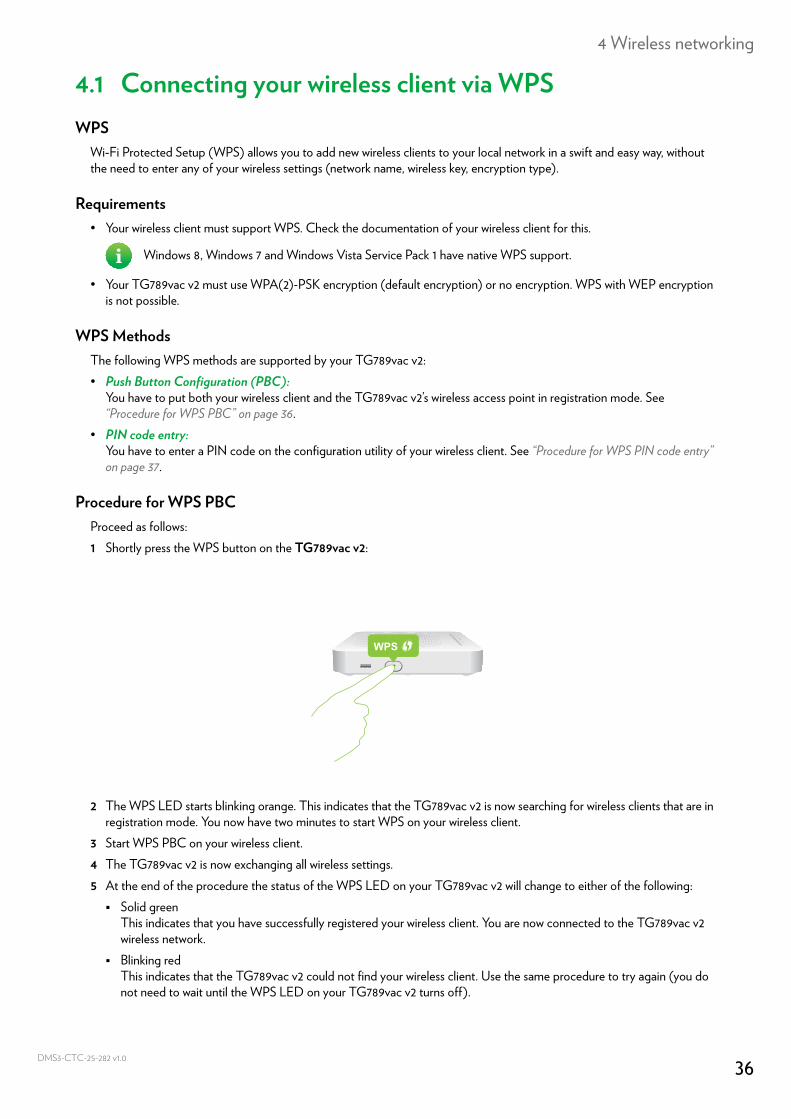
Procedure for WPS PBCProceed as follows:1 Shortly press the WPS button on the TG789vac v2:
2 The WPS LED starts blinking orange. This indicates that the TG789vac v2 is now searching for wireless clients that are in registration mode. You now have two minutes to start WPS on your wireless client.
3 Start WPS PBC on your wireless client.4 The TG789vac v2 is now exchanging all wireless settings.5 At the end of the procedure the status of the WPS LED on your TG789vac v2 will change to either of the following: Solid green
This indicates that you have successfully registered your wireless client. You are now connected to the TG789vac v2 wireless network.
Blinking redThis indicates that the TG789vac v2 could not find your wireless client. Use the same procedure to try again (you do not need to wait until the WPS LED on your TG789vac v2 turns off).
Windows 8, Windows 7 and Windows Vista Service Pack 1 have native WPS support.
WPS
36CTC-25-282 v1.0
4 Wireless networking
DMS3-
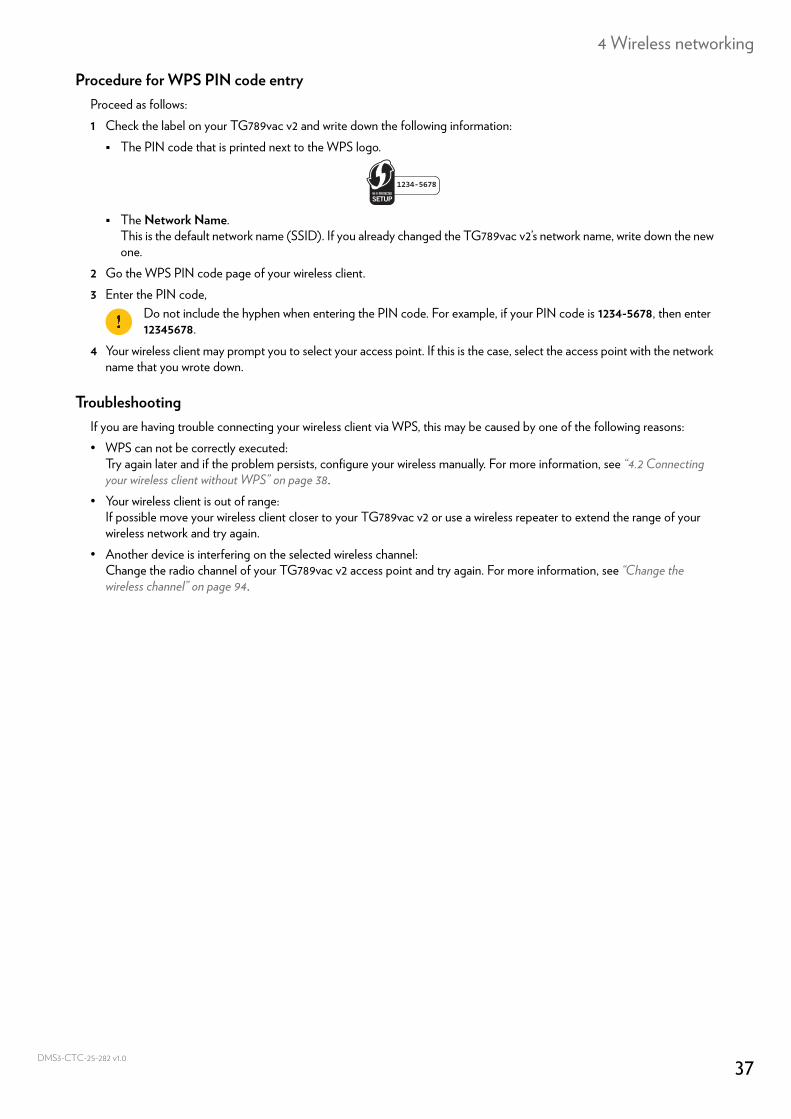
Procedure for WPS PIN code entryProceed as follows:1 Check the label on your TG789vac v2 and write down the following information: The PIN code that is printed next to the WPS logo.
The Network Name.This is the default network name (SSID). If you already changed the TG789vac v2’s network name, write down the new one.
2 Go the WPS PIN code page of your wireless client.3 Enter the PIN code,
4 Your wireless client may prompt you to select your access point. If this is the case, select the access point with the network name that you wrote down.
TroubleshootingIf you are having trouble connecting your wireless client via WPS, this may be caused by one of the following reasons:• WPS can not be correctly executed:
Try again later and if the problem persists, configure your wireless manually. For more information, see “4.2 Connecting your wireless client without WPS” on page 38.
• Your wireless client is out of range:If possible move your wireless client closer to your TG789vac v2 or use a wireless repeater to extend the range of your wireless network and try again.
• Another device is interfering on the selected wireless channel:Change the radio channel of your TG789vac v2 access point and try again. For more information, see “Change the wireless channel” on page 94.
Do not include the hyphen when entering the PIN code. For example, if your PIN code is 1234-5678, then enter 12345678.
1234-5678
37CTC-25-282 v1.0
4 Wireless networking
DMS3-
4.2 Connecting your wireless client without WPSBefore you start
Before you can connect a wireless client (for example, a computer) to your wireless network you need to know the wireless settings that are currently used by the TG789vac v2, i.e.:• The Network Name (SSID)• The wireless key
What Network Name (SSID) is my TG789vac v2 using?If you did not change the SSID, your TG789vac v2 uses the Network Name that is printed on the bottom panel label of your TG789vac v2.
What wireless key is my TG789vac v2 using?If you did not change the security settings, no wireless key is used.
Forgot your wireless key?If you have changed the wireless settings manually and you cant remember your settings, try one of the following:1 Use a computer that is already connected to your network.
2 Browse to the TG789vac v2 GUI.For more information, see “Accessing the TG789vac v2 GUI” on page 29.
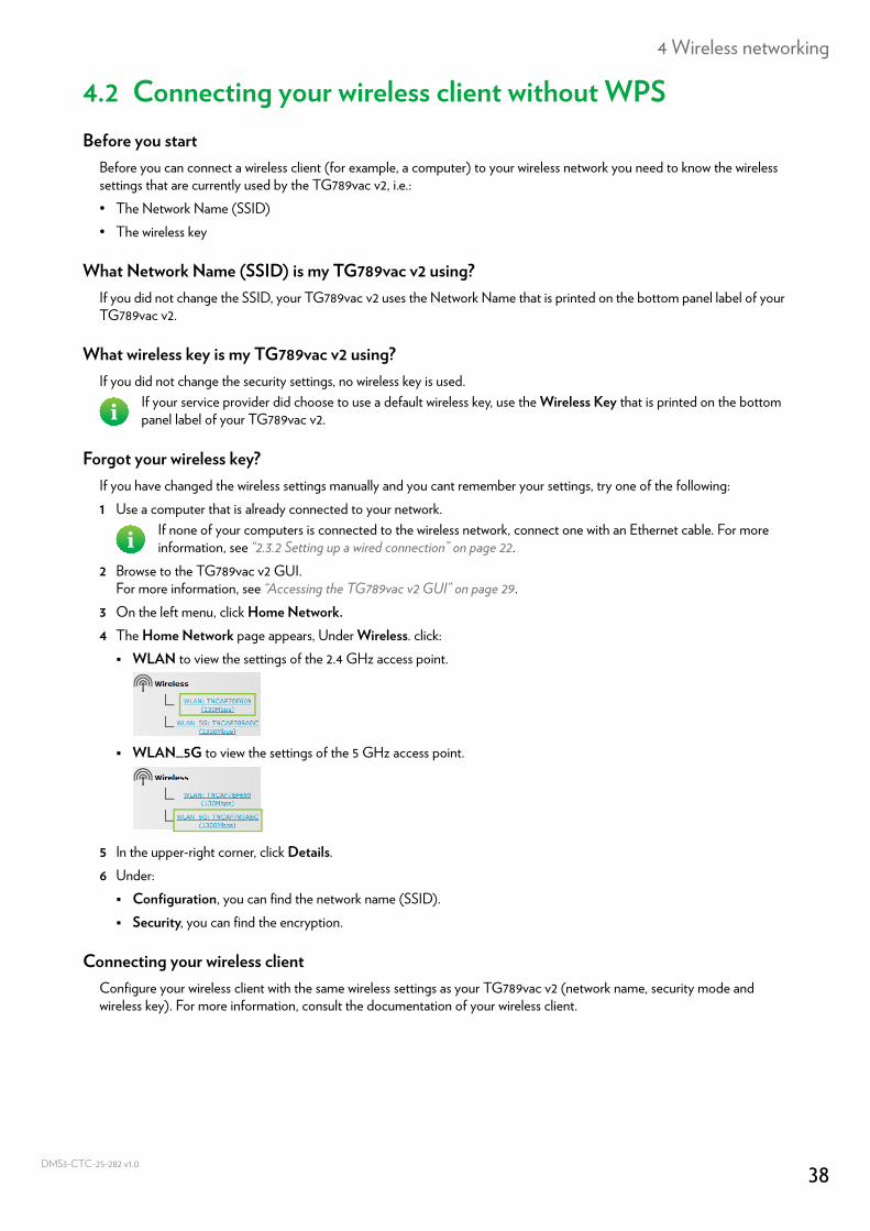
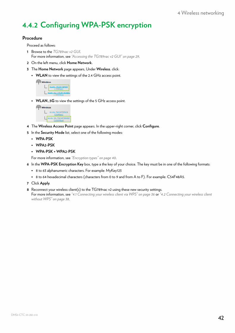
3 On the left menu, click Home Network.4 The Home Network page appears, Under Wireless. click: WLAN to view the settings of the 2.4 GHz access point.
WLAN_5G to view the settings of the 5 GHz access point.
5 In the upper-right corner, click Details.6 Under: Configuration, you can find the network name (SSID). Security, you can find the encryption.
Connecting your wireless clientConfigure your wireless client with the same wireless settings as your TG789vac v2 (network name, security mode and wireless key). For more information, consult the documentation of your wireless client.
If your service provider did choose to use a default wireless key, use the Wireless Key that is printed on the bottom panel label of your TG789vac v2.
If none of your computers is connected to the wireless network, connect one with an Ethernet cable. For more information, see “2.3.2 Setting up a wired connection” on page 22.
38CTC-25-282 v1.0
4 Wireless networking
DMS3-
4.3 Connecting your wireless client by scanning a QR codeIntroduction
The TG789vac v2 allows you to generate a Quick Response (QR) code that contains all wireless settings that are needed to connect. You are then able to connect to the wireless network by scanning the generated code.
Target devicesThis connection method is typically used for tablets and smartphones.
RequirementsYour wireless device must have:• A camera to scan the code.• An application (app) to interpret the QR code and connect to a wireless network.
For example: if you are using Android on your device, you may download Bar Code Scanner from Google Play.
ProcedureProceed as follows:1 Browse to the TG789vac v2 GUI.
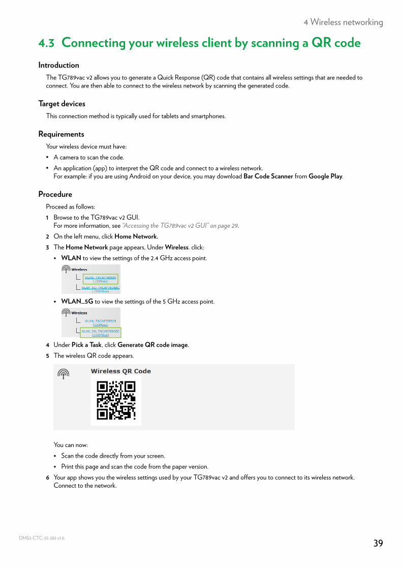
For more information, see “Accessing the TG789vac v2 GUI” on page 29.2 On the left menu, click Home Network.3 The Home Network page appears, Under Wireless. click: WLAN to view the settings of the 2.4 GHz access point.
WLAN_5G to view the settings of the 5 GHz access point.
4 Under Pick a Task, click Generate QR code image.5 The wireless QR code appears.
You can now: Scan the code directly from your screen. Print this page and scan the code from the paper version.
6 Your app shows you the wireless settings used by your TG789vac v2 and offers you to connect to its wireless network. Connect to the network.
39CTC-25-282 v1.0
4 Wireless networking
DMS3-
4.4 Securing your wireless connectionIntroduction
We recommend you to protect all wireless communication between the wireless clients and your TG789vac v2 with a wireless key. This means that:• Only clients that use the correct Network Name (SSID) and wireless key can connect to your network.• All data passing through your wireless access point is secured by encryption.
Encryption typesOver the years a number of encryption methods have been developed. The list below gives you an overview of the encryption types supported by the TG789vac v2 and ordered by descending security level; you will find the highest level of security at the top of the list:For Enterprise environment(s):• RADIUS Server (WPA):
Wireless clients first need to authenticate to the Remote Authentication Dial In User Service (RADIUS) server. The RADIUS server then provides the wireless key that must be used to encrypt its data. The RADIUS server regularly updates this key at a specified interval.
• If you do not have a RADIUS server in your network, use on the of the encryption types for home and small office environment.
For home or small office environment:• WPA-PSK Encryption:
The wireless connection is secured with a pre-shared key that has been defined by the user. Wireless clients must be configured with this key before they can connect to the TG789vac v2. The TG789vac v2 supports the following WPA-PSK versions (ordered by descending security): WPA2-PSK: the most recent and most secure version of WPA-PSK.
Choose this version if you are sure that all your wireless clients support WPA2-PSK. WPA-PSK + WPA2-PSK: this is a mixed mode.
In this mode WPA2-PSK, is the preferred encryption type but wireless clients do not support WPA2-PSK can still use WPA-PSK as encryption type. Choose this option if not all of your wireless clients support WPA2-PSK or if you are not sure. Wireless clients that support WPA2-PSK will use WPA2-PSK, the others will use WPA-PSK.
WPA-PSK: the first version of WPA-PSK.Choose this option if you are sure that none of your wireless clients support WPA2-PSK.
• WEP Encryption:The least safe encryption type used for wireless connections. Like WPA-PSK it uses a user-defined key, but WEP has been proven to have security issues.
ConfigurationTo secure your wireless network with:• WPA encryption (via RADIUS), continue with “4.4.1 Configuring WPA encryption” on page 41.• WPA-PSK encryption, continue with “4.4.2 Configuring WPA-PSK encryption” on page 42.
If you want to configure WPA2(-PSK) on the built-in wireless utility of Windows XP Service Pack 2 (SP2), you must first:• Upgrade your Windows XP to Service Pack 3.- or -• Install the following update: http://support.microsoft.com/kb/917021.
Although the TG789vac v2 allows you to use WEP or no security, we strongly advise against using one of them! Use WPA(2)-PSK or RADIUS instead.
40CTC-25-282 v1.0
4 Wireless networking
DMS3-
4.4.1 Configuring WPA encryptionProcedure
Proceed as follows:1 Browse to the TG789vac v2 GUI.
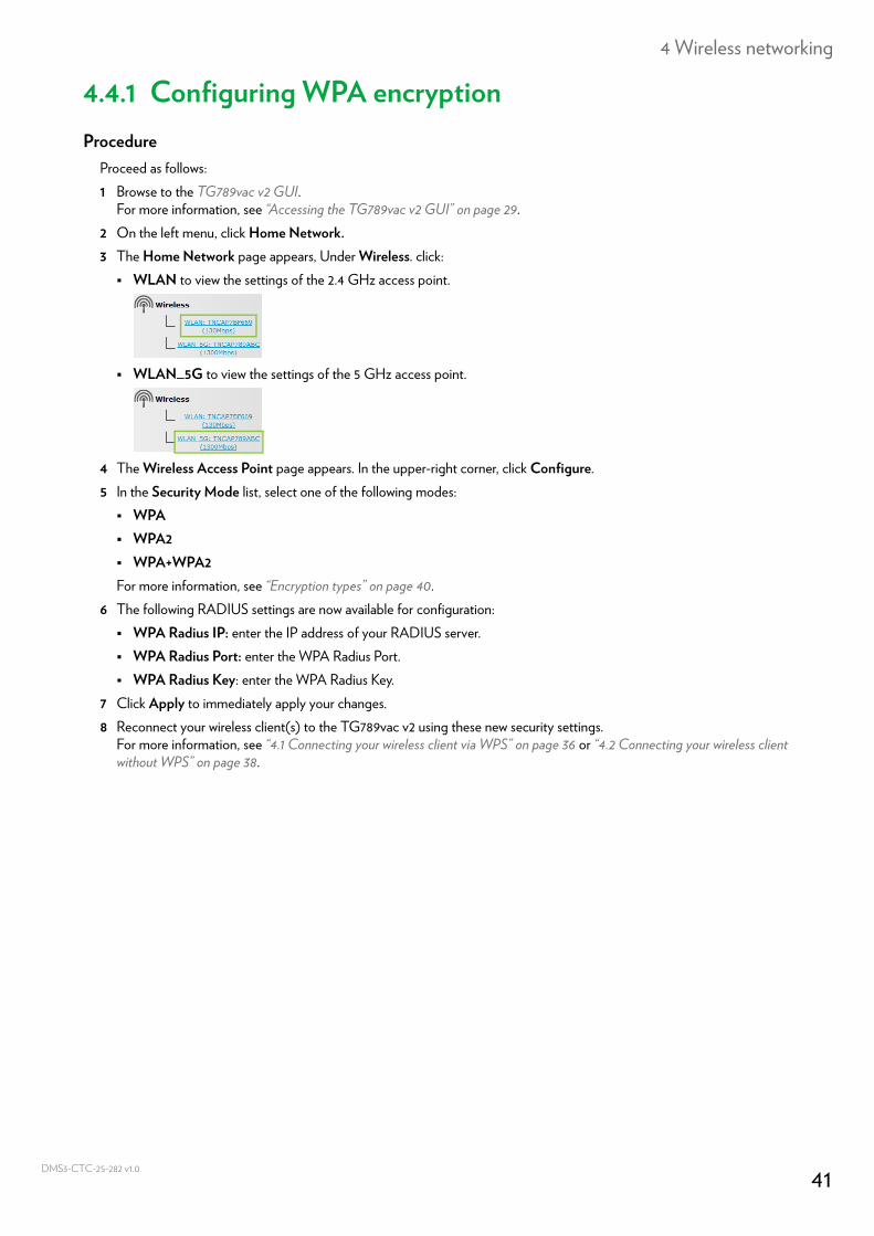
For more information, see “Accessing the TG789vac v2 GUI” on page 29.2 On the left menu, click Home Network.3 The Home Network page appears, Under Wireless. click: WLAN to view the settings of the 2.4 GHz access point.
WLAN_5G to view the settings of the 5 GHz access point.
4 The Wireless Access Point page appears. In the upper-right corner, click Configure.5 In the Security Mode list, select one of the following modes: WPA WPA2 WPA+WPA2For more information, see “Encryption types” on page 40.
6 The following RADIUS settings are now available for configuration: WPA Radius IP: enter the IP address of your RADIUS server. WPA Radius Port: enter the WPA Radius Port. WPA Radius Key: enter the WPA Radius Key.
7 Click Apply to immediately apply your changes.8 Reconnect your wireless client(s) to the TG789vac v2 using these new security settings.
For more information, see “4.1 Connecting your wireless client via WPS” on page 36 or “4.2 Connecting your wireless client without WPS” on page 38.
41CTC-25-282 v1.0
4 Wireless networking
DMS3-
4.4.2 Configuring WPA-PSK encryptionProcedure
Proceed as follows:1 Browse to the TG789vac v2 GUI.
For more information, see “Accessing the TG789vac v2 GUI” on page 29.2 On the left menu, click Home Network.3 The Home Network page appears, Under Wireless. click: WLAN to view the settings of the 2.4 GHz access point.
WLAN_5G to view the settings of the 5 GHz access point.
4 The Wireless Access Point page appears. In the upper-right corner, click Configure.5 In the Security Mode list, select one of the following modes: WPA-PSK WPA2-PSK WPA-PSK + WPA2-PSKFor more information, see “Encryption types” on page 40.
6 In the WPA-PSK Encryption Key box, type a the key of your choice. The key must be in one of the following formats: 8 to 63 alphanumeric characters. For example: MyKey123 8 to 64 hexadecimal characters (characters from 0 to 9 and from A to F). For example: C54F48A5.
7 Click Apply.8 Reconnect your wireless client(s) to the TG789vac v2 using these new security settings.
For more information, see “4.1 Connecting your wireless client via WPS” on page 36 or “4.2 Connecting your wireless client without WPS” on page 38.
42CTC-25-282 v1.0
5 Telephony
DMS3-
5 TelephonyVoice over IP (VoIP)
VoIP is a technology in which telephone calls are made over the Internet. This allows you to save on communication costs, especially for long-distance calls.
The expensive solutionTo be able to make your phone calls over the Internet you could either:• Buy an IP phone.
These IP phones are special phones that you can connect to your Internet Gateway.• Install VoIP software on your computer and make your phone calls via your computer.
The Technicolor solutionWith the TG789vac v2 you can make both VoIP and traditional telephone calls using a traditional analogue phone.If your TG789vac v2 is not powered, the traditional telephone network (if connected) will automatically be selected. This way you are still able to make emergency calls.
In this chapterThis chapter covers following topics:
Topic Page
5.1 Setting up your telephone network 44
5.2 Address book 47
5.3 Viewing call logs 49
43CTC-25-282 v1.0
5 Telephony
DMS3-
5.1 Setting up your telephone networkProcedure
To set up your telephone network, follow these steps:1 Connect your traditional phone(s), DECT base station or fax to the green Phone port(s) on the back panel of your
TG789vac v2.2 If your service provider did not yet configure the VoIP service, configure the VoIP service on your TG789vac v2.
For more information, see “5.1.1 Configuring the TG789vac v2 VoIP service” on page 45.
44CTC-25-282 v1.0
5 Telephony
DMS3-
5.1.1 Configuring the TG789vac v2 VoIP serviceIntroduction
In most cases the VoIP service will already be configured on your TG789vac v2. If this is not the case, follow the instructions from this section.
What you needYou service provider must provide the following information:• The proxy server address and port• The registrar server address and port• Your VoIP account information
How can I check if the VoIP service has already been configured?If the Voice LED is:• Solid or blinking green:
The VoIP service is configured correctly. No configuration is needed.• Off:
The VoIP service is not configured (yet). Follow the instructions below.
RequirementsYour Internet connection must be up and running before you are able to configure Internet telephony.
Configuring the VoIP settingsProceed as follows:1 Enter the proxy and registrar settings.2 Enter your VoIP account settings.
Enter the proxy and registrar settingsProceed as follows:1 Browse to the TG789vac v2 GUI.
For more information, see “Accessing the TG789vac v2 GUI” on page 29.2 On the Toolbox menu, click Telephony.3 In the Navigation bar, click Expert configure.4 Complete the following fields based on the settings provided by your VoIP provider: Proxy:
Type the URL (for example: sip.provider.com) or IP address of the proxy. Registrar:
Type the URL (for example: sip.provider.com) or IP address of the registrar. Registrar Port and Proxy Port.
In most cases the default port (5060) will be used. Only change these values if your provider instructed you to do so.5 Click Apply.
Enter your VoIP account settingsProceed as follows:1 Make sure that your TG789vac v2 is connected to the Internet.2 In the Navigation bar, click Configure.3 Under Service Configuration, select Enable Telephony.
45CTC-25-282 v1.0
5 Telephony
DMS3-
4 Under Telephone Numbers, complete the following fields: SIP URI:
The Uniform Resource Identifier (URI) of your SIP account (for example: +3235051979, john.doe,...). This is the telephone number that people have to dial to call you.
Username:The user name of your VoIP account (for example: +3235051979, john.doe,...).
Password:The password of your VoIP account.
Displayname:The name that you want people to see on the display of their phone when you are calling.
Abbreviated number:An internal number to call the phones associated with this VoIP account.
Port:The phone port that you want to associate with this VoIP account. Select• All to use this VoIP account for all connected phone.• Phone (1/2) to use this VoIP account for the phone connected to the Phone (1/2) port of your TG789vac v2.
5 Click Apply.6 Repeat this procedure for each VoIP account that you received.
Verifying Telephone ConnectivityProceed as follows to verify the voice connection:1 Make sure the TG789vac v2 is turned on.2 Make sure the Internet telephony service is enabled and configured. The Voice LED on your TG789vac v2 must be solid
green.3 Pick up your phone, wait for the dialling tone, and dial the number.
Your VoIP provider may not support this feature.
46CTC-25-282 v1.0
5 Telephony
DMS3-
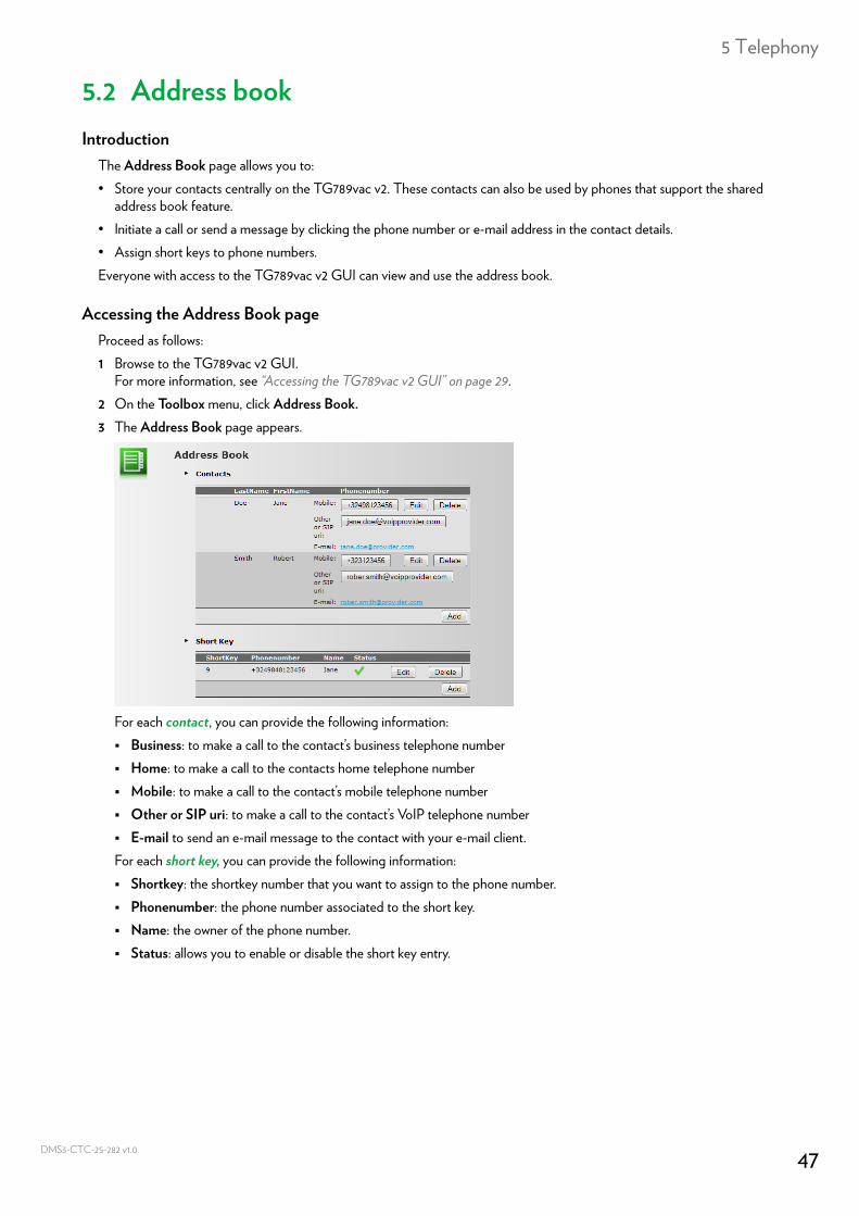
5.2 Address bookIntroduction
The Address Book page allows you to:• Store your contacts centrally on the TG789vac v2. These contacts can also be used by phones that support the shared
address book feature.• Initiate a call or send a message by clicking the phone number or e-mail address in the contact details.• Assign short keys to phone numbers.Everyone with access to the TG789vac v2 GUI can view and use the address book.
Accessing the Address Book pageProceed as follows:1 Browse to the TG789vac v2 GUI.
For more information, see “Accessing the TG789vac v2 GUI” on page 29.2 On the Toolbox menu, click Address Book.3 The Address Book page appears.
For each contact, you can provide the following information: Business: to make a call to the contact’s business telephone number Home: to make a call to the contacts home telephone number Mobile: to make a call to the contact’s mobile telephone number Other or SIP uri: to make a call to the contact’s VoIP telephone number E-mail to send an e-mail message to the contact with your e-mail client.For each short key, you can provide the following information: Shortkey: the shortkey number that you want to assign to the phone number. Phonenumber: the phone number associated to the short key. Name: the owner of the phone number. Status: allows you to enable or disable the short key entry.
47CTC-25-282 v1.0
5 Telephony
DMS3-
Managing contacts and short keys
All information provided per contact is optional except for the last and first name. The information can be updated or completed at any time.
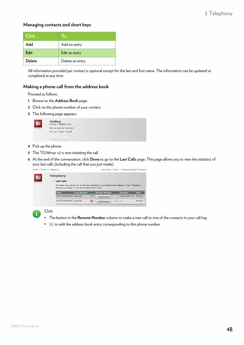
Making a phone call from the address bookProceed as follows:1 Browse to the Address Book page.2 Click on the phone number of your contact.3 The following page appears:
4 Pick up the phone.5 The TG789vac v2 is now initiating the call.6 At the end of the conversation, click Done to go to the Last Calls page. This page allows you to view the statistics of
your last calls (including the call that you just made).
Click... To...
Add Add an entry
Edit Edit an entry
Delete Delete an entry
Click:• The button in the Remote Number column to make a new call to one of the contacts in your call log.• to edit the address book entry corresponding to this phone number.
48CTC-25-282 v1.0
5 Telephony
DMS3-
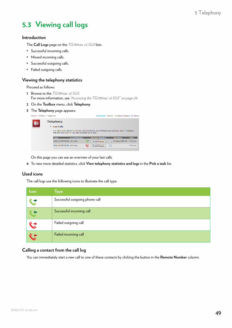
5.3 Viewing call logsIntroduction
The Call Logs page on the TG789vac v2 GUI lists:• Successful incoming calls.• Missed incoming calls.• Successful outgoing calls.• Failed outgoing calls.
Viewing the telephony statisticsProceed as follows:1 Browse to the TG789vac v2 GUI.
For more information, see “Accessing the TG789vac v2 GUI” on page 29.2 On the Toolbox menu, click Telephony.3 The Telephony page appears:
On this page you can see an overview of your last calls.4 To view more detailed statistics, click View telephony statistics and logs in the Pick a task list.
Used iconsThe call logs use the following icons to illustrate the call type:
Calling a contact from the call logYou can immediately start a new call to one of these contacts by clicking the button in the Remote Number column.
Icon Type
Successful outgoing phone call
Successful incoming call
Failed outgoing call
Failed incoming call
49CTC-25-282 v1.0

6 Saving energy
DMS3-
6 Saving energyCode of Conduct
To prove its commitment to protect the environment, Technicolor adheres to the Code of Conduct, a global agreement to reduce the power consumption of broadband access devices.For more information, see “6.1 Code of Conduct” on page 51.
Technicolor power saving innovationsTo further reduce the power consumption, Technicolor has developed the ECO manager. This system constantly monitors the services provided by the TG789vac v2 and automatically switches unused services to an ECO-friendly state. For more information, see “6.2 ECO manager” on page 52.
50CTC-25-282 v1.0
6 Saving energy
DMS3-
6.1 Code of ConductPower states
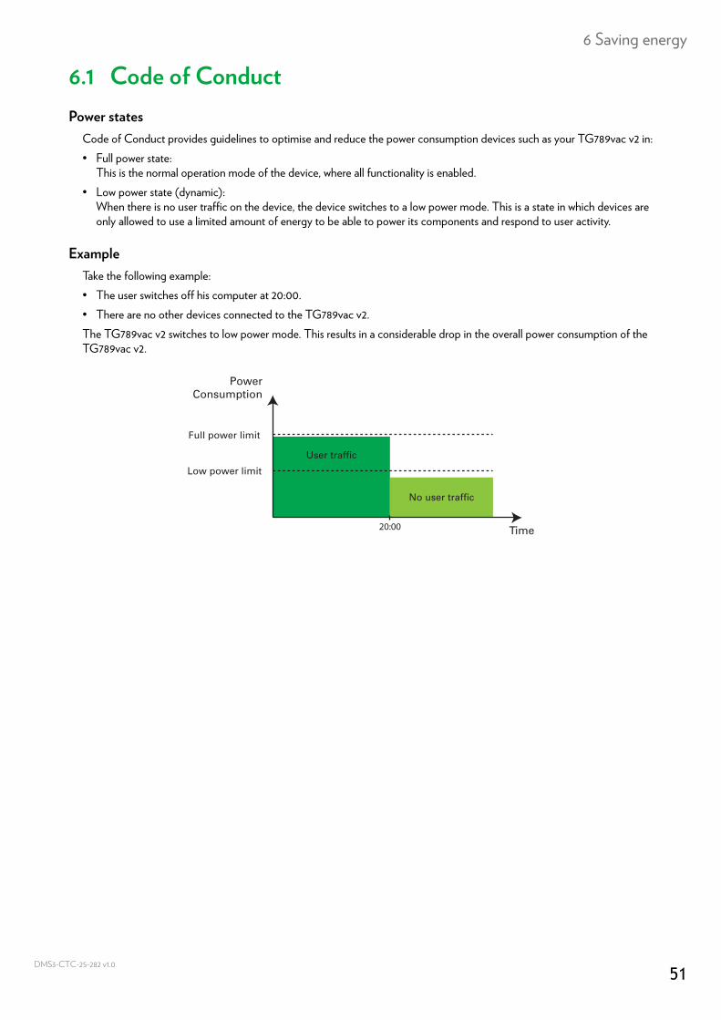
Code of Conduct provides guidelines to optimise and reduce the power consumption devices such as your TG789vac v2 in:• Full power state:
This is the normal operation mode of the device, where all functionality is enabled.• Low power state (dynamic):
When there is no user traffic on the device, the device switches to a low power mode. This is a state in which devices are only allowed to use a limited amount of energy to be able to power its components and respond to user activity.
ExampleTake the following example:• The user switches off his computer at 20:00.• There are no other devices connected to the TG789vac v2.The TG789vac v2 switches to low power mode. This results in a considerable drop in the overall power consumption of the TG789vac v2.
No user traffic
User traffic
Time
PowerConsumption
Full power limit
Low power limit
20:00
51CTC-25-282 v1.0
6 Saving energy
DMS3-
6.2 ECO managerIntroduction
The TG789vac v2 constantly monitors all the user activity via the TG789vac v2 and uses this information to optimise its power consumption:For example:• The TG789vac v2 is able to reduce the clock frequency of its central processor when there is no or low user activity. This
lowered clock frequency will result in a lower power consumption of the TG789vac v2.• Disable the USB port(s) when they are not used• Reduce its Ethernet switch functionality to link detection when there are no devices connected to the Ethernet port.• Switch its wireless interface to power reduction mode.
Wireless access point power reduction modeWhen the TG789vac v2 access point switches to power reduction mode, the access point is switched off and is only switched on periodically to allow to detect new wireless clients. If new clients are detected the wireless access point is immediately fully powered again.
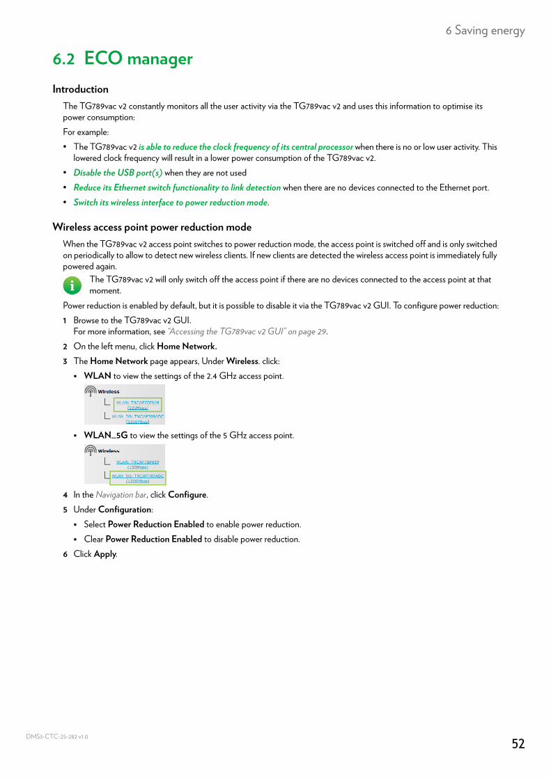
Power reduction is enabled by default, but it is possible to disable it via the TG789vac v2 GUI. To configure power reduction:1 Browse to the TG789vac v2 GUI.
For more information, see “Accessing the TG789vac v2 GUI” on page 29.2 On the left menu, click Home Network.3 The Home Network page appears, Under Wireless. click: WLAN to view the settings of the 2.4 GHz access point.
WLAN_5G to view the settings of the 5 GHz access point.
4 In the Navigation bar, click Configure.5 Under Configuration: Select Power Reduction Enabled to enable power reduction. Clear Power Reduction Enabled to disable power reduction.
6 Click Apply.
The TG789vac v2 will only switch off the access point if there are no devices connected to the access point at that moment.
52CTC-25-282 v1.0
6 Saving energy
DMS3-
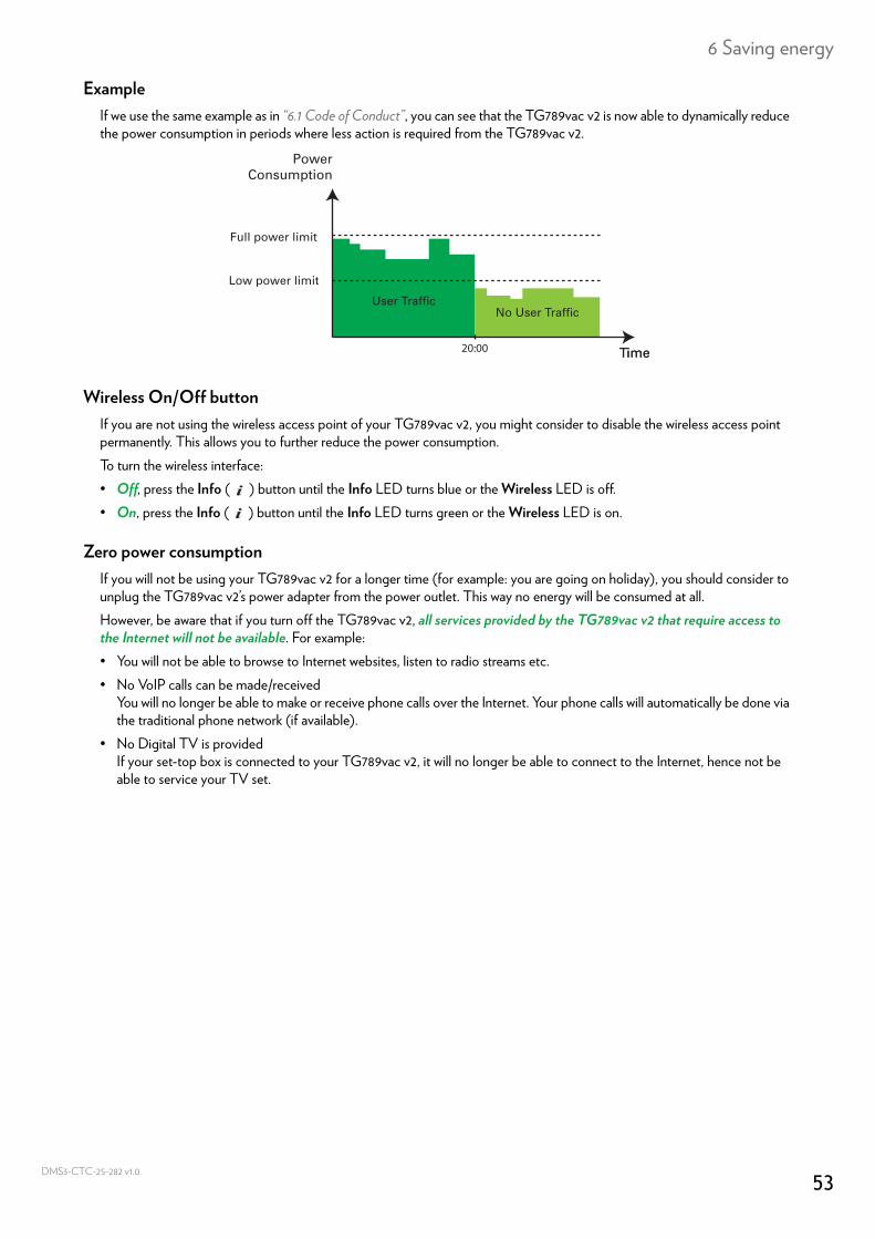
ExampleIf we use the same example as in “6.1 Code of Conduct”, you can see that the TG789vac v2 is now able to dynamically reduce the power consumption in periods where less action is required from the TG789vac v2.
Wireless On/Off buttonIf you are not using the wireless access point of your TG789vac v2, you might consider to disable the wireless access point permanently. This allows you to further reduce the power consumption.To turn the wireless interface:• Off, press the Info ( ) button until the Info LED turns blue or the Wireless LED is off.• On, press the Info ( ) button until the Info LED turns green or the Wireless LED is on.
Zero power consumptionIf you will not be using your TG789vac v2 for a longer time (for example: you are going on holiday), you should consider to unplug the TG789vac v2’s power adapter from the power outlet. This way no energy will be consumed at all.However, be aware that if you turn off the TG789vac v2, all services provided by the TG789vac v2 that require access to the Internet will not be available. For example:• You will not be able to browse to Internet websites, listen to radio streams etc.• No VoIP calls can be made/received
You will no longer be able to make or receive phone calls over the Internet. Your phone calls will automatically be done via the traditional phone network (if available).
• No Digital TV is providedIf your set-top box is connected to your TG789vac v2, it will no longer be able to connect to the Internet, hence not be able to service your TV set.
No User TrafficUser Traffic
Time20:00 Time
PowerConsumption
Full power limit
Low power limit
53CTC-25-282 v1.0
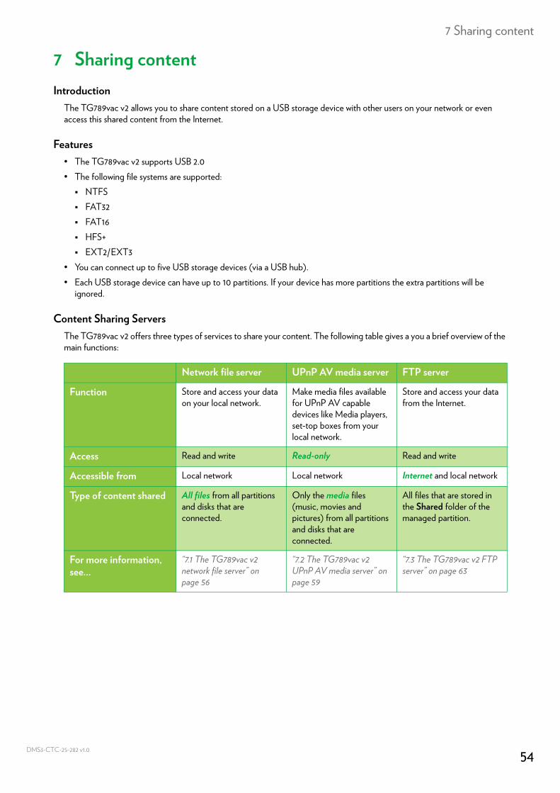
7 Sharing content
DMS3-
7 Sharing contentIntroduction
The TG789vac v2 allows you to share content stored on a USB storage device with other users on your network or even access this shared content from the Internet.
Features• The TG789vac v2 supports USB 2.0• The following file systems are supported: NTFS FAT32 FAT16 HFS+ EXT2/EXT3
• You can connect up to five USB storage devices (via a USB hub).• Each USB storage device can have up to 10 partitions. If your device has more partitions the extra partitions will be
ignored.
Content Sharing ServersThe TG789vac v2 offers three types of services to share your content. The following table gives a you a brief overview of the main functions:
Network file server UPnP AV media server FTP server
Function Store and access your data on your local network.
Make media files available for UPnP AV capable devices like Media players, set-top boxes from your local network.
Store and access your data from the Internet.
Access Read and write Read-only Read and write
Accessible from Local network Local network Internet and local network
Type of content shared All files from all partitions and disks that are connected.
Only the media files (music, movies and pictures) from all partitions and disks that are connected.
All files that are stored in the Shared folder of the managed partition.
For more information, see...
“7.1 The TG789vac v2 network file server” on page 56
“7.2 The TG789vac v2 UPnP AV media server” on page 59
“7.3 The TG789vac v2 FTP server” on page 63
54CTC-25-282 v1.0
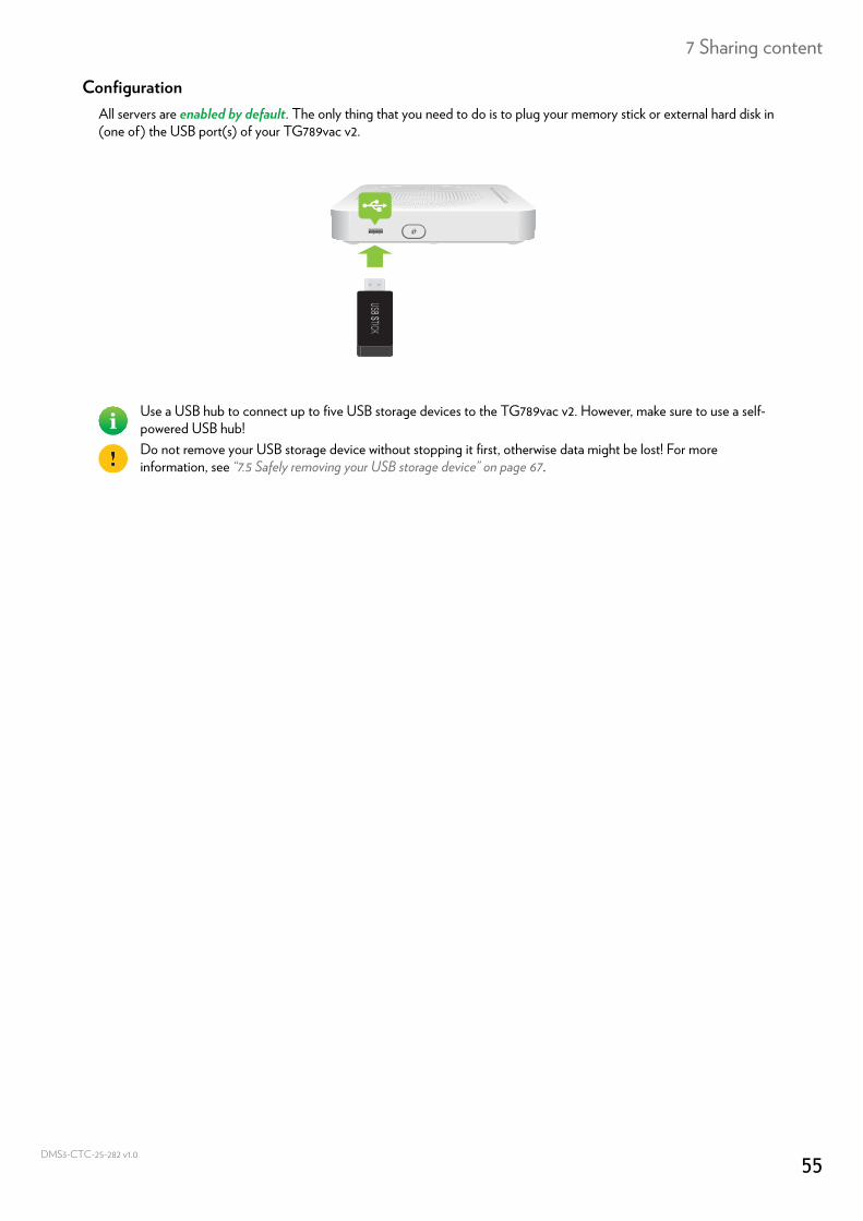
7 Sharing content
DMS3-
ConfigurationAll servers are enabled by default. The only thing that you need to do is to plug your memory stick or external hard disk in (one of) the USB port(s) of your TG789vac v2.
Use a USB hub to connect up to five USB storage devices to the TG789vac v2. However, make sure to use a self-powered USB hub!Do not remove your USB storage device without stopping it first, otherwise data might be lost! For more information, see “7.5 Safely removing your USB storage device” on page 67.
55CTC-25-282 v1.0
7 Sharing content
DMS3-
7.1 The TG789vac v2 network file serverIntroduction
The network server allows you to share content on your storage device(s) with other devices that are connected to your local network (mostly computers).
ConfigurationThe network file server is enabled by default and ready for use.To change the default settings, proceed as follows:1 Browse to the TG789vac v2 GUI.
For more information, see “Accessing the TG789vac v2 GUI” on page 29.2 On the Toolbox menu, click Content Sharing.3 In the Navigation bar, click Configure.4 Under Network File Server, you can change the following settings: Server Name:
Enter the name that you want to use for the TG789vac v2 shared content. Server Description:
Add a short description for the TG789vac v2 shared content. Workgroup:
Enter the same workgroup as used by your computer(s). Server Enabled:
Select this option to enable the network file server.5 Click Apply.6 All users connected to the TG789vac v2 can now access the data stored on the storage device(s) that are connected to
the TG789vac v2.7 If you want to limit the number of folders that can be accessed, continue with “7.4 Working with managed partitions” on
page 65.
Accessing the shared content on WindowsProceed as follows:1 Open Windows Explorer.2 In the address bar, type two backslashes followed by the server name that you provided (default: \\Technicolor).
These devices have read and write access to this USB device(s).
If you did not provide a server name, type \\192.168.1.253.If you made changes to the DHCP settings, the IP address may also have changed. For more information, see “Getting the IP address of your USB storage device” on page 97.
56CTC-25-282 v1.0
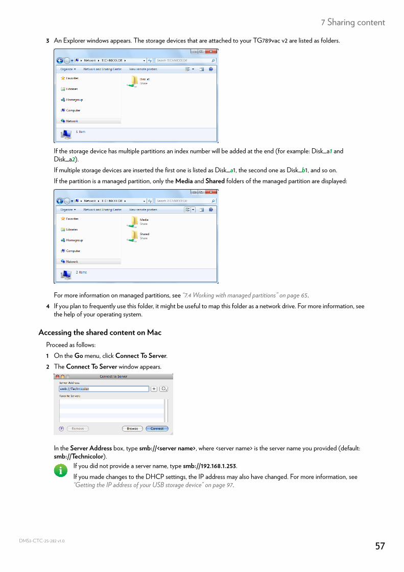
7 Sharing content
DMS3-
3 An Explorer windows appears. The storage devices that are attached to your TG789vac v2 are listed as folders.
If the storage device has multiple partitions an index number will be added at the end (for example: Disk_a1 and Disk_a2).If multiple storage devices are inserted the first one is listed as Disk_a1, the second one as Disk_b1, and so on.If the partition is a managed partition, only the Media and Shared folders of the managed partition are displayed:
For more information on managed partitions, see “7.4 Working with managed partitions” on page 65.4 If you plan to frequently use this folder, it might be useful to map this folder as a network drive. For more information, see
the help of your operating system.
Accessing the shared content on MacProceed as follows:1 On the Go menu, click Connect To Server.2 The Connect To Server window appears.
In the Server Address box, type smb://<server name>, where <server name> is the server name you provided (default: smb://Technicolor).
If you did not provide a server name, type smb://192.168.1.253.If you made changes to the DHCP settings, the IP address may also have changed. For more information, see “Getting the IP address of your USB storage device” on page 97.
57CTC-25-282 v1.0
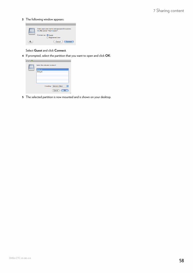
7 Sharing content
DMS3-
3 The following window appears:
Select Guest and click Connect.4 If prompted, select the partition that you want to open and click OK:
5 The selected partition is now mounted and is shown on your desktop.
58CTC-25-282 v1.0
7 Sharing content
DMS3-
7.2 The TG789vac v2 UPnP AV media serverIntroduction
Your TG789vac v2 has a built-in DLNA-certified UPnP AV media server. This section describes how to use and configure this media server.
UPnP AVUPnP AV (AV stands for Audio and Video) is a protocol especially designed to share media files on your local network.
DLNA-certifiedThe Digital Living Network Alliance (DLNA) is an organisation that imposes requirements to ensure the interoperatability of your media devices and standardize the communication between them.Buying a DLNA-certified device like the TG789vac v2 guarantees you that it will seamlessly integrate with your other DLNA-certified devices.To allow you to access your media in a quick and easy way, the TG789vac v2 scans your storage device for meta data information (for example, title, artist, album) and stores it in a database. When you are looking for a file, the TG789vac v2 can simply query the database instead of having to go through all the files.
UPnP AV network componentsA UPnP AV network consists of the following components:• The UPnP AV server is directly connected to your media files and makes them available on the network. In your network
the TG789vac v2 will fulfil this role.• The UPnP AV client is a software application or hardware device that allows you to play or view the media files provided
by your UPnP AV media server.
This database will only be created if the following conditions are met:• Your disk or partition must have at least 250MB of free space• Your disk or partition must not be read-only.
59CTC-25-282 v1.0
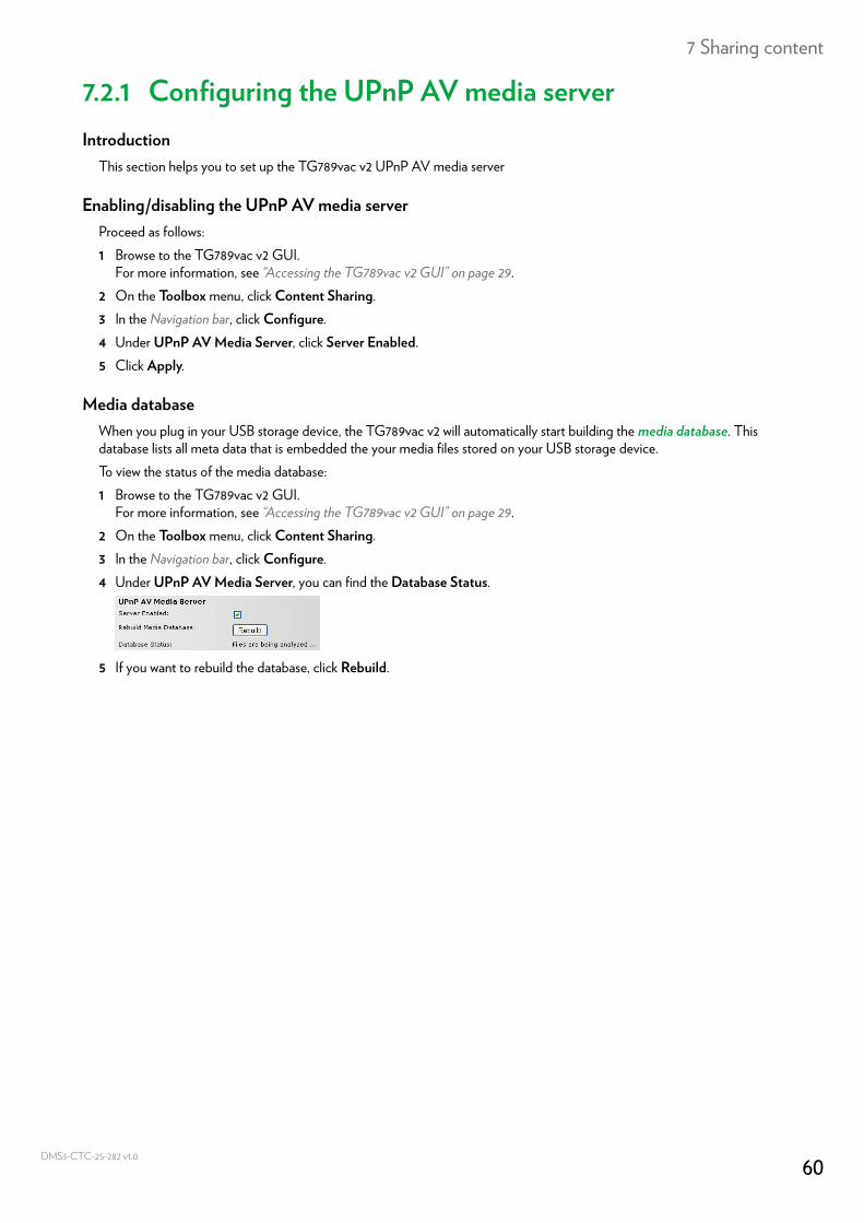
7 Sharing content
DMS3-
7.2.1 Configuring the UPnP AV media serverIntroduction
This section helps you to set up the TG789vac v2 UPnP AV media server
Enabling/disabling the UPnP AV media serverProceed as follows:1 Browse to the TG789vac v2 GUI.
For more information, see “Accessing the TG789vac v2 GUI” on page 29.2 On the Toolbox menu, click Content Sharing.3 In the Navigation bar, click Configure.4 Under UPnP AV Media Server, click Server Enabled.5 Click Apply.
Media databaseWhen you plug in your USB storage device, the TG789vac v2 will automatically start building the media database. This database lists all meta data that is embedded the your media files stored on your USB storage device.To view the status of the media database:1 Browse to the TG789vac v2 GUI.
For more information, see “Accessing the TG789vac v2 GUI” on page 29.2 On the Toolbox menu, click Content Sharing.3 In the Navigation bar, click Configure.4 Under UPnP AV Media Server, you can find the Database Status.
5 If you want to rebuild the database, click Rebuild.
60CTC-25-282 v1.0
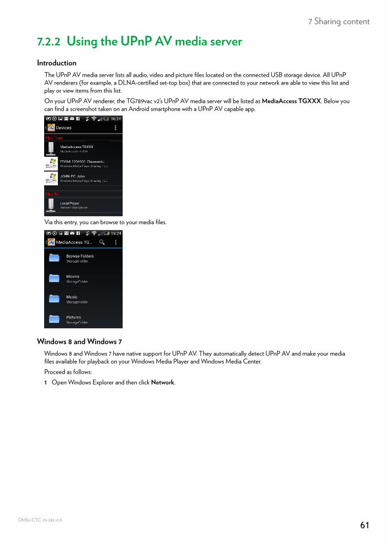
7 Sharing content
DMS3-
7.2.2 Using the UPnP AV media serverIntroduction
The UPnP AV media server lists all audio, video and picture files located on the connected USB storage device. All UPnP AV renderers (for example, a DLNA-certified set-top box) that are connected to your network are able to view this list and play or view items from this list.On your UPnP AV renderer, the TG789vac v2’s UPnP AV media server will be listed as MediaAccess TGXXX. Below you can find a screenshot taken on an Android smartphone with a UPnP AV capable app.
Via this entry, you can browse to your media files.
Windows 8 and Windows 7Windows 8 and Windows 7 have native support for UPnP AV. They automatically detect UPnP AV and make your media files available for playback on your Windows Media Player and Windows Media Center.Proceed as follows:1 Open Windows Explorer and then click Network.
61CTC-25-282 v1.0
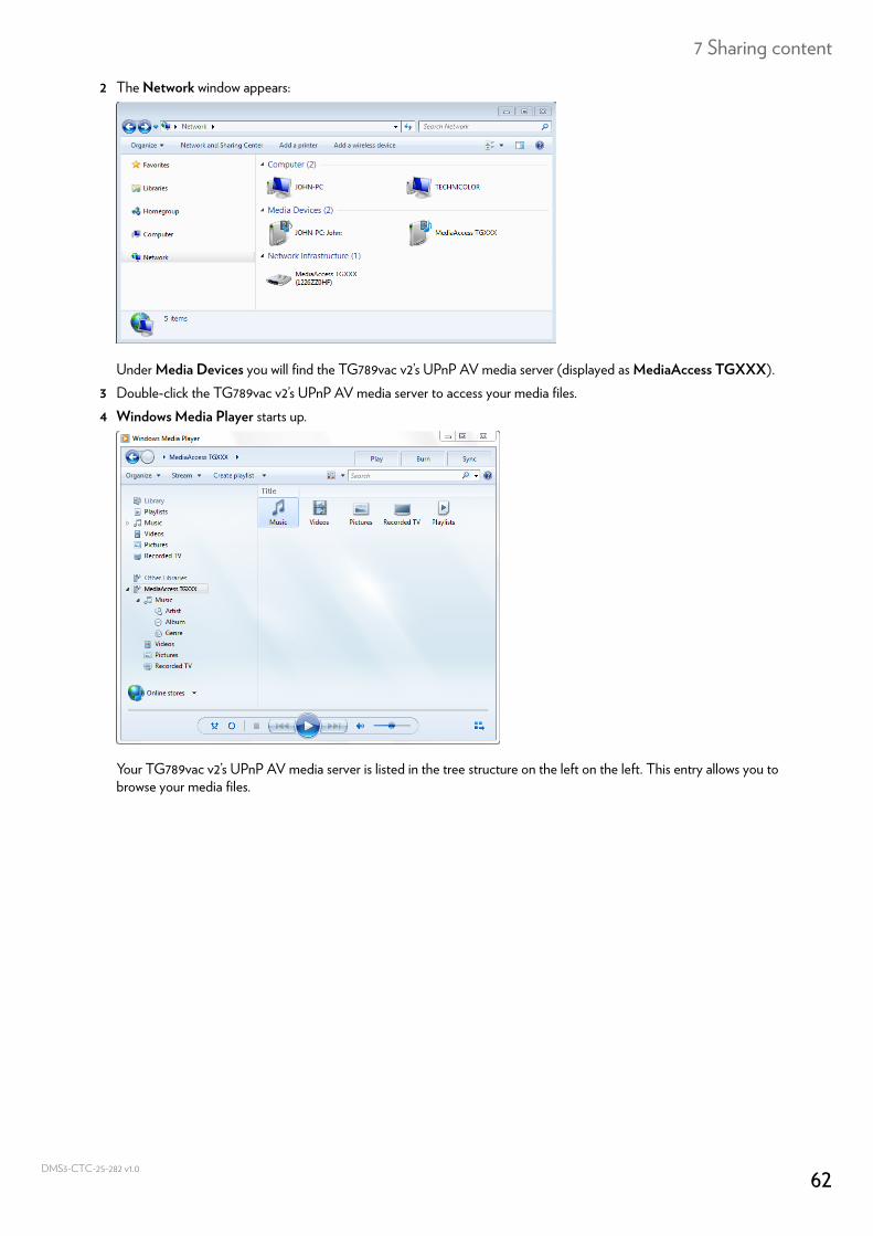
7 Sharing content
DMS3-
2 The Network window appears:
Under Media Devices you will find the TG789vac v2’s UPnP AV media server (displayed as MediaAccess TGXXX).3 Double-click the TG789vac v2’s UPnP AV media server to access your media files.4 Windows Media Player starts up.
Your TG789vac v2’s UPnP AV media server is listed in the tree structure on the left on the left. This entry allows you to browse your media files.
62CTC-25-282 v1.0
7 Sharing content
DMS3-
7.3 The TG789vac v2 FTP serverIntroduction
The TG789vac v2 allows you to access your shared content by FTP. This can be useful if you want to be able to access your shared content from the Internet.Via FTP you can download and upload all types of files both from your local network and the Internet.
Setting up the FTP serverProceed as follows:1 Protect your account with a password.2 Enable the FTP server and select the managed partition.
Protect your account with a passwordIf you did not yet configure your login to the TG789vac v2 GUI with a password:1 Browse to the TG789vac v2 GUI.
For more information, see “Accessing the TG789vac v2 GUI” on page 29.2 On the Toolbox menu, click User Management.3 In the Pick a task list, click Change my password.4 Leave the Old Password box empty.5 Type your new password both in the New Password box and Confirm New Password box.
Enable the FTP server and select the managed partitionProceed as follows:1 Browse to the TG789vac v2 GUI.
For more information, see “Accessing the TG789vac v2 GUI” on page 29.2 On the Toolbox menu, click Content Sharing.3 In the Navigation bar, click Configure.4 Under FTP Server, click Server Enabled.5 Under List of connected disks, click the radio button next to the partition to make it managed.6 The TG789vac v2 now creates a Media and Shared folder on the selected partition. The Shared folder will be used as
root location for FTP sessions.
7 Click Apply.
The Media folder is not accessible via FTP and can only be accessed via the network file server and the UPnP AV media server.
63CTC-25-282 v1.0
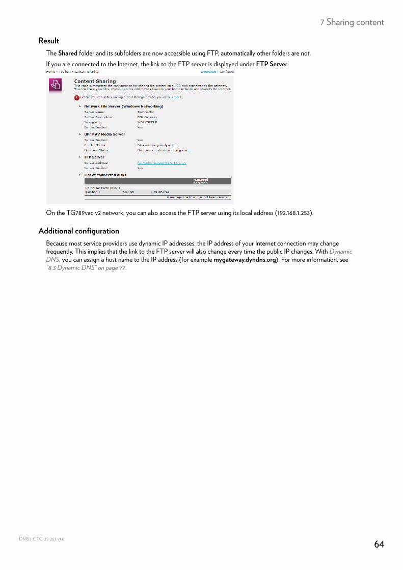
7 Sharing content
DMS3-
ResultThe Shared folder and its subfolders are now accessible using FTP, automatically other folders are not.If you are connected to the Internet, the link to the FTP server is displayed under FTP Server:
On the TG789vac v2 network, you can also access the FTP server using its local address (192.168.1.253).
Additional configurationBecause most service providers use dynamic IP addresses, the IP address of your Internet connection may change frequently. This implies that the link to the FTP server will also change every time the public IP changes. With Dynamic DNS, you can assign a host name to the IP address (for example mygateway.dyndns.org). For more information, see “8.3 Dynamic DNS” on page 77.
64CTC-25-282 v1.0
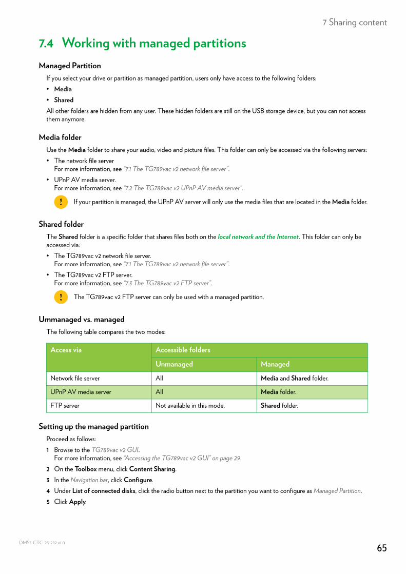
7 Sharing content
DMS3-
7.4 Working with managed partitionsManaged Partition
If you select your drive or partition as managed partition, users only have access to the following folders:• Media• SharedAll other folders are hidden from any user. These hidden folders are still on the USB storage device, but you can not access them anymore.
Media folderUse the Media folder to share your audio, video and picture files. This folder can only be accessed via the following servers:• The network file server
For more information, see “7.1 The TG789vac v2 network file server”.• UPnP AV media server.
For more information, see “7.2 The TG789vac v2 UPnP AV media server”.
Shared folderThe Shared folder is a specific folder that shares files both on the local network and the Internet. This folder can only be accessed via:• The TG789vac v2 network file server.
For more information, see “7.1 The TG789vac v2 network file server”.• The TG789vac v2 FTP server.
For more information, see “7.3 The TG789vac v2 FTP server”.
Ummanaged vs. managedThe following table compares the two modes:
Setting up the managed partitionProceed as follows:1 Browse to the TG789vac v2 GUI.
For more information, see “Accessing the TG789vac v2 GUI” on page 29.2 On the Toolbox menu, click Content Sharing.3 In the Navigation bar, click Configure.4 Under List of connected disks, click the radio button next to the partition you want to configure as Managed Partition.5 Click Apply.
If your partition is managed, the UPnP AV server will only use the media files that are located in the Media folder.
The TG789vac v2 FTP server can only be used with a managed partition.
Access via Accessible folders
Unmanaged Managed
Network file server All Media and Shared folder.
UPnP AV media server All Media folder.
FTP server Not available in this mode. Shared folder.
65CTC-25-282 v1.0

7 Sharing content
DMS3-
ResultThe TG789vac v2 creates following folders:• Media:
Use this folder to share your media files with others users on your network. You can store your media files in following subfolders: Movies Music Pictures
• Shared:Use this folder to share your (non-media) data with other users on your network. Optionally, users can also access this folder using FTP. For more information, see “7.3 The TG789vac v2 FTP server” on page 63.
If the above folders already exist, the existing folders are used.
66CTC-25-282 v1.0
7 Sharing content
DMS3-
7.5 Safely removing your USB storage deviceIntroduction
If you just unplug your USB storage device from the TG789vac v2 you may loose your data. To avoid this you must first stop your USB storage device.
Stopping your USB storage deviceProceed as follows1 Browse to the TG789vac v2 GUI.
For more information, see “Accessing the TG789vac v2 GUI” on page 29.2 On the Toolbox menu, click Content Sharing.3 In the Navigation bar, click Configure.4 Click Stop.5 Unplug your USB storage device from the TG789vac v2.
67CTC-25-282 v1.0
8 Network Services
DMS3-
8 Network ServicesIn this chapter
In this chapter we will take a closer look at following features:
Feature availabilitySome features may not be available on your TG789vac v2. For more information, contact your service provider.
Topic Page
8.1 UPnP 69
8.2 Assigning services (HTTP, FTP,...) to a computer 75
8.3 Dynamic DNS 77
8.4 Network time server 78
68CTC-25-282 v1.0
8 Network Services
DMS3-
8.1 UPnPIntroduction
UPnP is designed to automate the installation and configuration of a home network as much as possible. This means that UPnP-capable devices can join and leave a network without any effort of a network administrator.
Supported Operating SystemsThe following operating systems support UPnP:• Windows 8• Windows 7• Windows Vista• Windows XP
UPnP and the TG789vac v2UPnP offers you the following functions:• You can access the TG789vac v2 GUI on your local network without having to remember the address of the
TG789vac v2. For more information, see “8.1.1 Accessing your TG789vac v2 via UPnP” on page 70.• If you are using a PPP connection to connect to the Internet, you can enable/disable your Internet connection without
having to open the TG789vac v2 GUI.For more information, see “8.1.2 Managing your Internet connection via UPnP” on page 71.
• You do not have to manually create port mappings to run services on a computer. The automatic port configuration mechanism for UPnP-enabled games and applications will do this for you. If the application is UPnP-enabled, UPnP will create these entries automatically. For more information, see “8.2 Assigning services (HTTP, FTP,...) to a computer” on page 75.
If your computer is running Windows XP, you first have to install the UPnP component. For more information, see “8.1.4 Installing UPnP on Windows XP” on page 73.
69CTC-25-282 v1.0
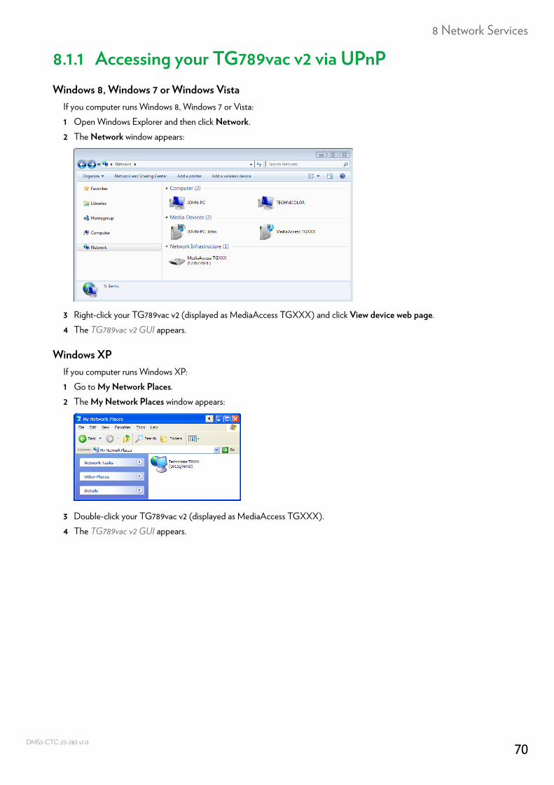
8 Network Services
DMS3-
8.1.1 Accessing your TG789vac v2 via UPnPWindows 8, Windows 7 or Windows Vista
If you computer runs Windows 8, Windows 7 or Vista:1 Open Windows Explorer and then click Network.2 The Network window appears:
3 Right-click your TG789vac v2 (displayed as MediaAccess TGXXX) and click View device web page.4 The TG789vac v2 GUI appears.
Windows XPIf you computer runs Windows XP:1 Go to My Network Places.2 The My Network Places window appears:
3 Double-click your TG789vac v2 (displayed as MediaAccess TGXXX).4 The TG789vac v2 GUI appears.
70CTC-25-282 v1.0
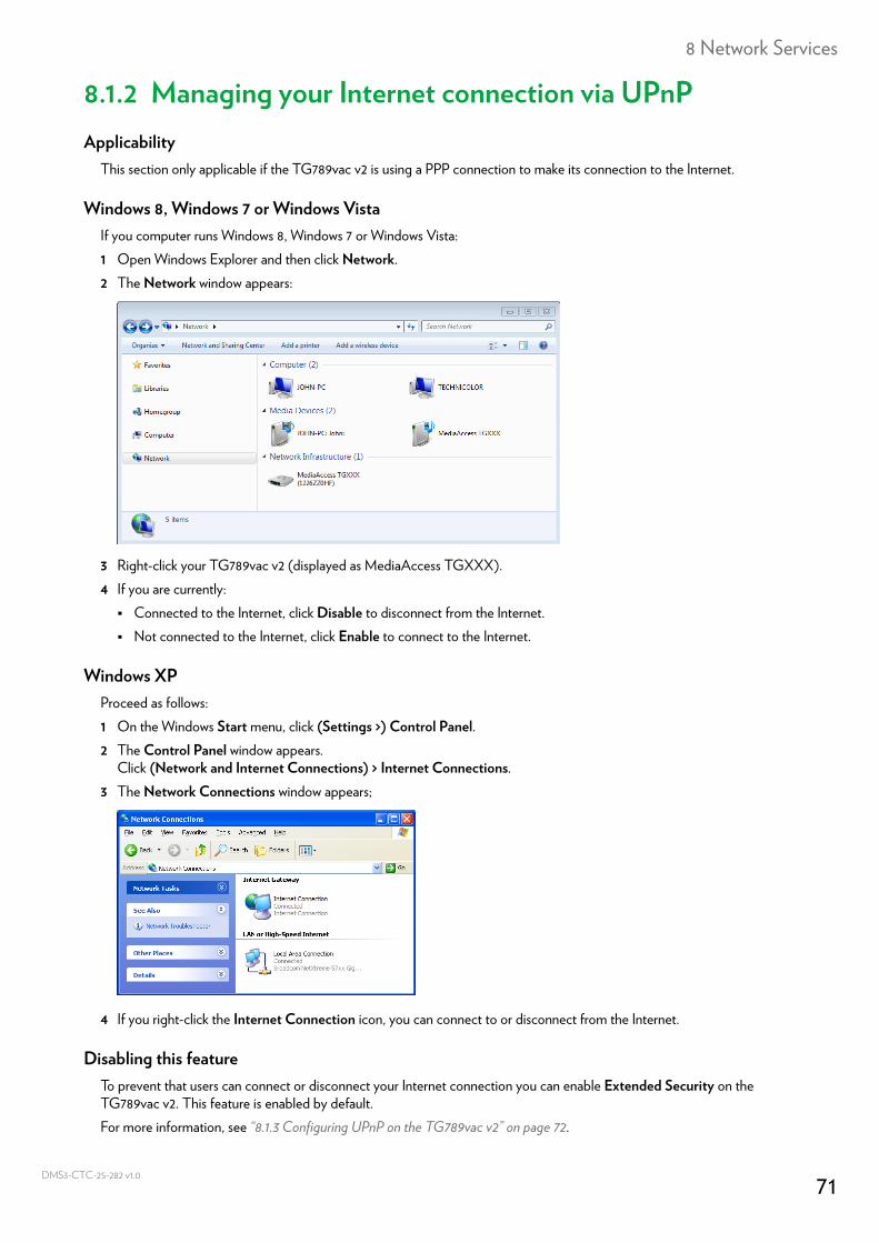
8 Network Services
DMS3-
8.1.2 Managing your Internet connection via UPnPApplicability
This section only applicable if the TG789vac v2 is using a PPP connection to make its connection to the Internet.
Windows 8, Windows 7 or Windows VistaIf you computer runs Windows 8, Windows 7 or Windows Vista:1 Open Windows Explorer and then click Network.2 The Network window appears:
3 Right-click your TG789vac v2 (displayed as MediaAccess TGXXX).4 If you are currently: Connected to the Internet, click Disable to disconnect from the Internet. Not connected to the Internet, click Enable to connect to the Internet.
Windows XPProceed as follows:1 On the Windows Start menu, click (Settings >) Control Panel.2 The Control Panel window appears.
Click (Network and Internet Connections) > Internet Connections.3 The Network Connections window appears;
4 If you right-click the Internet Connection icon, you can connect to or disconnect from the Internet.
Disabling this featureTo prevent that users can connect or disconnect your Internet connection you can enable Extended Security on the TG789vac v2. This feature is enabled by default.For more information, see “8.1.3 Configuring UPnP on the TG789vac v2” on page 72.
71CTC-25-282 v1.0
8 Network Services
DMS3-
8.1.3 Configuring UPnP on the TG789vac v2Introduction
On the TG789vac v2 GUI you can:• Enable/Disable UPnP.• Enable/Disable Extended Security.
Enable/Disable UPnPProceed as follows:1 Browse to the TG789vac v2 GUI.
For more information, see “Accessing the TG789vac v2 GUI” on page 29.2 On the Toolbox menu, click Game & Application Sharing.3 Under Universal Plug and Play: Select the Use UPnP check box, to enable UPnP. Clear the Use UPnP check box, to disable UPnP.
4 Click Apply.
Extended SecurityIf Extended Security is enabled, only limited UPnP operation between the host and the TG789vac v2 is allowed:• A local host is not allowed to connect/disconnect the TG789vac v2 Internet connection. You can then only connect/
disconnect the Internet connection via the TG789vac v2 GUI• Address translation mappings can only be added or changed via UPnP for host that have the UPnP application running.Extended Security is enabled by default.
Enable/Disable Extended SecurityProceed as follows:1 Browse to the TG789vac v2 GUI.
For more information, see “Accessing the TG789vac v2 GUI” on page 29.2 On the Toolbox menu, click Game & Application Sharing.3 Under Universal Plug and Play, select Use Extended Security.4 Click Apply.
72CTC-25-282 v1.0
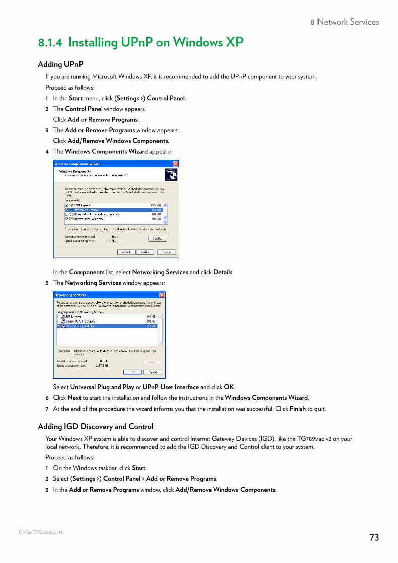
8 Network Services
DMS3-
8.1.4 Installing UPnP on Windows XPAdding UPnP
If you are running Microsoft Windows XP, it is recommended to add the UPnP component to your system.Proceed as follows:1 In the Start menu, click (Settings >) Control Panel.2 The Control Panel window appears.
Click Add or Remove Programs.3 The Add or Remove Programs window appears.
Click Add/Remove Windows Components.4 The Windows Components Wizard appears:
In the Components list, select Networking Services and click Details5 The Networking Services window appears:
Select Universal Plug and Play or UPnP User Interface and click OK.6 Click Next to start the installation and follow the instructions in the Windows Components Wizard.7 At the end of the procedure the wizard informs you that the installation was successful. Click Finish to quit.
Adding IGD Discovery and ControlYour Windows XP system is able to discover and control Internet Gateway Devices (IGD), like the TG789vac v2 on your local network. Therefore, it is recommended to add the IGD Discovery and Control client to your system.Proceed as follows:1 On the Windows taskbar, click Start.2 Select (Settings >) Control Panel > Add or Remove Programs.3 In the Add or Remove Programs window, click Add/Remove Windows Components.
73CTC-25-282 v1.0
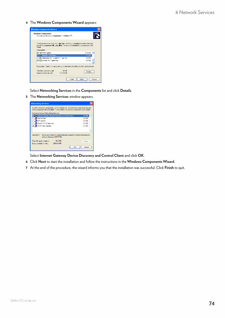
8 Network Services
DMS3-
4 The Windows Components Wizard appears:
Select Networking Services in the Components list and click Details.5 The Networking Services window appears:
Select Internet Gateway Device Discovery and Control Client and click OK.6 Click Next to start the installation and follow the instructions in the Windows Components Wizard.7 At the end of the procedure, the wizard informs you that the installation was successful. Click Finish to quit.
74CTC-25-282 v1.0
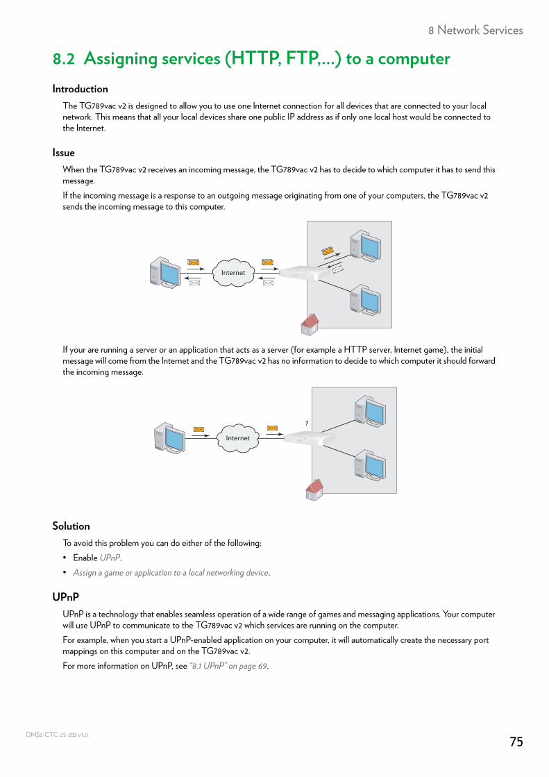
8 Network Services
DMS3-
8.2 Assigning services (HTTP, FTP,...) to a computerIntroduction
The TG789vac v2 is designed to allow you to use one Internet connection for all devices that are connected to your local network. This means that all your local devices share one public IP address as if only one local host would be connected to the Internet.
IssueWhen the TG789vac v2 receives an incoming message, the TG789vac v2 has to decide to which computer it has to send this message.If the incoming message is a response to an outgoing message originating from one of your computers, the TG789vac v2 sends the incoming message to this computer.
If your are running a server or an application that acts as a server (for example a HTTP server, Internet game), the initial message will come from the Internet and the TG789vac v2 has no information to decide to which computer it should forward the incoming message.
SolutionTo avoid this problem you can do either of the following:• Enable UPnP.• Assign a game or application to a local networking device.
UPnPUPnP is a technology that enables seamless operation of a wide range of games and messaging applications. Your computer will use UPnP to communicate to the TG789vac v2 which services are running on the computer.For example, when you start a UPnP-enabled application on your computer, it will automatically create the necessary port mappings on this computer and on the TG789vac v2.For more information on UPnP, see “8.1 UPnP” on page 69.
Internet
Internet
?
75CTC-25-282 v1.0
8 Network Services
DMS3-
Assign a game or application to a local networking deviceIf you assign a game or application to a local networking device, you will basically tell the TG789vac v2 that if it receives a request for a specific game or application, it needs to forward these messages to one specific computer.Proceed as follows:1 Browse to the TG789vac v2 GUI.
For more information, see “Accessing the TG789vac v2 GUI” on page 29.2 On the Toolbox menu, click Game & Application Sharing.3 In the Pick a task list, click Assign a game or application to a local network device.4 In the Game or application list, click the service you want to run on this specific computer. For example, HTTP Server
(World Wide Web).
5 In the Device list, select the computer to which you want to assign the service. 6 All incoming requests for the selected service will now be directed to the selected device. The TG789vac v2 will also
configure its firewall to allow this service.
Tips• You can assign multiple services to the same computer• You cannot assign the same service to multiple computers.• To reassign a service to another computer, you must first unassign the old rule and then create the new one.
If the service is not available in the list, click Create a new game or application in the Pick a task list.For more information, click Help on the TG789vac v2 GUI.
76CTC-25-282 v1.0
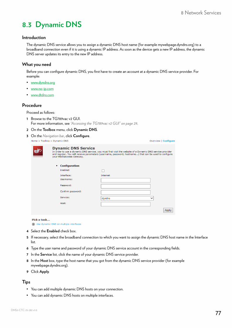
8 Network Services
DMS3-
8.3 Dynamic DNSIntroduction
The dynamic DNS service allows you to assign a dynamic DNS host name (for example mywebpage.dyndns.org) to a broadband connection even if it is using a dynamic IP address. As soon as the device gets a new IP address, the dynamic DNS server updates its entry to the new IP address.
What you needBefore you can configure dynamic DNS, you first have to create an account at a dynamic DNS service provider. For example:• www.dyndns.org• www.no-ip.com• www.dtdns.com
ProcedureProceed as follows: 1 Browse to the TG789vac v2 GUI.
For more information, see “Accessing the TG789vac v2 GUI” on page 29.2 On the Toolbox menu, click Dynamic DNS.3 On the Navigation bar, click Configure.
4 Select the Enabled check box.5 If necessary, select the broadband connection to which you want to assign the dynamic DNS host name in the Interface
list.6 Type the user name and password of your dynamic DNS service account in the corresponding fields.7 In the Service list, click the name of your dynamic DNS service provider.8 In the Host box, type the host name that you got from the dynamic DNS service provider (for example
mywebpage.dyndns.org).9 Click Apply.
Tips• You can add multiple dynamic DNS hosts on your connection.• You can add dynamic DNS hosts on multiple interfaces.
77CTC-25-282 v1.0
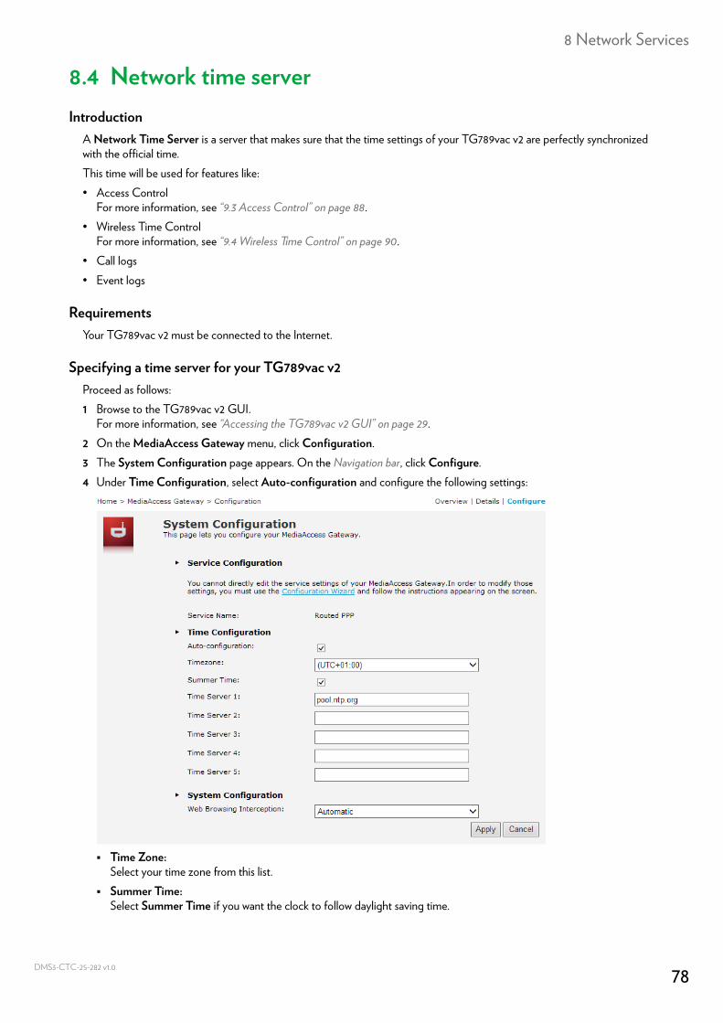
8 Network Services
DMS3-
8.4 Network time serverIntroduction
A Network Time Server is a server that makes sure that the time settings of your TG789vac v2 are perfectly synchronized with the official time.This time will be used for features like:• Access Control
For more information, see “9.3 Access Control” on page 88.• Wireless Time Control
For more information, see “9.4 Wireless Time Control” on page 90.• Call logs• Event logs
RequirementsYour TG789vac v2 must be connected to the Internet.
Specifying a time server for your TG789vac v2Proceed as follows:1 Browse to the TG789vac v2 GUI.
For more information, see “Accessing the TG789vac v2 GUI” on page 29.2 On the MediaAccess Gateway menu, click Configuration.3 The System Configuration page appears. On the Navigation bar, click Configure.4 Under Time Configuration, select Auto-configuration and configure the following settings:
Time Zone:Select your time zone from this list.
Summer Time:Select Summer Time if you want the clock to follow daylight saving time.
78CTC-25-282 v1.0
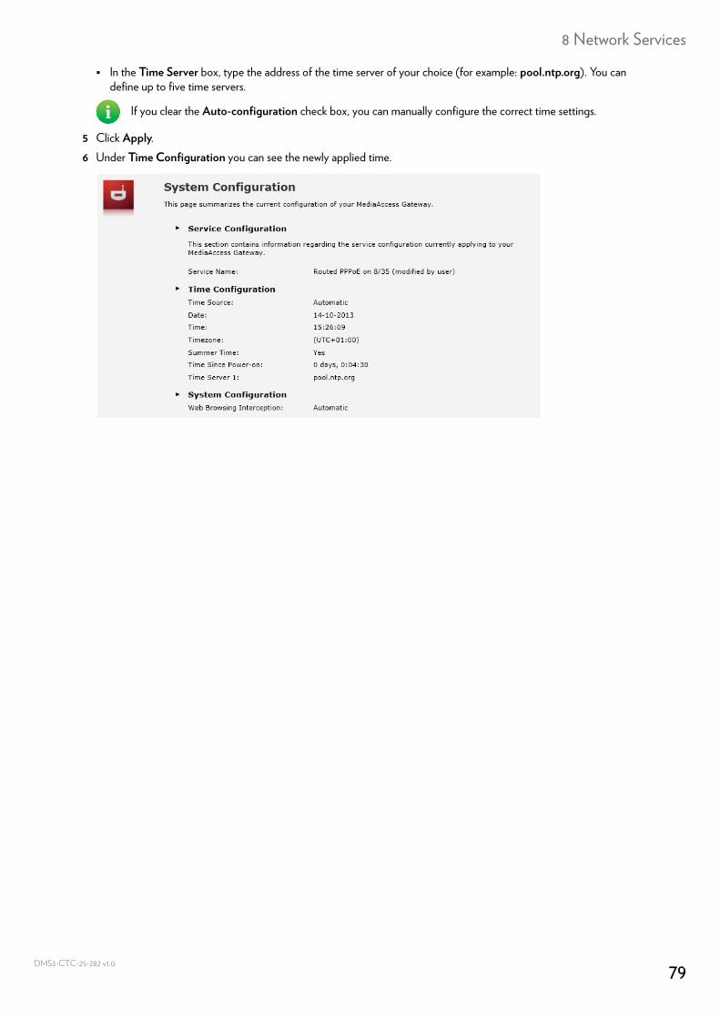
8 Network Services
DMS3-
In the Time Server box, type the address of the time server of your choice (for example: pool.ntp.org). You can define up to five time servers.
5 Click Apply.6 Under Time Configuration you can see the newly applied time.
If you clear the Auto-configuration check box, you can manually configure the correct time settings.
79CTC-25-282 v1.0
9 Internet security
DMS3-
9 Internet securityOverview
The TG789vac v2 offers various options to secure your network and network connection:
Topic Page
9.1 Parental Control 81
9.2 Firewall 86
9.3 Access Control 88
9.4 Wireless Time Control 90
80CTC-25-282 v1.0
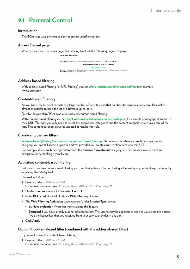
9 Internet security
DMS3-
9.1 Parental ControlIntroduction
The TG789vac v2 allows you to deny access to specific websites.
Access Denied pageWhen a user tries to access a page that is being blocked, the following page is displayed:
Address-based filteringWith address-based filtering (or URL-filtering) you can block websites based on their address (for example www.porn.com).
Content-based filteringAs you know, the Internet consists of a large number of websites, and that number still increases every day. This makes it almost impossible to keep the list of addresses up-to-date.To solve this problem TG789vac v2 introduced content-based filtering.With content-based filtering you can block websites based on their content category (for example pornography) instead of their URL. This way, you only need to select the appropriate categories and the content category server takes care of the rest. This content category server is updated at regular intervals.
Combining the two filtersAddress-based filtering has priority over content-based filtering. This means that when you are blocking a specific category, you can still access a specific address provided you create a rule to allow access to that URL.For example, if you are blocking content from the Finance / Investment category, you can create a rule to make an exception for netbanking.mybank.com.
Activating content-based filteringBefore you can use content-based filtering you must first activate it by purchasing a license key at your service provider or by activating the 30-day trial.Proceed as follows:1 Browse to the TG789vac v2 GUI.
For more information, see “Accessing the TG789vac v2 GUI” on page 29.2 On the Toolbox menu, click Parental Control.3 In the Pick a task list, click Activate Web Filtering License.4 The Web Filtering Activation page appears. Under License Type, select: 30-days evaluation if you first want evaluate this feature. Standard if you have already purchased a license key. The License key box appears as soon as you select this option.
Type the license key that you received from your service provider in this box.5 Click Apply.
Option 1: content-based filter (combined with the address-based filter)If you want to use the content-based filtering:1 Browse to the TG789vac v2 GUI.
For more information, see “Accessing the TG789vac v2 GUI” on page 29.
81CTC-25-282 v1.0
9 Internet security
DMS3-
2 On the Toolbox menu, click Parental Control.3 On the Navigation bar, click Configure.4 Make sure that the Use Content-Based Filter check box is selected.5 Configure the content-based filter. For more information, see “9.1.1 Configuring content-based filtering” on page 83.6 If you want to make exceptions for specific websites, add the necessary rules in the address-based filter. For more
information, see “9.1.2 Adding rules for address-based filtering” on page 84.
Option 2: address-based filter onlyTake this option if content filtering is not available on your TG789vac v2 or you don’t want to use it.To configure address-based filtering:1 Browse to the TG789vac v2 GUI.
For more information, see “Accessing the TG789vac v2 GUI” on page 29.2 On the Toolbox menu, click Parental Control.3 On the Navigation bar, click Configure.4 Make sure that the Use Address-Based Filter check box is selected.5 In the Action for Unknown Sites, select: Allow as the default rule if you want to allow access to all websites and manually specify which websites may not be
accessed. Block as the default rule if you want to deny access to all websites and manually specify a number of websites that may
be accessed.6 Click Apply.7 If you want to make exceptions for specific websites, add the necessary rules in the address-based filter.
For more information, see “9.1.2 Adding rules for address-based filtering” on page 84.
82CTC-25-282 v1.0
9 Internet security
DMS3-
9.1.1 Configuring content-based filteringRequirements
Content-based filtering must be activated on your TG789vac v2.For more information, see “Activating content-based filtering” on page 81.
Accessing the configuration pageProceed as follows:1 Browse to the TG789vac v2 GUI.
For more information, see “Accessing the TG789vac v2 GUI” on page 29.2 On the Toolbox menu, click Parental Control.3 On the Navigation bar, click Configure.4 Under Content-Based Filtering you can change the settings of the content-based filter.
ConfigurationUnder Content-Based Filtering:1 Select Use Content-Based Filter check box (if needed).2 In the Action for uncategorised sites list, select a default action for sites that have not yet been categorised.3 Under Content Level, select the content level you want to use.
If you want a more detailed view of the content that will be blocked for this level, click the Edit link next to the content level.If needed, you can change the Name, Description and Configuration of the content level.
4 Click Apply after you have made your changes.
Creating your own content levelProceed as follows:1 In the Pick a task list, click Create a new content level.2 Enter a Name and Description for your content level and click Next.3 Under Configuration, select: Clone Existing Level if you want to start from an existing level. You can now select the level that you want to clone. White list if you want to block everything and select which content should be allowed. Black list if you want to allow everything and select which content should be blocked.Click Next.
4 Under Configuration: Select the check boxes of the categories/groups you want to allow. Clear the check boxes of the categories/groups you want to block.
5 Click Apply.6 Configure the content-based filter with the new level. For more information, see “Configuration” on page 83.
83CTC-25-282 v1.0
9 Internet security
DMS3-
9.1.2 Adding rules for address-based filteringIntroduction
Address-based filtering has a higher priority than content-based filtering. This means that when you are blocking a specific category, you can still access a specific site if you allow it in the address-based filter.ExampleIf you block content from the Finance / Investment category and allow access to netbanking.mybank.com, netbanking.mybank.com will still be accessible.
OptionsWith the address-based filter you can:• Deny access to a specific website.• Allow access to a specific website.• Redirect a website.• Redirect all websites.
Deny access to a specific websiteProceed as follows:1 Browse to the TG789vac v2 GUI.
For more information, see “Accessing the TG789vac v2 GUI” on page 29.2 On the Toolbox menu, click Parental Control.3 Make sure the Use Address-Based Filter check box is selected.4 Type the URL of the website you want to block (for example “mail.provider.com”) in the Web Site box.5 In the Action list, click Block.6 Click Add.
Allow access to a specific websiteProceed as follows:1 Browse to the TG789vac v2 GUI.
For more information, see “Accessing the TG789vac v2 GUI” on page 29.2 On the Toolbox menu, click Parental Control.3 Make sure the Use Address-Based Filter check box is selected.4 Type the URL of the website you want to allow (for example “netbanking.bank.com”) in the Web Site box.5 In the Action list, click Allow.6 Click Add.
Redirect a websiteProceed as follows:1 Browse to the TG789vac v2 GUI.
For more information, see “Accessing the TG789vac v2 GUI” on page 29.2 On the Toolbox menu, click Parental Control.3 Make sure the Use Address-Based Filter check box is selected.4 Type the URL of the website you want to redirect (for example “cracks.am”) in the Web Site box.5 Click Redirect in the Action list.6 Type the URL of the website you want to redirect to (for example “mycompany.com/internetpolicy.htm”) in the Redirect
box.
84CTC-25-282 v1.0

9 Internet security
DMS3-
7 Click Add.
Redirect all websitesProceed as follows:1 Browse to the TG789vac v2 GUI.
For more information, see “Accessing the TG789vac v2 GUI” on page 29.2 On the Toolbox menu, click Parental Control.3 Make sure the Use Address-Based Filter check box is selected.4 Type “*” in the Web Site box.5 Click Redirect in the Action list.6 Type the URL of the website you want to redirect to (for example “mycompany.com/internetpolicy.htm”) in the Redirect
box.7 Click Add.
85CTC-25-282 v1.0
9 Internet security
DMS3-
9.2 FirewallIntroduction
The TG789vac v2 comes with an integrated firewall that helps you protect your network from attacks from the Internet. This firewall has a number of predefined levels to allow you to adjusted the firewall to your needs.
Predefined security levelsThe TG789vac v2 has a number of predefined security levels. The following levels are available:• BlockAll:
All traffic from and to the Internet is blocked. Game and Application Sharing is not allowed by the firewall.
• Standard: All outgoing connections are allowed. All incoming connections are blocked, except for inbound connections assigned to a local host via Game and Application Sharing. This is the default firewall level.
• Disabled: All in- and outgoing traffic is allowed to pass through your TG789vac v2, including Game and Application Sharing.
Changing the security levelProceed as follows:1 Browse to the TG789vac v2 GUI.
For more information, see “Accessing the TG789vac v2 GUI” on page 29.2 On the Toolbox menu, click Firewall.3 The Firewall page appears. In the upper-right corner, click Configure.4 Under Security Settings, select the security level of your choice and click Apply.
Creating your own security levelProceed as follows:1 In the Toolbox menu click Firewall.2 In the Firewall section, go to the Configure page.3 In the Pick a task list, click Create a new Security Level.4 In the Name box, type a name for the new security level and select an existing security level to clone from.5 Click Apply.
6 A page with the firewall settings of your newly created security level appears. Click Edit.7 Enter the following information: The Name of the firewall rule. The Source Interface and IP Address (range).
Or you can type a User-defined IP address (range).
Although BlockAll will block all connections, some mandatory types of traffic such as DNS will still be relayed between LAN and WAN by the TG789vac v2.
The firewall levels only have impact on traffic passing through your TG789vac v2. This means that the handling of traffic directly appointed from and to TG789vac v2 is independent of the selected firewall level.
Protocol checks will be performed on all accepted connections, irrespective of the chosen level.
Once you create a security level, you can not delete it anymore. It will always available in the list of available security levels.
Use Any as IP address in case all traffic for the interface should be parsed.
86CTC-25-282 v1.0

9 Internet security
DMS3-
The Destination Interface and IP Address (range)
Or you can type a User-defined IP address (range). The Service type of the traffic; this can be a protocol (DNS, SMTP,...) or a specific TG789vac v2 system service.
8 Select an Action that should be done on traffic for which the firewall rules applies: Accept: to allow the traffic to pass Deny: to drop the traffic (without notification) Count: to let the traffic pass, but count it (Hits)
9 Click Apply.
Use Any as IP address in case all traffic for the interface should be parsed.
87CTC-25-282 v1.0
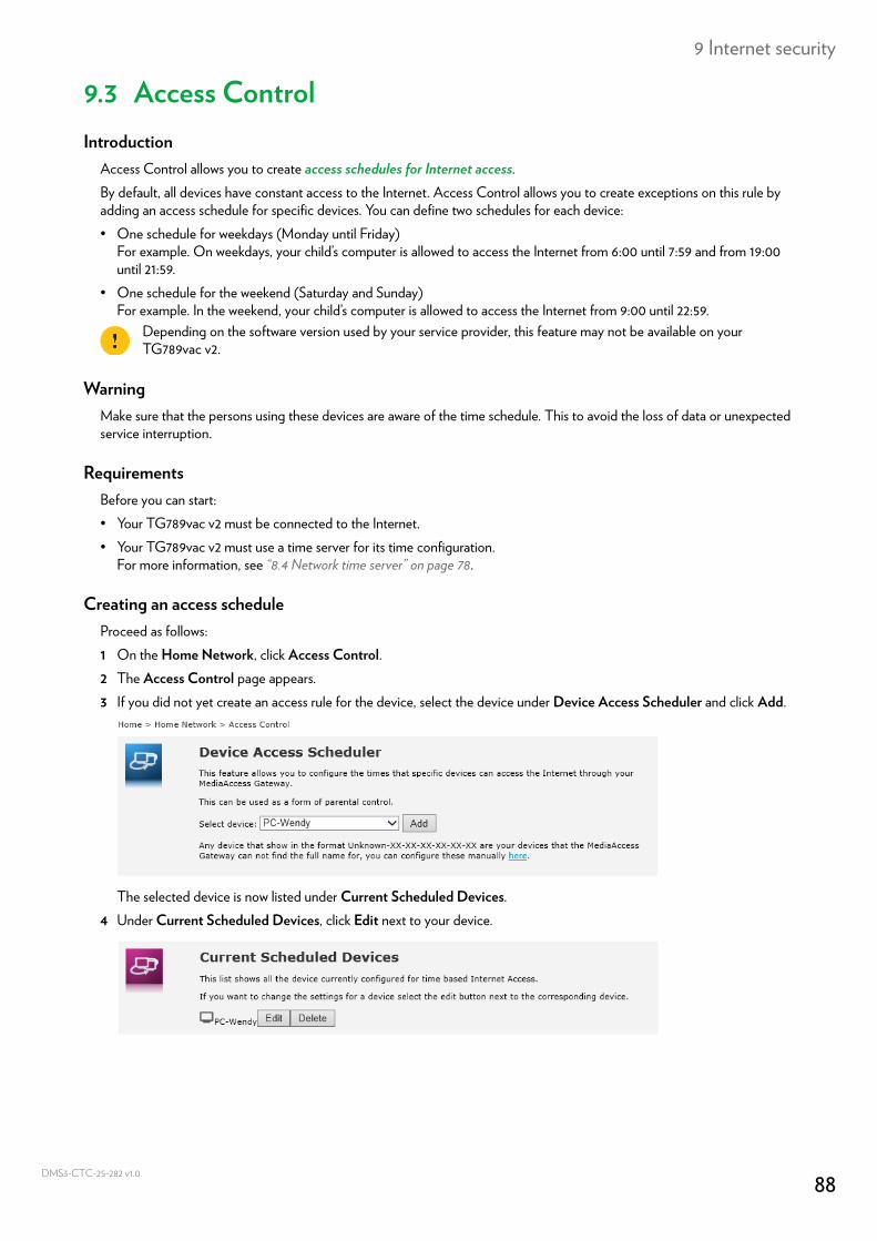
9 Internet security
DMS3-
9.3 Access ControlIntroduction
Access Control allows you to create access schedules for Internet access.By default, all devices have constant access to the Internet. Access Control allows you to create exceptions on this rule by adding an access schedule for specific devices. You can define two schedules for each device:• One schedule for weekdays (Monday until Friday)
For example. On weekdays, your child’s computer is allowed to access the Internet from 6:00 until 7:59 and from 19:00 until 21:59.
• One schedule for the weekend (Saturday and Sunday)For example. In the weekend, your child’s computer is allowed to access the Internet from 9:00 until 22:59.
WarningMake sure that the persons using these devices are aware of the time schedule. This to avoid the loss of data or unexpected service interruption.
RequirementsBefore you can start:• Your TG789vac v2 must be connected to the Internet.• Your TG789vac v2 must use a time server for its time configuration.
For more information, see “8.4 Network time server” on page 78.
Creating an access scheduleProceed as follows:1 On the Home Network, click Access Control.2 The Access Control page appears.3 If you did not yet create an access rule for the device, select the device under Device Access Scheduler and click Add.
The selected device is now listed under Current Scheduled Devices.4 Under Current Scheduled Devices, click Edit next to your device.
Depending on the software version used by your service provider, this feature may not be available on your TG789vac v2.
88CTC-25-282 v1.0
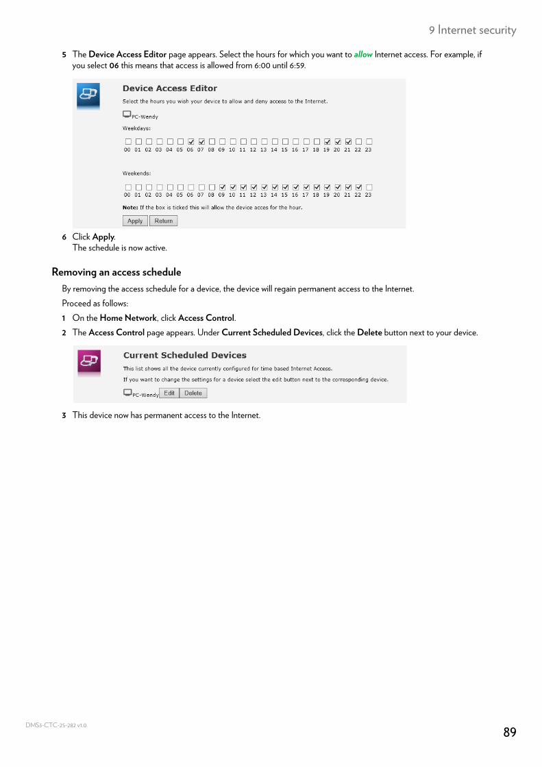
9 Internet security
DMS3-
5 The Device Access Editor page appears. Select the hours for which you want to allow Internet access. For example, if you select 06 this means that access is allowed from 6:00 until 6:59.
6 Click Apply.The schedule is now active.
Removing an access scheduleBy removing the access schedule for a device, the device will regain permanent access to the Internet.Proceed as follows:1 On the Home Network, click Access Control.2 The Access Control page appears. Under Current Scheduled Devices, click the Delete button next to your device.
3 This device now has permanent access to the Internet.
89CTC-25-282 v1.0
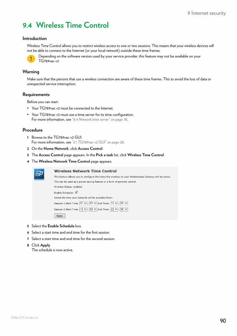
9 Internet security
DMS3-
9.4 Wireless Time ControlIntroduction
Wireless Time Control allows you to restrict wireless access to one or two sessions. This means that your wireless devices will not be able to connect to the Internet (or your local network) outside these time frames.
WarningMake sure that the persons that use a wireless connection are aware of these time frames. This to avoid the loss of data or unexpected service interruption.
RequirementsBefore you can start:• Your TG789vac v2 must be connected to the Internet.• Your TG789vac v2 must use a time server for its time configuration.
For more information, see “8.4 Network time server” on page 78.
Procedure1 Browse to the TG789vac v2 GUI.
For more information, see “3.1 TG789vac v2 GUI” on page 28.2 On the Home Network, click Access Control.3 The Access Control page appears. In the Pick a task list, click Wireless Time Control.4 The Wireless Network Time Control page appears.
5 Select the Enable Schedule box.6 Select a start time and end time for the first session.7 Select a start time and end time for the second session.8 Click Apply.
The schedule is now active.
Depending on the software version used by your service provider, this feature may not be available on your TG789vac v2.
90CTC-25-282 v1.0
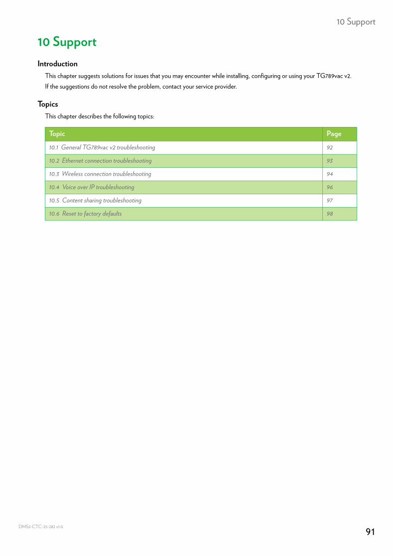
10 Support
DMS3-
10 SupportIntroduction
This chapter suggests solutions for issues that you may encounter while installing, configuring or using your TG789vac v2.If the suggestions do not resolve the problem, contact your service provider.
TopicsThis chapter describes the following topics:
Topic Page
10.1 General TG789vac v2 troubleshooting 92
10.2 Ethernet connection troubleshooting 93
10.3 Wireless connection troubleshooting 94
10.4 Voice over IP troubleshooting 96
10.5 Content sharing troubleshooting 97
10.6 Reset to factory defaults 98
91CTC-25-282 v1.0
10 Support
DMS3-
10.1 General TG789vac v2 troubleshootingNone of the LEDs light up (TG789vac v2 does not work)
Make sure that:• The TG789vac v2 is plugged into a power socket outlet.• You are using the correct power supply for your TG789vac v2 device.
• The TG789vac v2 is turned on via the push button or rocker switch on the back panel.
The Broadband LED does not light up or is blinkingMake sure that:• The DSL cable is correctly connected. For more information, see “2.1 Connecting the TG789vac v2 to your service
provider’s network”.• The DSL service is enabled on your telephone line. For more information, contact your Internet Service Provider.
The Internet LED does not light upIf you must authenticate to connect to the Internet, make sure that your user name and password are correct.Proceed as follows:1 Browse to the TG789vac v2 GUI.
For more information, see “Accessing the TG789vac v2 GUI” on page 29.2 On the Broadband menu, click Internet Services.3 Under Internet, click View More.4 Check your user name 5 Re-enter your password.6 Click Connect.
TG789vac v2 unreachableIf you can not access your TG789vac v2 via your web browser or the Setup wizard, you might consider a hardware reset as described in “10.6 Reset to factory defaults” on page 98.
The power requirements for your TG789vac v2 are clearly indicated on the identification label of the TG789vac v2. Only use the power adaptor supplied with your TG789vac v2.
92CTC-25-282 v1.0
10 Support
DMS3-
10.2 Ethernet connection troubleshootingEthernet LED does not light up
Make sure that:• The Ethernet cable is correctly connected to the Ethernet port on your TG789vac v2 and your computer.• You are using the correct cable type for your Ethernet equipment, that is at least UTP CAT5 with RJ-45 connectors.
For the Gigabit Ethernet ports you need at least CAT5E, but it is recommended to use CAT6.
93CTC-25-282 v1.0
10 Support
DMS3-
10.3 Wireless connection troubleshootingThe TG789vac v2 does not appear in your wireless client’s access point list
• Make sure that the TG789vac v2 access point is enabled and that the network name is broadcasted.a Browse to the TG789vac v2 GUI.
For more information, see “Accessing the TG789vac v2 GUI” on page 29.b On the left menu, click Home Network.c The Home Network page appears, Under Wireless. click:
• WLAN to view the settings of the 2.4 GHz access point.
• WLAN_5G to view the settings of the 5 GHz access point.
d The Wireless Access Point page appears.e In the Navigation bar, click Configure.f Under Configuration, select WLAN Enabled and Interface Enabled.g Under Security, select Broadcast Network Name.h Click Apply.
• If the signal is low or not available, try to reposition the TG789vac v2 or (if available) redirect the antenna(s) of the TG789vac v2 for optimal performance.
• Change the wireless channel.
The TG789vac v2 access point no longer availableIf you were able to connect in the past, but can’t connect anymore:• Make sure that the wireless client adapter is enabled (message like “radio on”).• Make sure that the wireless client is still using the correct wireless settings (network name (SSID), security settings).
Poor Wireless Connectivity or RangeTry the following:• Check the signal strength, indicated by the wireless client manager. If the signal is low, try to reposition the TG789vac v2
or (if available) redirect the antenna(s) of the TG789vac v2 for optimal performance.• Change the wireless channel.• Use WPA(2)-PSK as encryption.
For more information, see “4.4 Securing your wireless connection” on page 40.
Change the wireless channelProceed as follows:1 Browse to the TG789vac v2 GUI.
For more information, see “Accessing the TG789vac v2 GUI” on page 29.2 On the left menu, click Home Network.3 The Home Network page appears, Under Wireless. click:
94CTC-25-282 v1.0
10 Support
DMS3-
WLAN to view the settings of the 2.4 GHz access point.
WLAN_5G to view the settings of the 5 GHz access point.
4 In the Navigation bar, click Configure.5 Under Configuration, select Manual in the Channel Selection list and then select the channel of your choice in the
Channel list.6 Click Apply.
Can not connect via WPSIf you are having trouble connecting your wireless client via WPS, try to configure it manually. For more information, see “4.2 Connecting your wireless client without WPS” on page 38.
95CTC-25-282 v1.0

10 Support
DMS3-
10.4 Voice over IP troubleshootingIntroduction
If you cannot make or receive any phone calls via your TG789vac v2, try the suggested solutions in this section.
Calling over VoIPIf you have problems calling via VoIP, check whether:• Your phone is correctly connected to the TG789vac v2.• Your phone number, user name, and password are configured correctly.• The registrar’s and proxy server’s IP address and port number are configured correctly.• The Power, Broadband and Voice LEDs are on.
96CTC-25-282 v1.0
10 Support
DMS3-
10.5 Content sharing troubleshootingGetting the IP address of your USB storage device
The TG789vac v2 always uses the highest available address in your DHCP pool. When using the default settings this should be 192.168.1.253.You can check the IP address as follows:1 Browse to the TG789vac v2 GUI.
For more information, see “Accessing the TG789vac v2 GUI” on page 29.2 On the Toolbox menu, click Content Sharing.3 Under IP configuration, you can find the IP address to use.
97CTC-25-282 v1.0
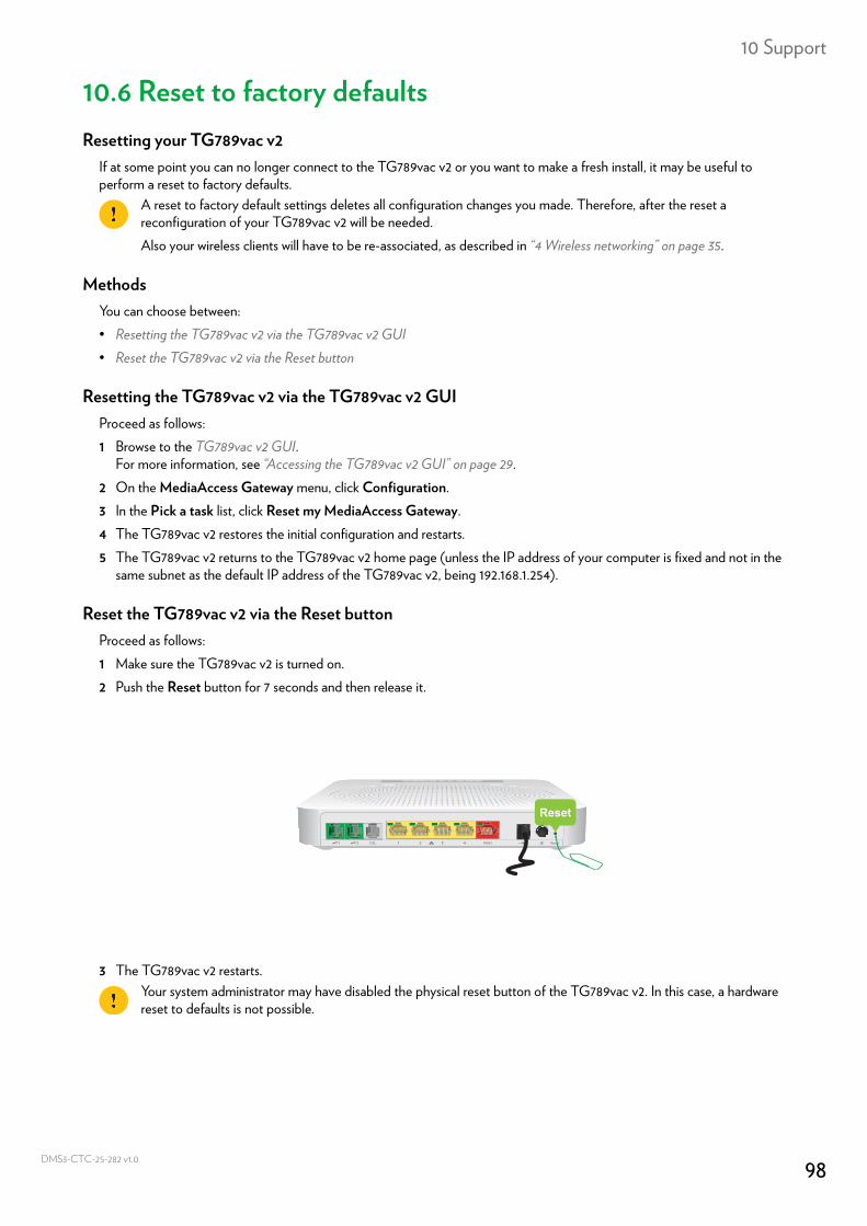
10 Support
DMS3-
10.6 Reset to factory defaultsResetting your TG789vac v2
If at some point you can no longer connect to the TG789vac v2 or you want to make a fresh install, it may be useful to perform a reset to factory defaults.
MethodsYou can choose between:• Resetting the TG789vac v2 via the TG789vac v2 GUI• Reset the TG789vac v2 via the Reset button
Resetting the TG789vac v2 via the TG789vac v2 GUIProceed as follows:1 Browse to the TG789vac v2 GUI.
For more information, see “Accessing the TG789vac v2 GUI” on page 29.2 On the MediaAccess Gateway menu, click Configuration.3 In the Pick a task list, click Reset my MediaAccess Gateway.4 The TG789vac v2 restores the initial configuration and restarts.5 The TG789vac v2 returns to the TG789vac v2 home page (unless the IP address of your computer is fixed and not in the
same subnet as the default IP address of the TG789vac v2, being 192.168.1.254).
Reset the TG789vac v2 via the Reset buttonProceed as follows:1 Make sure the TG789vac v2 is turned on.2 Push the Reset button for 7 seconds and then release it.
3 The TG789vac v2 restarts.
A reset to factory default settings deletes all configuration changes you made. Therefore, after the reset a reconfiguration of your TG789vac v2 will be needed.Also your wireless clients will have to be re-associated, as described in “4 Wireless networking” on page 35.
Your system administrator may have disabled the physical reset button of the TG789vac v2. In this case, a hardware reset to defaults is not possible.
Reset
98CTC-25-282 v1.0

Copyright ©2016 Technicolor. All rights reserved. DMS3-CTC-25-282 v1.0.All tradenames referenced are service marks, trademarks, or registered trademarks of their respective companies.Specifications subject to change without notice.
TECHNICOLOR1-5 rue Jeanne d’Arc92130 Issy les MoulineauxFrancewww.technicolor.com