Embed Size (px)
Citation preview
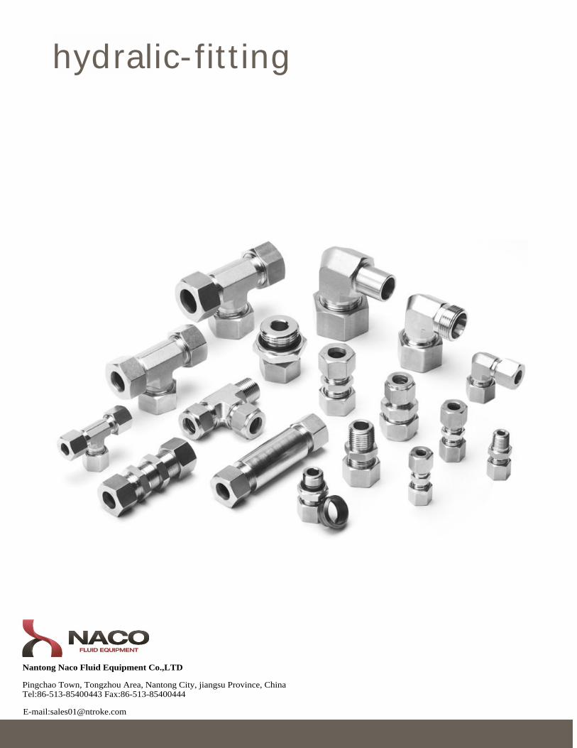
hydralic-fitting
Nantong Naco Fluid Equipment Co.,LTD
Pingchao Town, Tongzhou Area, Nantong City, jiangsu Province, ChinaTel:86-513-85400443 Fax:86-513-85400444
E-mail:[email protected]
H2
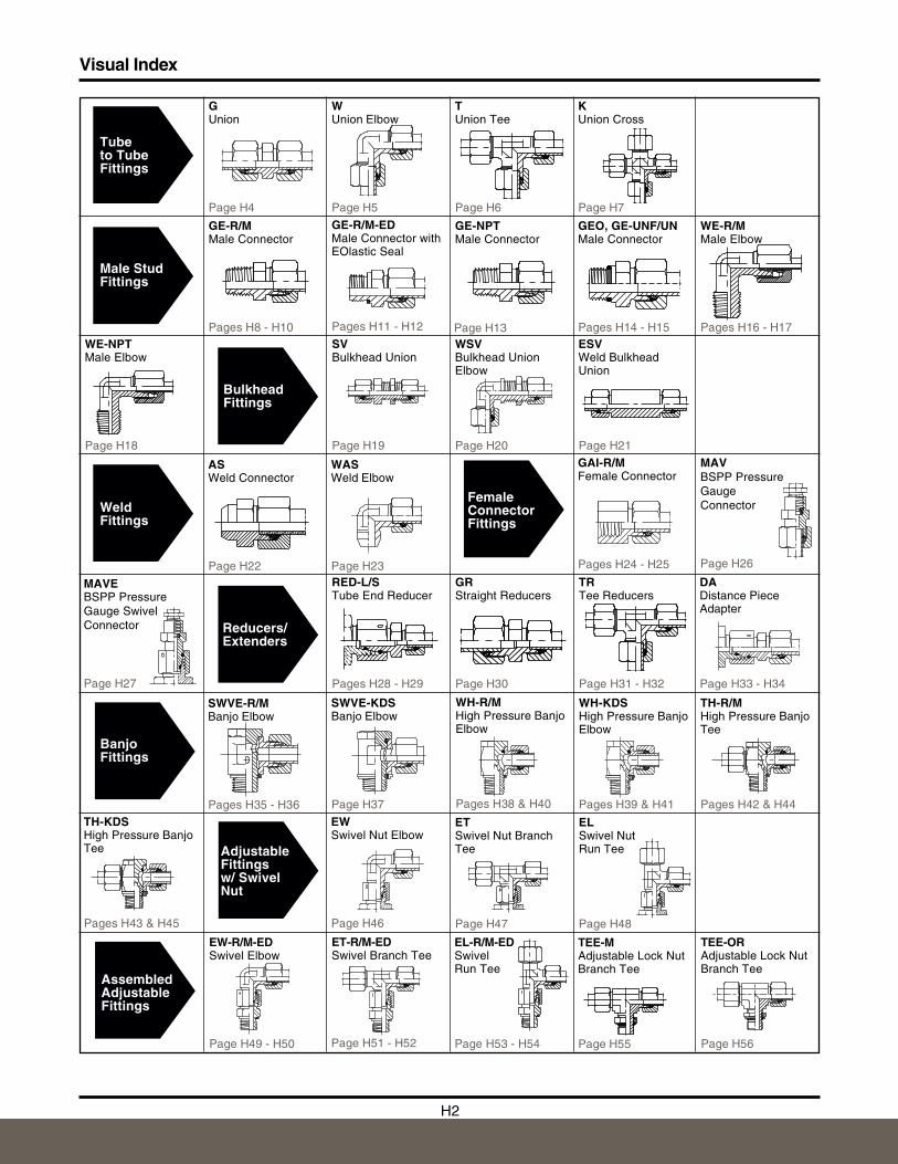
GUnion
Page H4
WUnion Elbow
Page H5
TUnion Tee
Page H6
KUnion Cross
Page H7
GE-R/MMale Connector
Pages H8 - H10
GE-R/M-EDMale Connector withEOlastic Seal
Pages H11 - H12
GE-NPTMale Connector
Page H13
GEO, GE-UNF/UNMale Connector
Pages H14 - H15
WE-R/MMale Elbow
Pages H16 - H17
BulkheadFittings
SVBulkhead Union
Page H19
WSVBulkhead UnionElbow
Page H20
ESVWeld BulkheadUnion
Page H21
WE-NPTMale Elbow
Page H18
FemaleConnectorFittings
WeldFittings
MAVEBSPP PressureGauge SwivelConnector
Page H27
ASWeld Connector
Page H22RED-L/STube End Reducer
Pages H28 - H29
MAVBSPP PressureGaugeConnector
Page H26
GAI-R/MFemale Connector
Pages H24 - H25
GRStraight Reducers
Page H30
TRTee Reducers
Page H31 - H32
BanjoFittings
SWVE-R/MBanjo Elbow
Pages H35 - H36
WH-R/MHigh Pressure BanjoElbow
Pages H38 & H40
TH-R/MHigh Pressure BanjoTee
Pages H42 & H44
Male StudFittings
Tubeto TubeFittings
Reducers/Extenders
Visual Index
SWVE-KDSBanjo Elbow
Page H37
WH-KDSHigh Pressure BanjoElbow
Pages H39 & H41
TH-KDSHigh Pressure BanjoTee
Pages H43 & H45
WASWeld Elbow
Page H23
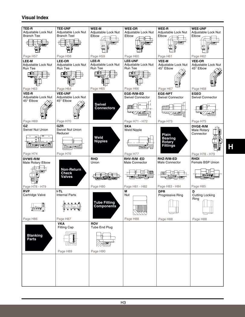
AdjustableFittingsw/ SwivelNut
EWSwivel Nut Elbow
Page H46
ETSwivel Nut BranchTee
Page H47
ELSwivel NutRun Tee
Page H48
AssembledAdjustableFittings
EW-R/M-EDSwivel Elbow
Page H49 - H50
ET-R/M-EDSwivel Branch Tee
Page H51 - H52
EL-R/M-EDSwivelRun Tee
Page H53 - H54
TEE-MAdjustable Lock NutBranch Tee
Page H55
TEE-ORAdjustable Lock NutBranch Tee
Page H56
DADistance PieceAdapter
Page H33 - H34
H3
H
DVGE-R/MMale RotaryConnector
Page H78 - H79
DVWE-R/MMale Rotary Elbow
Page H78 - H79
PlainBearingRotaryFittings
SwivelConnectors
GZSwivel Nut Union
Page H74
EGE-R/M-EDSwivel Connector
Page H71 - H72
WeldNipples
SKAWeld Nipple
Page H77
GZRSwivel Nut UnionReducer
Page H76
EGE-NPTSwivel Connector
Page H73
WEE-MAdjustable Lock NutElbow
Page H59
WEE-ORAdjustable Lock NutElbow
Page H60
WEE-RAdjustable Lock NutElbow
Page H61
WEE-UNFAdjustable Lock NutElbow
Page H62
LEE-MAdjustable Lock NutRun Tee
Page H63
LEE-ORAdjustable Lock NutRun Tee
Page H64
LEE-RAdjustable Lock NutRun Tee
Page H65
LEE-UNFAdjustable Lock NutRun Tee
Page H66
VEE-MAdjustable Lock Nut45° Elbow
Page H67
VEE-ORAdjustable Lock Nut45° Elbow
Page H68
TEE-RAdjustable Lock NutBranch Tee
Page H57
TEE-UNFAdjustable Lock NutBranch Teel
Page H58
VEE-RAdjustable Lock Nut45° Elbow
Page H69
VEE-UNFAdjustable Lock Nut45° Elbow
Page H70
EGEOSwivel Connector
Page H75
Visual Index
RHV-R/M -EDMale Connector
Page H81 - H82
RHDUnion
Page H80
Non-ReturnCheckValves
RHDIFemale BSP Union
Page H85
RHZ-R/M-EDMale Connector
Page H83 - H84
MNut
Page H88
Tube FittingComponents
RVPCartridge Valve
Page H86
I-TLInternal Parts
Page H87
DPRProgressive Ring
Page H88
DCutting LockingRing
Page H88
BlankingParts
VKAFitting Cap
Page H89
ROVTube End Plug
Page H90
H4
Part Data
H
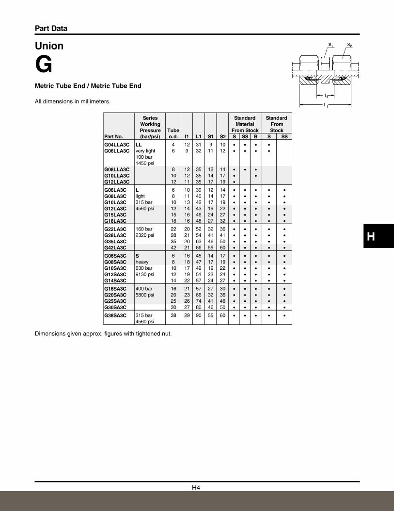
Union
GMetric Tube End / Metric Tube End
All dimensions in millimeters.
Dimensions given approx. figures with tightened nut.
Series Standard StandardWorking Material FromPressure Tube From Stock Stock
Part No. (bar/psi) o.d. I1 L1 S1 S2 S SS B S SS
G04LLA3C LL 4 12 31 9 10 • • • •G06LLA3C very light 6 9 32 11 12 • • • •
100 bar1450 psi
G08LLA3C 8 12 35 12 14 • • •G10LLA3C 10 12 35 14 17 • •G12LLA3C 12 11 35 17 19 •
G06LA3C L 6 10 39 12 14 • • • • •G08LA3C light 8 11 40 14 17 • • • • •G10LA3C 315 bar 10 13 42 17 19 • • • • •G12LA3C 4560 psi 12 14 43 19 22 • • • • •G15LA3C 15 16 46 24 27 • • • • •G18LA3C 18 16 48 27 32 • • • • •
G22LA3C 160 bar 22 20 52 32 36 • • • • •G28LA3C 2320 psi 28 21 54 41 41 • • • • •G35LA3C 35 20 63 46 50 • • • • •G42LA3C 42 21 66 55 60 • • • • •
G06SA3C S 6 16 45 14 17 • • • • •G08SA3C heavy 8 18 47 17 19 • • • • •G10SA3C 630 bar 10 17 49 19 22 • • • • •G12SA3C 9130 psi 12 19 51 22 24 • • • • •G14SA3C 14 22 57 24 27 • • • • •
G16SA3C 400 bar 16 21 57 27 30 • • • • •G20SA3C 5800 psi 20 23 66 32 36 • • • • •G25SA3C 25 26 74 41 46 • • • • •G30SA3C 30 27 80 46 50 • • • • •
G38SA3C 315 bar 38 29 90 55 60 • • • • •4560 psi
H5
Part Data
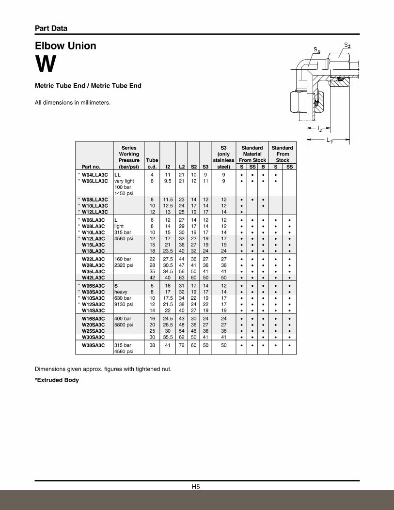
Elbow Union
WMetric Tube End / Metric Tube End
All dimensions in millimeters.
Dimensions given approx. figures with tightened nut.
*Extruded Body
Series S3 Standard StandardWorking (only Material FromPressure Tube stainless From Stock Stock
Part no. (bar/psi) o.d. I2 L2 S2 S3 steel) S SS B S SS
* W04LLA3C LL 4 11 21 10 9 9 • • • •* W06LLA3C very light 6 9.5 21 12 11 9 • • • •
100 bar1450 psi
* W08LLA3C 8 11.5 23 14 12 12 • • •* W10LLA3C 10 12.5 24 17 14 12 • •* W12LLA3C 12 13 25 19 17 14 •* W06LA3C L 6 12 27 14 12 12 • • • • •* W08LA3C light 8 14 29 17 14 12 • • • • •* W10LA3C 315 bar 10 15 30 19 17 14 • • • • •* W12LA3C 4560 psi 12 17 32 22 19 17 • • • • •
W15LA3C 15 21 36 27 19 19 • • • • •W18LA3C 18 23.5 40 32 24 24 • • • • •
W22LA3C 160 bar 22 27.5 44 36 27 27 • • • • •W28LA3C 2320 psi 28 30.5 47 41 36 36 • • • • •W35LA3C 35 34.5 56 50 41 41 • • • • •W42LA3C 42 40 63 60 50 50 • • • • •
* W06SA3C S 6 16 31 17 14 12 • • • • •* W08SA3C heavy 8 17 32 19 17 14 • • • • •* W10SA3C 630 bar 10 17.5 34 22 19 17 • • • • •* W12SA3C 9130 psi 12 21.5 38 24 22 17 • • • • •
W14SA3C 14 22 40 27 19 19 • • • • •
W16SA3C 400 bar 16 24.5 43 30 24 24 • • • • •W20SA3C 5800 psi 20 26.5 48 36 27 27 • • • • •W25SA3C 25 30 54 46 36 36 • • • • •W30SA3C 30 35.5 62 50 41 41 • • • • •
W38SA3C 315 bar 38 41 72 60 50 50 • • • • •4560 psi
H6
Part Data
H
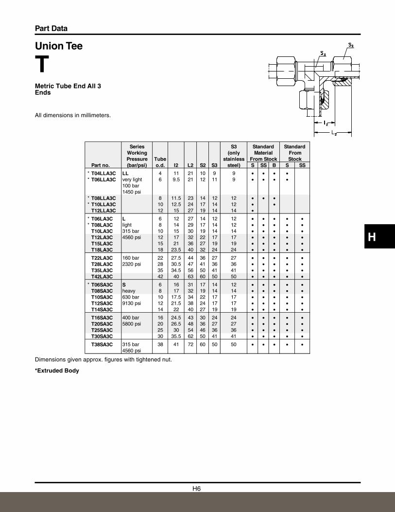
Union Tee
TMetric Tube End All 3 Ends
All dimensions in millimeters.
Dimensions given approx. figures with tightened nut.
*Extruded Body
Series S3 Standard StandardWorking (only Material FromPressure Tube stainless From Stock Stock
Part no. (bar/psi) o.d. I2 L2 S2 S3 steel) S SS B S SS
* T04LLA3C LL 4 11 21 10 9 9 • • • •* T06LLA3C very light 6 9.5 21 12 11 9 • • • •
100 bar1450 psi
* T08LLA3C 8 11.5 23 14 12 12 • • •* T10LLA3C 10 12.5 24 17 14 12 • •
T12LLA3C 12 15 27 19 14 14 •* T06LA3C L 6 12 27 14 12 12 • • • • •* T08LA3C light 8 14 29 17 14 12 • • • • •
T10LA3C 315 bar 10 15 30 19 14 14 • • • • •T12LA3C 4560 psi 12 17 32 22 17 17 • • • • •T15LA3C 15 21 36 27 19 19 • • • • •T18LA3C 18 23.5 40 32 24 24 • • • • •
T22LA3C 160 bar 22 27.5 44 36 27 27 • • • • •T28LA3C 2320 psi 28 30.5 47 41 36 36 • • • • •T35LA3C 35 34.5 56 50 41 41 • • • • •T42LA3C 42 40 63 60 50 50 • • • • •
* T06SA3C S 6 16 31 17 14 12 • • • • •T08SA3C heavy 8 17 32 19 14 14 • • • • •T10SA3C 630 bar 10 17.5 34 22 17 17 • • • • •T12SA3C 9130 psi 12 21.5 38 24 17 17 • • • • •T14SA3C 14 22 40 27 19 19 • • • • •
T16SA3C 400 bar 16 24.5 43 30 24 24 • • • • •T20SA3C 5800 psi 20 26.5 48 36 27 27 • • • • •T25SA3C 25 30 54 46 36 36 • • • • •T30SA3C 30 35.5 62 50 41 41 • • • • •
T38SA3C 315 bar 38 41 72 60 50 50 • • • • •4560 psi
H7
Part Data
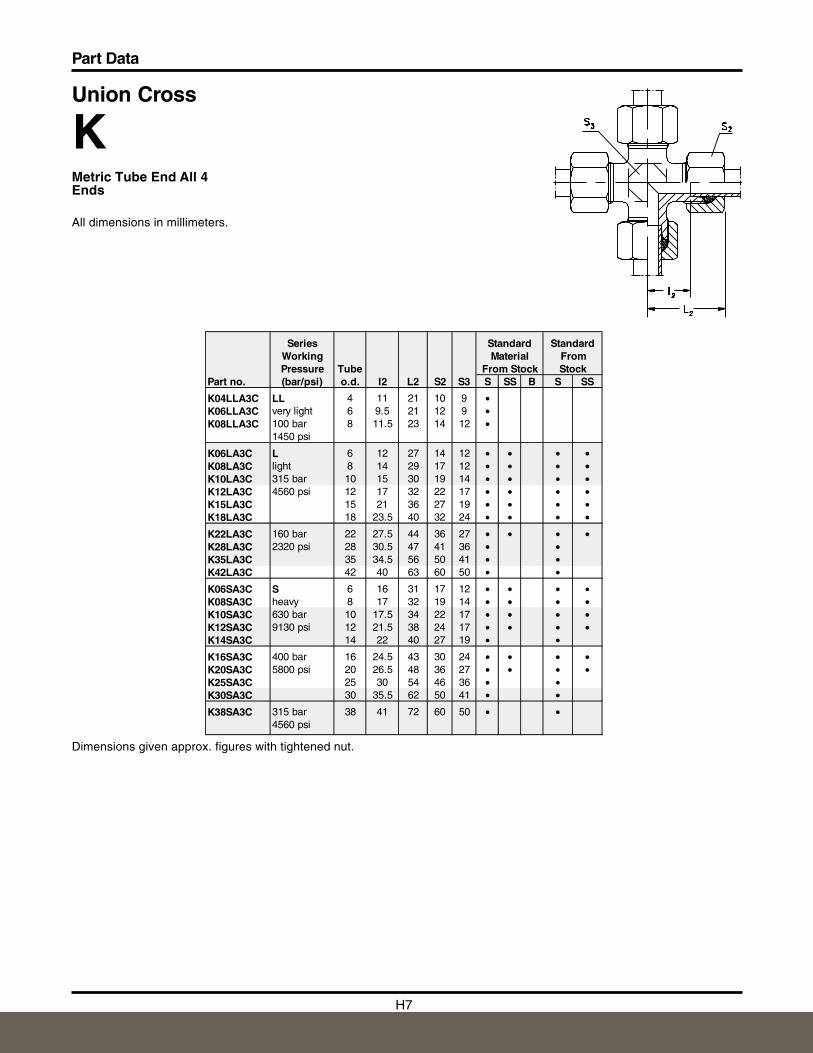
Union Cross
KMetric Tube End All 4 Ends
All dimensions in millimeters.
Dimensions given approx. figures with tightened nut.
Series Standard StandardWorking Material FromPressure Tube From Stock Stock
Part no. (bar/psi) o.d. I2 L2 S2 S3 S SS B S SS
K04LLA3C LL 4 11 21 10 9 •K06LLA3C very light 6 9.5 21 12 9 •K08LLA3C 100 bar 8 11.5 23 14 12 •
1450 psi
K06LA3C L 6 12 27 14 12 • • • •K08LA3C light 8 14 29 17 12 • • • •K10LA3C 315 bar 10 15 30 19 14 • • • •K12LA3C 4560 psi 12 17 32 22 17 • • • •K15LA3C 15 21 36 27 19 • • • •K18LA3C 18 23.5 40 32 24 • • • •
K22LA3C 160 bar 22 27.5 44 36 27 • • • •K28LA3C 2320 psi 28 30.5 47 41 36 • •K35LA3C 35 34.5 56 50 41 • •K42LA3C 42 40 63 60 50 • •
K06SA3C S 6 16 31 17 12 • • • •K08SA3C heavy 8 17 32 19 14 • • • •K10SA3C 630 bar 10 17.5 34 22 17 • • • •K12SA3C 9130 psi 12 21.5 38 24 17 • • • •K14SA3C 14 22 40 27 19 • •
K16SA3C 400 bar 16 24.5 43 30 24 • • • •K20SA3C 5800 psi 20 26.5 48 36 27 • • • •K25SA3C 25 30 54 46 36 • •K30SA3C 30 35.5 62 50 41 • •
K38SA3C 315 bar 38 41 72 60 50 • •4560 psi
H8
Part Data
H
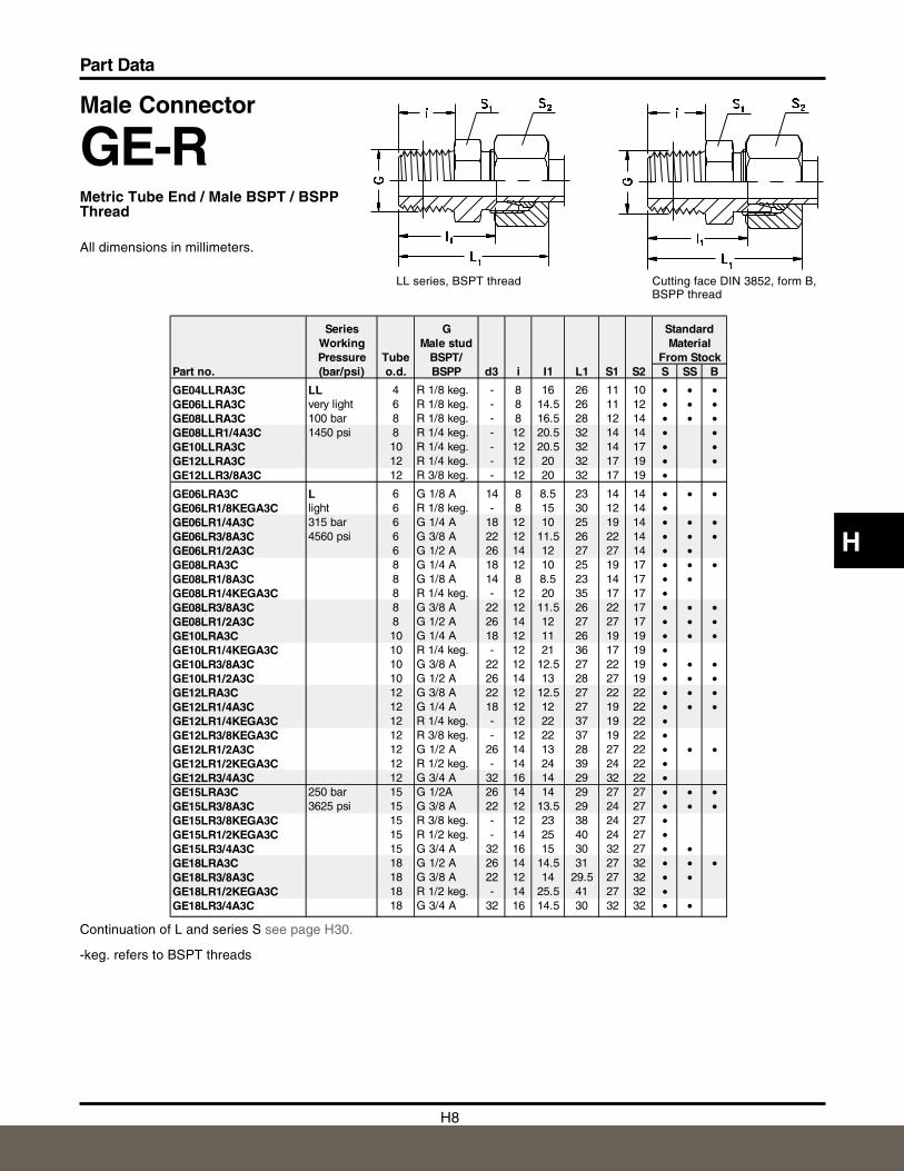
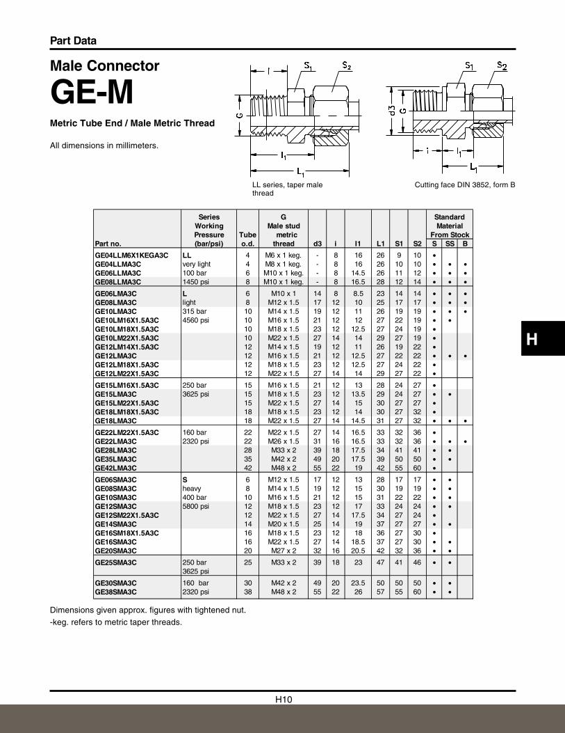
Male Connector
GE-RMetric Tube End / Male BSPT / BSPPThread
All dimensions in millimeters.
Cutting face DIN 3852, form B,BSPP thread
LL series, BSPT thread
Continuation of L and series S see page H30.
-keg. refers to BSPT threads
Series G StandardWorking Male stud MaterialPressure Tube BSPT/ From Stock
Part no. (bar/psi) o.d. BSPP d3 i I1 L1 S1 S2 S SS B
GE04LLRA3C LL 4 R 1/8 keg. - 8 16 26 11 10 • • •GE06LLRA3C very light 6 R 1/8 keg. - 8 14.5 26 11 12 • • •GE08LLRA3C 100 bar 8 R 1/8 keg. - 8 16.5 28 12 14 • • •GE08LLR1/4A3C 1450 psi 8 R 1/4 keg. - 12 20.5 32 14 14 • •GE10LLRA3C 10 R 1/4 keg. - 12 20.5 32 14 17 • •GE12LLRA3C 12 R 1/4 keg. - 12 20 32 17 19 • •GE12LLR3/8A3C 12 R 3/8 keg. - 12 20 32 17 19 •
GE06LRA3C L 6 G 1/8 A 14 8 8.5 23 14 14 • • •GE06LR1/8KEGA3C light 6 R 1/8 keg. - 8 15 30 12 14 •GE06LR1/4A3C 315 bar 6 G 1/4 A 18 12 10 25 19 14 • • •GE06LR3/8A3C 4560 psi 6 G 3/8 A 22 12 11.5 26 22 14 • • •GE06LR1/2A3C 6 G 1/2 A 26 14 12 27 27 14 • •GE08LRA3C 8 G 1/4 A 18 12 10 25 19 17 • • •GE08LR1/8A3C 8 G 1/8 A 14 8 8.5 23 14 17 • •GE08LR1/4KEGA3C 8 R 1/4 keg. - 12 20 35 17 17 •GE08LR3/8A3C 8 G 3/8 A 22 12 11.5 26 22 17 • • •GE08LR1/2A3C 8 G 1/2 A 26 14 12 27 27 17 • • •GE10LRA3C 10 G 1/4 A 18 12 11 26 19 19 • • •GE10LR1/4KEGA3C 10 R 1/4 keg. - 12 21 36 17 19 •GE10LR3/8A3C 10 G 3/8 A 22 12 12.5 27 22 19 • • •GE10LR1/2A3C 10 G 1/2 A 26 14 13 28 27 19 • • •GE12LRA3C 12 G 3/8 A 22 12 12.5 27 22 22 • • •GE12LR1/4A3C 12 G 1/4 A 18 12 12 27 19 22 • • •GE12LR1/4KEGA3C 12 R 1/4 keg. - 12 22 37 19 22 •GE12LR3/8KEGA3C 12 R 3/8 keg. - 12 22 37 19 22 •GE12LR1/2A3C 12 G 1/2 A 26 14 13 28 27 22 • • •GE12LR1/2KEGA3C 12 R 1/2 keg. - 14 24 39 24 22 •GE12LR3/4A3C 12 G 3/4 A 32 16 14 29 32 22 •GE15LRA3C 250 bar 15 G 1/2A 26 14 14 29 27 27 • • •GE15LR3/8A3C 3625 psi 15 G 3/8 A 22 12 13.5 29 24 27 • • •GE15LR3/8KEGA3C 15 R 3/8 keg. - 12 23 38 24 27 •GE15LR1/2KEGA3C 15 R 1/2 keg. - 14 25 40 24 27 •GE15LR3/4A3C 15 G 3/4 A 32 16 15 30 32 27 • •GE18LRA3C 18 G 1/2 A 26 14 14.5 31 27 32 • • •GE18LR3/8A3C 18 G 3/8 A 22 12 14 29.5 27 32 • •GE18LR1/2KEGA3C 18 R 1/2 keg. - 14 25.5 41 27 32 •GE18LR3/4A3C 18 G 3/4 A 32 16 14.5 30 32 32 • •
H9
Part Data
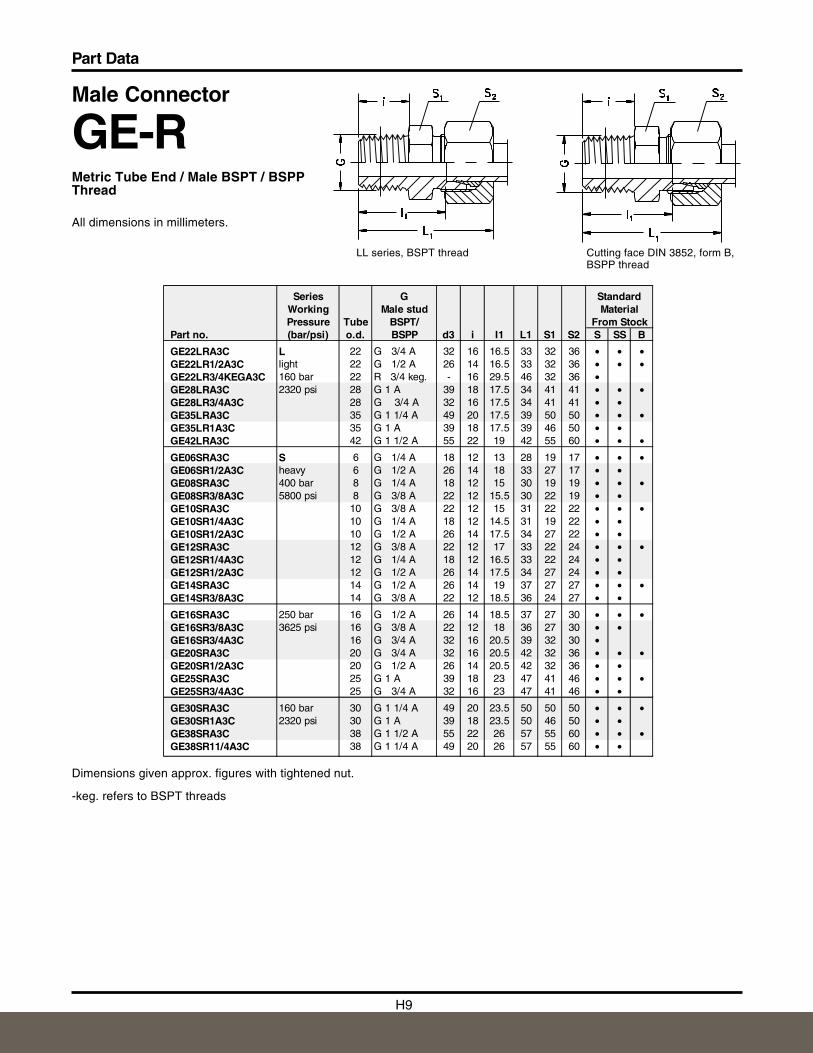
Male Connector
GE-RMetric Tube End / Male BSPT / BSPPThread
All dimensions in millimeters.
Dimensions given approx. figures with tightened nut.
-keg. refers to BSPT threads
Cutting face DIN 3852, form B,BSPP thread
LL series, BSPT thread
Series G StandardWorking Male stud MaterialPressure Tube BSPT/ From Stock
Part no. (bar/psi) o.d. BSPP d3 i I1 L1 S1 S2 S SS B
GE22LRA3C L 22 G 3/4 A 32 16 16.5 33 32 36 • • •GE22LR1/2A3C light 22 G 1/2 A 26 14 16.5 33 32 36 • • •GE22LR3/4KEGA3C 160 bar 22 R 3/4 keg. - 16 29.5 46 32 36 •GE28LRA3C 2320 psi 28 G 1 A 39 18 17.5 34 41 41 • • •GE28LR3/4A3C 28 G 3/4 A 32 16 17.5 34 41 41 • •GE35LRA3C 35 G 1 1/4 A 49 20 17.5 39 50 50 • • •GE35LR1A3C 35 G 1 A 39 18 17.5 39 46 50 • •GE42LRA3C 42 G 1 1/2 A 55 22 19 42 55 60 • • •
GE06SRA3C S 6 G 1/4 A 18 12 13 28 19 17 • • •GE06SR1/2A3C heavy 6 G 1/2 A 26 14 18 33 27 17 • •GE08SRA3C 400 bar 8 G 1/4 A 18 12 15 30 19 19 • • •GE08SR3/8A3C 5800 psi 8 G 3/8 A 22 12 15.5 30 22 19 • •GE10SRA3C 10 G 3/8 A 22 12 15 31 22 22 • • •GE10SR1/4A3C 10 G 1/4 A 18 12 14.5 31 19 22 • •GE10SR1/2A3C 10 G 1/2 A 26 14 17.5 34 27 22 • •GE12SRA3C 12 G 3/8 A 22 12 17 33 22 24 • • •GE12SR1/4A3C 12 G 1/4 A 18 12 16.5 33 22 24 • •GE12SR1/2A3C 12 G 1/2 A 26 14 17.5 34 27 24 • •GE14SRA3C 14 G 1/2 A 26 14 19 37 27 27 • • •GE14SR3/8A3C 14 G 3/8 A 22 12 18.5 36 24 27 • •
GE16SRA3C 250 bar 16 G 1/2 A 26 14 18.5 37 27 30 • • •GE16SR3/8A3C 3625 psi 16 G 3/8 A 22 12 18 36 27 30 • •GE16SR3/4A3C 16 G 3/4 A 32 16 20.5 39 32 30 •GE20SRA3C 20 G 3/4 A 32 16 20.5 42 32 36 • • •GE20SR1/2A3C 20 G 1/2 A 26 14 20.5 42 32 36 • •GE25SRA3C 25 G 1 A 39 18 23 47 41 46 • • •GE25SR3/4A3C 25 G 3/4 A 32 16 23 47 41 46 • •
GE30SRA3C 160 bar 30 G 1 1/4 A 49 20 23.5 50 50 50 • • •GE30SR1A3C 2320 psi 30 G 1 A 39 18 23.5 50 46 50 • •GE38SRA3C 38 G 1 1/2 A 55 22 26 57 55 60 • • •GE38SR11/4A3C 38 G 1 1/4 A 49 20 26 57 55 60 • •
H10
Part Data
H
Cutting face DIN 3852, form BLL series, taper malethread
Male Connector
GE-MMetric Tube End / Male Metric Thread
All dimensions in millimeters.
Dimensions given approx. figures with tightened nut.
-keg. refers to metric taper threads.
Series G StandardWorking Male stud MaterialPressure Tube metric From Stock
Part no. (bar/psi) o.d. thread d3 i I1 L1 S1 S2 S SS B
GE04LLM6X1KEGA3C LL 4 M6 x 1 keg. - 8 16 26 9 10 •GE04LLMA3C very light 4 M8 x 1 keg. - 8 16 26 10 10 • • •GE06LLMA3C 100 bar 6 M10 x 1 keg. - 8 14.5 26 11 12 • • •GE08LLMA3C 1450 psi 8 M10 x 1 keg. - 8 16.5 28 12 14 • • •
GE06LMA3C L 6 M10 x 1 14 8 8.5 23 14 14 • • •GE08LMA3C light 8 M12 x 1.5 17 12 10 25 17 17 • • •GE10LMA3C 315 bar 10 M14 x 1.5 19 12 11 26 19 19 • • •GE10LM16X1.5A3C 4560 psi 10 M16 x 1.5 21 12 12 27 22 19 • •GE10LM18X1.5A3C 10 M18 x 1.5 23 12 12.5 27 24 19 •GE10LM22X1.5A3C 10 M22 x 1.5 27 14 14 29 27 19 •GE12LM14X1.5A3C 12 M14 x 1.5 19 12 11 26 19 22 •GE12LMA3C 12 M16 x 1.5 21 12 12.5 27 22 22 • • •GE12LM18X1.5A3C 12 M18 x 1.5 23 12 12.5 27 24 22 •GE12LM22X1.5A3C 12 M22 x 1.5 27 14 14 29 27 22 •
GE15LM16X1.5A3C 250 bar 15 M16 x 1.5 21 12 13 28 24 27 •GE15LMA3C 3625 psi 15 M18 x 1.5 23 12 13.5 29 24 27 • •GE15LM22X1.5A3C 15 M22 x 1.5 27 14 15 30 27 27 •GE18LM18X1.5A3C 18 M18 x 1.5 23 12 14 30 27 32 •GE18LMA3C 18 M22 x 1.5 27 14 14.5 31 27 32 • • •
GE22LM22X1.5A3C 160 bar 22 M22 x 1.5 27 14 16.5 33 32 36 •GE22LMA3C 2320 psi 22 M26 x 1.5 31 16 16.5 33 32 36 • • •GE28LMA3C 28 M33 x 2 39 18 17.5 34 41 41 • •GE35LMA3C 35 M42 x 2 49 20 17.5 39 50 50 • •GE42LMA3C 42 M48 x 2 55 22 19 42 55 60 •
GE06SMA3C S 6 M12 x 1.5 17 12 13 28 17 17 • •GE08SMA3C heavy 8 M14 x 1.5 19 12 15 30 19 19 • •GE10SMA3C 400 bar 10 M16 x 1.5 21 12 15 31 22 22 • •GE12SMA3C 5800 psi 12 M18 x 1.5 23 12 17 33 24 24 • •GE12SM22X1.5A3C 12 M22 x 1.5 27 14 17.5 34 27 24 •GE14SMA3C 14 M20 x 1.5 25 14 19 37 27 27 • •GE16SM18X1.5A3C 16 M18 x 1.5 23 12 18 36 27 30 •GE16SMA3C 16 M22 x 1.5 27 14 18.5 37 27 30 • •GE20SMA3C 20 M27 x 2 32 16 20.5 42 32 36 • •
GE25SMA3C 250 bar 25 M33 x 2 39 18 23 47 41 46 • •3625 psi
GE30SMA3C 160 bar 30 M42 x 2 49 20 23.5 50 50 50 • •GE38SMA3C 2320 psi 38 M48 x 2 55 22 26 57 55 60 • •
H11
Part Data
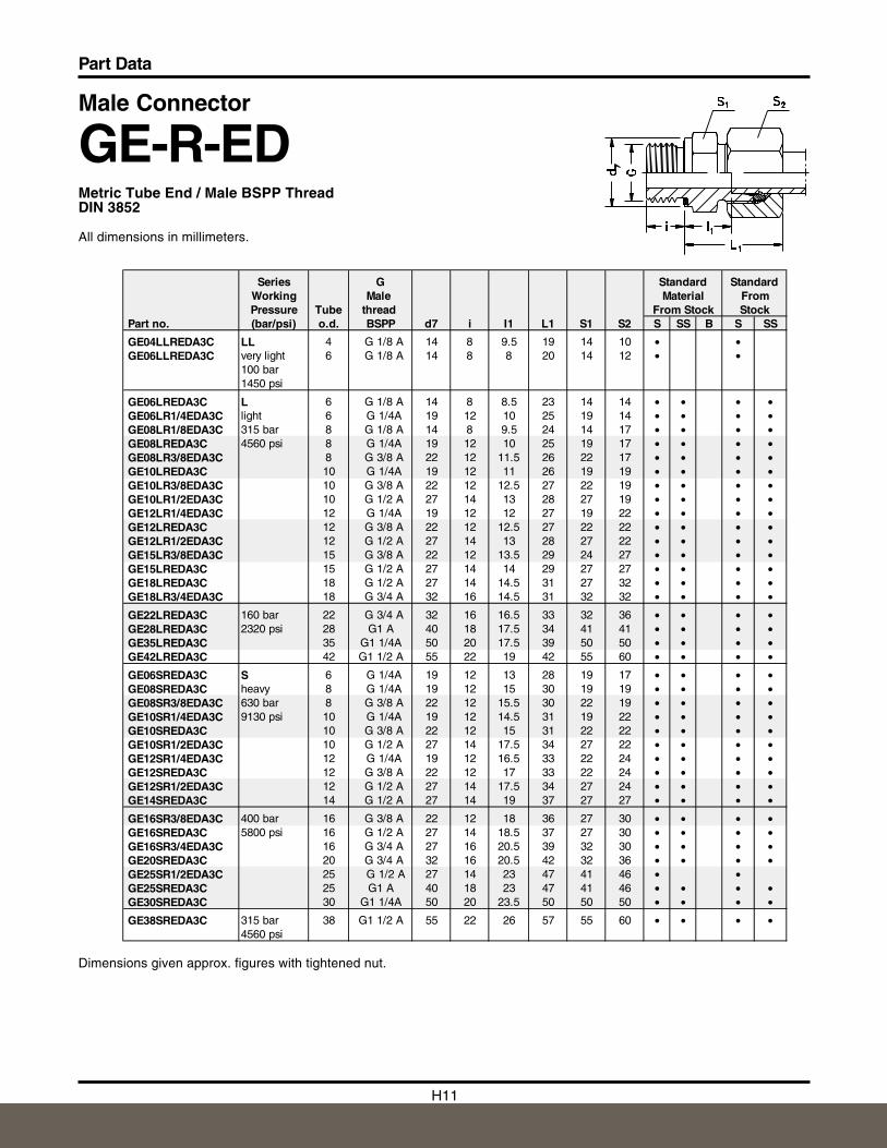
Male Connector
GE-R-EDMetric Tube End / Male BSPP ThreadDIN 3852
All dimensions in millimeters.
Dimensions given approx. figures with tightened nut.
Series G Standard StandardWorking Male Material FromPressure Tube thread From Stock Stock
Part no. (bar/psi) o.d. BSPP d7 i I1 L1 S1 S2 S SS B S SS
GE04LLREDA3C LL 4 G 1/8 A 14 8 9.5 19 14 10 • •GE06LLREDA3C very light 6 G 1/8 A 14 8 8 20 14 12 • •
100 bar1450 psi
GE06LREDA3C L 6 G 1/8 A 14 8 8.5 23 14 14 • • • •GE06LR1/4EDA3C light 6 G 1/4A 19 12 10 25 19 14 • • • •GE08LR1/8EDA3C 315 bar 8 G 1/8 A 14 8 9.5 24 14 17 • • • •GE08LREDA3C 4560 psi 8 G 1/4A 19 12 10 25 19 17 • • • •GE08LR3/8EDA3C 8 G 3/8 A 22 12 11.5 26 22 17 • • • •GE10LREDA3C 10 G 1/4A 19 12 11 26 19 19 • • • •GE10LR3/8EDA3C 10 G 3/8 A 22 12 12.5 27 22 19 • • • •GE10LR1/2EDA3C 10 G 1/2 A 27 14 13 28 27 19 • • • •GE12LR1/4EDA3C 12 G 1/4A 19 12 12 27 19 22 • • • •GE12LREDA3C 12 G 3/8 A 22 12 12.5 27 22 22 • • • •GE12LR1/2EDA3C 12 G 1/2 A 27 14 13 28 27 22 • • • •GE15LR3/8EDA3C 15 G 3/8 A 22 12 13.5 29 24 27 • • • •GE15LREDA3C 15 G 1/2 A 27 14 14 29 27 27 • • • •GE18LREDA3C 18 G 1/2 A 27 14 14.5 31 27 32 • • • •GE18LR3/4EDA3C 18 G 3/4 A 32 16 14.5 31 32 32 • • • •
GE22LREDA3C 160 bar 22 G 3/4 A 32 16 16.5 33 32 36 • • • •GE28LREDA3C 2320 psi 28 G1 A 40 18 17.5 34 41 41 • • • •GE35LREDA3C 35 G1 1/4A 50 20 17.5 39 50 50 • • • •GE42LREDA3C 42 G1 1/2 A 55 22 19 42 55 60 • • • •
GE06SREDA3C S 6 G 1/4A 19 12 13 28 19 17 • • • •GE08SREDA3C heavy 8 G 1/4A 19 12 15 30 19 19 • • • •GE08SR3/8EDA3C 630 bar 8 G 3/8 A 22 12 15.5 30 22 19 • • • •GE10SR1/4EDA3C 9130 psi 10 G 1/4A 19 12 14.5 31 19 22 • • • •GE10SREDA3C 10 G 3/8 A 22 12 15 31 22 22 • • • •GE10SR1/2EDA3C 10 G 1/2 A 27 14 17.5 34 27 22 • • • •GE12SR1/4EDA3C 12 G 1/4A 19 12 16.5 33 22 24 • • • •GE12SREDA3C 12 G 3/8 A 22 12 17 33 22 24 • • • •GE12SR1/2EDA3C 12 G 1/2 A 27 14 17.5 34 27 24 • • • •GE14SREDA3C 14 G 1/2 A 27 14 19 37 27 27 • • • •
GE16SR3/8EDA3C 400 bar 16 G 3/8 A 22 12 18 36 27 30 • • • •GE16SREDA3C 5800 psi 16 G 1/2 A 27 14 18.5 37 27 30 • • • •GE16SR3/4EDA3C 16 G 3/4 A 27 16 20.5 39 32 30 • • • •GE20SREDA3C 20 G 3/4 A 32 16 20.5 42 32 36 • • • •GE25SR1/2EDA3C 25 G 1/2 A 27 14 23 47 41 46 • •GE25SREDA3C 25 G1 A 40 18 23 47 41 46 • • • •GE30SREDA3C 30 G1 1/4A 50 20 23.5 50 50 50 • • • •
GE38SREDA3C 315 bar 38 G1 1/2 A 55 22 26 57 55 60 • • • •4560 psi
H12
Part Data
H
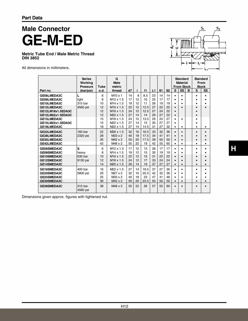
Male Connector
GE-M-EDMetric Tube End / Male Metric ThreadDIN 3852
All dimensions in millimeters.
Dimensions given approx. figures with tightened nut.
Series G Standard StandardWorking Male Material FromPressure Tube metric From Stock Stock
Part no. (bar/psi) o.d. thread d7 i I1 L1 S1 S2 S SS B S SS
GE06LMEDA3C L 6 M10 x 1 14 8 8.5 23 14 14 • • • •GE08LMEDA3C light 8 M12 x 1.5 17 12 10 25 17 17 • • • •GE10LMEDA3C 315 bar 10 M14 x 1.5 19 12 11 26 19 19 • • • •GE12LMEDA3C 4560 psi 12 M16 x 1.5 22 12 12.5 27 22 22 • • • •GE12LM18x1.5EDA3C 12 M18 x 1.5 24 12 12.5 27 24 22 • •GE12LM22x1.5EDA3C 12 M22 x 1.5 27 14 14 29 27 22 • •GE15LMEDA3C 15 M18 x 1.5 24 12 13.5 29 24 27 • • •GE15LM22x1.5EDA3C 15 M22 x 1.5 27 14 15 30 27 27 • •GE18LMEDA3C 18 M22 x 1.5 27 14 14.5 31 27 32 • • • •
GE22LMEDA3C 160 bar 22 M26 x 1.5 32 16 16.5 33 32 36 • • • •GE28LMEDA3C 2320 psi 28 M33 x 2 40 18 17.5 34 41 41 • • • •GE35LMEDA3C 35 M42 x 2 50 20 17.5 39 50 50 • • • •GE42LMEDA3C 42 M48 x 2 55 22 19 42 55 60 • • • •
GE06SMEDA3C S 6 M12 x 1.5 17 12 13 28 17 17 • • • •GE08SMEDA3C heavy 8 M14 x 1.5 19 12 15 30 19 19 • • • •GE10SMEDA3C 630 bar 10 M16 x 1.5 22 12 15 31 22 22 • • • •GE12SMEDA3C 9130 psi 12 M18 x 1.5 24 12 17 33 24 24 • • • •GE14SMEDA3C 14 M20 x 1.5 26 14 19 37 27 27 • • • •
GE16SMEDA3C 400 bar 16 M22 x 1.5 27 14 18.5 37 27 30 • • • •GE20SMEDA3C 5800 psi 20 M27 x 2 32 16 20.5 42 32 36 • • • •GE25SMEDA3C 25 M33 x 2 40 18 23 47 41 46 • • • •GE30SMEDA3C 30 M42 x 2 50 20 23.5 50 50 50 • • • •
GE38SMEDA3C 315 bar 38 M48 x 2 55 22 26 57 55 60 • • • •4560 psi
H13
Part Data
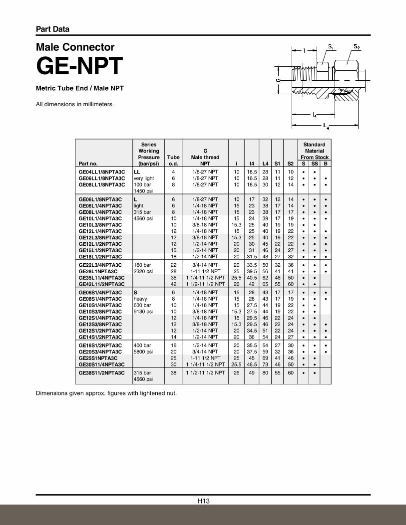
Male Connector
GE-NPTMetric Tube End / Male NPT
All dimensions in millimeters.
Dimensions given approx. figures with tightened nut.
Series StandardWorking G MaterialPressure Tube Male thread From Stock
Part no. (bar/psi) o.d. NPT i I4 L4 S1 S2 S SS B
GE04LL1/8NPTA3C LL 4 1/8-27 NPT 10 18.5 28 11 10 • •GE06LL1/8NPTA3C very light 6 1/8-27 NPT 10 16.5 28 11 12 • • •GE08LL1/8NPTA3C 100 bar 8 1/8-27 NPT 10 18.5 30 12 14 • • •
1450 psi
GE06L1/8NPTA3C L 6 1/8-27 NPT 10 17 32 12 14 • • •GE06L1/4NPTA3C light 6 1/4-18 NPT 15 23 38 17 14 • • •GE08L1/4NPTA3C 315 bar 8 1/4-18 NPT 15 23 38 17 17 • • •GE10L1/4NPTA3C 4560 psi 10 1/4-18 NPT 15 24 39 17 19 • • •GE10L3/8NPTA3C 10 3/8-18 NPT 15.3 25 40 19 19 • •GE12L1/4NPTA3C 12 1/4-18 NPT 15 25 40 19 22 • • •GE12L3/8NPTA3C 12 3/8-18 NPT 15.3 25 40 19 22 • • •GE12L1/2NPTA3C 12 1/2-14 NPT 20 30 45 22 22 • • •GE15L1/2NPTA3C 15 1/2-14 NPT 20 31 46 24 27 • • •GE18L1/2NPTA3C 18 1/2-14 NPT 20 31.5 48 27 32 • • •
GE22L3/4NPTA3C 160 bar 22 3/4-14 NPT 20 33.5 50 32 36 • • •GE28L1NPTA3C 2320 psi 28 1-11 1/2 NPT 25 39.5 56 41 41 • • •GE35L11/4NPTA3C 35 1 1/4-11 1/2 NPT 25.5 40.5 62 46 50 • •GE42L11/2NPTA3C 42 1 1/2-11 1/2 NPT 26 42 65 55 60 • •
GE06S1/4NPTA3C S 6 1/4-18 NPT 15 28 43 17 17 • • •GE08S1/4NPTA3C heavy 8 1/4-18 NPT 15 28 43 17 19 • • •GE10S1/4NPTA3C 630 bar 10 1/4-18 NPT 15 27.5 44 19 22 • •GE10S3/8NPTA3C 9130 psi 10 3/8-18 NPT 15.3 27.5 44 19 22 • •GE12S1/4NPTA3C 12 1/4-18 NPT 15 29.5 46 22 24 • •GE12S3/8NPTA3C 12 3/8-18 NPT 15.3 29.5 46 22 24 • • •GE12S1/2NPTA3C 12 1/2-14 NPT 20 34.5 51 22 24 • • •GE14S1/2NPTA3C 14 1/2-14 NPT 20 36 54 24 27 • • •
GE16S1/2NPTA3C 400 bar 16 1/2-14 NPT 20 35.5 54 27 30 • • •GE20S3/4NPTA3C 5800 psi 20 3/4-14 NPT 20 37.5 59 32 36 • • •GE25S1NPTA3C 25 1-11 1/2 NPT 25 45 69 41 46 • •GE30S11/4NPTA3C 30 1 1/4-11 1/2 NPT 25.5 46.5 73 46 50 • •
GE38S11/2NPTA3C 315 bar 38 1 1/2-11 1/2 NPT 26 49 80 55 60 • •4560 psi
H14
Part Data
H
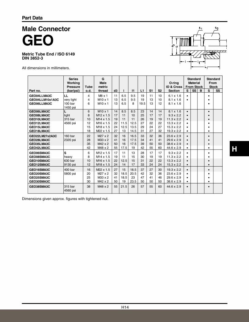
Male Connector
GEOMetric Tube End / ISO 6149DIN 3852-3
All dimensions in millimeters.
Dimensions given approx. figures with tightened nut.
Series G Standard StandardWorking Male O-ring Material FromPressure Tube metric ID & Cross From Stock Stock
Part no. (bar/psi) o.d. thread d3 i I1 L1 S1 S2 Section S SS B S SS
GEO04LLMA3C LL 4 M8 x 1 11 6.5 9.5 19 11 10 6.1 x 1.6 • •GEO04LLM10x1A3C very light 4 M10 x 1 13 6.5 9.5 19 13 10 8.1 x 1.6 • •GEO06LLMA3C 100 bar 6 M10 x 1 13 6.5 8 19.5 13 12 8.1 x 1.6 •
1450 psiGEO06LMA3C L 6 M10 x 1 14 8.5 8.5 23 14 14 8.1 x 1.6 • •GEO08LMA3C light 8 M12 x 1.5 17 11 10 25 17 17 9.3 x 2.2 • •GEO10LMA3C 315 bar 10 M14 x 1.5 19 11 11 26 19 19 11.3 x 2.2 • •GEO12LMA3C 4560 psi 12 M16 x 1.5 22 11.5 12.5 27 22 22 13.3 x 2.2 • •GEO15LMA3C 15 M18 x 1.5 24 12.5 13.5 29 24 27 15.3 x 2.2 • •GEO18LMA3C 18 M22 x 1.5 27 13 14.5 31 27 32 19.3 x 2.2 • •
GEO22LM27x2A3C 160 bar 22 M27 x 2 32 16 16.5 33 32 36 23.6 x 2.9 • •GEO28LMA3C 2320 psi 28 M33 x 2 41 16 17.5 34 41 41 29.6 x 2.9 • •GEO35LMA3C 35 M42 x 2 50 16 17.5 39 50 50 38.6 x 2.9 • •GEO42LMA3C 42 M48 x 2 55 17.5 19 42 55 60 44.6 x 2.9 • •
GEO06SMA3C S 6 M12 x 1.5 17 11 13 28 17 17 9.3 x 2.2 • •GEO08SMA3C heavy 8 M14 x 1.5 19 11 15 30 19 19 11.3 x 2.2 • •GEO10SMA3C 630 bar 10 M16 x 1.5 22 12.5 15 31 22 22 13.3 x 2.2 • •GEO12SMA3C 9130 psi 12 M18 x 1.5 24 14 17 33 24 24 15.3 x 2.2 • •
GEO16SMA3C 400 bar 16 M22 x 1.5 27 15 18.5 37 27 30 19.3 x 2.2 • •GEO20SMA3C 5800 psi 20 M27 x 2 32 18.5 20.5 42 32 36 23.6 x 2.9 • •GEO25SMA3C 25 M33 x 2 41 18.5 23 47 41 46 29.6 x 2.9 • •GEO30SMA3C 30 M42 x 2 50 19 23.5 50 50 50 38.6 x 2.9 • •
GEO38SMA3C 315 bar 38 M48 x 2 55 21.5 26 57 55 60 44.6 x 2.9 • •4560 psi
H15
Part Data
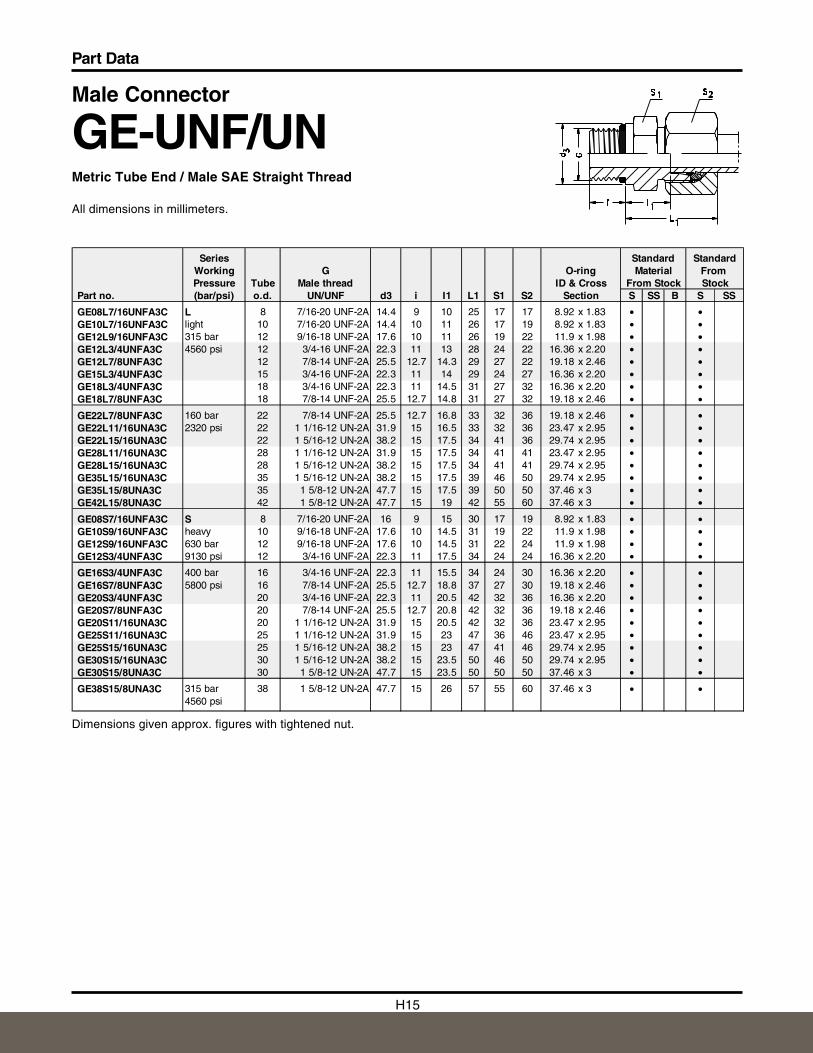
Male Connector
GE-UNF/UNMetric Tube End / Male SAE Straight Thread
All dimensions in millimeters.
Dimensions given approx. figures with tightened nut.
Series Standard StandardWorking G O-ring Material FromPressure Tube Male thread ID & Cross From Stock Stock
Part no. (bar/psi) o.d. UN/UNF d3 i I1 L1 S1 S2 Section S SS B S SS
GE08L7/16UNFA3C L 8 7/16-20 UNF-2A 14.4 9 10 25 17 17 8.92 x 1.83 • •GE10L7/16UNFA3C light 10 7/16-20 UNF-2A 14.4 10 11 26 17 19 8.92 x 1.83 • •GE12L9/16UNFA3C 315 bar 12 9/16-18 UNF-2A 17.6 10 11 26 19 22 11.9 x 1.98 • •GE12L3/4UNFA3C 4560 psi 12 3/4-16 UNF-2A 22.3 11 13 28 24 22 16.36 x 2.20 • •GE12L7/8UNFA3C 12 7/8-14 UNF-2A 25.5 12.7 14.3 29 27 22 19.18 x 2.46 • •GE15L3/4UNFA3C 15 3/4-16 UNF-2A 22.3 11 14 29 24 27 16.36 x 2.20 • •GE18L3/4UNFA3C 18 3/4-16 UNF-2A 22.3 11 14.5 31 27 32 16.36 x 2.20 • •GE18L7/8UNFA3C 18 7/8-14 UNF-2A 25.5 12.7 14.8 31 27 32 19.18 x 2.46 • •
GE22L7/8UNFA3C 160 bar 22 7/8-14 UNF-2A 25.5 12.7 16.8 33 32 36 19.18 x 2.46 • •GE22L11/16UNA3C 2320 psi 22 1 1/16-12 UN-2A 31.9 15 16.5 33 32 36 23.47 x 2.95 • •GE22L15/16UNA3C 22 1 5/16-12 UN-2A 38.2 15 17.5 34 41 36 29.74 x 2.95 • •GE28L11/16UNA3C 28 1 1/16-12 UN-2A 31.9 15 17.5 34 41 41 23.47 x 2.95 • •GE28L15/16UNA3C 28 1 5/16-12 UN-2A 38.2 15 17.5 34 41 41 29.74 x 2.95 • •GE35L15/16UNA3C 35 1 5/16-12 UN-2A 38.2 15 17.5 39 46 50 29.74 x 2.95 • •GE35L15/8UNA3C 35 1 5/8-12 UN-2A 47.7 15 17.5 39 50 50 37.46 x 3 • •GE42L15/8UNA3C 42 1 5/8-12 UN-2A 47.7 15 19 42 55 60 37.46 x 3 • •
GE08S7/16UNFA3C S 8 7/16-20 UNF-2A 16 9 15 30 17 19 8.92 x 1.83 • •GE10S9/16UNFA3C heavy 10 9/16-18 UNF-2A 17.6 10 14.5 31 19 22 11.9 x 1.98 • •GE12S9/16UNFA3C 630 bar 12 9/16-18 UNF-2A 17.6 10 14.5 31 22 24 11.9 x 1.98 • •GE12S3/4UNFA3C 9130 psi 12 3/4-16 UNF-2A 22.3 11 17.5 34 24 24 16.36 x 2.20 • •
GE16S3/4UNFA3C 400 bar 16 3/4-16 UNF-2A 22.3 11 15.5 34 24 30 16.36 x 2.20 • •GE16S7/8UNFA3C 5800 psi 16 7/8-14 UNF-2A 25.5 12.7 18.8 37 27 30 19.18 x 2.46 • •GE20S3/4UNFA3C 20 3/4-16 UNF-2A 22.3 11 20.5 42 32 36 16.36 x 2.20 • •GE20S7/8UNFA3C 20 7/8-14 UNF-2A 25.5 12.7 20.8 42 32 36 19.18 x 2.46 • •GE20S11/16UNA3C 20 1 1/16-12 UN-2A 31.9 15 20.5 42 32 36 23.47 x 2.95 • •GE25S11/16UNA3C 25 1 1/16-12 UN-2A 31.9 15 23 47 36 46 23.47 x 2.95 • •GE25S15/16UNA3C 25 1 5/16-12 UN-2A 38.2 15 23 47 41 46 29.74 x 2.95 • •GE30S15/16UNA3C 30 1 5/16-12 UN-2A 38.2 15 23.5 50 46 50 29.74 x 2.95 • •GE30S15/8UNA3C 30 1 5/8-12 UN-2A 47.7 15 23.5 50 50 50 37.46 x 3 • •
GE38S15/8UNA3C 315 bar 38 1 5/8-12 UN-2A 47.7 15 26 57 55 60 37.46 x 3 • •4560 psi
H16
Part Data
H
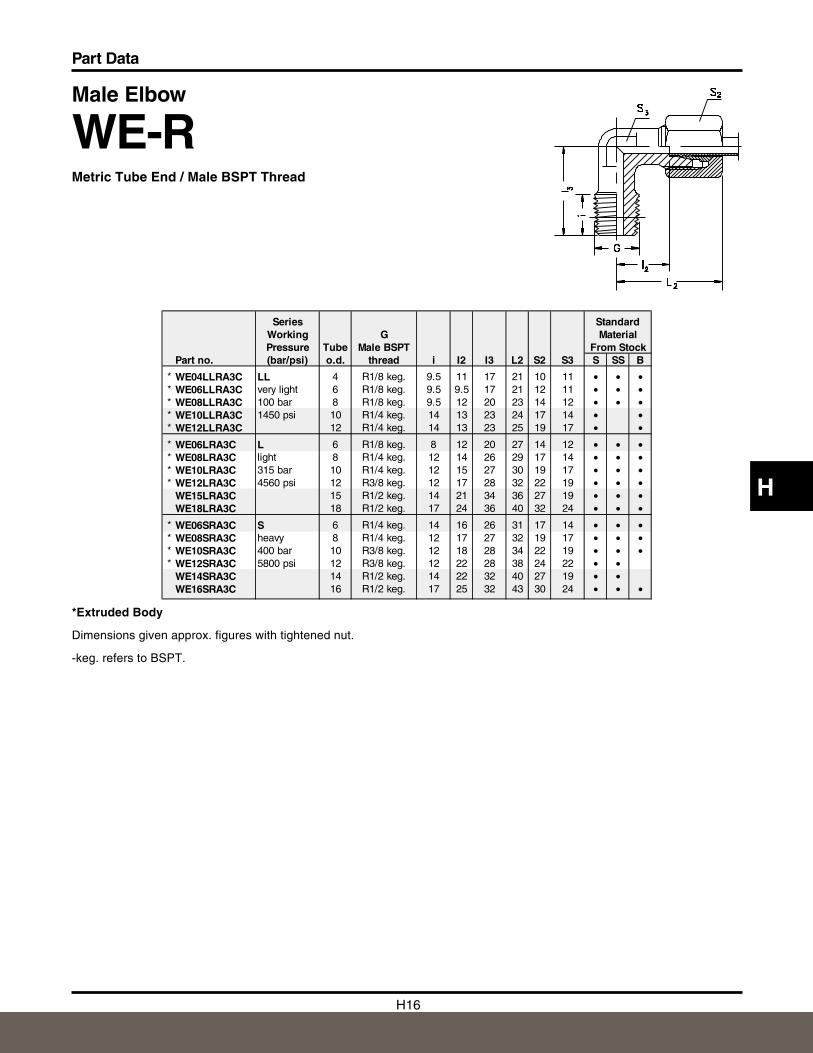
Male Elbow
WE-RMetric Tube End / Male BSPT Thread
All dimensions in millimeters.
*Extruded Body
Dimensions given approx. figures with tightened nut.
-keg. refers to BSPT.
Series StandardWorking G MaterialPressure Tube Male BSPT From Stock
Part no. (bar/psi) o.d. thread i I2 I3 L2 S2 S3 S SS B
* WE04LLRA3C LL 4 R1/8 keg. 9.5 11 17 21 10 11 • • •* WE06LLRA3C very light 6 R1/8 keg. 9.5 9.5 17 21 12 11 • • •* WE08LLRA3C 100 bar 8 R1/8 keg. 9.5 12 20 23 14 12 • • •* WE10LLRA3C 1450 psi 10 R1/4 keg. 14 13 23 24 17 14 • •* WE12LLRA3C 12 R1/4 keg. 14 13 23 25 19 17 • •* WE06LRA3C L 6 R1/8 keg. 8 12 20 27 14 12 • • •* WE08LRA3C light 8 R1/4 keg. 12 14 26 29 17 14 • • •* WE10LRA3C 315 bar 10 R1/4 keg. 12 15 27 30 19 17 • • •* WE12LRA3C 4560 psi 12 R3/8 keg. 12 17 28 32 22 19 • • •
WE15LRA3C 15 R1/2 keg. 14 21 34 36 27 19 • • •WE18LRA3C 18 R1/2 keg. 17 24 36 40 32 24 • • •
* WE06SRA3C S 6 R1/4 keg. 14 16 26 31 17 14 • • •* WE08SRA3C heavy 8 R1/4 keg. 12 17 27 32 19 17 • • •* WE10SRA3C 400 bar 10 R3/8 keg. 12 18 28 34 22 19 • • •* WE12SRA3C 5800 psi 12 R3/8 keg. 12 22 28 38 24 22 • •
WE14SRA3C 14 R1/2 keg. 14 22 32 40 27 19 • •WE16SRA3C 16 R1/2 keg. 17 25 32 43 30 24 • • •
H17
Part Data
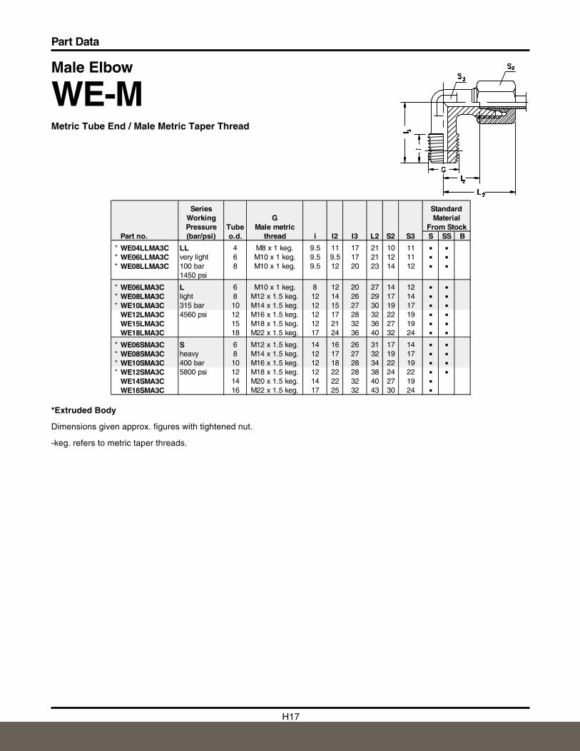
Male Elbow
WE-MMetric Tube End / Male Metric Taper Thread
All dimensions in millimeters.
*Extruded Body
Dimensions given approx. figures with tightened nut.
-keg. refers to metric taper threads.
Series StandardWorking G MaterialPressure Tube Male metric From Stock
Part no. (bar/psi) o.d. thread i I2 I3 L2 S2 S3 S SS B
* WE04LLMA3C LL 4 M8 x 1 keg. 9.5 11 17 21 10 11 • •* WE06LLMA3C very light 6 M10 x 1 keg. 9.5 9.5 17 21 12 11 • •* WE08LLMA3C 100 bar 8 M10 x 1 keg. 9.5 12 20 23 14 12 • •
1450 psi
* WE06LMA3C L 6 M10 x 1 keg. 8 12 20 27 14 12 • •* WE08LMA3C light 8 M12 x 1.5 keg. 12 14 26 29 17 14 • •* WE10LMA3C 315 bar 10 M14 x 1.5 keg. 12 15 27 30 19 17 • •
WE12LMA3C 4560 psi 12 M16 x 1.5 keg. 12 17 28 32 22 19 • •WE15LMA3C 15 M18 x 1.5 keg. 12 21 32 36 27 19 • •WE18LMA3C 18 M22 x 1.5 keg. 17 24 36 40 32 24 • •
* WE06SMA3C S 6 M12 x 1.5 keg. 14 16 26 31 17 14 • •* WE08SMA3C heavy 8 M14 x 1.5 keg. 12 17 27 32 19 17 • •* WE10SMA3C 400 bar 10 M16 x 1.5 keg. 12 18 28 34 22 19 • •* WE12SMA3C 5800 psi 12 M18 x 1.5 keg. 12 22 28 38 24 22 • •
WE14SMA3C 14 M20 x 1.5 keg. 14 22 32 40 27 19 •WE16SMA3C 16 M22 x 1.5 keg. 17 25 32 43 30 24 •
H18
Part Data
H
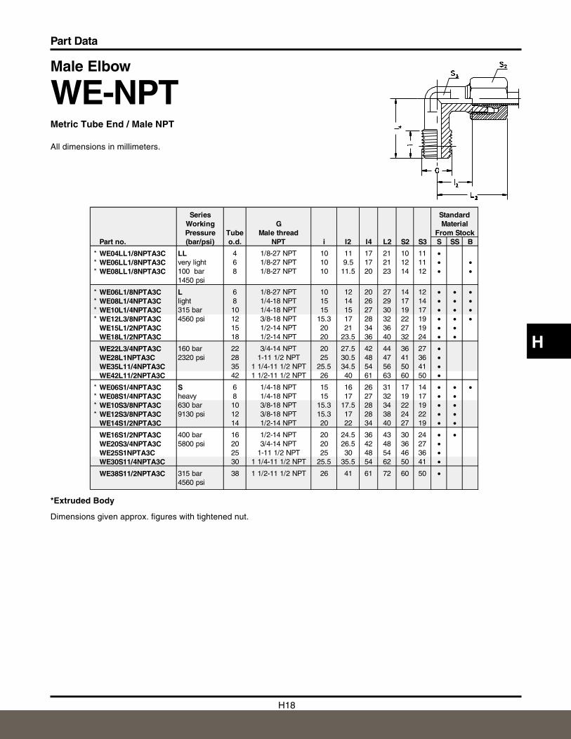
Male Elbow
WE-NPTMetric Tube End / Male NPT
All dimensions in millimeters.
*Extruded Body
Dimensions given approx. figures with tightened nut.
Series StandardWorking G MaterialPressure Tube Male thread From Stock
Part no. (bar/psi) o.d. NPT i I2 I4 L2 S2 S3 S SS B
* WE04LL1/8NPTA3C LL 4 1/8-27 NPT 10 11 17 21 10 11 •* WE06LL1/8NPTA3C very light 6 1/8-27 NPT 10 9.5 17 21 12 11 • •* WE08LL1/8NPTA3C 100 bar 8 1/8-27 NPT 10 11.5 20 23 14 12 • •
1450 psi
* WE06L1/8NPTA3C L 6 1/8-27 NPT 10 12 20 27 14 12 • • •* WE08L1/4NPTA3C light 8 1/4-18 NPT 15 14 26 29 17 14 • • •* WE10L1/4NPTA3C 315 bar 10 1/4-18 NPT 15 15 27 30 19 17 • • •* WE12L3/8NPTA3C 4560 psi 12 3/8-18 NPT 15.3 17 28 32 22 19 • • •
WE15L1/2NPTA3C 15 1/2-14 NPT 20 21 34 36 27 19 • •WE18L1/2NPTA3C 18 1/2-14 NPT 20 23.5 36 40 32 24 • •
WE22L3/4NPTA3C 160 bar 22 3/4-14 NPT 20 27.5 42 44 36 27 •WE28L1NPTA3C 2320 psi 28 1-11 1/2 NPT 25 30.5 48 47 41 36 •WE35L11/4NPTA3C 35 1 1/4-11 1/2 NPT 25.5 34.5 54 56 50 41 •WE42L11/2NPTA3C 42 1 1/2-11 1/2 NPT 26 40 61 63 60 50 •
* WE06S1/4NPTA3C S 6 1/4-18 NPT 15 16 26 31 17 14 • • •* WE08S1/4NPTA3C heavy 8 1/4-18 NPT 15 17 27 32 19 17 • •* WE10S3/8NPTA3C 630 bar 10 3/8-18 NPT 15.3 17.5 28 34 22 19 • •* WE12S3/8NPTA3C 9130 psi 12 3/8-18 NPT 15.3 17 28 38 24 22 • •
WE14S1/2NPTA3C 14 1/2-14 NPT 20 22 34 40 27 19 • •
WE16S1/2NPTA3C 400 bar 16 1/2-14 NPT 20 24.5 36 43 30 24 • •WE20S3/4NPTA3C 5800 psi 20 3/4-14 NPT 20 26.5 42 48 36 27 •WE25S1NPTA3C 25 1-11 1/2 NPT 25 30 48 54 46 36 •WE30S11/4NPTA3C 30 1 1/4-11 1/2 NPT 25.5 35.5 54 62 50 41 •
WE38S11/2NPTA3C 315 bar 38 1 1/2-11 1/2 NPT 26 41 61 72 60 50 •4560 psi
H19
Part Data
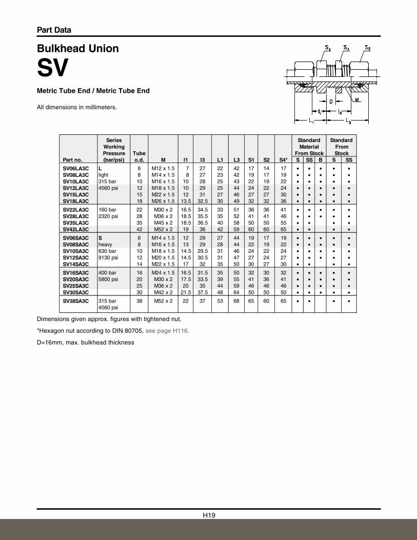
Bulkhead Union
SVMetric Tube End / Metric Tube End
All dimensions in millimeters.
Dimensions given approx. figures with tightened nut.
*Hexagon nut according to DIN 80705, see page H116.
D=16mm, max. bulkhead thickness
Series Standard StandardWorking Material FromPressure Tube From Stock Stock
Part no. (bar/psi) o.d. M I1 I3 L1 L3 S1 S2 S4* S SS B S SS
SV06LA3C L 6 M12 x 1.5 7 27 22 42 17 14 17 • • • • •SV08LA3C light 8 M14 x 1.5 8 27 23 42 19 17 19 • • • • •SV10LA3C 315 bar 10 M16 x 1.5 10 28 25 43 22 19 22 • • • • •SV12LA3C 4560 psi 12 M18 x 1.5 10 29 25 44 24 22 24 • • • • •SV15LA3C 15 M22 x 1.5 12 31 27 46 27 27 30 • • • • •SV18LA3C 18 M26 x 1.5 13.5 32.5 30 49 32 32 36 • • • • •
SV22LA3C 160 bar 22 M30 x 2 16.5 34.5 33 51 36 36 41 • • • • •SV28LA3C 2320 psi 28 M36 x 2 18.5 35.5 35 52 41 41 46 • • • • •SV35LA3C 35 M45 x 2 18.5 36.5 40 58 50 50 55 • • • •SV42LA3C 42 M52 x 2 19 36 42 59 60 60 65 • • • •
SV06SA3C S 6 M14 x 1.5 12 29 27 44 19 17 19 • • • • •SV08SA3C heavy 8 M16 x 1.5 13 29 28 44 22 19 22 • • • • •SV10SA3C 630 bar 10 M18 x 1.5 14.5 29.5 31 46 24 22 24 • • • • •SV12SA3C 9130 psi 12 M20 x 1.5 14.5 30.5 31 47 27 24 27 • • • • •SV14SA3C 14 M22 x 1.5 17 32 35 50 30 27 30 • • • •
SV16SA3C 400 bar 16 M24 x 1.5 16.5 31.5 35 50 32 30 32 • • • • •SV20SA3C 5800 psi 20 M30 x 2 17.5 33.5 39 55 41 36 41 • • • • •SV25SA3C 25 M36 x 2 20 35 44 59 46 46 46 • • • • •SV30SA3C 30 M42 x 2 21.5 37.5 48 64 50 50 50 • • • • •
SV38SA3C 315 bar 38 M52 x 2 22 37 53 68 65 60 65 • • • •4560 psi
H20
Part Data
H
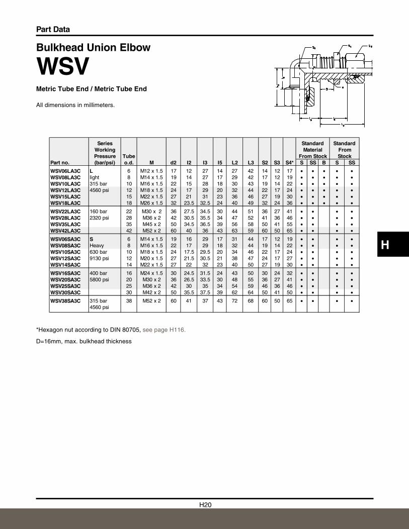
Bulkhead Union Elbow
WSVMetric Tube End / Metric Tube End
All dimensions in millimeters.
*Hexagon nut according to DIN 80705, see page H116.
D=16mm, max. bulkhead thickness
Series Standard StandardWorking Material FromPressure Tube From Stock Stock
Part no. (bar/psi) o.d. M d2 I2 I3 I5 L2 L3 S2 S3 S4* S SS B S SS
WSV06LA3C L 6 M12 x 1.5 17 12 27 14 27 42 14 12 17 • • • • •WSV08LA3C light 8 M14 x 1.5 19 14 27 17 29 42 17 12 19 • • • • •WSV10LA3C 315 bar 10 M16 x 1.5 22 15 28 18 30 43 19 14 22 • • • • •WSV12LA3C 4560 psi 12 M18 x 1.5 24 17 29 20 32 44 22 17 24 • • • • •WSV15LA3C 15 M22 x 1.5 27 21 31 23 36 46 27 19 30 • • • • •WSV18LA3C 18 M26 x 1.5 32 23.5 32.5 24 40 49 32 24 36 • • • • •
WSV22LA3C 160 bar 22 M30 x 2 36 27.5 34.5 30 44 51 36 27 41 • • • •WSV28LA3C 2320 psi 28 M36 x 2 42 30.5 35.5 34 47 52 41 36 46 • • • •WSV35LA3C 35 M45 x 2 50 34.5 36.5 39 56 58 50 41 55 • • • •WSV42LA3C 42 M52 x 2 60 40 36 43 63 59 60 50 65 • • • •
WSV06SA3C S 6 M14 x 1.5 19 16 29 17 31 44 17 12 19 • • • •WSV08SA3C Heavy 8 M16 x 1.5 22 17 29 18 32 44 19 14 22 • • • •WSV10SA3C 630 bar 10 M18 x 1.5 24 17.5 29.5 20 34 46 22 17 24 • • • •WSV12SA3C 9130 psi 12 M20 x 1.5 27 21.5 30.5 21 38 47 24 17 27 • • • •WSV14SA3C 14 M22 x 1.5 27 22 32 23 40 50 27 19 30 • • • •
WSV16SA3C 400 bar 16 M24 x 1.5 30 24.5 31.5 24 43 50 30 24 32 • • • •WSV20SA3C 5800 psi 20 M30 x 2 36 26.5 33.5 30 48 55 36 27 41 • • • •WSV25SA3C 25 M36 x 2 42 30 35 34 54 59 46 36 46 • • • •WSV30SA3C 30 M42 x 2 50 35.5 37.5 39 62 64 50 41 50 • • • •
WSV38SA3C 315 bar 38 M52 x 2 60 41 37 43 72 68 60 50 65 • • • •4560 psi
H21
Part Data
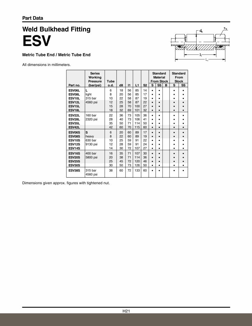
Weld Bulkhead Fitting
ESVMetric Tube End / Metric Tube End
All dimensions in millimeters.
Dimensions given approx. figures with tightened nut.
Series Standard StandardWorking Material FromPressure Tube From Stock Stock
Part no. (bar/psi) o.d. d8 I1 L1 S2 S SS B S SS
ESV06L L 6 18 56 85 14 • • • •ESV08L light 8 20 56 85 17 • • • •ESV10L 315 bar 10 22 58 87 19 • • • •ESV12L 4560 psi 12 25 58 87 22 • • • •ESV15L 15 28 70 100 27 • • • •ESV18L 18 32 69 101 32 • • • •
ESV22L 160 bar 22 36 73 105 36 • • • •ESV28L 2320 psi 28 40 73 106 41 • • • •ESV35L 35 50 71 114 50 • • • •ESV42L 42 60 70 115 60 • • • •
ESV06S S 6 20 60 89 17 • • • •ESV08S heavy 8 22 60 89 19 • • • •ESV10S 630 bar 10 25 59 91 22 • • • •ESV12S 9130 psi 12 28 59 91 24 • • • •ESV14S 14 30 72 107 27 • • • •
ESV16S 400 bar 16 35 71 107 30 • • • •ESV20S 5800 psi 20 38 71 114 36 • • • •ESV25S 25 45 72 120 46 • • • •ESV30S 30 50 73 126 50 • • • •
ESV38S 315 bar 38 60 72 133 60 • • • •4560 psi
H22
Part Data
H
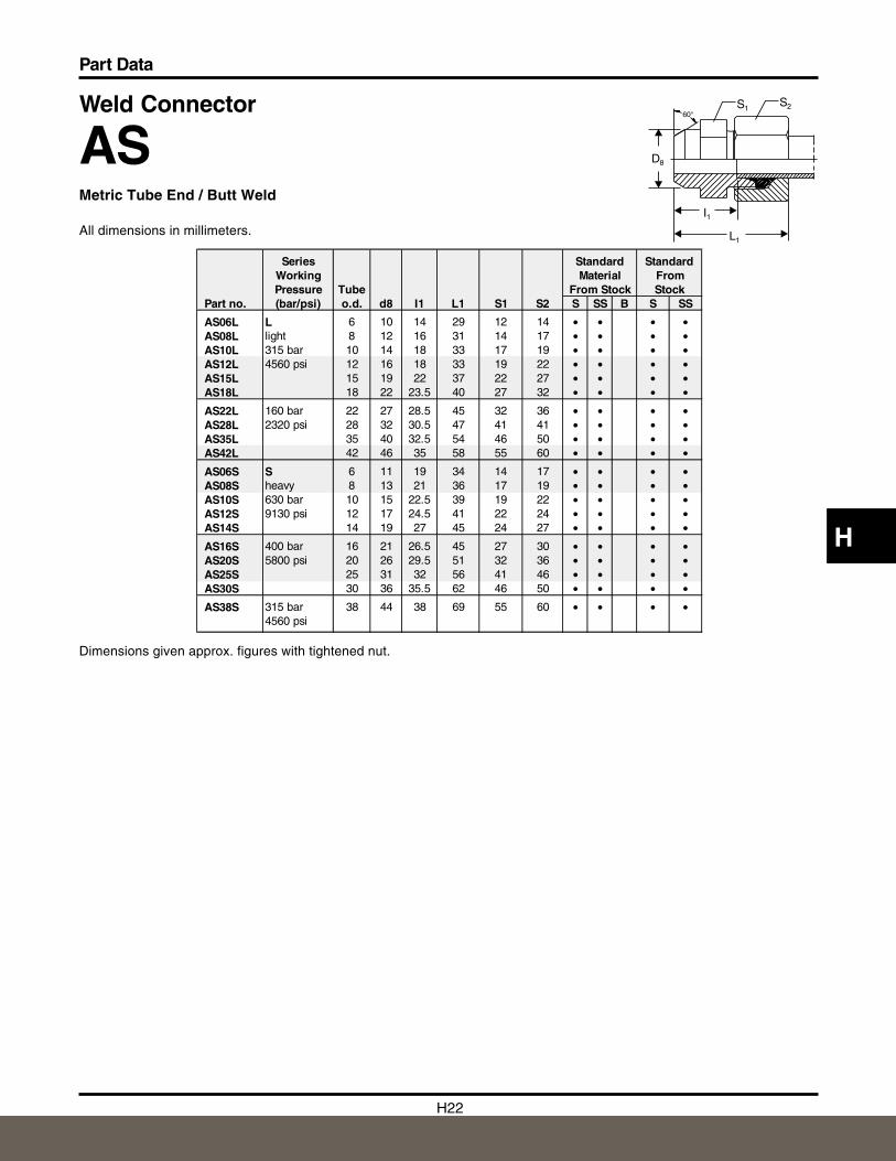
Weld Connector
ASMetric Tube End / Butt Weld
All dimensions in millimeters.
Dimensions given approx. figures with tightened nut.
Series Standard StandardWorking Material FromPressure Tube From Stock Stock
Part no. (bar/psi) o.d. d8 I1 L1 S1 S2 S SS B S SS
AS06L L 6 10 14 29 12 14 • • • •AS08L light 8 12 16 31 14 17 • • • •AS10L 315 bar 10 14 18 33 17 19 • • • •AS12L 4560 psi 12 16 18 33 19 22 • • • •AS15L 15 19 22 37 22 27 • • • •AS18L 18 22 23.5 40 27 32 • • • •
AS22L 160 bar 22 27 28.5 45 32 36 • • • •AS28L 2320 psi 28 32 30.5 47 41 41 • • • •AS35L 35 40 32.5 54 46 50 • • • •AS42L 42 46 35 58 55 60 • • • •
AS06S S 6 11 19 34 14 17 • • • •AS08S heavy 8 13 21 36 17 19 • • • •AS10S 630 bar 10 15 22.5 39 19 22 • • • •AS12S 9130 psi 12 17 24.5 41 22 24 • • • •AS14S 14 19 27 45 24 27 • • • •
AS16S 400 bar 16 21 26.5 45 27 30 • • • •AS20S 5800 psi 20 26 29.5 51 32 36 • • • •AS25S 25 31 32 56 41 46 • • • •AS30S 30 36 35.5 62 46 50 • • • •
AS38S 315 bar 38 44 38 69 55 60 • • • •4560 psi
S1
D8
I1
L1
S260°
H23
Part Data
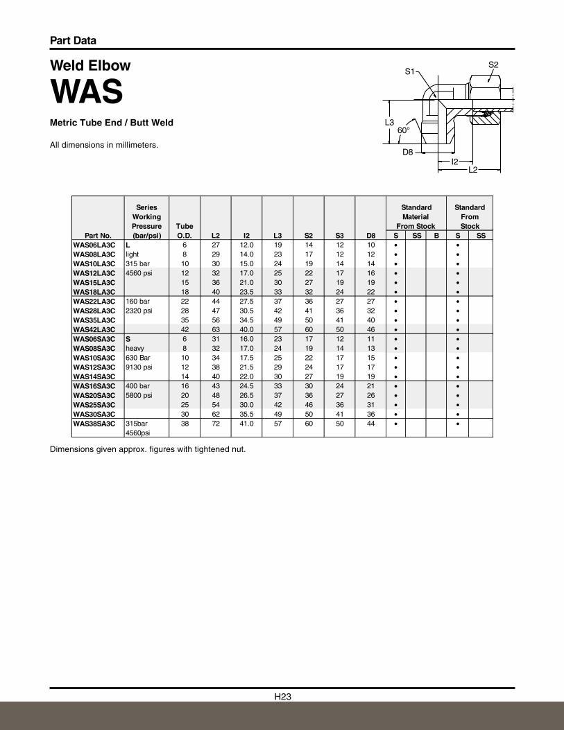
Weld Elbow
WASMetric Tube End / Butt Weld
All dimensions in millimeters.
S2S1
L360°
D8I2
L2
MaterialTube From Stock
Part No. O.D. L2 I2 L3 S2 S3 D8 S SS B S SSWAS06LA3C L 6 27 12.0 19 14 12 10 • •WAS08LA3C light 8 29 14.0 23 17 12 12 • •WAS10LA3C 315 bar 10 30 15.0 24 19 14 14 • •WAS12LA3C 4560 psi 12 32 17.0 25 22 17 16 • •WAS15LA3C 15 36 21.0 30 27 19 19 • •WAS18LA3C 18 40 23.5 33 32 24 22 • •WAS22LA3C 160 bar 22 44 27.5 37 36 27 27 • •WAS28LA3C 2320 psi 28 47 30.5 42 41 36 32 • •WAS35LA3C 35 56 34.5 49 50 41 40 • •WAS42LA3C 42 63 40.0 57 60 50 46 • •WAS06SA3C S 6 31 16.0 23 17 12 11 • •WAS08SA3C heavy 8 32 17.0 24 19 14 13 • •WAS10SA3C 630 Bar 10 34 17.5 25 22 17 15 • •WAS12SA3C 9130 psi 12 38 21.5 29 24 17 17 • •WAS14SA3C 14 40 22.0 30 27 19 19 • •WAS16SA3C 400 bar 16 43 24.5 33 30 24 21 • •WAS20SA3C 5800 psi 20 48 26.5 37 36 27 26 • •WAS25SA3C 25 54 30.0 42 46 36 31 • •WAS30SA3C 30 62 35.5 49 50 41 36 • •WAS38SA3C 315bar
4560psi38 72 41.0 57 60 50 44 • •
Stock
Series Working Pressure (bar/psi)
Standard StandardFrom
Dimensions given approx. figures with tightened nut.
H24
Part Data
H
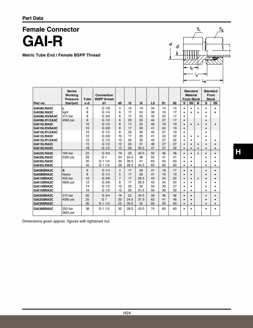
Female Connector
GAI-RMetric Tube End / Female BSPP Thread
Dimensions given approx. figures with tightened nut.
Series Standard StandardWorking Connection Material FromPressure Tube BSPP thread From Stock Stock
Part no. (bar/psi) o.d. d1 d5 I2 I5 L5 S1 S2 S SS B S SS
GAI06LRA3C L 6 G 1/8 4 12 19 34 14 14 • • • • •GAI08LRA3C light 8 G 1/4 6 17 24 39 19 17 • • • • •GAI08LR3/8A3C 315 bar 8 G 3/8 6 17 25 40 24 17 • •GAI08LR1/2A3C 4560 psi 8 G 1/2 6 20 29 44 27 17 • •GAI10LRA3C 10 G 1/4 8 17 25 40 19 19 • • • • •GAI10LR3/8A3C 10 G 3/8 8 17 26 41 24 19 • •GAI10LR1/2A3C 10 G 1/2 8 20 30 45 27 19 • •GAI12LRA3C 12 G 3/8 10 17 26 41 24 22 • • • •GAI12LR1/2A3C 12 G 1/2 10 20 30 45 27 22 • • • •GAI15LRA3C 15 G 1/2 12 20 31 46 27 27 • • • • •GAI18LRA3C 18 G 1/2 15 20 30.5 47 27 32 • • • • •
GAI22LRA3C 160 bar 22 G 3/4 19 22 35.5 52 36 36 • • • • •GAI28LRA3C 2320 psi 28 G 1 24 24.5 38 55 41 41 • • • •GAI35LRA3C 35 G 1 1/4 30 26.5 41 63 55 50 • • • •GAI42LRA3C 42 G 1 1/2 36 28.5 42.5 65 60 60 • • • •
GAI06SRA3C S 6 G 1/4 4 17 26 41 19 17 • • • •GAI08SRA3C heavy 8 G 1/4 5 17 26 41 19 19 • • • •GAI10SRA3C 400 bar 10 G 3/8 7 17 26.5 43 24 22 • • • • •GAI12SRA3C 5800 psi 12 G 3/8 8 17 26.5 43 24 24 • • • •GAI14SRA3C 14 G 1/2 10 20 32 50 30 27 • • • •GAI16SRA3C 16 G 1/2 12 20 31.5 50 30 30 • • • •
GAI20SRA3C 315 bar 20 G 3/4 16 22 34.5 56 36 36 • • • •GAI25SRA3C 4560 psi 25 G 1 20 24.5 37.5 62 41 46 • • • •GAI30SRA3C 30 G 1 1/4 25 26.5 42 69 55 50 • • • •
GAI38SRA3C 250 bar 38 G 1 1/2 32 28.5 43.5 74 60 60 • • • •3625 psi
H25
Part Data
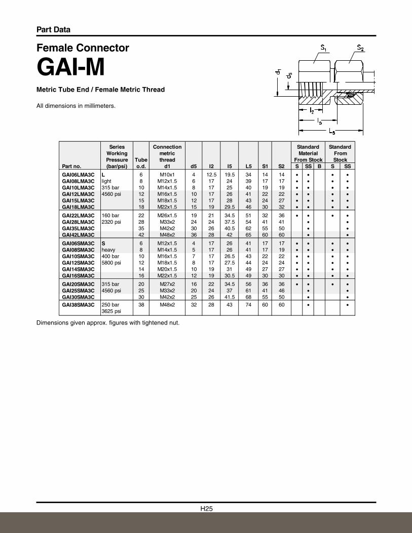
Female Connector
GAI-MMetric Tube End / Female Metric Thread
All dimensions in millimeters.
Dimensions given approx. figures with tightened nut.
Series Connection Standard StandardWorking metric Material FromPressure Tube thread From Stock Stock
Part no. (bar/psi) o.d. d1 d5 I2 I5 L5 S1 S2 S SS B S SS
GAI06LMA3C L 6 M10x1 4 12.5 19.5 34 14 14 • • • •GAI08LMA3C light 8 M12x1.5 6 17 24 39 17 17 • • • •GAI10LMA3C 315 bar 10 M14x1.5 8 17 25 40 19 19 • • • •GAI12LMA3C 4560 psi 12 M16x1.5 10 17 26 41 22 22 • • • •GAI15LMA3C 15 M18x1.5 12 17 28 43 24 27 • • • •GAI18LMA3C 18 M22x1.5 15 19 29.5 46 30 32 • • • •
GAI22LMA3C 160 bar 22 M26x1.5 19 21 34.5 51 32 36 • • • •GAI28LMA3C 2320 psi 28 M33x2 24 24 37.5 54 41 41 • •GAI35LMA3C 35 M42x2 30 26 40.5 62 55 50 • •GAI42LMA3C 42 M48x2 36 28 42 65 60 60 • •
GAI06SMA3C S 6 M12x1.5 4 17 26 41 17 17 • • • •GAI08SMA3C heavy 8 M14x1.5 5 17 26 41 17 19 • • • •GAI10SMA3C 400 bar 10 M16x1.5 7 17 26.5 43 22 22 • • • •GAI12SMA3C 5800 psi 12 M18x1.5 8 17 27.5 44 24 24 • • • •GAI14SMA3C 14 M20x1.5 10 19 31 49 27 27 • • • •GAI16SMA3C 16 M22x1.5 12 19 30.5 49 30 30 • • • •
GAI20SMA3C 315 bar 20 M27x2 16 22 34.5 56 36 36 • • • •GAI25SMA3C 4560 psi 25 M33x2 20 24 37 61 41 46 • •GAI30SMA3C 30 M42x2 25 26 41.5 68 55 50 • •GAI38SMA3C 250 bar 38 M48x2 32 28 43 74 60 60 • •
3625 psi
H26
Part Data
H
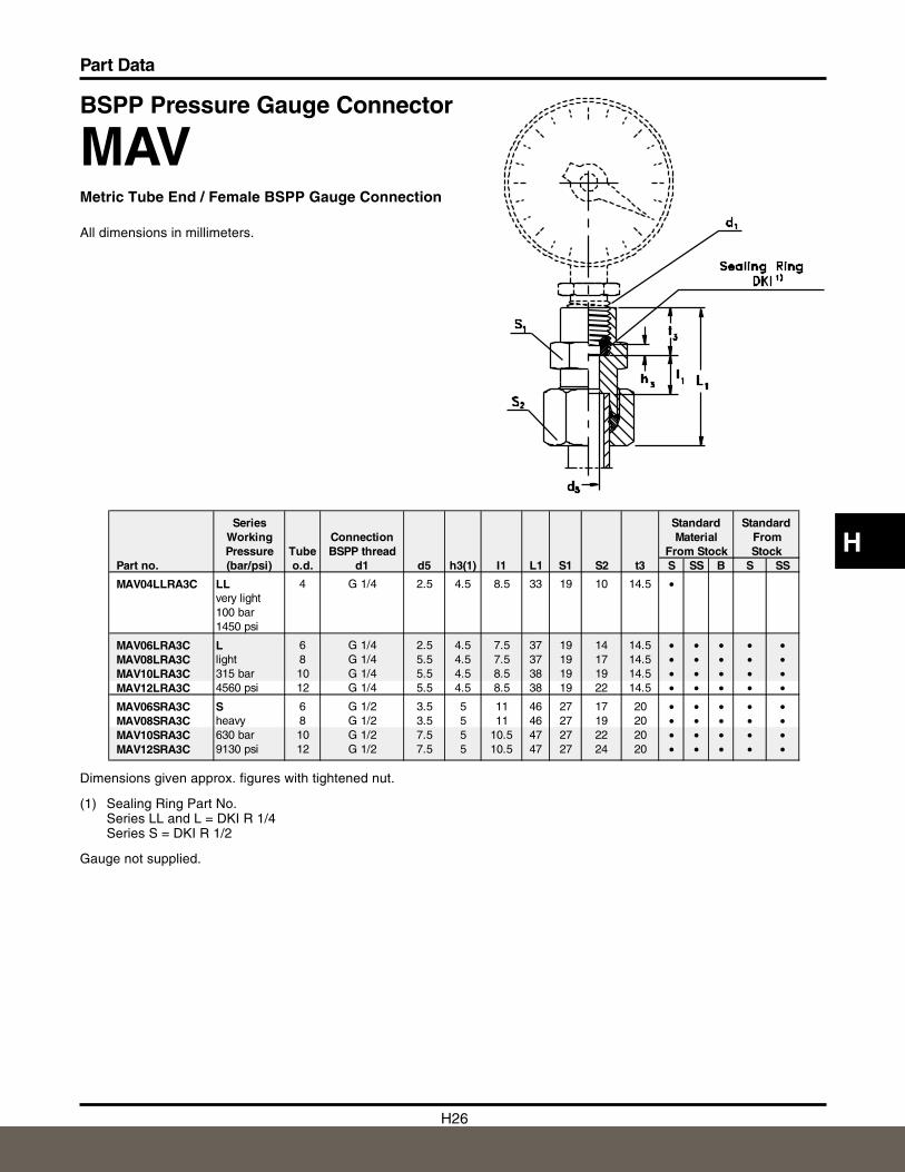
BSPP Pressure Gauge Connector
MAVMetric Tube End / Female BSPP Gauge Connection
All dimensions in millimeters.
Dimensions given approx. figures with tightened nut.
(1) Sealing Ring Part No.Series LL and L = DKI R 1/4Series S = DKI R 1/2
Gauge not supplied.
Series Standard StandardWorking Connection Material FromPressure Tube BSPP thread From Stock Stock
Part no. (bar/psi) o.d. d1 d5 h3(1) I1 L1 S1 S2 t3 S SS B S SS
MAV04LLRA3C LL 4 G 1/4 2.5 4.5 8.5 33 19 10 14.5 •very light100 bar1450 psi
MAV06LRA3C L 6 G 1/4 2.5 4.5 7.5 37 19 14 14.5 • • • • •MAV08LRA3C light 8 G 1/4 5.5 4.5 7.5 37 19 17 14.5 • • • • •MAV10LRA3C 315 bar 10 G 1/4 5.5 4.5 8.5 38 19 19 14.5 • • • • •MAV12LRA3C 4560 psi 12 G 1/4 5.5 4.5 8.5 38 19 22 14.5 • • • • •
MAV06SRA3C S 6 G 1/2 3.5 5 11 46 27 17 20 • • • • •MAV08SRA3C heavy 8 G 1/2 3.5 5 11 46 27 19 20 • • • • •MAV10SRA3C 630 bar 10 G 1/2 7.5 5 10.5 47 27 22 20 • • • • •MAV12SRA3C 9130 psi 12 G 1/2 7.5 5 10.5 47 27 24 20 • • • • •
H27
Part Data
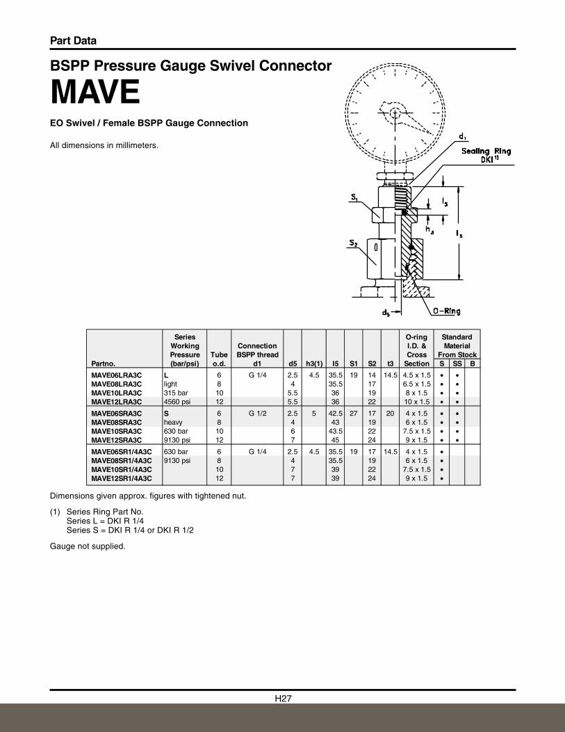
BSPP Pressure Gauge Swivel Connector
MAVEEO Swivel / Female BSPP Gauge Connection
All dimensions in millimeters.
Dimensions given approx. figures with tightened nut.
(1) Series Ring Part No.Series L = DKI R 1/4Series S = DKI R 1/4 or DKI R 1/2
Gauge not supplied.
Series O-ring StandardWorking Connection I.D. & MaterialPressure Tube BSPP thread Cross From Stock
Partno. (bar/psi) o.d. d1 d5 h3(1) I5 S1 S2 t3 Section S SS B
MAVE06LRA3C L 6 G 1/4 2.5 4.5 35.5 19 14 14.5 4.5 x 1.5 • •MAVE08LRA3C light 8 4 35.5 17 6.5 x 1.5 • •MAVE10LRA3C 315 bar 10 5.5 36 19 8 x 1.5 • •MAVE12LRA3C 4560 psi 12 5.5 36 22 10 x 1.5 • •
MAVE06SRA3C S 6 G 1/2 2.5 5 42.5 27 17 20 4 x 1.5 • •MAVE08SRA3C heavy 8 4 43 19 6 x 1.5 • •MAVE10SRA3C 630 bar 10 6 43.5 22 7.5 x 1.5 • •MAVE12SRA3C 9130 psi 12 7 45 24 9 x 1.5 • •
MAVE06SR1/4A3C 630 bar 6 G 1/4 2.5 4.5 35.5 19 17 14.5 4 x 1.5 •MAVE08SR1/4A3C 9130 psi 8 4 35.5 19 6 x 1.5 •MAVE10SR1/4A3C 10 7 39 22 7.5 x 1.5 •MAVE12SR1/4A3C 12 7 39 24 9 x 1.5 •

H28
Part Data
H
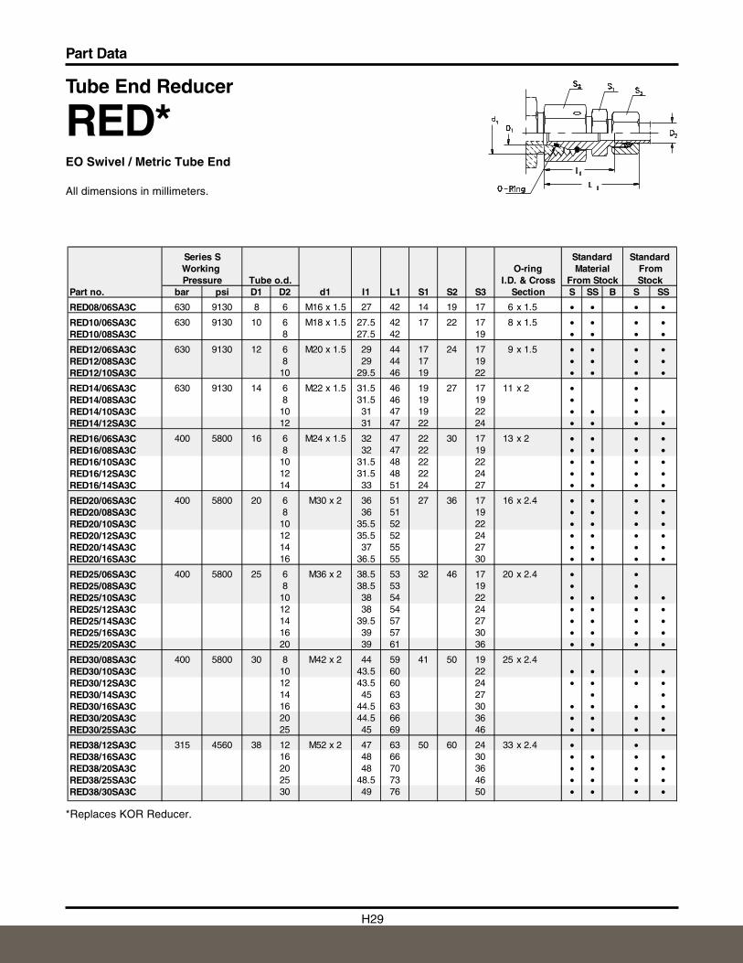
Tube End Reducer
RED*EO Swivel / Metric Tube End
All dimensions in millimeters.
*Replaces KOR Reducer.Series S continued on page H50.
Series L Standard StandardWorking Tube O-ring Material FromPressure o.d. I.D. & Cross From Stock Stock
Part no. bar psi D1 D2 d1 I1 L1 S1 S2 S3 Section S SS B S SS
RED06L/04LLA3C 250 3625 6 4 M12 x 1.5 24.5 34 9 14 10 4.5 x 1.5 •
RED08/06LA3C 315 4560 8 6 M14 x 1.5 23.5 38 12 17 14 6.5 x 1.5 • • • •
RED10/06LA3C 315 4560 10 6 M16 x 1.5 25 40 14 19 14 8 x 1.5 • • • •RED10/08LA3C 8 25 40 17 • • • •
RED12/06LA3C 315 4560 12 6 M18 x 1.5 25 40 17 22 14 10 x 1.5 • • • •RED12/08LA3C 8 25 40 17 • • • •RED12/10LA3C 10 26 41 19 • • • •
RED15/06LA3C 315 4560 15 6 M22 x 1.5 28.5 43 19 27 14 12 x 2 • • • •RED15/08LA3C 8 28.5 43 17 • • • •RED15/10LA3C 10 29.5 44 19 • • • •RED15/12LA3C 12 29.5 44 22 • • • •
RED18/06LA3C 315 4560 18 6 M26 x 1.5 28 43 24 32 14 15 x 2 • • •RED18/08LA3C 8 28 43 17 • • • •RED18/10LA3C 10 29 44 19 • • • •RED18/12LA3C 12 29 44 22 • • • •RED18/15LA3C 15 30 45 27 • • • •
RED22/06LA3C 160 2320 22 6 M30 x 2 32 47 27 36 14 20 x 2 • • • •RED22/08LA3C 8 32 47 17 • • • •RED22/10LA3C 10 33 48 19 • • • •RED22/12LA3C 12 33 48 22 • • • •RED22/15LA3C 15 34 49 27 • • • •RED22/18LA3C 18 33.5 50 32 • • • •
RED28/06LA3C 160 2320 28 6 M36 x 2 34 49 32 41 14 26 x 2 • •RED28/08LA3C 8 34 49 17 • •RED28/10LA3C 10 35 50 19 • • • •RED28/12LA3C 12 35 50 22 • • • •RED28/15LA3C 15 36 51 27 • • • •RED28/18LA3C 18 35.5 52 32 • • • •RED28/22LA3C 22 37.5 54 36 • • • •
RED35/12LA3C 160 2320 35 12 M45 x 2 38 53 41 50 22 32 x 2.5 • •RED35/15LA3C 15 39 54 27 • • • •RED35/18LA3C 18 38.5 55 32 • • • •RED35/22LA3C 22 40.5 57 36 • • • •RED35/28LA3C 28 40.5 57 41 • • • •
RED42/18LA3C 160 2320 42 18 M52 x 2 42 58 50 60 32 38 x 2.5 • •RED42/22LA3C 22 44 60 36 • • • •RED42/28LA3C 28 44 61 41 • • • •RED42/35LA3C 35 43 65 50 • • • •
H29
Part Data
Tube End Reducer
RED*EO Swivel / Metric Tube End
All dimensions in millimeters.
*Replaces KOR Reducer.
Series S Standard StandardWorking O-ring Material FromPressure Tube o.d. I.D. & Cross From Stock Stock
Part no. bar psi D1 D2 d1 I1 L1 S1 S2 S3 Section S SS B S SS
RED08/06SA3C 630 9130 8 6 M16 x 1.5 27 42 14 19 17 6 x 1.5 • • • •
RED10/06SA3C 630 9130 10 6 M18 x 1.5 27.5 42 17 22 17 8 x 1.5 • • • •RED10/08SA3C 8 27.5 42 19 • • • •
RED12/06SA3C 630 9130 12 6 M20 x 1.5 29 44 17 24 17 9 x 1.5 • • • •RED12/08SA3C 8 29 44 17 19 • • • •RED12/10SA3C 10 29.5 46 19 22 • • • •
RED14/06SA3C 630 9130 14 6 M22 x 1.5 31.5 46 19 27 17 11 x 2 • •RED14/08SA3C 8 31.5 46 19 19 • •RED14/10SA3C 10 31 47 19 22 • • • •RED14/12SA3C 12 31 47 22 24 • • • •
RED16/06SA3C 400 5800 16 6 M24 x 1.5 32 47 22 30 17 13 x 2 • • • •RED16/08SA3C 8 32 47 22 19 • • • •RED16/10SA3C 10 31.5 48 22 22 • • • •RED16/12SA3C 12 31.5 48 22 24 • • • •RED16/14SA3C 14 33 51 24 27 • • • •
RED20/06SA3C 400 5800 20 6 M30 x 2 36 51 27 36 17 16 x 2.4 • • • •RED20/08SA3C 8 36 51 19 • • • •RED20/10SA3C 10 35.5 52 22 • • • •RED20/12SA3C 12 35.5 52 24 • • • •RED20/14SA3C 14 37 55 27 • • • •RED20/16SA3C 16 36.5 55 30 • • • •
RED25/06SA3C 400 5800 25 6 M36 x 2 38.5 53 32 46 17 20 x 2.4 • •RED25/08SA3C 8 38.5 53 19 • •RED25/10SA3C 10 38 54 22 • • • •RED25/12SA3C 12 38 54 24 • • • •RED25/14SA3C 14 39.5 57 27 • • • •RED25/16SA3C 16 39 57 30 • • • •RED25/20SA3C 20 39 61 36 • • • •
RED30/08SA3C 400 5800 30 8 M42 x 2 44 59 41 50 19 25 x 2.4RED30/10SA3C 10 43.5 60 22 • • • •RED30/12SA3C 12 43.5 60 24 • • • •RED30/14SA3C 14 45 63 27 • •RED30/16SA3C 16 44.5 63 30 • • • •RED30/20SA3C 20 44.5 66 36 • • • •RED30/25SA3C 25 45 69 46 • • • •
RED38/12SA3C 315 4560 38 12 M52 x 2 47 63 50 60 24 33 x 2.4 • •RED38/16SA3C 16 48 66 30 • • • •RED38/20SA3C 20 48 70 36 • • • •RED38/25SA3C 25 48.5 73 46 • • • •RED38/30SA3C 30 49 76 50 • • • •
H30
Part Data
H
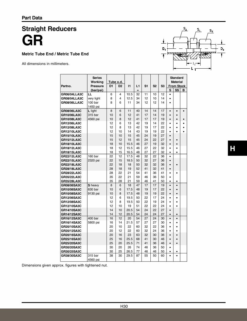
Straight Reducers
GRMetric Tube End / Metric Tube End
All dimensions in millimeters.
Dimensions given approx. figures with tightened nut.
Series StandardWorking Tube o.d. Material
Partno. Pressure D1 D2 I1 L1 S1 S2 S3 From Stock(bar/psi) ≈≈≈ S SS B
GR06/04LLA3C LL 6 4 10.5 32 11 10 12 •GR08/04LLA3C very light 8 4 12.5 34 12 10 14 •GR08/06LLA3C 100 bar 8 6 11 34 12 12 14 •
1450 psiGR08/06LA3C L light 8 6 11 40 14 14 17 • • •GR10/06LA3C 315 bar 10 6 12 41 17 14 19 • •GR10/08LA3C 4560 psi 10 8 12 41 17 17 19 • • •GR12/06LA3C 12 6 13 42 19 14 22 • • •GR12/08LA3C 12 8 13 42 19 17 22 • • •GR12/10LA3C 12 10 14 43 19 19 22 • • •GR15/10LA3C 15 10 15 45 24 19 27 •GR15/12LA3C 15 12 15 45 24 22 27 • •GR18/10LA3C 18 10 15.5 46 27 19 32 • •GR18/12LA3C 18 12 15.5 46 27 22 32 • •GR18/15LA3C 18 15 16.5 48 27 27 32 • •GR22/12LA3C 160 bar 22 12 17.5 48 32 22 36 •GR22/15LA3C 2320 psi 22 15 18.5 50 32 27 36 •GR22/18LA3C 22 18 18 50 32 32 36 • •GR28/18LA3C 28 18 19 52 41 32 41 •GR28/22LA3C 28 22 21 54 41 36 41 • •GR35/22LA3C 35 22 21 59 46 36 50 •GR35/28LA3C 35 28 21 59 46 41 50 • •GR08/06SA3C S heavy 8 6 18 47 17 17 19 • •GR10/06SA3C 630 bar 10 6 17.5 48 19 17 22 • •GR10/08SA3C 9130 psi 10 8 17.5 48 19 19 22 • •GR12/06SA3C 12 6 19.5 50 22 17 24 • •GR12/08SA3C 12 8 19.5 50 22 19 24 • •GR12/10SA3C 12 10 19 51 22 22 24 • •GR14/10SA3C 14 10 20.5 54 24 22 27 •GR14/12SA3C 14 12 20.5 54 24 24 27 • •GR16/12SA3C 400 bar 16 12 20 54 27 24 30 • •GR16/14SA3C 5800 psi 16 14 21.5 57 27 27 30 • •GR20/10SA3C 20 10 22 60 32 22 36 • •GR20/12SA3C 20 12 22 60 32 24 36 • •GR20/16SA3C 20 16 23 63 32 30 36 • •GR25/16SA3C 25 16 25.5 68 41 30 46 • •GR25/20SA3C 25 20 25.5 71 41 36 46 • •GR30/20SA3C 30 20 26 74 46 36 50 •GR30/25SA3C 30 25 26.5 77 46 46 50 • •GR38/30SA3C 315 bar 38 30 29.5 87 55 50 60 • •
4560 psi
H31
Part Data
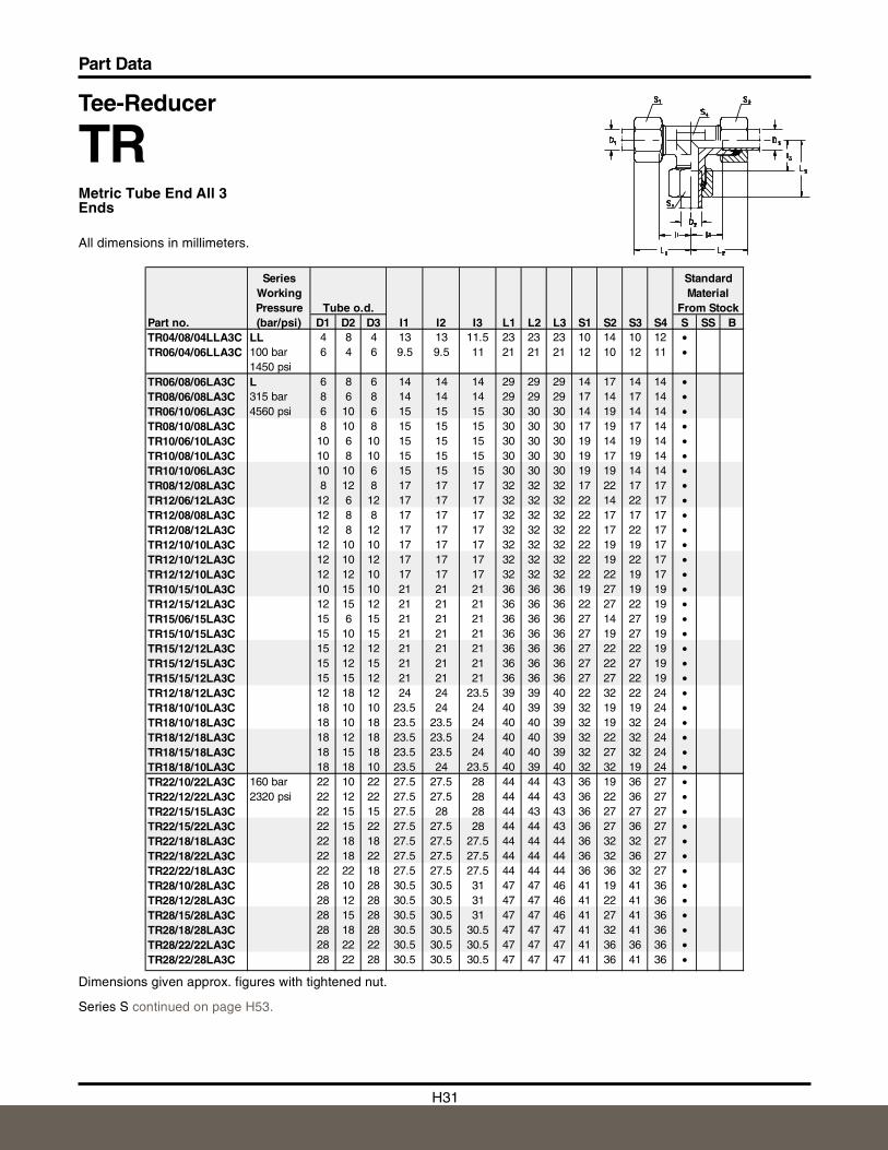
Tee-Reducer
TRMetric Tube End All 3 Ends
All dimensions in millimeters.
Dimensions given approx. figures with tightened nut.
Series S continued on page H53.
Series StandardWorking MaterialPressure Tube o.d. From Stock
Part no. (bar/psi) D1 D2 D3 I1 I2 I3 L1 L2 L3 S1 S2 S3 S4 S SS BTR04/08/04LLA3C LL 4 8 4 13 13 11.5 23 23 23 10 14 10 12 •TR06/04/06LLA3C 100 bar 6 4 6 9.5 9.5 11 21 21 21 12 10 12 11 •
1450 psiTR06/08/06LA3C L 6 8 6 14 14 14 29 29 29 14 17 14 14 •TR08/06/08LA3C 315 bar 8 6 8 14 14 14 29 29 29 17 14 17 14 •TR06/10/06LA3C 4560 psi 6 10 6 15 15 15 30 30 30 14 19 14 14 •TR08/10/08LA3C 8 10 8 15 15 15 30 30 30 17 19 17 14 •TR10/06/10LA3C 10 6 10 15 15 15 30 30 30 19 14 19 14 •TR10/08/10LA3C 10 8 10 15 15 15 30 30 30 19 17 19 14 •TR10/10/06LA3C 10 10 6 15 15 15 30 30 30 19 19 14 14 •TR08/12/08LA3C 8 12 8 17 17 17 32 32 32 17 22 17 17 •TR12/06/12LA3C 12 6 12 17 17 17 32 32 32 22 14 22 17 •TR12/08/08LA3C 12 8 8 17 17 17 32 32 32 22 17 17 17 •TR12/08/12LA3C 12 8 12 17 17 17 32 32 32 22 17 22 17 •TR12/10/10LA3C 12 10 10 17 17 17 32 32 32 22 19 19 17 •TR12/10/12LA3C 12 10 12 17 17 17 32 32 32 22 19 22 17 •TR12/12/10LA3C 12 12 10 17 17 17 32 32 32 22 22 19 17 •TR10/15/10LA3C 10 15 10 21 21 21 36 36 36 19 27 19 19 •TR12/15/12LA3C 12 15 12 21 21 21 36 36 36 22 27 22 19 •TR15/06/15LA3C 15 6 15 21 21 21 36 36 36 27 14 27 19 •TR15/10/15LA3C 15 10 15 21 21 21 36 36 36 27 19 27 19 •TR15/12/12LA3C 15 12 12 21 21 21 36 36 36 27 22 22 19 •TR15/12/15LA3C 15 12 15 21 21 21 36 36 36 27 22 27 19 •TR15/15/12LA3C 15 15 12 21 21 21 36 36 36 27 27 22 19 •TR12/18/12LA3C 12 18 12 24 24 23.5 39 39 40 22 32 22 24 •TR18/10/10LA3C 18 10 10 23.5 24 24 40 39 39 32 19 19 24 •TR18/10/18LA3C 18 10 18 23.5 23.5 24 40 40 39 32 19 32 24 •TR18/12/18LA3C 18 12 18 23.5 23.5 24 40 40 39 32 22 32 24 •TR18/15/18LA3C 18 15 18 23.5 23.5 24 40 40 39 32 27 32 24 •TR18/18/10LA3C 18 18 10 23.5 24 23.5 40 39 40 32 32 19 24 •TR22/10/22LA3C 160 bar 22 10 22 27.5 27.5 28 44 44 43 36 19 36 27 •TR22/12/22LA3C 2320 psi 22 12 22 27.5 27.5 28 44 44 43 36 22 36 27 •TR22/15/15LA3C 22 15 15 27.5 28 28 44 43 43 36 27 27 27 •TR22/15/22LA3C 22 15 22 27.5 27.5 28 44 44 43 36 27 36 27 •TR22/18/18LA3C 22 18 18 27.5 27.5 27.5 44 44 44 36 32 32 27 •TR22/18/22LA3C 22 18 22 27.5 27.5 27.5 44 44 44 36 32 36 27 •TR22/22/18LA3C 22 22 18 27.5 27.5 27.5 44 44 44 36 36 32 27 •TR28/10/28LA3C 28 10 28 30.5 30.5 31 47 47 46 41 19 41 36 •TR28/12/28LA3C 28 12 28 30.5 30.5 31 47 47 46 41 22 41 36 •TR28/15/28LA3C 28 15 28 30.5 30.5 31 47 47 46 41 27 41 36 •TR28/18/28LA3C 28 18 28 30.5 30.5 30.5 47 47 47 41 32 41 36 •TR28/22/22LA3C 28 22 22 30.5 30.5 30.5 47 47 47 41 36 36 36 •TR28/22/28LA3C 28 22 28 30.5 30.5 30.5 47 47 47 41 36 41 36 •

H32
Part Data
H
Tee-Reducer
TRMetric Tube End All 3 Ends
All dimensions in millimeters.
Dimensions given approx. figures with tightened nut.
Series StandardWorking MaterialPressure Tube o.d. From Stock
Part no. (bar/psi) D1 D2 D3 I1 I2 I3 L1 L2 L3 S1 S2 S3 S4 S SS BTR10/06/10SA3C S 10 6 10 17.5 17.5 18 34 34 33 22 17 22 17 •TR12/08/08SA3C 630 bar 12 8 8 21.5 22 22 38 37 37 24 19 19 17 •TR12/08/12SA3C 9130 psi 12 8 12 21.5 21.5 22 38 38 37 24 19 24 17 •TR12/10/12SA3C 12 10 12 21.5 21.5 21.5 38 38 38 24 22 24 17 •TR12/16/12SA3C 400 bar 12 16 12 25.5 25.5 24.5 42 42 43 24 30 24 24 •TR16/06/16SA3C 5800 psi 16 6 16 24.5 24.5 26 43 43 41 30 17 30 24 •TR16/08/16SA3C 16 8 16 24.5 24.5 26 43 43 41 30 19 30 24 •TR16/10/16SA3C 16 10 16 24.5 24.5 25.5 43 43 42 30 22 30 24 •TR16/12/16SA3C 16 12 16 24.5 24.5 25.5 43 43 42 30 24 30 24 •TR16/20/16SA3C 16 20 16 28.5 28.5 26.5 47 47 48 30 36 30 27 •TR20/10/20SA3C 20 10 20 26.5 26.5 29.5 48 48 46 36 22 36 27 •TR20/12/20SA3C 20 12 20 26.5 26.5 29.5 48 48 46 36 24 6 27 •TR20/16/20SA3C 20 16 20 26.5 26.5 28.5 48 48 47 36 30 36 27 •TR20/25/20SA3C 20 25 20 31.5 31.5 30 53 53 54 36 46 36 36 •TR25/16/25SA3C 25 16 25 30 30 33.5 54 54 52 46 30 46 36 •TR25/20/25SA3C 25 20 25 30 30 31.5 54 54 53 46 36 46 36 •TR25/30/25SA3C 25 30 25 37 37 35.5 61 61 62 46 50 46 41 •
H33
Part Data
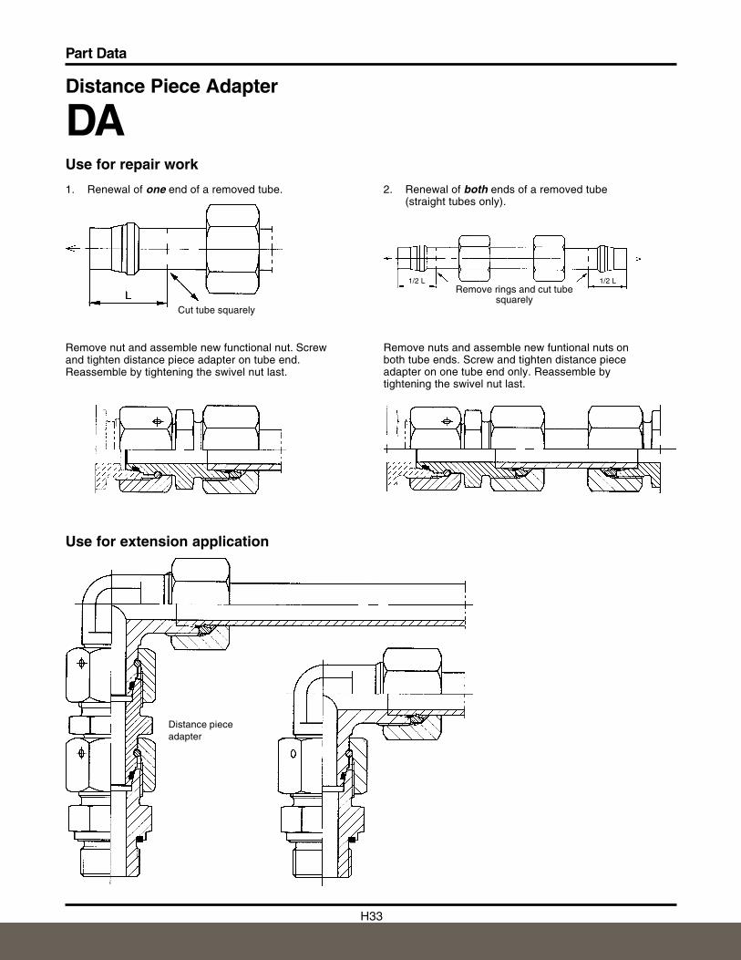
Distance Piece Adapter
DAUse for repair work
Use for extension application
Remove nuts and assemble new funtional nuts on both tube ends. Screw and tighten distance pieceadapter on one tube end only. Reassemble by tightening the swivel nut last.
Remove nut and assemble new functional nut. Screw and tighten distance piece adapter on tube end.Reassemble by tightening the swivel nut last.
2. Renewal of both ends of a removed tube(straight tubes only).
1. Renewal of one end of a removed tube.
Remove rings and cut tubesquarely
1/2 L 1/2 L
Distance pieceadapter
Cut tube squarely
H34
Part Data
H
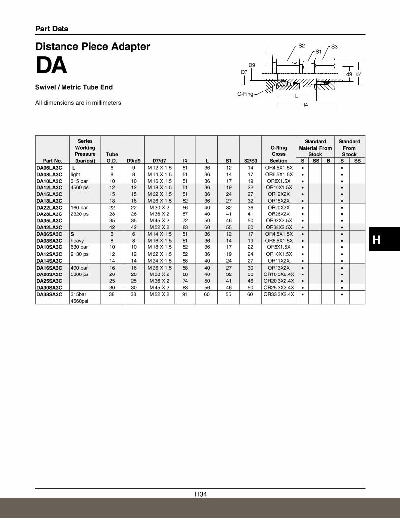
Distance Piece Adapter
DASwivel / Metric Tube End
All dimensions are in millimeters
S2S1
S3
d9 d7
I4
LO-Ring
D7D9
TubeO.D. D9/d9 D7/d7 I4 L S1 S2/S3 S SS B S SS
DA06LA3C L 6 9 M 12 X 1.5 51 36 12 14 OR4.5X1.5X • •DA08LA3C light 8 8 M 14 X 1.5 51 36 14 17 OR6.5X1.5X • •DA10LA3C 315 bar 10 10 M 16 X 1.5 51 36 17 19 OR8X1.5X • •DA12LA3C 4560 psi 12 12 M 18 X 1.5 51 36 19 22 OR10X1.5X • •DA15LA3C 15 15 M 22 X 1.5 51 36 24 27 OR12X2X • • DA18LA3C 18 18 M 26 X 1.5 52 36 27 32 OR15X2X • •DA22LA3C 160 bar 22 22 M 30 X 2 56 40 32 36 OR20X2X • •DA28LA3C 2320 psi 28 28 M 36 X 2 57 40 41 41 OR26X2X • •DA35LA3C 35 35 M 45 X 2 72 50 46 50 OR32X2.5X • •DA42LA3C 42 42 M 52 X 2 83 60 55 60 OR38X2.5X • •DA06SA3C S 6 6 M 14 X 1.5 51 36 12 17 OR4.5X1.5X • •DA08SA3C heavy 8 8 M 16 X 1.5 51 36 14 19 OR6.5X1.5X • •DA10SA3C 630 bar 10 10 M 18 X 1.5 52 36 17 22 OR8X1.5X • •DA12SA3C 9130 psi 12 12 M 22 X 1.5 52 36 19 24 OR10X1.5X • •DA14SA3C 14 14 M 24 X 1.5 58 40 24 27 OR11X2X • •DA16SA3C 400 bar 16 16 M 26 X 1.5 58 40 27 30 OR13X2X • •DA20SA3C 5800 psi 20 20 M 30 X 2 68 46 32 36 OR16.3X2.4X • •DA25SA3C 25 25 M 36 X 2 74 50 41 46 OR20.3X2.4X • •DA30SA3C 30 30 M 45 X 2 83 56 46 50 OR25.3X2.4X • •DA38SA3C 315bar
4560psi38 38 M 52 X 2 91 60 55 60 OR33.3X2.4X • •
Standard From S tock
Part No.
Series Working Pressure (bar/psi)
O-Ring Cross
Section
Standard Material From
Stock
H35
Part Data
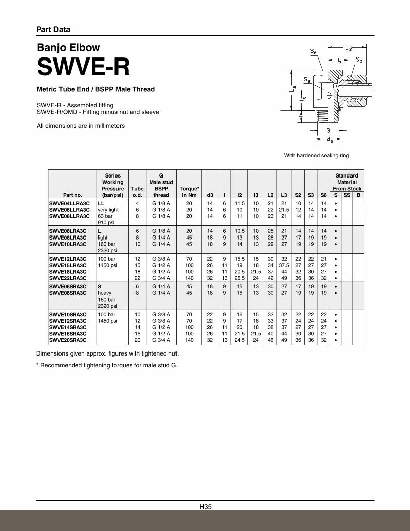
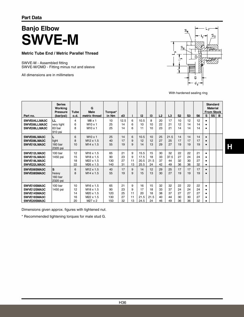
Banjo Elbow
SWVE-RMetric Tube End / BSPP Male Thread
SWVE-R - Assembled fittingSWVE-R/OMD - Fitting minus nut and sleeve
All dimensions are in millimeters
With hardened sealing ring
Dimensions given approx. figures with tightened nut.
* Recommended tightening torques for male stud G.
Series G StandardWorking Male stud MaterialPressure Tube BSPP Torque* From Stock
Part no. (bar/psi) o.d. thread in Nm d3 i I2 I3 L2 L3 S2 S3 S6 S SS B
SWVE04LLRA3C LL 4 G 1/8 A 20 14 6 11.5 10 21 21 10 14 14 •SWVE06LLRA3C very light 6 G 1/8 A 20 14 6 10 10 22 21.5 12 14 14 •SWVE08LLRA3C 63 bar 8 G 1/8 A 20 14 6 11 10 23 21 14 14 14 •
910 psi
SWVE06LRA3C L 6 G 1/8 A 20 14 6 10.5 10 25 21 14 14 14 •SWVE08LRA3C light 8 G 1/4 A 45 18 9 13 13 28 27 17 19 19 •SWVE10LRA3C 160 bar 10 G 1/4 A 45 18 9 14 13 29 27 19 19 19 •
2320 psi
SWVE12LRA3C 100 bar 12 G 3/8 A 70 22 9 15.5 15 30 32 22 22 21 •SWVE15LRA3C 1450 psi 15 G 1/2 A 100 26 11 19 18 34 37.5 27 27 27 •SWVE18LRA3C 18 G 1/2 A 100 26 11 20.5 21.5 37 44 32 30 27 •SWVE22LRA3C 22 G 3/4 A 140 32 13 25.5 24 42 49 36 36 32 •
SWVE06SRA3C S 6 G 1/4 A 45 18 9 15 13 30 27 17 19 19 •SWVE08SRA3C heavy 8 G 1/4 A 45 18 9 15 13 30 27 19 19 19 •
160 bar2320 psi
SWVE10SRA3C 100 bar 10 G 3/8 A 70 22 9 16 15 32 32 22 22 22 •SWVE12SRA3C 1450 psi 12 G 3/8 A 70 22 9 17 18 33 37 24 24 24 •SWVE14SRA3C 14 G 1/2 A 100 26 11 20 18 38 37 27 27 27 •SWVE16SRA3C 16 G 1/2 A 100 26 11 21.5 21.5 40 44 30 30 27 •SWVE20SRA3C 20 G 3/4 A 140 32 13 24.5 24 46 49 36 36 32 •
H36
Part Data
H
With hardened sealing ring
Banjo Elbow
SWVE-MMetric Tube End / Metric Parallel Thread
SWVE-M - Assembled fittingSWVE-M/OMD - Fitting minus nut and sleeve
All dimensions are in millimeters
Dimensions given approx. figures with tightened nut.
* Recommended tightening torques for male stud G.
Series StandardWorking G MaterialPressure Tube Male Torque* From Stock
Part no. (bar/psi) o.d. metric thread in Nm d3 i I2 I3 L2 L3 S2 S3 S6 S SS B
SWVE04LLMA3C LL 4 M8 x 1 10 12.5 6 10.5 8 20 17 10 12 12 •••SWVE06LLMA3C very light 6 M10 x 1 25 14 6 10 10 22 21 12 14 14 •••SWVE08LLMA3C 63 bar 8 M10 x 1 25 14 6 11 10 23 21 14 14 14 •••
910 psi
SWVE06LMA3C L 6 M10 x 1 25 14 6 10.5 10 25 21.5 14 14 14 •••SWVE08LMA3C light 8 M12 x 1.5 40 17 9 12 12 27 25 17 17 17 •••SWVE10LMA3C 160 bar 10 M14 x 1.5 55 19 9 14 13 29 27 19 19 19 •••
2320 psi
SWVE12LMA3C 100 bar 12 M16 x 1.5 65 21 9 15.5 15 30 32 22 22 21 •••SWVE15LMA3C 1450 psi 15 M18 x 1.5 90 23 9 17.5 18 33 37.5 27 24 24 •••SWVE18LMA3C 18 M22 x 1.5 130 27 11 20.5 21.5 37 44 32 30 27 •••SWVE22LMA3C 22 M26 x 1.5 140 31 13 25.5 24 42 49 36 36 32 •••
SWVE06SMA3C S 6 M12 x 1.5 40 17 9 14 12 29 25 17 17 17 •••SWVE08SMA3C heavy 8 M14 x 1.5 55 19 9 15 13 30 27 19 19 19 •••
160 bar2320 psi
SWVE10SMA3C 100 bar 10 M16 x 1.5 65 21 9 16 15 32 32 22 22 22 •••SWVE12SMA3C 1450 psi 12 M18 x 1.5 90 23 9 17 18 33 37 24 24 24 •••SWVE14SMA3C 14 M20 x 1.5 120 25 11 20 18 38 37 27 27 27 •••SWVE16SMA3C 16 M22 x 1.5 130 27 11 21.5 21.5 40 44 30 30 27 •••SWVE20SMA3C 20 M27 x 2 150 32 13 24.5 24 46 49 36 36 32 •••
H37
Part Data
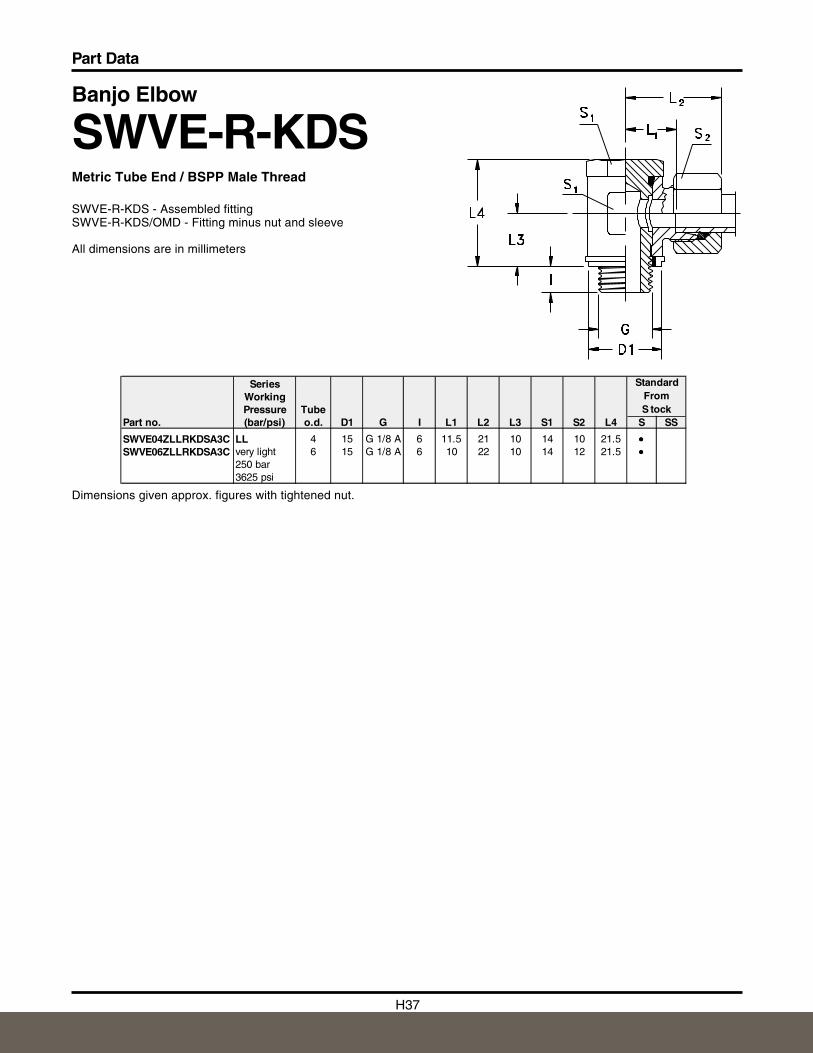
Banjo Elbow
SWVE-R-KDSMetric Tube End / BSPP Male Thread
SWVE-R-KDS - Assembled fittingSWVE-R-KDS/OMD - Fitting minus nut and sleeve
All dimensions are in millimeters
Dimensions given approx. figures with tightened nut.
SeriesWorkingPressure Tube
Part no. (bar/psi) o.d. D1 G I L1 L2 L3 S1 S2 L4 S SS
SWVE04ZLLRKDSA3C LL 4 15 G 1/8 A 6 11.5 21 10 14 10 21.5 •••SWVE06ZLLRKDSA3C very light 6 15 G 1/8 A 6 10 22 10 14 12 21.5 •••
250 bar3625 psi
Standard From S tock
H38
Part Data
H
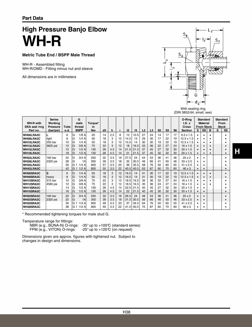
High Pressure Banjo Elbow
WH-RMetric Tube End / BSPP Male Thread
WH-R - Assembled fittingWH-R/OMD - Fitting minus nut and sleeve
All dimensions are in millimeters
With sealing ring (DIN 3852/d4, small, see)
* Recommended tightening torques for male stud G.
Temperature range for fittings:NBR (e.g., BUNA-N) O-rings: -35° up to +100°C (standard series)FPM (e.g., VITON) O-rings: -25° up to +120°C (on request)
Dimensions given are approx. figures with tightened nut. Subject tochanges in design and dimensions.
Series G O-Ring Standard StandardWH-R with Working male Torque* I.D. x Material From
DKA seal ring Pressure Tube thread in Cross From Stock StockPart no. (bar/psi) o.d. BSPP Nm d3 h i I2 I3 L2 L3 S2 S3 S6 Section S SS B S SS
WH06LRA3C L 6 G 1/8 A 20 14 2.5 8 12 10.5 27 24 14 17 17 9.3 x 1.5 • • • •WH08LRA3C light 8 G 1/4 A 50 18 3 12 14.5 14 29 30 17 22 19 12.5 x 1.5 • • • •WH10LRA3C 250 bar 10 G 1/4 A 50 18 3 12 15.5 14 30 30 19 22 19 12.5 x 1.5 • • • •WH12LRA3C 3625 psi 12 G 3/8 A 75 22 3 12 18 16.5 33 36 22 27 24 16 x 1.5 • • • •WH15LRA3C 15 G 1/2 A 130 26 4.5 14 21.5 21.5 37 45 27 32 30 20 x 1.5 • • • •WH18LRA3C 18 G 1/2 A 130 26 4.5 14 21 21.5 37 45 32 32 30 20 x 1.5 • • • •
WH22LRA3C 160 bar 22 G 3/4 A 250 32 3.5 16 27.5 24 44 53 36 41 36 25 x 2 • • •WH28LRA3C 2320 psi 28 G 1A 350 39 3.5 18 32 30.5 49 66 41 50 46 33 x 2.5 • • •WH35LRA3C 35 G 1 1/4 A 600 57 3.5 20 36 35.5 58 76 50 60 55 41 x 2.5 • • •WH42LRA3C 42 G 1 1/2 A 800 55 3.5 22 40.5 40.5 63 87 60 70 60 46 x 3 • • •
WH06SRA3C S 6 G 1/4 A 50 18 3 12 16.5 14 31 30 17 22 19 12.5 x 1.5 • • • •WH08SRA3C heavy 8 G 1/4 A 50 18 3 12 16.5 14 31 30 19 22 19 12.5 x 1.5 • • • •WH10SRA3C 315 bar 10 G 3/8 A 75 22 3 12 18.5 16.5 35 36 22 27 24 16 x 1.5 • • • •WH12SRA3C 4560 psi 12 G 3/8 A 75 22 3 12 18.5 16.5 35 36 24 27 24 16 x 1.5 • • • •WH14SRA3C 14 G 1/2 A 130 26 4.5 14 22.5 21.5 40 45 27 32 30 20 x 1.5 • • •WH16SRA3C 16 G 1/2 A 130 26 4.5 14 22 21.5 40 45 30 32 30 20 x 1.5 • • •
WH20SRA3C 160 bar 20 G 3/4 A 250 32 3.5 16 26.5 24 48 53 36 41 36 25 x 2 • • •WH25SRA3C 2320 psi 25 G 1A 350 39 3.5 18 31.5 30.5 56 66 46 50 46 33 x 2.5 • • •WH30SRA3C 30 G 1 1/4 A 600 49 3.5 20 37 34.5 64 76 50 60 55 41 x 2.5 • • •WH38SRA3C 38 G 1 1/2 A 800 55 3.5 22 41.5 40.5 72 87 60 70 60 46 x 3 • • •
H39
Part Data
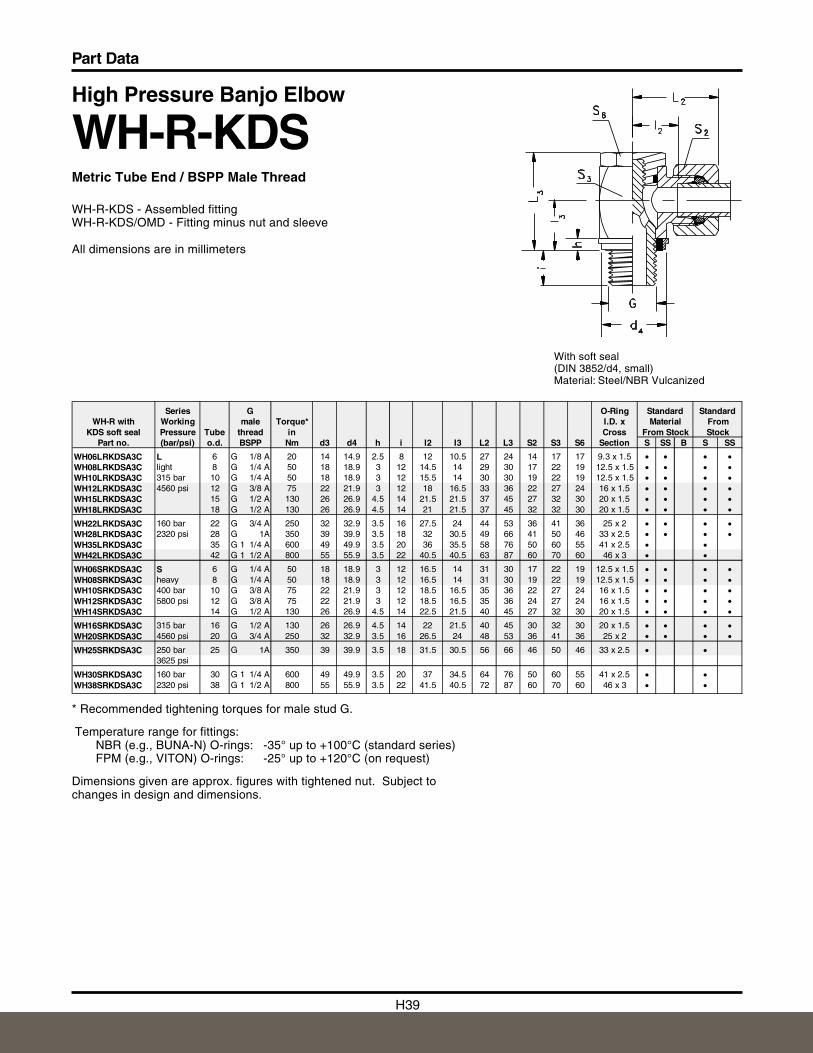
High Pressure Banjo Elbow
WH-R-KDSMetric Tube End / BSPP Male Thread
WH-R-KDS - Assembled fittingWH-R-KDS/OMD - Fitting minus nut and sleeve
All dimensions are in millimeters
With soft seal (DIN 3852/d4, small)Material: Steel/NBR Vulcanized
* Recommended tightening torques for male stud G.
Temperature range for fittings:NBR (e.g., BUNA-N) O-rings: -35° up to +100°C (standard series)FPM (e.g., VITON) O-rings: -25° up to +120°C (on request)
Dimensions given are approx. figures with tightened nut. Subject tochanges in design and dimensions.
Series G O-Ring Standard StandardWH-R with Working male Torque* I.D. x Material From
KDS soft seal Pressure Tube thread in Cross From Stock StockPart no. (bar/psi) o.d. BSPP Nm d3 d4 h i I2 I3 L2 L3 S2 S3 S6 Section S SS B S SS
WH06LRKDSA3C L 6 G 1/8 A 20 14 14.9 2.5 8 12 10.5 27 24 14 17 17 9.3 x 1.5 • • • •WH08LRKDSA3C light 8 G 1/4 A 50 18 18.9 3 12 14.5 14 29 30 17 22 19 12.5 x 1.5 • • • •WH10LRKDSA3C 315 bar 10 G 1/4 A 50 18 18.9 3 12 15.5 14 30 30 19 22 19 12.5 x 1.5 • • • •WH12LRKDSA3C 4560 psi 12 G 3/8 A 75 22 21.9 3 12 18 16.5 33 36 22 27 24 16 x 1.5 • • • •WH15LRKDSA3C 15 G 1/2 A 130 26 26.9 4.5 14 21.5 21.5 37 45 27 32 30 20 x 1.5 • • • •WH18LRKDSA3C 18 G 1/2 A 130 26 26.9 4.5 14 21 21.5 37 45 32 32 30 20 x 1.5 • • • •
WH22LRKDSA3C 160 bar 22 G 3/4 A 250 32 32.9 3.5 16 27.5 24 44 53 36 41 36 25 x 2 • • • •WH28LRKDSA3C 2320 psi 28 G 1A 350 39 39.9 3.5 18 32 30.5 49 66 41 50 46 33 x 2.5 • • • •WH35LRKDSA3C 35 G 1 1/4 A 600 49 49.9 3.5 20 36 35.5 58 76 50 60 55 41 x 2.5 • •WH42LRKDSA3C 42 G 1 1/2 A 800 55 55.9 3.5 22 40.5 40.5 63 87 60 70 60 46 x 3 • •
WH06SRKDSA3C S 6 G 1/4 A 50 18 18.9 3 12 16.5 14 31 30 17 22 19 12.5 x 1.5 • • • •WH08SRKDSA3C heavy 8 G 1/4 A 50 18 18.9 3 12 16.5 14 31 30 19 22 19 12.5 x 1.5 • • • •WH10SRKDSA3C 400 bar 10 G 3/8 A 75 22 21.9 3 12 18.5 16.5 35 36 22 27 24 16 x 1.5 • • • •WH12SRKDSA3C 5800 psi 12 G 3/8 A 75 22 21.9 3 12 18.5 16.5 35 36 24 27 24 16 x 1.5 • • • •WH14SRKDSA3C 14 G 1/2 A 130 26 26.9 4.5 14 22.5 21.5 40 45 27 32 30 20 x 1.5 • • • •
WH16SRKDSA3C 315 bar 16 G 1/2 A 130 26 26.9 4.5 14 22 21.5 40 45 30 32 30 20 x 1.5 • • • •WH20SRKDSA3C 4560 psi 20 G 3/4 A 250 32 32.9 3.5 16 26.5 24 48 53 36 41 36 25 x 2 • • • •
WH25SRKDSA3C 250 bar 25 G 1A 350 39 39.9 3.5 18 31.5 30.5 56 66 46 50 46 33 x 2.5 • •3625 psi
WH30SRKDSA3C 160 bar 30 G 1 1/4 A 600 49 49.9 3.5 20 37 34.5 64 76 50 60 55 41 x 2.5 • •WH38SRKDSA3C 2320 psi 38 G 1 1/2 A 800 55 55.9 3.5 22 41.5 40.5 72 87 60 70 60 46 x 3 • •
H40
Part Data
H
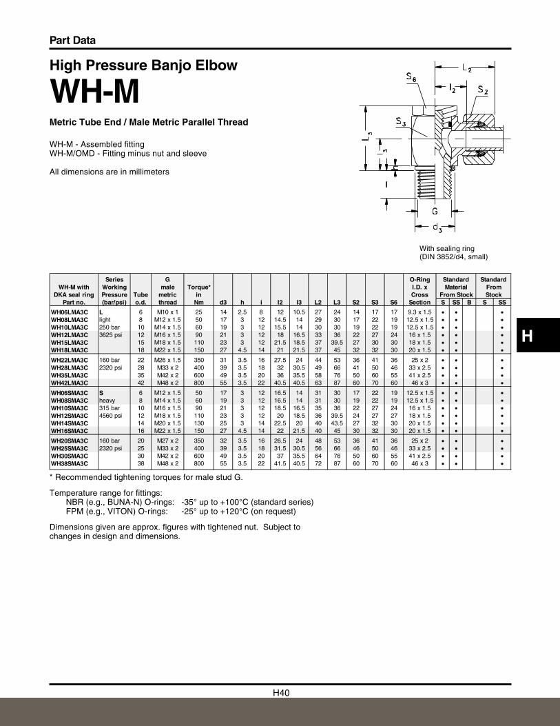
High Pressure Banjo Elbow
WH-MMetric Tube End / Male Metric Parallel Thread
WH-M - Assembled fittingWH-M/OMD - Fitting minus nut and sleeve
All dimensions are in millimeters
With sealing ring (DIN 3852/d4, small)
* Recommended tightening torques for male stud G.
Temperature range for fittings:NBR (e.g., BUNA-N) O-rings: -35° up to +100°C (standard series)FPM (e.g., VITON) O-rings: -25° up to +120°C (on request)
Dimensions given are approx. figures with tightened nut. Subject tochanges in design and dimensions.
Series G O-Ring Standard StandardWH-M with Working male Torque* I.D. x Material From
DKA seal ring Pressure Tube metric in Cross From Stock StockPart no. (bar/psi) o.d. thread Nm d3 h i I2 I3 L2 L3 S2 S3 S6 Section S SS B S SS
WH06LMA3C L 6 M10 x 1 25 14 2.5 8 12 10.5 27 24 14 17 17 9.3 x 1.5 • • •WH08LMA3C light 8 M12 x 1.5 50 17 3 12 14.5 14 29 30 17 22 19 12.5 x 1.5 • • •WH10LMA3C 250 bar 10 M14 x 1.5 60 19 3 12 15.5 14 30 30 19 22 19 12.5 x 1.5 • • •WH12LMA3C 3625 psi 12 M16 x 1.5 90 21 3 12 18 16.5 33 36 22 27 24 16 x 1.5 • • •WH15LMA3C 15 M18 x 1.5 110 23 3 12 21.5 18.5 37 39.5 27 30 30 18 x 1.5 • • •WH18LMA3C 18 M22 x 1.5 150 27 4.5 14 21 21.5 37 45 32 32 30 20 x 1.5 • • •
WH22LMA3C 160 bar 22 M26 x 1.5 350 31 3.5 16 27.5 24 44 53 36 41 36 25 x 2 • • •WH28LMA3C 2320 psi 28 M33 x 2 400 39 3.5 18 32 30.5 49 66 41 50 46 33 x 2.5 • • •WH35LMA3C 35 M42 x 2 600 49 3.5 20 36 35.5 58 76 50 60 55 41 x 2.5 • • •WH42LMA3C 42 M48 x 2 800 55 3.5 22 40.5 40.5 63 87 60 70 60 46 x 3 • • •
WH06SMA3C S 6 M12 x 1.5 50 17 3 12 16.5 14 31 30 17 22 19 12.5 x 1.5 • • •WH08SMA3C heavy 8 M14 x 1.5 60 19 3 12 16.5 14 31 30 19 22 19 12.5 x 1.5 • • •WH10SMA3C 315 bar 10 M16 x 1.5 90 21 3 12 18.5 16.5 35 36 22 27 24 16 x 1.5 • • •WH12SMA3C 4560 psi 12 M18 x 1.5 110 23 3 12 20 18.5 36 39.5 24 27 27 18 x 1.5 • • •WH14SMA3C 14 M20 x 1.5 130 25 3 14 22.5 20 40 43.5 27 32 30 20 x 1.5 • • •WH16SMA3C 16 M22 x 1.5 150 27 4.5 14 22 21.5 40 45 30 32 30 20 x 1.5 • • •
WH20SMA3C 160 bar 20 M27 x 2 350 32 3.5 16 26.5 24 48 53 36 41 36 25 x 2 • • •WH25SMA3C 2320 psi 25 M33 x 2 400 39 3.5 18 31.5 30.5 56 66 46 50 46 33 x 2.5 • • •WH30SMA3C 30 M42 x 2 600 49 3.5 20 37 35.5 64 76 50 60 55 41 x 2.5 • • •WH38SMA3C 38 M48 x 2 800 55 3.5 22 41.5 40.5 72 87 60 70 60 46 x 3 • • •
H41
Part Data
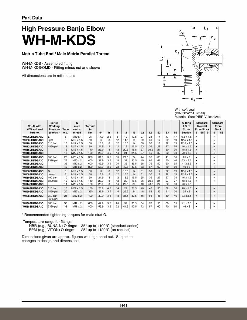
High Pressure Banjo Elbow
WH-M-KDSMetric Tube End / Male Metric Parallel Thread
WH-M-KDS - Assembled fittingWH-M-KDS/OMD - Fitting minus nut and sleeve
All dimensions are in millimeters
With soft seal (DIN 3852/d4, small)Material: Steel/NBR Vulcanized
* Recommended tightening torques for male stud G.
Temperature range for fittings:NBR (e.g., BUNA-N) O-rings: -35° up to +100°C (standard series)FPM (e.g., VITON) O-rings: -25° up to +120°C (on request)
Dimensions given are approx. figures with tightened nut. Subject tochanges in design and dimensions.
Series G O-Ring Standard StandardWH-M with Working male Torque* I.D. x Material From
KDS soft seal Pressure Tube metric in Cross From Stock StockPart no. (bar/psi) o.d. thread Nm d4 h i I2 I3 L2 L3 S2 S3 S6 Section S SS B S SS
WH06LMKDSA3C L 6 M10 x 1 25 14.9 2.5 8 12 10.5 27 24 14 17 17 9.3 x 1.5 • •WH08LMKDSA3C light 8 M12 x 1.5 50 17 3 12 14.5 14 29 30 17 22 19 12.5 x 1.5 • •WH10LMKDSA3C 315 bar 10 M14 x 1.5 60 18.9 3 12 15.5 14 30 30 19 22 19 12.5 x 1.5 • •WH12LMKDSA3C 4560 psi 12 M16 x 1.5 90 21.9 3 12 18 16.5 33 36 22 27 24 16 x 1.5 • •WH15LMKDSA3C 15 M18 x 1.5 110 23.9 3 12 20.5 18.5 37 39.5 27 30 30 18 x 1.5 • •WH18LMKDSA3C 18 M22 x 1.5 150 26.9 4.5 14 21 21.5 37 45 32 32 30 20 x 1.5 • •
WH22LMKDSA3C 160 bar 22 M26 x 1.5 350 31.9 3.5 16 27.5 24 44 53 36 41 36 25 x 2 • •WH28LMKDSA3C 2320 psi 28 M33 x 2 400 39.9 3.5 18 32 30.5 49 66 41 50 46 33 x 2.5 • •WH35LMKDSA3C 35 M42 x 2 600 49.9 3.5 20 36 35.5 58 76 50 60 55 41 x 2.5 • •WH42LMKDSA3C 42 M48 x 2 800 55.9 3.5 22 40.5 40.5 63 87 60 70 60 46 x 3 • •
WH06SMKDSA3C S 6 M12 x 1.5 50 17 3 12 16.5 14 31 30 17 22 19 12.5 x 1.5 • •WH08SMKDSA3C heavy 8 M14 x 1.5 60 18.9 3 12 16.5 14 31 30 19 22 19 12.5 x 1.5 • •WH10SMKDSA3C 400 bar 10 M16 x 1.5 90 21.9 3 12 18.5 16.5 35 36 22 27 24 16 x 1.5 • •WH12SMKDSA3C 5800 psi 12 M18 x 1.5 110 23.9 3 12 20 18.5 36 39.5 24 27 27 18 x 1.5 • •WH14SMKDSA3C 14 M20 x 1.5 130 25.9 3 14 22.5 20 40 43.5 27 32 30 20 x 1.5
WH16SMKDSA3C 315 bar 16 M22 x 1.5 150 26.9 4.5 14 22 21.5 40 45 30 32 30 20 x 1.5 • •WH20SMKDSA3C 4560 psi 20 M27 x 2 350 32.9 3.5 16 26.5 24 48 53 36 41 36 25 x 2 • •
WH25SMKDSA3C 250 bar 25 M33 x 2 400 39.9 3.5 18 31.5 30.5 56 66 46 50 46 33 x 2.5 • •3625 psi
WH30SMKDSA3C 160 bar 30 M42 x 2 600 49.9 3.5 20 37 35.5 64 76 50 60 55 41 x 2.5 • •WH38SMKDSA3C 2320 psi 38 M48 x 2 800 55.9 3.5 22 41.5 40.5 72 87 60 70 60 46 x 3 • •
H42
Part Data
H
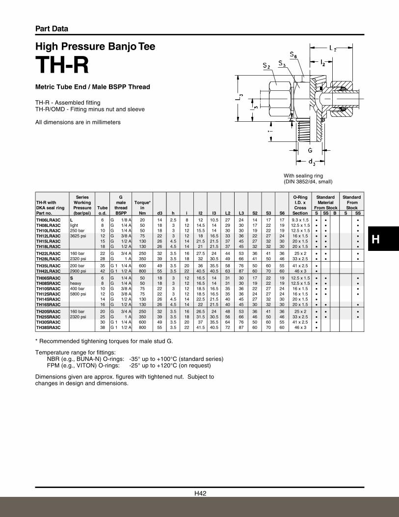
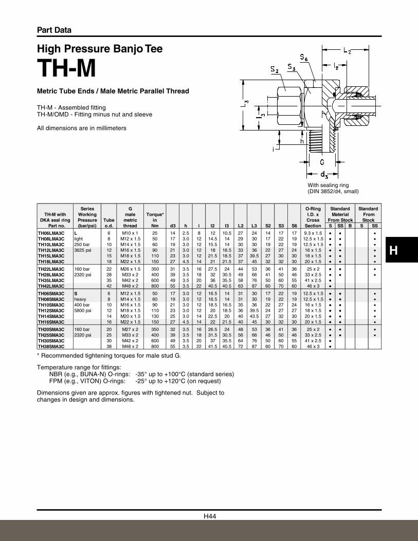
High Pressure Banjo Tee
TH-RMetric Tube End / Male BSPP Thread
TH-R - Assembled fittingTH-R/OMD - Fitting minus nut and sleeve
All dimensions are in millimeters
With sealing ring (DIN 3852/d4, small)
* Recommended tightening torques for male stud G.
Temperature range for fittings:NBR (e.g., BUNA-N) O-rings: -35° up to +100°C (standard series)FPM (e.g., VITON) O-rings: -25° up to +120°C (on request)
Dimensions given are approx. figures with tightened nut. Subject tochanges in design and dimensions.
Series G O-Ring Standard StandardTH-R with Working male Torque* I.D. x Material FromDKA seal ring Pressure Tube thread in Cross From Stock StockPart no. (bar/psi) o.d. BSPP Nm d3 h i I2 I3 L2 L3 S2 S3 S6 Section S SS B S SS
TH06LRA3C L 6 G 1/8 A 20 14 2.5 8 12 10.5 27 24 14 17 17 9.3 x 1.5 • • •TH08LRA3C light 8 G 1/4 A 50 18 3 12 14.5 14 29 30 17 22 19 12.5 x 1.5 • • •TH10LRA3C 250 bar 10 G 1/4 A 50 18 3 12 15.5 14 30 30 19 22 19 12.5 x 1.5 • • •TH12LRA3C 3625 psi 12 G 3/8 A 75 22 3 12 18 16.5 33 36 22 27 24 16 x 1.5 • • •TH15LRA3C 15 G 1/2 A 130 26 4.5 14 21.5 21.5 37 45 27 32 30 20 x 1.5 • • •TH18LRA3C 18 G 1/2 A 130 26 4.5 14 21 21.5 37 45 32 32 30 20 x 1.5 • • •
TH22LRA3C 160 bar 22 G 3/4 A 250 32 3.5 16 27.5 24 44 53 36 41 36 25 x 2 • • •TH28LRA3C 2320 psi 28 G 1 A 350 39 3.5 18 32 30.5 49 66 41 50 46 33 x 2.5 • • •
TH35LRA3C 200 bar 35 G 1 1/4 A 600 49 3.5 20 36 35.5 58 76 50 60 55 41 x 2.5 •TH42LRA3C 2900 psi 42 G 1 1/2 A 800 55 3.5 22 40.5 40.5 63 87 60 70 60 46 x 3 •
TH06SRA3C S 6 G 1/4 A 50 18 3 12 16.5 14 31 30 17 22 19 12.5 x 1.5 • • •TH08SRA3C heavy 8 G 1/4 A 50 18 3 12 16.5 14 31 30 19 22 19 12.5 x 1.5 • • •TH10SRA3C 400 bar 10 G 3/8 A 75 22 3 12 18.5 16.5 35 36 22 27 24 16 x 1.5 • • •TH12SRA3C 5800 psi 12 G 3/8 A 75 22 3 12 18.5 16.5 35 36 24 27 24 16 x 1.5 • • •TH14SRA3C 14 G 1/2 A 130 26 4.5 14 22.5 21.5 40 45 27 32 30 20 x 1.5 •TH16SRA3C 16 G 1/2 A 130 26 4.5 14 22 21.5 40 45 30 32 30 20 x 1.5 • • •
TH20SRA3C 160 bar 20 G 3/4 A 250 32 3.5 16 26.5 24 48 53 36 41 36 25 x 2 • • •TH25SRA3C 2320 psi 25 G 1 A 350 39 3.5 18 31.5 30.5 56 66 46 50 46 33 x 2.5 • • •TH30SRA3C 30 G 1 1/4 A 600 49 3.5 20 37 35.5 64 76 50 60 55 41 x 2.5 •TH38SRA3C 38 G 1 1/2 A 800 55 3.5 22 41.5 40.5 72 87 60 70 60 46 x 3 •
H43
Part Data
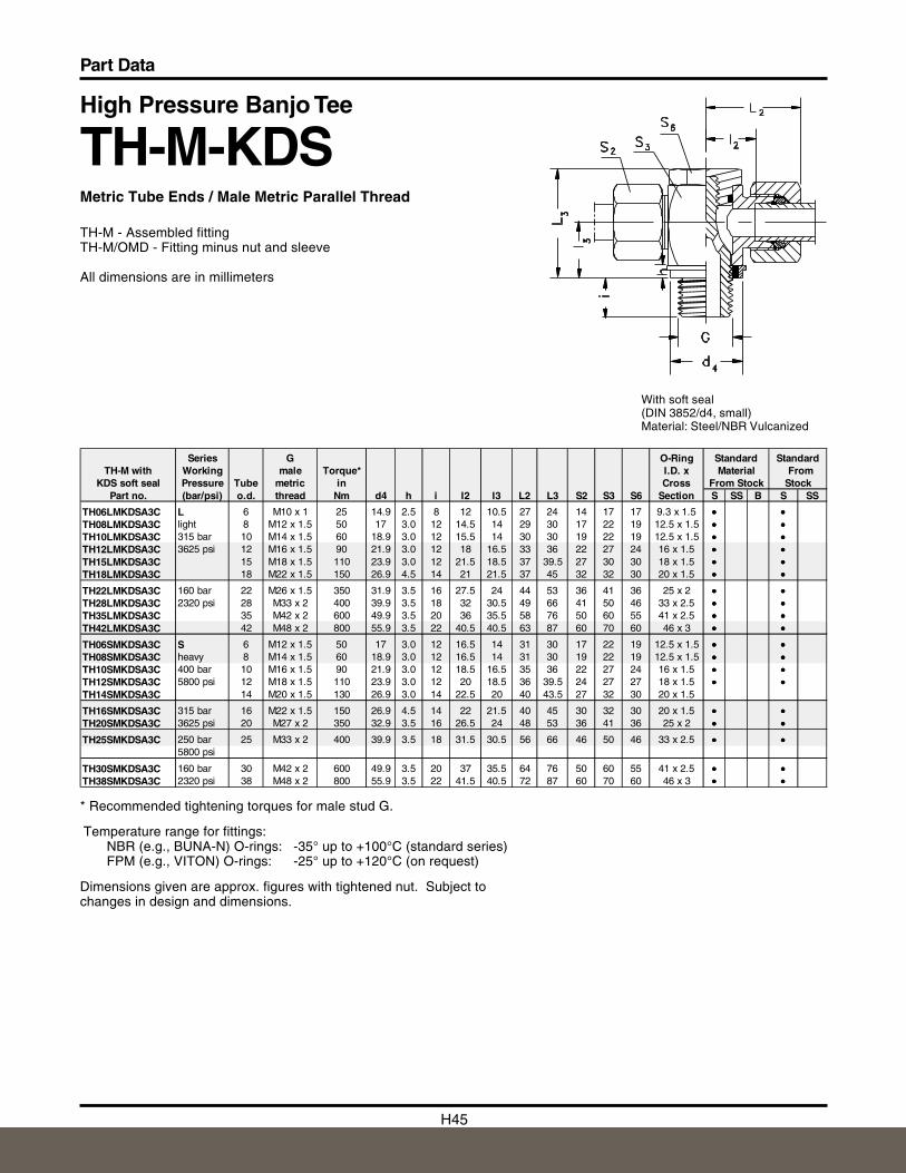
With soft seal (DIN 3852/d4, small)Material: Steel/NBR Vulcanized
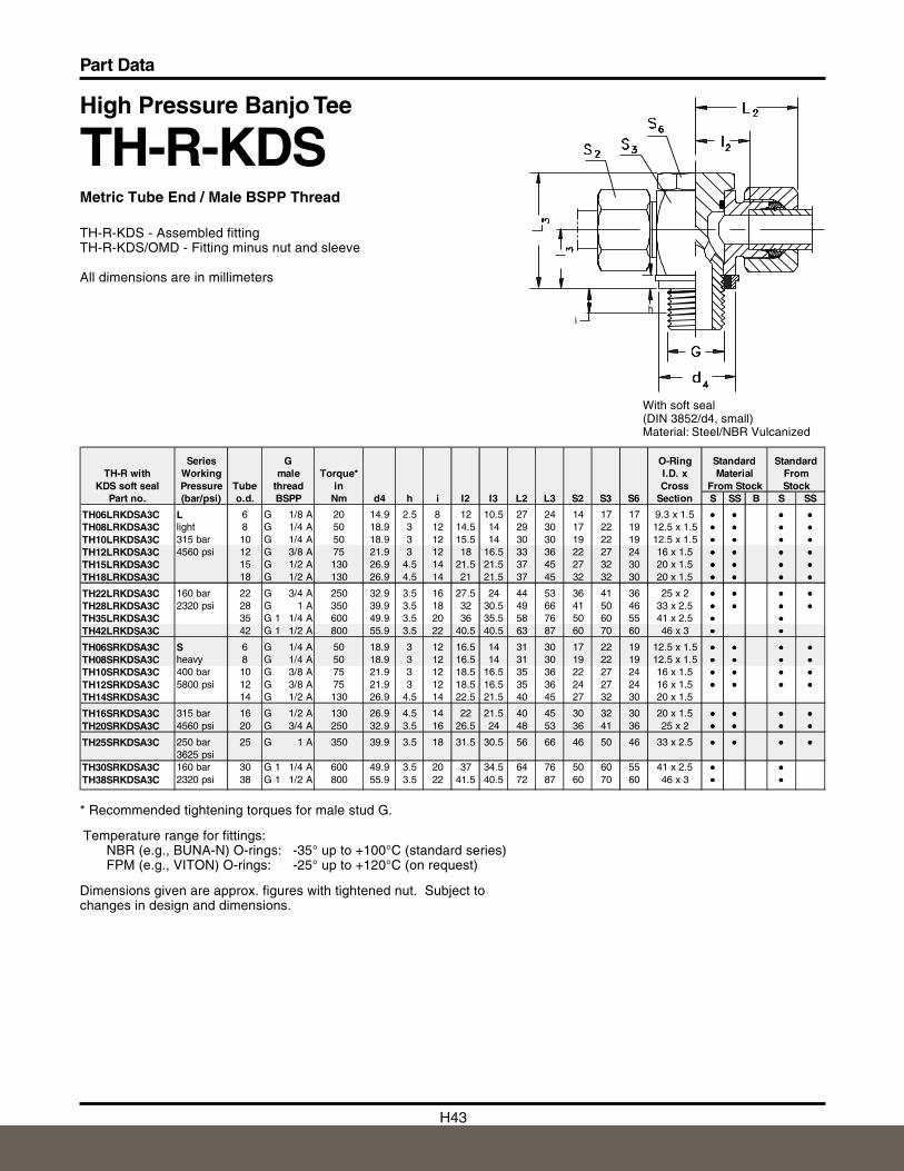
High Pressure Banjo Tee
TH-R-KDSMetric Tube End / Male BSPP Thread
TH-R-KDS - Assembled fittingTH-R-KDS/OMD - Fitting minus nut and sleeve
All dimensions are in millimeters
* Recommended tightening torques for male stud G.
Temperature range for fittings:NBR (e.g., BUNA-N) O-rings: -35° up to +100°C (standard series)FPM (e.g., VITON) O-rings: -25° up to +120°C (on request)
Dimensions given are approx. figures with tightened nut. Subject tochanges in design and dimensions.
hi
Series G O-Ring Standard StandardTH-R with Working male Torque* I.D. x Material From
KDS soft seal Pressure Tube thread in Cross From Stock StockPart no. (bar/psi) o.d. BSPP Nm d4 h i I2 I3 L2 L3 S2 S3 S6 Section S SS B S SS
TH06LRKDSA3C L 6 G 1/8 A 20 14.9 2.5 8 12 10.5 27 24 14 17 17 9.3 x 1.5 ••• ••• ••• •••TH08LRKDSA3C light 8 G 1/4 A 50 18.9 3 12 14.5 14 29 30 17 22 19 12.5 x 1.5 ••• ••• ••• •••TH10LRKDSA3C 315 bar 10 G 1/4 A 50 18.9 3 12 15.5 14 30 30 19 22 19 12.5 x 1.5 ••• ••• ••• •••TH12LRKDSA3C 4560 psi 12 G 3/8 A 75 21.9 3 12 18 16.5 33 36 22 27 24 16 x 1.5 ••• ••• ••• •••TH15LRKDSA3C 15 G 1/2 A 130 26.9 4.5 14 21.5 21.5 37 45 27 32 30 20 x 1.5 ••• ••• ••• •••TH18LRKDSA3C 18 G 1/2 A 130 26.9 4.5 14 21 21.5 37 45 32 32 30 20 x 1.5 ••• ••• ••• •••
TH22LRKDSA3C 160 bar 22 G 3/4 A 250 32.9 3.5 16 27.5 24 44 53 36 41 36 25 x 2 ••• ••• ••• •••TH28LRKDSA3C 2320 psi 28 G 1 A 350 39.9 3.5 18 32 30.5 49 66 41 50 46 33 x 2.5 ••• ••• ••• •••TH35LRKDSA3C 35 G 1 1/4 A 600 49.9 3.5 20 36 35.5 58 76 50 60 55 41 x 2.5 ••• •••TH42LRKDSA3C 42 G 1 1/2 A 800 55.9 3.5 22 40.5 40.5 63 87 60 70 60 46 x 3 ••• •••
TH06SRKDSA3C S 6 G 1/4 A 50 18.9 3 12 16.5 14 31 30 17 22 19 12.5 x 1.5 ••• ••• ••• •••TH08SRKDSA3C heavy 8 G 1/4 A 50 18.9 3 12 16.5 14 31 30 19 22 19 12.5 x 1.5 ••• ••• ••• •••TH10SRKDSA3C 400 bar 10 G 3/8 A 75 21.9 3 12 18.5 16.5 35 36 22 27 24 16 x 1.5 ••• ••• ••• •••TH12SRKDSA3C 5800 psi 12 G 3/8 A 75 21.9 3 12 18.5 16.5 35 36 24 27 24 16 x 1.5 ••• ••• ••• •••TH14SRKDSA3C 14 G 1/2 A 130 26.9 4.5 14 22.5 21.5 40 45 27 32 30 20 x 1.5
TH16SRKDSA3C 315 bar 16 G 1/2 A 130 26.9 4.5 14 22 21.5 40 45 30 32 30 20 x 1.5 ••• ••• ••• •••TH20SRKDSA3C 4560 psi 20 G 3/4 A 250 32.9 3.5 16 26.5 24 48 53 36 41 36 25 x 2 ••• ••• ••• •••
TH25SRKDSA3C 250 bar 25 G 1 A 350 39.9 3.5 18 31.5 30.5 56 66 46 50 46 33 x 2.5 ••• ••• ••• •••3625 psi
TH30SRKDSA3C 160 bar 30 G 1 1/4 A 600 49.9 3.5 20 37 34.5 64 76 50 60 55 41 x 2.5 ••• •••TH38SRKDSA3C 2320 psi 38 G 1 1/2 A 800 55.9 3.5 22 41.5 40.5 72 87 60 70 60 46 x 3 ••• •••
H44
Part Data
H
High Pressure Banjo Tee
TH-MMetric Tube Ends / Male Metric Parallel Thread
TH-M - Assembled fittingTH-M/OMD - Fitting minus nut and sleeve
All dimensions are in millimeters
With sealing ring (DIN 3852/d4, small)
* Recommended tightening torques for male stud G.
Temperature range for fittings:NBR (e.g., BUNA-N) O-rings: -35° up to +100°C (standard series)FPM (e.g., VITON) O-rings: -25° up to +120°C (on request)
Dimensions given are approx. figures with tightened nut. Subject tochanges in design and dimensions.
hi
Series G O-Ring Standard StandardTH-M with Working male Torque* I.D. x Material From
DKA seal ring Pressure Tube metric in Cross From Stock Stock Part no. (bar/psi) o.d. thread Nm d3 h i I2 I3 L2 L3 S2 S3 S6 Section S SS B S SS
TH06LMA3C L 6 M10 x 1 25 14 2.5 8 12 10.5 27 24 14 17 17 9.3 x 1.5 ••• ••• •TH08LMA3C light 8 M12 x 1.5 50 17 3.0 12 14.5 14 29 30 17 22 19 12.5 x 1.5 ••• ••• •TH10LMA3C 250 bar 10 M14 x 1.5 60 19 3.0 12 15.5 14 30 30 19 22 19 12.5 x 1.5 ••• ••• •TH12LMA3C 3625 psi 12 M16 x 1.5 90 21 3.0 12 18 16.5 33 36 22 27 24 16 x 1.5 ••• ••• •TH15LMA3C 15 M18 x 1.5 110 23 3.0 12 21.5 18.5 37 39.5 27 30 30 18 x 1.5 ••• ••• •TH18LMA3C 18 M22 x 1.5 150 27 4.5 14 21 21.5 37 45 32 32 30 20 x 1.5 ••• ••• •
TH22LMA3C 160 bar 22 M26 x 1.5 350 31 3.5 16 27.5 24 44 53 36 41 36 25 x 2 ••• ••• •TH28LMA3C 2320 psi 28 M33 x 2 400 39 3.5 18 32 30.5 49 66 41 50 46 33 x 2.5 ••• ••• •TH35LMA3C 35 M42 x 2 600 49 3.5 20 36 35.5 58 76 50 60 55 41 x 2.5 •••TH42LMA3C 42 M48 x 2 800 55 3.5 22 40.5 40.5 63 87 60 70 60 46 x 3 •••
TH06SMA3C S 6 M12 x 1.5 50 17 3.0 12 16.5 14 31 30 17 22 19 12.5 x 1.5 ••• ••• •TH08SMA3C heavy 8 M14 x 1.5 60 19 3.0 12 16.5 14 31 30 19 22 19 12.5 x 1.5 ••• ••• •TH10SMA3C 400 bar 10 M16 x 1.5 90 21 3.0 12 18.5 16.5 35 36 22 27 24 16 x 1.5 ••• ••• •TH12SMA3C 5800 psi 12 M18 x 1.5 110 23 3.0 12 20 18.5 36 39.5 24 27 27 18 x 1.5 ••• ••• •TH14SMA3C 14 M20 x 1.5 130 25 3.0 14 22.5 20 40 43.5 27 32 30 20 x 1.5 ••• ••• •TH16SMA3C 16 M22 x 1.5 150 27 4.5 14 22 21.5 40 45 30 32 30 20 x 1.5 ••• ••• •
TH20SMA3C 160 bar 20 M27 x 2 350 32 3.5 16 26.5 24 48 53 36 41 36 25 x 2 ••• ••• •TH25SMA3C 2320 psi 25 M33 x 2 400 39 3.5 18 31.5 30.5 56 66 46 50 46 33 x 2.5 ••• ••• •TH30SMA3C 30 M42 x 2 600 49 3.5 20 37 35.5 64 76 50 60 55 41 x 2.5 •••TH38SMA3C 38 M48 x 2 800 55 3.5 22 41.5 40.5 72 87 60 70 60 46 x 3 •••
H45
Part Data
High Pressure Banjo Tee
TH-M-KDSMetric Tube Ends / Male Metric Parallel Thread
TH-M - Assembled fittingTH-M/OMD - Fitting minus nut and sleeve
All dimensions are in millimeters
With soft seal (DIN 3852/d4, small)Material: Steel/NBR Vulcanized
* Recommended tightening torques for male stud G.
Temperature range for fittings:NBR (e.g., BUNA-N) O-rings: -35° up to +100°C (standard series)FPM (e.g., VITON) O-rings: -25° up to +120°C (on request)
Dimensions given are approx. figures with tightened nut. Subject tochanges in design and dimensions.
Series G O-Ring Standard StandardTH-M with Working male Torque* I.D. x Material From
KDS soft seal Pressure Tube metric in Cross From Stock StockPart no. (bar/psi) o.d. thread Nm d4 h i I2 I3 L2 L3 S2 S3 S6 Section S SS B S SS
TH06LMKDSA3C L 6 M10 x 1 25 14.9 2.5 8 12 10.5 27 24 14 17 17 9.3 x 1.5 ••• •••TH08LMKDSA3C light 8 M12 x 1.5 50 17 3.0 12 14.5 14 29 30 17 22 19 12.5 x 1.5 ••• •••TH10LMKDSA3C 315 bar 10 M14 x 1.5 60 18.9 3.0 12 15.5 14 30 30 19 22 19 12.5 x 1.5 ••• •••TH12LMKDSA3C 3625 psi 12 M16 x 1.5 90 21.9 3.0 12 18 16.5 33 36 22 27 24 16 x 1.5 ••• •••TH15LMKDSA3C 15 M18 x 1.5 110 23.9 3.0 12 21.5 18.5 37 39.5 27 30 30 18 x 1.5 ••• •••TH18LMKDSA3C 18 M22 x 1.5 150 26.9 4.5 14 21 21.5 37 45 32 32 30 20 x 1.5 ••• •••
TH22LMKDSA3C 160 bar 22 M26 x 1.5 350 31.9 3.5 16 27.5 24 44 53 36 41 36 25 x 2 ••• •••TH28LMKDSA3C 2320 psi 28 M33 x 2 400 39.9 3.5 18 32 30.5 49 66 41 50 46 33 x 2.5 ••• •••TH35LMKDSA3C 35 M42 x 2 600 49.9 3.5 20 36 35.5 58 76 50 60 55 41 x 2.5 ••• •••TH42LMKDSA3C 42 M48 x 2 800 55.9 3.5 22 40.5 40.5 63 87 60 70 60 46 x 3 ••• •••
TH06SMKDSA3C S 6 M12 x 1.5 50 17 3.0 12 16.5 14 31 30 17 22 19 12.5 x 1.5 ••• •••TH08SMKDSA3C heavy 8 M14 x 1.5 60 18.9 3.0 12 16.5 14 31 30 19 22 19 12.5 x 1.5 ••• •••TH10SMKDSA3C 400 bar 10 M16 x 1.5 90 21.9 3.0 12 18.5 16.5 35 36 22 27 24 16 x 1.5 ••• •••TH12SMKDSA3C 5800 psi 12 M18 x 1.5 110 23.9 3.0 12 20 18.5 36 39.5 24 27 27 18 x 1.5 ••• •••TH14SMKDSA3C 14 M20 x 1.5 130 26.9 3.0 14 22.5 20 40 43.5 27 32 30 20 x 1.5
TH16SMKDSA3C 315 bar 16 M22 x 1.5 150 26.9 4.5 14 22 21.5 40 45 30 32 30 20 x 1.5 ••• •••TH20SMKDSA3C 3625 psi 20 M27 x 2 350 32.9 3.5 16 26.5 24 48 53 36 41 36 25 x 2 ••• •••
TH25SMKDSA3C 250 bar 25 M33 x 2 400 39.9 3.5 18 31.5 30.5 56 66 46 50 46 33 x 2.5 ••• •••5800 psi
TH30SMKDSA3C 160 bar 30 M42 x 2 600 49.9 3.5 20 37 35.5 64 76 50 60 55 41 x 2.5 ••• •••TH38SMKDSA3C 2320 psi 38 M48 x 2 800 55.9 3.5 22 41.5 40.5 72 87 60 70 60 46 x 3 ••• •••
H46
Part Data
H
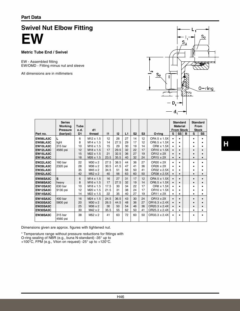
Swivel Nut Elbow Fitting
EWMetric Tube End / Swivel
EW - Assembled fittingEW/OMD - Fitting minus nut and sleeve
All dimensions are in millimeters
Dimensions given are approx. figures with tightened nut.
* Temperature range without pressure reductions for fittings withO-ring sealing of NBR (e.g., buna N-standard) -35° up to+100°C, FPM (e.g., Viton on request) -25° up to +120°C.
Series Standard StandardWorking Tube Material FromPressure o.d. d1 From Stock Stock
Part no. (bar/psi) D1 thread I1 I2 L1 S2 S3 O-ring S SS B S SS
EW06LA3C L 6 M12 x 1.5 12 26 27 14 12 OR4.5 x 1.5X • • • •EW08LA3C light 8 M14 x 1.5 14 27.5 29 17 12 OR6.5 x 1.5X • • • •EW10LA3C 315 bar 10 M16 x 1.5 15 29 30 19 14 OR8 x 1.5X • • • •EW12LA3C 4560 psi 12 M18 x 1.5 17 29.5 32 22 17 OR10 x 1.5X • • • •EW15LA3C 15 M22 x 1.5 21 32.5 36 27 19 OR12 x 2X • • • •EW18LA3C 18 M26 x 1.5 23.5 35.5 40 32 24 OR15 x 2X • • • •
EW22LA3C 160 bar 22 M30 x 2 27.5 38.5 44 36 27 OR20 x 2X • • • •EW28LA3C 2320 psi 28 M36 x 2 30.5 41.5 47 41 36 OR26 x 2X • • • •EW35LA3C 35 M45 x 2 34.5 51 56 50 41 OR32 x 2.5X • • • •EW42LA3C 42 M52 x 2 40 56 63 60 50 OR38 x 2.5X • • • •
EW06SA3C S 6 M14 x 1.5 16 27 31 17 12 OR4.5 x 1.5X • • • •EW08SA3C heavy 8 M16 x 1.5 17 27.5 32 19 14 OR6.5 x 1.5X • • • •EW10SA3C 630 bar 10 M18 x 1.5 17.5 30 34 22 17 OR8 x 1.5X • • • •EW12SA3C 9130 psi 12 M20 x 1.5 21.5 31 38 24 17 OR10 x 1.5X • • • •EW14SA3C 14 M22 x 1.5 22 35 40 27 19 OR11 x 2X • • • •
EW16SA3C 400 bar 16 M24 x 1.5 24.5 36.5 43 30 24 OR13 x 2X • • • •EW20SA3C 5800 psi 20 M30 x 2 26.5 44.5 48 36 27 OR16.3 x 2.4X • • • •EW25SA3C 25 M36 x 2 30 50 54 46 36 OR20.3 x 2.4X • • • •EW30SA3C 30 M42 x 2 35.5 55 62 50 41 OR25.3 x 2.4X • • • •
EW38SA3C 315 bar 38 M52 x 2 41 63 72 60 50 OR33.3 x 2.4X • • • •4560 psi
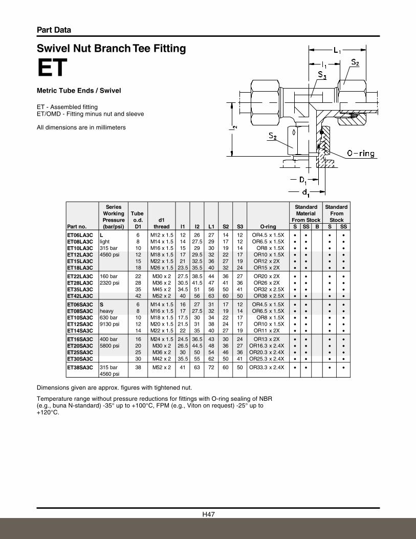
H47
Part Data
Dimensions given are approx. figures with tightened nut.
Temperature range without pressure reductions for fittings with O-ring sealing of NBR(e.g., buna N-standard) -35° up to +100°C, FPM (e.g., Viton on request) -25° up to+120°C.
Swivel Nut Branch Tee Fitting
ETMetric Tube Ends / Swivel
ET - Assembled fittingET/OMD - Fitting minus nut and sleeve
All dimensions are in millimeters
Series Standard StandardWorking Tube Material FromPressure o.d. d1 From Stock Stock
Part no. (bar/psi) D1 thread I1 I2 L1 S2 S3 O-ring S SS B S SS
ET06LA3C L 6 M12 x 1.5 12 26 27 14 12 OR4.5 x 1.5X • • • •ET08LA3C light 8 M14 x 1.5 14 27.5 29 17 12 OR6.5 x 1.5X • • • •ET10LA3C 315 bar 10 M16 x 1.5 15 29 30 19 14 OR8 x 1.5X • • • •ET12LA3C 4560 psi 12 M18 x 1.5 17 29.5 32 22 17 OR10 x 1.5X • • • •ET15LA3C 15 M22 x 1.5 21 32.5 36 27 19 OR12 x 2X • • • •ET18LA3C 18 M26 x 1.5 23.5 35.5 40 32 24 OR15 x 2X • • • •
ET22LA3C 160 bar 22 M30 x 2 27.5 38.5 44 36 27 OR20 x 2X • • • •ET28LA3C 2320 psi 28 M36 x 2 30.5 41.5 47 41 36 OR26 x 2X • • • •ET35LA3C 35 M45 x 2 34.5 51 56 50 41 OR32 x 2.5X • • • •ET42LA3C 42 M52 x 2 40 56 63 60 50 OR38 x 2.5X • • • •
ET06SA3C S 6 M14 x 1.5 16 27 31 17 12 OR4.5 x 1.5X • • • •ET08SA3C heavy 8 M16 x 1.5 17 27.5 32 19 14 OR6.5 x 1.5X • • • •ET10SA3C 630 bar 10 M18 x 1.5 17.5 30 34 22 17 OR8 x 1.5X • • • •ET12SA3C 9130 psi 12 M20 x 1.5 21.5 31 38 24 17 OR10 x 1.5X • • • •ET14SA3C 14 M22 x 1.5 22 35 40 27 19 OR11 x 2X • • • •
ET16SA3C 400 bar 16 M24 x 1.5 24.5 36.5 43 30 24 OR13 x 2X • • • •ET20SA3C 5800 psi 20 M30 x 2 26.5 44.5 48 36 27 OR16.3 x 2.4X • • • •ET25SA3C 25 M36 x 2 30 50 54 46 36 OR20.3 x 2.4X • • • •ET30SA3C 30 M42 x 2 35.5 55 62 50 41 OR25.3 x 2.4X • • • •
ET38SA3C 315 bar 38 M52 x 2 41 63 72 60 50 OR33.3 x 2.4X • • • •4560 psi
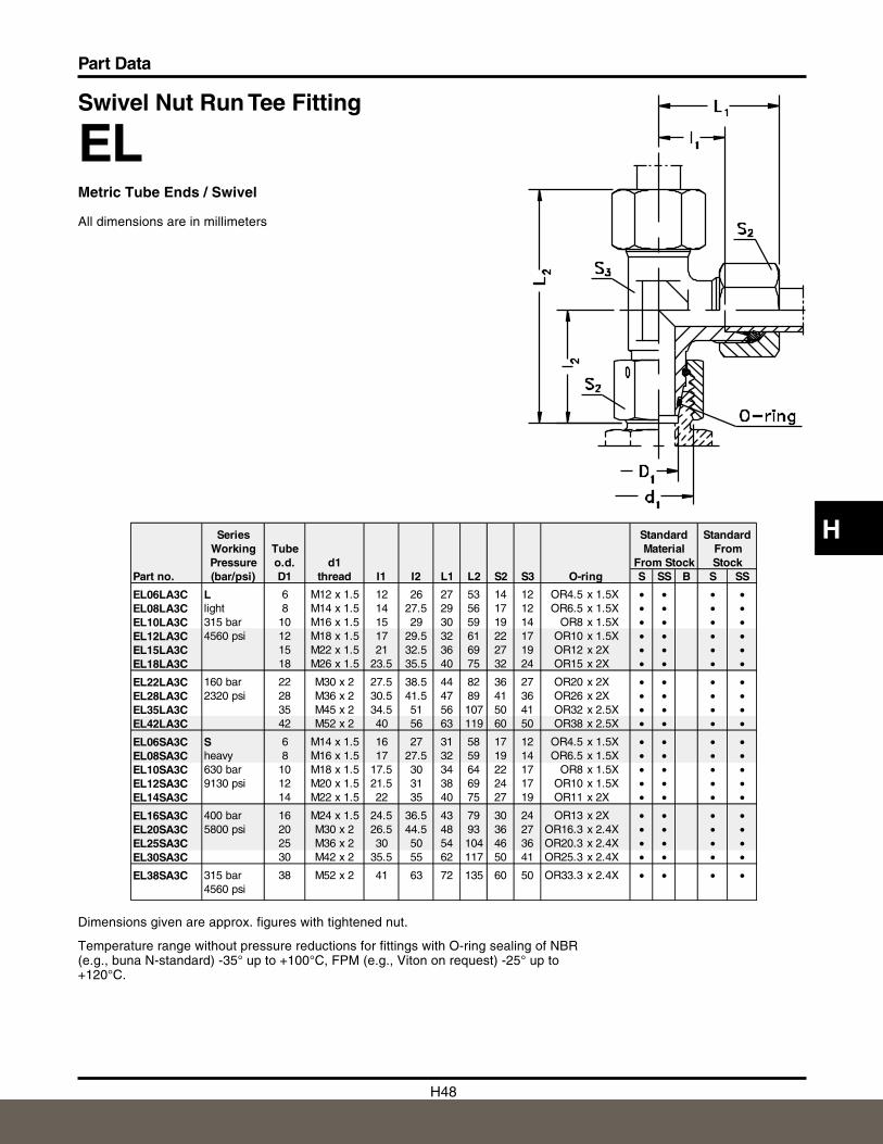
H48
Part Data
H
Swivel Nut Run Tee Fitting
ELMetric Tube Ends / Swivel
All dimensions are in millimeters
Dimensions given are approx. figures with tightened nut.
Temperature range without pressure reductions for fittings with O-ring sealing of NBR(e.g., buna N-standard) -35° up to +100°C, FPM (e.g., Viton on request) -25° up to+120°C.
Series Standard StandardWorking Tube Material FromPressure o.d. d1 From Stock Stock
Part no. (bar/psi) D1 thread I1 I2 L1 L2 S2 S3 O-ring S SS B S SS
EL06LA3C L 6 M12 x 1.5 12 26 27 53 14 12 OR4.5 x 1.5X • • • •EL08LA3C light 8 M14 x 1.5 14 27.5 29 56 17 12 OR6.5 x 1.5X • • • •EL10LA3C 315 bar 10 M16 x 1.5 15 29 30 59 19 14 OR8 x 1.5X • • • •EL12LA3C 4560 psi 12 M18 x 1.5 17 29.5 32 61 22 17 OR10 x 1.5X • • • •EL15LA3C 15 M22 x 1.5 21 32.5 36 69 27 19 OR12 x 2X • • • •EL18LA3C 18 M26 x 1.5 23.5 35.5 40 75 32 24 OR15 x 2X • • • •
EL22LA3C 160 bar 22 M30 x 2 27.5 38.5 44 82 36 27 OR20 x 2X • • • •EL28LA3C 2320 psi 28 M36 x 2 30.5 41.5 47 89 41 36 OR26 x 2X • • • •EL35LA3C 35 M45 x 2 34.5 51 56 107 50 41 OR32 x 2.5X • • • •EL42LA3C 42 M52 x 2 40 56 63 119 60 50 OR38 x 2.5X • • • •
EL06SA3C S 6 M14 x 1.5 16 27 31 58 17 12 OR4.5 x 1.5X • • • •EL08SA3C heavy 8 M16 x 1.5 17 27.5 32 59 19 14 OR6.5 x 1.5X • • • •EL10SA3C 630 bar 10 M18 x 1.5 17.5 30 34 64 22 17 OR8 x 1.5X • • • •EL12SA3C 9130 psi 12 M20 x 1.5 21.5 31 38 69 24 17 OR10 x 1.5X • • • •EL14SA3C 14 M22 x 1.5 22 35 40 75 27 19 OR11 x 2X • • • •
EL16SA3C 400 bar 16 M24 x 1.5 24.5 36.5 43 79 30 24 OR13 x 2X • • • •EL20SA3C 5800 psi 20 M30 x 2 26.5 44.5 48 93 36 27 OR16.3 x 2.4X • • • •EL25SA3C 25 M36 x 2 30 50 54 104 46 36 OR20.3 x 2.4X • • • •EL30SA3C 30 M42 x 2 35.5 55 62 117 50 41 OR25.3 x 2.4X • • • •
EL38SA3C 315 bar 38 M52 x 2 41 63 72 135 60 50 OR33.3 x 2.4X • • • •4560 psi
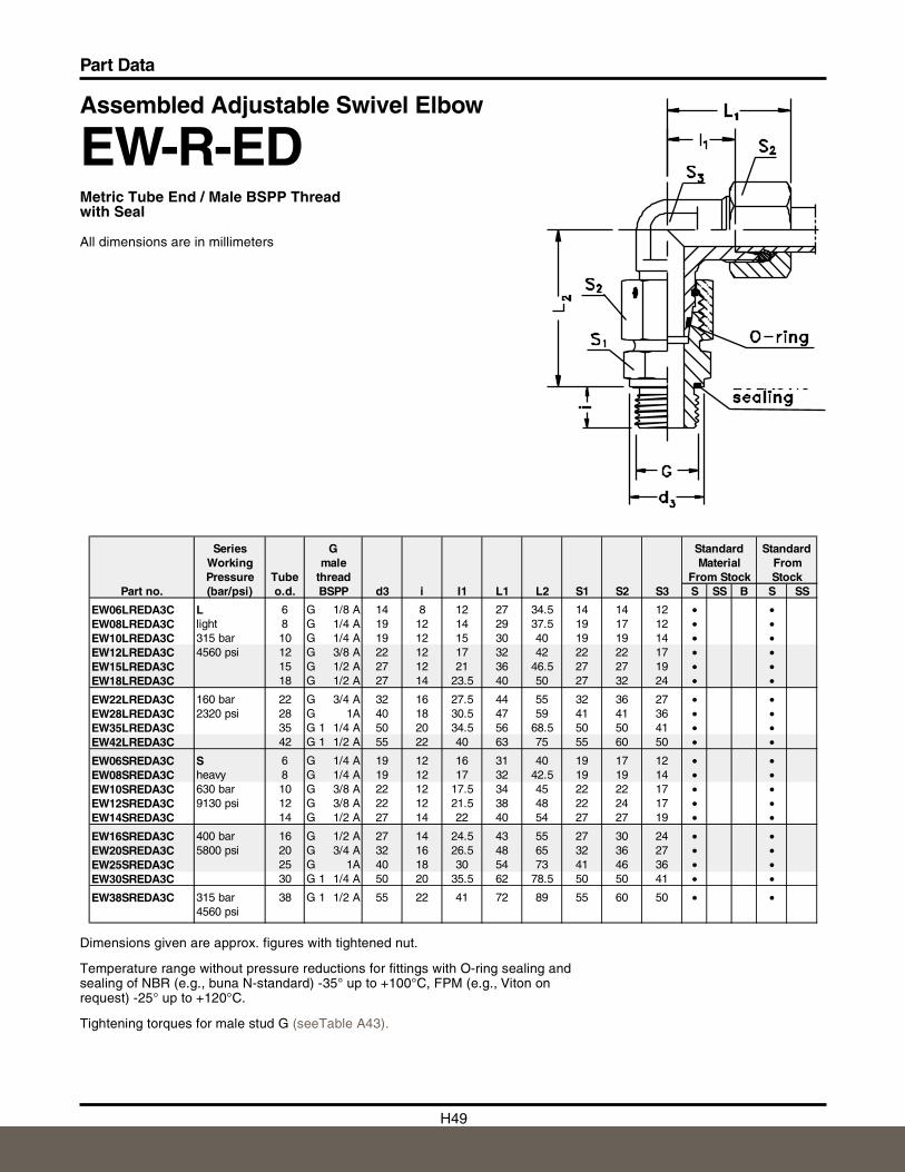
H49
Part Data
Assembled Adjustable Swivel Elbow
EW-R-EDMetric Tube End / Male BSPP Threadwith Seal
All dimensions are in millimeters
Dimensions given are approx. figures with tightened nut.
Temperature range without pressure reductions for fittings with O-ring sealing andsealing of NBR (e.g., buna N-standard) -35° up to +100°C, FPM (e.g., Viton onrequest) -25° up to +120°C.
Tightening torques for male stud G (seeTable A43).
Series G Standard StandardWorking male Material FromPressure Tube thread From Stock Stock
Part no. (bar/psi) o.d. BSPP d3 i I1 L1 L2 S1 S2 S3 S SS B S SS
EW06LREDA3C L 6 G 1/8 A 14 8 12 27 34.5 14 14 12 • •EW08LREDA3C light 8 G 1/4 A 19 12 14 29 37.5 19 17 12 • •EW10LREDA3C 315 bar 10 G 1/4 A 19 12 15 30 40 19 19 14 • •EW12LREDA3C 4560 psi 12 G 3/8 A 22 12 17 32 42 22 22 17 • •EW15LREDA3C 15 G 1/2 A 27 12 21 36 46.5 27 27 19 • •EW18LREDA3C 18 G 1/2 A 27 14 23.5 40 50 27 32 24 • •
EW22LREDA3C 160 bar 22 G 3/4 A 32 16 27.5 44 55 32 36 27 • •EW28LREDA3C 2320 psi 28 G 1A 40 18 30.5 47 59 41 41 36 • •EW35LREDA3C 35 G 1 1/4 A 50 20 34.5 56 68.5 50 50 41 • •EW42LREDA3C 42 G 1 1/2 A 55 22 40 63 75 55 60 50 • •
EW06SREDA3C S 6 G 1/4 A 19 12 16 31 40 19 17 12 • •EW08SREDA3C heavy 8 G 1/4 A 19 12 17 32 42.5 19 19 14 • •EW10SREDA3C 630 bar 10 G 3/8 A 22 12 17.5 34 45 22 22 17 • •EW12SREDA3C 9130 psi 12 G 3/8 A 22 12 21.5 38 48 22 24 17 • •EW14SREDA3C 14 G 1/2 A 27 14 22 40 54 27 27 19 • •
EW16SREDA3C 400 bar 16 G 1/2 A 27 14 24.5 43 55 27 30 24 • •EW20SREDA3C 5800 psi 20 G 3/4 A 32 16 26.5 48 65 32 36 27 • •EW25SREDA3C 25 G 1A 40 18 30 54 73 41 46 36 • •EW30SREDA3C 30 G 1 1/4 A 50 20 35.5 62 78.5 50 50 41 • •
EW38SREDA3C 315 bar 38 G 1 1/2 A 55 22 41 72 89 55 60 50 • •4560 psi
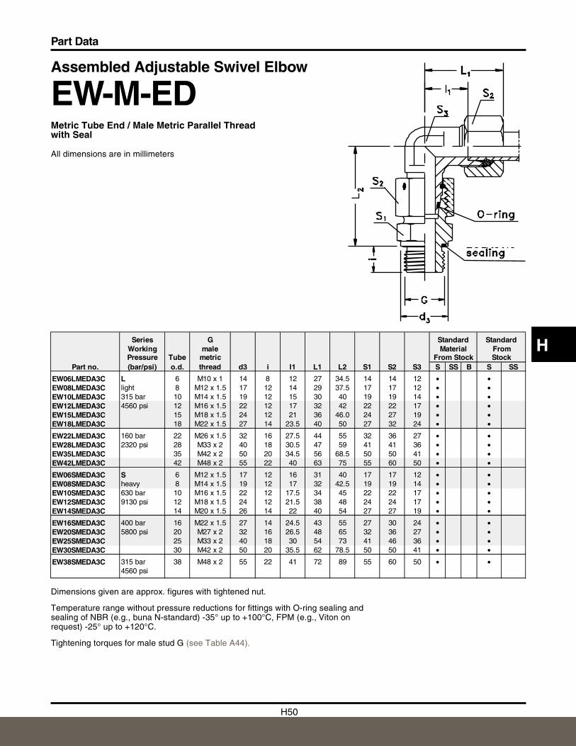
H50
Part Data
H
Assembled Adjustable Swivel Elbow
EW-M-EDMetric Tube End / Male Metric Parallel Threadwith Seal
All dimensions are in millimeters
Dimensions given are approx. figures with tightened nut.
Temperature range without pressure reductions for fittings with O-ring sealing andsealing of NBR (e.g., buna N-standard) -35° up to +100°C, FPM (e.g., Viton onrequest) -25° up to +120°C.
Tightening torques for male stud G (see Table A44).
Series G Standard StandardWorking male Material FromPressure Tube metric From Stock
Part no. (bar/psi) o.d. thread d3 i I1 L1 L2 S1 S2 S3 S SS B S SS
EW06LMEDA3C L 6 M10 x 1 14 8 12 27 34.5 14 14 12 • •EW08LMEDA3C light 8 M12 x 1.5 17 12 14 29 37.5 17 17 12 • •EW10LMEDA3C 315 bar 10 M14 x 1.5 19 12 15 30 40 19 19 14 • •EW12LMEDA3C 4560 psi 12 M16 x 1.5 22 12 17 32 42 22 22 17 • •EW15LMEDA3C 15 M18 x 1.5 24 12 21 36 46.0 24 27 19 • •EW18LMEDA3C 18 M22 x 1.5 27 14 23.5 40 50 27 32 24 • •
EW22LMEDA3C 160 bar 22 M26 x 1.5 32 16 27.5 44 55 32 36 27 • •EW28LMEDA3C 2320 psi 28 M33 x 2 40 18 30.5 47 59 41 41 36 • •EW35LMEDA3C 35 M42 x 2 50 20 34.5 56 68.5 50 50 41 • •EW42LMEDA3C 42 M48 x 2 55 22 40 63 75 55 60 50 • •
EW06SMEDA3C S 6 M12 x 1.5 17 12 16 31 40 17 17 12 • •EW08SMEDA3C heavy 8 M14 x 1.5 19 12 17 32 42.5 19 19 14 • •EW10SMEDA3C 630 bar 10 M16 x 1.5 22 12 17.5 34 45 22 22 17 • •EW12SMEDA3C 9130 psi 12 M18 x 1.5 24 12 21.5 38 48 24 24 17 • •EW14SMEDA3C 14 M20 x 1.5 26 14 22 40 54 27 27 19 • •
EW16SMEDA3C 400 bar 16 M22 x 1.5 27 14 24.5 43 55 27 30 24 • •EW20SMEDA3C 5800 psi 20 M27 x 2 32 16 26.5 48 65 32 36 27 • •EW25SMEDA3C 25 M33 x 2 40 18 30 54 73 41 46 36 • •EW30SMEDA3C 30 M42 x 2 50 20 35.5 62 78.5 50 50 41 • •
EW38SMEDA3C 315 bar 38 M48 x 2 55 22 41 72 89 55 60 50 • •4560 psi
Stock
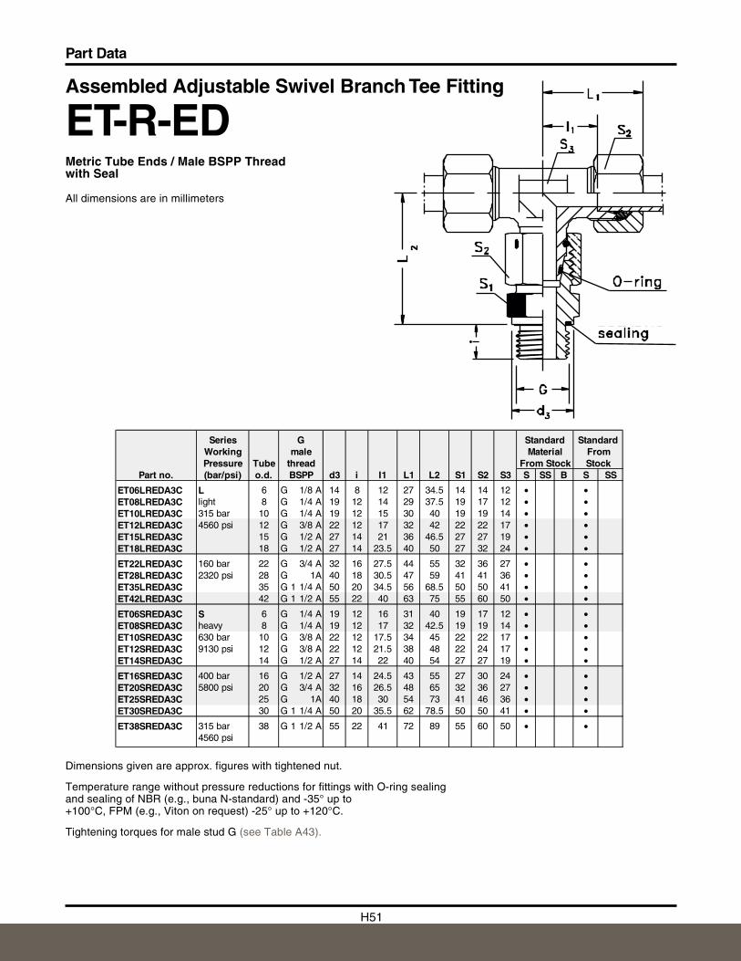
H51
Part Data
Assembled Adjustable Swivel Branch Tee Fitting
ET-R-EDMetric Tube Ends / Male BSPP Threadwith Seal
All dimensions are in millimeters
Dimensions given are approx. figures with tightened nut.
Temperature range without pressure reductions for fittings with O-ring sealingand sealing of NBR (e.g., buna N-standard) and -35° up to+100°C, FPM (e.g., Viton on request) -25° up to +120°C.
Tightening torques for male stud G (see Table A43).
Series G Standard StandardWorking male Material FromPressure Tube thread From Stock Stock
Part no. (bar/psi) o.d. BSPP d3 i I1 L1 L2 S1 S2 S3 S SS B S SS
ET06LREDA3C L 6 G 1/8 A 14 8 12 27 34.5 14 14 12 • •ET08LREDA3C light 8 G 1/4 A 19 12 14 29 37.5 19 17 12 • •ET10LREDA3C 315 bar 10 G 1/4 A 19 12 15 30 40 19 19 14 • •ET12LREDA3C 4560 psi 12 G 3/8 A 22 12 17 32 42 22 22 17 • •ET15LREDA3C 15 G 1/2 A 27 14 21 36 46.5 27 27 19 • •ET18LREDA3C 18 G 1/2 A 27 14 23.5 40 50 27 32 24 • •
ET22LREDA3C 160 bar 22 G 3/4 A 32 16 27.5 44 55 32 36 27 • •ET28LREDA3C 2320 psi 28 G 1A 40 18 30.5 47 59 41 41 36 • •ET35LREDA3C 35 G 1 1/4 A 50 20 34.5 56 68.5 50 50 41 • •ET42LREDA3C 42 G 1 1/2 A 55 22 40 63 75 55 60 50 • •
ET06SREDA3C S 6 G 1/4 A 19 12 16 31 40 19 17 12 • •ET08SREDA3C heavy 8 G 1/4 A 19 12 17 32 42.5 19 19 14 • •ET10SREDA3C 630 bar 10 G 3/8 A 22 12 17.5 34 45 22 22 17 • •ET12SREDA3C 9130 psi 12 G 3/8 A 22 12 21.5 38 48 22 24 17 • •ET14SREDA3C 14 G 1/2 A 27 14 22 40 54 27 27 19 • •
ET16SREDA3C 400 bar 16 G 1/2 A 27 14 24.5 43 55 27 30 24 • •ET20SREDA3C 5800 psi 20 G 3/4 A 32 16 26.5 48 65 32 36 27 • •ET25SREDA3C 25 G 1A 40 18 30 54 73 41 46 36 • •ET30SREDA3C 30 G 1 1/4 A 50 20 35.5 62 78.5 50 50 41 • •
ET38SREDA3C 315 bar 38 G 1 1/2 A 55 22 41 72 89 55 60 50 • •4560 psi
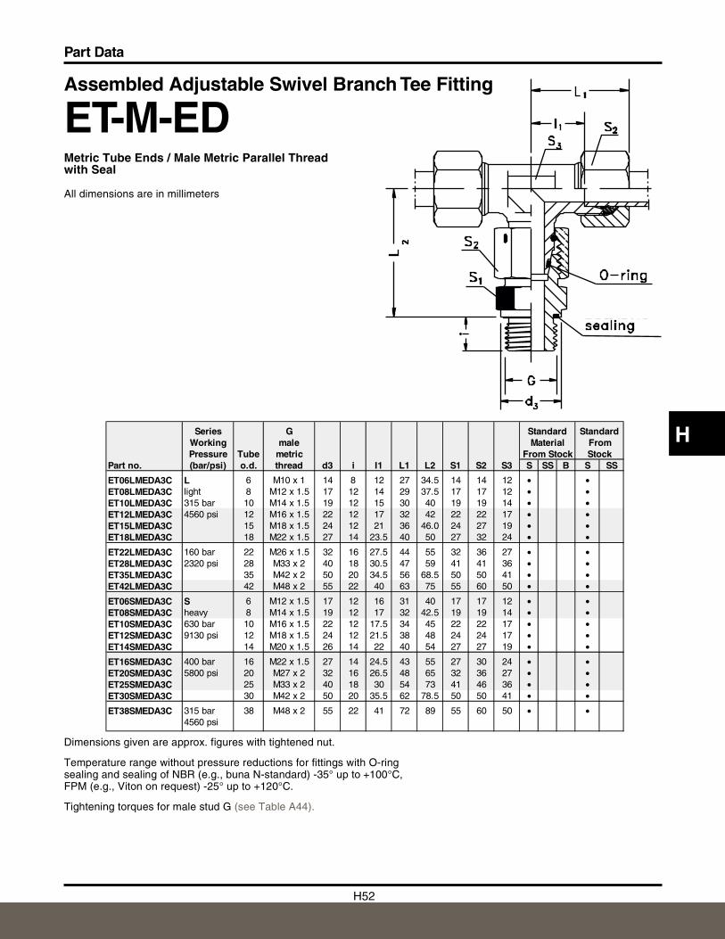
H52
Part Data
H
Assembled Adjustable Swivel Branch Tee Fitting
ET-M-EDMetric Tube Ends / Male Metric Parallel Threadwith Seal
All dimensions are in millimeters
Dimensions given are approx. figures with tightened nut.
Temperature range without pressure reductions for fittings with O-ringsealing and sealing of NBR (e.g., buna N-standard) -35° up to +100°C,FPM (e.g., Viton on request) -25° up to +120°C.
Tightening torques for male stud G (see Table A44).
Series G Standard StandardWorking male Material FromPressure Tube metric From Stock Stock
Part no. (bar/psi) o.d. thread d3 i I1 L1 L2 S1 S2 S3 S SS B S SS
ET06LMEDA3C L 6 M10 x 1 14 8 12 27 34.5 14 14 12 • •ET08LMEDA3C light 8 M12 x 1.5 17 12 14 29 37.5 17 17 12 • •ET10LMEDA3C 315 bar 10 M14 x 1.5 19 12 15 30 40 19 19 14 • •ET12LMEDA3C 4560 psi 12 M16 x 1.5 22 12 17 32 42 22 22 17 • •ET15LMEDA3C 15 M18 x 1.5 24 12 21 36 46.0 24 27 19 • •ET18LMEDA3C 18 M22 x 1.5 27 14 23.5 40 50 27 32 24 • •
ET22LMEDA3C 160 bar 22 M26 x 1.5 32 16 27.5 44 55 32 36 27 • •ET28LMEDA3C 2320 psi 28 M33 x 2 40 18 30.5 47 59 41 41 36 • •ET35LMEDA3C 35 M42 x 2 50 20 34.5 56 68.5 50 50 41 • •ET42LMEDA3C 42 M48 x 2 55 22 40 63 75 55 60 50 • •
ET06SMEDA3C S 6 M12 x 1.5 17 12 16 31 40 17 17 12 • •ET08SMEDA3C heavy 8 M14 x 1.5 19 12 17 32 42.5 19 19 14 • •ET10SMEDA3C 630 bar 10 M16 x 1.5 22 12 17.5 34 45 22 22 17 • •ET12SMEDA3C 9130 psi 12 M18 x 1.5 24 12 21.5 38 48 24 24 17 • •ET14SMEDA3C 14 M20 x 1.5 26 14 22 40 54 27 27 19 • •
ET16SMEDA3C 400 bar 16 M22 x 1.5 27 14 24.5 43 55 27 30 24 • •ET20SMEDA3C 5800 psi 20 M27 x 2 32 16 26.5 48 65 32 36 27 • •ET25SMEDA3C 25 M33 x 2 40 18 30 54 73 41 46 36 • •ET30SMEDA3C 30 M42 x 2 50 20 35.5 62 78.5 50 50 41 • •
ET38SMEDA3C 315 bar 38 M48 x 2 55 22 41 72 89 55 60 50 • •4560 psi
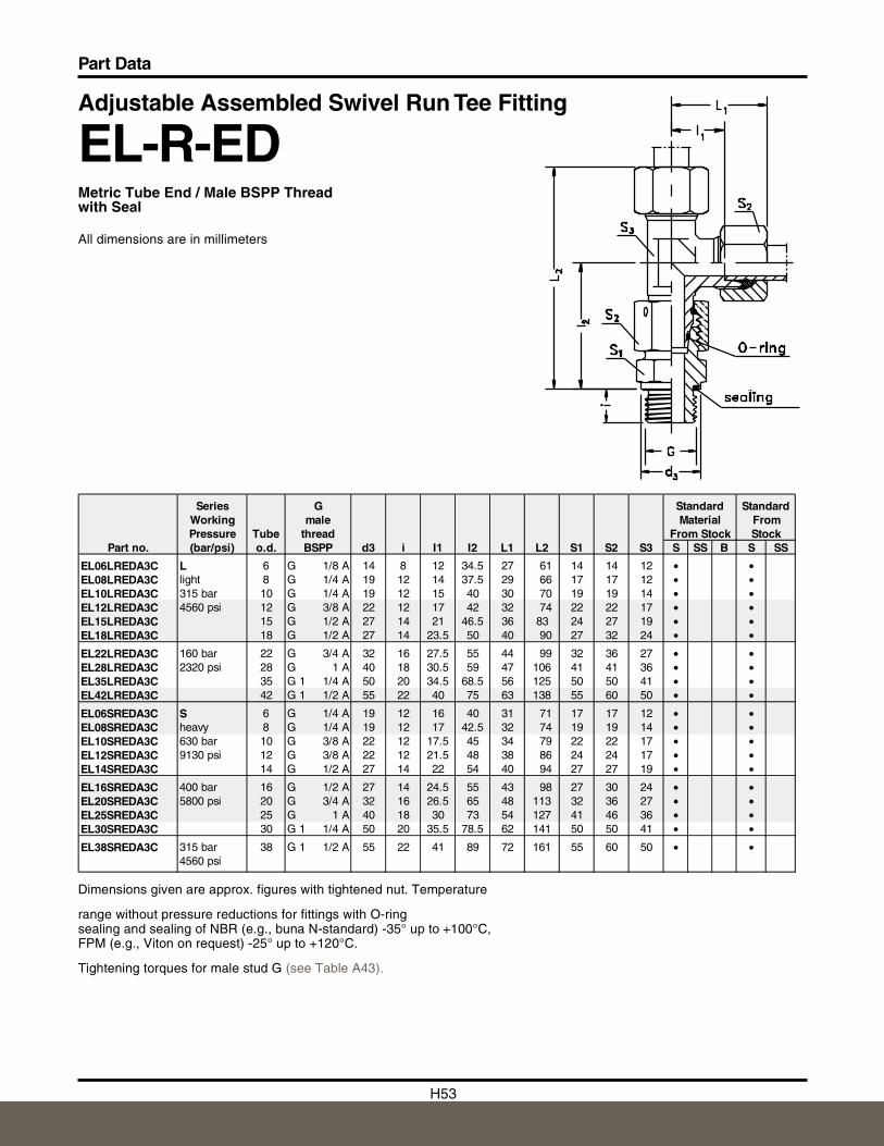
H53
Part Data
Adjustable Assembled Swivel Run Tee Fitting
EL-R-EDMetric Tube End / Male BSPP Threadwith Seal
All dimensions are in millimeters
Dimensions given are approx. figures with tightened nut. Temperature
range without pressure reductions for fittings with O-ringsealing and sealing of NBR (e.g., buna N-standard) -35° up to +100°C,FPM (e.g., Viton on request) -25° up to +120°C.
Tightening torques for male stud G (see Table A43).
Series G Standard StandardWorking male Material FromPressure Tube thread From Stock Stock
Part no. (bar/psi) o.d. BSPP d3 i I1 I2 L1 L2 S1 S2 S3 S SS B S SS
EL06LREDA3C L 6 G 1/8 A 14 8 12 34.5 27 61 14 14 12 • •EL08LREDA3C light 8 G 1/4 A 19 12 14 37.5 29 66 17 17 12 • •EL10LREDA3C 315 bar 10 G 1/4 A 19 12 15 40 30 70 19 19 14 • •EL12LREDA3C 4560 psi 12 G 3/8 A 22 12 17 42 32 74 22 22 17 • •EL15LREDA3C 15 G 1/2 A 27 14 21 46.5 36 83 24 27 19 • •EL18LREDA3C 18 G 1/2 A 27 14 23.5 50 40 90 27 32 24 • •
EL22LREDA3C 160 bar 22 G 3/4 A 32 16 27.5 55 44 99 32 36 27 • •EL28LREDA3C 2320 psi 28 G 1 A 40 18 30.5 59 47 106 41 41 36 • •EL35LREDA3C 35 G 1 1/4 A 50 20 34.5 68.5 56 125 50 50 41 • •EL42LREDA3C 42 G 1 1/2 A 55 22 40 75 63 138 55 60 50 • •
EL06SREDA3C S 6 G 1/4 A 19 12 16 40 31 71 17 17 12 • •EL08SREDA3C heavy 8 G 1/4 A 19 12 17 42.5 32 74 19 19 14 • •EL10SREDA3C 630 bar 10 G 3/8 A 22 12 17.5 45 34 79 22 22 17 • •EL12SREDA3C 9130 psi 12 G 3/8 A 22 12 21.5 48 38 86 24 24 17 • •EL14SREDA3C 14 G 1/2 A 27 14 22 54 40 94 27 27 19 • •
EL16SREDA3C 400 bar 16 G 1/2 A 27 14 24.5 55 43 98 27 30 24 • •EL20SREDA3C 5800 psi 20 G 3/4 A 32 16 26.5 65 48 113 32 36 27 • •EL25SREDA3C 25 G 1 A 40 18 30 73 54 127 41 46 36 • •EL30SREDA3C 30 G 1 1/4 A 50 20 35.5 78.5 62 141 50 50 41 • •
EL38SREDA3C 315 bar 38 G 1 1/2 A 55 22 41 89 72 161 55 60 50 • •4560 psi
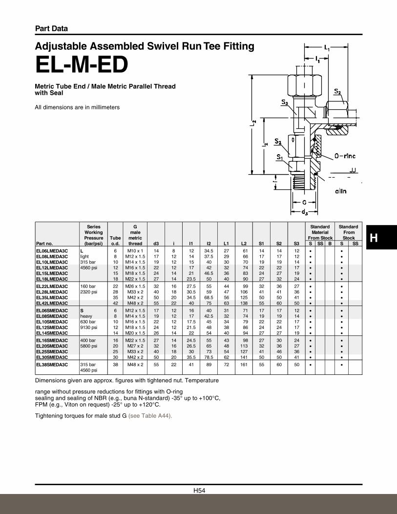
H54
Part Data
H
Adjustable Assembled Swivel Run Tee Fitting
EL-M-EDMetric Tube End / Male Metric Parallel Threadwith Seal
All dimensions are in millimeters
Dimensions given are approx. figures with tightened nut. Temperature
range without pressure reductions for fittings with O-ringsealing and sealing of NBR (e.g., buna N-standard) -35° up to +100°C,FPM (e.g., Viton on request) -25° up to +120°C.
Tightening torques for male stud G (see Table A44).
Series G Standard StandardWorking male Material FromPressure Tube metric From Stock
Part no. (bar/psi) o.d. thread d3 i I1 I2 L1 L2 S1 S2 S3 S SS B S SS
EL06LMEDA3C L 6 M10 x 1 14 8 12 34.5 27 61 14 14 12 • •EL08LMEDA3C light 8 M12 x 1.5 17 12 14 37.5 29 66 17 17 12 • •EL10LMEDA3C 315 bar 10 M14 x 1.5 19 12 15 40 30 70 19 19 14 • •EL12LMEDA3C 4560 psi 12 M16 x 1.5 22 12 17 42 32 74 22 22 17 • •EL15LMEDA3C 15 M18 x 1.5 24 14 21 46.5 36 83 24 27 19 • •EL18LMEDA3C 18 M22 x 1.5 27 14 23.5 50 40 90 27 32 24 • •EL22LMEDA3C 160 bar 22 M26 x 1.5 32 16 27.5 55 44 99 32 36 27 • •EL28LMEDA3C 2320 psi 28 M33 x 2 40 18 30.5 59 47 106 41 41 36 • •EL35LMEDA3C 35 M42 x 2 50 20 34.5 68.5 56 125 50 50 41 • •EL42LMEDA3C 42 M48 x 2 55 22 40 75 63 138 55 60 50 • •EL06SMEDA3C S 6 M12 x 1.5 17 12 16 40 31 71 17 17 12 • •EL08SMEDA3C heavy 8 M14 x 1.5 19 12 17 42.5 32 74 19 19 14 • •EL10SMEDA3C 630 bar 10 M16 x 1.5 22 12 17.5 45 34 79 22 22 17 • •EL12SMEDA3C 9130 psi 12 M18 x 1.5 24 12 21.5 48 38 86 24 24 17 • •EL14SMEDA3C 14 M20 x 1.5 26 14 22 54 40 94 27 27 19 • •EL16SMEDA3C 400 bar 16 M22 x 1.5 27 14 24.5 55 43 98 27 30 24 • •EL20SMEDA3C 5800 psi 20 M27 x 2 32 16 26.5 65 48 113 32 36 27 • •EL25SMEDA3C 25 M33 x 2 40 18 30 73 54 127 41 46 36 • •EL30SMEDA3C 30 M42 x 2 50 20 35.5 78.5 62 141 50 50 41 • •EL38SMEDA3C 315 bar 38 M48 x 2 55 22 41 89 72 161 55 60 50 • •
4560 psi
Stock
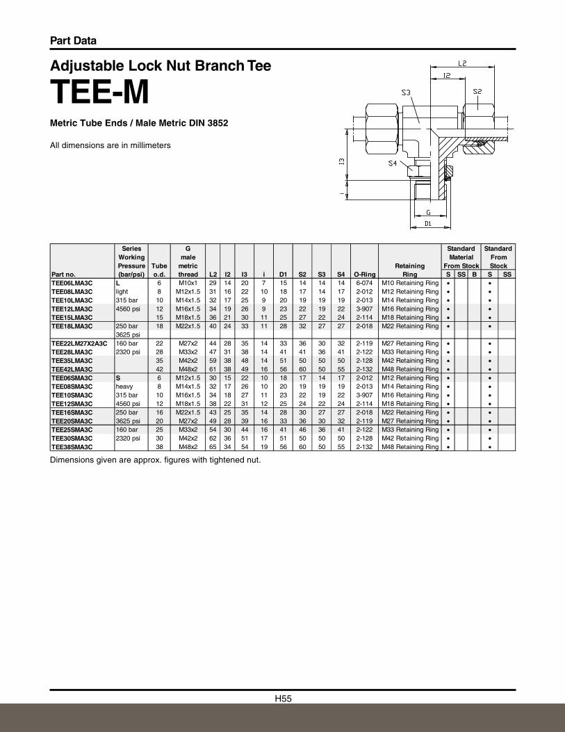
H55
Part Data
Adjustable Lock Nut Branch Tee
TEE-MMetric Tube Ends / Male Metric DIN 3852
All dimensions are in millimeters
Dimensions given are approx. figures with tightened nut.
Series G Standard StandardWorking male Material FromPressure Tube metric Retaining From Stock Stock
Part no. (bar/psi) o.d. thread L2 I2 I3 i D1 S2 S3 S4 O-Ring Ring S SS B S SSTEE06LMA3C L 6 M10x1 29 14 20 7 15 14 14 14 6-074 M10 Retaining Ring • •TEE08LMA3C light 8 M12x1.5 31 16 22 10 18 17 14 17 2-012 M12 Retaining Ring • •TEE10LMA3C 315 bar 10 M14x1.5 32 17 25 9 20 19 19 19 2-013 M14 Retaining Ring • •TEE12LMA3C 4560 psi 12 M16x1.5 34 19 26 9 23 22 19 22 3-907 M16 Retaining Ring • •TEE15LMA3C 15 M18x1.5 36 21 30 11 25 27 22 24 2-114 M18 Retaining Ring • •TEE18LMA3C 250 bar 18 M22x1.5 40 24 33 11 28 32 27 27 2-018 M22 Retaining Ring • •
3625 psiTEE22LM27X2A3C 160 bar 22 M27x2 44 28 35 14 33 36 30 32 2-119 M27 Retaining Ring • •TEE28LMA3C 2320 psi 28 M33x2 47 31 38 14 41 41 36 41 2-122 M33 Retaining Ring • •TEE35LMA3C 35 M42x2 59 38 48 14 51 50 50 50 2-128 M42 Retaining Ring • •TEE42LMA3C 42 M48x2 61 38 49 16 56 60 50 55 2-132 M48 Retaining Ring • •TEE06SMA3C S 6 M12x1.5 30 15 22 10 18 17 14 17 2-012 M12 Retaining Ring • •TEE08SMA3C heavy 8 M14x1.5 32 17 26 10 20 19 19 19 2-013 M14 Retaining Ring • •TEE10SMA3C 315 bar 10 M16x1.5 34 18 27 11 23 22 19 22 3-907 M16 Retaining Ring • •TEE12SMA3C 4560 psi 12 M18x1.5 38 22 31 12 25 24 22 24 2-114 M18 Retaining Ring • •TEE16SMA3C 250 bar 16 M22x1.5 43 25 35 14 28 30 27 27 2-018 M22 Retaining Ring • •TEE20SMA3C 3625 psi 20 M27x2 49 28 39 16 33 36 30 32 2-119 M27 Retaining Ring • •TEE25SMA3C 160 bar 25 M33x2 54 30 44 16 41 46 36 41 2-122 M33 Retaining Ring • •TEE30SMA3C 2320 psi 30 M42x2 62 36 51 17 51 50 50 50 2-128 M42 Retaining Ring • •TEE38SMA3C 38 M48x2 65 34 54 19 56 60 50 55 2-132 M48 Retaining Ring • •
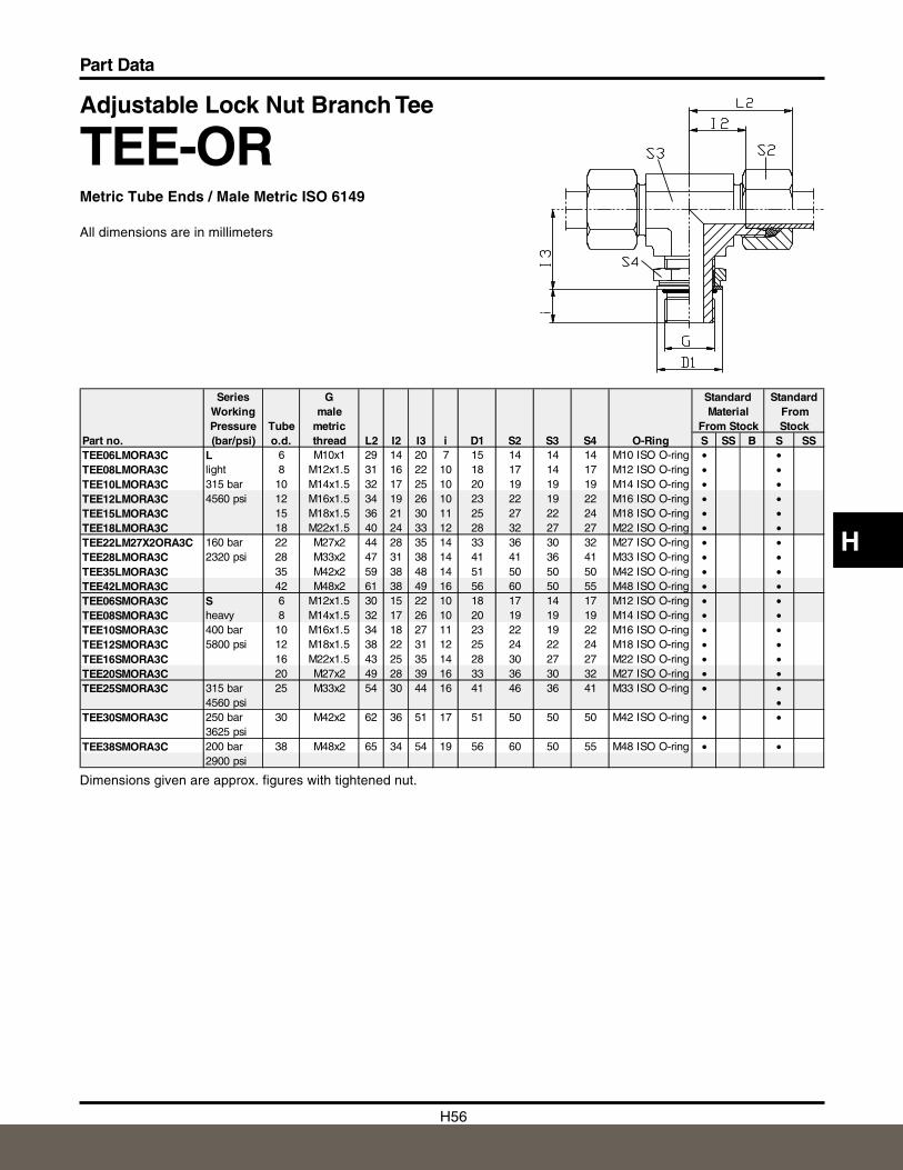
H56
Part Data
H
Adjustable Lock Nut Branch Tee
TEE-ORMetric Tube Ends / Male Metric ISO 6149
All dimensions are in millimeters
Dimensions given are approx. figures with tightened nut.
Series G Standard StandardWorking male Material FromPressure Tube metric From Stock Stock
Part no. (bar/psi) o.d. thread L2 I2 I3 i D1 S2 S3 S4 O-Ring S SS B S SSTEE06LMORA3C L 6 M10x1 29 14 20 7 15 14 14 14 M10 ISO O-ring • •TEE08LMORA3C light 8 M12x1.5 31 16 22 10 18 17 14 17 M12 ISO O-ring • •TEE10LMORA3C 315 bar 10 M14x1.5 32 17 25 10 20 19 19 19 M14 ISO O-ring • •TEE12LMORA3C 4560 psi 12 M16x1.5 34 19 26 10 23 22 19 22 M16 ISO O-ring • •TEE15LMORA3C 15 M18x1.5 36 21 30 11 25 27 22 24 M18 ISO O-ring • •TEE18LMORA3C 18 M22x1.5 40 24 33 12 28 32 27 27 M22 ISO O-ring • •TEE22LM27X2ORA3C 160 bar 22 M27x2 44 28 35 14 33 36 30 32 M27 ISO O-ring • •TEE28LMORA3C 2320 psi 28 M33x2 47 31 38 14 41 41 36 41 M33 ISO O-ring • •TEE35LMORA3C 35 M42x2 59 38 48 14 51 50 50 50 M42 ISO O-ring • •TEE42LMORA3C 42 M48x2 61 38 49 16 56 60 50 55 M48 ISO O-ring • •TEE06SMORA3C S 6 M12x1.5 30 15 22 10 18 17 14 17 M12 ISO O-ring • •TEE08SMORA3C heavy 8 M14x1.5 32 17 26 10 20 19 19 19 M14 ISO O-ring • •TEE10SMORA3C 400 bar 10 M16x1.5 34 18 27 11 23 22 19 22 M16 ISO O-ring • •TEE12SMORA3C 5800 psi 12 M18x1.5 38 22 31 12 25 24 22 24 M18 ISO O-ring • •TEE16SMORA3C 16 M22x1.5 43 25 35 14 28 30 27 27 M22 ISO O-ring • •TEE20SMORA3C 20 M27x2 49 28 39 16 33 36 30 32 M27 ISO O-ring • •TEE25SMORA3C 315 bar 25 M33x2 54 30 44 16 41 46 36 41 M33 ISO O-ring • •
4560 psi •TEE30SMORA3C 250 bar 30 M42x2 62 36 51 17 51 50 50 50 M42 ISO O-ring • •
3625 psiTEE38SMORA3C 200 bar 38 M48x2 65 34 54 19 56 60 50 55 M48 ISO O-ring • •
2900 psi
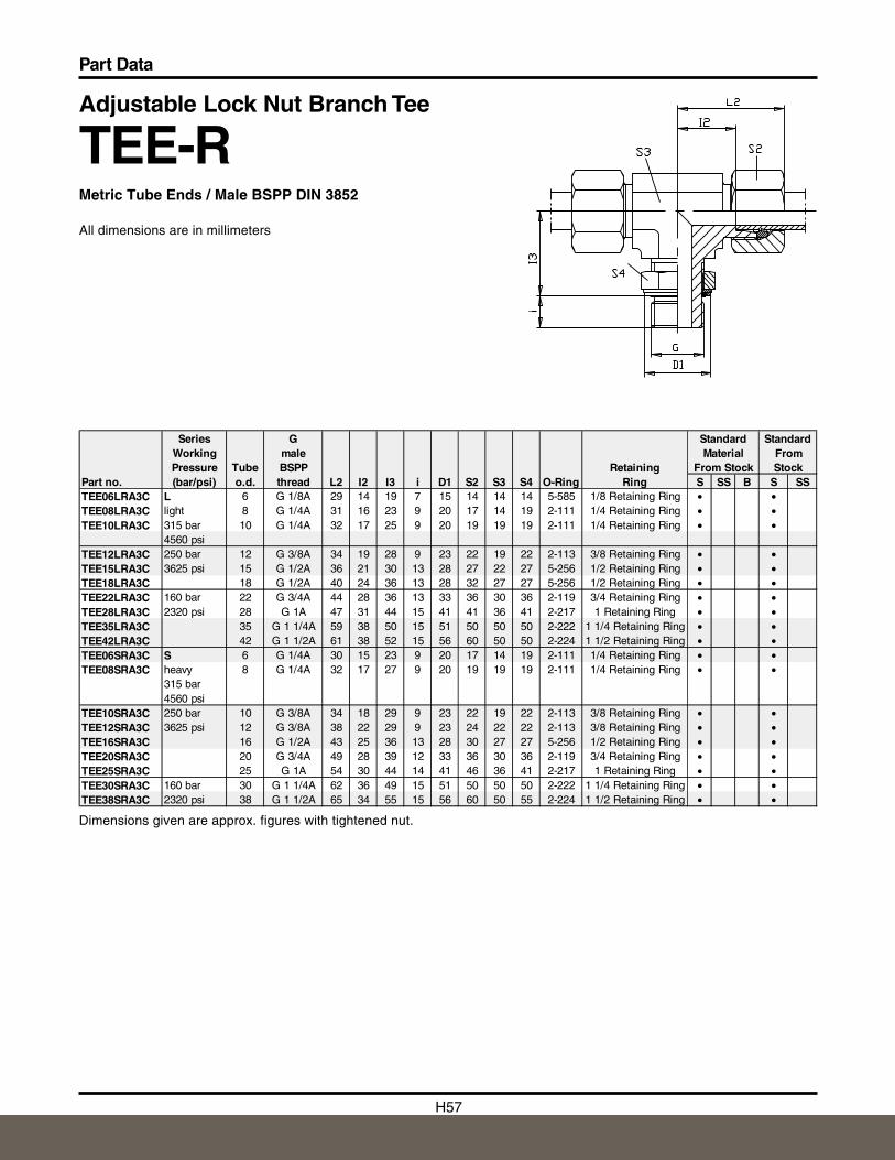
H57
Part Data
Adjustable Lock Nut Branch Tee
TEE-RMetric Tube Ends / Male BSPP DIN 3852
All dimensions are in millimeters
Dimensions given are approx. figures with tightened nut.
Series G Standard StandardWorking male Material FromPressure Tube BSPP Retaining From Stock Stock
Part no. (bar/psi) o.d. thread L2 I2 I3 i D1 S2 S3 S4 O-Ring Ring S SS B S SSTEE06LRA3C L 6 G 1/8A 29 14 19 7 15 14 14 14 5-585 1/8 Retaining Ring • •TEE08LRA3C light 8 G 1/4A 31 16 23 9 20 17 14 19 2-111 1/4 Retaining Ring • •TEE10LRA3C 315 bar 10 G 1/4A 32 17 25 9 20 19 19 19 2-111 1/4 Retaining Ring • •
4560 psiTEE12LRA3C 250 bar 12 G 3/8A 34 19 28 9 23 22 19 22 2-113 3/8 Retaining Ring • •TEE15LRA3C 3625 psi 15 G 1/2A 36 21 30 13 28 27 22 27 5-256 1/2 Retaining Ring • •TEE18LRA3C 18 G 1/2A 40 24 36 13 28 32 27 27 5-256 1/2 Retaining Ring • •TEE22LRA3C 160 bar 22 G 3/4A 44 28 36 13 33 36 30 36 2-119 3/4 Retaining Ring • •TEE28LRA3C 2320 psi 28 G 1A 47 31 44 15 41 41 36 41 2-217 1 Retaining Ring • •TEE35LRA3C 35 G 1 1/4A 59 38 50 15 51 50 50 50 2-222 1 1/4 Retaining Ring • •TEE42LRA3C 42 G 1 1/2A 61 38 52 15 56 60 50 50 2-224 1 1/2 Retaining Ring • •TEE06SRA3C S 6 G 1/4A 30 15 23 9 20 17 14 19 2-111 1/4 Retaining Ring • •TEE08SRA3C heavy 8 G 1/4A 32 17 27 9 20 19 19 19 2-111 1/4 Retaining Ring • •
315 bar4560 psi
TEE10SRA3C 250 bar 10 G 3/8A 34 18 29 9 23 22 19 22 2-113 3/8 Retaining Ring • •TEE12SRA3C 3625 psi 12 G 3/8A 38 22 29 9 23 24 22 22 2-113 3/8 Retaining Ring • •TEE16SRA3C 16 G 1/2A 43 25 36 13 28 30 27 27 5-256 1/2 Retaining Ring • •TEE20SRA3C 20 G 3/4A 49 28 39 12 33 36 30 36 2-119 3/4 Retaining Ring • •TEE25SRA3C 25 G 1A 54 30 44 14 41 46 36 41 2-217 1 Retaining Ring • •TEE30SRA3C 160 bar 30 G 1 1/4A 62 36 49 15 51 50 50 50 2-222 1 1/4 Retaining Ring • •TEE38SRA3C 2320 psi 38 G 1 1/2A 65 34 55 15 56 60 50 55 2-224 1 1/2 Retaining Ring • •
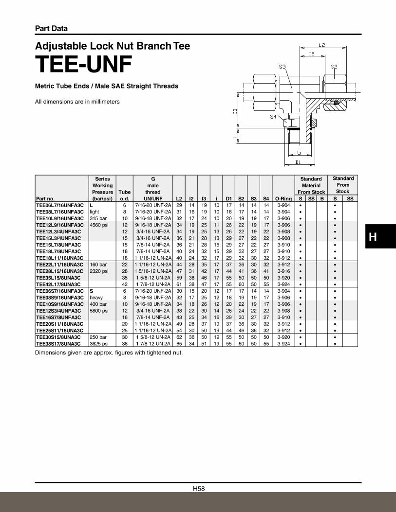
H58
Part Data
H
Adjustable Lock Nut Branch Tee
TEE-UNFMetric Tube Ends / Male SAE Straight Threads
All dimensions are in millimeters
Dimensions given are approx. figures with tightened nut.
Series G StandardWorking male MaterialPressure Tube thread From Stock
Part no. (bar/psi) o.d. UN/UNF L2 I2 I3 i D1 S2 S3 S4 O-Ring S SS B S SSTEE06L7/16UNFA3C L 6 7/16-20 UNF-2A 29 14 19 10 17 14 14 14 3-904 • •TEE08L7/16UNFA3C light 8 7/16-20 UNF-2A 31 16 19 10 18 17 14 14 3-904 • •TEE10L9/16UNFA3C 315 bar 10 9/16-18 UNF-2A 32 17 24 10 20 19 19 17 3-906 • •TEE12L9/16UNFA3C 4560 psi 12 9/16-18 UNF-2A 34 19 25 11 26 22 19 17 3-906 • •TEE12L3/4UNFA3C 12 3/4-16 UNF-2A 34 19 25 13 26 22 19 22 3-908 • •TEE15L3/4UNFA3C 15 3/4-16 UNF-2A 36 21 28 13 29 27 22 22 3-908 • •TEE15L7/8UNFA3C 15 7/8-14 UNF-2A 36 21 28 15 29 27 22 27 3-910 • •TEE18L7/8UNFA3C 18 7/8-14 UNF-2A 40 24 32 15 29 32 27 27 3-910 • •TEE18L11/16UNA3C 18 1 1/16-12 UN-2A 40 24 32 17 29 32 30 32 3-912 • •TEE22L11/16UNA3C 160 bar 22 1 1/16-12 UN-2A 44 28 35 17 37 36 30 32 3-912 • •TEE28L15/16UNA3C 2320 psi 28 1 5/16-12 UN-2A 47 31 42 17 44 41 36 41 3-916 • •TEE35L15/8UNA3C 35 1 5/8-12 UN-2A 59 38 46 17 55 50 50 50 3-920 • •TEE42L17/8UNA3C 42 1 7/8-12 UN-2A 61 38 47 17 55 60 50 55 3-924 • •TEE06S7/16UNFA3C S 6 7/16-20 UNF-2A 30 15 20 12 17 17 14 14 3-904 • •TEE08S9/16UNFA3C heavy 8 9/16-18 UNF-2A 32 17 25 12 18 19 19 17 3-906 • •TEE10S9/16UNFA3C 400 bar 10 9/16-18 UNF-2A 34 18 26 12 20 22 19 17 3-906 • •TEE12S3/4UNFA3C 5800 psi 12 3/4-16 UNF-2A 38 22 30 14 26 24 22 22 3-908 • •TEE16S7/8UNFA3C 16 7/8-14 UNF-2A 43 25 34 16 29 30 27 27 3-910 • •TEE20S11/16UNA3C 20 1 1/16-12 UN-2A 49 28 37 19 37 36 30 32 3-912 • •TEE25S11/16UNA3C 25 1 1/16-12 UN-2A 54 30 50 19 44 46 36 32 3-912 • •TEE30S15/8UNA3C 250 bar 30 1 5/8-12 UN-2A 62 36 50 19 55 50 50 50 3-920 • •TEE38S17/8UNA3C 3625 psi 38 1 7/8-12 UN-2A 65 34 51 19 55 60 50 55 3-924 • •
Standard From Stock
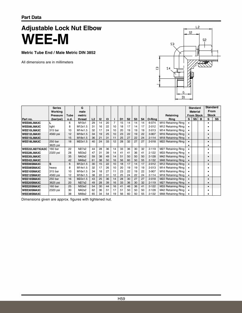
H59
Part Data
Adjustable Lock Nut Elbow
WEE-MMetric Tube End / Male Metric DIN 3852
All dimensions are in millimeters
Dimensions given are approx. figures with tightened nut.
Series G StandardWorking male MaterialPressure Tube metric Retaining From Stock
Part no. (bar/psi) o.d. thread L2 I2 I3 i D1 S2 S3 S4 O-Ring Ring S SS B S SSWEE06LMA3C L 6 M10x1 29 14 20 7 15 14 14 14 6-074 M10 Retaining Ring • •WEE08LMA3C light 8 M12x1.5 31 16 22 10 18 17 14 17 2-012 M12 Retaining Ring • •WEE10LMA3C 315 bar 10 M14x1.5 32 17 24 10 20 19 19 19 2-013 M14 Retaining Ring • •WEE12LMA3C 4560 psi 12 M16x1.5 34 19 25 10 23 22 19 22 3-907 M16 Retaining Ring • •WEE15LMA3C 15 M18x1.5 36 21 31 11 25 27 22 24 2-114 M18 Retaining Ring • •WEE18LMA3C 250 bar 18 M22x1.5 40 24 33 12 28 32 27 27 2-018 M22 Retaining Ring • •
3625 psi • •WEE22LM27X2A3C 160 bar 22 M27x2 44 28 36 14 33 36 30 32 2-119 M27 Retaining Ring • •WEE28LMA3C 2320 psi 28 M33x2 47 31 39 14 41 41 36 41 2-122 M33 Retaining Ring • •WEE35LMA3C 35 M42x2 59 38 49 14 51 50 50 50 2-128 M42 Retaining Ring • •WEE42LMA3C 42 M48x2 61 38 50 16 56 60 50 55 2-132 M48 Retaining Ring • •WEE06SMA3C S 6 M12x1.5 30 15 22 10 18 17 14 17 2-012 M12 Retaining Ring • •WEE08SMA3C heavy 8 M14x1.5 32 17 26 10 20 19 19 19 2-013 M14 Retaining Ring • •WEE10SMA3C 315 bar 10 M16x1.5 34 18 27 11 23 22 19 22 3-907 M16 Retaining Ring • •WEE12SMA3C 4560 psi 12 M18x1.5 38 22 31 12 25 24 22 24 2-114 M18 Retaining Ring • •WEE16SMA3C 250 bar 16 M22x1.5 43 25 36 14 28 30 27 27 2-018 M22 Retaining Ring • •WEE20SMA3C 3625 psi 20 M27x2 49 28 39 16 33 36 30 32 2-119 M27 Retaining Ring • •WEE25SMA3C 160 bar 25 M33x2 54 30 44 16 41 46 36 41 2-122 M33 Retaining Ring • •WEE30SMA3C 2320 psi 30 M42x2 62 36 51 17 51 50 50 50 2-128 M42 Retaining Ring • •WEE38SMA3C 38 M48x2 65 34 54 19 56 60 50 55 2-132 M48 Retaining Ring • •
Standard From Stock
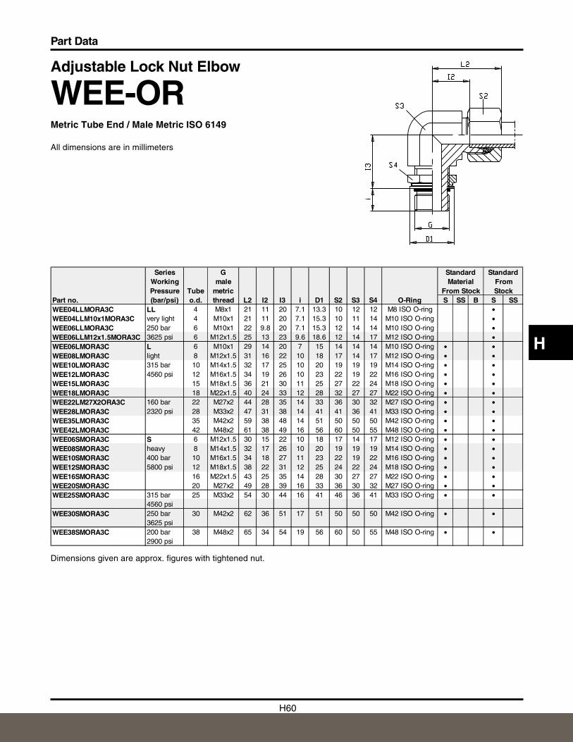
H60
Part Data
H
Adjustable Lock Nut Elbow
WEE-ORMetric Tube End / Male Metric ISO 6149
All dimensions are in millimeters
Dimensions given are approx. figures with tightened nut.
Series G Standard StandardWorking male Material FromPressure Tube metric From Stock Stock
Part no. (bar/psi) o.d. thread L2 I2 I3 i D1 S2 S3 S4 O-Ring S SS B S SSWEE04LLMORA3C LL 4 M8x1 21 11 20 7.1 13.3 10 12 12 M8 ISO O-ring •WEE04LLM10x1MORA3C very light 4 M10x1 21 11 20 7.1 15.3 10 11 14 M10 ISO O-ring •WEE06LLMORA3C 250 bar 6 M10x1 22 9.8 20 7.1 15.3 12 14 14 M10 ISO O-ring •WEE06LLM12x1.5MORA3C 3625 psi 6 M12x1.5 25 13 23 9.6 18.6 12 14 17 M12 ISO O-ring •WEE06LMORA3C L 6 M10x1 29 14 20 7 15 14 14 14 M10 ISO O-ring • •WEE08LMORA3C light 8 M12x1.5 31 16 22 10 18 17 14 17 M12 ISO O-ring • •WEE10LMORA3C 315 bar 10 M14x1.5 32 17 25 10 20 19 19 19 M14 ISO O-ring • •WEE12LMORA3C 4560 psi 12 M16x1.5 34 19 26 10 23 22 19 22 M16 ISO O-ring • •WEE15LMORA3C 15 M18x1.5 36 21 30 11 25 27 22 24 M18 ISO O-ring • •WEE18LMORA3C 18 M22x1.5 40 24 33 12 28 32 27 27 M22 ISO O-ring • •WEE22LM27X2ORA3C 160 bar 22 M27x2 44 28 35 14 33 36 30 32 M27 ISO O-ring • •WEE28LMORA3C 2320 psi 28 M33x2 47 31 38 14 41 41 36 41 M33 ISO O-ring • •WEE35LMORA3C 35 M42x2 59 38 48 14 51 50 50 50 M42 ISO O-ring • •WEE42LMORA3C 42 M48x2 61 38 49 16 56 60 50 55 M48 ISO O-ring • •WEE06SMORA3C S 6 M12x1.5 30 15 22 10 18 17 14 17 M12 ISO O-ring • •WEE08SMORA3C heavy 8 M14x1.5 32 17 26 10 20 19 19 19 M14 ISO O-ring • •WEE10SMORA3C 400 bar 10 M16x1.5 34 18 27 11 23 22 19 22 M16 ISO O-ring • •WEE12SMORA3C 5800 psi 12 M18x1.5 38 22 31 12 25 24 22 24 M18 ISO O-ring • •WEE16SMORA3C 16 M22x1.5 43 25 35 14 28 30 27 27 M22 ISO O-ring • •WEE20SMORA3C 20 M27x2 49 28 39 16 33 36 30 32 M27 ISO O-ring • •WEE25SMORA3C 315 bar 25 M33x2 54 30 44 16 41 46 36 41 M33 ISO O-ring • •
4560 psiWEE30SMORA3C 250 bar 30 M42x2 62 36 51 17 51 50 50 50 M42 ISO O-ring • •
3625 psiWEE38SMORA3C 200 bar 38 M48x2 65 34 54 19 56 60 50 55 M48 ISO O-ring • •
2900 psi
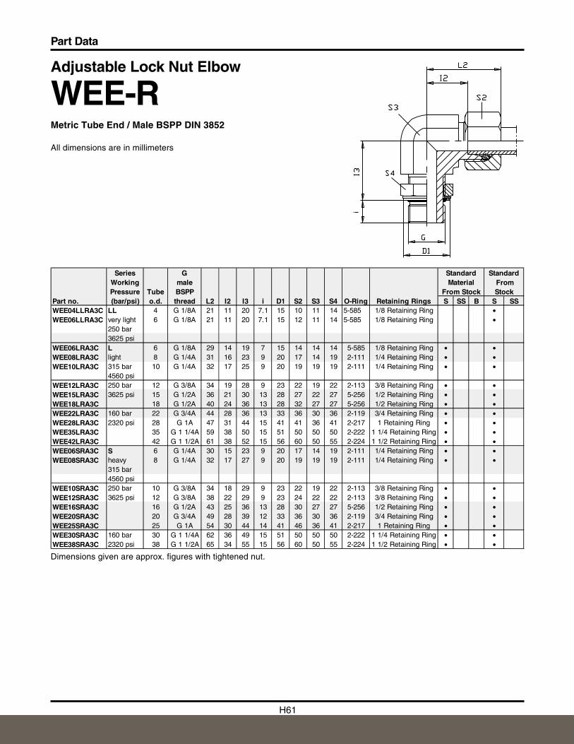
H61
Part Data
Adjustable Lock Nut Elbow
WEE-RMetric Tube End / Male BSPP DIN 3852
All dimensions are in millimeters
Dimensions given are approx. figures with tightened nut.
Series G Standard StandardWorking male Material FromPressure Tube BSPP From Stock Stock
Part no. (bar/psi) o.d. thread L2 I2 I3 i D1 S2 S3 S4 O-Ring Retaining Rings S SS B S SSWEE04LLRA3C LL 4 G 1/8A 21 11 20 7.1 15 10 11 14 5-585 1/8 Retaining Ring •WEE06LLRA3C very light 6 G 1/8A 21 11 20 7.1 15 12 11 14 5-585 1/8 Retaining Ring •
250 bar3625 psi
WEE06LRA3C L 6 G 1/8A 29 14 19 7 15 14 14 14 5-585 1/8 Retaining Ring • •WEE08LRA3C light 8 G 1/4A 31 16 23 9 20 17 14 19 2-111 1/4 Retaining Ring • •WEE10LRA3C 315 bar 10 G 1/4A 32 17 25 9 20 19 19 19 2-111 1/4 Retaining Ring • •
4560 psiWEE12LRA3C 250 bar 12 G 3/8A 34 19 28 9 23 22 19 22 2-113 3/8 Retaining Ring • •WEE15LRA3C 3625 psi 15 G 1/2A 36 21 30 13 28 27 22 27 5-256 1/2 Retaining Ring • •WEE18LRA3C 18 G 1/2A 40 24 36 13 28 32 27 27 5-256 1/2 Retaining Ring • •WEE22LRA3C 160 bar 22 G 3/4A 44 28 36 13 33 36 30 36 2-119 3/4 Retaining Ring • •WEE28LRA3C 2320 psi 28 G 1A 47 31 44 15 41 41 36 41 2-217 1 Retaining Ring • •WEE35LRA3C 35 G 1 1/4A 59 38 50 15 51 50 50 50 2-222 1 1/4 Retaining Ring • •WEE42LRA3C 42 G 1 1/2A 61 38 52 15 56 60 50 55 2-224 1 1/2 Retaining Ring • •WEE06SRA3C S 6 G 1/4A 30 15 23 9 20 17 14 19 2-111 1/4 Retaining Ring • •WEE08SRA3C heavy 8 G 1/4A 32 17 27 9 20 19 19 19 2-111 1/4 Retaining Ring • •
315 bar4560 psi
WEE10SRA3C 250 bar 10 G 3/8A 34 18 29 9 23 22 19 22 2-113 3/8 Retaining Ring • •WEE12SRA3C 3625 psi 12 G 3/8A 38 22 29 9 23 24 22 22 2-113 3/8 Retaining Ring • •WEE16SRA3C 16 G 1/2A 43 25 36 13 28 30 27 27 5-256 1/2 Retaining Ring • •WEE20SRA3C 20 G 3/4A 49 28 39 12 33 36 30 36 2-119 3/4 Retaining Ring • •WEE25SRA3C 25 G 1A 54 30 44 14 41 46 36 41 2-217 1 Retaining Ring • •WEE30SRA3C 160 bar 30 G 1 1/4A 62 36 49 15 51 50 50 50 2-222 1 1/4 Retaining Ring • •WEE38SRA3C 2320 psi 38 G 1 1/2A 65 34 55 15 56 60 50 55 2-224 1 1/2 Retaining Ring • •
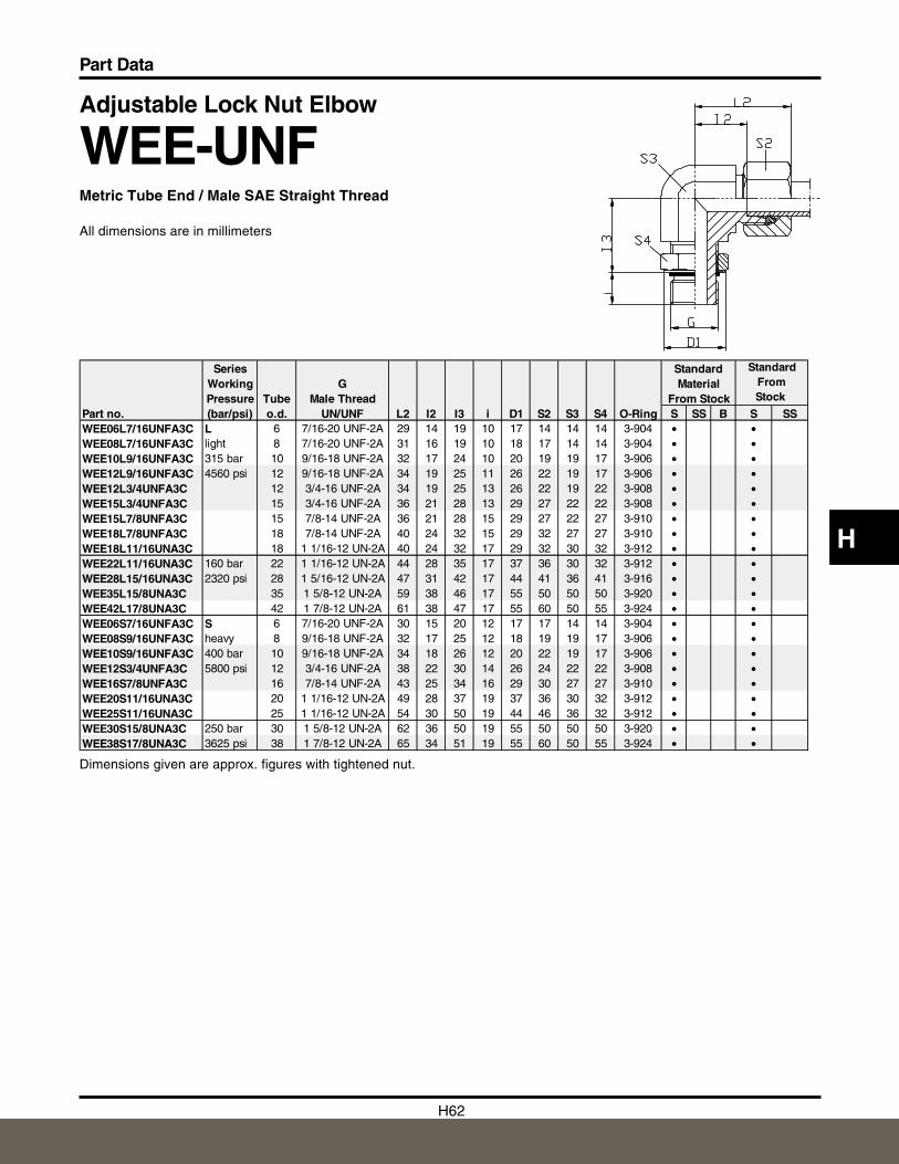
H62
Part Data
H
Adjustable Lock Nut Elbow
WEE-UNFMetric Tube End / Male SAE Straight Thread
All dimensions are in millimeters
Dimensions given are approx. figures with tightened nut.
Series StandardWorking G MaterialPressure Tube Male Thread From Stock
Part no. (bar/psi) o.d. UN/UNF L2 I2 I3 i D1 S2 S3 S4 O-Ring S SS B S SSWEE06L7/16UNFA3C L 6 7/16-20 UNF-2A 29 14 19 10 17 14 14 14 3-904 • •WEE08L7/16UNFA3C light 8 7/16-20 UNF-2A 31 16 19 10 18 17 14 14 3-904 • •WEE10L9/16UNFA3C 315 bar 10 9/16-18 UNF-2A 32 17 24 10 20 19 19 17 3-906 • •WEE12L9/16UNFA3C 4560 psi 12 9/16-18 UNF-2A 34 19 25 11 26 22 19 17 3-906 • •WEE12L3/4UNFA3C 12 3/4-16 UNF-2A 34 19 25 13 26 22 19 22 3-908 • •WEE15L3/4UNFA3C 15 3/4-16 UNF-2A 36 21 28 13 29 27 22 22 3-908 • •WEE15L7/8UNFA3C 15 7/8-14 UNF-2A 36 21 28 15 29 27 22 27 3-910 • •WEE18L7/8UNFA3C 18 7/8-14 UNF-2A 40 24 32 15 29 32 27 27 3-910 • •WEE18L11/16UNA3C 18 1 1/16-12 UN-2A 40 24 32 17 29 32 30 32 3-912 • •WEE22L11/16UNA3C 160 bar 22 1 1/16-12 UN-2A 44 28 35 17 37 36 30 32 3-912 • •WEE28L15/16UNA3C 2320 psi 28 1 5/16-12 UN-2A 47 31 42 17 44 41 36 41 3-916 • •WEE35L15/8UNA3C 35 1 5/8-12 UN-2A 59 38 46 17 55 50 50 50 3-920 • •WEE42L17/8UNA3C 42 1 7/8-12 UN-2A 61 38 47 17 55 60 50 55 3-924 • •WEE06S7/16UNFA3C S 6 7/16-20 UNF-2A 30 15 20 12 17 17 14 14 3-904 • •WEE08S9/16UNFA3C heavy 8 9/16-18 UNF-2A 32 17 25 12 18 19 19 17 3-906 • •WEE10S9/16UNFA3C 400 bar 10 9/16-18 UNF-2A 34 18 26 12 20 22 19 17 3-906 • •WEE12S3/4UNFA3C 5800 psi 12 3/4-16 UNF-2A 38 22 30 14 26 24 22 22 3-908 • •WEE16S7/8UNFA3C 16 7/8-14 UNF-2A 43 25 34 16 29 30 27 27 3-910 • •WEE20S11/16UNA3C 20 1 1/16-12 UN-2A 49 28 37 19 37 36 30 32 3-912 • •WEE25S11/16UNA3C 25 1 1/16-12 UN-2A 54 30 50 19 44 46 36 32 3-912 • •WEE30S15/8UNA3C 250 bar 30 1 5/8-12 UN-2A 62 36 50 19 55 50 50 50 3-920 • •WEE38S17/8UNA3C 3625 psi 38 1 7/8-12 UN-2A 65 34 51 19 55 60 50 55 3-924 • •
Standard From Stock
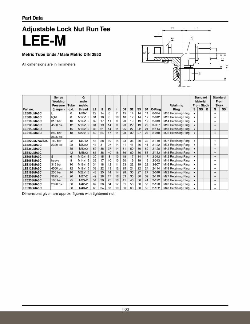
H63
Part Data
Adjustable Lock Nut Run Tee
LEE-MMetric Tube Ends / Male Metric DIN 3852
All dimensions are in millimeters
Dimensions given are approx. figures with tightened nut.
Series G Standard StandardWorking male Material FromPressure Tube metric Retaining From Stock Stock
Part no. (bar/psi) o.d. thread L2 I2 I3 i D1 S2 S3 S4 O-Ring Ring S SS B S SSLEE06LMA3C L 6 M10x1 29 14 8 7 15 14 14 14 6-074 M10 Retaining Ring • •LEE08LMA3C light 8 M12x1.5 31 16 8 10 18 17 14 17 2-012 M12 Retaining Ring • •LEE10LMA3C 315 bar 10 M14x1.5 32 17 11 9 20 19 19 19 2-013 M14 Retaining Ring • •LEE12LMA3C 4560 psi 12 M16x1.5 34 19 14 9 23 22 19 22 3-907 M16 Retaining Ring • •LEE15LMA3C 15 M18x1.5 36 21 14 11 25 27 22 24 2-114 M18 Retaining Ring • •LEE18LMA3C 250 bar 18 M22x1.5 40 24 17 11 28 32 27 27 2-018 M22 Retaining Ring • •
3625 psiLEE22LM27X2A3C 160 bar 22 M27x2 44 28 19 14 33 36 30 32 2-119 M27 Retaining Ring • •LEE28LMA3C 2320 psi 28 M33x2 47 31 27 14 41 41 36 41 2-122 M33 Retaining Ring • •LEE35LMA3C 35 M42x2 59 38 37 14 51 50 50 50 2-128 M42 Retaining Ring • •LEE42LMA3C 42 M48x2 61 38 40 16 56 60 50 55 2-132 M48 Retaining Ring • •LEE06SMA3C S 6 M12x1.5 30 15 8 10 18 17 14 17 2-012 M12 Retaining Ring • •LEE08SMA3C heavy 8 M14x1.5 32 17 10 10 20 19 19 19 2-013 M14 Retaining Ring • •LEE10SMA3C 315 bar 10 M16x1.5 34 18 12 11 23 22 19 22 3-907 M16 Retaining Ring • •LEE12SMA3C 4560 psi 12 M18x1.5 38 22 13 12 25 24 22 24 2-114 M18 Retaining Ring • •LEE16SMA3C 250 bar 16 M22x1.5 43 25 14 14 28 30 27 27 2-018 M22 Retaining Ring • •LEE20SMA3C 3625 psi 20 M27x2 49 28 17 16 33 36 30 32 2-119 M27 Retaining Ring • •LEE25SMA3C 160 bar 25 M33x2 54 30 25 16 41 46 36 41 2-122 M33 Retaining Ring • •LEE30SMA3C 2320 psi 30 M42x2 62 36 34 17 51 50 50 50 2-128 M42 Retaining Ring • •LEE38SMA3C 38 M48x2 65 34 37 19 56 60 50 55 2-132 M48 Retaining Ring • •
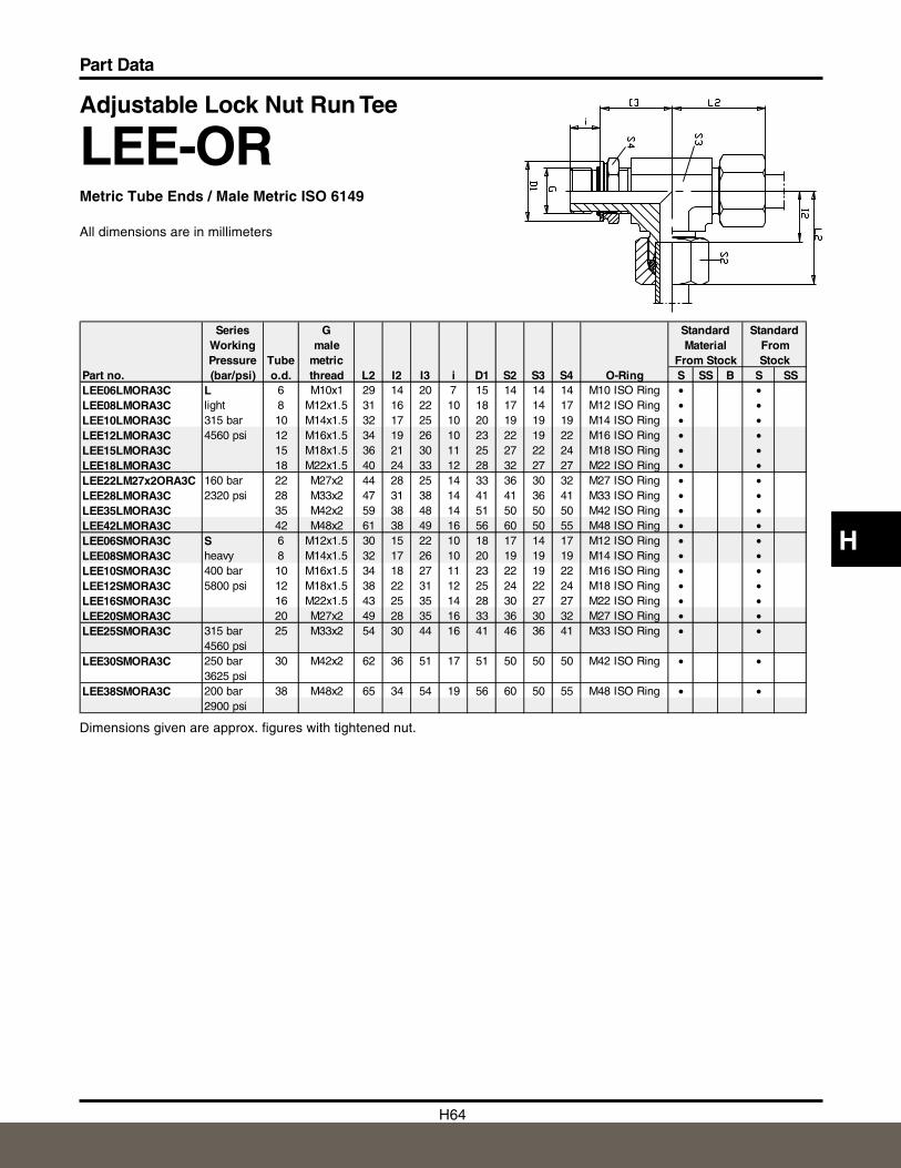
H64
Part Data
H
Adjustable Lock Nut Run Tee
LEE-ORMetric Tube Ends / Male Metric ISO 6149
All dimensions are in millimeters
Dimensions given are approx. figures with tightened nut.
Series G Standard StandardWorking male Material FromPressure Tube metric From Stock Stock
Part no. (bar/psi) o.d. thread L2 I2 I3 i D1 S2 S3 S4 O-Ring S SS B S SSLEE06LMORA3C L 6 M10x1 29 14 20 7 15 14 14 14 M10 ISO Ring • •LEE08LMORA3C light 8 M12x1.5 31 16 22 10 18 17 14 17 M12 ISO Ring • •LEE10LMORA3C 315 bar 10 M14x1.5 32 17 25 10 20 19 19 19 M14 ISO Ring • •LEE12LMORA3C 4560 psi 12 M16x1.5 34 19 26 10 23 22 19 22 M16 ISO Ring • •LEE15LMORA3C 15 M18x1.5 36 21 30 11 25 27 22 24 M18 ISO Ring • •LEE18LMORA3C 18 M22x1.5 40 24 33 12 28 32 27 27 M22 ISO Ring • •LEE22LM27x2ORA3C 160 bar 22 M27x2 44 28 25 14 33 36 30 32 M27 ISO Ring • •LEE28LMORA3C 2320 psi 28 M33x2 47 31 38 14 41 41 36 41 M33 ISO Ring • •LEE35LMORA3C 35 M42x2 59 38 48 14 51 50 50 50 M42 ISO Ring • •LEE42LMORA3C 42 M48x2 61 38 49 16 56 60 50 55 M48 ISO Ring • •LEE06SMORA3C S 6 M12x1.5 30 15 22 10 18 17 14 17 M12 ISO Ring • •LEE08SMORA3C heavy 8 M14x1.5 32 17 26 10 20 19 19 19 M14 ISO Ring • •LEE10SMORA3C 400 bar 10 M16x1.5 34 18 27 11 23 22 19 22 M16 ISO Ring • •LEE12SMORA3C 5800 psi 12 M18x1.5 38 22 31 12 25 24 22 24 M18 ISO Ring • •LEE16SMORA3C 16 M22x1.5 43 25 35 14 28 30 27 27 M22 ISO Ring • •LEE20SMORA3C 20 M27x2 49 28 35 16 33 36 30 32 M27 ISO Ring • •LEE25SMORA3C 315 bar 25 M33x2 54 30 44 16 41 46 36 41 M33 ISO Ring • •
4560 psiLEE30SMORA3C 250 bar 30 M42x2 62 36 51 17 51 50 50 50 M42 ISO Ring • •
3625 psiLEE38SMORA3C 200 bar 38 M48x2 65 34 54 19 56 60 50 55 M48 ISO Ring • •
2900 psi
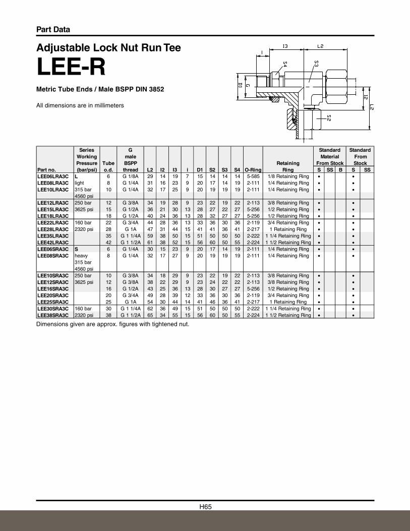
H65
Part Data
Adjustable Lock Nut Run Tee
LEE-RMetric Tube Ends / Male BSPP DIN 3852
All dimensions are in millimeters
Dimensions given are approx. figures with tightened nut.
Series G Standard StandardWorking male Material FromPressure Tube BSPP Retaining From Stock Stock
Part no. (bar/psi) o.d. thread L2 I2 I3 i D1 S2 S3 S4 O-Ring Ring S SS B S SSLEE06LRA3C L 6 G 1/8A 29 14 19 7 15 14 14 14 5-585 1/8 Retaining Ring • •LEE08LRA3C light 8 G 1/4A 31 16 23 9 20 17 14 19 2-111 1/4 Retaining Ring • •LEE10LRA3C 315 bar 10 G 1/4A 32 17 25 9 20 19 19 19 2-111 1/4 Retaining Ring • •
4560 psiLEE12LRA3C 250 bar 12 G 3/8A 34 19 28 9 23 22 19 22 2-113 3/8 Retaining Ring • •LEE15LRA3C 3625 psi 15 G 1/2A 36 21 30 13 28 27 22 27 5-256 1/2 Retaining Ring • •LEE18LRA3C 18 G 1/2A 40 24 36 13 28 32 27 27 5-256 1/2 Retaining Ring • •LEE22LRA3C 160 bar 22 G 3/4A 44 28 36 13 33 36 30 36 2-119 3/4 Retaining Ring • •LEE28LRA3C 2320 psi 28 G 1A 47 31 44 15 41 41 36 41 2-217 1 Retaining Ring • •LEE35LRA3C 35 G 1 1/4A 59 38 50 15 51 50 50 50 2-222 1 1/4 Retaining Ring • •LEE42LRA3C 42 G 1 1/2A 61 38 52 15 56 60 50 55 2-224 1 1/2 Retaining Ring • •LEE06SRA3C S 6 G 1/4A 30 15 23 9 20 17 14 19 2-111 1/4 Retaining Ring • •LEE08SRA3C heavy 8 G 1/4A 32 17 27 9 20 19 19 19 2-111 1/4 Retaining Ring • •
315 bar4560 psi
LEE10SRA3C 250 bar 10 G 3/8A 34 18 29 9 23 22 19 22 2-113 3/8 Retaining Ring • •LEE12SRA3C 3625 psi 12 G 3/8A 38 22 29 9 23 24 22 22 2-113 3/8 Retaining Ring • •LEE16SRA3C 16 G 1/2A 43 25 36 13 28 30 27 27 5-256 1/2 Retaining Ring • •LEE20SRA3C 20 G 3/4A 49 28 39 12 33 36 30 36 2-119 3/4 Retaining Ring • •LEE25SRA3C 25 G 1A 54 30 44 14 41 46 36 41 2-217 1 Retaining Ring • •LEE30SRA3C 160 bar 30 G 1 1/4A 62 36 49 15 51 50 50 50 2-222 1 1/4 Retaining Ring • •LEE38SRA3C 2320 psi 38 G 1 1/2A 65 34 55 15 56 60 50 55 2-224 1 1/2 Retaining Ring • •
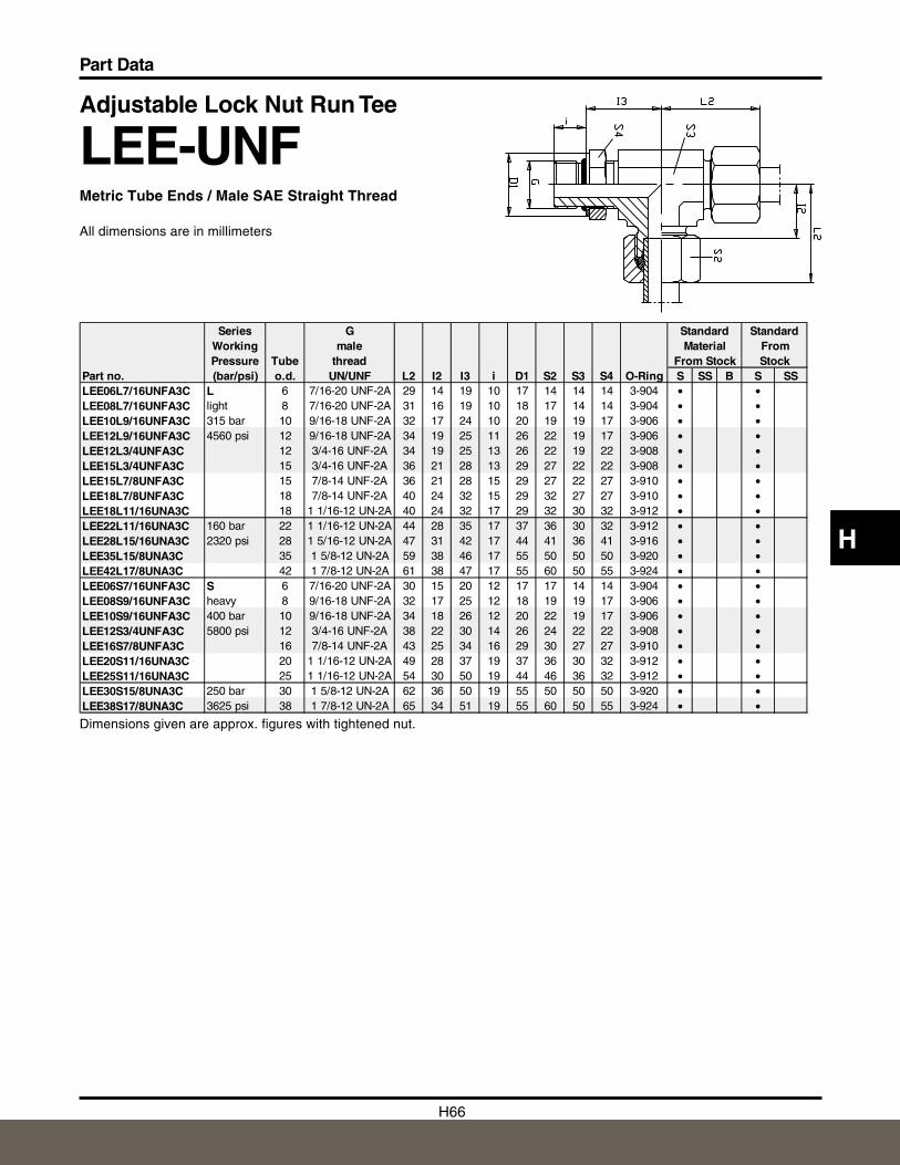
H66
Part Data
H
Adjustable Lock Nut Run Tee
LEE-UNFMetric Tube Ends / Male SAE Straight Thread
All dimensions are in millimeters
Dimensions given are approx. figures with tightened nut.
Series G Standard StandardWorking male Material FromPressure Tube thread From Stock Stock
Part no. (bar/psi) o.d. UN/UNF L2 I2 I3 i D1 S2 S3 S4 O-Ring S SS B S SSLEE06L7/16UNFA3C L 6 7/16-20 UNF-2A 29 14 19 10 17 14 14 14 3-904 • •LEE08L7/16UNFA3C light 8 7/16-20 UNF-2A 31 16 19 10 18 17 14 14 3-904 • •LEE10L9/16UNFA3C 315 bar 10 9/16-18 UNF-2A 32 17 24 10 20 19 19 17 3-906 • •LEE12L9/16UNFA3C 4560 psi 12 9/16-18 UNF-2A 34 19 25 11 26 22 19 17 3-906 • •LEE12L3/4UNFA3C 12 3/4-16 UNF-2A 34 19 25 13 26 22 19 22 3-908 • •LEE15L3/4UNFA3C 15 3/4-16 UNF-2A 36 21 28 13 29 27 22 22 3-908 • •LEE15L7/8UNFA3C 15 7/8-14 UNF-2A 36 21 28 15 29 27 22 27 3-910 • •LEE18L7/8UNFA3C 18 7/8-14 UNF-2A 40 24 32 15 29 32 27 27 3-910 • •LEE18L11/16UNA3C 18 1 1/16-12 UN-2A 40 24 32 17 29 32 30 32 3-912 • •LEE22L11/16UNA3C 160 bar 22 1 1/16-12 UN-2A 44 28 35 17 37 36 30 32 3-912 • •LEE28L15/16UNA3C 2320 psi 28 1 5/16-12 UN-2A 47 31 42 17 44 41 36 41 3-916 • •LEE35L15/8UNA3C 35 1 5/8-12 UN-2A 59 38 46 17 55 50 50 50 3-920 • •LEE42L17/8UNA3C 42 1 7/8-12 UN-2A 61 38 47 17 55 60 50 55 3-924 • •LEE06S7/16UNFA3C S 6 7/16-20 UNF-2A 30 15 20 12 17 17 14 14 3-904 • •LEE08S9/16UNFA3C heavy 8 9/16-18 UNF-2A 32 17 25 12 18 19 19 17 3-906 • •LEE10S9/16UNFA3C 400 bar 10 9/16-18 UNF-2A 34 18 26 12 20 22 19 17 3-906 • •LEE12S3/4UNFA3C 5800 psi 12 3/4-16 UNF-2A 38 22 30 14 26 24 22 22 3-908 • •LEE16S7/8UNFA3C 16 7/8-14 UNF-2A 43 25 34 16 29 30 27 27 3-910 • •LEE20S11/16UNA3C 20 1 1/16-12 UN-2A 49 28 37 19 37 36 30 32 3-912 • •LEE25S11/16UNA3C 25 1 1/16-12 UN-2A 54 30 50 19 44 46 36 32 3-912 • •LEE30S15/8UNA3C 250 bar 30 1 5/8-12 UN-2A 62 36 50 19 55 50 50 50 3-920 • •LEE38S17/8UNA3C 3625 psi 38 1 7/8-12 UN-2A 65 34 51 19 55 60 50 55 3-924 • •
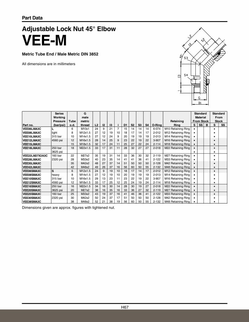
H67
Part Data
Adjustable Lock Nut 45° Elbow
VEE-MMetric Tube End / Male Metric DIN 3852
All dimensions are in millimeters
Dimensions given are approx. figures with tightened nut.
Series G Standard StandardWorking male Material FromPressure Tube metric Retaining From Stock Stock
Part no. (bar/psi) o.d. thread L2 I2 I3 i D1 S2 S3 S4 O-Ring Ring S SS B S SSVEE06LMA3C L 6 M10x1 24 9 21 7 15 14 14 14 6-074 M10 Retaining Ring • •VEE08LMA3C light 8 M12x1.5 27 12 19 10 18 17 14 17 2-012 M12 Retaining Ring • •VEE10LMA3C 315 bar 10 M14x1.5 27 12 24 9 20 19 19 19 2-013 M14 Retaining Ring • •VEE12LMA3C 4560 psi 12 M16x1.5 28 14 25 9 23 22 19 22 3-907 M16 Retaining Ring • •VEE15LMA3C 15 M18x1.5 32 17 24 11 25 27 22 24 2-114 M18 Retaining Ring • •VEE18LMA3C 250 bar 18 M22x1.5 33 17 31 11 28 32 27 27 2-018 M22 Retaining Ring • •
3625 psi • •VEE22LM27X2A3C 160 bar 22 M27x2 35 19 31 14 33 36 30 32 2-119 M27 Retaining Ring • •VEE28LMA3C 2320 psi 28 M33x2 40 23 35 14 41 41 36 41 2-122 M33 Retaining Ring • •VEE35LMA3C 35 M42x2 48 27 37 14 51 50 50 50 2-128 M42 Retaining Ring • •VEE42LMA3C 42 M48x2 49 26 37 16 56 60 50 55 2-132 M48 Retaining Ring • •VEE06SMA3C S 6 M12x1.5 24 9 19 10 18 17 14 17 2-012 M12 Retaining Ring • •VEE08SMA3C heavy 8 M14x1.5 27 12 19 10 20 19 19 19 2-013 M14 Retaining Ring • •VEE10SMA3C 315 bar 10 M16x1.5 29 13 23 11 23 22 19 22 3-907 M16 Retaining Ring • •VEE12SMA3C 4560 psi 12 M18x1.5 33 17 25 12 25 24 19 24 2-114 M18 Retaining Ring • •VEE16SMA3C 250 bar 16 M22x1.5 34 16 30 14 28 30 19 27 2-018 M22 Retaining Ring • •VEE20SMA3C 3625 psi 20 M27x2 38 16 35 16 33 36 27 32 2-119 M27 Retaining Ring • •VEE25SMA3C 160 bar 25 M33x2 43 19 37 16 41 46 36 41 2-122 M33 Retaining Ring • •VEE30SMA3C 2320 psi 30 M42x2 50 24 37 17 51 50 50 50 2-128 M42 Retaining Ring • •VEE38SMA3C 38 M48x2 52 21 38 19 56 60 50 55 2-132 M48 Retaining Ring • •
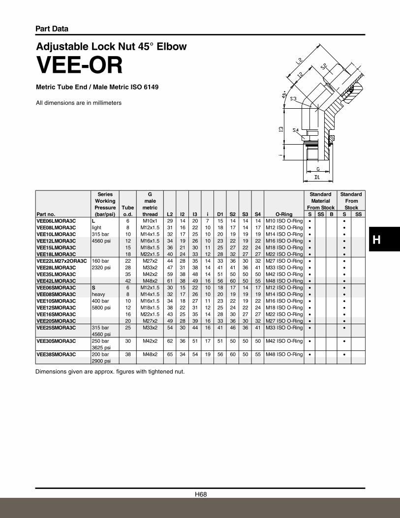
H68
Part Data
H
Adjustable Lock Nut 45° Elbow
VEE-ORMetric Tube End / Male Metric ISO 6149
All dimensions are in millimeters
Dimensions given are approx. figures with tightened nut.
Series G Standard StandardWorking male Material FromPressure Tube metric From Stock Stock
Part no. (bar/psi) o.d. thread L2 I2 I3 i D1 S2 S3 S4 O-Ring S SS B S SSVEE06LMORA3C L 6 M10x1 29 14 20 7 15 14 14 14 M10 ISO O-Ring • •VEE08LMORA3C light 8 M12x1.5 31 16 22 10 18 17 14 17 M12 ISO O-Ring • •VEE10LMORA3C 315 bar 10 M14x1.5 32 17 25 10 20 19 19 19 M14 ISO O-Ring • •VEE12LMORA3C 4560 psi 12 M16x1.5 34 19 26 10 23 22 19 22 M16 ISO O-Ring • •VEE15LMORA3C 15 M18x1.5 36 21 30 11 25 27 22 24 M18 ISO O-Ring • •VEE18LMORA3C 18 M22x1.5 40 24 33 12 28 32 27 27 M22 ISO O-Ring • •VEE22LM27x2ORA3C 160 bar 22 M27x2 44 28 35 14 33 36 30 32 M27 ISO O-Ring • •VEE28LMORA3C 2320 psi 28 M33x2 47 31 38 14 41 41 36 41 M33 ISO O-Ring • •VEE35LMORA3C 35 M42x2 59 38 48 14 51 50 50 50 M42 ISO O-Ring • •VEE42LMORA3C 42 M48x2 61 38 49 16 56 60 50 55 M48 ISO O-Ring • •VEE06SMORA3C S 6 M12x1.5 30 15 22 10 18 17 14 17 M12 ISO O-Ring • •VEE08SMORA3C heavy 8 M14x1.5 32 17 26 10 20 19 19 19 M14 ISO O-Ring • •VEE10SMORA3C 400 bar 10 M16x1.5 34 18 27 11 23 22 19 22 M16 ISO O-Ring • •VEE12SMORA3C 5800 psi 12 M18x1.5 38 22 31 12 25 24 22 24 M18 ISO O-Ring • •VEE16SMORA3C 16 M22x1.5 43 25 35 14 28 30 27 27 M22 ISO O-Ring • •VEE20SMORA3C 20 M27x2 49 28 39 16 33 36 30 32 M27 ISO O-Ring • •VEE25SMORA3C 315 bar 25 M33x2 54 30 44 16 41 46 36 41 M33 ISO O-Ring • •
4560 psiVEE30SMORA3C 250 bar 30 M42x2 62 36 51 17 51 50 50 50 M42 ISO O-Ring • •
3625 psiVEE38SMORA3C 200 bar 38 M48x2 65 34 54 19 56 60 50 55 M48 ISO O-Ring • •
2900 psi
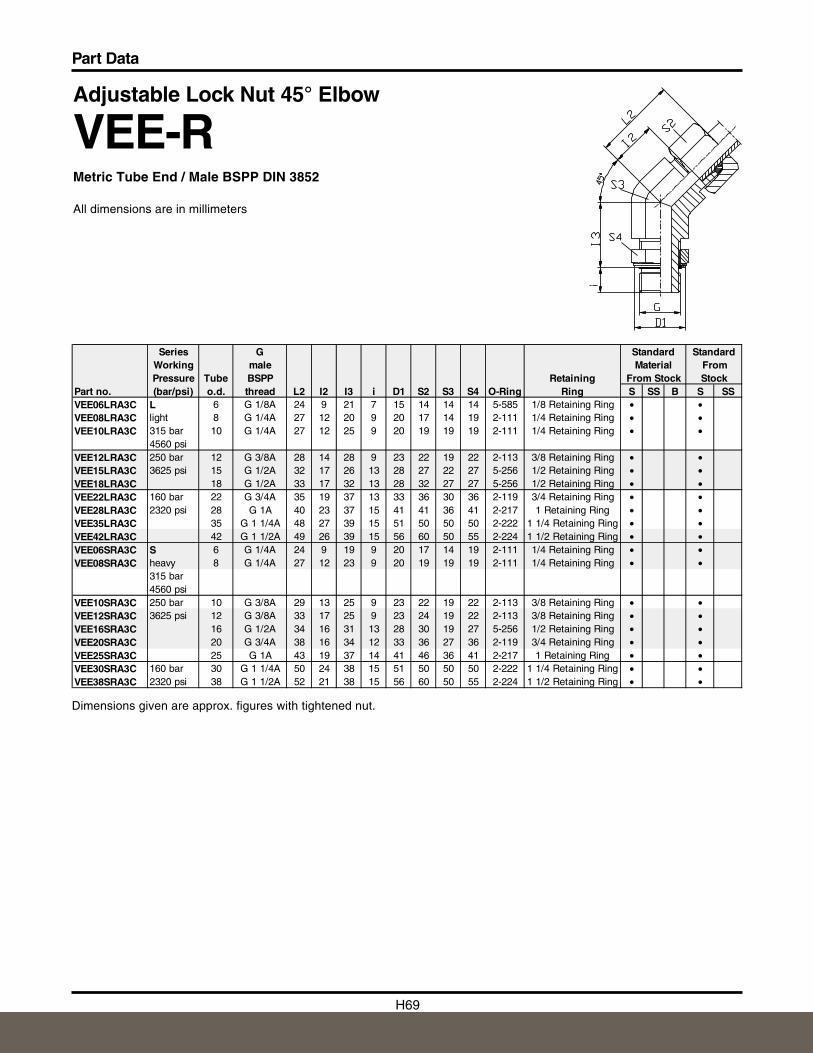
H69
Part Data
Adjustable Lock Nut 45° Elbow
VEE-RMetric Tube End / Male BSPP DIN 3852
All dimensions are in millimeters
Dimensions given are approx. figures with tightened nut.
Series G Standard StandardWorking male Material FromPressure Tube BSPP Retaining From Stock Stock
Part no. (bar/psi) o.d. thread L2 I2 I3 i D1 S2 S3 S4 O-Ring Ring S SS B S SSVEE06LRA3C L 6 G 1/8A 24 9 21 7 15 14 14 14 5-585 1/8 Retaining Ring • •VEE08LRA3C light 8 G 1/4A 27 12 20 9 20 17 14 19 2-111 1/4 Retaining Ring • •VEE10LRA3C 315 bar 10 G 1/4A 27 12 25 9 20 19 19 19 2-111 1/4 Retaining Ring • •
4560 psiVEE12LRA3C 250 bar 12 G 3/8A 28 14 28 9 23 22 19 22 2-113 3/8 Retaining Ring • •VEE15LRA3C 3625 psi 15 G 1/2A 32 17 26 13 28 27 22 27 5-256 1/2 Retaining Ring • •VEE18LRA3C 18 G 1/2A 33 17 32 13 28 32 27 27 5-256 1/2 Retaining Ring • •VEE22LRA3C 160 bar 22 G 3/4A 35 19 37 13 33 36 30 36 2-119 3/4 Retaining Ring • •VEE28LRA3C 2320 psi 28 G 1A 40 23 37 15 41 41 36 41 2-217 1 Retaining Ring • •VEE35LRA3C 35 G 1 1/4A 48 27 39 15 51 50 50 50 2-222 1 1/4 Retaining Ring • •VEE42LRA3C 42 G 1 1/2A 49 26 39 15 56 60 50 55 2-224 1 1/2 Retaining Ring • •VEE06SRA3C S 6 G 1/4A 24 9 19 9 20 17 14 19 2-111 1/4 Retaining Ring • •VEE08SRA3C heavy 8 G 1/4A 27 12 23 9 20 19 19 19 2-111 1/4 Retaining Ring • •
315 bar4560 psi
VEE10SRA3C 250 bar 10 G 3/8A 29 13 25 9 23 22 19 22 2-113 3/8 Retaining Ring • •VEE12SRA3C 3625 psi 12 G 3/8A 33 17 25 9 23 24 19 22 2-113 3/8 Retaining Ring • •VEE16SRA3C 16 G 1/2A 34 16 31 13 28 30 19 27 5-256 1/2 Retaining Ring • •VEE20SRA3C 20 G 3/4A 38 16 34 12 33 36 27 36 2-119 3/4 Retaining Ring • •VEE25SRA3C 25 G 1A 43 19 37 14 41 46 36 41 2-217 1 Retaining Ring • •VEE30SRA3C 160 bar 30 G 1 1/4A 50 24 38 15 51 50 50 50 2-222 1 1/4 Retaining Ring • •VEE38SRA3C 2320 psi 38 G 1 1/2A 52 21 38 15 56 60 50 55 2-224 1 1/2 Retaining Ring • •
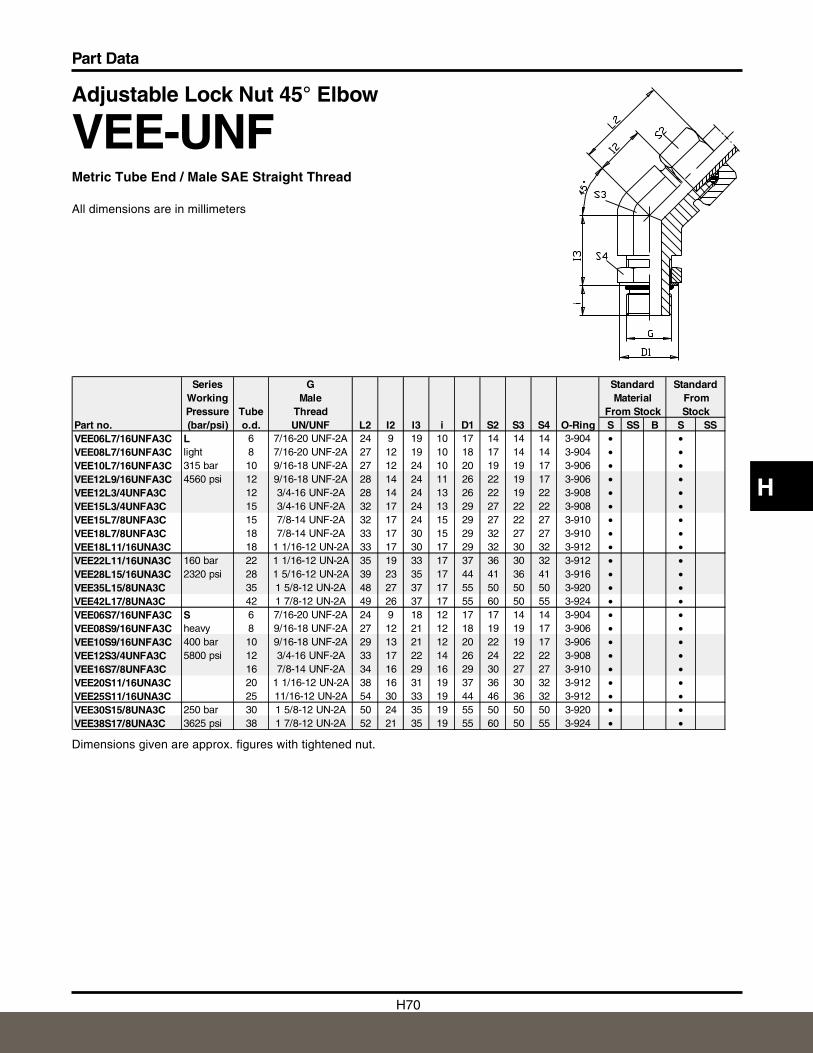
H70
Part Data
H
Adjustable Lock Nut 45° Elbow
VEE-UNFMetric Tube End / Male SAE Straight Thread
All dimensions are in millimeters
Dimensions given are approx. figures with tightened nut.
Series G Standard StandardWorking Male Material FromPressure Tube Thread From Stock Stock
Part no. (bar/psi) o.d. UN/UNF L2 I2 I3 i D1 S2 S3 S4 O-Ring S SS B S SSVEE06L7/16UNFA3C L 6 7/16-20 UNF-2A 24 9 19 10 17 14 14 14 3-904 • •VEE08L7/16UNFA3C light 8 7/16-20 UNF-2A 27 12 19 10 18 17 14 14 3-904 • •VEE10L7/16UNFA3C 315 bar 10 9/16-18 UNF-2A 27 12 24 10 20 19 19 17 3-906 • •VEE12L9/16UNFA3C 4560 psi 12 9/16-18 UNF-2A 28 14 24 11 26 22 19 17 3-906 • •VEE12L3/4UNFA3C 12 3/4-16 UNF-2A 28 14 24 13 26 22 19 22 3-908 • •VEE15L3/4UNFA3C 15 3/4-16 UNF-2A 32 17 24 13 29 27 22 22 3-908 • •VEE15L7/8UNFA3C 15 7/8-14 UNF-2A 32 17 24 15 29 27 22 27 3-910 • •VEE18L7/8UNFA3C 18 7/8-14 UNF-2A 33 17 30 15 29 32 27 27 3-910 • •VEE18L11/16UNA3C 18 1 1/16-12 UN-2A 33 17 30 17 29 32 30 32 3-912 • •VEE22L11/16UNA3C 160 bar 22 1 1/16-12 UN-2A 35 19 33 17 37 36 30 32 3-912 • •VEE28L15/16UNA3C 2320 psi 28 1 5/16-12 UN-2A 39 23 35 17 44 41 36 41 3-916 • •VEE35L15/8UNA3C 35 1 5/8-12 UN-2A 48 27 37 17 55 50 50 50 3-920 • •VEE42L17/8UNA3C 42 1 7/8-12 UN-2A 49 26 37 17 55 60 50 55 3-924 • •VEE06S7/16UNFA3C S 6 7/16-20 UNF-2A 24 9 18 12 17 17 14 14 3-904 • •VEE08S9/16UNFA3C heavy 8 9/16-18 UNF-2A 27 12 21 12 18 19 19 17 3-906 • •VEE10S9/16UNFA3C 400 bar 10 9/16-18 UNF-2A 29 13 21 12 20 22 19 17 3-906 • •VEE12S3/4UNFA3C 5800 psi 12 3/4-16 UNF-2A 33 17 22 14 26 24 22 22 3-908 • •VEE16S7/8UNFA3C 16 7/8-14 UNF-2A 34 16 29 16 29 30 27 27 3-910 • •VEE20S11/16UNA3C 20 1 1/16-12 UN-2A 38 16 31 19 37 36 30 32 3-912 • •VEE25S11/16UNA3C 25 11/16-12 UN-2A 54 30 33 19 44 46 36 32 3-912 • •VEE30S15/8UNA3C 250 bar 30 1 5/8-12 UN-2A 50 24 35 19 55 50 50 50 3-920 • •VEE38S17/8UNA3C 3625 psi 38 1 7/8-12 UN-2A 52 21 35 19 55 60 50 55 3-924 • •
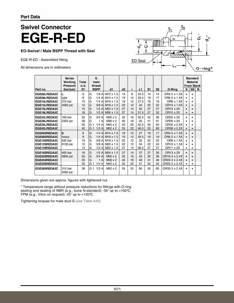
H71
Part Data
Swivel Connector
EGE-R-EDEO-Swivel / Male BSPP Thread with Seal
EGE-R-ED - Assembled fitting
All dimensions are in millimeters
Dimensions given are approx. figures with tightened nut.
* Temperature range without pressure reductions for fittings with O-ringsealing and sealing of NBR (e.g., buna N-standard) -35° up to +100°C,FPM (e.g., Viton on request) -25° up to +120°C.
Tightening torques for male stud G (see Table A43).
Series G StandardWorking Tube male MaterialPressure o.d. thread From Stock
Part no. (bar/psi) D1 BSPP d1 d2 i L1 S1 S2 O-Ring S SS B
EGE06LREDA3C L 6 G 1/8 A M12 x 1.5 14 8 24.5 14 14 OR4.5 x 1.5X • •EGE08LREDA3C light 8 G 1/4 A M14 x 1.5 19 12 29.5 19 17 OR6.5 x 1.5X • •EGE10LREDA3C 315 bar 10 G 1/4 A M16 x 1.5 19 12 27.5 19 19 OR8 x 1.5X • •EGE12LREDA3C 4560 psi 12 G 3/8 A M18 x 1.5 22 12 34 22 22 OR10 x 1.5X • •EGE15LREDA3C 15 G 1/2 A M22 x 1.5 27 14 32 27 27 OR12 x 2X • •EGE18LREDA3C 18 G 1/2 A M26 x 1.5 27 14 31.5 27 32 OR15 x 2X • •
EGE22LREDA3C 160 bar 22 G 3/4 A M30 x 2 32 16 32.5 32 36 OR20 x 2X • •EGE28LREDA3C 2320 psi 28 G 1 A M36 x 2 40 18 35 41 41 OR26 x 2X • •EGE35LREDA3C 35 G 1 1/4 A M45 x 2 50 20 42.5 50 50 OR32 x 2.5X • •EGE42LREDA3C 42 G 1 1/2 A M52 x 2 55 22 46.5 55 60 OR38 x 2.5X • •
EGE06SREDA3C S 6 G 1/4 A M14 x 1.5 19 12 27 19 17 OR4.5 x 1.5X • •EGE08SREDA3C heavy 8 G 1/4 A M16 x 1.5 19 12 29.5 19 19 OR6.5 x 1.5X • •EGE10SREDA3C 630 bar 10 G 3/8 A M18 x 1.5 22 12 32 22 22 OR8 x 1.5X • •EGE12SREDA3C 9130 psi 12 G 3/8 A M20 x 1.5 22 12 34 22 24 OR10 x 1.5X • •EGE14SREDA3C 14 G 1/2 A M22 x 1.5 27 14 36.5 27 27 OR11 x 2X • •
EGE16SREDA3C 400 bar 16 G 1/2 A M24 x 1.5 27 14 37 27 30 OR13 x 2X • •EGE20SREDA3C 5800 psi 20 G 3/4 A M30 x 2 32 16 43 32 36 OR16.3 x 2.4X • •EGE25SREDA3C 25 G 1 A M36 x 2 40 18 48 41 46 OR20.3 x 2.4X • •EGE30SREDA3C 30 G 1 1/4 A M42 x 2 50 20 51 50 50 OR25.3 x 2.4X • •
EGE38SREDA3C 315 bar 38 G 1 1/2 A M52 x 2 55 22 60 55 60 OR33.3 x 2.4X • •4560 psi
ED Seal
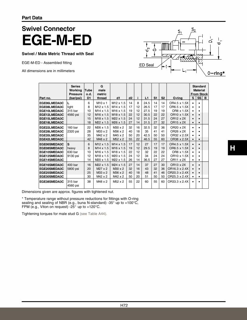
H72
Part Data
H
Swivel Connector
EGE-M-EDSwivel / Male Metric Thread with Seal
EGE-M-ED - Assembled fitting
All dimensions are in millimeters
Dimensions given are approx. figures with tightened nut.
* Temperature range without pressure reductions for fittings with O-ringsealing and sealing of NBR (e.g., buna N-standard) -35° up to +100°C,FPM (e.g., Viton on request) -25° up to +120°C.
Tightening torques for male stud G (see Table A44).
Series G StandardWorking Tube male MaterialPressure o.d. metric From Stock
Part no. (bar/psi) D1 thread d1 d2 i L1 S1 S2 O-ring S SS B
EGE06LMEDA3C L 6 M10 x 1 M12 x 1.5 14 8 24.5 14 14 OR4.5 x 1.5X • •EGE08LMEDA3C light 8 M12 x 1.5 M14 x 1.5 17 12 26.5 17 17 OR6.5 x 1.5X • •EGE10LMEDA3C 315 bar 10 M14 x 1.5 M16 x 1.5 19 12 27.5 19 19 OR8 x 1.5X • •EGE12LMEDA3C 4560 psi 12 M16 x 1.5 M18 x 1.5 22 12 30.5 22 22 OR10 x 1.5X • •EGE15LMEDA3C 15 M18 x 1.5 M22 x 1.5 24 12 31.5 24 27 OR12 x 2X • •EGE18LMEDA3C 18 M22 x 1.5 M26 x 1.5 27 14 31.5 27 32 OR15 x 2X • •
EGE22LMEDA3C 160 bar 22 M26 x 1.5 M30 x 2 32 16 32.5 32 36 OR20 x 2X • •EGE28LMEDA3C 2320 psi 28 M33 x 2 M36 x 2 40 18 35 41 41 OR26 x 2X • •EGE35LMEDA3C 35 M42 x 2 M45 x 2 50 20 42.5 50 50 OR32 x 2.5X • •EGE42LMEDA3C 42 M48 x 2 M52 x 2 55 22 46.5 55 60 OR38 x 2.5X • •
EGE06SMEDA3C S 6 M12 x 1.5 M14 x 1.5 17 12 27 17 17 OR4.5 x 1.5X • •EGE08SMEDA3C heavy 8 M14 x 1.5 M16 x 1.5 19 12 29.5 19 19 OR6.5 x 1.5X • •EGE10SMEDA3C 630 bar 10 M16 x 1.5 M18 x 1.5 22 12 32 22 22 OR8 x 1.5X • •EGE12SMEDA3C 9130 psi 12 M18 x 1.5 M20 x 1.5 24 12 34 24 24 OR10 x 1.5X • •EGE14SMEDA3C 14 M20 x 1.5 M22 x 1.5 26 14 36.5 27 27 OR11 x 2X • •
EGE16SMEDA3C 400 bar 16 M22 x 1.5 M24 x 1.5 27 14 37 27 30 OR13 x 2X • •EGE20SMEDA3C 5800 psi 20 M27 x 2 M30 x 2 32 16 43 32 36 OR16.3 x 2.4X • •EGE25SMEDA3C 25 M33 x 2 M36 x 2 40 18 48 41 46 OR20.3 x 2.4X • •EGE30SMEDA3C 30 M42 x 2 M42 x 2 50 20 51 50 50 OR25.3 x 2.4X • •
EGE38SMEDA3C 315 bar 38 M48 x 2 M52 x 2 55 22 60 55 60 OR33.3 x 2.4X • •4560 psi
ED Seal
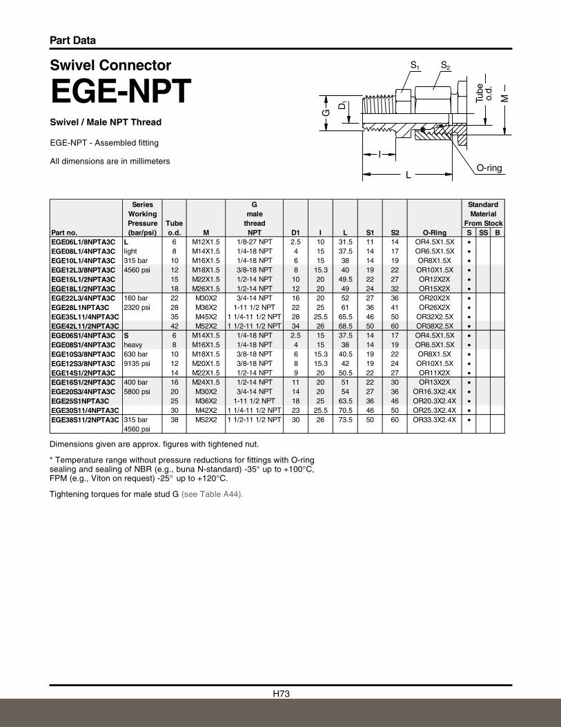
H73
Part Data
Swivel Connector
EGE-NPTSwivel / Male NPT Thread
EGE-NPT - Assembled fitting
All dimensions are in millimeters
Dimensions given are approx. figures with tightened nut.
* Temperature range without pressure reductions for fittings with O-ringsealing and sealing of NBR (e.g., buna N-standard) -35° up to +100°C,FPM (e.g., Viton on request) -25° up to +120°C.
Tightening torques for male stud G (see Table A44).
L
M
G
I
S1
D1
O-ring
Tube
o.d.
2S
M
Series G StandardWorking male MaterialPressure Tube thread From Stock
Part no. (bar/psi) o.d. M NPT D1 I L S1 S2 O-Ring S SS BEGE06L1/8NPTA3C L 6 M12X1.5 1/8-27 NPT 2.5 10 31.5 11 14 OR4.5X1.5X •EGE08L1/4NPTA3C light 8 M14X1.5 1/4-18 NPT 4 15 37.5 14 17 OR6.5X1.5X •EGE10L1/4NPTA3C 315 bar 10 M16X1.5 1/4-18 NPT 6 15 38 14 19 OR8X1.5X •EGE12L3/8NPTA3C 4560 psi 12 M18X1.5 3/8-18 NPT 8 15.3 40 19 22 OR10X1.5X •EGE15L1/2NPTA3C 15 M22X1.5 1/2-14 NPT 10 20 49.5 22 27 OR12X2X •EGE18L1/2NPTA3C 18 M26X1.5 1/2-14 NPT 12 20 49 24 32 OR15X2X •EGE22L3/4NPTA3C 160 bar 22 M30X2 3/4-14 NPT 16 20 52 27 36 OR20X2X •EGE28L1NPTA3C 2320 psi 28 M36X2 1-11 1/2 NPT 22 25 61 36 41 OR26X2X •EGE35L11/4NPTA3C 35 M45X2 1 1/4-11 1/2 NPT 28 25.5 65.5 46 50 OR32X2.5X •EGE42L11/2NPTA3C 42 M52X2 1 1/2-11 1/2 NPT 34 26 68.5 50 60 OR38X2.5X •EGE06S1/4NPTA3C S 6 M14X1.5 1/4-18 NPT 2.5 15 37.5 14 17 OR4.5X1.5X •EGE08S1/4NPTA3C heavy 8 M16X1.5 1/4-18 NPT 4 15 38 14 19 OR6.5X1.5X •EGE10S3/8NPTA3C 630 bar 10 M18X1.5 3/8-18 NPT 6 15.3 40.5 19 22 OR8X1.5X •EGE12S3/8NPTA3C 9135 psi 12 M20X1.5 3/8-18 NPT 8 15.3 42 19 24 OR10X1.5X •EGE14S1/2NPTA3C 14 M22X1.5 1/2-14 NPT 9 20 50.5 22 27 OR11X2X •EGE16S1/2NPTA3C 400 bar 16 M24X1.5 1/2-14 NPT 11 20 51 22 30 OR13X2X •EGE20S3/4NPTA3C 5800 psi 20 M30X2 3/4-14 NPT 14 20 54 27 36 OR16.3X2.4X •EGE25S1NPTA3C 25 M36X2 1-11 1/2 NPT 18 25 63.5 36 46 OR20.3X2.4X •EGE30S11/4NPTA3C 30 M42X2 1 1/4-11 1/2 NPT 23 25.5 70.5 46 50 OR25.3X2.4X •EGE38S11/2NPTA3C 315 bar 38 M52X2 1 1/2-11 1/2 NPT 30 26 73.5 50 60 OR33.3X2.4X •
4560 psi
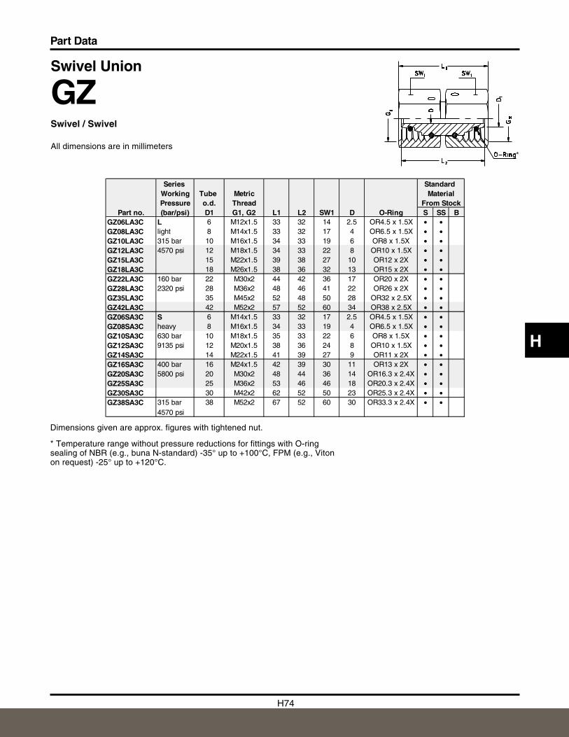
H74
Part Data
H
Swivel Union
GZSwivel / Swivel
All dimensions are in millimeters
Dimensions given are approx. figures with tightened nut.
* Temperature range without pressure reductions for fittings with O-ringsealing of NBR (e.g., buna N-standard) -35° up to +100°C, FPM (e.g., Vitonon request) -25° up to +120°C.
*
Series Standard Working Tube Metric MaterialPressure o.d. Thread From Stock
Part no. (bar/psi) D1 G1, G2 L1 L2 SW1 D O-Ring S SS BGZ06LA3C L 6 M12x1.5 33 32 14 2.5 OR4.5 x 1.5X • •GZ08LA3C light 8 M14x1.5 33 32 17 4 OR6.5 x 1.5X • •GZ10LA3C 315 bar 10 M16x1.5 34 33 19 6 OR8 x 1.5X • •GZ12LA3C 4570 psi 12 M18x1.5 34 33 22 8 OR10 x 1.5X • •GZ15LA3C 15 M22x1.5 39 38 27 10 OR12 x 2X • •GZ18LA3C 18 M26x1.5 38 36 32 13 OR15 x 2X • •GZ22LA3C 160 bar 22 M30x2 44 42 36 17 OR20 x 2X • •GZ28LA3C 2320 psi 28 M36x2 48 46 41 22 OR26 x 2X • •GZ35LA3C 35 M45x2 52 48 50 28 OR32 x 2.5X • •GZ42LA3C 42 M52x2 57 52 60 34 OR38 x 2.5X • •GZ06SA3C S 6 M14x1.5 33 32 17 2.5 OR4.5 x 1.5X • •GZ08SA3C heavy 8 M16x1.5 34 33 19 4 OR6.5 x 1.5X • •GZ10SA3C 630 bar 10 M18x1.5 35 33 22 6 OR8 x 1.5X • •GZ12SA3C 9135 psi 12 M20x1.5 38 36 24 8 OR10 x 1.5X • •GZ14SA3C 14 M22x1.5 41 39 27 9 OR11 x 2X • •GZ16SA3C 400 bar 16 M24x1.5 42 39 30 11 OR13 x 2X • •GZ20SA3C 5800 psi 20 M30x2 48 44 36 14 OR16.3 x 2.4X • •GZ25SA3C 25 M36x2 53 46 46 18 OR20.3 x 2.4X • •GZ30SA3C 30 M42x2 62 52 50 23 OR25.3 x 2.4X • •GZ38SA3C 315 bar 38 M52x2 67 52 60 30 OR33.3 x 2.4X • •
4570 psi
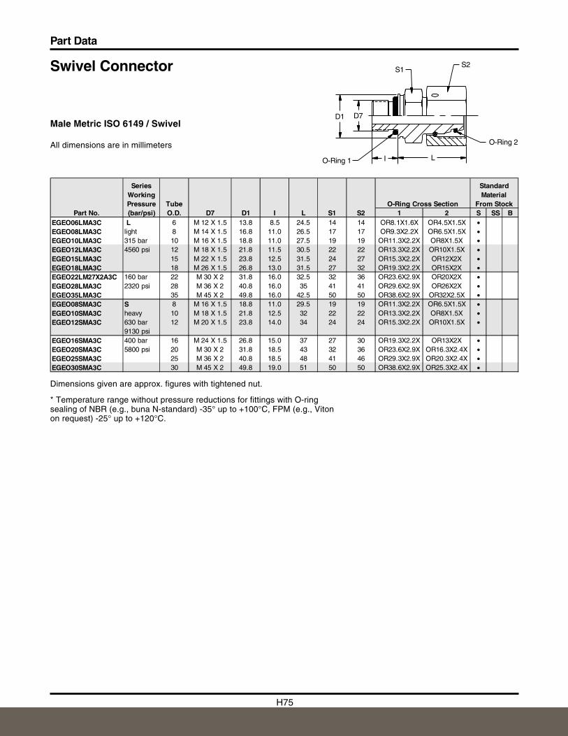
H75
Part Data
Swivel Connector
Male Metric ISO 6149 / Swivel
All dimensions are in millimeters
S1S2
D1 D7
O-Ring 1
O-Ring 2
I L
Dimensions given are approx. figures with tightened nut.
* Temperature range without pressure reductions for fittings with O-ringsealing of NBR (e.g., buna N-standard) -35° up to +100°C, FPM (e.g., Vitonon request) -25° up to +120°C.
D7 D1 I L S1 S2 1 2 S SS BEGEO06LMA3C L 6 M 12 X 1.5 13.8 8.5 24.5 14 14 OR8.1X1.6X OR4.5X1.5X •EGEO08LMA3C light 8 M 14 X 1.5 16.8 11.0 26.5 17 17 OR9.3X2.2X OR6.5X1.5X •EGEO10LMA3C 315 bar 10 M 16 X 1.5 18.8 11.0 27.5 19 19 OR11.3X2.2X OR8X1.5X •EGEO12LMA3C 4560 psi 12 M 18 X 1.5 21.8 11.5 30.5 22 22 OR13.3X2.2X OR10X1.5X •EGEO15LMA3C 15 M 22 X 1.5 23.8 12.5 31.5 24 27 OR15.3X2.2X OR12X2X •EGEO18LMA3C 18 M 26 X 1.5 26.8 13.0 31.5 27 32 OR19.3X2.2X OR15X2X •EGEO22LM27X2A3C 160 bar 22 M 30 X 2 31.8 16.0 32.5 32 36 OR23.6X2.9X OR20X2X •EGEO28LMA3C 2320 psi 28 M 36 X 2 40.8 16.0 35 41 41 OR29.6X2.9X OR26X2X •EGEO35LMA3C 35 M 45 X 2 49.8 16.0 42.5 50 50 OR38.6X2.9X OR32X2.5X •EGEO08SMA3C S 8 M 16 X 1.5 18.8 11.0 29.5 19 19 OR11.3X2.2X OR6.5X1.5X •EGEO10SMA3C heavy 10 M 18 X 1.5 21.8 12.5 32 22 22 OR13.3X2.2X OR8X1.5X •EGEO12SMA3C 630 bar
9130 psi12 M 20 X 1.5 23.8 14.0 34 24 24 OR15.3X2.2X OR10X1.5X •
EGEO16SMA3C 400 bar 16 M 24 X 1.5 26.8 15.0 37 27 30 OR19.3X2.2X OR13X2X •EGEO20SMA3C 5800 psi 20 M 30 X 2 31.8 18.5 43 32 36 OR23.6X2.9X OR16.3X2.4X •EGEO25SMA3C 25 M 36 X 2 40.8 18.5 48 41 46 OR29.3X2.9X OR20.3X2.4X •EGEO30SMA3C 30 M 45 X 2 49.8 19.0 51 50 50 OR38.6X2.9X OR25.3X2.4X •
Standard Material
From StockPart No.
Series Working Pressure (bar/psi)
TubeO.D.
O-Ring Cross Section
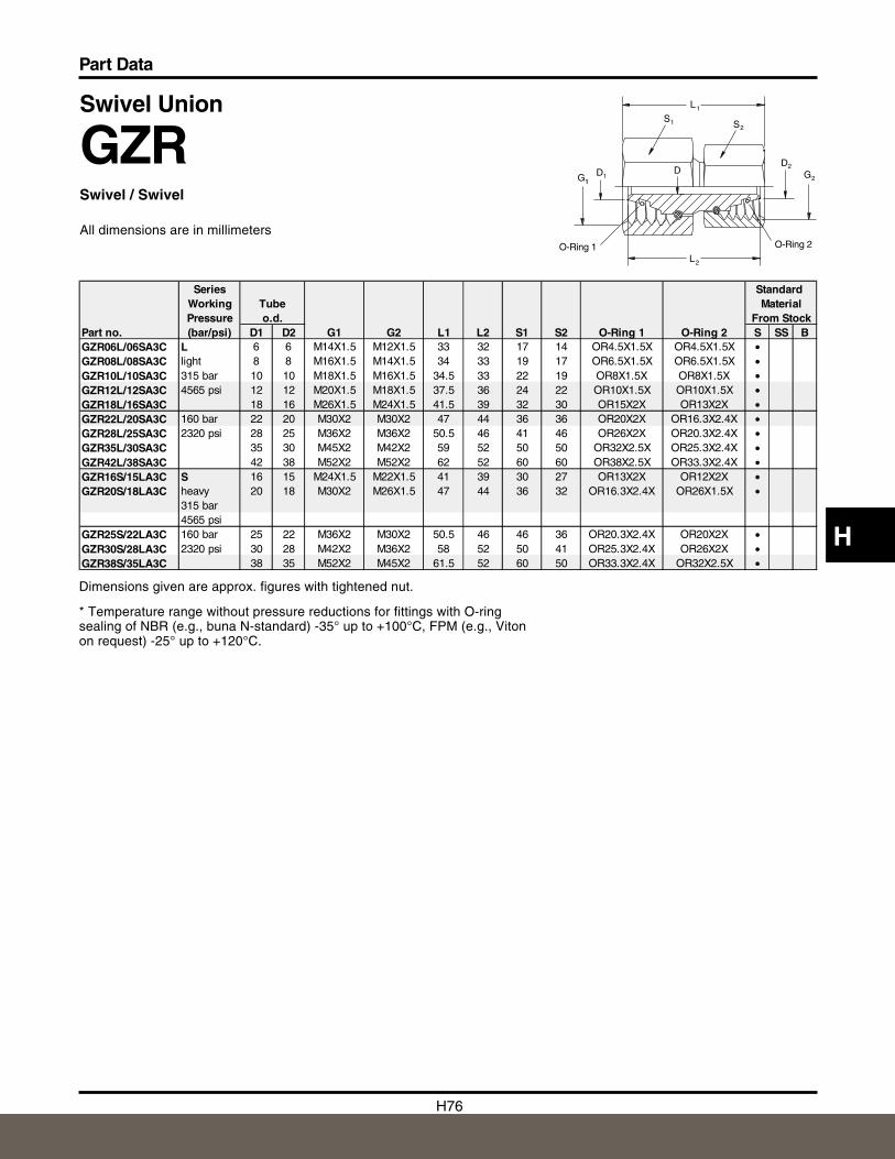
H76
Part Data
H
Swivel Union
GZRSwivel / Swivel
All dimensions are in millimeters
Dimensions given are approx. figures with tightened nut.
* Temperature range without pressure reductions for fittings with O-ringsealing of NBR (e.g., buna N-standard) -35° up to +100°C, FPM (e.g., Vitonon request) -25° up to +120°C.
O-Ring 1L2
DG
S1
1D1
L1
S2
D2
G2
O-Ring 2
Series Standard Working Tube MaterialPressure o.d. From Stock
Part no. (bar/psi) D1 D2 G1 G2 L1 L2 S1 S2 O-Ring 1 O-Ring 2 S SS BGZR06L/06SA3C L 6 6 M14X1.5 M12X1.5 33 32 17 14 OR4.5X1.5X OR4.5X1.5X •GZR08L/08SA3C light 8 8 M16X1.5 M14X1.5 34 33 19 17 OR6.5X1.5X OR6.5X1.5X •GZR10L/10SA3C 315 bar 10 10 M18X1.5 M16X1.5 34.5 33 22 19 OR8X1.5X OR8X1.5X •GZR12L/12SA3C 4565 psi 12 12 M20X1.5 M18X1.5 37.5 36 24 22 OR10X1.5X OR10X1.5X •GZR18L/16SA3C 18 16 M26X1.5 M24X1.5 41.5 39 32 30 OR15X2X OR13X2X •GZR22L/20SA3C 160 bar 22 20 M30X2 M30X2 47 44 36 36 OR20X2X OR16.3X2.4X •GZR28L/25SA3C 2320 psi 28 25 M36X2 M36X2 50.5 46 41 46 OR26X2X OR20.3X2.4X •GZR35L/30SA3C 35 30 M45X2 M42X2 59 52 50 50 OR32X2.5X OR25.3X2.4X •GZR42L/38SA3C 42 38 M52X2 M52X2 62 52 60 60 OR38X2.5X OR33.3X2.4X •GZR16S/15LA3C S 16 15 M24X1.5 M22X1.5 41 39 30 27 OR13X2X OR12X2X •GZR20S/18LA3C heavy 20 18 M30X2 M26X1.5 47 44 36 32 OR16.3X2.4X OR26X1.5X •
315 bar4565 psi
GZR25S/22LA3C 160 bar 25 22 M36X2 M30X2 50.5 46 46 36 OR20.3X2.4X OR20X2X •GZR30S/28LA3C 2320 psi 30 28 M42X2 M36X2 58 52 50 41 OR25.3X2.4X OR26X2X •GZR38S/35LA3C 38 35 M52X2 M45X2 61.5 52 60 50 OR33.3X2.4X OR32X2.5X •
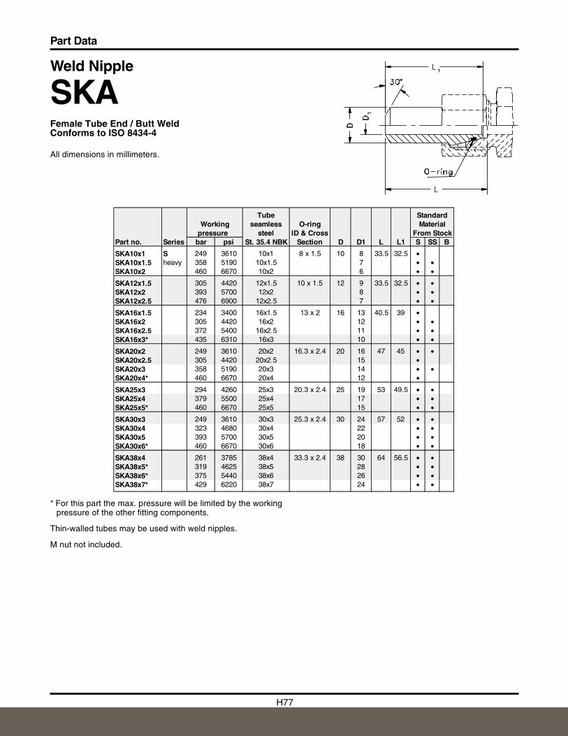
H77
Part Data
Weld Nipple
SKAFemale Tube End / Butt WeldConforms to ISO 8434-4
All dimensions in millimeters.
* For this part the max. pressure will be limited by the workingpressure of the other fitting components.
Thin-walled tubes may be used with weld nipples.
M nut not included.
Tube StandardWorking seamless O-ring Material
pressure steel ID & Cross From StockPart no. Series bar psi St. 35.4 NBK Section D D1 L L1 S SS B
SKA10x1 S 249 3610 10x1 8 x 1.5 10 8 33.5 32.5 •SKA10x1.5 heavy 358 5190 10x1.5 7 • •SKA10x2 460 6670 10x2 6 • •
SKA12x1.5 305 4420 12x1.5 10 x 1.5 12 9 33.5 32.5 • •SKA12x2 393 5700 12x2 8 • •SKA12x2.5 476 6900 12x2.5 7 • •
SKA16x1.5 234 3400 16x1.5 13 x 2 16 13 40.5 39 •SKA16x2 305 4420 16x2 12 • •SKA16x2.5 372 5400 16x2.5 11 • •SKA16x3* 435 6310 16x3 10 • •
SKA20x2 249 3610 20x2 16.3 x 2.4 20 16 47 45 • •SKA20x2.5 305 4420 20x2.5 15 •SKA20x3 358 5190 20x3 14 • •SKA20x4* 460 6670 20x4 12 •
SKA25x3 294 4260 25x3 20.3 x 2.4 25 19 53 49.5 • •SKA25x4 379 5500 25x4 17 • •SKA25x5* 460 6670 25x5 15 • •
SKA30x3 249 3610 30x3 25.3 x 2.4 30 24 57 52 • •SKA30x4 323 4680 30x4 22 • •SKA30x5 393 5700 30x5 20 • •SKA30x6* 460 6670 30x6 18 • •
SKA38x4 261 3785 38x4 33.3 x 2.4 38 30 64 56.5 • •SKA38x5* 319 4625 38x5 28 • •SKA38x6* 375 5440 38x6 26 • •SKA38x7* 429 6220 38x7 24 • •
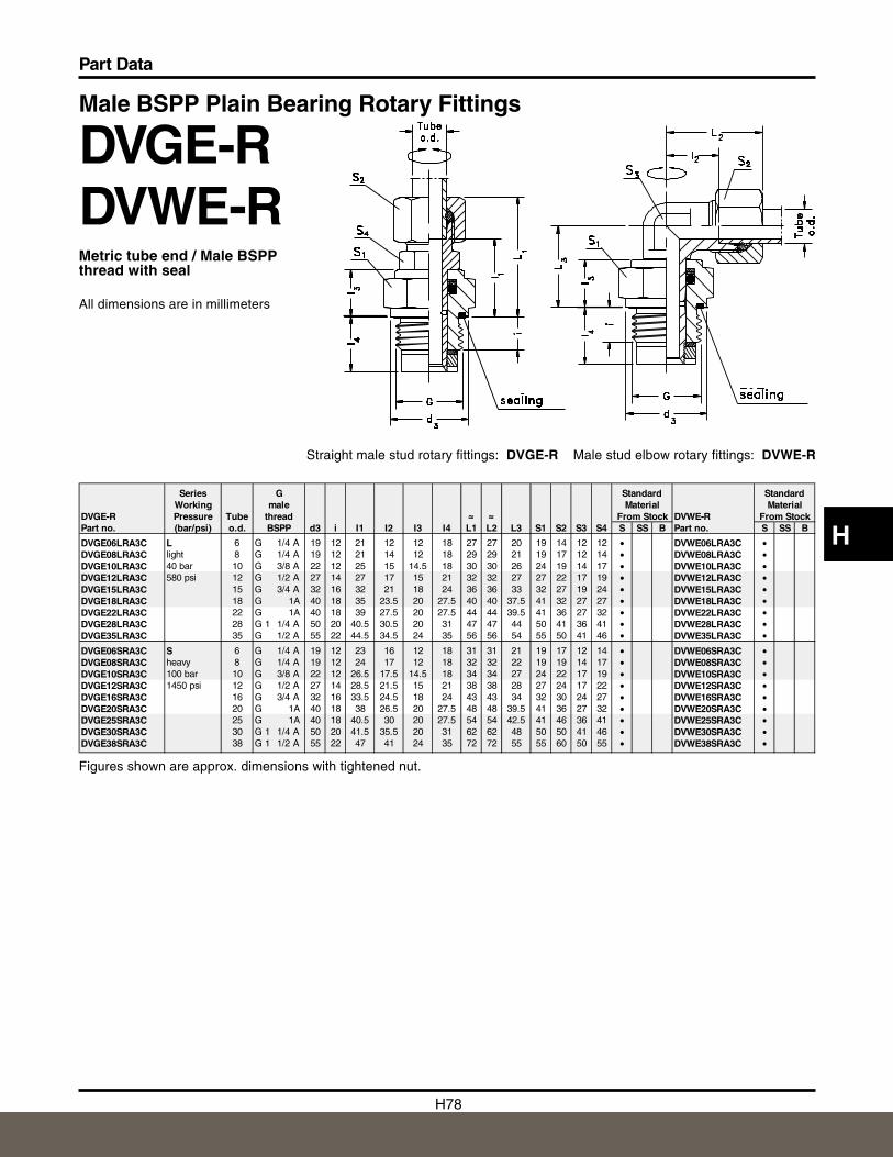
H78
Part Data
H
Straight male stud rotary fittings: DVGE-R Male stud elbow rotary fittings: DVWE-R
Male BSPP Plain Bearing Rotary Fittings
DVGE-RDVWE-RMetric tube end / Male BSPPthread with seal
All dimensions are in millimeters
Figures shown are approx. dimensions with tightened nut.
Series G Standard StandardWorking male Material Material
DVGE-R Pressure Tube thread ≈≈≈ ≈≈≈ From Stock DVWE-R From StockPart no. (bar/psi) o.d. BSPP d3 i I1 I2 I3 I4 L1 L2 L3 S1 S2 S3 S4 S SS B Part no. S SS B
DVGE06LRA3C L 6 G 1/4 A 19 12 21 12 12 18 27 27 20 19 14 12 12 • DVWE06LRA3C •DVGE08LRA3C light 8 G 1/4 A 19 12 21 14 12 18 29 29 21 19 17 12 14 • DVWE08LRA3C •DVGE10LRA3C 40 bar 10 G 3/8 A 22 12 25 15 14.5 18 30 30 26 24 19 14 17 • DVWE10LRA3C •DVGE12LRA3C 580 psi 12 G 1/2 A 27 14 27 17 15 21 32 32 27 27 22 17 19 • DVWE12LRA3C •DVGE15LRA3C 15 G 3/4 A 32 16 32 21 18 24 36 36 33 32 27 19 24 • DVWE15LRA3C •DVGE18LRA3C 18 G 1A 40 18 35 23.5 20 27.5 40 40 37.5 41 32 27 27 • DVWE18LRA3C •DVGE22LRA3C 22 G 1A 40 18 39 27.5 20 27.5 44 44 39.5 41 36 27 32 • DVWE22LRA3C •DVGE28LRA3C 28 G 1 1/4 A 50 20 40.5 30.5 20 31 47 47 44 50 41 36 41 • DVWE28LRA3C •DVGE35LRA3C 35 G 1/2 A 55 22 44.5 34.5 24 35 56 56 54 55 50 41 46 • DVWE35LRA3C •
DVGE06SRA3C S 6 G 1/4 A 19 12 23 16 12 18 31 31 21 19 17 12 14 • DVWE06SRA3C •DVGE08SRA3C heavy 8 G 1/4 A 19 12 24 17 12 18 32 32 22 19 19 14 17 • DVWE08SRA3C •DVGE10SRA3C 100 bar 10 G 3/8 A 22 12 26.5 17.5 14.5 18 34 34 27 24 22 17 19 • DVWE10SRA3C •DVGE12SRA3C 1450 psi 12 G 1/2 A 27 14 28.5 21.5 15 21 38 38 28 27 24 17 22 • DVWE12SRA3C •DVGE16SRA3C 16 G 3/4 A 32 16 33.5 24.5 18 24 43 43 34 32 30 24 27 • DVWE16SRA3C •DVGE20SRA3C 20 G 1A 40 18 38 26.5 20 27.5 48 48 39.5 41 36 27 32 • DVWE20SRA3C •DVGE25SRA3C 25 G 1A 40 18 40.5 30 20 27.5 54 54 42.5 41 46 36 41 • DVWE25SRA3C •DVGE30SRA3C 30 G 1 1/4 A 50 20 41.5 35.5 20 31 62 62 48 50 50 41 46 • DVWE30SRA3C •DVGE38SRA3C 38 G 1 1/2 A 55 22 47 41 24 35 72 72 55 55 60 50 55 • DVWE38SRA3C •
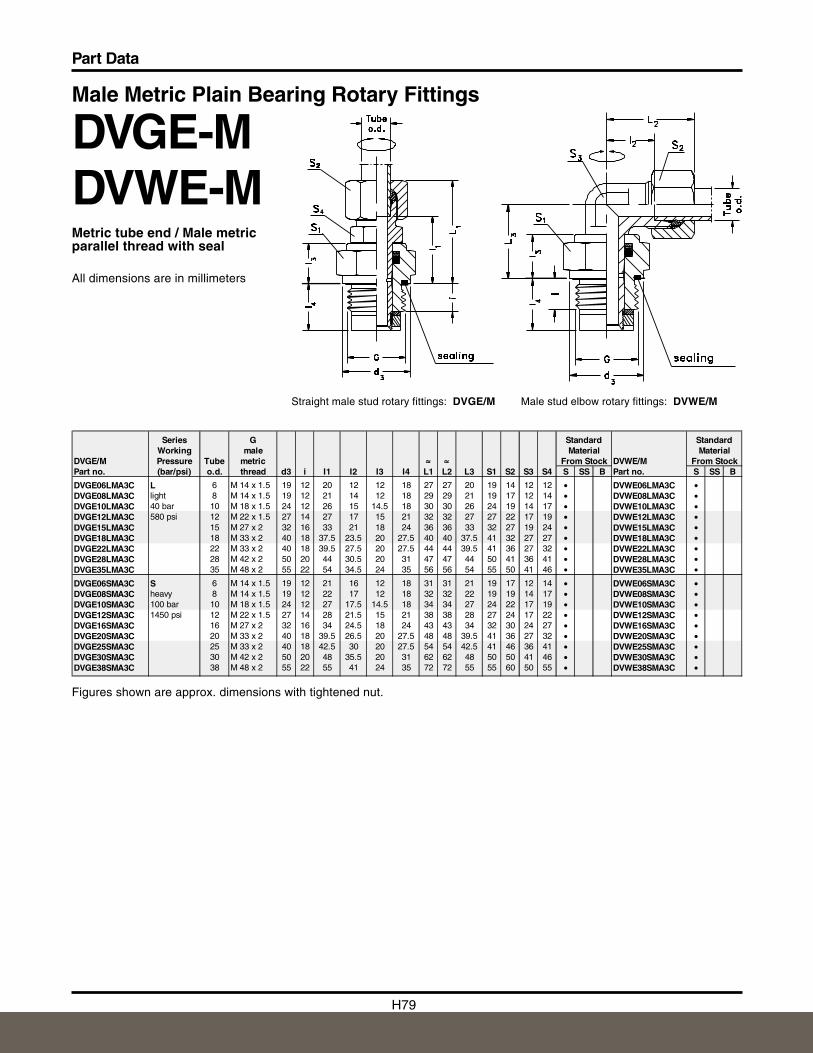
H79
Part Data
Male stud elbow rotary fittings: DVWE/MStraight male stud rotary fittings: DVGE/M
Male Metric Plain Bearing Rotary Fittings
DVGE-MDVWE-MMetric tube end / Male metricparallel thread with seal
All dimensions are in millimeters
Figures shown are approx. dimensions with tightened nut.
Series G Standard StandardWorking male Material Material
DVGE/M Pressure Tube metric ≈≈≈ ≈≈≈ From Stock DVWE/M From StockPart no. (bar/psi) o.d. thread d3 i I1 I2 I3 I4 L1 L2 L3 S1 S2 S3 S4 S SS B Part no. S SS B
DVGE06LMA3C L 6 M 14 x 1.5 19 12 20 12 12 18 27 27 20 19 14 12 12 • DVWE06LMA3C •DVGE08LMA3C light 8 M 14 x 1.5 19 12 21 14 12 18 29 29 21 19 17 12 14 • DVWE08LMA3C •DVGE10LMA3C 40 bar 10 M 18 x 1.5 24 12 26 15 14.5 18 30 30 26 24 19 14 17 • DVWE10LMA3C •DVGE12LMA3C 580 psi 12 M 22 x 1.5 27 14 27 17 15 21 32 32 27 27 22 17 19 • DVWE12LMA3C •DVGE15LMA3C 15 M 27 x 2 32 16 33 21 18 24 36 36 33 32 27 19 24 • DVWE15LMA3C •DVGE18LMA3C 18 M 33 x 2 40 18 37.5 23.5 20 27.5 40 40 37.5 41 32 27 27 • DVWE18LMA3C •DVGE22LMA3C 22 M 33 x 2 40 18 39.5 27.5 20 27.5 44 44 39.5 41 36 27 32 • DVWE22LMA3C •DVGE28LMA3C 28 M 42 x 2 50 20 44 30.5 20 31 47 47 44 50 41 36 41 • DVWE28LMA3C •DVGE35LMA3C 35 M 48 x 2 55 22 54 34.5 24 35 56 56 54 55 50 41 46 • DVWE35LMA3C •
DVGE06SMA3C S 6 M 14 x 1.5 19 12 21 16 12 18 31 31 21 19 17 12 14 • DVWE06SMA3C •DVGE08SMA3C heavy 8 M 14 x 1.5 19 12 22 17 12 18 32 32 22 19 19 14 17 • DVWE08SMA3C •DVGE10SMA3C 100 bar 10 M 18 x 1.5 24 12 27 17.5 14.5 18 34 34 27 24 22 17 19 • DVWE10SMA3C •DVGE12SMA3C 1450 psi 12 M 22 x 1.5 27 14 28 21.5 15 21 38 38 28 27 24 17 22 • DVWE12SMA3C •DVGE16SMA3C 16 M 27 x 2 32 16 34 24.5 18 24 43 43 34 32 30 24 27 • DVWE16SMA3C •DVGE20SMA3C 20 M 33 x 2 40 18 39.5 26.5 20 27.5 48 48 39.5 41 36 27 32 • DVWE20SMA3C •DVGE25SMA3C 25 M 33 x 2 40 18 42.5 30 20 27.5 54 54 42.5 41 46 36 41 • DVWE25SMA3C •DVGE30SMA3C 30 M 42 x 2 50 20 48 35.5 20 31 62 62 48 50 50 41 46 • DVWE30SMA3C •DVGE38SMA3C 38 M 48 x 2 55 22 55 41 24 35 72 72 55 55 60 50 55 • DVWE38SMA3C •
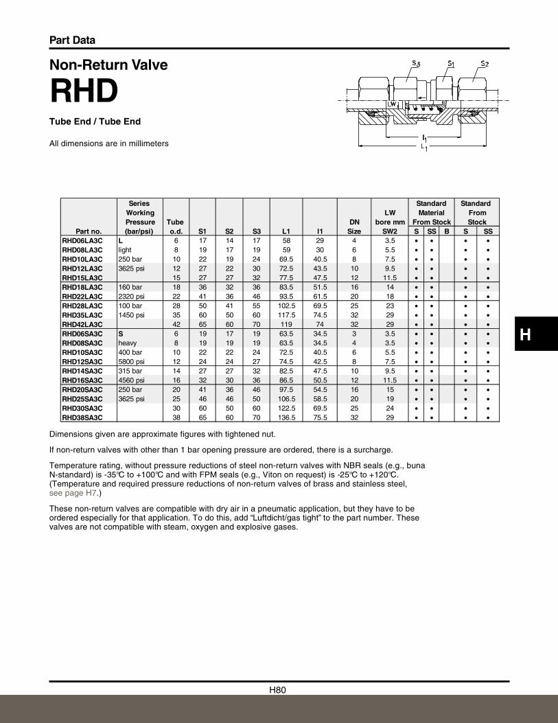
H80
Part Data
H
Non-Return Valve
RHDTube End / Tube End
All dimensions are in millimeters
Dimensions given are approximate figures with tightened nut.
If non-return valves with other than 1 bar opening pressure are ordered, there is a surcharge.
Temperature rating, without pressure reductions of steel non-return valves with NBR seals (e.g., bunaN-standard) is -35°C to +100°C and with FPM seals (e.g., Viton on request) is -25°C to +120°C.(Temperature and required pressure reductions of non-return valves of brass and stainless steel,see page H7.)
These non-return valves are compatible with dry air in a pneumatic application, but they have to beordered especially for that application. To do this, add “Luftdicht/gas tight” to the part number. Thesevalves are not compatible with steam, oxygen and explosive gases.
Series Standard Standard Working LW Material FromPressure Tube DN bore mm From Stock Stock
Part no. (bar/psi) o.d. S1 S2 S3 L1 l1 Size SW2 S SS B S SSRHD06LA3C L 6 17 14 17 58 29 4 3.5 • • • •RHD08LA3C light 8 19 17 19 59 30 6 5.5 • • • •RHD10LA3C 250 bar 10 22 19 24 69.5 40.5 8 7.5 • • • •RHD12LA3C 3625 psi 12 27 22 30 72.5 43.5 10 9.5 • • • •RHD15LA3C 15 27 27 32 77.5 47.5 12 11.5 • • • •RHD18LA3C 160 bar 18 36 32 36 83.5 51.5 16 14 • • • •RHD22LA3C 2320 psi 22 41 36 46 93.5 61.5 20 18 • • • •RHD28LA3C 100 bar 28 50 41 55 102.5 69.5 25 23 • • • •RHD35LA3C 1450 psi 35 60 50 60 117.5 74.5 32 29 • • • •RHD42LA3C 42 65 60 70 119 74 32 29 • • • •RHD06SA3C S 6 19 17 19 63.5 34.5 3 3.5 • • • •RHD08SA3C heavy 8 19 19 19 63.5 34.5 4 3.5 • • • •RHD10SA3C 400 bar 10 22 22 24 72.5 40.5 6 5.5 • • • •RHD12SA3C 5800 psi 12 24 24 27 74.5 42.5 8 7.5 • • • •RHD14SA3C 315 bar 14 27 27 32 82.5 47.5 10 9.5 • • • •RHD16SA3C 4560 psi 16 32 30 36 86.5 50.5 12 11.5 • • • •RHD20SA3C 250 bar 20 41 36 46 97.5 54.5 16 15 • • • •RHD25SA3C 3625 psi 25 46 46 50 106.5 58.5 20 19 • • • •RHD30SA3C 30 60 50 60 122.5 69.5 25 24 • • • •RHD38SA3C 38 65 60 70 136.5 75.5 32 29 • • • •
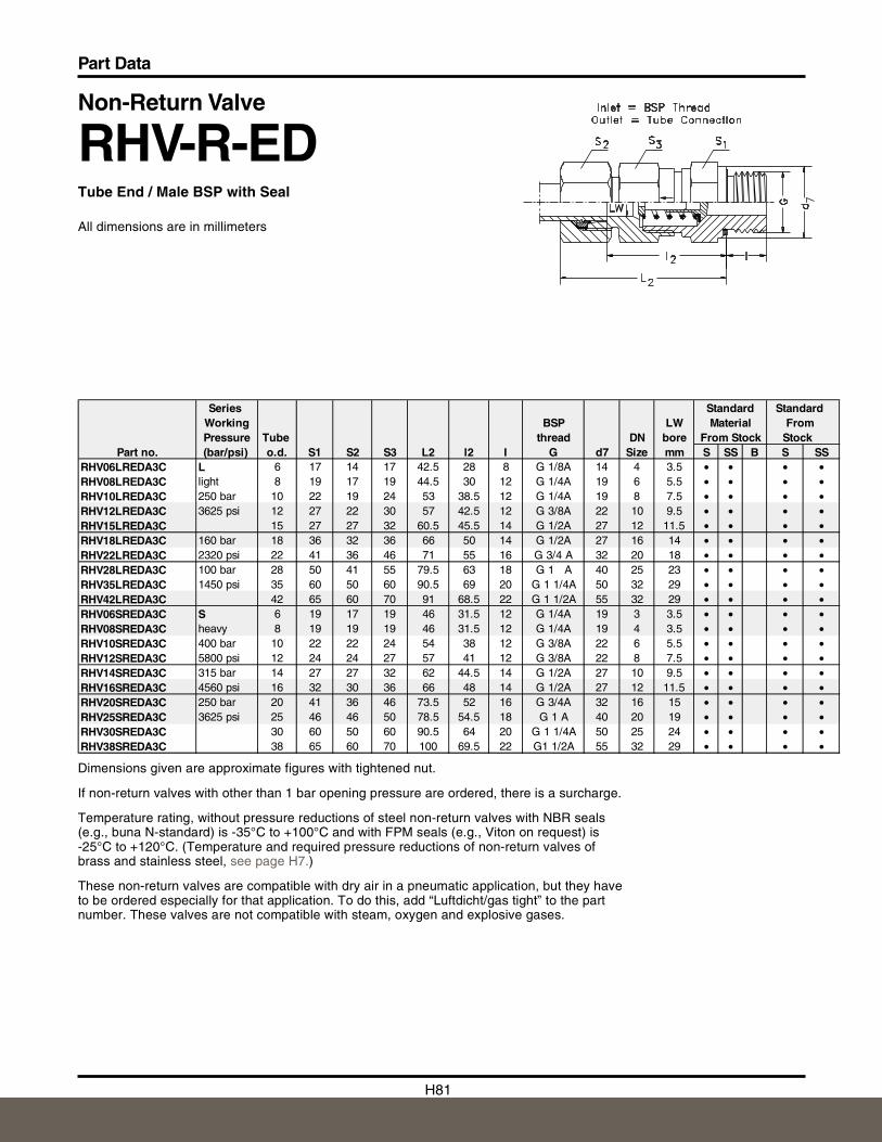
H81
Part Data
Non-Return Valve
RHV-R-EDTube End / Male BSP with Seal
All dimensions are in millimeters
Dimensions given are approximate figures with tightened nut.
If non-return valves with other than 1 bar opening pressure are ordered, there is a surcharge.
Temperature rating, without pressure reductions of steel non-return valves with NBR seals(e.g., buna N-standard) is -35° C to +100°C and with FPM seals (e.g., Viton on request) is-25°C to +120°C. (Temperature and required pressure reductions of non-return valves ofbrass and stainless steel, see page H7.)
These non-return valves are compatible with dry air in a pneumatic application, but they haveto be ordered especially for that application. To do this, add “Luftdicht/gas tight” to the partnumber. These valves are not compatible with steam, oxygen and explosive gases.
Series Standard StandardWorking BSP LW Material FromPressure Tube thread DN bore From Stock Stock
Part no. (bar/psi) o.d. S1 S2 S3 L2 l2 I G d7 Size mm S SS B S SSRHV06LREDA3C L 6 17 14 17 42.5 28 8 G 1/8A 14 4 3.5 • • • •RHV08LREDA3C light 8 19 17 19 44.5 30 12 G 1/4A 19 6 5.5 • • • •RHV10LREDA3C 250 bar 10 22 19 24 53 38.5 12 G 1/4A 19 8 7.5 • • • •RHV12LREDA3C 3625 psi 12 27 22 30 57 42.5 12 G 3/8A 22 10 9.5 • • • •RHV15LREDA3C 15 27 27 32 60.5 45.5 14 G 1/2A 27 12 11.5 • • • •RHV18LREDA3C 160 bar 18 36 32 36 66 50 14 G 1/2A 27 16 14 • • • •RHV22LREDA3C 2320 psi 22 41 36 46 71 55 16 G 3/4 A 32 20 18 • • • •RHV28LREDA3C 100 bar 28 50 41 55 79.5 63 18 G 1 A 40 25 23 • • • •RHV35LREDA3C 1450 psi 35 60 50 60 90.5 69 20 G 1 1/4A 50 32 29 • • • •RHV42LREDA3C 42 65 60 70 91 68.5 22 G 1 1/2A 55 32 29 • • • •RHV06SREDA3C S 6 19 17 19 46 31.5 12 G 1/4A 19 3 3.5 • • • •RHV08SREDA3C heavy 8 19 19 19 46 31.5 12 G 1/4A 19 4 3.5 • • • •RHV10SREDA3C 400 bar 10 22 22 24 54 38 12 G 3/8A 22 6 5.5 • • • •RHV12SREDA3C 5800 psi 12 24 24 27 57 41 12 G 3/8A 22 8 7.5 • • • •RHV14SREDA3C 315 bar 14 27 27 32 62 44.5 14 G 1/2A 27 10 9.5 • • • •RHV16SREDA3C 4560 psi 16 32 30 36 66 48 14 G 1/2A 27 12 11.5 • • • •RHV20SREDA3C 250 bar 20 41 36 46 73.5 52 16 G 3/4A 32 16 15 • • • •RHV25SREDA3C 3625 psi 25 46 46 50 78.5 54.5 18 G 1 A 40 20 19 • • • •RHV30SREDA3C 30 60 50 60 90.5 64 20 G 1 1/4A 50 25 24 • • • •RHV38SREDA3C 38 65 60 70 100 69.5 22 G1 1/2A 55 32 29 • • • •
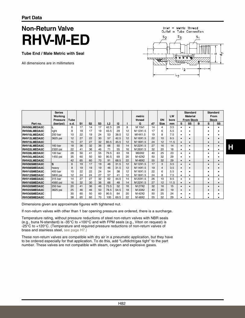
H82
Part Data
H
Non-Return Valve
RHV-M-EDTube End / Male Metric with Seal
All dimensions are in millimeters
Dimensions given are approximate figures with tightened nut.
If non-return valves with other than 1 bar opening pressure are ordered, there is a surcharge.
Temperature rating, without pressure reductions of steel non-return valves with NBR seals(e.g., buna N-standard) is -35° C to +100°C and with FPM seals (e.g., Viton on request) is-25°C to +120°C. (Temperature and required pressure reductions of non-return valves ofbrass and stainless steel, see page H7.)
These non-return valves are compatible with dry air in a pneumatic application, but they haveto be ordered especially for that application. To do this, add “Luftdicht/gas tight” to the partnumber. These valves are not compatible with steam, oxygen and explosive gases.
Series Standard StandardWorking metric LW Material FromPressure Tube thread DN bore From Stock Stock
Part no. (bar/psi) o.d. S1 S2 S3 L2 l2 I G d7 Size mm S SS B S SSRHV06LMEDA3C L 6 17 14 17 42.5 28 8 M 10x1 14 4 3.5 • • • •RHV08LMEDA3C light 8 19 17 19 43.5 29 12 M 12X1.5 17 6 5.5 • • • •RHV10LMEDA3C 250 bar 10 22 19 24 53 38.5 12 M14X1.5 19 8 7.5 • • • •RHV12LMEDA3C 3625 psi 12 27 22 30 57 42.5 12 M 16X1.5 22 10 9.5 • • • •RHV15LMEDA3C 15 27 27 32 60.5 45.5 12 M 18X1.5 24 12 11.5 • • • •RHV18LMEDA3C 160 bar 18 36 32 36 66 50 14 M 22X1.5 27 16 14 • • • •RHV22LMEDA3C 2320 psi 22 41 36 46 71 55 16 M 26X1.5 32 20 18 • • • •RHV28LMEDA3C 100 bar 28 50 41 55 79.5 63 18 M33X2 40 25 23 • • • •RHV35LMEDA3C 1450 psi 35 60 50 60 90.5 69 20 M 42X2 50 32 29 • • • •RHV42LMEDA3C 42 65 60 70 91 68.5 22 M 48X2 55 32 29 • • • •RHV06SMEDA3C S 6 19 17 19 46 31.5 12 M 12X1.5 17 3 3.5 • • • •RHV08SMEDA3C heavy 8 19 19 19 46 31.5 12 M 14X1.5 19 4 3.5 • • • •RHV10SMEDA3C 400 bar 10 22 22 24 54 38 12 M 16X1.5 22 6 5.5 • • • •RHV12SMEDA3C 5800 psi 12 24 24 27 57 41 12 M 18X1.5 24 8 7.5 • • • •RHV14SMEDA3C 315 bar 14 27 27 32 62 44.5 14 M 20X1.5 26 10 9.5 • • • •RHV16SMEDA3C 4560 psi 16 32 30 36 66 48 14 M 22X1.5 27 12 11.5 • • • •RHV20SMEDA3C 250 bar 20 41 36 46 73.5 52 16 M 27X2 32 16 15 • • • •RHV25SMEDA3C 3625 psi 25 46 46 50 78.5 54.5 18 M 33X2 40 20 19 • • • •RHV30SMEDA3C 30 60 50 60 90.5 64 20 M 42X2 50 25 24 • • • •RHV38SMEDA3C 38 65 60 70 100 69.5 22 M 48X2 55 32 29 • • • •
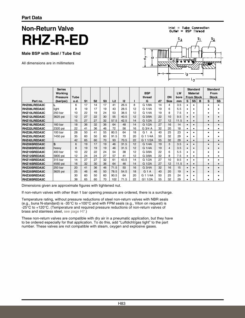
H83
Part Data
Non-Return Valve
RHZ-R-EDMale BSP with Seal / Tube End
All dimensions are in millimeters
Dimensions given are approximate figures with tightened nut.
If non-return valves with other than 1 bar opening pressure are ordered, there is a surcharge.
Temperature rating, without pressure reductions of steel non-return valves with NBR seals(e.g., buna N-standard) is -35° C to +100°C and with FPM seals (e.g., Viton on request) is-25°C to +120°C. (Temperature and required pressure reductions of non-return valves ofbrass and stainless steel, see page H7.)
These non-return valves are compatible with dry air in a pneumatic application, but they haveto be ordered especially for that application. To do this, add “Luftdicht/gas tight” to the partnumber. These valves are not compatible with steam, oxygen and explosive gases.
Series Standard StandardWorking BSP LW Material FromPressure Tube thread DN bore From Stock Stock
Part no. (bar/psi) o.d. S1 S2 S3 L2 l2 I G d7 Size mm S SS B S SSRHZ06LREDA3C L 6 17 14 17 41 26.5 8 G 1/8A 14 4 3.5 • • • •RHZ08LREDA3C light 8 19 17 19 43 28.5 12 G 1/4A 19 6 5.5 • • • •RHZ10LREDA3C 250 bar 10 22 19 24 53 38.5 12 G 1/4A 19 8 7.5 • • • •RHZ12LREDA3C 3625 psi 12 27 22 30 55 40.5 12 G 3/8A 22 10 9.5 • • • •RHZ15LREDA3C 15 27 27 32 57.5 42.5 14 G 1/2A 27 12 11.5 • • • •RHZ18LREDA3C 160 bar 18 36 32 36 64 48 14 G 1/2A 27 16 14 • • • •RHZ22LREDA3C 2320 psi 22 41 36 46 72 56 16 G 3/4 A 32 20 18 • • • •RHZ28LREDA3C 100 bar 28 50 41 55 80.5 64 18 G 1 A 40 25 23 • • • •RHZ35LREDA3C 1450 psi 35 60 50 60 91.5 70 20 G 1 1/4A 50 32 29 • • • •RHZ42LREDA3C 42 65 60 70 93 70.5 22 G 1 1/2A 55 32 29 • • • •RHZ06SREDA3C S 6 19 17 19 46 31.5 12 G 1/4A 19 3 3.5 • • • •RHZ08SREDA3C heavy 8 19 19 19 46 31.5 12 G 1/4A 19 4 3.5 • • • •RHZ10SREDA3C 400 bar 10 22 22 24 54 38 12 G 3/8A 22 6 5.5 • • • •RHZ12SREDA3C 5800 psi 12 24 24 27 57 41 12 G 3/8A 22 8 7.5 • • • •RHZ14SREDA3C 315 bar 14 27 27 32 61 43.5 14 G 1/2A 27 10 9.5 • • • •RHZ16SREDA3C 4560 psi 16 32 30 36 64 46 14 G 1/2A 27 12 11.5 • • • •RHZ20SREDA3C 250 bar 20 41 36 46 71.5 50 16 G 3/4A 32 16 15 • • • •RHZ25SREDA3C 3625 psi 25 46 46 50 78.5 54.5 18 G 1 A 40 20 19 • • • •RHZ30SREDA3C 30 60 50 60 90.5 64 20 G 1 1/4A 50 25 24 • • • •RHZ38SREDA3C 38 65 60 70 102 71.5 22 G1 1/2A 55 32 29 • • • •
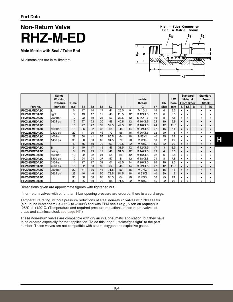
H84
Part Data
H
Non-Return Valve
RHZ-M-EDMale Metric with Seal / Tube End
All dimensions are in millimeters
Dimensions given are approximate figures with tightened nut.
If non-return valves with other than 1 bar opening pressure are ordered, there is a surcharge.
Temperature rating, without pressure reductions of steel non-return valves with NBR seals(e.g., buna N-standard) is -35° C to +100°C and with FPM seals (e.g., Viton on request) is-25°C to +120°C. (Temperature and required pressure reductions of non-return valves ofbrass and stainless steel, see page H7.)
These non-return valves are compatible with dry air in a pneumatic application, but they haveto be ordered especially for that application. To do this, add “Luftdicht/gas tight” to the partnumber. These valves are not compatible with steam, oxygen and explosive gases.
Series Standard Standard Working metric LW Material FromPressure Tube thread DN bore From Stock Stock
Part no. (bar/psi) o.d. S1 S2 S3 L2 l2 I G d7 Size mm S SS B S SSRHZ06LMEDA3C L 6 17 14 17 41 26.5 8 M 10x1 14 4 3.5 • • • •RHZ08LMEDA3C light 8 19 17 19 43 28.5 12 M 12X1.5 17 6 5.5 • • • •RHZ10LMEDA3C 250 bar 10 22 19 24 53 38.5 12 M14X1.5 19 8 7.5 • • • •RHZ12LMEDA3C 3625 psi 12 27 22 30 55 40.5 12 M 16X1.5 22 10 9.5 • • • •RHZ15LMEDA3C 15 27 27 32 57.5 42.5 12 M 18X1.5 24 12 11.5 • • • •RHZ18LMEDA3C 160 bar 18 36 32 36 64 48 14 M 22X1.5 27 16 14 • • • •RHZ22LMEDA3C 2320 psi 22 41 36 46 72 56 16 M 26X1.5 32 20 18 • • • •RHZ28LMEDA3C 100 bar 28 50 41 55 80.5 64 18 M33X2 40 25 23 • • • •RHZ35LMEDA3C 1450 psi 35 60 50 60 91.5 70 20 M 42X2 50 32 29 • • • •RHZ42LMEDA3C 42 65 60 70 93 70.5 22 M 48X2 55 32 29 • • • •RHZ06SMEDA3C S 6 19 17 19 46 31.5 12 M 12X1.5 17 3 3.5 • • • •RHZ08SMEDA3C heavy 8 19 19 19 46 31.5 12 M 14X1.5 19 4 3.5 • • • •RHZ10SMEDA3C 400 bar 10 22 22 24 54 38 12 M 16X1.5 22 6 5.5 • • • •RHZ12SMEDA3C 5800 psi 12 24 24 27 57 41 12 M 18X1.5 24 8 7.5 • • • •RHZ14SMEDA3C 315 bar 14 27 27 32 61 43.5 14 M 20X1.5 26 10 9.5 • • • •RHZ16SMEDA3C 4560 psi 16 32 30 36 64 46 14 M 22X1.5 27 12 11.5 • • • •RHZ20SMEDA3C 250 bar 20 41 36 46 71.5 50 16 M 27X2 32 16 15 • • • •RHZ25SMEDA3C 3625 psi 25 46 46 50 78.5 54.5 18 M 33X2 40 20 19 • • • •RHZ30SMEDA3C 30 60 50 60 90.5 64 20 M 42X2 50 25 24 • • • •RHZ38SMEDA3C 38 65 60 70 102 71.5 22 M 48X2 55 32 29 • • • •
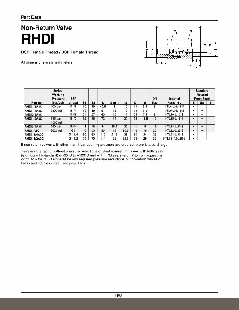
H85
Part Data
Non-Return Valve
RHDIBSP Female Thread / BSP Female Thread
All dimensions are in millimeters
If non-return valves with other than 1 bar opening pressure are ordered, there is a surcharge.
Temperature rating, without pressure reductions of steel non-return valves with NBR seals(e.g., buna N-standard) is -35° C to +100°C and with FPM seals (e.g., Viton on request) is-25°C to +120°C. (Temperature and required pressure reductions of non-return valves ofbrass and stainless steel, see page H7.)
Series StandardWorking MaterialPressure BSP DN Internal From Stock
Part no. (bar/psi) thread S1 S3 L t1 min. t2 D d Size Parts I-TL S SS BRHDI1/8A3C 400 bar G1/8 19 19 42.5 8 12 19 3.5 3 I-TL6-L/6u.8-S •RHDI1/4A3C 5800 psi G1/4 19 19 51 12 16 19 3.5 4 I-TL6-L/6u.8-S • •RHDI3/8A3C G3/8 24 27 60 12 17 24 7.5 8 I-TL10-L/12-S • •RHDI1/2A3C 315 bar G1/2 32 36 72 15 20 32 11.5 12 I-TL15-L/16-S • •
4560 psiRHDI3/4A3C 250 bar G3/4 41 46 84 16.5 22 41 15 16 I-TL18-L/20-S • •RHDI1A3C 3625 psi G1 46 50 95 19 25.5 46 19 20 I-TL22-L/25-S • •RHDI11/4A3C G1 1/4 60 60 110 21.5 28 60 24 25 I-TL28-L/30-S •RHDI11/2A3C G1 1/2 65 70 114 22 28.5 65 29 32 I-TL35+42-L38-S •
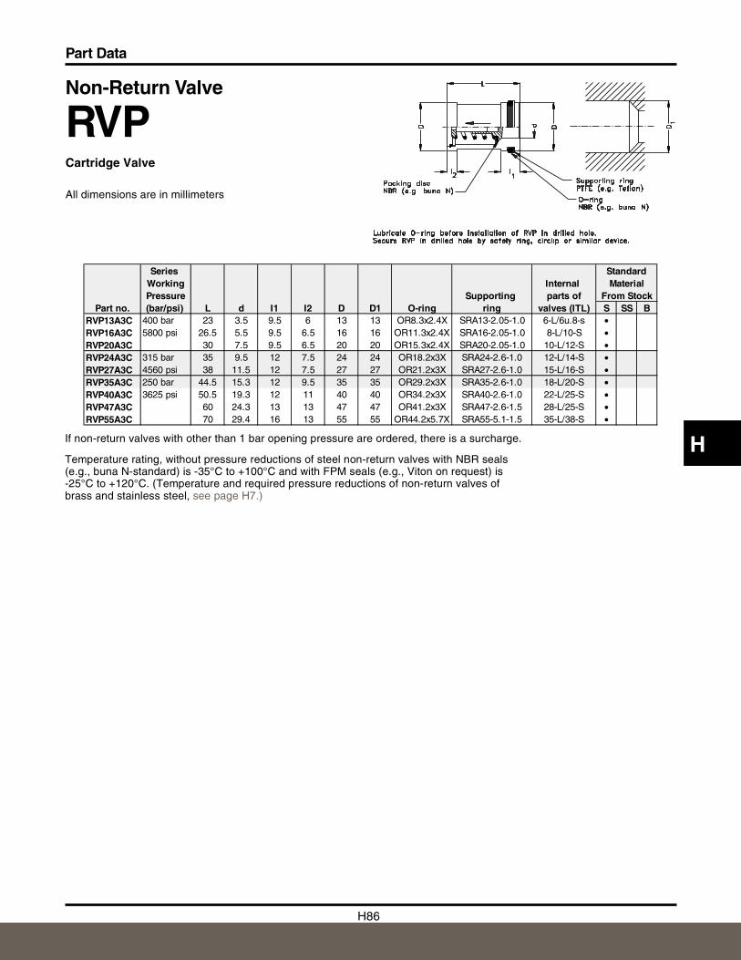
H86
Part Data
H
Non-Return Valve
RVPCartridge Valve
All dimensions are in millimeters
If non-return valves with other than 1 bar opening pressure are ordered, there is a surcharge.
Temperature rating, without pressure reductions of steel non-return valves with NBR seals(e.g., buna N-standard) is -35° C to +100°C and with FPM seals (e.g., Viton on request) is-25°C to +120°C. (Temperature and required pressure reductions of non-return valves ofbrass and stainless steel, see page H7.)
Series StandardWorking Internal MaterialPressure Supporting parts of From Stock
Part no. (bar/psi) L d I1 I2 D D1 O-ring ring valves (ITL) S SS BRVP13A3C 400 bar 23 3.5 9.5 6 13 13 OR8.3x2.4X SRA13-2.05-1.0 6-L/6u.8-s •RVP16A3C 5800 psi 26.5 5.5 9.5 6.5 16 16 OR11.3x2.4X SRA16-2.05-1.0 8-L/10-S •RVP20A3C 30 7.5 9.5 6.5 20 20 OR15.3x2.4X SRA20-2.05-1.0 10-L/12-S •RVP24A3C 315 bar 35 9.5 12 7.5 24 24 OR18.2x3X SRA24-2.6-1.0 12-L/14-S •RVP27A3C 4560 psi 38 11.5 12 7.5 27 27 OR21.2x3X SRA27-2.6-1.0 15-L/16-S •RVP35A3C 250 bar 44.5 15.3 12 9.5 35 35 OR29.2x3X SRA35-2.6-1.0 18-L/20-S •RVP40A3C 3625 psi 50.5 19.3 12 11 40 40 OR34.2x3X SRA40-2.6-1.0 22-L/25-S •RVP47A3C 60 24.3 13 13 47 47 OR41.2x3X SRA47-2.6-1.5 28-L/25-S •RVP55A3C 70 29.4 16 13 55 55 OR44.2x5.7X SRA55-5.1-1.5 35-L/38-S •
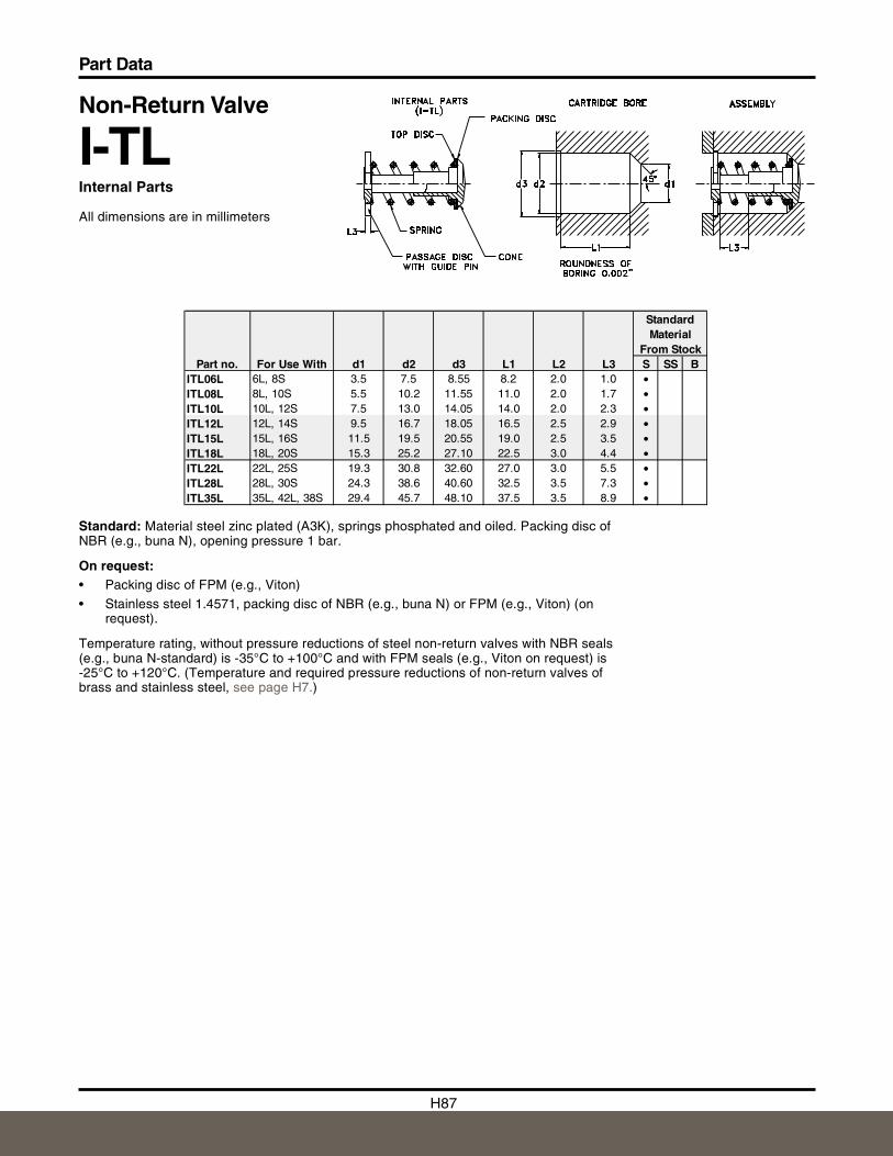
H87
Part Data
Non-Return Valve
I-TLInternal Parts
All dimensions are in millimeters
Standard: Material steel zinc plated (A3K), springs phosphated and oiled. Packing disc ofNBR (e.g., buna N), opening pressure 1 bar.
On request:• Packing disc of FPM (e.g., Viton)
• Stainless steel 1.4571, packing disc of NBR (e.g., buna N) or FPM (e.g., Viton) (onrequest).
Temperature rating, without pressure reductions of steel non-return valves with NBR seals(e.g., buna N-standard) is -35° C to +100°C and with FPM seals (e.g., Viton on request) is-25°C to +120°C. (Temperature and required pressure reductions of non-return valves ofbrass and stainless steel, see page H7.)
StandardMaterial
From StockPart no. For Use With d1 d2 d3 L1 L2 L3 S SS B
ITL06L 6L, 8S 3.5 7.5 8.55 8.2 2.0 1.0 •ITL08L 8L, 10S 5.5 10.2 11.55 11.0 2.0 1.7 •ITL10L 10L, 12S 7.5 13.0 14.05 14.0 2.0 2.3 •ITL12L 12L, 14S 9.5 16.7 18.05 16.5 2.5 2.9 •ITL15L 15L, 16S 11.5 19.5 20.55 19.0 2.5 3.5 •ITL18L 18L, 20S 15.3 25.2 27.10 22.5 3.0 4.4 •ITL22L 22L, 25S 19.3 30.8 32.60 27.0 3.0 5.5 •ITL28L 28L, 30S 24.3 38.6 40.60 32.5 3.5 7.3 •ITL35L 35L, 42L, 38S 29.4 45.7 48.10 37.5 3.5 8.9 •
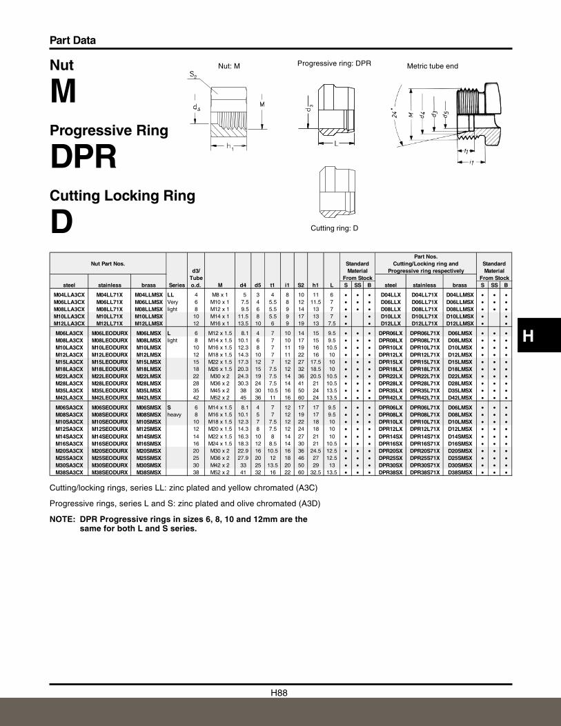
H88
Part Data
H
Nut
MProgressive Ring
DPRCutting Locking Ring
D
Progressive ring: DPRNut: M Metric tube end
Cutting/locking rings, series LL: zinc plated and yellow chromated (A3C)
Progressive rings, series L and S: zinc plated and olive chromated (A3D)
NOTE: DPR Progressive rings in sizes 6, 8, 10 and 12mm are thesame for both L and S series.
Cutting ring: D
3
Part Nos.Nut Part Nos. Standard Cutting/Locking ring and Standard
d3/ Material Progressive ring respectively MaterialTube From Stock From Stock
steel stainless brass Series o.d. M d4 d5 t1 i1 S2 h1 L S SS B steel stainless brass S SS B
M04LLA3CX M04LL71X M04LLMSX LL 4 M8 x 1 5 3 4 8 10 11 6 • • • D04LLX D04LL71X D04LLMSX • • •M06LLA3CX M06LL71X M06LLMSX Very 6 M10 x 1 7.5 4 5.5 8 12 11.5 7 • • • D06LLX D06LL71X D06LLMSX • • •M08LLA3CX M08LL71X M08LLMSX light 8 M12 x 1 9.5 6 5.5 9 14 13 7 • • • D08LLX D08LL71X D08LLMSX • • •M10LLA3CX M10LL71X M10LLMSX 10 M14 x 1 11.5 8 5.5 9 17 13 7 • • D10LLX D10LL71X D10LLMSX • •M12LLA3CX M12LL71X M12LLMSX 12 M16 x 1 13.5 10 6 9 19 13 7.5 • • D12LLX D12LL71X D12LLMSX • •
M06LA3CX M06LEODURX M06LMSX L 6 M12 x 1.5 8.1 4 7 10 14 15 9.5 • • • DPR06LX DPR06L71X D06LMSX • • •M08LA3CX M08LEODURX M08LMSX light 8 M14 x 1.5 10.1 6 7 10 17 15 9.5 • • • DPR08LX DPR08L71X D08LMSX • • •M10LA3CX M10LEODURX M10LMSX 10 M16 x 1.5 12.3 8 7 11 19 16 10.5 • • • DPR10LX DPR10L71X D10LMSX • • •M12LA3CX M12LEODURX M12LMSX 12 M18 x 1.5 14.3 10 7 11 22 16 10 • • • DPR12LX DPR12L71X D12LMSX • • •M15LA3CX M15LEODURX M15LMSX 15 M22 x 1.5 17.3 12 7 12 27 17.5 10 • • • DPR15LX DPR15L71X D15LMSX • • •M18LA3CX M18LEODURX M18LMSX 18 M26 x 1.5 20.3 15 7.5 12 32 18.5 10 • • • DPR18LX DPR18L71X D18LMSX • • •M22LA3CX M22LEODURX M22LMSX 22 M30 x 2 24.3 19 7.5 14 36 20.5 10.5 • • • DPR22LX DPR22L71X D22LMSX • • •M28LA3CX M28LEODURX M28LMSX 28 M36 x 2 30.3 24 7.5 14 41 21 10.5 • • • DPR28LX DPR28L71X D28LMSX • • •M35LA3CX M35LEODURX M35LMSX 35 M45 x 2 38 30 10.5 16 50 24 13.5 • • • DPR35LX DPR35L71X D35LMSX • • •M42LA3CX M42LEODURX M42LMSX 42 M52 x 2 45 36 11 16 60 24 13.5 • • • DPR42LX DPR42L71X D42LMSX • • •
M06SA3CX M06SEODURX M06SMSX S 6 M14 x 1.5 8.1 4 7 12 17 17 9.5 • • • DPR06LX DPR06L71X D06LMSX • • •M08SA3CX M08SEODURX M08SMSX heavy 8 M16 x 1.5 10.1 5 7 12 19 17 9.5 • • • DPR08LX DPR08L71X D08LMSX • • •M10SA3CX M10SEODURX M10SMSX 10 M18 x 1.5 12.3 7 7.5 12 22 18 10 • • • DPR10LX DPR10L71X D10LMSX • • •M12SA3CX M12SEODURX M12SMSX 12 M20 x 1.5 14.3 8 7.5 12 24 18 10 • • • DPR12LX DPR12L71X D12LMSX • • •M14SA3CX M14SEODURX M14SMSX 14 M22 x 1.5 16.3 10 8 14 27 21 10 • • • DPR14SX DPR14S71X D14SMSX • • •M16SA3CX M16SEODURX M16SMSX 16 M24 x 1.5 18.3 12 8.5 14 30 21 10.5 • • • DPR16SX DPR16S71X D16SMSX • • •M20SA3CX M20SEODURX M20SMSX 20 M30 x 2 22.9 16 10.5 16 36 24.5 12.5 • • • DPR20SX DPR20S71X D20SMSX • • •M25SA3CX M25SEODURX M25SMSX 25 M36 x 2 27.9 20 12 18 46 27 12.5 • • • DPR25SX DPR25S71X D25SMSX • • •M30SA3CX M30SEODURX M30SMSX 30 M42 x 2 33 25 13.5 20 50 29 13 • • • DPR30SX DPR30S71X D30SMSX • • •M38SA3CX M38SEODURX M38SMSX 38 M52 x 2 41 32 16 22 60 32.5 13.5 • • • DPR38SX DPR38S71X D38SMSX • • •
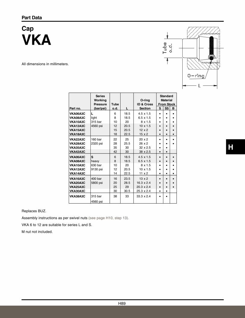
H89
Part Data
H
Cap
VKAAll dimensions in millimeters.
Replaces BUZ.
Assembly instructions as per swivel nuts (see page H10, step 13).
VKA 6 to 12 are suitable for series L and S.
M nut not included.
Series StandardWorking O-ring MaterialPressure Tube ID & Cross From Stock
Part no. (bar/psi) o.d. L Section S SS B
VKA06A3C L 6 18.5 4.5 x 1.5 • • •VKA08A3C light 8 18.5 6.5 x 1.5 • • •VKA10A3C 315 bar 10 20 8 x 1.5 • • •VKA12A3C 4560 psi 12 20.5 10 x 1.5 • • •VKA15A3C 15 20.5 12 x 2 • • •VKA18A3C 18 22.5 15 x 2 • • •
VKA22A3C 160 bar 22 25 20 x 2 • • •VKA28A3C 2320 psi 28 25.5 26 x 2 • • •VKA35A3C 35 30 32 x 2.5 • •VKA42A3C 42 30 38 x 2.5 • •
VKA06A3C S 6 18.5 4.5 x 1.5 • • •VKA08A3C heavy 8 18.5 6.5 x 1.5 • • •VKA10A3C 630 bar 10 20 8 x 1.5 • • •VKA12A3C 9130 psi 12 20.5 10 x 1.5 • • •VKA14A3C 14 22.5 11 x 2 • • •
VKA16A3C 400 bar 16 23.5 13 x 2 • • •VKA20A3C 5800 psi 20 28.5 16.3 x 2.4 • • •VKA25A3C 25 29 20.3 x 2.4 • • •VKA30A3C 30 30.5 25.3 x 2.4 • •
VKA38A3C 315 bar 38 33 33.3 x 2.4 • •
4560 psi
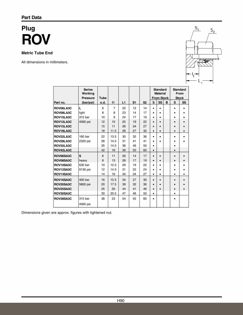
H90
Part Data
Plug
ROVMetric Tube End
All dimensions in millimeters.
Dimensions given are approx. figures with tightened nut.
Series Standard StandardWorking Material FromPressure Tube From Stock Stock
Part no. (bar/psi) o.d. I1 L1 S1 S2 S SS B S SS
ROV06LA3C L 6 7 22 12 14 • • • •ROV08LA3C light 8 8 23 14 17 • • • •ROV10LA3C 315 bar 10 9 24 17 19 • • • •ROV12LA3C 4560 psi 12 10 25 19 22 • • • •ROV15LA3C 15 11 26 24 27 • • • •ROV18LA3C 18 11.5 28 27 32 • • • •
ROV22LA3C 160 bar 22 13.5 30 32 36 • • • •ROV28LA3C 2320 psi 28 14.5 31 41 41 • • • •ROV35LA3C 35 14.5 36 46 50 • •ROV42LA3C 42 16 39 55 60 • •
ROV06SA3C S 6 11 26 14 17 • • • •ROV08SA3C heavy 8 13 28 17 19 • • • •ROV10SA3C 630 bar 10 12.5 29 19 22 • • • •ROV12SA3C 9130 psi 12 14.5 31 22 24 • • • •ROV14SA3C 14 16 34 24 27 • • • •
ROV16SA3C 400 bar 16 15.5 34 27 30 • • • •ROV20SA3C 5800 psi 20 17.5 39 32 36 • • • •ROV25SA3C 25 20 44 41 46 • • • •ROV30SA3C 30 20.5 47 46 50 • •
ROV38SA3C 315 bar 38 23 54 55 60 • •
4560 psi

Nantong Naco Fluid Equipment Co.,LTD
Pingchao Town, Tongzhou Area, Nantong City, jiangsu Province, ChinaTel:86-513-85400443 Fax:86-513-85400444
E-mail:[email protected]