Embed Size (px)
Citation preview
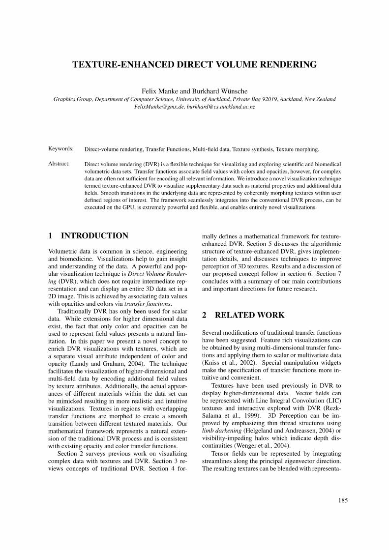
TEXTURE-ENHANCED DIRECT VOLUME RENDERING
Felix Manke and Burkhard WunscheGraphics Group, Department of Computer Science, University of Auckland, Private Bag 92019, Auckland, New Zealand
[email protected], [email protected]
Keywords: Direct-volume rendering, Transfer Functions, Multi-field data, Texture synthesis, Texture morphing.
Abstract: Direct volume rendering (DVR) is a flexible technique for visualizing and exploring scientific and biomedicalvolumetric data sets. Transfer functions associate field values with colors and opacities, however, for complexdata are often not sufficient for encoding all relevant information. We introduce a novel visualization techniquetermed texture-enhanced DVR to visualize supplementary data such as material properties and additional datafields. Smooth transitions in the underlying data are represented by coherently morphing textures within userdefined regions of interest. The framework seamlessly integrates into the conventional DVR process, can beexecuted on the GPU, is extremely powerful and flexible, and enables entirely novel visualizations.
1 INTRODUCTION
Volumetric data is common in science, engineeringand biomedicine. Visualizations help to gain insightand understanding of the data. A powerful and pop-ular visualization technique is Direct Volume Render-ing (DVR), which does not require intermediate rep-resentation and can display an entire 3D data set in a2D image. This is achieved by associating data valueswith opacities and colors via transfer functions.
Traditionally DVR has only been used for scalardata. While extensions for higher dimensional dataexist, the fact that only color and opacities can beused to represent field values presents a natural lim-itation. In this paper we present a novel concept toenrich DVR visualizations with textures, which area separate visual attribute independent of color andopacity (Landy and Graham, 2004). The techniquefacilitates the visualization of higher-dimensional andmulti-field data by encoding additional field valuesby texture attributes. Additionally, the actual appear-ances of different materials within the data set canbe mimicked resulting in more realistic and intuitivevisualizations. Textures in regions with overlappingtransfer functions are morphed to create a smoothtransition between different textured materials. Ourmathematical framework represents a natural exten-sion of the traditional DVR process and is consistentwith existing opacity and color transfer functions.
Section 2 surveys previous work on visualizingcomplex data with textures and DVR. Section 3 re-views concepts of traditional DVR. Section 4 for-
mally defines a mathematical framework for texture-enhanced DVR. Section 5 discusses the algorithmicstructure of texture-enhanced DVR, gives implemen-tation details, and discusses techniques to improveperception of 3D textures. Results and a discussion ofour proposed concept follow in section 6. Section 7concludes with a summary of our main contributionsand important directions for future research.
2 RELATED WORK
Several modifications of traditional transfer functionshave been suggested. Feature rich visualizations canbe obtained by using multi-dimensional transfer func-tions and applying them to scalar or multivariate data(Kniss et al., 2002). Special manipulation widgetsmake the specification of transfer functions more in-tuitive and convenient.
Textures have been used previously in DVR todisplay higher-dimensional data. Vector fields canbe represented with Line Integral Convolution (LIC)textures and interactive explored with DVR (Rezk-Salama et al., 1999). 3D Perception can be im-proved by emphasizing thin thread structures usinglimb darkening (Helgeland and Andreassen, 2004) orvisibility-impeding halos which indicate depth dis-continuities (Wenger et al., 2004).
Tensor fields can be represented by integratingstreamlines along the principal eigenvector direction.The resulting textures can be blended with representa-
185
tions for different tissue types by using derived tensorquantities as input for a classification function whichencodes the probability that a field value correspondsto a certain tissue type (Wunsche and Lobb, 2004).
Patel et al. (Patel et al., 2007) illustrate volumet-ric seismic data by mapping 2D textures onto the pla-nar faces of axis-aligned cutouts. For the rendering,”Layer texture transfer functions” are used to selecttextures, scaling factors, and opacities for the pre-classified layers. ”Scalar texture transfer functions”associate different materials with textures. Duringrendering, the opacities are used to linearly blend the2D textures. A separate conventional color-opacitytransfer function maps data values to RGBα colors,which can be blended with the textures.
3 MATHEMATICAL MODEL FORDVR
Traditional DVR is described by the emission-absorption model, where scalar values are interpretedas densities of a gaseous material which emits and ab-sorbs light (Max, 1995). An image is created by accu-mulating the total light intensity for each pixel whichin the simplest case is computed as
C =∫
∞
0c(t)e−
∫ t0 κ(u)dudt (1)
where t is the parameter of a viewing ray through apixel, C is its color, c(t) the color at the ray parametert and the integral in the exponent is the total opacityof the ray segment [0, t] which is computed by inte-grating densities (opacities) along the ray.
The DVR integral in equation 1 requires transferfunctions which associate values of a volume with op-tical properties. In the traditional DVR model (Max,1995) these are three color components (red, green,and blue) and an opacity component (α). AlthoughMax assumes scalar volume data sets only, subse-quent work uses higher dimensional input data suchas vectors and tensors (Helgeland and Andreassen,2004). Consequently we define a volume as a moregeneral function f : Rn 7→ Rm, with n independentvariables, such as position and time, and m dependentvariables, e.g., m = 3 for vector data.
In addition we introduce a data transformation op-erator B that maps a function f : Rn 7→Rm (input dataset) to a function g : Rn 7→ Rk (derived data set):
B: f 7→ g. (2)
This operator reflects that many applications use de-rived quantities as input for the DVR process. Forexample, multi-dimensional transfer functions using
scalar data and its gradient are useful for detectingmaterial boundaries (Kniss et al., 2002).
The output of function g is a k-dimensional vectorthat serves as input for the transfer function. Using B,the color-opacity transfer function can be defined as:
Θ : Rk 7→ R4
Θ(B( f )(P)
)= Θ
(g(P)
)= (C,α). (3)
The transfer functions themselves are weightingfunctions for RGBα values and are usually either user-defined using simple manipulation widgets (Knisset al., 2002), or are predefined, e.g., using typical tis-sue densities for CT data.
4 MATHEMATICALFRAMEWORK FORTEXTURE-ENHANCED DVR
In order to obtain consistency with the existing DVRmodel, texture transfer functions should enable the as-sociation of data values with different textures anal-ogous to traditional transfer functions, i.e., by usingweighting functions defined over the domain of thedependent variables.
The following difficulties exist: In contrast to col-ors and opacities, textures have spatial (and poten-tially temporal) properties and hence must also de-pend on the independent variables. Transfer functionswhich overlap within the domain of an independentvariable, require a merging of textures. Whereas col-ors and opacity values can be (linearly) interpolated,the morphing of textures must maintain the character-istics of each individual texture used to represent theunderlying data set, e.g., size, color and orientationof texture components. Since textures are also repre-sented by color and opacities a mechanism must befound to combine them with the results of the colorand opacity transfer functions.
The mathematical framework for texture-enhanced DVR is hence defined as follows:
4.1 Defining Texture Coordinates
Each texture object T(Ω,ς) has its own dimensional-ity p, domain Ω (where the texture is used in the vi-sualization), and attribute function ς (usually RGBα,but other values such as displacements are possible).Consequently, the texture coordinates Q have to bedefined per texture. For volume rendering the tex-ture coordinates depend on the spatial locations of thevoxels. This requirement is consistent with existingtexture-based visualization techniques such as LIC:
GRAPP 2009 - International Conference on Computer Graphics Theory and Applications
186
the texture generation only effects the attribute func-tion ς, but not the definition of texture coordinates orweighting-curves used for rendering them.
In order to obtain texture coordinates for a textureT(Ω,ς), we define a function Γ that maps voxel posi-tions P ∈ Rn to texture coordinates Q ∈Ω⊆ Rp:
Γ : Rn 7→ Rp
Γ : P 7→ Γ(P) = Q.(4)
Note that the equation makes no assumptionsabout the dimensionality of T. In our examples p = 3and Ω can be a subset of the input data set as ex-plained in subsection 5.2. The definition of Γ allowsspatially varying transformations, e.g. gradual scalingor rotation of textures and their features.
4.2 Texture Transfer Functions
Instead of returning colors and opacities, the newtransfer function returns a vector of weights (one foreach of the L textures) used for the classification:
Θtex : Rk 7→ RL
Θtex(B( f )(P)
)= ω.
(5)
Note that, in contrast to the conventional transferfunction, Θtex does not map into R4(RGBα), but intoan L-dimensional space (RL). This makes it possibleto morph textures and define texture-dependent shad-ing and transparency effects to improve perception.
4.3 Morphing of Textures
A morphing operator needs access to the texture trans-fer function Θtex in order to obtain weights for neigh-boring pixels. In addition morphing requires for allL textures the texture attributes at all texels, and notjust their values at a given voxel. Hence, the operatorneeds L texture coordinates Q1···L and the functionsς1···L as input. In order to further increase flexibility,it is better not to provide the pre-transformed texturecoordinates, but instead the transformation functionsΓ1···L together with the current voxel position P. Inthis way, a morphing operator is able to access neigh-boring voxels and texels. Since the transformationfunctions Γ1···L determine the texture domain the ex-plicit specification of Ω1···L is not necessary.
Taken all these considerations into account, themorphing operator can be defined as follows:(
(C,α)tex, Λ)=
[P, Γ1···L, ς1···L, f , B, Θtex
]. (6)
where Λ denotes additional channels such as dis-placement values. Note that for efficiency the morph-ing, even though defined for the entire volume, should
be performed only for the subset of f which, accord-ing to the transfer functions will be visible and con-tribute to the final image (see subsection 5.2).
We have developed a fast exemplar-based texturesynthesis and morphing algorithm. The techniqueprovides an excellent trade-off between speed andquality, is highly flexible, allows the use of arbitrarychannels, can be extended to arbitrary dimensions andis suitable for a GPU-implementation. Technical de-tails are given in (Manke and Wunsche, 2009).
4.4 Color Combination Operator
The evaluation of the texture transfer function Θtexand the application of the morphing operator form aparallel path in the DVR process, which is indepen-dent of the evaluation of the color and opacity trans-fer function. In order to integrate texture-enhancedDVR into the existing process, the binary color com-bination operator ~ mixes the color-opacity pairs(C,α)conv of the conventional transfer function and(C,α)tex of the texture. Formally, ~ is defined as:
~ : RGBα×RGBα 7→ RGBα
(C,α) = (C,α)conv ~ (C,α)tex.(7)
The color combination operator ~ has differentmodes implementing simple operations, such as re-placement of the results of the color transfer func-tion, and more complex operations combining col-ors and transparencies. This is consistent with theOpenGL texture environment modes GL REPLACE,GL MODULATE etc. for polygon rendering.
5 IMPLEMENTATION
The volume rendering integral in equation 1 can be ef-ficiently solved on graphics hardware by discretizingthe volume using object or view-aligned slices, com-puting colors and transparencies for each slice, andcompositing them in back-to-front order:
(Ci,αi)conv <- evaluate Θ(B( f )(P)
)// eval. of conv. transfer function(
(C,α)tex, Λ)<-
[P, Γ1···L, ς1···L, f , B, Θtex
]// morphing of textures
(Ci,αi) <- (Ci,αi)conv ~ (Ci,αi)tex// combination of colors
c′i <- (αi ·Ci)+(1−αi) · c′i−1// volumetric compositing
The extensions can be directly integrated into amodular GPU-based DVR framework we presentedpreviously (Manke and Wunsche, 2008). Sampling
TEXTURE-ENHANCED DIRECT VOLUME RENDERING
187
the texture transfer function generates weight mapswhich are used in the texture morphing algorithm.
W j(P)⇔Θtex(B( f )(P)
)= ω j, 1≤ j ≤ L.
More implementation and technical details, andthe source code are available at (Manke, 2008).
5.1 Perceptual Issues
One of the major difficulties in using 3D textures forvisualization is perception of their spatial properties.While the human visual system is well adapted toperceive textures over surfaces and even uses themas depth and shape cues, it is very difficult to per-ceive partially transparent solid textures. The chal-lenges are similar as for conventional color and opac-ity transfer functions where the naive approach of justaccumulating colors and opacities results in a fuzzyimage without visible structures. These problems areovercome by using shading functions which empha-size material boundaries, e.g., by using the gradientmagnitude of the scalar input data set as pseudo sur-face normal (Levoy, 1988). Based on experimentaland visual perception research we developed the fol-lowing guidelines for using texture-enhanced DVR:
For data sets where only recognition of materialtypes and properties is important, rather than theirexact 3D structure, we use opacity transfer func-tions which make the region of interest nearly opaqueand the remaining features nearly transparent. Inte-rior structures can be shown by using cutting planes.The method results in images similar to Patel etal.’s approach (Patel et al., 2007), but offers smoothboundaries between materials using texture morphingand we can indicate important features or anatomicallandmarks by partial transparent surfaces.
A better perception of the 3D structure of tex-tures is obtained by using screen-door transparencies.Here, the alpha channel of the synthesized texture isused to model different opacities for the texture ele-ments. For screen-door transparency, selected parts ofthe texture are defined to be fully opaque, whereas allother parts are defined to be (almost) fully transpar-ent. The color combination operator then multipliesthe opacities α given by (C,α)conv and (C,α)tex.
We utilize the synthesis of additional channels forgenerating the alpha channel: In addition to the colorinput exemplar, an additional 2D texture is definedthat encodes opacities. After the texture morphinghas finished, the texture coordinates stored in the fi-nal synthesis pyramids can be used to look up pixelsin this additional texture. Perception of the geometryof opaque texture elements, rather than the texturedsurface, can be improved by using the gradient of the
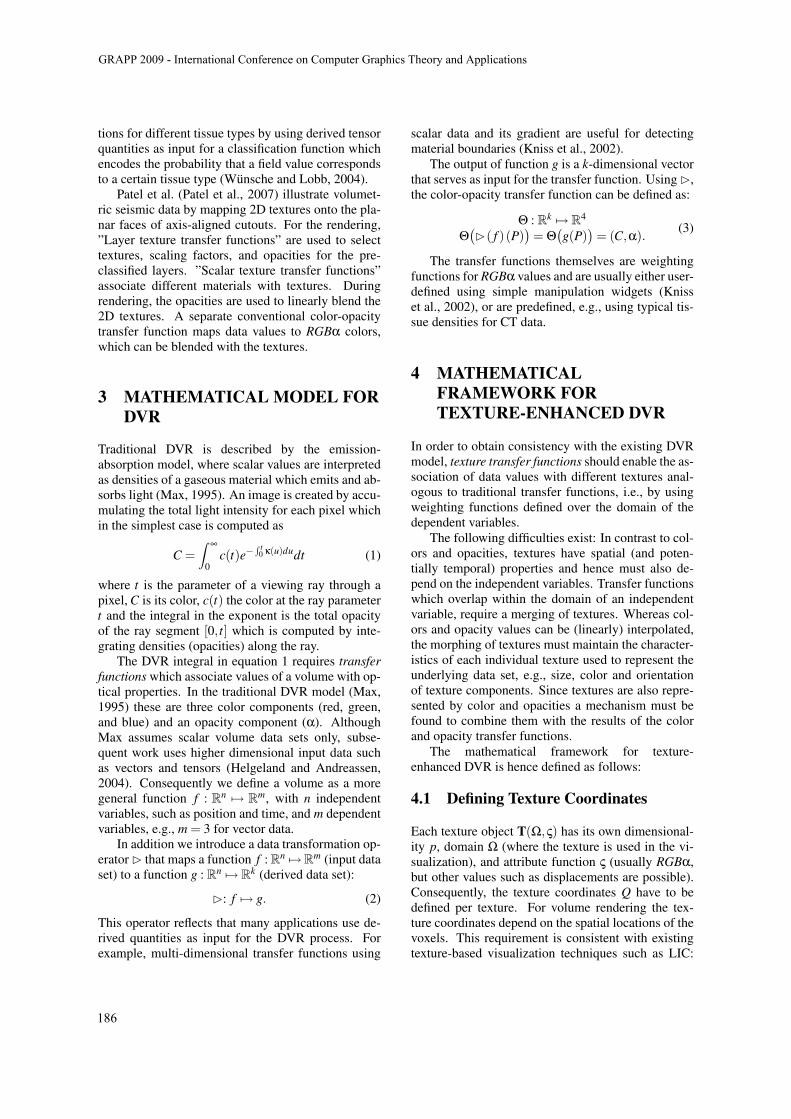
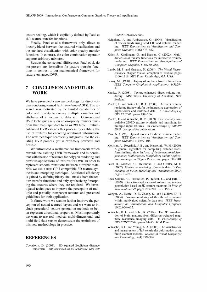
Figure 1: A binary shell mask (blue) with dilation radiusrd = 5 for a binary object mask (red).
scalar field g(P) = f (P) · a(P) as illumination func-tion. Here f denotes the data set and a is a functionthat returns the geometry-defining alpha value of thesolid texture at a sample point P.
5.2 Binary Shell Masks
In DVR the visualized data typically contains largeregions that are of no interest and hence defined by thetransfer function as fully transparent. Since texturesynthesis and morphing is a time consuming processit is desirable for texture-enhanced DVR to generatesolid textures only where they are required.
We realize partial texture synthesis and morphingby integrating a binary object mask into the basic 3Dtexture morphing algorithm. This binary object maskB is of the same size as the target texture cube S, andencodes which voxels of S are textured. Because ourtexture synthesis algorithm uses neighborhood match-ing and a multi-resolution approach, the binary objectmask B is dilated by a user-defined dilation radius rd(figure 1). In order to compute the shortest Euclideandistance of each voxel to the binary object mask, weadopt a C++ implementation by (Coeurjolly, 2003)that realizes a linear-time algorithm for computing the3D squared Euclidean Distance Transform (Meijsteret al., 2000). In practice we found that a dilation ra-dius rd = 10 yields high quality textures while stillresulting in significant time savings.
6 RESULTS AND DISCUSSION
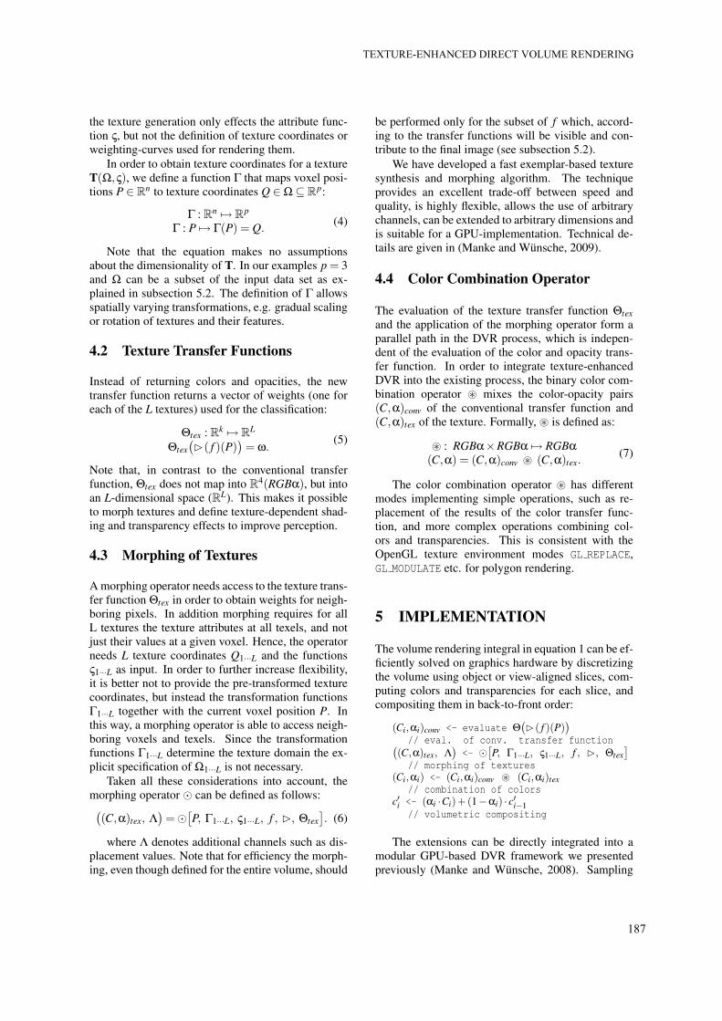
We compared conventional transfer functions withtexture transfer functions (figure 2) and found that foropaque textured layers, such as the bone layer in thefigure, texture transfer functions enable similar per-ception of features. The geometry of semi-transparentlayers, such as the skin layer of the nose, is harderto perceive than for conventional transfer functions.
GRAPP 2009 - International Conference on Computer Graphics Theory and Applications
188
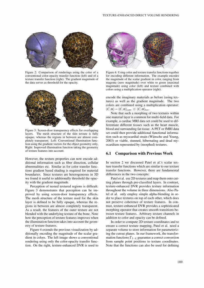
Figure 2: Comparison of renderings using the color of aconventional color-opacity transfer function (left) and of atexture transfer function (right). The gradient magnitude ofthe data serves as threshold for the opacity.
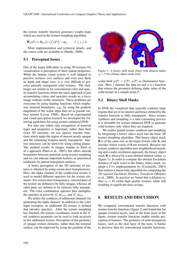
Figure 3: Screen-door transparency effects for overlappinglayers. The mesh structure of the skin texture is fullyopaque, whereas the regions in between are almost com-pletely transparent. Left: Conventional illumination func-tion using the gradient vectors for the object geometry only.Right: Improved illumination function taking the geometryof texture features into account.
However, the texture properties can now encode ad-ditional information such as fiber direction, cellularabnormalities etc. Similar as for color transfer func-tions gradient based shading is required for materialboundaries. Since textures are heterogeneous in 3Dwe found it useful to additionally threshold the opac-ity with the gradient magnitude.
Perception of nested textured regions is difficult.Figure 3 demonstrates that perception can be im-proved by using screen-door transparency effects.The mesh structure of the texture used for the skinlayer is defined to be fully opaque, whereas the re-gions in between are almost completely transparent.As a result, the features of the outer texture are notblended with the underlying texture of the bone. Notehow the perception of texture features improves whenthe illumination function takes into account the geom-etry of texture features.
Figure 4 extends the previous visualization by ad-ditionally encoding the magnitude of the scalar gra-dient in colors. The left image shows a conventionalrendering using only the color-opacity transfer func-tion. On the right, texture-enhanced DVR is used to
Figure 4: Using color and texture transfer functions togetherfor encoding different information. The example encodesthe magnitude of the scalar gradient in color, ranging frommagenta (zero magnitude) over white to green (maximalmagnitude) using color (left) and texture combined withcolors using a multiplication operator (right).
encode the imaginary materials as before (using tex-tures) as well as the gradient magnitude. The twocolors are combined using a multiplication operator:(C,α) = (C,α)conv ⊗ (C,α)tex.
Note that such a morphing of two textures withinone material layer is common for multi-field data. Forexample, a cardiac MRI data set could be used to dif-ferentiate different tissues such as the heart muscle,blood and surrounding fat tissue. A PET or fMRI dataset could then provide additional functional informa-tion such as myocardial strain (Wunsche and Young,2003) or viable, stunned, hibernating and dead my-ocardium represented by (morphed) textures.
6.1 Comparison with Previous Work
In section 2 we discussed Patel et al.’s scalar tex-ture transfer functions which are similar to our texturetransfer functions. However, there are fundamentaldifferences in the two concepts:
Patel et al. use 2D textures and map them onto cut-ting planes through pre-classified layers. In contrast,texture-enhanced DVR provides texture informationthroughout the volume in three dimensions. Also Pa-tel et al. only employ simple alpha-blending in or-der to place textures on top of each other, which doesnot preserve coherence of texture features. In con-trast, texture-enhanced DVR provides a sophisticatedmorphing operator that creates smooth transitions be-tween texture features. Arbitrary texture channels inaddition to color and opacity can be defined.
In order to compute 2D texture coordinates and toensure a correct texture mapping, Patel et al. need aseparate volume to store information for parameteriz-ing the cutout planes. In our framework, the transfor-mation functions Γ1···L guarantee a correct conversionfrom sample point positions to texture coordinates.Note that the functions can also be used for defining
TEXTURE-ENHANCED DIRECT VOLUME RENDERING
189
texture scaling, which is explicitly defined by Patel etal.’s texture transfer functions.
Finally, Patel et al.’s framework only allows tolinearly blend between the textured visualization andthe standard visualization with color-opacity transferfunctions. In contrast, the color combination operatorsupports arbitrary mixtures.
Besides the conceptual differences, Patel et al. donot present any formalism for texture transfer func-tions in contrast to our mathematical framework fortexture-enhanced DVR.
7 CONCLUSION AND FUTUREWORK
We have presented a new methodology for direct vol-ume rendering termed texture-enhanced DVR. The re-search was motivated by the limited capabilities ofcolor and opacity to convey multiple variables andattributes of a volumetric data set. ConventionalDVR techniques rely on color-opacity transfer func-tions that map input data to an RGBα tuple. Texture-enhanced DVR extends this process by enabling theuse of textures for encoding additional information.The new technique seamlessly integrates into the ex-isting DVR process, yet is extremely powerful andflexible.
We introduced a mathematical framework whichextends the existing DVR framework and is consis-tent with the use of textures for polygon rendering andprevious applications of textures for DVR. In order torepresent smooth transitions between different mate-rials we use a new GPU-compatible 3D texture syn-thesis and morphing technique. Additional efficiencyis gained by defining binary shell masks from the tex-ture transfer functions and only synthesizing / morph-ing the textures where they are required. We inves-tigated techniques to improve the perception of mul-tiple and partially transparent textures and presentedguidelines for their application.
In future work we want to further improve the per-ception of nested textured layers and we want to in-clude procedural texture generation methods to bet-ter represent directional properties. Most importantlywe want to use real medical multi-dimensional andmulti-field data sets to demonstrate the usefulness ofthis new methodology in practice.
REFERENCES
Coeurjolly, D. (2003). 3D squared Euclidean distancetransform. http://www.cb.uu.se/˜ tc18/code data set/
Code/SEDT/index.html.
Helgeland, A. and Andreassen, O. (2004). Visualizationof vector fields using seed LIC and volume render-ing. IEEE Transactions on Visualization and Com-puter Graphics, 10(6):673–682.
Kniss, J., Kindlmann, G., and Hansen, C. (2002). Multi-dimensional transfer functions for interactive volumerendering. IEEE Transactions on Visualization andComputer Graphics, 8(3):270–285.
Landy, M. S. and Graham, N. (2004). The Visual Neuro-sciences, chapter Visual Perception of Texture, pages1106–1118. MIT Press, Cambridge, MA, USA.
Levoy, M. (1988). Display of surfaces from volume data.IEEE Computer Graphics & Applications, 8(3):29–37.
Manke, F. (2008). Texture-enhanced direct volume ren-dering. MSc thesis, University of Auckland, NewZealand.
Manke, F. and Wunsche, B. C. (2008). A direct volumerendering framework for the interactive exploration ofhigher-order and multifield data. In Proceedings ofGRAPP 2008, pages 199–206.
Manke, F. and Wunsche, B. C. (2009). Fast spatially con-trollable 2D/3D texture synthesis and morphing formultiple input textures. In Proceedings of GRAPP2009. (accepted for publication).
Max, N. (1995). Optical models for direct volume render-ing. IEEE Transactions on Visualization and Com-puter Graphics, 1(2):99–108.
Meijster, A., Roerdink, J. B., and Hesselink, W. H. (2000).A general algorithm for computing distance trans-forms in linear time. In Proc. of the International Sym-posium on Mathematical Morphology and its Applica-tions to Image and Signal Processing, pages 331–340.
Patel, D., Giertsen, C., Thurmond, J., and Groller, M. E.(2007). Illustrative rendering of seismic data. In Pro-ceedings of Vision Modeling and Visualization 2007,pages 13–22.
Rezk-Salama, C., Hastreiter, P., Teitzel, C., and Ertl, T.(1999). Interactive exploration of volume line integralconvolution based on 3D-texture mapping. In Proc. ofVisualization ’99, pages 233–240. IEEE Press.
Wenger, A., Keefe, D. F., Zhang, S., and Laidlaw, D. H.(2004). Volume rendering of thin thread structureswithin multivalued scientific data sets. IEEE Trans-actions on Visualization and Computer Graphics,10(6):664–672.
Wunsche, B. C. and Lobb, R. (2004). The 3D visualiza-tion of brain anatomy from diffusion-weighted mag-netic resonance imaging data. In Proceedings ofGRAPHITE 2004, pages 74–83. ACM Press.
Wunsche, B. C. and Young, A. A. (2003). The visualizationand measurement of left ventricular deformation usingfinite element models. Journal of Visual Languagesand Computing, 14(4):299–326.
GRAPP 2009 - International Conference on Computer Graphics Theory and Applications
190