Embed Size (px)
Citation preview


INTRODUCTION
The products described in the TEXIO General Catalog are listed in a separate selection guide, which classify the
products according to the instrument types and groups, and shows the features and specications of each. Please
use this catalog as a guide when ordering.
All of the products listed in this catalog may not be marketed in your local area or country. Please check with
your TEXIO distributor or send an inquiry to us through our web-site, http://www.texio.co.jp .
Readers are able to learn about new products released after the publication of this catalog through your TEXIO
distributor or dealer. We are able to also provide you with new product information on our web-site.
The design and specications of the products listed in this catalog are subject to change without prior notice. In
addition, please note that some of the products may be discontinued without prior notice.
For product prices and available services, please contact your local TEXIO dealer.
* In producing this catalog we have made maximum eorts to provide as correct information as possible. Howev-
er, should you nd any misprints or errors, please let us know.
TEXIO…Providing Industry with the Most Valuable Measurement Technology.
Nowadays, new products featuring high-tech advances appear in dizzying succession. As we head toward a new
age in technology, advances in electronics-oriented leading-edge elds in particular continue to accelerate.
Supporting this new wave of the technical revolution from the bottom up is electronic measurement technology.
TEXIO’s initial technological and industrial triumphs were in the eld of general purpose measurement equip-
ments for audio manufacturers. Following those rst successes, TEXIO went on to develop multiple-output
Regulated DC Power Supplies for electric engineers in rapid succession. Those developments led in turn to
develop various Regulated DC Power Supplies and Test and Measuring Instruments.
In a constant pursuit of better performance and quality for its products, which are the pride of those ages, TEXIO
has made continuous and solid progress in the area of measurement technology. Indeed, we could say that
TEXIO’s advances in product development technology resulted from the evolution of measurement technology.
Electronic measurement technology of this sort has consistently supported and equipment made their way to the
market as TEXIO moved forward. That is the main reason why TEXIO has continued to lead the market in these
leading-edge elds. Never content to rest on its laurels, TEXIO draws on its hi-tech achievements to introduce
technology using advanced technology, all the while working steadily to open up new elds of endeavor.
“Technological evolution and the technology to support it” The geometric eect accruing from this combination
has become the foundation for TEXIO’s outstanding creativity and far-sightedness.
TEXIO considers “superior precision and superior quality” as essential to ongoing progress. Relying on a founda-
tion of precision measurement technology, outstanding technical know-how and quick response to developments
in leading-edge technology, TEXIO continues to make major contributions in many elds toward technical
advances, superior reliability and rationalization by providing the “mother tools” of industry.
Proud of its achievements, TEXIO will redouble its eorts to remain a trailblazer in the eld of leading-edge
electronic technology.

3
Corporate Profile
History
Company name TEXIO TECHNOLOGY CORPORATION
Founded October 2012
Capital J. Yen 90 million
President Tsung-Huei Teng (Mr.)
Holding company GOOD WILL INSTRUMENT CO., LTD.
Business categories Test and Measuring Instruments and DC Power Supplies design, development, manufacturing and distribution
Products Regulated DC Power Supplies, Electronic Loads, Oscilloscopes, Electronic measurement devices and others
Employees 45 (as of Octorber 2018)
Transaction bank Sumitomo Mitsui Banking CorporationMUFG Bank, Ltd.
Headquarters 7F Towa Fudosan Shin Yokohama Bldg., 2-18-13 Shin Yokohama, Kohoku-ku, Yokohama, Kanagawa, 222-0033 Japan TEL +81(0)45-620-2305 FAX +81(0)45-534-7181
URL https//www.texio.co.jp/
Japan Domestic oces KITA - NIHON Sales Oce (Omiya)HIGASHI - NIHON Sales Oce (Yokohama)NAKA - NIHON Sales Oce (Nagoya)NISHI - NIHON Sales Oce (Osaka)
1 9 5 4 Produced 1st measurement device SG-1/RS-1 (Kasuga Musen)
1 9 6 5 Developed 1st oscilloscope CO-130 (TRIO)
1 9 7 3 Developed regulated DC power supply PR-601/PR602 (TRIO)
1 9 8 8 Developed digital storage oscilloscope CS-8010 (Kenwood)
1 9 8 9 Developed multiple-output regulated DC power supply PW series (Kenwood)
1 9 9 2 Developed switching power supply PS series (Kenwood)
1 9 9 6 Established Kenwood TMI Corporation.
1 9 9 9 Developed Electronic load device PEL-201 series (Kenwood)
2 0 0 2 Nikke group acquires 100% of shares, became part of Nikke Group
2 0 0 6 Developed exible range regulated DC power supply PSF-L series (Kenwood)
Changed name to Texio Corportion.
2 0 0 9 Nikke regrouped subsidiary companies and establised Nikke Techno System Co., Ltd. TEXIO was incorporated into the company as TEXIO division.
2 0 1 2 Developed Electronic load LSA series (TEXIO)
GOOD WILL INSTRUMENT CO., LTD took over TEXIO division of Nikke Techno System and established TEXIO TECHNOLOGY CORPORATION.
Developed hybrid method regulated DC power supply PDS-A series. (TEXIO)
2 0 1 4 TEXIO TECHNOLOGY CORPORATION merged with INSTEK JAPAN CORPORATION on January.
2 0 1 5 Developed Digital Storage Oscilloscope DCS-2000E Series. (TEXIO)Developed Programmable AC power source APS-7000 Series.(GW)
2 0 1 6 Developed Arbitray function generator AFG-303x Series.(GW) 2 0 1 7 Developed Power meter GPM-8213.(GW) 2 0 1 8 Developed Digital Storage Oscilloscope MDO-2000E Series.(GW)
Developed Multi-Range D.C. Power Supply PFR-100 Series.(TEXIO)

4
Multi-Range DC Power Supplies
PSW Series Switching
PSW-360L30PSW-720L30PSW-1080L30PSW-360L80PSW-720L80PSW-1080L80PSW-360M160PSW-720M160PSW-1080M160PSW-360M250PSW-720M250PSW-1080M250PSW-360H800PSW-720H800PSW-1080H800
The PSW-Series is a single-output multi-range programmable switching DC
Power Supply covering a power range up to 1080W.
This series of products include fteen models with the combination of 30V,
80V, 160V,250V and 800V rated voltages and 360W, 720W and 1080W
maximum output powers.
Voltage Rating: 30V/80V/160V/250V/800V, Output Power Rating: 360W to
1080W
Constant Power Output for Multiple Range (V&I) Operation
CV/CC Priority; Particularly Suitable for the Battery and LED Industry
Adjustable Slew Rate
Series Operation: Up to 2 units (30V, 80V, 160V models only)
Parallel Operation: Up to 3 units
High Eciency and High Power Density
1/2, 1/3, 1/6 Rack Mount Size Design (EIA/JIS Standard) for
360W/720W/1080W
Standard Interface: LAN,USB,Analog Control Interface
Optional Interface: GPIB-USB Adaptor, RS-232C-USB Adaptor
LabView Driver
ModelOutput Rating Ripple Line regulation Load regulation
DimensionsW×H×D(mm)
Max. dimensions W×H×D(mm)
Power consumption VA(approx.)
Weight kg (approx.)Power Voltage/Current
CV CC CV CC CV CCmVrms mArms mV mA mV mA
PSW-360L30 360W 0-30V/0-36A 7 72 18 41 20 41 71×124×350 71×137×400 500VA 3
PSW-720L30 720W 0-30V/0-72A 11 144 18 77 20 77 142×124×350 142×137 x 400 1000VA 5
PSW-1080L30 1080W 0-30V/0-108A 14 216 18 113 20 113 214×124×350 214×137×400 1500VA 7
PSW-360L80 360W 0-80V/0-13.5A 7 27 43 18.5 45 18.5 71×124×350 71×137×400 500VA 3
PSW-720L80 720W 0-80V/0-27A 11 54 43 32 45 32 142×124×350 142×137×400 1000VA 5
PSW-1080L80 1080W 0-80V/0-40.5A 14 81 43 45.5 45 45.5 214×124×350 214×137×400 1500VA 7
PSW-360M160 360W 0-160V/0-7.2A 7 15 83 12.2 85 12.2 71×124×350 71×137×400 500VA 3
PSW-720M160 720W 0-160V/0-14.4A 15 30 83 19.4 85 19.4 142×124×350 142×137×400 1000VA 5
PSW-1080M160 1080W 0-160V/0-21.6A 20 45 83 26.6 85 26.6 214×124×350 214×137×400 1500VA 7
PSW-360M250 360W 0-250V/0-4.5A 15 10 128 9.5 130 9.5 71×124×350 71×137×400 500VA 3
PSW-720M250 720W 0-250V/0-9A 15 20 128 14 130 14 142×124×350 142×137×400 1000VA 5
PSW-1080M250 1080W 0-250V/0-13.5A 15 30 128 18.5 130 18.5 214×124×350 214×137×400 1500VA 7
PSW-360H800 360W 0-800V/0-1.44A 30 5 403 6.44 405 6.44 71×124×350 71×137×400 500VA 3
PSW-720H800 720W 0-800V/0-2.88A 30 10 403 7.88 405 7.88 142×124×350 142×137×400 1000VA 5
PSW-1080H800 1080W 0-800V/0-4.32A 30 15 403 9.32 405 9.32 214×124×350 214×137×400 1500VA 7
OptionsGUR-001 RS-232C Interface PSW-006 Connection cable for PSW in parallel
connection (2unit) GET-001 Extention Output Terminal (Under 160V)
GUG-001 GP-IB Interface PSW-007 Connection cable for PSW in parallel connection (3unit) GET-002 Extention Output Terminal (Over 250V)
PSW-001 Connector kit for PSW Series analog control GTL-123 Test lead (Max.40A) GRA-410-J Rack Mount Kit (JIS)
PSW-005 Connection cable for PSW in series connection GTL-130 Test lead for PSW 250V/800V GRA-410-E Rack Mount Kit (EIA)
0
20
40
60
80
100
0 5 10 15 20 25 30 35 40 45
Voltage(V)
Current (A)
PSW 80V Series Operating Area
360W
720W
1080W
13.59.04.5 27 40.5
80
26.6
05101520253035
0 20 40 60 80 100 120
Voltage(V)
Current (A)
PSW 30V Series Operating Area
360W
720W
1080W
12 24 36 72 108
30
10
020406080100120140160180
0 5 10 15 20 25
Voltage(V)
Current (A)
PSW 160V Series Operating Area
360W
720W
1080W
2.25 4.5 6.75 7.2 14.4 21.6
160
50
0100200300400500600700800900
0 1 2 3 4 5
Voltage(V)
Current (A)
PSW 800V Series Operating Area
360W
720W
1080W
0.45 0.9 1.35 1.44 2.88 4.32
800
250
0
50
100
150
200
250
300
0 2 4 6 8 10 12 14
Voltage(V)
Current (A)
PSW 250V Series Operating Area
360W
720W
1080W
1.44 2.88 4.32 4.5 9 13.5
250
80

Fanless Multi-Range DC Power Supplies
PFR Series Switching
PFR-100L50PFR-100L50G*PFR-100M250PFR-100M250G*
The PFR-100 series, a small and high-performance programmable D.C. power
supply, adopts natural convection design to dissipate heat. The PFR-100 series
is a power supply with a ve-fold rated power that allows users to self-dene
voltage and current under rated power conditions so as to satisfy them with
wider voltage and current operational ranges. The PFR-100 series, with rated
100W, provides two models: PFR-100L50 maximum output voltage of 50V (at
2A) or maximum output current of 10A (at 10V); PFR-100M250 maximum
output voltage of 250V (at 0.4A) or maximum output current of 2A (at 50V).
Constant Power Output for 5 Times Multi-range(V&I) Operation
Natural Convection Cooling Design (Fanless Structure)
Preset Memory Function
Output ON/OFF Delay Function
CV, CC Priority Mode
Adjustable Slew Rate For Voltage and Current
Bleeder Circuit Control
Protections: OVP, OCP, AC FAIL and OTP
Support Front and Rear Panel Output
Test mode function (Sequence)
Built-in USB and RS-232/485 Interface
Built-in LAN and GPIB Interface (G Type)
Web Server Monitoring and Control
External Analog Control and Monitor Function
Remote Sensing Function
Dimension 71 x 124 x 301(mm), Weight Approx 2.5(kg)LabVIEW Driver
*G Type: With GP-IB/LAN interface
PFR-100M250 Operating Area
100W
×5
×5
PFR-100L50 Operating Area
100W
×5
×5
txxx.csv
The test mode is a function to automatically update voltage and current settings according to the time. The setting creates a CSV le on the PC and loads it into PFR using the USB ash drive, so it can use it without dicult operation..
Voltag
e/C
urr
ent
Time
5
Specications
Model Rating Power
Output Ripple Line regulation Load regulationDimensions
W×H×D(mm)Max. dimensions
W×H×D(mm)
Power consumption
W/VA(approx.)
Weight kg (approx.)(Voltage,Current)
CV CC CV CC CV CC
mVrms mArms mV mA mV mA
PFR-100L50 100W 0V-50V, 0A-10A 4 10 8 8 10 10 71× 124 × 3 0 1 71× 143 × 3 2 0 150VA 2.5
PFR-100M250 100W 0V-250V, 0A-2A 15 2 30 1.2 33 3.2 71× 124 × 3 0 1 71× 143 × 3 2 0 150VA 2.5

Regulated DC Power Supplies
PSF-400H (800V/3A/400W)
PSF-800H (800V/6A/800W)
PSF-H Series90˚ Rotating Panel
Specications
Model Rating Power
Output Ripple Line regulation Load regulationDimensions
W×H×D(mm)Max. dimensions
W×H×D(mm)
Power consumption
W/VA(approx.)
Weight kg (approx.)(Voltage,Current)
CV CC CV CC CV CC
mVrms mArms mV mA mV mA
PSF-400H 400W 0V-800V, 0A-3A 20 15 100 11.5 110 16.5 210 × 124 × 290 229 × 143 × 304 560VA 5
PSF-800H 800W 0V-800V, 0A-6A 25 20 100 13 110 18 210 × 124 × 290 229 × 143 × 304 1120VA 6
V(V)
I (A)1
Output Power line
2 4 6
133200
400
800 Output range of PSF-800H
High voltage Flexible range
Main ApplicationsHigh-voltage capacitors or relays used for hybrid cars, electric cars, solar power system and high-voltage LED lighting equipment.
6 times of exible output rangePSF-800H covers output for several units of conventional type regulated power supplies within 800W ( max voltage 800V, max current 6A. ).
Constant Power ControlCP mode is available in addition to CV and CC modes.
Changeable setting styleVertical or horizontal setting by 90°rotating panel.
Sequence OperationStand-alone sequence is available with the insidememory programmed by PC, through the optional control board (IF-60GP, IF-60RU).
Master-slave parallel operation Possible to increase the output current by master-slave parallel connection of the same model (up to 2 units).
Various functions are availableOutput OFF timer, 3-point preset memory, Remote sensing, External analog control, OVP/OCP/OHP protections
OptionsIF-60GP GP-IB control board
IF-60RU RS-232C/USB control board
HK-10 Handle kit
OP-22P Parallel connection cable
OptionsIF-60GP GP-IB control board
IF-60RU RS-232C/USB control board
OP-22P Parallel connection cable
JK-10 Joint kit
HK-10 Handle kit
GP-IB control boardIF-60GP
RS-232C/USB control boardIF-60RU
PSF series combination lineup list
Model nameSpecifications Necessary items
V A W PSF-400L PSF-800L PSF-800LS PSF-400H PSF-800H OP-21A/B OP-22P OP-22S JK-10
Single use
PSF-400L 80 40 400 1
PSF-800L 80 80 800 1
PSF-400H 800 3 400 1
PSF-800H 800 6 800 1
Parallel operation
PSF-1200L 80 120 1200 1 1 1
PSF-1600L 80 160 1600 1 1 1
(2000W) 80 200 2000 1 2 2 2
(2400W) 80 240 2400 1 2 2 2
(2800W) 80 280 2800 1 3 3 3
(3200W) 80 320 3200 1 3 3 3
(800W) 800 6 800 2 1 1
(1600W) 800 12 1600 2 1 1
Series operation(800W) 160 40 800 2 1 1
(1600W) 160 80 1600 2 1 1
* Parallel connection kit, OP-21A (for holizontal installation) / OP-21B (for vartical installation) includes a Bus bar, OP-22P and JK-10.* PSF-H series can not connect a Bus bar because the output terminals are different from PSF-L series output terminals in shape.
6

Regulated DC Power SuppliesFlexible range
PSF-L Series
Specications
90˚ Rotating Panel
Model RatingPower
Output(Voltage,Current)
Ripple Line regulation
Load regulation Dimensions
W×H×D(mm)
Max. dimensions
W×H×D(mm)
Power consumption
W/ VA(approx.)
Weight kg
(approx.)CV CC CV CC CV CC
mVrms mArms mV mA mV mA
PSF-400L 400W 0V-80V,
0A-40A 4 30 10 6 11 11 210×124× 290
229×143× 338 560VA 5
PSF-800L 800W 0V-80V,
0A-80A 6 60 10 10 11 19 210×124× 290
229×143× 338 1120VA 7
PSF-400L2
400Wx2ch
0V-80V, 0A-40A 4 30 10 6 11 11 210×124×
290229×143×
338 1120VA 7
PSF-800LS 800W 0V-80V,
0A-80A - - - - - - 210×124× 290
229×143× 338 1120VA 7
Constant voltage characteristics
Model name PSF-400L PSF-800L PSF-400L2 PSF-800LS
Rating output voltage 80.00V 80.00V 80.00V×2CH 80.00V
Setting accuracy 0.1% setting ±2digit
Resolution 10mV
Display accuracy 0.2% reading ±2digit
Rating output current 40.00A 80.00A 40.00A×2CH 80.00A
Setting Accuracy 0.2% setting ±2digit
Resolution 10mA
Display accuracy 0.3% reading ±2digit
Rating output power 400W 800W 400W×2CH 800W
Setting Accuracy ±10W
Resolution 10W
Display accuracy 0.5% reading ±5digit
Model name PSF-400L PSF-800L PSF-400L2
Line regulation 0.01%±2mV of rating voltage
Load regulation 0.01%±3mV of rating voltage
Ripple noise (p-p) 90mV 150mV 90mV
Ripple noise (rms) 4mV 6mV 1mV
Transient response (typ) 1ms
Rising time (typ) 50ms (Rating load) 50ms (No load)
Falling time (typ) 100ms (Rating load) 500ms (No load)
Temperature coecient (typ) 50ppm/°C (after 30 minute warming up)
Output ratingModel name PSF-400L PSF-800L PSF-400L2
Line regulation 0.01%±2mA of rating voltage
Load regulation 0.02%±3mA of rating voltage
Ripple noise (rms) 30mA 60mA 30mA
Temperature coecient (typ) 100pm/°C ( after 30 minute warming up )
Model name PSF-400L PSF-800L PSF-400L2
Line regulation 0.5%±10W
Model name PSF-400L PSF-800L PSF-400L2 PSF-800LS
Input voltage single phase AC100V - AC240V frequency : 50Hz/60Hz
Power consumption 560VA 1120VA 1120VA 1120VA
Power factor 0.99
Rush current 35Amax 70Amax 70Amax 70Amax
Constant current characteristics
Constant power characteristics
Input rating
PSF-400LPSF-800L
PSF-1200LPSF-1600L
PSF-400L2PSF-800LS
OptionsIF-60GP GP-IB control board
IF-60RU RS-232C / USB control board
OP-21A Horizontal installation connection kit
OP-21B Vertical installation connection kit
HK-10 Handle kit
OP-22S Series connection cable
OP-22P Parallel connection cable
Flexible output rangePossible to output voltage and current exibly within the rating power. In case of PSF-800L, 10V/80A to 80V/10A, 20V/40A to 40V/20A, etc. are available corresponding to plural number of conventional regulated DC power supplies.
90°rotating panel operation part90°rotating panel installs the unit vertically or horizontally.
Sequence functionStand alone sequence operation is possible sending the sequence made with PC to the unit through optional IF-60GP or IF-60RU interface board.
Control of constant powerIn addition to constant voltage(CV) and constant current(CC), constantpower(CP) is also available for use of supplying arbitrary power or as limit function to protect being added over power to load side.
External controlOutput voltage and current can be set through external voltage or PSF-L Series external resister, and to control output on/o by external contact signal.
Application software for making sequence program can be downloaded from our website.
OthersO timer function, 3-point preset function, monitor out function (voltage, current and status), protection function, delay function (PSF-400L2 only), and tracking function (PSF-400L2 only).
Parallel/series operationIncluding master unit, 4 units in parallel and 2 units in series connection can be controlled by one master unit. Current expansion model(exclusive slave unit) in parallel connection is available.
10
10
0 20
20
40
40
805 10 20 40
PSF-800LPSF-400L
80
I(A)
V(V)
Output Power line
Max. setting power
Min. setting power
Constant power controlling range
Horizontal installation (using OP-21A)
Vertical installation (using OP-21B)
PSF-400L/800L + PSF-800LS
7

8
Regulated DC Power Supplies
PS-A / PS-AR Series Switching
PS6-66APS6-133APS10-40APS10-80APS10-120APS20-20APS20-40APS20-60APS40-10APS40-20APS40-30APS60-6.6APS60-13.3APS60-20A
/////
////////
/
PS6-66ARPS6-133ARPS10-40ARPS10-80ARPS10-120ARPS20-20ARPS20-40ARPS20-60ARPS40-10ARPS40-20ARPS40-30ARPS60-6.6ARPS60-13.3AR PS60-20AR
Model
Output rating Ripple Line regulation Load regulation Powerconsumption
W/ VA(approx.)
Dimensions type *
Weight kg(approx.)Voltage
(V)Current
(A)CV
(mVrms)CC
(mArms)CV
(mV)CC
(mA)CV
(mV)CC
(mA)
PS6-66A /PS6-66AR 0 - 6 0 - 66 10 120 8 125 11 125 630 TypeⅠ 3.2
PS6-133A /PS6-133AR 0 - 6 0 - 133 10 260 8 245 11 245 1250 TypeⅡ 5.3
PS10-40A /PS10-40AR 0 - 10 0 - 40 10 70 10 75 15 75 600 3.2
PS10-80A /PS10-80AR 0 - 10 0 - 80 10 160 10 150 15 150 1200 TypeⅡ 5.3
PS10-120A /PS10-120AR 0 - 10 0 - 120 10 220 10 225 15 225 1800 TypeⅢ 7.5
PS20-20A /PS20-20AR 0 - 20 0 - 20 10 40 15 41 25 41 600 TypeⅠ 3.2
PS20-40A /PS20-40AR 0 - 20 0 - 40 10 92 15 82 25 82 1200 TypeⅡ 5.3
PS20-60A /PS20-60AR 0 - 20 0 - 60 10 120 15 123 25 123 1800 TypeⅢ 7.5
PS40-10A /PS40-10AR 0 - 40 0 - 10 10 20 23 25 41 25 600 TypeⅠ 3.2
PS40-20A /PS40-20AR 0 - 40 0 - 20 10 60 23 50 41 50 1200 TypeⅡ 5.3
PS40-30A /PS40-30AR 0 - 40 0 - 30 15 80 23 75 41 75 1800 TypeⅢ 7.5
PS60-6.6A /PS60-6.6AR 0 - 60 0 - 6.6 10 12 35 17 65 17 550 TypeⅠ 3.2
PS60-13.3A /PS60-13.3AR 0 - 60 0 - 13.3 15 44 35 34 65 34 1100 TypeⅡ 5.3
PS60-20A /PS60-20AR 0 - 60 0 - 20 20 55 35 51 65 51 1650 TypeⅢ 7.5
* Dimensions ( Max. Dimensions ) W × H × D (mm) TypeⅠ : 70 × 124(139.5) × 364(415.5) TypeⅡ : 140 × 124(139.5) × 364(415.5) TypeⅢ : 210 × 124(139.5) × 364(415.5)
*Standard for PS-AR type
Four digits LED displayThe high resolution display can indicate output voltage and current and power value. Voltage and current values can be easy to set with "digit key" by selecting a digit to be changed.
Three points preset memory functionPossible to preset three kinds of voltage and current values inside for easy reading of setting values.
HI-R FunctionThis function is useful for not to discharge secondary cell, not to ungild plating and so on.
O timer functionPossible to turn o output automatically after a lapse of preset time.
Controlling transient build-up current functionThis function enables to control current at output on and prevents current overshoot.
Sequence functionStand-alone sequence operation is possible by loading maximum 1000 steps sequence program from PC into the unit through optional IF-70GU or IF-70RS interface board.
Master slave operationThis function enable to operate plural same units in parallel up to 2400W (up to 800W for 6V series) and in series for two units.
External analog control (PS-A type only)The PS-A series can be controlled by external voltage or resistance for setting voltage and current values and by external contact for turning on/o output and selecting preset memory. PS-AR type dose not accommodate external analog control.
Optional remote control interface boardsIF-70GU (GP-IB and USB), IF-71RS (RS-232C) and IF-70PS (compatible with PS series) are available.
RS-232C standard PS-AR typePS-AR type is included RS-232C control board. PS-AR type can connect max. 32 units and be controlled by PC. Simple and low-cost system can be provided.
RS-485Local Bus
RS-485Local Bus
1 s t 2 nd Max. 32 units
PS-AR Type PS-AR Type PS-AR Type
* GP-IB or USB connection needs to install IF-70GU into the 1st unit (instead of RS-232C interface board).
RS-232C※
Controller
PS-AR Type PS-A Type
External analog control N/A Standard equipment
RS-232C control IF-70RS is enclosed. * Option (IF-70RS)
GP-IB control Option (IF-70GU) Option (IF-70GU)
USB control Option (IF-70GU) Option (IF-70GU)
* IF-70RS enclosed to PS-AR must be installed before using PS-AR.
OptionsIF-70GU GP-IB/USB Interface card CB-0603S Modular cable (0.3m) OP-23P3 Paralle connection signal cable(2 to 3units)
IF-71RS RS-232C Interface card CB-0615S Modular cable (1.5m) OP-23P6 Paralle connection signal cable(2 to 6units)
IF-70PS PS Compatible Analog Control Card CB-0630S Modular cable (3m) OP-23S Series connection signal cable
HK-11 Handle kit CB-06100S Modular cable (10m)
* IF-70PS is an analog control board which is compatible with previous model, PS seires power supply.
TypeⅠ

9
PDS20-10A (20V/10A)
PDS20-18A (20V/18A)
PDS20-36A (20V/36A)
PDS36-6A (36V/6A)
PDS36-10A (36V/10A)
PDS36-20A (36V/20A)
PDS60-6A (60V/6A)
PDS60-12A (60V/12A)
PDS-A Series
Model
Output Ripple Line regulation Load regulationDimensions
W×H×D(mm)Max. dimensions
W×H×D(mm)Power consumption
VA(approx.)Weight kg (approx.)(Voltage,Current)
CV CC CV CC CV CC
mVrms mArms mV mA mV mA
PDS20-10A 0V-20V, 0A-10A 0.5 10 2 5 3 5 140×124×364 140.8×141.2×415.5 340VA 5.2
PDS20-18A 0V-20V, 0A-18A 0.5 10 2 5 3 5 140×124×364 140.8×141.2×415.5 570VA 5.2
PDS20-36A 0V-20V, 0A-36A 0.5 10 2 10 3 5 210×124×364 210.8×141.2×415.5 1100VA 7.5
PDS36-6A 0V-36V, 0A-6A 0.5 5 2.8 1 3.8 5 140×124×364 140.8×141.2×415.5 330VA 5.2
PDS36-10A 0V-36V, 0A-10A 0.5 5 2.8 1 3.8 5 140×124×364 140.8×141.2×415.5 520VA 5.2
PDS36-20A 0V-36V, 0A-20A 0.5 10 2.8 5 3.8 5 210×124×364 210.8×141.2×415.5 1050VA 7.5
PDS60-6A 0V-60V, 0A-6A 0.5 5 4 1 5 5 140×124×364 140.8×141.2×415.5 510VA 5.2
PDS60-12A 0V-60V, 0A-12A 0.5 10 4 5 5 5 210×124×364 210.8×141.2×415.5 1000VA 7.5
As compared with dropper-method DC power supplies, the unique switching and
dropper circuit systems bring low output noise at same level, light weight less than
half, and compact body. PDS-A power supply corresponds to EU RoHS regulation in
consideration of environment. GP-IB, RS-232C, USB and LAN optional control boards
are available and users are able to download API and drivers software from TEXIO
web-site.
Satisfying CE Mark Certication Requirements
Series/Parallel Operation
3-points Voltage/Current Preset
Various Protection Functions
O timer function
Controlling transient build-up current function
Sequence function
External analog control function
Regulated DC Power SuppliesHybrid (Switching and Dropper) method
Hybrid
PD18-20AD
PDS20-18A
PD18-20AD
PDS20-18A
* Compact size
Max. over 50% downsized compared
with PD-AD series
* Light weight
Compared to Dropper method
OptionsIF-70GU GP-IB/USB Interface card
IF-71RS RS-232C Interface card
IF-71LU LAN/USB Interface card
OP-23P3 Paralle connection signal cable(2 to 3units)
OP-23S Series connection signal cable
CB-0603S Modular cable (0.3m)
CB-0615S Modular cable (1.5m)
CB-0630S Modular cable (3m)
CB-06100S Modular cable (10m)
HK-11 Handle kit
Comparing Ripple/ Noise (output: rated 36V/ 10A)
Comparing transient response

10
Multi-Output Regulated DC Power Supplies
PW-A SeriesMulti Output
Model Channels
Output Ripple Line regulation Load regulation Power consumption
W/ VA(approx.)(Voltage, Current)CV CC CV CC CV CC
mVrms mArms mV mA mV mA
PW8-3AQP 4 +8V/3A +8V/3A +8V/3A +8V/3A 0.5 1.5 1 2 2 5 245W/300VA
PW18-1.8AQ 4 +18V/1.8A -18V/1.8A +8V/2A -6V/1A 0.5 1.5 1 2 2 5 191W/255VA
PW24-1.5AQ 4 +24V/1.5A -24V/1.5A +8V/2A +8V/2A 0.6 *1 1.5 1 2 2 5 220W/276VA
PW8-3ATP 3 +8V/3A +8V/3A +18V/1.5A 0.5 1.5 1 2 2 5 183W/240VA
PW16-2ATP 3 +16V/2A +16V/2A +16V/2.5A 0.5 1.5 1 2 2 5 210W/267VA
PW18-2ATP 3 +18V/2A +36V/1A +8V/2A 0.6 *1 1.5 1 2 2 5 178W/242VA
PW18-1.3ATS 3 +18V/1.3A -18V/1.3A +6V/5A 0.5 1.5 1 2 2 5 179W/230VA
PW26-1ATS 3 +26V/1A -26V/1A +6V/5A 0.6 *1 1.5 1 2 2 5 193W/250VA
PW8-5ADPS 2 +8V/5A +8V/5A 0.5 1.5 1 2 2 5 214W/247VA
PW16-5ADP 2 +16V/5A +6V/3A 0.5 1.5 1 2 2 5 212W/256VA
PW18-3AD 2 +18V/3A -18V/3A 0.5 1.5 1 2 2 5 213W/278VA
PW18-3ADP 2 +18V/3A +18V/3A 0.5 1.5 1 2 2 5 213W/278VA
PW36-1.5AD 2 +36V/1.5A -36V/1.5A 0.6 *1 1.5 1 2 2 5 189W/255VA
PW36-1.5ADP 2 +36V/1.5A +36V/1.5A 0.6 *1 1.5 1 2 2 5 189W/255VA
* 1: 0.5mVrms for the channels of ±24V or less.
4-OutputPW8-3AQP
PW18-1.8AQPW24-1.5AQ 3-OutputPW8-3ATP PW16-2ATP PW18-2ATP 2-OutputPW16-5ADPPW18-3ADPW18-3ADPPW36-1.5ADPW36-1.5ADP2 or 3-Output with Remote SensingPW18-1.3ATSPW26-1ATS PW8-5ADPS
Voltage setting resolution
1mV (at ±6V, +8V output), 10mV (at ±16V, ±18V, ±26V, ±36V output)
Current setting resolution 1mA
Voltage load regulation
2mV (with respect to change from 0 to 100%)
Current load regulation
5mA (with respect to change from 0 to 100%)
Voltmeter 4 digit, red LED
Ammeter 4 digit, red LED
Power requirement
AC100/115/200/230V ±10%, 50/60Hz
Power consumption Approx.220W
Case dimensions 138(W) ×124(H) × 380(D) mm
Weight Approx.9.1kg
Accessories
elbac rewop ,1 × launam noitcurtsni× 1, External control cable × 1, Remote sensing connector lead × 2 (PW26-1ATS, PW18 -1.3ATS only )
MAIN OUTPUT
A CHANNEL OUTPUT
B CHANNEL OUTPUT
C CHANNEL OUTPUT
D CHANNEL OUTPUT
OFF
ON
Delay Time function Time chart example(2)
① ② ③④ ②③④
MAIN OUTPUT
A CHANNEL OUTPUT
B CHANNEL OUTPUT
C CHANNEL OUTPUT
D CHANNEL OUTPUT
OFF
ON
Delay Time function Time chart example
① ② ③④ ① ② ③④
One-Dial Control
All setting conditions are selected at the single rotary-encoder.
Tracking
Output voltage and current value of positive and negative can be adjusted
from zero at the same time by the absolute value tracking.
4-Point Pair Presetting of Voltage and Current Value
ON/OFF Delay Time
Delay-time can be set in each output.
Output Selection
On and o of each output can be selected and set besides the main output
key.
Key Lock
A key lock function provides to hold all setting values except for power switch.
Limit & Status Key
The output voltage and current values can be conrmed by the limit-key. The
trucking of each output and the condition of delay setting can be conrmed
by the status-key.
Various External Controls
ON/OFF of main output, PRESET 1 to 4 and alarm.
Overheating Protection
GP-IB, USB, RS-232C
GP-IB/USB inter face card (IF-41GU),USB inter face card (IF-41USB) and RS-232C
11
Regulated DC Power Supplies
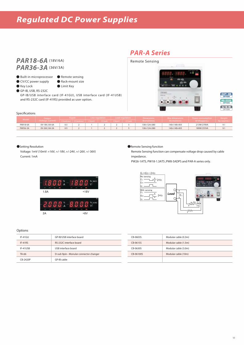
PAR18-6A (18V/6A)
PAR36-3A (36V/3A)
PAR-A Series
Built-in microprocessor Remote sensing CV/CC power supply Rack-mount size Key Lock Limit Key GP-IB, USB, RS-232C GP-IB/USB inter face card (IF-41GU), USB inter face card (IF-41USB)
and RS-232C card (IF-41RS) provided as user option.
Model Output(Voltage, Current)
Ripple Line regulation Load regulation DimensionsWxHxD(mm)
Max dimensionsWxHxD(mm)
Power consumptionW/VA(approx.)
Weightkg (approx.)CV(mVrms) CC(mArms) CV(mV) CC(mA) CV(mV) CC(mA)
PAR18-6A 0V-18V, 0A-6A 0.5 2 1 2 2 5 138×124×380 140×148×403 213W/278VA 9.1
PAR36-3A 0V-36V, 0A-3A 0.5 2 1 2 2 5 138×124×380 140×148×403 189W/255VA 9.1
1.8A +18V
2A +8V
No sensing
E L
IO
r
r
With sensing
EO
S S
+ -
E L
E O
IO
E L
EO
IO
EL=EO-2×IO
2×IO
2×IO Load
Setting Resolution
Voltage: 1mV (10mV: +16V, +/-18V, +/-24V, +/-26V, +/-36V)
Current: 1mA
Remote Sensing function
Remote Sensing function can compensate voltage drop caused by cable
impedance.
PW26-1ATS, PW18-1.3ATS ,PW8-5ADPS and PAR-A series only.
Options
IF-41GU GP-IB/USB interface board CB-0603S Modular cable (0.3m)
IF-41RS RS-232C interface board CB-0615S Modular cable (1.5m)
IF-41USB USB interface board CB-0630S Modular cable (3.0m)
TA-66 D-sub 9pin - Monular connector changer CB-06100S Modular cable (10m)
CB-2420P GP-IB cable
Remote Sensing

Regulated DC Power Supplies
PA-B SeriesPA10-5BPA18-1.2BVT
PA18-2BVTPA18-3BPA18-5BPA36-1.2BVTPA36-2BPA36-3B
PA80-1BPA120-0.6BPA160-0.4BPA250-0.25B PA250-0.42BPA350-0.2BPA600-0.1B
Remote Sensing
Low ripple, low noise
Digital display of voltage and current at the same time
Series/parallel operation
Floating output/voltage remote sensing terminal
External analog control
Monitor output
EIA rack size
Option: GP-IB Adapter (GP-600B and OP-18-PAB)
OptionsGP-600B GP-IB adapter
OP-18-PAB Connection cable between PA-B and GP-600B (1pcs)
OP-20GC Front output terminal guard cap (2pcs)
Model
Output Ripple Line regulation Load regulationDimensions
W×H×D(mm)Max. dimensions
W×H×D(mm)
Power consumption
W/VA(approx.)
Weight kg (approx.)(Voltage,Current)
CV CC CV CC CV CC
mVrms mArms mV mA mV mA
PA10-5B 0V-10V, 0A-5A 0.5 5 1 2 5 5 104 × 124 × 350 106.2 × 144.3 × 368.3 120W/150VA 6.6
PA18-1.2BVT 0V-18V, 0A-1.2A 0.5 1 1 2 2 5 104 × 124 × 270 106.2 × 144.3 × 288.3 50W/60VA 4.7
PA18-2BVT 0V-18V, 0A-2A 0.5 1 1 2 2.5 5 104 × 124 × 270 106.2 × 144.3 × 288.3 75W/100VA 4.7
PA18-3B 0V-18V, 0A-3A 0.5 1 1 2 3 5 104 × 124 × 350 106.2 × 144.3 × 368.3 110W/140VA 6.6
PA18-5B 0V-18V, 0A-5A 0.5 5 1 2 5 5 104 × 124 × 350 106.2 × 144.3 × 368.3 165W/210VA 6.6
PA36-1.2BVT 0V-36V, 0A-1.2A 0.5 1 2 2 2 5 104 × 124 × 270 106.2 × 144.3 × 288.3 80W/105VA 4.7
PA36-2B 0V-36V, 0A-2A 0.5 2 2 2 3 5 104 × 124 × 350 106.2 × 144.3 × 368.3 130W/165VA 6.6
PA36-3B 0V-36V, 0A-3A 0.5 2 2 2 4 5 104 × 124 × 350 106.2 × 144.3 × 368.3 170W/220VA 6.6
PA80-1B 0V-80V, 0A-1A 1 2 5 2 5 5 104 × 124 × 350 106.2 × 144.3 × 368.3 140W/170VA 6.6
PA120-0.6B 0V-120V, 0A-0.6A 1.2 1 7 1 7 5 104 × 124 × 350 106.2 × 144.3 × 368.3 115W/155VA 6.6
PA160-0.4B 0V-160V, 0A-0.4A 1.6 1 8 1 8 5 104 × 124 × 350 106.2 × 144.3 × 368.3 100W/150VA 6.6
PA250-0.25B 0V-250V, 0A-0.25A 2.5 1 15 0.5 15 5 104 × 124 × 350 106.2 × 144.3 × 368.3 105W/140VA 6.6
PA250-0.42B 0V-250V, 0A-0.42A 2.5 1 15 1 15 5 104 × 124 × 350 106.2 × 144.3 × 368.3 150W/220VA 6.6
PA350-0.2B 0V-350V, 0A-0.2A 3.5 1 20 0.5 20 5 104 × 124 × 350 106.2 × 144.3 × 368.3 110W/150VA 6.6
PA600-0.1B 0V-600V, 0A-0.1A 5 1 30 0.5 30 2.5 104 × 124 × 350 106.2 × 144.3 × 368.3 100W/130VA 6.6
GP-600BGP-IB Adapter for PA-B Series Power Supplies
Ripple
CV
GP-IB Adapter for PA-B / PD-AD Series Power Supplies
Specications
GP-IB
Interace function SHA1, AH1, L3, T6, SR1, RL1, PP0, DC1, DT1, C0
Address setting 0 to 30 can be set with the address switch
Service request GP-IB command/parameter errors, OVP operation and alarm functions (OCP, OTP and Power o), CV function, CC function and Output OFF key
Analog Output
Channel Output A&B (CH1), Output C&D (CH2)
Output voltage range 0 to10V
Max. output current 3mA
D/A converter rez 12bit, 0.025%(2.4mV)
Rise Time 100μs or less (10% to 90%, 10kΩ load)
OptionsOP-18-PAB Connection cable between PA-B Series and GP-600B (1pcs)
12

13
DC Electronic Loads
Specications
LSG SeriesLSG-175 (150V/35A/175W)
LSG-350 (150V/70A/350W)
LSG-1050 (150V/210A/1050W)
LSG-2100S (150V/420A/2100W)(Booster for LSG-1050)
Operating Mode : C.V/C.C/C.R/C.P/C.C + C.V/C.R + C.V/C.P + C.C .High Precision, High Resolution (10 A),High Speed Variable Slew Rate
(16A/us).Sequence Function for High Ecient Load Simulations.Parallel Connection of Inputs for Higher Capacity. (With 4 Booster
Units : Max 9.45kW or 4 Master Units)External Channel Control/Monitoring via Analog Control Connector.Program Mode to Create Work Routines for Repetitive Tests.Multiple-Interface : USB 2.0 Device/Host and GP-IB/RS-232C.Adjustable OPP/OCP/OVP Setting.
CP ModeModel LSG-175 LSG-350 LSG-1050Operating RangeH Range 17.5W~175W 35W~350W 105W~1050WM Range 1.75W~17.5W 3.5W~35W 10.5W~105WL Range 0.175W~1.75W 0.35W~3.5W 1.05W~10.5WResolutionH Range 10mW 10mW 100mWM Range 1mW 1mW 10mWL Range 0.1mW 0.1mW 1mWAccuracy of Setting*1
±(0.6 % of set + 1.4 % of f.s.*2)*1 It is not applied for the condition of the parallel operation.*2 M range applies to the full scale of H range.MeterModel LSG-175 LSG-350 LSG-1050VoltmeterH Range 0.00V~150.00V 0.00V~150.00V 0.00V~150.00VL Range 0.000V~15.000V 0.000V~15.000V 0.000V~15.000VAccuracy ±(0.1 % of rdg + 0.1 % of f.s.)AmmeterH, M Range 0.000A~35.000A 0.000A~70.000A 0.00A~210.00AL Range 0.00A~350.00mA 0.00A~700mA 0.0000A~2.1000AAccuracy ±(0.2 % of rdg + 0.3 % of f.s)
Parallel Operation: ±(1.2% of rdg +1.1% of f.s.) WattmeterH, M Range 0.00W~175.00W 0.00W~350.00W 0.00W~1050WL Range(CC/CR/CV)
0.000W~52.500W 0.000W~ 105.000W 0.00W~315.00W
L Range(CP) 0.0000W~ 1.7500W 0.0000W~ 3.5000W 0.000W~ 10.500W
GeneralModel LSG-175 LSG-350 LSG-1050 LSG-2100SInput Range
90VAC~ 132VAC/180VAC~ 250VAC Single-phaseInput Frequency
47~ 63HzPower(max.)
90VA 110VA 190VA 230VADimensionsW 213.8 mm 213.8 mm 427.8 mm 427.7 mmH 124.0 mm 124.0 mm 124.0 mm 127.8 mmD 400.5 mm 400.5 mm 400.5 mm 553.5 mmWeight(Approx.)
7 kg 8 kg 15 kg 17 kg
OptionsGRA-413 Rack Mount Kit (EIA+JIS) for LSG-2100S
GRA-414-E Rack Mount Kit (EIA) for LSG175/350/1050
GRA-414-J Rack Mount Kit (JIS) for LSG175/350/1050
GTL-255 Frame Link Cable
PEL-004 GP-IB Control Board
CC ModeModel LSG-175 LSG-350 LSG-1050Operating RangeH Range 0A~35A 0A~70A 0A~210A
M Range 0A~3.5A 0A~7A 0A~21AL Range 0A~0.35A 0A~0.7A 0A~2.1AResolutionH Range 1mA 2mA 10mAM Range 0.1mA 0.2mA 1mAL Range 0.01mA 0.02mA 0.1mAAccuracy of SettingH, M Range ±(0.2 % of set + 0.1 % of f.s.*1) + Vin*2/500 kΩL Range ±(0.2 % of set + 0.1 % of f.s.) + Vin*2/500 kΩParallel Operating ±(1.2% of set +1.1% of f.s..*3)*1 Full scale of H range*2 Vin: input terminal voltage of electronic load*3 M range applies to the full scale of H rangeCR ModeModel LSG-175 LSG-350 LSG-1050Operating Range*1
H Range 23.3336S~400uS(42.857mΩ~2.5kΩ)
46.6672S~800uS(21.428mΩ~1.25kΩ)
140.0016S~2.4mS(7.1427mΩ~416.6667Ω)
M Range 2.33336S~40uS(428.566mΩ~25kΩ)
4.6667S~80uS(214.28mΩ~12.5kΩ)
14.0001S~242.4uS(71.427mΩ~4.16667kΩ)
L Range 0.233336S~4uS(4.28566Ω~250kΩ)
0.46667S~8uS(2.1428Ω~125kΩ)
1.40001S~24.24uS(714.27mΩ~41.6667kΩ)
ResolutionH Range 400uS 800uS 2.4mSM Range 40uS 80uS 240uSL Range 4uS 8uS 24uSAccuracy of Setting*2
H, M Range ±(0.5 % of set*3 + 0.5 % of f.s.*4) + Vin*5/500 kΩL Range ±(0.5 % of set*3 + 0.5 % of f.s.) + Vin*5/500 kΩ*1 Siemens[S] = Input current[A] / Input voltage[V] = 1 / resistance[Ω]*2 Converted value at the input current. At the input current. It is not applied for the condition of the parallel operation.*3 set = Vin / Rset*4 f.s. = Full scale of High Range*5 Vin = Input terminal voltage of electronic loadCV ModeModel LSG-175 LSG-350 LSG-1050Operating RangeH Range 1.5V~150V 1.5V~150V 1.5V~150VL Range 1.5V~15V 1.5V~15V 1.5V~15VResolutionH Range 10mVL Range 1mVAccuracy of Setting*1
H, L Range ±(0.1 % of set + 0.1 % of f.s.)*1 At the sensing point during remote sensing under the operating range of the input voltage. It is also applied for the condition of the parallel operation.
10mV 10mV1mV 1mV
High Capacity Electronic Load (Max. 9.45kW)

14
DC Electronic Loads
LSA Series
LSA-165 LSA-165V1 LSA-330 LSA-1000 Compact size which is 1/3-rack-size for 165W model and 330W
model. Reduce the bulk ratio to 60% of that of the conventional
company products.
Full-color 3.5 inch LCD provides high operability and visibility.
10μA minimum resolution for current setting (LSA-165 L range).
Input
Model LSA-165 LSA-330 LSA-1000
Input power
H 0W - 165W 0W - 330W 0W - 1000W
M 0W - 16.5W 0W - 33W 0W - 100W
L 0W - 1.65W 0W - 3.3W 0W - 10W
Input voltage VCR 0V - 150V
except CR 1V - 150V
Input current
Rear input terminal
0A - 33A 0A - 66A 0A - 200A
Front input terminal 0A - 66A
Input terminal formFront Screw terminal
Rear Cupper bus bar
Constant current mode(CC)
Model LSA-165 LSA-330 LSA-1000
Setting range
H 0A - 33A 0A - 66A 0A - 200A
M 0A - 3.3A 0A - 6.6A 0A - 20A
L 0mA - 330mA 0mA - 660mA 0mA - 2000mA
Setting resolution
H 1mA 2mA 6mA
M 0.1mA 0.2mA 0.6mA
L 10µA 20µA 60µA
Maximum power
H 165W 330W 1000W
M 16.5W 33W 100W
L 1.65W 3.3W 10W
Ripple noise(ms)In the rage of 10Hz to 1MHz
H 10mA 15mA 30mA
M 5mA 5mA 10mA
L 1mA 1mA 3mA
Stability (long term drift) ±0.1% of fs typ
Temperature factor 100ppm/°C
Constant resistance mode(CR)
Model LSA-165 LSA-330 LSA-1000
Setting resistance
H OPEN, 1.81kΩ - 30.3m Ω
OPEN, 909Ω - 15.1m Ω
OPEN, 303Ω - 5.05m Ω
M OPEN, 18.1kΩ - 303m Ω
OPEN, 9.09Ω - 151m Ω
OPEN, 3.03kΩ - 50.5m Ω
L OPEN, 181kΩ - 3.03 Ω
OPEN, 90.9kΩ - 1.51 Ω
OPEN, 30.3kΩ - 505m Ω
Setting resolution
H 0.55mS 1.1mS 3.3mS
M 55µS 0.11mS 0.33mS
L 5.5µS 11µS 33µS
Ripple noise(ms)In the rage of 10Hz to 1MHz
H 10mA 15mA 30mA
M 5mA 5mA 10mA
L 1mA 1mA 3mA
Stability (long term drift) ±0.1% of fs typ
Temperature factor 1000ppm/°C
Constant power mode(CP)
Model LSA-165 LSA-330 LSA-1000
Setting power
H 0W - 165W 0W - 330W 0W - 1000W
M 0W - 16.5W 0W - 33W 0W - 100W
L 0W - 1.65W 0W - 3.3W 0W - 10W
Setting resolution
H 10mW 20mW 100mW
M 1mW 2mW 10mW
L 0.1mW 0.2mW 1mW
Ripple noise(ms)In the rage of 10Hz to 1MHz
H 10mA 15mA 30mA
M 5mA 5mA 10mA
L 1mA 1mA 3mA
Stability (long term drift) ±0.2% of fs typ
Temperature factor 1000ppm/°C
Constant voltage(CV+CC/CV+CR) mode
Model LSA-165 LSA-330 LSA-1000
Setting voltageH 0.1V - 150V
L 0.1V - 15V
Setting resolutionH 10mV
L 1mV
Minimum current for operating 1% of fs current
Stability (long term drift) ±0.2% of fs typ
Input current uctuation 10mV
Temperature factor 1000ppm/°C
CC/CR/CP/CC+CV/CR+CV mode are selectable.
High-speed response for 10μsec. Switching function is available
(CC, CR, CP mode).
External voltage / resistance control function is available.
Maximum 5-unit-parallel master-slave operation is available.
Sequence control provides branch on condition.
Option: GP-IB, USB and RS-232C are in one slot-in option board
IF-80GUR.Recommend to use GP-IB or RS-232C if you use LSA
series at noisy condition.
LCD Display
“Direct keys” are located on the right side display makes easy to use.
Unique rotary encoder. You can rotate with your nger tip and pen tip, too.
End pointStart point
Step No.
Ramp Sine
Pulse
Except LSA-165V1

15
DC Electronic Loads
Specications
LW Series
Multi-channel & individual control Each channel is isolated and can be controlled individually. Low cost High performance The CC, CR, CV, CP modes are standard.
4 points presetting 4 sets of frequently used value can be preset. Key lock Key lock function provides to hold all setting values. Various remote controls (user option) It is possible to add the interface function of GP-IB or USB after
purchasing as user option. Front input terminal (A type only) Maximum input current is 30A. Maximum 12 channel in full rack size
Front terminal model
Multi ChannelLW75-151QV7A (150V/15A/75W 4Channel)
LW75-151DV7A (150V/15A/75W 2Channel)
LW151-151DV7A (150V/30A/150W 2Channel)
LW301-151SV7ALW301-151SV7B
(150V/60A/300W 1Channel)
(150V/60A/300W 1Channel)
OptionsIF-50GP GP-IB control board
IF-50USB USB control board
Model Input Channel
Input Constant Current Constant Resistance ConstantPower
Constant PowerInput
TerminalVoltage Current Power L range H range L range H range L range H range
V A W A A Ω Ω V W W
LW75-151QV7A 4ch
1 - 150
0 - 15 0 - 75 0 - 2.5 0 - 15 0.6 - 6k 0.1 - 1k
0.00 - 150
0.625 - 12.5 3.75 - 75 Front/Rear
LW75-151DV7A 2ch 0 - 15 0 - 75 0 - 2.5 0 - 15 0.6 - 6k 0.1 - 1k 0.625 - 12.5 3.75 - 75 Front/Rear
LW151-151DV7A 2ch 0 - 30 0 - 150 0 - 5 0 - 30 0.3 - 3k 0.05 - 500 1.25 - 25 7.5 - 150 Front/Rear
LW301-151SV7A 1ch 0 - 30 0 - 300 0 - 10 0 - 30 0.15 - 1.5k 0.025 - 250 2.5 - 50 15 - 300 Front/Rear
LW301-151SV7B 1ch 0 - 60 0 - 300 0 - 10 0 - 60 0.15 - 1.5k 0.025 - 250 2.5 - 50 15 - 300 Rear Only

Application Software "ESCAS"
S-PL10Charge/Discharge Test with using regulated DC power supplies
and Electronic Loads with ease
This software is a sequence program creator software for regulated DC power
supplies and electric loads and most suitable for charge/discharge testing for
secondary cells. Anyone can conduct setup, test and analysis easily.
Language characters are selectable, Japanese, English and (Simplied /
Traditional) Chinese. (Descriptions can be displayed with "HELP" window
written in Japanese or English only.)
Max. 12ch Charge/Discharge systemThis software is compliant with 4 series of
regulated DC power supplies and 2 series of electronic loads, and can control
max. 12 sets of power supply and electronic load. (each power supplies and
electronic loads must be same model. possible to control master-slave units.)
TEST MODE functionA measuring sampling rate is changed depend on a
number of channels or models of power supplies and electronic load. TEST
MODE can check suitable sampling rate before testing.
Creating sequence patterns with ease
It is easy to create new sequence patterns, to edit saved patterns, and to copy
saved patterns.
CSV test data, Graphical analyzing
All test data is saved as csv text data. Graphical analyzing function is available.
System Requirements
Microsoft Windows 7 SP1 or higher (32bit/64bit)
Test mode
Sequence pattern creator/editor mode
Graphical analyzing mode
LW Series(Page 14)
PSF-L Series, PSF-H Series(Page 5-6)
PS-A Series(Page 8)
PU Series
PDS-A Series(Page 7)
LSA Series(Page 12)
ESCAS
16

High rez Constant Voltage Regulated DC Power Supplies Unit
BATTERY CELL SIMULATOR (for BCM)Multi ChannelM-6150 (5V/300mA 12ch, GP-IB)
M-6151 (5V/300mA 14ch, GP-IB)
Specications
Output
Output channels 12ch/unit (M-6150), 14ch/unit (M-6151)
Output voltage DC 0 to 5V /ch
Output current DC 300mA /ch
Operating mode CV (Constant voltage) mode only
Output terminals M3 screw terminals (on rear panel)
Voltage regulation characteristics
Output stability(at output terminal) Line regulation within ±(0.01% of setting + 2mV)
Load regulation within ±(0.01% of setting + 3mV)
Ripple/Noise within 1mVrms (at output 5V)
GP-IB
Setting voltage Cycle 1sec (for setting all cahnnels)
Resolution 0.1mV
Accuracy ±1mV
Measurement Cycle 1sec (for reading all cahnnels)
Voltage resolution 0.1mV
Voltage accuracy ±1mV
Current resolution 10μA
Current accuracy ±(0.2% of F.S. + 0.2% of reading)
Others
Power requirement 100V±10% AC, 50/60Hz, Single phase
Power consumption 210VA
Groundable voltage DC 600V
Dimentions 430mm(W) x 150mm(H) x 500mm(D)
Weight Approx. 17kg (including rack mount cramps)
17

18
1GS/s Digital Storage Oscilloscopes
DCS-1000B Series
DCS-1074B (1GS/s 4ch 70MHz )
DCS-1104B (1GS/s 4ch 100MHz )
DCS-1072B (1GS/s 2ch 70MHz )
DCS-1054B (1GS/s 4ch 50MHz )
DCS-1102B (1GS/s 2ch 100MHz )
100MHz/70MHz/50MHz Digital Storage Oscilloscope Waveform update rate up to 50,000wfms/s
256 gradstion 7inches WVGA display
10M memory depth per channel independently 1M FFT mathematical sampling analysis mode
Zoom In/Play and Pause Function Diversied Trigger Functions X-Y Mode Display Go/NoGo Function Data Log Function Digital Filter Function 36 Measurement Parameter Selections
Specications
DCS-1054B DCS-1072B DCS-1074B DCS-1102B DCS-1104B
Vertical
Channels DCS-1xx4B : 4ch , DCS-1XX2B : 2ch+EXT
Bandwidth DC~ 50MHz DC~ 70MHz DC~ 70MHz DC~ 100MHz DC~ 100MHz
Resolution 8 bit @1MΩ: 1mV~10V
Input Impedance 1MΩ // 16pF
DC Gain Accuracy 1mV: ±4% full scale, >2mV: ±3% full scale
Waveform Signal Process +, -, ×, ÷, FFT, FFTrms, User Dened ExpressionFFT: Spectral magnitude. Set FFT Vertical Scale to Linear RMS or dBV RMS, and FFT Window to Rectangular, Hamming, Hanning, or Blackman-Harris
Trigger
Source CH1, CH2, CH3*, CH4*, Line, EXT** *four channel models only. **two channel models only.
Trigger Type Edge, Pulse Width(Glitch), Video, Pulse Runt, Rise & Fall(Slope), Timeout, Alternate, Event-Delay(1~65535 events), Time-Delay(Duration, 4nS~10S), Bus
Coupling AC, DC, LF rej., Hf rej., Noise rej.
Sensitivity 1div
External Trigger
Range ±15V
Sensitivity DC ~ 100MHz Approx. 100mV
Horizontal
Time base Range 5ns/div ~ 100s/div (1-2-5 increments) ROLL: 100ms/div ~ 100s/div
Pre-trigger 10 div maximum
Post-trigger 2,000,000 div maximum.
Real Time Sample Rate 1GSa/s max.
Record Length Max. 10Mpts
Acquisition Mode Normal, Average, Peak Detect, Single
Peak Detection 2nS (typical)
Average selectable from 2 to 256
X-Y Mode
X-Axis Input Channel 1; Channel 3* *four channel models only
Y-Axis Input Channel 2; Channel 4* *four channel models only
Phase Shift ±3° at 100kHz
Cursors and Measurement
Cursors Amplitude, Time, Gating available; Unit: Seconds(s), Hz(1/s), Phase(degree), Ration(%)
Automatic Measurement 36 sets: Pk-Pk, Max, Min, Amplitude, High, Low, Mean, Cycle Mean, RMS, Cycle RMS, Area, Cycle Area, ROVShoot, FOVShoot, RPREShoot, FPREShoot, Frequency, Period, RiseTime, FallTime, +Width, -Width, Duty Cycle, +Pulses, -Pulses, +Edges, -Edges, FRR, FRF, FFR, FFF, LRR, LRF, LFR, LFF, Phase
Control Panel Function
Autoset Single-button, automatic setup of all channels for vertical, horizontal and trigger systems, with undo Autoset
Save Setup 20set
Save Waveform 24set
Display
TFT LCD Type 7” TFT WVGA color display 800 horizontal × 480 vertical pixels (WVGA)
Waveform Update Rate 50,000 waveforms per second, maximum
Interface
USB Port USB 2.0 High-speed host port X1, USB High-speed 2.0 device port X1
Ethernet Port (LAN) RJ-45 connector, 10/100Mbps with HP Auto-MDIX (4ch Model Only)
General
Dimensions 384mmX208mmX127.3mm
Weight 2.8kg
Power Source 100V~240V AC, 50Hz~60Hz, Auto selection, Power consumption: 30 Watts
7” TFT WVGA color display

1GS/s Digital Storage Oscilloscopes
200MHz/100MHz/70MHz Digital Storage Oscilloscope
Waveform update rate up to 120,000wfms/s
256 gradation 8inches WVGA display
10M memory depth per channel independently
1M FFT mathematical sampling analysis mode
Zoom In/Play and Pause Function
Diversied Trigger Functions
X-Y Mode Display
Go-NoGo function
Data Log Function
Digital Filter Function
36 Measurement Parameter Selections
DCS-2104E (1GS/s 4ch 100MHz )
DCS-2204E (1GS/s 4ch 200MHz )
DCS-2072E (1GS/s 2ch 70MHz )
DCS-2074E (1GS/s 4ch 70MHz )
DCS-2102E (1GS/s 2ch 100MHz )
DCS-2202E (1GS/s 2ch 200MHz )
SpecificationsDCS-2072E DCS-2074E DCS-2102E DCS-2104E DCS-2202E DCS-2204E
Vertical
Channels DCS-2xx4E : 4ch , DCS-2XX2E : 2ch+EXT
Bandwidth DC~ 70MHz DC~ 100MHz DC~ 200MHz
Resolution 8 bits : 1mV~10V
Input Impedance 1MΩ // 16pF
DC Gain Accuracy 1mV: ±5% full scale, >2mV: ±3% full scale
Waveform Signal Process +, -, ×, ÷, FFT, FFTrms, User Dened ExpressionFFT: Spectral magnitude. Set FFT Vertical Scale to Linear RMS or dBV RMS, and FFT Window to Rectangular, Hamming, Hanning, or Blackman-Harris
Trigger
Source CH1, CH2, CH3*, CH4*, Line, EXT** *four channel models only. **two channel models only.
Trigger Type Edge, Pulse Width(Glitch), Video, Pulse Runt, Rise & Fall(Slope), Timeout, Alternate, Event-Delay(1~65535 events), Time-Delay(Duration, 4nS~10S), Bus
Coupling AC, DC, LF rej., Hf rej., Noise rej.
Sensitivity 1div
External Trigger
Range ±15V
Sensitivity DC ~ 100MHz Approx. 100mV 100MHz ~ 200MHz Approx. 150mV
Horizontal
Time base Range 1ns/div ~ 100s/div (1-2-5 increments) ROLL: 100ms/div ~ 100s/div
Pre-trigger 10 div maximum
Post-trigger 2,000,000 div maximum.
Real Time Sample Rate 1GSa/s max.
Record Length Max. 10Mpts
Acquisition Mode Normal, Average, Peak Detect, Single
Peak Detection 2nS (typical)
Average selectable from 2 to 256
X-Y Mode
X-Axis Input Channel 1; Channel 3* *four channel models only
Y-Axis Input Channel 2; Channel 4* *four channel models only
Phase Shift ±3° at 100kHz
Cursors and Measurement
Cursors Amplitude, Time, Gating available; Unit: Seconds(s), Hz(1/s), Phase(degree), Ration(%)
Automatic Measurement 36 sets: Pk-Pk, Max, Min, Amplitude, High, Low, Mean, Cycle Mean, RMS, Cycle RMS, Area, Cycle Area, ROVShoot, FOVShoot, RPREShoot, FPREShoot, Frequency, Period, RiseTime, FallTime, +Width, -Width, Duty Cycle, +Pulses, -Pulses, +Edges, -Edges, FRR, FRF, FFR, FFF, LRR, LRF, LFR, LFF, Phase
Control Panel Function
Autoset Single-button, automatic setup of all channels for vertical, horizontal and trigger systems, with undo Autoset
Save Setup 20set
Save Waveform 24set
Display
TFT LCD Type 8” TFT WVGA color display 800 horizontal × 480 vertical pixels (WVGA)
Waveform Update Rate 120,000 waveforms per second, maximum
Interface
USB Port USB 2.0 High-speed host port X1, USB High-speed 2.0 device port X1
Ethernet Port (LAN) RJ-45 connector, 10/100Mbps with HP Auto-MDIX
General
Dimensions 384mm X 208mm X 127.3mm
Weight Approx 2.8kg
Power Source 100V~240V AC, 48Hz~63Hz, Auto selection, Power consumption 30Watts
120,000wfms/s 500wfms/s
DCS-2000E Series8” TFT WVGA color display
19

20
DCS-4605 (250MS/s 2ch 50MHz)
250MS/s Digital Storage Oscilloscopes
Color TFT LCD
Automatic measurement functions
19 kinds of automatic measurement functions are available and ve
parameters can be displayed on the LCD display at same time.
Automatic calculation functions
Versatile calculation ( +, -, x, FFT ) functions are available.
Built-in memory
The DCS-4605 can memories front panel setting and wave forms
data by themselves using the memory.
Clear display
The DCS-4605 have a broad outlook 5.6 inch color LCD display
(TFT) and LED back light.
Support voltage and current probes
Enable to set measuring scales of voltage / current (vertical axis) at
from x0.1 to x2000 (1-2-5 steps) according to probes.
Various trigger functions
Edge trigger, Video trigger and Pulse trigger functions are
available.
An "educational mode" function can be used in order to prevent a
student from using an automatic calculation function.
Application software; FreeWave
The software enables to control the DCS-4605 by PC (through USB).
It can display wave forms on PC display in real time and save wave
forms data as not only still picture but also motion picture by PC.
Go-NoGo function
Data logger function (with using USB ush drive)
Model DCS-4605
Vertical axisSensibility 2mV/div to 10V/div (1-2-5 steps)
Accuracy ±(3% × [Readout] + 0.1div + 1mV)
Bandwidth(-3dB) DC(AC)Coupling DC (10Hz) to 50MHz
Rise time 7.0ns max
Input impedance 1MΩ±2%, Approx.15pF
Maximum input voltage 300V (DC + AC peak ), Installation Category Ⅱ20MHz bandwidth (-3dB) function Available
TriggerSources CH1,CH2, LINE, EXT
Modes AUTO, NORMAL, SINGLE, TV(Video ), Edge, Pulse Width, Forcing
Coupling AC, DC, Low/High Frequency rejection, Noise rejection
Trigger sensibility 0.5div (5mV min.) DC to 25MHz
Ext. Trigger sensibility 1.5div (5mV min.) 25MHz to 50MHz
Horizontal axisRange 1ns/div to 50s/div, 1-2-5steps (50ms/div to 50s/div at Roll mode)
Modes
Accuracy ±0.01%
Delay rangePre-trigger 10 div max.
Post-trigger 1000div
Signal Acquisition System
Sample rateReal-time 250MS/s max. (1ch)
Equivalent 25GSs/s max.
Vertical resolution 8bits, 25levels/div
Record length 4000 points
Acquisition modes Normal, Peak Detect, Average
Peak detection 10ns (500ns/div to 50s/div)
Average 2, 4, 8, 16, 32, 64, 128, 256
Cursors and Measurement
Automatic measurement functions
Vertical axis Peak-to-peak, Max, Min, Amp, High, Low, Average, Rms Upper/Lower overshoot, Upper/Lower preshoot
Horizontal axis Frequency, Period, Rise time, Fall time, Positive pulse width, Negative pulse width, Duty cycle
Cursors measurement Voltage / Time difference between cursors (V, ⊿T, 1/⊿T)
Frequency counter Resolution : six digits, Accuracy : ±2%(cannot measure below two Hz)
Interfaces
USB Host /USB Slave* USB Flash Drive Max 32GB / USB 2.0 Full speed(USB-CDC)
GeneralPower requirements 100V to 240V AC, 47Hz to 63Hz
Power consumption 18Watts, 40VA max
Dimensions 341.5(W)×162.3(H)×159(D)mm
Weight Approx. 2.5kg
Accessories Probe x2, AC power cable, CD-ROM ( instruction manual, APP software: FreeWave)
Specifications
*Not support via USB3.0 or above

21
500VA and AC Test Capacity 240 x 64 Ice Blue Dot Matrix LCD
Manual/Auto Mode
Function Key for Quick Selecting
High Intensity Flash for Caution & Status Indication Safety Interlock Function Zero Crossing Turn-on Operation Controllable Ramp-up Time
STW-9900/9800 Series
True RMS Current Measurement High Resolution : 1μA for Measuring Current, 2V for Setting Voltage
PWM Switching Amplier to Enhance the Power Eciency and Reliable Testing Max. 100 Memory Block for Test Condition (Step) Setting. And Each Step
can be Named Individually
Remote Terminal on the Front Panel for“Start”and“Stop” Control by External Interface: RS-232C, USB Devise, Signal I/O and GP-IB (Option: OPT.1)
500VA and 200VA AC Test Capacity
STW-9903 (AC 500VA) /STW-9803 (AC 200VA)
STW-9901 (AC 500VA) /STW-9801 (AC 200VA)
STW-9904 (AC 500VA)
STW-9902 (AC 500VA) /STW-9802 (AC 200VA)
Electrical Safety Testers
EnvironmentRange Temperature HumidityWarranty 15˚C ~ 35˚C ≤70% (No condensation)Operation 0˚C ~ 40˚C ≤70% (No condensation)Storage -10˚C ~ 70˚C ≤85% (No condensation)Installation Location Indoors at an amplitude of up to 2000m.AC Withstanding Voltage STW-9801/9802/9803 STW-9901/9902/9903/9904Output Voltage Range 0.100kV~ 5.000kV Output Voltage Resolution 2V/stepOutput Voltage Accuracy ± (1% of setting +5V) with no loadMaximum Rated Load(Table1) 200 VA (5kV/100mA) 500 VA (5kV/100mA)
Maximum Rated Current 10mA(0.1kV≤V≤0.5kV)40mA(0.5kV<V≤5kV)
10mA(0.1kV≤V≤0.5kV)100mA(0.5kV<V≤5kV)
Output Voltage Waveform Sine waveFrequency 50 Hz / 60 HzVoltage Regulation ± 1% +5V [Maximum rated load → no load]Voltmeter Accuracy ± (1% of reading+ 5V)Current Measurement Range 0.001mA~40.0mA 0.001mA~100.0mA
Current Best Resolution0.001mA(0.001mA~0.999mA)0.01mA(01.00mA~09.99mA)0.1mA(010.0~040.0mA)
0.001mA(0.001mA~1.100mA)0.01mA(01.11mA~11.00mA)0.1mA(011.1~100.0mA)
Current Measurement Accuracy ± (1.5% of rdg + 30 counts) HI SET<1.00mA± (1.5% of rdg + 3 counts) HI SET≥1.00mA
± (1.5% of rdg + 30 counts) HI SET<1.11mA± (1.5% of rdg + 3 counts) HI SET≥1.11mA
Window Comparator Method YesARC DETECT YesRise-time Control Function YesRAMP (Ramp Time) 0.1s~999.9sTIMER (Test Time) OFF*, 0.5s~999.9sGND ON/OFF* The timer can only be turned off under special MANU mode (MANU=***-000)DC Withstanding Voltage STW-9802/9803 STW-9902/9803/9804Output Voltage Range 0.100kV~ 6.000kVOutput Voltage Resolution 2VOutput Voltage Accuracy ± (1% of setting +5V) with no loadMaximum Rated Load (Table1) 50W (5kV/10mA) 100W (5kV/20mA)
Maximum Rated Current 2mA (0.1kV≤V≤0.5kV)10mA (0.5kV<V≤6kV)
2mA (0.1kV≤V≤0.5kV)20mA (0.5kV<V≤6kV)
Voltmeter Accuracy ± (1% of reading+ 5V)Voltage Regulation ± 1% +5V [Maximum rated load → no load]Current Measurement Range 0.001mA~010.0mA 0.001mA~020.0mA
Current Best Resolution0.001mA(0.001mA~0.999mA)0.01mA(01.00mA~9.99mA)0.1mA(010.0mA)
0.001mA(0.001mA~1.100mA)0.01mA(01.11mA~11.00mA)0.1mA(011.0mA~020.0mA)
Current Measurement Accuracy ± (1.5% of rdg + 30 counts) HI SET <1.00mA± (1.5% of rdg + 3 counts) HI SET ≥1.00mA
± (1.5% of rdg + 30 counts) HI SET <1.11mA± (1.5% of rdg + 3 counts) HI SET ≥1.11mA
Window Comparator Method YesARC DETECT YesRise-time Control Function YesRAMP (Ramp Time) 0.1s~999.9sTIMER (Test Time) OFF*, 0.5s~999.9sGND ON/OFF* The timer can only be turned off under special MANU mode (MANU=***-000)
Insulation Resistance Test STW-9803/9903/9904Output Voltage 50V~1000VOutput Voltage Resolution 50VOutput Voltage Accuracy (1% of setting+5V) with no load
Resistance Measurement Range (STW-9803)
1MΩ~ 9500MΩ Test Voltage Measurement Range Accuracy
50V≤V≤450V 0.001GΩ ~0.050GΩ0.051GΩ ~2.000GΩ
±(5% of reading +1 count)±(10% of reading +1 count)
500V≤V≤1000V 0.001GΩ ~0.500GΩ0.501GΩ ~9.500GΩ
±(5% of reading +1 count)±(10% of reading +1 count)
Resistance Measurement Range (STW-9903/ 9904)
1MΩ~ 50GΩ Test Voltage Measurement Range Accuracy
50V≤V≤450V 0.001GΩ ~0.050GΩ0.051GΩ ~2.000GΩ
±(5% of reading +1 count)±(10% of reading +1 count)
500V≤V≤1000V0.001GΩ ~0.500GΩ0.501GΩ ~9.999GΩ10.00GΩ ~50.00GΩ
±(5% of reading +1 count)±(10% of reading +1 count)±(15% of reading +1 count)
Output Impedance 600kΩWindow Comparator Method YesRise-time Control Function YesRAMP (Ramp Time) 0.1s~999.9sTIMER (Test Time) 1s~999.9sGND OFFGround Bond Test STW-9904Output Current Range 03.00A~32.00A
Output Current Accuracy ± (1% of reading +0.2A) when 3A ≤ I ≤ 8A± (1% of reading +0.05A) when 8A < I ≤ 32A
Output Current Resolution 0.01AFrequency 50Hz/60Hz selectableOhmmeter Measurement Accuracy ± (1% of reading +2mΩ)
Ohmmeter Measurement Range 10mΩ~650.0mΩ (depending on output current)Test Voltage Max. 6V(AC)open - circuitOhmmeter Measurement Resolution 0.1mΩ
Windows Comparator Method YesTIMER (Test Time) 0.5s~999.9sGND OFFInterfaceREMOTE (Remote terminal) YesSIGNAL IO YesRS-232C YesUSB (Device) YesGPIB Yes (OPTION)GeneralDISPLAY 240 x 64 dot matrix LED back light LCDMEMORY AUTO/MANU mode 100 memory blocks totalPOWER SOURCE AC100V/120V/220V/230V ±10% 50Hz/60Hz
ACCESSORIES Power cord x1,User Manual x1 (CD),GHT-114x1(GTL-115x1 for STW-9904)
DIMENSIONS & WEIGHTSTW-9801/9802/9803:Approx. 322(W) x 148(H) x 452(D)mm(Max) 24kg(Max)STW-9901/9902/9903:Approx. 322(W) x 148(H) x 482(D)mm(Max) 24kg(Max)STW-9904: Approx. 322(W) x 148(H) x 594(D) mm (Max.) 27kg(Max)
22
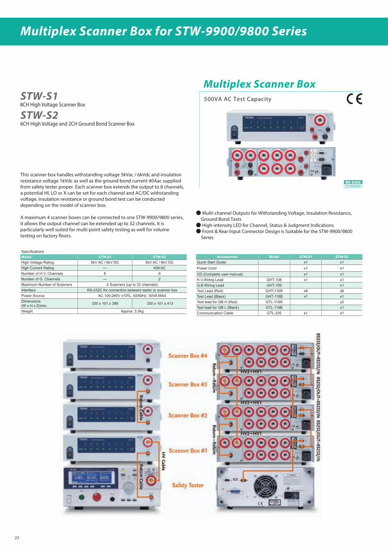
Multiplex Scanner Box 500VA AC Test Capacity
STW-S1
STW-S2
Multiplex Scanner Box for STW-9900/9800 Series
Multi-channel Outputs for Withstanding Voltage, Insulation Resistance, Ground Bond Tests
High-intensity LED for Channel, Status & Judgment Indications Front & Rear Input Connector Design is Suitable for the STW-9900/9800
Series
This scanner box handles withstanding voltage 5kVac / 6kVdc and insulation resistance voltage 1kVdc as well as the ground bond current 40Aac supplied from safety tester proper. Each scanner box extends the output to 8 channels, a potential HI, LO or X can be set for each channel and AC/DC withstanding voltage, insulation resistance or ground bond test can be conducted depending on the model of scanner box.
A maximum 4 scanner boxes can be connected to one STW-9900/9800 series, it allows the output channel can be extended up to 32 channels. It is particularly well suited for multi-point safety testing as well for volume testing on factory oors.
SpecificationsModel STW-S1 STW-S2High Voltage Rating 5kV AC / 6kV DC 5kV AC / 6kV DCHigh Current Rating --- 40A ACNumber of H.V. Channels 8 6Number of G. Channels --- 2Maximum Number of Scanners 4 Scanners (up to 32 channels)Interface RS-232C for connection between tester or scanner boxPower Source AC 100-240V ±10%, 50/60Hz 50VA MAXDimensions (W x H x D)mm 330 x 101 x 399 330 x 101 x 413
Weight Approx. 5.5kg
Accessories Model STW-S1 STW-S2Quick Start Guide x1 x1Power Cord x1 x1CD (Complete user manual) x1 x1H.V.Wiring Lead GHT-108 x1 x1G.B Wiring Lead GHT-109 x1Test Lead (Red) GHT-116R x8 x6Test Lead (Black) GHT-116B x1 x1Test lead for GB H (Red) GTL-116R x2Test lead for GB L (Black) GTL-116B x1Communication Cable GTL-235 x1 x1

Color Pattern Generators
CG-971 Color pattern GeneratorAnalog video signal/Audio signal output Conformity with NTSC,PAL,PAL-M and TNSC-4.43 Selectable sync level Each staircase level in step pattern settable by voltage Natural image and Monoscope pattern output Max. 24 pattern installation Auto sequence mode RS-232C, and Digital IF ( T TL ) for remote control Half rack size of 19 inch EIA 2U
NTSC / PAL
Image
Basic patterns Raster, window, cross hatch, dot, cross & dot, checker, stripes (vertical / horizontal), step (division input / level input), character, color bar (split / SPPTE), and monoscope
Natural Image data 712 X 574 dots, 1-,4-,8-,24- and 32-bit color BMP le format (Incompatible with RLE compression.)
Output functions Reversing, luminance component ON/OFF and chrominance component ON/OFF functions
Image formats NTSC-M, NTSC-J, NTSC-4.43, PAL-B/D/G/H/I, PAL-M
Video output (CVBS)75Ω, BNC connector.1.0V(p-p) : NTSC-M/J/4.43, PAL-M (0.714+0.286V(p-p)), PAL-B/D/G/H/I (0.7+0.3V(p-p))Setup level : 7.5% NTSC-M, and PAL-M only, 0% Others
S connector ( Y/C)Y+S (SYNC to 100% white) : 1.0V(p-p) ( Dierences according to the formats are equivalent to those of CVBS)Accuracy = larger value of ±5% and ±20mV, 75ΩC ( burst ) : 300mV(p-p), Accuracy =±5%, 75Ω
RGB output (Not for PC use) 700mV(p-p), Accuracy = ±5%, 75Ω BNC connector
SYNC outputFront : V-SYNC/C-SYNC switching, T TL output, BNC connector, polarity may be switched by system le settingRear H.V sync output : T TL output, BNC connector, polarity may be changed by system le setting
Audio output
Audio level 0.1V to 2.0V (Rand L may be set independently in 0.1V steps ), Accuracy = ±10% ( with no termination at full scale )
Audio frequency 100Hz to 20kHz ( R and L may be set independently in 100Hz steps ), Accuracy = ±10% ( open end at full scale )
Outpt connectors RCA pin jacks, 2-channel ( stereo ), unbalance, 600Ω
Others
Sequence 24 steps max. May be changed up to maximum of 60 seconds in units of 1 second per step. Automatic and step operation are selectable.
Compatible CF cardsFAT12, FAT16 and FAT32 only. Not compatible with NTFS. Capacity is 2GB or less.* We use 2GB or smaller-capacity CF cards made by SAN DISK CO., LTD. To check operations. It will not warrant the performance if the user uses other CF cards.
LCD display 2-line, 40-digit LCD ( with LED backlight )
External control RS-232C and digital interface ( TTL level, parallel ) are selectable.
AccessoriesInstruction manual, power cord, and application disc * Setup application software : Compatible with MS Windows 98/ME and Windows 2000/XP/VISTA* CF card is not included as standard equipment
Power source AC 100V to 240V, 50Hz or 60Hz
Temp. / humid rangeOperating 0°C to 40°C RH85% or less (No dew condensations)
Spec. 10°C to 35°C RH85% or less
Dimension and Weight210(W) × 98( H ) × 315(D ) mmApprox. 2.5kg
Raster(Red, Green, blue, Yellow,Magenta, Cyan, White20/50/75/100%)
Window Cross hatch Dot Cross & Dot Checker Stripes(Vertical/Horizontal)
Step(Division/Level input)
Ramp Character Color bar(75/100% sprit)
Monoscope Natural image data
Examples of signal patterns
CG-971
Color bar (SMPTE)
23

24
2ch Arbitrary Function Generator
FGX-2220 2ch Arbitrary Function Generator
FGX-222020MHz 2ch Arbitrary Function Generator
DDS Function Generator series
1μHz high frequency resolution maintained at full range
20ppm frequency stability
Arbitrary Waveform Capability
Sine, Square, Ramp, Pulse, Noise, standard waveforms
Internal and external LIN/LOG sweep with marker output
Int/Ext AM, FM, PM, FSK, SUM modulation
Burst function with internal and external triggers without marker
output
Store/recall 10 groups of setting memories
Output overload protection
USB interface as standard
3.5 inch Color TFT LCD (320 X 240) graphical user interface
SpecicationsCH1 CH2
Waveforms Sine, Square, Ramp, Pulse, Noise, ARB
Arbitrary Functions
Sample Rate 120 MSa/s
Repetition Rate 60 MHz
Waveform Length 4k points
Amplitude Resolution 10 bits
Non-Volatile Memory 4k points
Frequency Characteristics
Range Sine, Square 1uHz to 20MHz
Ramp 1MHz
Resolution 1uHz
Accuracy Stability ±20 ppm
Aging ±1 ppm, per 1 year
Tolerance ≤1 mHz
Output Characteristics
Amplitude Range 1mVpp to 10 Vpp (into 50Ω), 2mVpp to 20 Vpp (open-circuit)
Accuracy ±2% of setting ±1 mVpp (at 1 kHz)
Resolution 1mV or 3 digits
Flatness ±1% (0.1dB) ≤100kHz, ±3% (0.3 dB) ≤5MHz, ±5% (0.4 dB) ≤12MHz, ±10%(0.9dB) ≤20MHz (sine wave relative to 1kHz)
Units Vpp, Vrms, dBm
Oset Range ±5 Vpk ac +dc (into 50Ω), ±10Vpk ac +dc (Open circuit)
Accuracy 2% of setting + 10mV+ 0.5% of amplitude
Waveform Output Impedance 50Ω typical (xed), > 10MΩ (output disabled)
Protection Short-circuit protected, Overload relay automatically disables main output
Sine wave Characteristics
Harmonic distortion ≦ -55 dBc DC to 200kHz, Ampl≧ 0.1Vpp, ≦ 0 dBc 200kHz to 1MHz, Ampl ⋎ 0.1Vpp, ≦ 35 dBc 1MHz to 5MHz, Ampl ⋎ 0.1Vpp, ≦ -30 dBc 5MHz to 20MHz, Ampl ⋎ 0.1Vpp
Square wave Characteristics
Rise/Fall Time ≤25ns at maximum output. (into 50 Ω load)
Overshoot 5%
Asymmetry 1% of period +5 ns
Variable Duty Cycle 1.0% to 99.0% ≤100kHz, 10% to 90% ≤ 1MHz, 50% ≤ 20MHz
Ramp Characteristics
Linearity < 0.1% of peak output
Variable Symmetry 0% to 100% (0.1% Resolution)
Pulse Characteristics
Period 40ns to 2000s
Pulse Width 20ns to 1999.9s
Overshoot <5%
Jitter 20ppm +10ns
Modulation
AM Modulation, FM Modulation, Sweep, FSK, PM, SUM
External Trigger Input
Type For FSK, Burst, Sweep
Input Level TTL Compatibility
Slope Rising or Falling(Selectable)
Pulse Width >100ns
Input Impedance 10kΩ, DC coupled
External Modulation Input
Type For AM, FM, PM, SUM
Voltage Range ±5V full scale
Input Impedance 10kΩ
Frequency DC to 20kHz
Trigger Output
Type For Burst, Sweep, Arb
Level TTL Compatible into 50Ω
Pulse Width >450ns
Maximum Rate 1MHz
Fan-out ≥4 TTL Load
Impedance 50Ω Typical
Dual Channel Function
Phase -180˚ to 180˚k, Synchronize phase -180˚ to 180˚, Synchronize phase
Track CH2=CH1 CH1=CH2
Coupling Frequency(Ratio or Dierence)Amplitude & DC Oset
Frequency(Ratio or Dierence)Amplitude & DC Oset
Burst
Waveforms Sine, Square, Ramp Sine, Square, Ramp
Frequency 1uHz to 20MHz 1uHz to 20MHz
Burst Count 1 to 65535 cycles or Innite 1 to 65535 cycles or Innite
Start/Stop Phase -360˚ to +360˚ -360˚ to +360˚
Internal Period 1ms to 500s 1ms to 500s
Gate Source External Trigger External Trigger
Trigger Source Single, External or Internal Rate Single, External or Internal Rate
Trigger Delay
N-Cycle, Innite 0s to 655350ns 0s to 655350ns
Frequency Counter
Range 5Hz to 150MHz
Accuracy Time Base accuracy±1count
Time Base ±20ppm (23˚C ±5˚C) after 30 minutes warm up
Resolution The maximum resolution is:100nHz for 1Hz, 0.1Hz for 100MHz.
Input Impedance 1kΩ/1pf
Sensitivity 35mVrms to 30Vrms (5Hz to 150MHz)
Save/Recall
10 Groups of Setting Memories
Interface
USB Host : USB Flash Drive, USB Device : USB-CDC Class
Display
3.5”TFT LCD
General Specications
Power Source AC100 to 240V, 50 to 60Hz
Power Consumption 25 Watts (Max)
Operating Environment
Temperature to satisfy the specication : 18 to 28˚C, Operating temperature : 0 to 40 ˚C, Relative Humidity : <80%, 0 to 40˚C, Installation category : CAT II
Operating Altitude 2000 Meters
Storage Temperature -10 to 70˚C, Humidity: ≤70%
Dimensions 266(W) x 107(H) x 293(D) mm
Weight Approx. 2.5kg
Accessories GTL-101×2, Quick Start Guide×1, CD (user manual + software)×1, Power cord×1

25
Arbitrary Function Generators
FGX-20055MHz Arbitrary Function Generator
FGX-2005 Arbitrary Function Generator
WaveformsType Sine, Square, Ramp, Noise, ARBArbitrary Functions
Sample Rate 20 MSa/sRepetition Rate 10MHzWaveform Length 4k pointsAmplitude Resolution 10 bitsNon-Volatile Memory 4k points
Frequency CharacteristicsRange Sine 0.1Hz~5MHz
Square 0.1Hz~5MHzTriangle, Ramp 1MHz
Resolution 0.1HzAccuracy Stability ±20 ppm
Aging ±1 ppm, per 1 yearTolerance ≤ 1 mHz
Output CharacteristicsAmplitude Range 1 mVpp to 10 Vpp (into 50Ω)
2 mVpp to 20 Vpp (open-circuit)Accuracy ± 2% of setting ±1 mVpp (at 1 kHz)Resolution 1 mV or 3 digitsFlatness ± 1% (0.1dB) ≤100kHz
± 3% (0.3 dB) ≤5MHz± 5% (0.4 dB) ≤12MHz(sine wave relative to 1 kHz)
Units Vpp, Vrms, dBmOffset Range ±5 Vpk ac +dc (into 50Ω)
±10Vpk ac +dc (Open circuit)Accuracy 2% of setting + 5 mV+ 0.5% of amplitude
Waveform Output Impedance 50Ω typical (fixed)> 300kΩ (output disabled)
Attenuator —Protection Short-circuit protected
Overload relay automatically disables main outputSYNC Output Level TTL-compatible into >1kΩ
Impedance 50Ω nominalFan Out —Rise of Fall Time ≤ 25ns
Sine wave CharacteristicsHarmonic distortion –55 dBc DC ~ 200kHz, Ampl > 0.1Vpp
–50 dBc 200kHz ~ 1MHz, Ampl > 0.1Vpp–35 dBc 1MHz ~ 5MHz, Ampl > 0.1Vpp–30 dBc 5MHz ~ 12MHz, Ampl > 0.1Vpp
Square wave CharacteristicsRise/Fall Time ≤25ns at maximum output.(into 50 Ω load)Overshoot < 5%Asymmetry 1% of period +1 nsVariable duty Cycle 1.0% to 99.0% ≤100kHz
20.0% to 80.0% ≤ 5MHz40.0% to 60.0% ≤ 10MHz50% ≤ 12MHz
Ramp CharacteristicsLinearity < 0.1% of peak outputVariable Symmetry 0% to 100% (0.1% Resolution)
OtherSave / Recall 10 Groups of Setting Memories
(Locations 0~9 only for instrument state, Locations 10~19 only for ARB data)
Interface USB (CDC Device)Display LCDGeneral Specifications
Power Source AC100~240V, 50~60HzPower Consumption 25 VA (Max)Operating Environment Temperature to satisfy the specification : 18 ~ 28˚C
Operating temperature :0 ~ 40˚CRelative Humidity:≤ 80%, 0 ~ 40˚C≤ 70%, 35 ~ 40˚CInstallation category : CAT Ⅱ
Operating Altitude 2000 MetersStorage Temperature -10~70˚C, Humidity: ≤80%Dimensions (WxHxD) 266(W) x 107(H) x 293(D) mmWeight Approx. 2.5kgAccessories BNC-Alligator cable × 1
CD (user manual + software) ×1Power cord×1

26
50MHz Arbitrary Function Generator
FGX-295 50MHz Arbitrary Function Generator
Output range up to 50MHz for sine waveform and 25MHz for square waveform.
5 standard waveform: Sine, Square, Ramp, Pulse and NoiseArbitrary waveform function with 14bits, 125Mega sampling
per sec. Flexible frequency sweep, burst waveform and modulation
(AM, FM, PM, FSK and PWM) function. Standard equipment of USB, LAN and GP-IB Standard equipment of a useful PC applicationMemorizes up to 4kinds of an arbitrary waveform with 256
points.
FGX-295
Output waveformStandard Sine, Square, Ramp, Triangle, Pulse, Noise, DC
Incorporated arbitrary Exponential rise, Exponential fall, Reverse ramp, Sinc, Heart Pulse
Waveform characteristicsSine Frequency 1µHz to 50MHz
Square Frequency 1µHz to 25MHz
Ramp, Triangle Frequency 1µHz to 200kHz
Pulse Frequency 500µHz to 10MHz
Noise Bandwidth approx. 20MHz
Arbitrary
Frequency 1µHz to 10MHz
Waveform length 2K to 256K points
Amplitude resolution 14bits ( including marks )
Sampling rate 125MS/s
Common characteristicsFrequency Resolution 1µHz
Amplitude Range 50Ω termination 10mV(p-p) to 10V(p-p)
DC oset, DC Range (peak AC+DC) 50Ω termination ±5V(p-p)
Main output Impedance Approx. 50ΩSync output Level TTL ( Impedance : approx. 50Ω )
Internal frequency standard Accuracy ±10ppm ( 90days ) ±20ppm (1year )
External frequency standard (input)
Lock range 10MHz ±500Hz
Level 100mV(p-p) to 5V(p-p)
External frequency standard (output)
Lock range 10MHz
Level approx. 632mV(p-p) ( 0dBm )
Phase osetRange -360 degree to +360 degree
Resolution 0.001 degree
ModulationInternal modulation Sine, Square, Ramp, Triangle, Noise, Arbitrary
Frequency(Internal) 2mHz to 20kHz
AM Modulation 0.0% to 120.0%
FM Deviation DC to 25MHz
PM Deviation 0.0 degree to 360 degree
PWM Deviation 0.0 degree to 360 degree
FSKInternal modulation duty cycle 50% square
Frequency(Internal) 2mHz to 100kHz
External modulation input
Voltage range ±5V full scale
Input resistance approx. 8.7kΩBandwidth DC to 20kHz
SweepWaveform Sine, Square, Ramp, Arbitrary
Sweep time 1ms to 500 second
Burst
Waveform Sine, Square, Ramp, Triangle, Noise, Arbitrary
Start/Stop, Phase -360 degree to +360 degree
Internal period 1µs to 500 second
50MHz Arbitrary Function Generator
TriggerTrigger input Level TTL compatible
Trigger outputLevel TTL compatible, Termination more than 1kΩMax. speed 1MHz
Parallel outputClock output Frequency 1µHz to 50MHz
Data output Level TTL compatible, Termination more than 2kΩGeneral specication
Power sourceVoltage range 100V to 240V ( 50Hz/60Hz ) 100V to 120V ( 400Hz )
Power consumption max. 80VA
Operational circumstances
Spec guaranty temperature range
18 degree. To 28 degree. ( Humidity less than 80%, no condensation )
Others
Interface USB ( Type-B ), GP-IB, LAN
Dimensions 224 (W)×107(H)×380(D)mm
Weight Approx. 3.6kg
L i m i t e d s a l e s a r e a : C h i n a , K o r e a , S i n g a p o r e , Malaysia, Thailand, Vietnam
Application Software "WAVEPATT"
This application software enables to create on the PC, an arbitrary
waveform that outputs from FGX-295. The created waveform is to be
transmitted to FGX-295 through GP-IB, LAN or USB.

29
Digital Multimeters
High-speed sampling rate (50000 Rdgs/sec. at NPLC 0.001)
Direct Thermocouple Measurement
(Built-In Cold Junction to improve Accuracy)
Dual Measurement & Dual Display
(Including Thermocouple Measurement)
Capacitance Measurement
Several Measurements & Mathematic Functions
Wide Range Current Measurement ( Up to 10A )
DL-1060 SeriesDL-1060VG (With USB/GP-IB function)
Digital Multimeter
DL-1060VR (With USB/RS-232C function)
Digital Multimeter
DL-1060 (With USB function)
Digital Multimeter
DCV Accuracy (0.012% in 1year )
Ω )
Plug & Play Interface : Built-in USB ( USBTMC )
High Storage Memory ( Up to 2000 Readings )
Free Application Software
L i m i t e d s a l e s a r e a : C h i n a , K o r e a , S i n g a p o r e , Malaysia, Thailand, Vietnam
Dual Display
Specications
Frequency and Period Characteristics *4
Function Range*2 Frequency Hz 1 Year Aging
Frequency& Period
100mVto 750V *4
10 to 40 0.03
40 to 300k 0.02
Capacitance Characteristic Accuracy ± (% of reading + % of range) *1
Function Range Test Current 1Year (23°C±5°C)
Capacitance*6
1nF 10µA 2.0 + 0.80
10nF 10µA 1.0 + 0.50
100nF 100µA 1.0 + 0.50
1µF 100µA 1.0 + 0.50
10µF 100µA 1.0 + 0.50
100µF 1mA 1.0 + 0.50
1mF 1mA 1.0 + 0.50
10mF 1mA 1.0 + 0.50
Thermocouple Characteristic*1
Function Type Range 1Year (23°C±5°C)
Thermocouple*7
B 600 to 1820 1.5
C 0 to 2316 1.5
E -250 to 1000 1.5
J -210 to 1200 1.0
K -200 to 1372 1.0
N -200 to 1300 1.0
R 0 to 1767 1.5
S 0 to 1767 1.5
T -250 to 400 1.5
AC Characteristic Accuracy ± (% of reading + % of range) *1
Function Range*2 Resolution FFrequency Hz 1Year (23°C±5°C)
AC Voltage(TRMS)*5
100.0000mV 0.1µV
10 to 20k 0.12 + 0.05
20k to 50k 0.25 + 0.05
50k to 100k 0.65 + 0.08
100k to 300k 4.8 + 0.8
1.000000Vto750.000V *4
1µV to 1mV
10 to 20k 0.12 + 0.04
20k to 50k 0.25 + 0.05
50k to 100k 0.65 + 0.08
100k to 300k 4.8 + 0.8
ACCurrent(TRMS)*5
1.000000A 1µV10 to 1k 0.2 + 0.04
1k to 5k 1.00 + 0.1
3.00000A 10µV10 to 1k 0.3 + 0.06
1k to 5k 1.5 + 0.15
10.00000A 10µV10 to 1k 0.5 + 0.12
1k to 5k 2.5 + 0.2
DC Characteristic Accuracy ± (% of reading * % pf range) *1
Function Range *2 Resolution Input resistance 1Year (23°C±5°C)
DC Voltage
100.0000mV 0.1µV 10MΩ 0.008 + 0.0045
1.000000V 1µV 10MΩ 0.009 + 0.001
10.00000V 10µV 10MΩ 0.012 + 0.002
100.0000V 100µV 10MΩ 0.012 + 0.002
1000.000V 1mV 10MΩ 0.02 + 0.003
Function Range *2 Resolution Shunt resistance 1Year (23°C±5°C)
DC Current
10.00000mA 10nA 5.1Ω 0.05 + 0.005
100.0000mA 100nA 5.1Ω 0.05 + 0.01
1.000000A 1µV 0.1Ω 0.15 + 0.02
3.00000A 10µV 0.1Ω 0.2 + 0.03
10.00000A 10µV 0.005Ω 0.25 + 0.05
Function Range Resolution Test Current 1Year (23°C±5°C)
Resistance*3
100.0000Ω 100µΩ 1mA 0.02 + 0.005
1.000000kΩ 1mΩ 1mA 0.02 + 0.002
10.00000kΩ 10mΩ 100µA 0.02 + 0.002
100.0000kΩ 100mΩ 10µA 0.02 + 0.002
1.000000MΩ 1Ω 1µA 0.02 + 0.004
10.00000MΩ 10Ω 0.1µA 0.1 + 0.004
100.0000MΩ 100Ω 0.1µA ( parallel10MΩ ) 1.5 + 0.005
Diode test 1.0000V 10µV 1mA 0.02 + 0.02
Continuity 1000.00Ω 10mΩ 1mA 0.02 + 0.03
General information
Power supply 100V / 120V / 220V / 240V ± 10%
Power frequency 50 / 60Hz ± 10%
Power consumption Max 25VA
Operating temperature 0 to 50
Operating humidity 0 to 31 80% RH
Stock temperature -10 to 60
Operating altitude Up to 2000m
Dimension 214.6(W) × 88.6(H) × 280.7(D)mm
Weight Approx. 2.7kg
Safety regulation EN61010-1:2010 ( 3 nd Edition)
EMC regulation EN61326-1:2013
Accessories Power cable, USB cable, Test lead, Fuse, CD-ROM (Application & Instruction Manual)
*1 : Specications are for 2-hour warm-up condition, 10PLC and they are relative to calibration standards.*2 : 20% over range on all ranges except 1000VDC and 3A/10A range. *3 : Specications are for 4-wire or 2-wire when a Null operation is used*4 : The range 750VAC is limited to 100kHz.*5 : Specications are for sine wave input > 5% of range. (3Hz bandwidth)*6 : The Null function must be used.*7 : The measurement accuracy excluded the error of test leads.
Options
GTL-108A 4-wire Test lead

28
DL-2060 Series
Tricolor Vacuum Fluorescent Display ( VFD)
High resolut ion of 5x7- dot matr ix tr icolor ( red, yel low, white) display shows measurement values with measuring units in upper part and for measurement range in lower part simultaneously.
Upper and Lower Limit Level Function
Automatic judgment of measurement adequacy in accordance with setting range from the points of upper/lower limit. If judged false, the unit beeps and displays a message “HI” or “LO”.
Deactivating USB inter face setting, a pulse signal generated by limit test is transmitted through the USB terminal to the external device directly.
USB and GP-IB (GP-IB is equipped with DL-2060G only) interface
USB interface as standard equipment. The DL-2060G is equipped with both GP-IB and USB interface. Digital multimeter is controlled by SCPI command.
Multipoint Scanner Card up to 20 channels
With an optional multipoint scanner card OP-42 (OP-41), dierent input signals up to 20 (10) channels can be automatically changed f o r m e a s u r e m e n t . S c a n n i n g c h a n n e l s , s c a n n i n g t i m e s a n d scanning inter vals are selectable. The unit can be instal led by users easily. (DC voltage, AC voltage, resistance, frequency, cycle can be measured by OP-42 and OP-41)
Useful Application Software
The application software (DL-TOOL & DL-LINK ) attached to the DL-2060 / DL-2060G can control panel setting and send measured data to Microsoft Excel and Word.
L i m i t e d s a l e s a r e a : C h i n a , K o r e a , S i n g a p o r e , Malaysia, Thailand, Vietnam
High Resolution
Digital Multimeters
Specications
DC Characteristic Accuracy +/-(Rdg% + range%) *1
Function Range *2 Resolution Input R Year (23C+/-5C)
DC Voltage*3
100.0000mV 0.1μV >10GΩ 0.0050 + 0.0035
1.000000V 1.0μV >10GΩ 0.0040 + 0.0007
10.00000V 10μV >10GΩ 0.0035 + 0.0005
100.0000V 100μV 10MΩ 0.0045 + 0.0006
1000.000V 1mV 10MΩ 0.0045 + 0.0010
Function Range *2 Resolution Shunt R Year (23C+/-5C)
DC Current
10.00000mA 10nA 5.1Ω 0.050 + 0.020
100.0000mA 100nA 5.1Ω 0.050 + 0.005
1.000000A 1μA 0.1Ω 0.100 + 0.010
3.00000A 10μA 0.1Ω 0.120 + 0.020
Function Range Resolution Test Current Year (23C+/-5C)
Resistance
100.0000Ω 100μΩ 1mA 0.010 + 0.004
1.000000kΩ 1mΩ 1mA 0.010 + 0.001
10.00000kΩ 10mΩ 100μA 0.010 + 0.001
100.0000kΩ 100mΩ 10μA 0.010 + 0.001
1.000000MΩ 1Ω 5μA 0.010 + 0.001
10.00000MΩ 10Ω 500nA 0.040 + 0.001
100.0000MΩ 100Ω 500nA/10MΩ 0.800 + 0.010
Diode test 1.0000V 10μV 1mA 0.010 + 0.020
Continuity 1000.00Ω 10mΩ 1mA 0.010 + 0.030
AC Characteristic Accuracy +/-(Rdg% + range%) *7
Function Range *6 Resolution FFrequency Hz Year (23C+/-5C)
AC Voltage(TRMS)
100.0000mV 0.1μV
3 to 5 1.00 + 0.04
5 to 10 0.35 + 0.04
10 to 20k 0.06 + 0.04
20k to 50k 0.12 + 0.05
50k to 100k 0.60 + 0.08
100k to 300k 4.00 + 0.50
1.000000V10.00000V100.0000V750.000V*9
1.0μV to 1mV
3 to 5 1.00 + 0.03
5 to 10 0.35 + 0.03
10 to 20k 0.06 + 0.03
20k to 50k 0.12 + 0.05
50k to 100k 0.60 + 0.08
100k to 300k 4.00 + 0.50
ACCurrent(TRMS)
1.000000A 1μV
3 to 5 1.00 + 0.04
5 to 10 0.30 + 0.04
10 to 5k 0.10 + 0.04
3.00000A 10μV
3 to 5 1.10 + 0.06
5 to 10 0.35 + 0.06
10 to 5k 0.15 + 0.06
*1 : Specications are for 6 1/2 digit and two hours warm up. *2 : 20% over range on all ranges except 100VDC and 3A range. *3 : a. Using continuous triggering for A/D Converter b. Input current have to be less than 30 pay at 25 C/deg. c. Input protection for all range is 1000Vpk. *4 : a. Specication for 4 and 2 wire ohms use math Null function b. Lead cable resistance are less than 10% at 100 and 1k ranges c. Input protection for all range is 1000Vpk *5 : Specications are for 6 1/2 digit and two hours warm up.*6 : 20% over range on all ranges except 750VAC range*7 : Specications are for 6 1/2 digit and two hours warm up, 3Hz lter*8 : 20% over range on all ranges except 750VAC range*9 : 750VAC range limit is 100kHz
Frequency and Period Characteristics *5
Function Range Frequency Hz 1 Year Aging
FrequencyandPeriod
100mV to 750V
3 to 5 0.1
5 to 10 0.05
10 to 40 0.03
40 to 300k 0.01
General information
Power input 100V / 220V ± 10%
Power frequency 50 / 60Hz ± 10%
Power consumption Max 25VA
Operating temperature 0 to 50
Operating humidity 0 to 31 80% RH
Stock temperature -10 to 60
Maximum elevation Max 2000m
Dimension mm)D(373 × )H(311 × )W(422
Weight Approx. 4.4kg
Interface USB ( Type-B ) GP-IB ( DL-2060G only )
Safety regulation EN61010-1:2010( 3 nd Edition)
EMC regulation EN61326-1:2013
Attached accessories Power cable, USB cable, Test lead, Fuse, Manual
DL-2060VG (With USB/GP-IB function)
Digital Multimeter
DL-2060VR (With USB/RS-232C function)
Digital Multimeter
DL-2060 (With USB function)
Digital Multimeter
Options
OP-41T Multi-Point Scanner Card (10ch) (supporting thermo couple)OP-41 Multi-Point Scanner Card (10ch)OP-42 Multi-Point Scanner Card (20ch)GTL-205 Test lead : Temperature probe adapter with thermocouple (K-type)GTL-108A 4-wire Test lead

DL-2140 SeriesDual Display and USB storage function
DL-2142 (with USB Storage/Device)
4 1/2 Digital Multimeter
DL-2141 (with USB Device)
4 1/2 Digital Multimeter
DL-2142G (with USB Storage/Device and GPIB)
4 1/2 Digital Multimeter
DC Voltage
Range Resolution Full Scale Accuracy(1 year 23˚C ±5˚C) Input Resistance
500mV 10uV 510
0.02%+4
10MΩ or >10GΩ
5 V 100uV 5.1 10MΩ or >10GΩ
50 V 1mV 51 11.1MΩ
500 V 10mV 510 10.1MΩ
1000 V 100mV 1020 10MΩ
・When the input value exceeds the full scale of the selected range, the display will show -OL- (over load) on the display.・The specications are guaranteed to an input voltage of 1000V. A beeping alarm will go o when the input voltage is higher than 1000V.・1000V protection of 1000V peak on all ranges.・ DC Common Mode Rejection Ratio >90 dB at dc, 50 or 60Hz ± 0.1% (1kΩ unbalanced, slow rates)
DC Current
Range Resolution Full Scale Accuracy(1 year 23˚C ±5˚C)
Shunt Resistance Burden Voltage
500uA 10nA 510 0.05%+5 100Ω 0.06V max
5mA 100nA 5.1 0.05%+4 100Ω 0.6V max
50mA 1uA 51 0.05%+4 1Ω 0.14V max
500mA 10uA 510 0.10%+4 1Ω 1.4V max
5A 100uA 5.1 0.25%+5 10mΩ 0.5V max
10A 1mA 12 0.25%+5 10mΩ 0.8V max
・ 500uA~500mA range has a 3.6V voltage limit protection and 0.5A fuse protection. And 10A range has a 12A fuse protection.・When the input value exceeds the full scale of the selected range, the display will show -OL- (over load) on the display.・ The specications are guaranteed to an input of 10A. A beeping alarm will go o when the input value is higher than 10A.
AC Voltage, ACV+DCV[3] (AC Coupled)
Range Resolution Full ScaleAccuracy (1 year 23˚C ±5˚C) [1]
30Hz-50Hz 50Hz-10kHz 10kHz-30kHz 30kHz-100kHz
500mV 10uV 510 1.00%+40 0.50%+40 2.00%+60 3.00%+120
5V 100uV 5.1 1.00%+20 0.35%+15 1.00%+20 3.00%+50
50V 1mV 51 1.00%+20 0.35%+15 1.00%+20 3.00%+50
500V 10mV 510 x 0.5%+15 1.00%+20[2] 3.00%+50[2]
750V 100mV 765 x 0.5%+15 x x
[1]Specications are for sine wave inputs that are greater than 5% range.[2]Input voltage <300Vrms. [3]The accuracy of ACV+DCV is equal to ACV’s with 10 more digits added.・ The specications are guaranteed to an input of 750V. A beeping alarm will go o when the input value is higher than 750V.・ Input protection of 1000V peak on all ranges.・ AC-coupled true RMS – measures the AC component of the input with up to 400Vdc of bias on any range.・ AC Common Mode Rejection Ratio >60 dB , 50 or 60Hz ± 0.1% (1kΩ unbalanced, slow rates)
AC Current, ACI+DCI[3] (AC Coupled)
Range Resolu-tion Full ScaleAccuracy (1 year 23˚C ±5˚C) [1] Burden
Voltage30Hz-50Hz 50Hz-2kHz 2kHz-5kHz 5kHz-20kHz
500uA 10nA 510 1.50%+50 0.50%+40 1.50%+50 3.00%+75 0.06V max
5mA 100nA 5.1 1.50%+40 0.50%+20 1.50%+40 3.00%+60 0.6V max
50mA 1uA 51 1.50%+40 0.50%+20 1.50%+40 3.00%+60 0.14V max
500mA 10uA 510 1.50%+40 0.50%+20 1.50%+40 3.00%+60[2] 1.4V max
5A 100uA 5.1 2.0%+40 0.50%+30 x x 0.5V max
10A 1mA 12 2.0%+40 0.50%+30 x x 0.8V max
[1] The 500uA range requires an input of >35uA to meet specications. The 5mA~10A ranges need more than 5% of full scale range to meet specications.[2] Input current (5kHz ~ 20kHz)<330mArms.[3] The accuracy of ACI+DCI is equal to ACI’s with 10 more digits added.・The specications are guaranteed to 10A. A beeping alarm will go o when the input current being measured is higher than 10A.
Diode
Range Resolution Full Scale Test Current Accuracy(1 year 23˚C ±5˚C)
5V 100uV 5.1 0.83mA 0.05%+5
・Input protection of 500V peak. *Open circuit voltage approximates 6V.
General Specications
Specication Conditions:Temperature: 23˚C±5˚CHumidity: <80%RH, 75%RH for resistance measurement readings greater than 10MΩ.
Operating Environment: (0~50˚C)
Temperature Range: 0~35˚C, Relative Humidity: <80%RH; >35˚C, Relative Humidity: <70%RHIndoor use only, Altitude: 2000 meters , Pollution degree 2
Storage Conditions (-10~70˚C)
Temperature Range: 0~35˚C, Relative Humidity: <90%RH; >35˚C, Relative Humidity: <80%RH
General:Power Consumption: Max 15VA AC100V – 240V ±10%,50/60HzDimensions: 265 mm (W) X 107 mm (H) X 302 mm (D)Weight: Approximately 2.9 kg
Accessories Accessories CD-ROMx1, Test leadsx1 ,Power cordx1
Resistance
Resistance Resolution Full Scale Test Current Accuracy[2]
(1 year 23˚C ±5˚C)
500Ω 10mΩ 510 0.83mA 0.1%+5 [1]
5kΩ 100mΩ 5.1 0.83mA 0.1%+3 [1]
50kΩ 1Ω 51 83uA 0.1%+3
500kΩ 10Ω 510 8.3uA 0.1%+3
5MΩ 100Ω 5.1 830nA 0.1%+3
50MΩ 1KΩ 51 560nA//10MΩ 0.3%+3
[1] Using the REL function. If you don't use the REL function then increase the error by 0.2Ω.[2] When measuring resistances greater than 500kΩ, please use shielded test leads to eliminate the noise interference that may be induced by standard test leads.・Open circuit voltage approximates 6V max on 500Ω~5MΩ range, approximates 5.5V max on 50MΩ range.・Input protection of 500Vpeak on all ranges.
Continuity
Range Resolution Full Scale Test Current Accuracy(1 year 23˚C ±5˚C)
5000.0Ω 100mΩ 5100 0.83mA 0.1%+5
・Input protection of 500V peak. *Open circuit voltage approximates 6V.
Capacitance
Range Resolution Full Scale Test Current Accuracy[1]
(1 year 23˚C ±5˚C)
5nF: 0.5nF~1nF[2] 0.001nF 5.1 8.3uA 2.0%+20
5nF: 1nF~5nF[2] 2.0%+10
50nF: 5nF~10nF[2] 0.01nF 51 8.3uA 2.0%+30
50nF: 10nF~50nF[2] 2.0%+10
500nF 0.1nF 510 83uA 2.0%+4
5uF 1nF 5.1 0.56mA
50uF 10nF 51 0.83mA
[1] For the 5nF ~ 50uF range make sure that the input is greater than 10% of the range.[2] Need to use the REL function.・Input protection of 500V peak on all ranges.
FrequencyMeasurement Range Accuracy (1 year 23˚C ±5˚C)
10Hz ~ 500Hz 0.01%+5
500Hz ~ 500KHz 0.01%+3
500KHz ~ 1MHz 0.01%+5
・AC + DC measurements do not allow frequency measurements.・Input protection of 1000V peak on all ranges.
Temperature Specications (DL-2142 Only)
Sensor Type Measurement Range Resolution Accuracy
(1 year 23˚C ±5˚C)
Thermocouple J,K,T -200 ~ +300°C 0.1°C 2 °C
・Note: The temperature specications do not include sensor error.
DL-2142G only
29
Digital Multimeters

Description Model RemarksConector kit PSW-001 PSW
GP-IB Adapter GP-600B
PA-B
GPIB Interface GUG-001
PSW
RS232C Interface GUR-001
PSWapprox. 40cm
GP-IB/USB Control Board IF-41GU
PW-A/PAR-A
RS-232C Control Board IF-41RS
PW-A/PAR-A
USB Control Board IF-41USB
PW-A/PAR-A
GP-IB Control Board IF-50GP
LW
USB Control Board IF-50USB
LW
GP-IB Control Board IF-60GP
PSF-L/H
RS-232C/USB Control Board IF-60RU
PSF-L/H
GP-IB/USB Control Board IF-70GU
PS-A/PDS-A
Analog Control Board (compatible with PS series) IF-70PS PS-A/PDS-A
LAN/USB Control Board IF-71LU
PDS-A
RS-232C Control Board IF-71RS
PS-A/PDS-A
GP-IB/USB/RS-232C Control Board IF-80GUR
LSA
Connecting Cable for GP-600B (1pc) OP-18-PAB PA-BGP-IB Control Board PEL-004 LSG
30
Description Model Remarks
Guard Cap (2pcs) OP-20GC
PA-B
Modular Cable
CB-0603S PW-A/PAR-A/PS-A/PDS-A/PSF-L/PSF-H/LSA
approx. 0.3mCB-06100S approx. 10mCB-0615S approx. 1.5mCB-0630S approx. 3m
D-sub 9pin Modular Connector TA-66PW-A/PAR-A/PS-A/PDS-A/PSF-L/PSF-H/LSA
Handle Kit HK-10
PSF-L/H
Handle Kit HK-11 PS-A/PDS-A
Test Lead GTL-104A
Max. 10A, approx. 1m
Test Lead GTL-105A
Max. 3A, approx. 1m
Test Lead for PSW30V/80V/160V GTL-123
PSWMax. 40A,approx. 1m
Test Lead for PSW250V/800V GTL-130
PSW
Extention Output Terminal for PSW30V/80V/160V GET-001
PSWMax. 30A,approx. 60cm
Extention Output Terminal for PSW250V/800V GET-002
PSW
Parallel connection cable
OP-22P PSF-L/H, LSAOP-23P3 PS-A/PDS-A for 2 or 3 setsOP-23P6 PS-A/PDS-A for max. 6 setsPSW-006 PSW for 2 setsPSW-007 PSW for 2 or 3 setsGTL-255 LSG
Serial connection cableOP-22S PSF-L for 2 setsOP-23S PS-A/PDS-A for 2 setsPSW-005 PSW for 2 sets
Joint kit JK-10 PSF-L/H
Connection kit for parallel operationOP-21A
PSF-L
Horizontal installationfor 2sets
OP-21B Vertical installationfor 2sets
GP-IB cable CB-2420P approx. 2mUSB cable GTL-246 A-B

31
for Power Supplies and Electronic Loads
Seires 1/6 1/3 1/2 1/1PS-A PDS-A PSF-L PSF-H LSA
Rack Mount Adapter Option List
Intended modelRack mount & Adapter/
Rack clamp Rack mount clamp (Fixing attachement) Blank panel
Model Model Remarks Model Width
For PA-B seriese
RM-608J (JIS) RM-608E (EIA)
RJ-608-PA for 2 units
RB-608A RB-608B RB-608C RB-608D RB-608E
1/2 1/3 1/4 1/6 1/12
For PW-A, PAR-A & LW seriese RJ-608-PW for 3 units
For GP-600B RJ-608-GP for 1 unit
For PSF-L/H seriese RJ-608-1/2 For 1/2 rack width
For PS-A, PDS-A series RJ-608-1/2RJ-608-1/3
For 1/2 rack widthFor 1/3rack width
For LSA-165/165V1/330 RJ-608-1/3 For 1/3rack width
For LSA-1000 RJ-608-1/2 (2pcs) For 1/2 rack width - -
For PSW series GRA-410-J (JIS)GRA-410-E (EIA) Enclosed in GRA-410-J/E Enclosed in GRA-410-J/E
For LSG-2100S GRA-413 Enclosed in GRA-413 - -
For LSG-175/350/1050 GRA-414-J (JIS)GRA-414-E (EIA) Enclosed in GRA-414-J/E Enclosed in rack mount adapter
For STW-99/98 GRA-417 Enclosed in GRA-417 -

32
Accessory & Option Parts for Oscilloscopes
Probes List
Model Attenuator Applied capacity Input impedance ※ 1 Bandwidth Rise time Max input voltage Read out Oscilloscopes/Remarks
GTP-350A-2 × 10 10 〜 25pF 10M Ω /approx.13pF 350MHz 1ns 500V ※ 3 -× 1 - 1M Ω / α +approx.46pF ※ 2 6MHz 58ns 300V ※ 4 -
GTP-250B-2 × 10 10 〜 35pF 10M Ω /approx.17pF 250MHz 1.4ns 500V ※ 3 -× 1 - 1M Ω / α +approx.47pF ※ 2 6MHz 58ns 300V ※ 4 -
GTP-200B-4 × 10 5 〜 30pF 10M Ω /10.5pF 〜 17.5pF 200MHz 1.8ns 600Vpk - DCS-2204EDCS-2202E× 1 - 1M Ω /65pF 〜 105pF 10MHz 35ns 200Vpk -
GTP-150B-4 × 10 10 〜 35pF 10M Ω /approx.17pF 150MHz 2.3ns 500V ※ 3 -× 1 - 1M Ω / α +approx.47pF ※ 2 6MHz 58ns 300V ※ 4 -
GTP-100B-4× 10 10 〜 35pF 10M Ω /approx.17pF 100MHz 3.5ns 500V ※ 3 -
DCS-2104E/DCS-2102EDCS-1104B/DCS-1102B× 1 - 1M Ω / α +approx.47pF ※ 2 6MHz 58ns 300V ※ 4 -
GTP-070B-4× 10 10 〜 35pF 10M Ω /approx.17pF 60MHz 5.8ns 500V ※ 3 - DCS-2074E/72E、DCS-1074B/72B
DCS-4605× 1 - 1M Ω / α +approx.47pF ※ 2 6MHz 58ns 300V ※ 4 -PC-59 × 10 20 〜 35pF 10M Ω /12.5pF 150MHz 2.3ns DC600V -
PC-54 × 10 20 〜 45pF 10M Ω /22pF 60MHz 5.8ns DC600V -× 1 - 1M Ω /200pF or less 6MHz 58ns -
PC-52 × 10 20 〜 35pF 10M Ω /14pF 100MHz 3.5ns DC600V -× 1 - 1M Ω /150pF or less 6MHz 58ns -× 10 20 〜 35pF 10M Ω /13pF 150MHz 2.3ns DC600V PC-26 BNC-BNC
※ 1︓Using for 1M Ω input oscilloscope ※ 2︓α= Input capacity for oscilloscope ※ 3︓Level will be down when frequency 500V CAT Ⅰ /300V CAT Ⅱ(DC + peak AC) ※ 4︓Level will be down when frequency 300V CAT Ⅰ /150V CAT Ⅱ(DC + peak AC)

Accessory & Option Parts for Electrical Safty Testers
33
Accessory & Option Parts for Digital Multimeters
Description Model Remarks
4-wire Test lead GTL-108A
DL-2060/1060
Test leadTemperature probe adapter with thermocouple (K-type),approx. 1m
GTL-205
DL-2140/2060/1060
Test lead GTL-207
DL-2140
10chMulti-Point Scanner Card OP-41
DL-2060
Description Model Remarks
10chMulti-Point Scanner Card with supproting thermocouple OP-41T
DL-2060
20ch Multi-Point Scanner Card OP-42
DL-2060
Test lead UT-2660CA001
DL-2060/1060
Accessory & Option Parts
Description Model RemarksBNC-alligator clip GTL-101 approx. 1m
BNC-BNC GTL-110 approx. 1m
Banana plug-alligator clip cable GTL-103 approx. 1.2m
Description Model Remarks
50 Ω TermnatorDC ~ 1GHz,VSWR1.1 TA-57
GP-IB cable2m CB-2420P
Description Model Remarks
GP-IB card OPT.1
STW-99/98
High Voltage Test Pistolapprox. 2m GHT-113
STW-99/98 DC10kV/AC8kV
High Voltage Test Probe GHT-205-G
STW-99/98
High Voltage Test lead GHT-114
STW-99/98
Test lead for Groud Bondapprox. 1m GTL-115
STW-9904
Test leadapprox. 500mm GHT-108
STW-S1STW-S2
Test lead for Scanner Boxapprox. 1.5m (Red) GHT-116R
STW-S1STW-S2
Description Model Remarks
Test lead for Scanner Boxapprox. 1.5m (Black) GHT-116B
STW-S1STW-S2
Groud Bond Wiring leadapprox. 450mm GHT-109
STW-S2
Test lead for GB Happrox. 1.5m (Red) GTL-116R
STW-S2
Test lead for GB Lapprox. 1.5m (Black) GTL-116B
STW-S2
RS-232C cableapprox. 700mm GTL-235
STW-S1/STW-S2
USB cable (A-A)approx. 1.8m GTL-247
STW-99/98

2019.1.15 EKD1901K (TTC007) Printed in Japan.
For details of information, please ask the following dealer.
The design and specifications of the products listed in the catalog are subject to change without prior notice. Also please note that some of the products may be discontinued without prior notice.
https://www.texio.co.jp/
7F Towa Fudosan Shin Yokohama Bldg.,2-18-13 Shin Yokohama, Kohoku-ku, Yokohama, Kanagawa, 222-0033 JapanTEL: +81(0)45-620-2305 FAX: +81(0)45-534-7181