Embed Size (px)
Citation preview
Digital Storage Oscilloscope
GDS-1000A-U Series
QUICK START GUIDE
GW INSTEK PART NO. 82DS-112AUMA1
ISO-9001 CERTIFIED MANUFACTURER
This quick start guide contains proprietary information, which is protected by copyright. All rights are reserved. No part of this manual may be photocopied, reproduced or translated to another language without prior written consent of Good Will Corporation.
The information in this quick start guide was correct at the time of printing. However, Good Will continues to improve its products and therefore reserves the right to change the specifications, equipment, and maintenance procedures at any time without notice.
Good Will Instrument Co., Ltd. No. 7-1, Jhongsing Rd., Tucheng Dist., New Taipei City 236, Taiwan.
SAFETY INSTRUCTIONS
This section contains the basic safety symbols that may appear on the accompanying user manual CD or on the instrument. For detailed safety instructions and precautions, please see the Safety Instructions chapter in the user manual CD.
Safety Symbols
These safety symbols may appear in the user manual or on the instrument.
Warning
Warning: Identifies conditions or practices that could result in injury or loss of life.
Caution
Caution: Identifies conditions or practices that could result in damage to the instrument or to other properties.
DANGER High Voltage
Attention Refer to the Manual
Protective Conductor Terminal
Earth (ground) Terminal
Do not dispose electronic equipment as unsorted municipal waste. Please use a separate collection facility or contact the supplier from which this instrument was purchased.
Power Cord for the United Kingdom
When using the instrument in the United Kingdom, make sure the power cord meets the following safety instructions.
NOTE: This lead/appliance must only be wired by competent persons.
WARNING: THIS APPLIANCE MUST BE EARTHED IMPORTANT: The wires in this lead are coloured in accordance with the following code: Green/ Yellow: Earth
Blue: Neutral Brown: Live (Phase)
As the colours of the wires in main leads may not correspond with the coloured marking identified in your plug/appliance, proceed as follows: The wire which is coloured Green & Yellow must be connected to the Earth terminal marked with either the letter E, the earth symbol
or coloured Green/Green & Yellow. The wire which is coloured Blue must be connected to the terminal which is marked with the letter N or coloured Blue or Black. The wire which is coloured Brown must be connected to the terminal marked with the letter L or P or coloured Brown or Red. If in doubt, consult the instructions provided with the equipment or contact the supplier. This cable/appliance should be protected by a suitably rated and approved HBC mains fuse: refer to the rating information on the equipment and/or user instructions for details. As a guide, a cable of 0.75mm2 should be protected by a 3A or 5A fuse. Larger conductors would normally require 13A types, depending on the connection method used. Any exposed wiring from a cable, plug or connection that is engaged in a live socket is extremely hazardous. If a cable or plug is deemed hazardous, turn off the mains power and remove the cable, any fuses and fuse assemblies. All hazardous wiring must be immediately destroyed and replaced in accordance to the above standard.
GETTING STARTED
The Getting started chapter introduces the oscilloscope’s main features, appearance, and set up procedure.
Main Features
Model name Frequency bandwidth Input channels
GDS-1072A-U DC–70MHz (–3dB) 2
GDS-1102A-U DC–100MHz (–3dB) 2
GDS-1152A-U DC–150MHz (–3dB) 2
Performance • 1 GS/s real-time sampling rate • 25GS/s equivalent-time sampling
rate • 2M points record length • Up to 10ns peak detection • 2mV~10V vertical scale • 1ns ~ 50s time scale
Features • 5.7 inch color TFT display • Saving and recalling setups and
waveforms • 27 automatic measurements • Multi-language menu (12
languages) • Math operation: Addition,
Subtraction, Multiplication, FFT, FFT RMS
• Zoom FFT • Data logging • Go-NoGo testing
• Edge, Video, Pulse Width triggers • Probe factor from 0.1X~2000X
voltage/current
Interface • USB 2.0 full-speed interface for saving and recalling data
• Calibration output • External trigger input • USB B type (slave) interface for
remote control • PictBridge Printer compatible
Package Contents and Accessories
Standard Accessories
Part Number Description 82DS-112AUEA1 User Manual CD 82DS-112AUMA1 Quick Start Guide
(this document) GTP-070A-4 for GDS-1072A-U
Passive probe, 70MHz, 10x, 1x
GTP-100A-4 for GDS-1102A-U
Passive probe, 100MHz, 10x, 1x
GTP-150A-2 for GDS-1152A-U
Passive probe, 150MHz, 10x, 1x
Region Dependent
Power cord x1
Front Panel
Description
1. LCD display 2. Function keys
3. Variable knob 4. Vertical position knob
5. VOLTS/DIV knob 6. Horizontal position knob
7. Menu keys 8. Trigger level knob
9. Horizontal menu key 10. Trigger keys
11. TIME/DIV knob 12. EXT TRIG
13. Ground Terminal 14. CH2 Terminal
15. CH1/CH2 Math keys 16. CH1 Terminal
17. Probe Compensation output
18. USB A type port
19. Power Switch
Rear Panel
Description
1. Security lock slot 2. Fuse socket
3. Power cord socket 4. CAL output
5. USB B type port
Setting up the Oscilloscope
This section describes how to set up the oscilloscope properly including adjusting the handle, connecting a signal, adjusting the scale, and compensating the probe. Before operating the oscilloscope in a new environment, run these steps to make sure the oscilloscope is functionally stable.
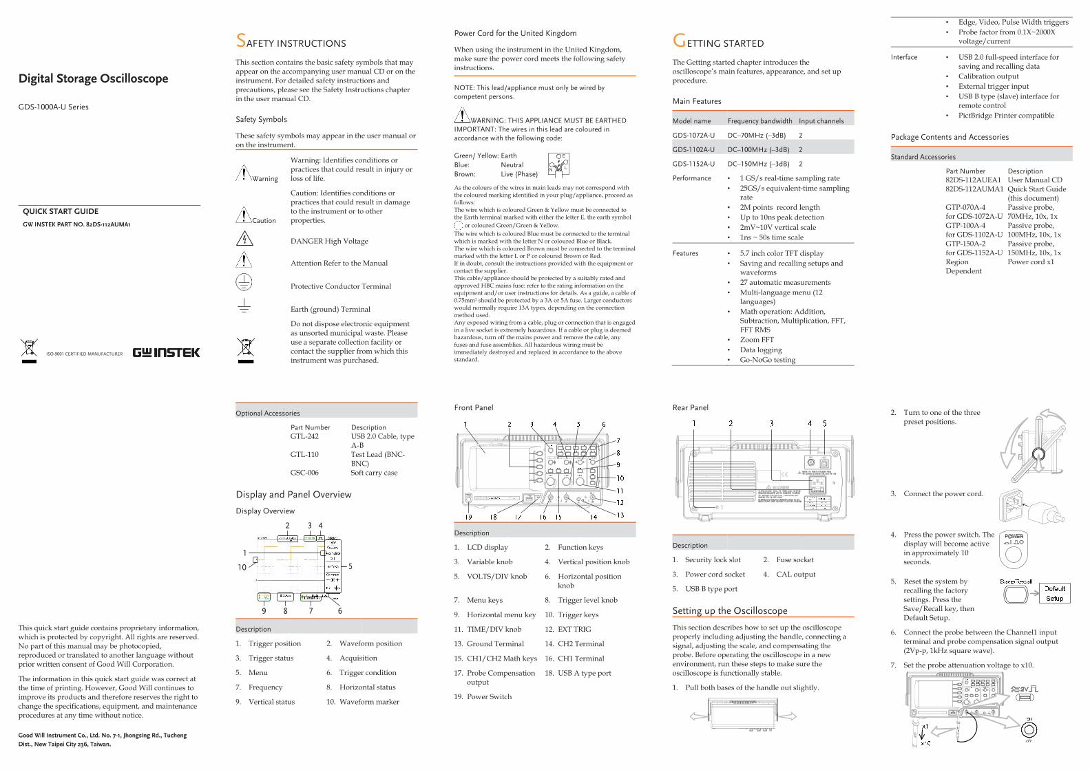
1. Pull both bases of the handle out slightly.
2. Turn to one of the three preset positions.
3. Connect the power cord.
4. Press the power switch. The display will become active in approximately 10 seconds.
5. Reset the system by recalling the factory settings. Press the Save/Recall key, then Default Setup.
6. Connect the probe between the Channel1 input terminal and probe compensation signal output (2Vp-p, 1kHz square wave).
7. Set the probe attenuation voltage to x10.
Optional Accessories
Part Number Description GTL-242 USB 2.0 Cable, type
A-B GTL-110 Test Lead (BNC-
BNC) GSC-006 Soft carry case
Display and Panel Overview
Display Overview
1
2 3 4
5
6789
10
Description
1. Trigger position 2. Waveform position
3. Trigger status 4. Acquisition
5. Menu 6. Trigger condition
7. Frequency 8. Horizontal status
9. Vertical status 10. Waveform marker
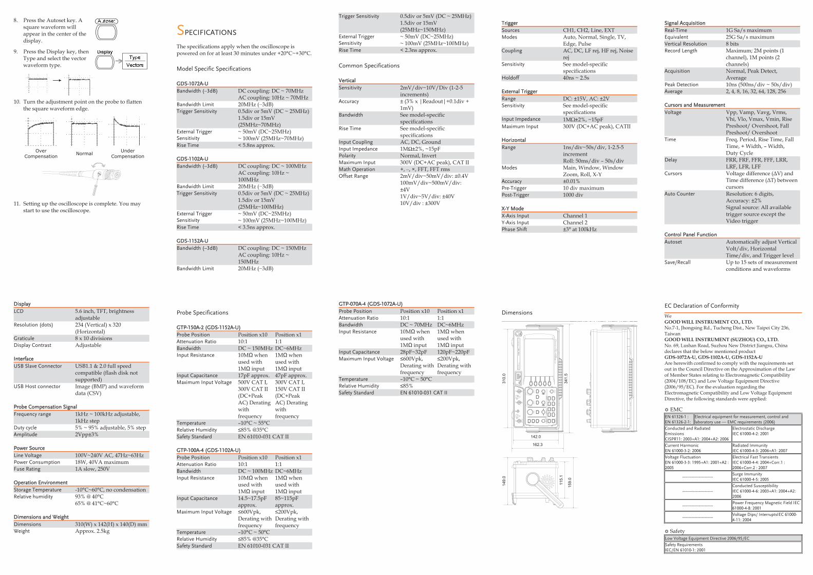
8. Press the Autoset key. A square waveform will appear in the center of the display.
9. Press the Display key, then Type and select the vector waveform type.
10. Turn the adjustment point on the probe to flatten the square waveform edge.
Over Compensation Normal Under
Compensation
11. Setting up the oscilloscope is complete. You may start to use the oscilloscope.
SPECIFICATIONS
The specifications apply when the oscilloscope is powered on for at least 30 minutes under +20°C~+30°C.
Model Specific Specifications
GDS-1072A-U Bandwidth (–3dB) DC coupling: DC ~ 70MHz
AC coupling: 10Hz ~ 70MHz Bandwidth Limit 20MHz (−3dB) Trigger Sensitivity 0.5div or 5mV (DC ~ 25MHz)
1.5div or 15mV (25MHz~70MHz)
External Trigger Sensitivity
~ 50mV (DC~25MHz) ~ 100mV (25MHz~70MHz)
Rise Time < 5.8ns approx.
GDS-1102A-U Bandwidth (–3dB) DC coupling: DC ~ 100MHz
AC coupling: 10Hz ~ 100MHz
Bandwidth Limit 20MHz (−3dB) Trigger Sensitivity 0.5div or 5mV (DC ~ 25MHz)
1.5div or 15mV (25MHz~100MHz)
External Trigger Sensitivity
~ 50mV (DC~25MHz) ~ 100mV (25MHz~100MHz)
Rise Time < 3.5ns approx.
GDS-1152A-U Bandwidth (–3dB) DC coupling: DC ~ 150MHz
AC coupling: 10Hz ~ 150MHz
Bandwidth Limit 20MHz (−3dB)
Trigger Sensitivity 0.5div or 5mV (DC ~ 25MHz) 1.5div or 15mV (25MHz~150MHz)
External Trigger Sensitivity
~ 50mV (DC~25MHz) ~ 100mV (25MHz~100MHz)
Rise Time < 2.3ns approx.
Common Specifications
Vertical Sensitivity 2mV/div~10V/Div (1-2-5
increments) Accuracy ± (3% x |Readout|+0.1div +
1mV) Bandwidth See model-specific
specifications Rise Time See model-specific
specifications Input Coupling AC, DC, Ground Input Impedance 1MΩ±2%, ~15pF Polarity Normal, Invert Maximum Input 300V (DC+AC peak), CAT II Math Operation +, –, ×, FFT, FFT rms Offset Range 2mV/div~50mV/div: ±0.4V
100mV/div~500mV/div: ±4V 1V/div~5V/div: ±40V 10V/div : ±300V
Trigger Sources CH1, CH2, Line, EXT Modes Auto, Normal, Single, TV,
Edge, Pulse Coupling AC, DC, LF rej, HF rej, Noise
rej Sensitivity See model-specific
specifications Holdoff 40ns ~ 2.5s
External Trigger Range DC: ±15V, AC: ±2V Sensitivity See model-specific
specifications Input Impedance 1MΩ±2%, ~15pF Maximum Input 300V (DC+AC peak), CATII
Horizontal Range 1ns/div~50s/div, 1-2.5-5
increment Roll: 50ms/div – 50s/div
Modes Main, Window, Window Zoom, Roll, X-Y
Accuracy ±0.01% Pre-Trigger 10 div maximum Post-Trigger 1000 div
X-Y Mode X-Axis Input Channel 1 Y-Axis Input Channel 2 Phase Shift ±3° at 100kHz
Signal Acquisition Real-Time 1G Sa/s maximum Equivalent 25G Sa/s maximum Vertical Resolution 8 bits Record Length Maximum; 2M points (1
channel), 1M points (2 channels)
Acquisition Normal, Peak Detect, Average
Peak Detection 10ns (500ns/div ~ 50s/div) Average 2, 4, 8, 16, 32, 64, 128, 256
Cursors and Measurement Voltage Vpp, Vamp, Vavg, Vrms,
Vhi, Vlo, Vmax, Vmin, Rise Preshoot/ Overshoot, Fall Preshoot/ Overshoot
Time Freq, Period, Rise Time, Fall Time, + Width, – Width, Duty Cycle
Delay FRR, FRF, FFR, FFF, LRR, LRF, LFR, LFF
Cursors Voltage difference (ΔV) and Time difference (ΔT) between cursors
Auto Counter Resolution: 6 digits, Accuracy: ±2% Signal source: All available trigger source except the Video trigger
Control Panel Function Autoset Automatically adjust Vertical
Volt/div, Horizontal Time/div, and Trigger level
Save/Recall Up to 15 sets of measurement conditions and waveforms
Display LCD 5.6 inch, TFT, brightness
adjustable Resolution (dots) 234 (Vertical) x 320
(Horizontal) Graticule 8 x 10 divisions Display Contrast Adjustable
Interface USB Slave Connector USB1.1 & 2.0 full speed
compatible (flash disk not supported)
USB Host connector Image (BMP) and waveform data (CSV)
Probe Compensation Signal Frequency range 1kHz ~ 100kHz adjustable,
1kHz step Duty cycle 5% ~ 95% adjustable, 5% step Amplitude 2Vpp±3%
Power Source Line Voltage 100V~240V AC, 47Hz~63Hz Power Consumption 18W, 40VA maximum Fuse Rating 1A slow, 250V
Operation Environment Storage Temperature -10°C~60°C, no condensation Relative humidity 93% @ 40°C
65% @ 41°C~60°C
Dimensions and Weight Dimensions 310(W) x 142(H) x 140(D) mm Weight Approx. 2.5kg
Probe Specifications
GTP-150A-2 (GDS-1152A-U) Probe Position Position x10 Position x1 Attenuation Ratio 10:1 1:1 Bandwidth DC ~ 150MHz DC~6MHz Input Resistance 10MΩ when
used with 1MΩ input
1MΩ when used with 1MΩ input
Input Capacitance 17pF approx. 47pF approx. Maximum Input Voltage 500V CAT I,
300V CAT II (DC+Peak AC) Derating with frequency
300V CAT I, 150V CAT II (DC+Peak AC) Derating with frequency
Temperature –10°C ~ 55°C Relative Humidity ≤85% @35°C Safety Standard EN 61010-031 CAT II
GTP-100A-4 (GDS-1102A-U) Probe Position Position x10 Position x1 Attenuation Ratio 10:1 1:1 Bandwidth DC ~ 100MHz DC~6MHz Input Resistance 10MΩ when
used with 1MΩ input
1MΩ when used with 1MΩ input
Input Capacitance 14.5~17.5pF approx.
85~115pF approx.
Maximum Input Voltage ≤600Vpk, Derating with frequency
≤200Vpk, Derating with frequency
Temperature –10°C ~ 50°C Relative Humidity ≤85% @35°C Safety Standard EN 61010-031 CAT II
GTP-070A-4 (GDS-1072A-U) Probe Position Position x10 Position x1 Attenuation Ratio 10:1 1:1 Bandwidth DC ~ 70MHz DC~6MHz Input Resistance 10MΩ when
used with 1MΩ input
1MΩ when used with 1MΩ input
Input Capacitance 28pF~32pF 120pF~220pF Maximum Input Voltage ≤600Vpk,
Derating with frequency
≤200Vpk, Derating with frequency
Temperature –10°C ~ 50°C Relative Humidity ≤85% Safety Standard EN 61010-031 CAT II
Dimensions
VID /
EMI
TVI
D /ST
LO
VVI
D /ST
LO
V
UN
EM
UN
EM
2 H
CH T
AM
1 H
C
Acquire
Display
Utility
Help
Run/S
top
VA
RIA
BLE
FOR
CE
Autoset
Cursor
SIN
GLE
Hardcopy
Measure
Save/R
ecall
LEV
EL
REG
GIRT
LAT
NOZ
IR
OH
LACI
TRE
V
CH
1
CAT
300VM
15pF
MAX. 300Vpk
1
CH
2EX
T TRIG
CAT
300VM
15pF
MAX. 300V
pk
1
YX
310.
0
341.
5
142.0
162.3
115.
1
149.
0
159.
0
150 MH
z 1 G S
a/s
Digital S
torage Oscilloscope
GD
S-1152A-U
EC Declaration of Conformity
We GOOD WILL INSTRUMENT CO., LTD. No.7-1, Jhongsing Rd., Tucheng Dist., New Taipei City 236, Taiwan GOOD WILL INSTRUMENT (SUZHOU) CO., LTD. No. 69, Lushan Road, Suzhou New District Jiangsu, China declares that the below mentioned product GDS-1072A-U, GDS-1102A-U, GDS-1152A-U Are herewith confirmed to comply with the requirements set out in the Council Directive on the Approximation of the Law of Member States relating to Electromagnetic Compatibility (2004/108/EC) and Low Voltage Equipment Directive (2006/95/EC). For the evaluation regarding the Electromagnetic Compatibility and Low Voltage Equipment Directive, the following standards were applied:
EMC EN 61326-1 : EN 61326-2-1:
Electrical equipment for measurement, control and laboratory use –– EMC requirements (2006)
Conducted and Radiated Emissions CISPR11: 2003+A1: 2004+A2: 2006
Electrostatic Discharge IEC 61000-4-2: 2001
Current Harmonic EN 61000-3-2: 2006
Radiated Immunity IEC 61000-4-3: 2006+A1: 2007
Voltage Fluctuation EN 61000-3-3: 1995+A1: 2001+A2 : 2005
Electrical Fast Transients IEC 61000-4-4: 2004+Corr.1 : 2006+Corr.2 : 2007
------------------------- Surge Immunity IEC 61000-4-5: 2005
------------------------- Conducted Susceptibility IEC 61000-4-6: 2003+A1: 2004+A2: 2006
------------------------- Power Frequency Magnetic Field IEC 61000-4-8: 2001
------------------------- Voltage Dips/ InterruptsIEC 61000-4-11: 2004
Safety Low Voltage Equipment Directive 2006/95/EC
Safety Requirements IEC/EN 61010-1: 2001