Embed Size (px)
Citation preview
Section 1 Scope ......................................114-11.3
Section 2 Referenced Documents...........114-11.3
Section 3 Terminology & Units..............114-11.4
Section 4 Significance of Use.................114-11.5
Section 5 General Information ...............114-11.5
Section 6 Applicable Documents andGlossary..............................114-11.6
Section 7 General Requirements ............114-.11.8
Section 8 Performance Requirements andTests ....................................114-11.8
Section 9 Manufacturing and Field InstallationRequirements ......................114-11.14
Appendix A Test Procedure for AboveDeck CombustibilityASTM E 108.......................114-11.17
Appendix B Test Procedure for SimulatedDynamic Uplift PressureResistance of MechanicallyAttached Roof SystemAssemblies..........................114-95.19
Appendix C Test Procedure for SimulatedUplift Pressure Resistance ofRoof System Assemblies ....114-95.23
Appendix D Test Procedure for Simulated UpliftPressure Resistance of AdheredRoof System Assemblies ....114-11.27
Appendix E Test Procedure for CorrosionResistance of Fasteners,Batten Bars and StressDistribution Plates ..............114-95.31
Appendix F Test Procedure for Susceptibilityto Hail Damage for Roof SystemAssemblies..........................114-95.35
Appendix G Test Procedure for Susceptibility toLeakage for Roof SystemAssemblies..........................114-95.37
Appendix H Test Procedures for SmallScale QC and PhysicalProperties of Approved Roof SystemAssemblies..........................114-95.39
Appendix I Test Procedure for Staticand Dynamic PunctureResistance of Approved Roof SystemAssemblies..........................114-95.41
Appendix J Test Procedure for 12' x 24'Simulated Uplift PressureResistance of Roof SystemAssemblies..........................114-95.49
Appendix K Test Procedure for F.I.T.Classification of ModifiedBitumen Roof SystemAssemblies..........................114-95.53
2010 FLORIDA BUILDING CODE — TEST PROTOCOLS HVHZ (TAS) 114-11.1
TESTING APPLICATION STANDARD (TAS) No. 114-11
TEST PROCEDURES FOR ROOF SYSTEM ASSEMBLIESIN THE HIGH-VELOCITY HURRICANE ZONE JURISDICTION
TABLE OF CONTENTS

(TAS) 114-11.2 2010 FLORIDA BUILDING CODE — TEST PROTOCOLS HVHZ
Scope:1.
1.1 This protocol covers the requirements forapproval of membrane roof systemassemblies in the high-velocity hurricanezone jurisdiction. An approved mem-brane roof cover is one that meets the cri-teria of this protocol for acceleratedweathering, corrosion of metal parts,F.I.T. [Fatigue, Indentation (dynamic andstatic puncture) & Temperature], fire, foottraffic, hail, leakage, and wind.
1.2 This protocol applies to any membraneroof cover intended to protect the roof as-sembly and building contents from theweather.
1.3 The performance of a membrane roofcover depends partially on the substratematerials over which it is applied. It istherefore necessary to evaluate the roofsystem assembly as a whole, including thecover and auxiliary items necessary tobuild up a roof system assembly. Thesecomponents are included within the sub-ject test criteria.
1.4 This Protocol is intended to evaluate onlythose hazards investigated, and is not in-tended to determine suitability for the enduse of product.
1.5 This protocol evaluates roof systemassemblies for their performance regard-ing accelerated weathering characteris-tics, corrosion resistance of metal parts,[(Fatigue, Indentation (dynamic andstatic puncture) & Temperature)], exter-nal fire (fire or burning debris fromabove), foot traffic resistance, susceptibil-ity from hail storm damage, leakage, andsimulated wind uplift.
1.6 Approval is based on satisfactory evalua-tion of the product(s) and manufacturer inthe following major areas:
1.6.1 Examination and tests to evaluate:1) the performance of the product
as required by the authority hav-ing jurisdiction, and, as far aspractical, 2) the marking proce-dures which shall be used to iden-tify the product as set forth inSection 1517 of the Florida Build-ing Code, Building.
1.7 Continued approval is based upon:
1.7.1 production or availability of theproduct as currently approved;
1.7.2 the continued use of acceptablequality control procedures;
1.7.3 satisfactory field experience; and,
1.7.4 compliance with the terms andconditions of the Product Ap-proval.
1.8 All testing and calculations shall be con-ducted by an approved testing agency andall test reports, including calculations,shall be signed and sealed by a profes-sional engineer.
1.9 Design pressures calculated in accor-dance with ASCE 7 are permitted to bemultiplied by 0.6 for the purposes of com-paring to tested pressures in TAS 114.
Referenced Documents:2.
2.1 Florida Building Code, Building:Chapters 15 and 16 (High-Velocity Hurri-cane Zones)
2.2 Application Standards:
TAS 105 Field Withdrawal Resis-tance Test Procedure
TAS 105 Field Withdrawal Resis-tance
Appendix A Test Results Report
2.3 Application Standards:
2010 FLORIDA BUILDING CODE — TEST PROTOCOLS HVHZ (TAS) 114-11.3
TESTING APPLICATION STANDARD (TAS) No. 114-11
TEST PROCEDURES FOR ROOF SYSTEM ASSEMBLIESIN THE HIGH-VELOCITY HURRICANE ZONE JURISDICTION
RAS 111 Standard Requirements forAttachment of PerimeterFlashing and Woodblock-ing
RAS 117 Standard Requirements forBonding or Mechanical At-tachment of Insulation Pan-els and MechanicalAttachment of Anchor orBase Sheets to VariousSubstrates
RAS 137 Standard Requirements forMechanical Attachment ofSingle-Ply Membrane RoofCoverings to Various Sub-strates
2.4 Factory Mutual Engineering Corpora-tion:Loss Prevention Data Sheet 1-7, April,1983Loss Prevention Data Sheet 1-28, Sep-tember, 1991Loss Prevention Data Sheet 1-28(S), No-vember, 1991Loss Prevention Data Sheet 1-30, May,1990Loss Prevention Data Sheet 1-48, June,1991
2.5 Factory Mutual Research CorporationApproval Standards:
4450 Class I Insulated Steel DeckRoofs
4470 Class I Roof Covers Annual Ap-proval Guide, 1994
2.6 The American Society of Civil Engineers(ASCE):ASCE 7; Minimum Design Loads forBuildings and Other Structures
2.7 ASTM Standards:
A 90 Standard Test Method forWeight of Coating onZinc-Coated (Galvanized) Ironor Steel Articles
A 641 Standard Specification forZinc-Coated (Galvanized) Car-bon Steel Wire
B 117 Standard Test Method for SaltSpray (Fog) Testing
D 638 Standard Test Method for Ten-sile Properties of Plastics
D 751 Standard Test Methods forCoated Fabrics
D 1781 Standard Test Method forClimbing Drum Peel for Adhe-sives
E 70 Standard Test Method for pH ofAqueous Solutions With theGlass Electrode
E 108 Standard Test Methods for FireTests of Roof Coverings
E 380 Excerpts from the StandardPractice for Use of the Interna-tional System of Units (SI) (theModernized Metric System)
G 23 Standard Practice for OperatingLight-Exposure Apparatus(Carbon-Arc Type) With andWithout Water for Exposure ofNonmetallic Materials
G 26 Standard Practice for OperatingLight-Exposure Apparatus (Xe-non-Arc Type) With and With-out Water for Exposure ofNonmetallic Materials
G 53 Standard Practice for OperatingLight- and Water-Exposure Ap-paratus (Fluorescent UV-Con-densation Type) for Exposure ofNonmetallic Materials
G 85 Standard Practice for ModifiedSalt Spray (Fog) Testing
2.8 DIN Standards:
50018 Testing in a Saturated Atmo-sphere in the Presence of SulfurDioxide
2.9 Norwegian Building Research Institute:Roof Coverings: Dynamic Wind-LoadResistance
2.10 Roof Consultants Institute:Glossary of Terms
2.11 Centre Scientifique et Technique duBatimentClassification for Roofing Systems
Terminology & Units:3.
3.1 Definitions—For definitions of termsused in this Protocol, refer to Chapter 2and Section 1513 of the Florida BuildingCode, Building; and/or Section 6.2,
(TAS) 114-11.4 2010 FLORIDA BUILDING CODE — TEST PROTOCOLS HVHZ
(TAS) No. 114-11
herein; and/or the RCI Glossary of Terms.The definitions of the Florida BuildingCode, Building shall take precedence.
3.2 Units—For conversion of U.S. customaryunits to SI units, refer to ASTM E 380.
Significance of Use:4.
4.1 The requirements of this protocol arebased on experience, research and testingor the standards of other national and in-ternational organizations. The advice ofmanufacturers, users, and trade associa-tions is also considered.
4.2 Meeting these requirements will qualify aproduct as a Product Approved roofsystem assembly. An approved roofsystem assembly of itself is not a signifi-cant fire hazard when reviewed from theaspect of external fire, and can withstandexpected wind uplift forces, hail stones,etc., when installed in accordance with allProduct Approval requirements. Ap-proval requirements prohibit substitutionof components in the roof system assem-bly without a revision to the manufac-turer’s Product Approval. Please note thatsome Approvals include modified use ofterminology relating to performance inhail. The High-Velocity Hurricane Zonejurisdiction is considered a moderate hailzone, as noted on the National HailstormMap published by the National Oceanicand Atmospheric Administrat ion(NOAA).
4.3 Products that do not conform to these re-quirements may be Approved if they meetthe intent of this Protocol. Conversely,those that do conform may not be Ap-proved if other conditions prevail.
4.4 Effective date of revision:
4.4.1 The effective date of a protocolmandates that all products testedfor Approval after the effectivedate must satisfy the requirementsof that protocol. Products Ap-proved under a previous Protocolmust comply with the new versionby the effective date or such dateestablished by the Authority Hav-ing Jurisdiction or else forfeitProduct Approval. The effective
date may apply to the entire proto-col, or, where so indicated, only tospecific paragraphs of the proto-col.
4.4.2 The effective date of this protocolis January 31, 1995, for full com-pliance with performance require-ments.
General Information:5.
5.1 Roof covers:
5.1.1 Roof covers are supplied in eitherroll, sheet or liquid form. Theymay be fabricated in multi-plies(layers) or as a single ply. The sin-gle ply sheets are usually manufac-tured from thermoplastic materials(e.g., PVC - polyvinyl chloride);thermostat materials (e.g) EPDM -ethylene propylene diene mono-mers); uncured elastomer materi-als (e.g., PIB - polyisobutylene); ormodified bitumen materials (e.g.rubberized asphalt or asphalt satu-rated or coated materials). The liq-uid covers may be supplied assil icone, polyurethane,chlorosulfonated polyethylene,acrylic, etc. Multiply systems maybe various bituminous or coal tarpitch systems utilizing organic, fi-berglass or polyester reinforcedbase, anchor or interply reinforce-ment.
5.2 Application of this standard:
5.2.1 To qualify as an approved roofsystem assembly, each assemblyshall satisfy all of the followingperformance criteria, and be in-stalled as tested over specific insu-lations and/or decks. Insulatedand uninsulated deck types arelisted in Product Approvals as fol-lows:
• Wood;
• Steel;
• Concrete;
• Lightweight concrete;
2010 FLORIDA BUILDING CODE — TEST PROTOCOLS HVHZ (TAS) 114-11.5
(TAS) No. 114-11
• Cementitious wood fiber;and,
• Poured gypsum concrete.
5.2.2 The Approval examination in-cludes 1) accelerated weathering;2) corrosion resistance of metalparts; 3) F.I.T. testing which in-cludes fatigue, dynamic and staticpuncture and temperature testing(F.I.T. testing is specified formodified bitumen roof mem-branes only; however, static anddynamic puncture testing is re-quired for all membrane types); 4)external fire; 5) foot traffic, 6)simulated hail resistance; 7) waterleakage resistance; 8) simulatedwind uplift, and other tests asnoted. A complete review of con-struction and application specifi-cations and details shall beconducted to insure, as far as pos-sible, a practical and reliable in-stallation.
5.2.3 As noted in Section 4.2, approvedcomponents within a roof systemassembly may not be substitutedwith components not listed inProduct Approvals. However ex-isting data in Product Approvalsmay be extrapolated, in compli-ance with methods set forth inRAS 117 (for insulation or basesheet attachment) or RAS 137 (forsingle-ply membrane attach-ment), to determine acceptablefastener spacings in elevated pres-sure zones.
Applicable Documents and Glossary:6.
6.1 Applicable documents:
6.1.1 The following standards, testmethods and practices are refer-enced in this protocol and aresummarized in the appendicesherein.
• Fire tests of roof coverings -ASTM E 108, American So-ciety for Testing and Materi-als
• Roof coverings: dynamicwind-load resistance, Norwe-
gian Building ResearchInstitute
• Uplift pressure test standardfor Class I roof covers, Fac-tory Mutual Research Corpo-ration
• Uplift pull test standard forAdhered Class I Roof Covers,Factory Mutual ResearchCorporation
• Modified Salt Spay (Fog)Testing–ASTM G 85, Ameri-can Society for Testing andMaterials
• Testing in a Saturated Atmo-sphere with the Presence ofSulfur Dioxide–DIN 50018
• Susceptibility to Hail DamageTest Standard for AdheredClass I Roof Covers, FactoryMutual Research Corporation
• Susceptibility to Leakage Testfor Class I Roof Covers, Fac-tory Mutual Research Corpo-ration
• Small Scale QC and PhysicalProperties Tests for Class IRoof Covers, Factory MutualResearch Corporation
• 12 foot by 24 foot Uplift TestProcedure, Factory MutualResearch Corporation
• F.I.T. Classification for Roof-ing Systems–CentreScientifique et Technique duBatiment
6.2 Glossary–The following definitions shallrelate to this protocol only.
Adhere: To cause two surfaces to be heldtogether by adhesion. Single-ply mem-branes are often “partially-” or “to-tally-adhered” to a substrate with the useof contact cements, such as air-cured phe-nolic-neoprene mixtures, or other similaradhesives.
Ballast: An anchoring material, such asrounded river rock, gravel, or precast con-crete pavers, which is used to hold sin-gle-ply roofing membranes in place andto stabilize the roof system from wind up-lift forces. Although ballasting materials
(TAS) 114-11.6 2010 FLORIDA BUILDING CODE — TEST PROTOCOLS HVHZ
(TAS) No. 114-11
differ greatly in size, composition, andweight, they are typically applied at aminimum rate between 10 and 15 poundsper square foot of roof area. Thus, ballastshould be applied only to those roof struc-tures able to support this added weight.Also, ballast materials should be large andheavy enough to resist being blown off theroof, yet light and smooth enough to avoiddamaging the membrane. (Systems utiliz-ing these applications are not generallyapproved in the high-velocity hurricanezone jurisdiction.)
Batten: A narrow metal band or plate,usually of galvanized steel or aluminum,which is used to fasten or hold in place asingle-ply membrane, to prevent its dis-placement.
Delamination: Separation of the plies in aroof membrane or system in any lami-nated roofing material or component, e.g.,laminated layers of rigid insulation or thefelt plies in a built-up roof.
Disc Fasteners: A wide variety of devicesof mechanical assemblies used to attachsingle-ply membranes, insulation boardsand/or base sheets to a substrate or deck.Disc attachments generally consist of asquare- or circular-shaped plate with ahole in the center, through which a screwor nail-like clip may be inserted. They aregenerally set in place with a drill-like de-vice.
EPDM: Designated nomenclature for atripolymer of ethylene, propylene, anddiene.
Field Seam: A splice made in the fieldwhich joins two sheets together using anadhesive splicing tape, or heat- or sol-vent-welding.
Heat Welding: A process or method ofmelting and sealing or fusing the overlap-ping edges of separate sections of thermo-plastic or uncured elastomeric roofingmembranes by the application of heat andpressure. Small, portable “hot air” or“heat welding” devices are availablewhich can, without the use of chemicalsor adhesives, heat seal or fuse togetheroverlapping edges to form waterproofseams.
Loosely Laid: Membranes which are notattached to the substrate except at the per-imeter of the roof and at projections.Loosely laid membranes are held in placewith appropriate and adequate ballast,
such as round river washed stone, gravel,pavers, etc. This assembly may be usedonly on roof structures able to support theadded weight of the ballast, which is gen-erally applied at a minimum rate of 10pounds per square foot of roof area.(These systems are not generally ap-proved in the high-velocity hurricanezone jurisdiction.)
Mechanically Fastened Membrane:Generally used to describe single-plymembranes which have been positivelyattached at intervals to the substrate, usu-ally with various fasteners and other me-chanical devices such as battens.Mechanical fastening permits the mem-brane to float free between the fasteners,and allows greater movement between themembrane and the substrate than in fullyadhered systems.
Modified Bitumen: A material consistingof bitumen which has been modifiedthrough the inclusion of one or more poly-mers and may contain stabilizers andother additives. Modified bitumen roof-ing membranes may also contain a rein-forcing material.
Partially Adhered: A roofing assembly inwhich the membrane has been “spot af-fixed” to a substrate, usually with an adhe-sive, such as contact cement, or amechanical device.
Polyisobutylene (PIB): A synthetic un-cured elastomer produced by thecopolymerization of isobutylene andisoprene. PIB roofing membranes arecomposed of polyisobutylene, and vari-ous other reinforcing fillers and stabiliz-ers.
Polyvinylchloride (PVC): A thermoplas-tic polymer, synthesized from vinyl chlo-ride monomer. Membranes containingpolyvinyl chloride are used in single-plyroofing membranes.
Self-Adhesive Membranes: Single-plymembranes which can adhere to a sub-strate and to itself at overlaps without theuse of an adhesive. The undersurface of aself-adhesive membrane is protected by a“release paper” that prevents the mem-brane from bonding to itself during ship-ping and handling. Later, as themembrane is unrolled, the release paper ispeeled away, and the self-adhering under-surface is applied to the substrate. Suc-cessful application of a self-adhesive
2010 FLORIDA BUILDING CODE — TEST PROTOCOLS HVHZ (TAS) 114-11.7
(TAS) No. 114-11
membrane requires a clean and dry sub-strate and the application of firm, uniformpressure.
Single-Ply Membranes: Roofing mem-branes that are field applied using just onelayer of membrane material (either ho-mogenous or composite) rather than mul-tiple layers. However, the manufacture ofthe single-ply sheeting may involve lami-nation or several layers of the same or dif-ferent materials.
Thermoplastic: Polymers that softenwhen heated and harden when cooled.This process is repetitive provided thematerial is not heated above the point atwhich decomposition occurs.
Thermoset: A material that solidifies or“sets” irreversibly when heated. Thisproperty is usually associated withcrosslinking of the molecules induced byheat or radiation.
TPO: Designated nomenclature for ther-moplastic olefin elastomer based sin-gle-ply sheets made from blends ofpolypropylene and ethyl-ene-polypylenene rubber.
Wind Uplift: The force generated by windon a roof system or components in a roofsystem resulting from wind-induced pres-sures. Wind that is deflected around andacross the surfaces of a building causes adrop in air pressure immediately abovethe roof surface. As a result, the air in thebuilding will flow beneath the membraneand roof deck and tend to lift the roof up-ward. Wind uplift may also be caused bythe introduction of wind underneath themembrane and roof edges, where it cancause the membrane to balloon and pullaway from the substrate. Roof loss bywind can be avoided or prevented byproper installation and adequate adhe-sion, attachment, or ballasting.
General Requirements:7.
7.1 During the initial investigation and beforephysical testing, the manufacturer’s spec-ifications and details shall be reviewed toassess the ease and practicality of installa-tion and use. Confirmation of specifica-tions and details are assessed through aninspection of a field application orthrough viewing of a video of an applica-tion which includes all pertinent areas ofthe application. The product shall be ca-
pable of being used within the limits of theApproval investigation.
7.2 Markings:
7.2.1 Packaging material and/or con-tainers shall bear the manufac-turer’s name and productidentification in compliance withprovisions set forth Section 1517of the Florida Building Code,Building.
7.2.2 Product shall be marked by em-bossing, painting or cutting incompliance with Florida BuildingCode, Building requirements.
7.3 Instructions:
7.3.1 Printed, published installation in-structions shall be provided by themanufacturer to demonstrateproper installation procedures tobe followed by installers. As partof the approval examination, atleast one inspection of a field in-stallation, during and/or after itscompletion, shall be required. Insome cases, a continued programof inspections shall be necessaryto assess the application proce-dures or changes within the appli-cation techniques.
7.3.2 Review of a Factory Mutual Ap-proval Report and/or the listing ofthe roof system assembly in thecurrent edition of the Factory Mu-tual Approval Guide may be, atthe discretion of the chief compli-ance officer, sufficient evidence ofcompliance with any portion ofthis protocol.
Performance Requirements and Tests:8.
8.1 General
8.1.1 This protocol is intended to evalu-ate a roof system assembly for itsperformance as it relates to accel-
(TAS) 114-11.8 2010 FLORIDA BUILDING CODE — TEST PROTOCOLS HVHZ
(TAS) No. 114-11
erated weathering, corrosion ofmetal parts, F.I.T. performance(Fatigue, Indentation and Tem-perature), fire, foot traffic, hail,leakage, and wind. The applicantmay submit up to five roof systemassemblies in its Application forProduct Approval. The AuthorityHaving Jurisdiction shall respond,in writing, stating which testsshall be required for sufficient evi-dence of compliance.
8.2 Combustibility:
Note: Roof adhesives effect the potential firespread properties of a roof system as-sembly. In addition, combustible adhe-sives are susceptible to ignition duringroof construction and cure periods.Therefore, fire testing shall be done af-ter a minimum 28 day cure period.
8.2.1 External fire testing shall be instrict compliance with ASTM E108, as noted in Appendix Aherein.
8.2.2 Testing shall include:
• spread of flame;
• intermittent flame;
• burning brand; and
• flying brand
tests as applicable.
8.2.3 Tests of alternate constructionsmay be waived by the AuthorityHaving Jurisdiction if consideredless hazardous than those previ-ously tested.
8.2.4 During these tests, there shall beno flaming or burning particlesblown off the test assembly andreaching the floor.
8.3 Wind resistance:
Note: Perimeter flashing, including metalcomponents, shall be in fabricated andinstalled in compliance with RAS 111for all approved roof system assem-blies.
8.3.1 Totally or partially adhered roofsystem assembly:
8.3.1.1 Requirements:
• The adhesive(s) usedto bond insulationand/or roofing plys ormembrane shall pene-trate or adhere to thesubstrates sufficientlyto establish an ade-quate bond withoutdegradation of the in-sulation. It shall besufficiently fluid foreffective applicationin accordance with themanufacturer’s direc-tions. In addition, theapplication shall notbe adversely affectedby temperature ex-tremes. Applicationswithin the FloridaBuilding Code, Build-ing jurisdiction gener-ally take place attemperatures above70°F (21°C).
• The adhesives shallachieve substantialadhesion with the in-sulation and at the lapswithin a minimumspecified time suchthat winds will not liftthe covering and/orinsulation before theadhesive bond hasfully developed. Thesolids within the adhe-sive shall generally re-main in suspension.Any settlement mustbe redispersed after 5minutes of agitation.Adhesives shall be de-signed and formulatedto facilitate reliablefield application ac-cording to themanufacturer’s speci-fications. All adhe-sives shall be labeled
2010 FLORIDA BUILDING CODE — TEST PROTOCOLS HVHZ (TAS) 114-11.9
(TAS) No. 114-11

with maximum“open” time in a hightemperature, high hu-midity climate to re-duce the chance ofapplication spoiledadhesive.
8.3.1.2 Simulated uplift testing
• After a 4 day labora-tory cure time at ambi-ent conditions, thetotally or partially ad-hered roof system as-sembly shal l beinitially tested for up-lift resistance in com-pliance with the testprocedures outlined inAppendix C, D, H orJ, herein. The roofsystem assembly shallattain a passing loadnot less than 30 psf(1.5 kPa). Thereafter,the roof system as-sembly test specimenshall be allowed tocure for the remainingcure time. Failure tomeet this initial four(4) day cure time up-lift criteria shall resultin failure of the roofsystem assembly andno further testing shallbe conducted.
• After the remaininglaboratory cure time,the totally or partiallyadhered roof systemassembly shall betested for uplift resis-tance in compliancewith the test proce-dures outlined in Ap-pendix C, D or J,herein.
8.3.2 Mechanically attached roof sys-tem assembly:
8.3.2.1 Mechanically attachedroof covers are held inplace by “single-type” or“batten type” fastener as-semblies.
• “Single-type” fas-tener assemblies in-clude a fasteneraccompanied by astress distributionplate which is in-stalled in a specificpattern to secure roof-ing componentswithin a roof systemassembly. Stressplates are available ina variety of shapes andsizes, each of whichmay provide differinguplift resistance re-sults when installedwith the same fastenerin an identical pattern.They may be: 1) in-stalled under the roofcover with adhesiveapplied to the top sur-face of the plate; 2) in-stalled through theroof cover and sealed;3) installed within thelap as the covering isbeing installed; or, 4)installed under theroof cover with an in-tegral fastener above(non-piercing types).
• “Batten-type” fas-tener assemblies havea long bar or battenstrip through whichthe fasteners aredriven. They are usu-al ly instal led: 1)through the roof coverwith a patch or sealantapplied over the bat-ten; 2) as the cover isbeing installed withinthe lap; or, 3) underthe roof cover with anintegral fastener ap-plied over the cover(non-piercing type).
8.3.2.2 Requirements:
• Fasteners and stressplates shall be testedin compliance withthe requirements set
(TAS) 114-11.10 2010 FLORIDA BUILDING CODE — TEST PROTOCOLS HVHZ
(TAS) No. 114-11

forth in TAS 117, Ap-pendices A, B and C.
• All fasteners, otherthan base ply fasten-ers, shall record awithdrawal resistancevalue under static loadgreater than or equalto 275 lbf (1220 N)and a withdrawal re-sistance value underpulsating load greaterthan or equal to 175lbf (778 N) whentested in compliancewith Appendix A ofTAS 117.
• Fasteners shall be ofproper length to pene-trate the roof deck, ifapplicable. For steeldeck application, fas-teners must penetratethe top flange. Fasten-ers shall hold securelyin the structural deckand prevent the cover-ing from being liftedoff. The fastening sys-tem shall secure theinsulation in place un-der the roof cover.(Preliminary fastenersshall be used to main-tain the insulation inplace under the cover.See RAS 117.) If fas-teners are installedwithin the lap, theyshall be installed so asnot to weaken the fieldseam. Any separationor delamination at thefield seam that wouldrequire remedial mea-sures shall be con-sidered a fai lure .Materials and designshall be adequate toprevent fastener fail-ure. The design mustinsure permanent se-curement to the deck,resisting horizontaland vert ical deckmovement due to tem-perature changes, live
loads on the roof, andto vibration.
• The fastener shall becapable of proper in-stallation with the rec-o m m e n d e dequipment withoutdamage to the roofcover. The fastenerapplication density orspacing shall be ini-tially verified throughsimulated uplift pres-sure testing, as notedin Section 8.3.2.3,herein. Data extrapo-lation for fastenerdensity or spacingshall be conducted instrict compliance withRAS 117 (for insula-tion or base sheet at-tachment) or RAS 137(for single-ply mem-brane attachment).Data extrapolation islimited by the testmethod utilized forsimulated uplift test-ing. (See Sect ion8.3.2.3, herein.)
• A minimum of twoapproved insulationfastener assembliesare required for pre-liminary attachmentof insulation panelshaving dimensionsless than or equal to 4feet by 4 feet (1.2 m by1.2 m). A minimum offour approved insula-tion fastener assem-blies are required forpreliminary attach-ment of insulationpanels having dimen-sions greater than to 4feet by 4 feet (1.2 m by1.2 m).
8.3.2.3 Simulated uplift testing:
• Mechanical ly at-tached Roof SystemAssemblies shall betested using one ormore of the tes t
2010 FLORIDA BUILDING CODE — TEST PROTOCOLS HVHZ (TAS) 114-11.11
(TAS) No. 114-11
procedures outlined inAppendices B, C,and/or J.
• The test procedureoutlined in AppendixB is a dynamic uplifttest utilizing a dy-namic wind chamberfor testing of all me-chanically attachedroof system assem-blies having a maxi-mum fastener rowspacing of 72 inches.Appendix B simu-lated uplift testinggenerates a fastenerassembly design valueand a maximum al-lowable fastener den-sity or spacing. Thismaximum allowablefastener density orspacing may be al-tered through data ex-trapolation, in com-pliance with RAS 137(for single-ply mem-brane attachment), tomeet design pressuresfor a specific building.
• The test procedureoutlined in AppendixC is a static uplift testutilizing a 5 foot by 9foot (1.5 m by 2.7 m)pressure vessel fortesting of mechanic-ally attached roof sys-tems assemblies witha row spacing lessthan or equal to 48inches (1.2 m) o.c. or afastener grid spacingless than or equal to 12inches by 24 inches(0.6 m by 1.2 m); (8square feet per attach-ment point). The roofsystem assembly shallattain a passing loadnot less than 90 psf(4.2 kPa) . Datagenerated from Ap-pendix C simulated
uplift testing may notbe used for extrapola-tion.
• The test procedureoutlined in AppendixJ is a static uplift testutilizing a 12 feet by24 feet (3.6 m by 7.6m) pressure vessel fortesting of mechani-cally attached roofsystems assemblieswith a row spacinggreater than 48 inches(1.2 m) o.c. or a fas-tener grid spacinggreater than 12 inchesby 24 inches (0.6 m by1.2 m); (8 square feetper attachment point).The roof system as-sembly shall attain apassing load not lessthan 90 psf (4.2 kPa).Data generated fromAppendix J simulateduplift testing may beused for extrapola-tion, in compliancewith RAS 137 (forsingle-ply membraneattachment), to meetdesign pressures for aspecific building. Ex-trapolation of datafrom Appendix J sim-ulated uplift testing islimited to 1.75 timesthe maximum upliftpressure noted in theProduct Approval.
• The Authority HavingJurisdiction may, athis/her option, acceptand publish in ProductApprovals roof sys-tem assemblies that donot meet the minimum90 psf (4.2 kPa) upliftcriteria providing themanufacturer has oneor more assembliesthat meet the mini-mum uplift criteria.
(TAS) 114-11.12 2010 FLORIDA BUILDING CODE — TEST PROTOCOLS HVHZ
(TAS) No. 114-11
8.4 Corrosion Resistance:
8.4.1 Nails and carbon steel fasteners:
8.4.1.1 All nails and carbon steelfasteners shall be testedfor corrosion resistance incompliance with ASTMStandard Practice G 85[(Modified Salt Spray(Fog) Testing)], AnnexA5 (Dolute ElectrolyteCyclic Fog/Dry Testing)as modified for the high-velocity hurricane zoneand noted in Section 2 ofAppendix E, herein.
8.4.2 Batten bars, stress distributionplates and fasteners (other thannails):
8.4.2.1 All batten bars, stress dis-tribution plates, and metalfasteners (other than nails)shall be tested for corro-sion resistance in compli-ance with DIN 50018 asnoted in Section 3 of Ap-pendix E, herein.
8.4.2.2 Each specimen shall beexposed to air saturatedwith water vapor (104°F,40°C) containing a mildconcentration of sulfur di-oxide for 8 hours, fol-lowed by a drying periodof 16 hours at room tem-perature. After each dry-ing cycle, the specimenshall be inspected andsigns of corrosion or rustshall be recorded.
8.4.2.3 The 24-hour cycle shall berepeated 15 times and thecorrosion percentage shallbe recorded.
8.4.2.4 To evaluate the corrosionincrease after Cycle 1through Cycle 15, thespecimen shal l bemounted to blue paintedsheet backdrop.
8.5 Hail resistance:
Note: The high-velocity hurricane zone jurisdic-tion is a “moderate hail” area, as desig-nated by the National Oceanic andAtmospheric Administration (NOAA).
8.5.1 The roof system assembly shall betested for hail damage resistancein compliance with either of theSimulated Hail Damage Test pro-cedures noted in Appendix F,herein. A minimum of ten dropsfrom the impactor is required, fiveof which shall be conducted in afield-fabricated seam or flashingdetail where appropriate.
8.5.2 The roof cover and the field seamshall not show signs of cracking,splitting, internal separation,delamination, or rupture. Underadhered conditions, minor separa-tion of the roof cover from thesubstrate (directly under the im-pact area) is acceptable perfor-mance for monolithic decks only(e.g. lightweight concrete, struc-tural concrete, and gypsum, etc.).Severe degradation, such ascracking, crushing, etc., of thedeck itself is reason for failure.The cover thickness shall bechecked at the points of impact.
8.6 Water leakage:
8.6.1 The roof cover shall be tested forwater leakage resistance in com-pliance with the Water LeakageTest procedures noted in Appen-dix G, herein. A sample 18 inches(45 cm) in diameter shall be pre-pared and, where appropriate, afield seam and/or penetration de-tail shall be included. The sampleshall be conditioned (weathered)for 1000 hours in a fluorescent ul-traviolet condensation typeweathering apparatus before be-ing cut into a size 10 inches (25cm) in diameter and placed in theleakage test apparatus. The sam-ple shall be maintained at ambientconditions.
2010 FLORIDA BUILDING CODE — TEST PROTOCOLS HVHZ (TAS) 114-11.13
(TAS) No. 114-11
8.6.2 The roof cover and field seamand/or penetration detail shall notshow signs of a leakage during orat the end of the 7 day period.
8.7 Accelerated weathering:
8.7.1 Accelerated weathering testingshall be in strict compliance withASTM G 23 or G 26.
8.8 F.I.T. Testing (F = Fatigue, I = Indenta-tion, T = Temperature):
Note: Complete F.I.T. testing is required formodified bitumen roof membranes only;however, static and dynamic puncture re-sistance testing, which forms a part ofF.I.T., is required for all membrane types.
8.8.1 Fatigue:
8.8.1.1 Fatigue testing of modi-fied bitumen roofingmembranes shall be incompliance with the testprocedures outlined inAppendix K, herein.
8.8.2 Static and dynamic puncture:
8.8.2.1 Static and dynamic punc-ture resistance testingshall be in strict compli-ance with the test proce-dures outl ined inAppendix I, herein.
8.8.3 Temperature:
8.8.3.1 Temperature testing ofmodified bitumen roofingmembranes shall be incompliance with the testprocedures outlined inAppendix K, herein.
8.9 Resistance to foot traffic:
8.9.1 Resistance to foot traffic testingshall be in strict compliance withthe test procedures outlined in thissection.
8.9.2 Test:
8.9.2.1 A 3 inch (76 mm) squaresteel plate with rounded
corners shall be centeredon the centerline of a 12inch (305 mm) square hor-izontal panel and posi-tioned along the butt edgeand side joint of the insu-lation boards.
8.9.2.2 A 200 lbf (889 N) loadshall be imposed on theplate. The superimposedload shall be reduced tozero and the sample coverreloaded a minimum offour additional times, withpenetration and residualreadings taken each timewithout removing theplate. The specimen shallbe inspected after the testand the condition of thecover noted at the steelplate interface.
8.9.2.3 Tearing or cracking of theprotective coating causingexposure of the plastic,glass fibers, foam or othercompressible core mate-rial shall be unacceptable.
Manufacturing and Field Installation Re-quirements:
9.
9.1 Demonstrated QC Program:
9.1.1 A Quality Control Program is re-quired to insure that subsequentroof covers produced by the man-ufacturer shall present the samequality and reliability as the spe-cific roof cover samples exam-ined. Design qual i ty,conformance to design and per-formance are the areas of primaryconcern. Design quality is deter-mined during the examination andtests, and is covered in the ProductApproval. Conformance to designis verified by quality control in thefollowing areas:
• Existence of corporate qualitycontrol guidelines;
• Incoming inspection and test-ing;
• In-process inspection andtesting;
(TAS) 114-11.14 2010 FLORIDA BUILDING CODE — TEST PROTOCOLS HVHZ
(TAS) No. 114-11
• Final inspection and testing;
• Equipment calibration;
• Drawing and change control;and,
• Packaging and shipping.
9.1.2 Quality of performance is deter-mined by field performance andby periodic re-examination andtesting.
9.1.3 The manufacturer shall establish asystem of product configurationcontrol to prevent unauthorizedchanges, including the following,as appropriate:
• Engineering drawings;
• Engineering change requests;
• Engineering orders; and/or,
• Change notices.
These shall be implementedthrough policy and detailed proce-dures to implement engineeringchange requests, orders or changenotices; and records of all revi-sions to all approved productsshall be kept.
9.2 Inspection procedures:
9.2.1 At manufacturing plant:
9.2.1.1 An inspection of the prod-uct manufacturing facilitymay be part of the ap-proval application. Its pur-pose shall be to determinethat equipment, proce-dures, and the manufac-turer’s quality controls areproperly maintained toproduce a product of thesame quality as initiallytested.
9.2.1.2 Periodic, unannouncedfollow-up inspectionsmay be conducted to in-sure continued qualitycontrol and product uni-formity.
9.2.1.3 The Authority Having Ju-risdiction may rely oncontinued listing of ap-proved systems in the an-nual Factory MutualApproval Guide and quar-terly supplements as con-firmation of requirementsunder this section.
9.2.2 At site of installation:
9.2.2.1 Field inspections may beconducted to review roofsystem assembly installa-tions. The inspectionsshall be conducted to as-sess ease of application,workability, and confor-mance to written specifi-cations and details. Whenmore than one applicationtechnique is used, one orall may be inspected.
9.2.2.2 The Authority Having Ju-risdiction shall review es-tablished procedures fromrecognized testing andlisting agencies to confirmcompliance with the re-quests set forth herein.
2010 FLORIDA BUILDING CODE — TEST PROTOCOLS HVHZ (TAS) 114-11.15
(TAS) No. 114-11

(TAS) 114-11.16 2010 FLORIDA BUILDING CODE — TEST PROTOCOLS HVHZ

Scope:1.
1.1 Flame propagation over the exterior sur-face of a roof system assembly is depend-ent on the rate at which the fuel isliberated from the test sample. The extentof spread and speed of propagation is in-fluenced not only by the roof cover, butalso by the substrate insulation and slope.Therefore, it is necessary to select con-structions for evaluation that will demon-strate the performance of the roof coverwhen applied to a variety of roof insula-tion materials.
1.2 The applicant shall submit in the initialapplication all roof system assemblies re-quested over combust ible andnoncombustible decks. From this submis-sion, the Authority Having Jurisdictionmay list a limited number of roof systemassemblies which will require externalfire testing to represent all proposed as-semblies.
1.3 Alternatively, the applicant may submitcopies of its listing(s) from UnderwritersLaboratories’ Annual Roofing Materialsand Systems Guide, Warnock Hersey’sAnnual Certification Listing Guide,and/or Factory Mutual Research Corpora-tion’s Annual Approval Guide or Quar-terly Supplement Approval Guide toconfirm those assemblies tested in com-pliance with ASTM E 108 (or UL 790).Copies of test reports from these organi-zations, or any other approved testingagency, are also acceptable.
Test Procedure:2.
2.1 The above deck combustibility tests shallbe conducted in strict compliance withASTM E 108 test procedure.
2.2 Testing in compliance with ASTM E 108yields the following external fire ratings:
• Class “A” external fire tests are ap-plicable to roof coverings that are ef-
fective against severe exposure toexternal fire, afford a high degree offire protection to the roof deck, donot slip from position, and do notpresent a flying brand hazard.
• Class “B” external fire tests are ap-plicable to roof coverings that are ef-fective against moderate exposureto external fire, afford a moderatedegree of fire protection to the roofdeck, do not slip from position, anddo not present a flying brand hazard.
2.3 A rating of Class “A” or “B” shall be ob-tained. Use of a Class “C” external firerated roof system assembly is extremelylimited in the high-velocity hurricanezone jurisdiction.
2.4 Refer to Section 1516 of the FloridaBuilding Code, Building for fire resis-tance roof covering requirements.
Evaluation of Results:3.
3.1 A minimum external fire rating of Class“B” is required for approval of any roofsystem assembly.
2010 FLORIDA BUILDING CODE — TEST PROTOCOLS HVHZ (TAS) 114-11.17
TESTING APPLICATION STANDARD (TAS) 114-11APPENDIX A
TEST PROCEDURE FOR ABOVE DECK COMBUSTIBILITYASTM E 108

(TAS) 114-11.18 2010 FLORIDA BUILDING CODE — TEST PROTOCOLS HVHZ
Scope:1.
1.1 Loads incurred on roof systems assem-blies generated from external wind, incombination with internal pressure, aredynamic in nature.
1.2 Damage incurred by the effects of windover and internal pressure under a me-chanically attached roof system assemblygenerally results in failure of the fas-tener/substrate combination, the fas-tener/insulation combination or thefastener/roof cover combination.
1.3 Thus, the dynamic nature of external windand internal pressure loading on mechani-cally attached roof system assemblies, incombination with incurred damage tothese assemblies, suggests that an instru-ment designed to measure the stability ofroof system assemblies be equipped toevaluate fastener withdrawal from thesubstrate, roof cover blow-off from thesubstrate, the influence of the airtightnessof the substructure on load transfer to thefasteners, and the effects of fastener fa-tigue when subjected to dynamic loading.The Dynamic Uplift Pressure Test Proce-dure has been designed for this purpose.
1.4 Testing under this test method is limited tomechanically attached roof system as-semblies having a fastener row spacingnot greater than 72 inches.
Terminology–the following definitions applyto the test procedure outlined herein.
2.
2.1 P = the static positive pressure appliedas a uniform load on the roof sys-tem assembly underside while dy-namic loading is being applied frombelow.
2.2 Pd = the dynamic negative pressure applied as gusts of suction to the stor-age tank; the suction is noted as theinstantaneous pressure measured at
the air intake slit above the roofingmembrane (see Figure B1, herein).
2.3 Failure = roof system assembly failureunder this test standard could be one ormore of the following:
• withdrawal or breakage of fasteners;
• tearing, splitting or other breakageof the roof cover at the point(s) of at-tachment;
• impairment of the waterproofingfunction of the roof systems assem-bly; or,
• permanent deformation of the roofcover or fastener assembly, includ-ing stress plate, which may reducethe waterproofing function of theroof system assembly over time.
Apparatus:3.
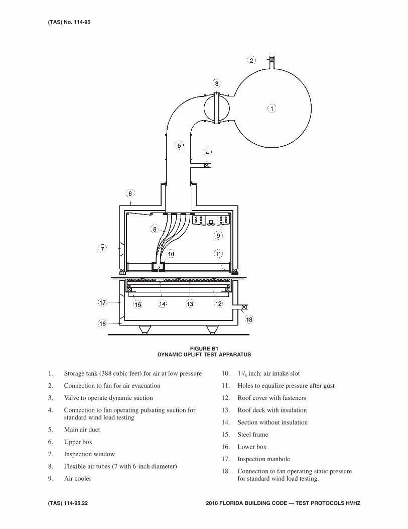
3.1 The test apparatus for determining dy-namic wind-load resistance is shown inFigure B1, herein.
Test Limitations and Precautions:4.
4.1 Testing under this test method is limited tomechanically attached roof system as-semblies having a fastener row spacingnot greater than 72 inches.
4.2 During the test, all testing agency repre-sentatives and other test observers shallwear ear and eye protection and hard hatsto prevent injury.
4.3 This test procedure may involve hazard-ous materials, operations and equipment.This protocol does not purport to addressall of the safety problems associated withits use. It is the responsibility of the user toconsult and establish appropriate safetyand health practices and determine the ap-plicability of regulatory limitations priorto use.
2010 FLORIDA BUILDING CODE — TEST PROTOCOLS HVHZ (TAS) 114-95.19
TESTING APPLICATION STANDARD (TAS) 114-95APPENDIX B
TEST PROCEDURE FOR SIMULATED DYNAMIC UPLIFT PRESSURE RESISTANCEOF MECHANICALLY ATTACHED ROOF SYSTEM ASSEMBLIES
Test Specimens:5.
5.1 The test specimen(s) shall be constructedin compliance with the manufacturer’scurrent, published installation specifica-tions and details for the roof system as-sembly under consideration for approval.If the fastener density or spacing for theroof system assembly varies, those havingthe lowest number of attachment pointsshall be tested.
5.2 Roof system assemblies whose wind-loadresistance performance may be affectedby bad weather conditions during installa-tion shall be constructed in a mannerwhich simulates actual working condi-tions.
Test Procedure:6.
6.1 Principal:
6.1.1 The roof system assembly testspecimen is mounted between twoair-tight boxes. A pressure differ-ence is applied across the testspecimen. Subsequent increasingpressure differences are applieduntil failure occurs.
6.2 A constant, positive static pressure (P) of15 psf (718 Pa) shall be applied to the un-derside of the test specimen during all dy-namic pressure intervals. This constant,positive static pressure shall be appliedfrom the lower box of the test apparatus.See Figure B1, herein.
6.3 The dynamic pressure (Pd) is applied asgusts of suction in a 11/8 inches (30 mm)slit positioned above the roof cover andbetween fastener rows where insulationhas been removed, resulting in initial up-
ward deflection of the roof cover andnon-axial loading at attachment points.
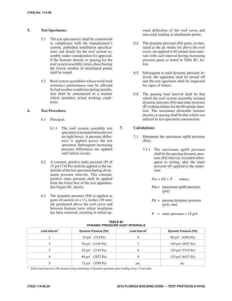
6.4 The dynamic pressure (Pd) gusts, as mea-sured at the air intake slit above the roofcover, are applied in 60 minute time inter-vals with each interval having increasingpressure gusts as noted in Table B1, be-low.
6.5 Subsequent to each dynamic pressure in-terval, the apparatus shall be turned offand the test specimen shall be inspectedfor signs of failure.
6.6 The passing load interval shall be thatwhich the roof system assembly resisteddynamic pressure (Pd) and static pressure(P) without failure for the 60 minute dura-tion. The maximum allowable fastenerdensity or spacing shall be that which wasutilized in test specimen construction.
Calculations:7.
7.1 Determine the maximum uplift pressure(Pm):
7.1.1 The maximum uplift pressureshall be the passing dynamic pres-sure (Pd) interval, recorded subse-quent to testing, plus the staticpressure (P) applied to the under-side.
where,Pm = Pd + P
Pm = maximum uplift pressure(psf);
Pd = passing dynamic pressure(psf); and,
P = static pressure = 15 psf.
(TAS) 114-95.20 2010 FLORIDA BUILDING CODE — TEST PROTOCOLS HVHZ
(TAS) No. 114-95
TABLE B1DYNAMIC PRESSURE GUST INTERVALS
Load Interval1 Dynamic Pressure (Pd) Load Interval1 Dynamic Pressure (Pd)
1 15 psf (718 Pa) 6 90 psf (4309 Pa)
2 30 psf (1436 Pa) 7 105 psf (5027 Pa)
3 45 psf (2154 Pa) 8 120 psf (5745 Pa)
4 60 psf (2872 Pa) 9 135 psf (6437 Pa)
5 75 psf (3590 Pa) etc. etc.1 Each load interval is 60 minutes long consisting of dynamic pressure gust loading every 15 seconds.
7.2 Determine the fastener assembly designvalue (dv) using the maximum uplift pres-sure (Pm), achieved during testing, andthe maximum allowable fastener densityor spacing utilized for test specimen con-struction.
where,dvPm l w
n= × ×
dv = fastener assembly design value(lbf);
Pm = maximum uplift pressure (psf);
l = length of test specimen (ft);
w = width of test specimen (ft); and,
n = number of fasteners.
Interpretation of Results:8.
8.1 The maximum allowable fastener densityor spacing utilized for test specimen con-struction relates directly to the maximumuplift pressure (Pm), determined in Sec-tion 7.1.
8.2 A 2:1 margin of safety shall be applied tothe maximum uplift pressure (Pm) deter-mined in Section 7.1.
8.3 The fastener assembly design value (dv)determined from dynamic uplift testingmay be used to alter the maximum allow-able fastener density or spacing throughdata extrapolation, in compliance withRAS 137 (for single-ply membrane at-tachment), to meet design pressures for aspecific building. Only “upward” extrap-olation is acceptable (i.e. fastener densitymay not be decreased and fastener spac-ing may not be increased for lesser designpressures).
Report:9.
9.1 The final test report shall include the fol-lowing:
9.1.1 A description of the roof systemassembly test specimen, includingthe manufacturer of all compo-nents, a description of all compo-nents and the method of testspecimen construction (includingthe fastener density or spacing).
9.1.2 A copy of the published applica-tion instructions provided by theroof system assembly manufac-turer.
9.1.3 A description of the test appara-tus.
9.1.4 A record of all observations notedduring inspections subsequent toeach dynamic pressure interval,including the final mode of fail-ure.
9.1.5 The dynamic pressure interval,and time within the interval, atwhich the test specimen failed. Iffailure was not observed until theend of the dynamic pressure inter-val, record only the “failure inter-val.”
9.1.6 A copy of the calculations fromSection 7 and the results thereof.
2010 FLORIDA BUILDING CODE — TEST PROTOCOLS HVHZ (TAS) 114-95.21
(TAS) No. 114-95
(TAS) 114-95.22 2010 FLORIDA BUILDING CODE — TEST PROTOCOLS HVHZ
(TAS) No. 114-95
1. Storage tank (388 cubic feet) for air at low pressure
2. Connection to fan for air evacuation
3. Valve to operate dynamic suction
4. Connection to fan operating pulsating suction forstandard wind load testing
5. Main air duct
6. Upper box
7. Inspection window
8. Flexible air tubes (7 with 6-inch diameter)
9. Air cooler
10. 11/8 inch: air intake slot
11. Holes to equalize pressure after gust
12. Roof cover with fasteners
13. Roof deck with insulation
14. Section without insulation
15. Steel frame
16. Lower box
17. Inspection manhole
18. Connection to fan operating static pressurefor standard wind load testing.
FIGURE B1DYNAMIC UPLIFT TEST APPARATUS
Scope:1.
1.1 Damage incurred by the effects of windover and internal pressure under a totallyadhered, partially adhered or mechani-cally attached roof system assembly gen-erally results in one or more of thefollowing:
• Uplift of the cover (when totally ad-hered);
• Delamination within the roof insu-lation cover (when totally or par-tially adhered);
• Failure of adhesive between theinsulation and the deck or betweenthe insulation and the vapor retarderand/or between the vapor retarderand the deck; and,
• Failure of the fastener/substrate,fastener/insulation or fastener/roofcover combination.
1.2 Thus the nature of the damage incurredwould suggest that an instrument de-signed to measure the stability of roof as-semblies be equipped to evaluate bondstrength indicated in the items above. TheUplift Pressure Test has been designed forthis purpose.
1.3 This procedure is not applicable to me-chanically attached roof system assem-blies having a batten or fastener rowspacing greater than 48 inch (1.2 m) o.c.or a spot/grid attachment density greaterthan 8 square feet (0.7432 m2) per fas-tener.
Terminology–the following definitions applyto the test procedure outlined herein.
2.
2.1 Failure: Roof system assembly failure un-der this test standard could be one or moreof the following:
• withdrawal or breakage of fasteners;
• tearing, splitting or other breakageof the roof cover at the point(s) of at-tachment;
• impairment of the waterproofingfunction of the roof systems assem-bly (i.e. cracking of componentswithin the assembly);
• permanent deformation of the roofcover or fastener assembly, includ-ing stress plate, which may reducethe waterproofing function of theroof system assembly over time;and,
• delamination or separation of ad-hered areas.
Apparatus:3.
3.1 The uplift pressure apparatus is a steelpressure vessel arranged to supply airpressure at pre-established standard ratesto the underside of the roof system assem-bly test specimen which forms the top ofthe test apparatus.
3.2 The pressure vessel measures 9 feet longby 5 feet wide by 2 inches deep (2.7 m by1.5 m by 51 mm) (See Figures C1 and C2,herein).
3.3 A 3/4 inch (19 mm) opening is supplied inone 9 foot (2.7 m) side for an air supply in-let. A 1/4 inch (6 mm) opening in the oppo-site 9 foot (2.7 m) side serves as amanometer connection. A rubber gasketthat lies between the top angle of the pres-sure vessel and the test assembly mini-mizes air leakage when the sample isclamped on.
3.4 Air pressure is supplied through the use ofan air compressor (5 horse power electricmotor, 1200 rpm) in conjunction with a 21foot (6.4 m) section of 12 inch (305 mm)pipe which serves as a reservoir. Pressurereadings are obtained from a water-filled,or other type of, manometer, calibrated toread directly in pounds per square foot(kg/m2).
2010 FLORIDA BUILDING CODE — TEST PROTOCOLS HVHZ (TAS) 114-95.23
TESTING APPLICATION STANDARD (TAS) 114-95APPENDIX C
TEST PROCEDURE FOR SIMULATED UPLIFT PRESSURE RESISTANCE OFROOF SYSTEM ASSEMBLIES
Test Limitations and Precautions:4.
4.1 During the test, all testing agency repre-sentatives and other test observers shallwear ear and eye protection and hard hatsto prevent injury.
4.2 This test procedure may involve hazard-ous materials, operations and equipment.This protocol does not purport to addressall of the safety problems associated withits use. It is the responsibility of the user toconsult and establish appropriate safetyand health practices and determine the ap-plicability of regulatory limitations priorto use.
Test Specimens:5.
5.1 The components for a proposed test panelare assembled to the desired specifica-tions and details (gauge of steel, applica-tion method and rate for the adhesives orfasteners, size and thickness of insulation,type of cover) and then left to “cure” for aspecified time period.
5.1.1 Test specimens assembled in hotasphalt shall be allowed to cure fornot less than 24 hours prior to test-ing.
5.1.2 Test specimens assembled in coldadhesive shall be allowed to curefor not less than 28 days prior totesting, with the exception of thepreliminary four day testing notedin Section 8.3.1.2 of TAS 114.
5.1.3 Test specimens assembled overlightweight concrete deck sub-strates shall be constructed sevendays after the deck is poured andshall be tested on the 28th day.
5.2 If the test specimen is a totally or partiallyadhered roof system assembly, the testspecimen shall be tested to 30 psf (1.4kPa) after a 4 day laboratory cure time atambient conditions. If the test specimenfails to resist this initial test pressure, thetest shall be discontinued. Upon passingthis initial testing, the test specimen shallbe allowed to cure for the remaining curetime.
5.3 When ready for testing, the panel isplaced on top of the uplift pressure appa-
ratus. A 7/8 inch (22 mm) thick, 2 inch (51mm) wide board is placed around the per-imeter of the sample followed by 2 inchby 3 inch (51 mm by 76 mm) metal angles(smaller dimension horizontal). FiveC-clamps are securely attached on each 9feet (2.7 m) edge three along each 5 foot(1.4 m) edge. The appropriate hose con-nections are then made to the air supplyand manometer.
5.4 Not less than three test specimens shall beconstructed for each roof system assem-bly being tested.
5.5 Roof system assemblies whose wind-loadresistance performance may be affectedby bad weather conditions during installa-tion shall be constructed in a mannerwhich simulates actual working condi-tions.
Test Procedure:6.
6.1 Principal:
6.1.1 The roof system assembly testspecimen is mounted on the testapparatus. A pressure differenceis applied across the test speci-men. Subsequent increasing pres-sure differences are applied untilfailure occurs. Three roof systemassembly test specimens shall betested and the average passingload reported.
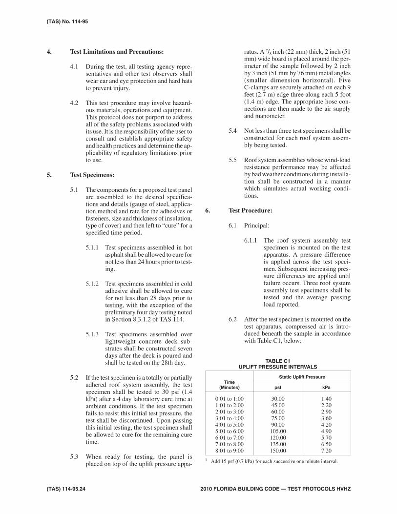
6.2 After the test specimen is mounted on thetest apparatus, compressed air is intro-duced beneath the sample in accordancewith Table C1, below:
(TAS) 114-95.24 2010 FLORIDA BUILDING CODE — TEST PROTOCOLS HVHZ
(TAS) No. 114-95
TABLE C1UPLIFT PRESSURE INTERVALS
Time(Minutes)
Static Uplift Pressure
psf kPa
0:01 to 1:001:01 to 2:002:01 to 3:003:01 to 4:004:01 to 5:005:01 to 6:006:01 to 7:007:01 to 8:008:01 to 9:00
30.0045.0060.0075.0090.00105.00120.00135.00150.00
1.402.202.903.604.204.905.706.507.20
1 Add 15 psf (0.7 kPa) for each successive one minute interval.
6.3 Prior to and during the attainment of theuplift pressures noted above, the test spec-imen is examined for failure. Upon fail-ure, the test specimen is dismantled andexamined to determine the exact mode offailure.
6.4 Record the mode, time and pressure inter-val of failure.
6.5 Repeat Sections 6.2 through 6.4 for eachof three test specimens.
Interpretation of Results:7.
7.1 The passing uplift pressure shall be theaverage of the three pressures which thetest specimens resisted for one minutewithout failure. If one or more of the threetests yields a passing uplift pressuregreater or less than 15 percent of other re-corded values, an additional test shall beconducted.
7.2 The minimum passing uplift pressure foran approved roof system assembly shallbe 90 psf (4.2 kPa).
7.3 A 2:1 margin of safety shall be applied tothe passing uplift pressure prior to inclu-sion in the system manufacturer’s ProductApproval.
7.4 Average wind velocities can vary consid-erably from area to area. The FloridaBuilding Code, Building utilizes awindspeed as noted in Section 1620.2.These wind velocities in miles per hourare related to the design pressure, inpounds per square feet (kg/m2), for a par-ticular building. Refer to Chapter 16(High-Velocity Hurricane Zones) of theFlorida Building Code, Building andASCE 7.
7.5 No extrapolation of resulting data will beaccepted.
7.6 Design pressures calculated in accor-dance with ASCE 7 are permitted to bemultiplied by 0.6 for the purposes of com-paring to tested pressures in TAS 114.
Report:8.
8.1 The final test report shall include the fol-lowing:
8.1.1 A description of the roof systemassembly test specimen, includingthe manufacturer of all compo-nents, a description of all compo-nents and the method of testspecimen construction (includingthe fastener density or spacingand/or asphalt or adhesive appli-cation rate).
8.1.2 A copy of the published applica-tion instructions provided by theroof system assembly manufac-turer.
8.1.3 A description of the test appara-tus.
8.1.4 A record of all observations notedduring each test during each pres-sure interval, including the finalmode(s) of failure.
8.1.5 The pressure interval, and timewithin the interval, at which eachtest specimen failed.
8.1.6 The passing uplift pressure foreach test specimen and the calcu-lated average passing uplift pres-sure from the three tests. Ifadditional tests are conducted tomaintain the +15 percent criteria,record results from all additionaltesting.
2010 FLORIDA BUILDING CODE — TEST PROTOCOLS HVHZ (TAS) 114-95.25
(TAS) No. 114-95

(TAS) 114-95.26 2010 FLORIDA BUILDING CODE — TEST PROTOCOLS HVHZ
(TAS) No. 114-95
FIGURE C1UPLIFT PRESSURE TEST APPARATUS
FIGURE C2UPLIFT PRESSURE TEST SPECIMEN MOUNTED IN TEST

Scope:1.
1.1 In situations where the uplift pressure testprocedure described in Appendix B, C orJ is not applicable, especially for liq-uid/spray applied roof constructions, thefollowing test procedure may be used asan alternate method for evaluation of up-lift resistance of the roof construction.
Terminology–the following definitions applyto the test procedure outlined herein.
2.
2.1 Failure = roof system assembly failureunder this test standard could be one ormore of the following:
• tearing, splitting or other breakageof the roof cover;
• impairment of the waterproofingfunction of the roof systems assem-bly (i.e. cracking of componentswithin the assembly);
• permanent deformation of the roofcover, which may reduce the water-proofing function of the roof systemassembly over time; and,
• delamination or separation of ad-hered areas.
Apparatus:3.
3.1 The uplift pressure apparatus is a 2 foot by2 foot by 11/2 inch (0.6 m by 0.6 m by 39mm) plywood square containing a cen-trally located eyebolt secured to the top ofthe test panel. The plywood square isbonded to the top surface of the roof sys-tem assembly test specimen.
3.2 A load cell, or other force sensing device,is positioned in line and connected to theeyebolt. The opposite end of the load cellis attached to a chain-hoist assembly.Prior to testing, the load cell shall be cali-brated such that the downward force in-curred by the test apparatus mass iseliminated from recorded load values.
3.2 A minimum 2 inch (51 mm) wide strip iscut around and adjacent to the perimeterof the plywood down through the insula-tion to the deck.
Test Limitations and Precautions:4.
4.1 During the test, all testing agency repre-sentatives and other test observers shallwear ear and eye protection and hard hatsto prevent injury.
4.2 This test procedure may involve hazard-ous materials, operations and equipment.This protocol does not purport to addressall of the safety problems associated withits use. It is the responsibility of the user toconsult and establish appropriate safetyand health practices and determine the ap-plicability of regulatory limitations priorto use.
Test Specimens:5.
5.1 The components for a proposed test panelare assembled to the desired specifica-tions and details (gauge of steel, applica-tion method and rate for the adhesives,size and thickness of insulation, type ofcover) and then left to “cure” for a speci-fied time period.
5.2 The test specimen shall be tested to 30 psf(1.4 kPa) after a 4 day laboratory curetime at ambient conditions. If the testspecimen fails to resist this initial testpressure, the test shall be discontinued.On passing this initial testing, the testspecimen shall be allowed to cure for theremaining cure time.
5.3 If insulation panels for part of the testspecimen, a panels shall be installed suchthat a three way joint is located in the cen-ter of the test specimen. If more than onelayer of insulation forms part of the testspecimen, the top layer shall employ thethree way joint.
2010 FLORIDA BUILDING CODE — TEST PROTOCOLS HVHZ (TAS) 114-11.27
TESTING APPLICATION STANDARD (TAS) 114-95APPENDIX D
TEST PROCEDURE FOR SIMULATED UPLIFT PRESSURE RESISTANCE OFADHERED ROOF SYSTEM ASSEMBLIES

5.4 Roof system assemblies whose wind-loadresistance performance may be affectedby bad weather conditions during installa-tion shall be constructed in a mannerwhich simulates actual working condi-tions.
5.5 Not less than three test specimens shall beconstructed for each roof system assem-bly being tested.
Test Procedure:6.
6.1 Principal
6.1.1 The test apparatus is secured tothe roof system assembly testspecimen which is cut around theperimeter of the test apparatus.Thereafter, an uplift load is ap-plied to the test apparatus whichdistributes the load over its area.The distributed load is transferredto the test specimen. Subsequentincreasing uplift loads are applieduntil failure occurs.
6.2 Once the test specimen has cured and thetest apparatus is secured, uplift loads areapplied through the test apparatus in ac-cordance with Table D1, below:
6.3 Prior to and during the attainment of theuplift pressures noted above, the test spec-imen is examined for failure. On failure,the test specimen is dismantled and exam-ined to determine the exact mode of fail-ure.
6.4 Record the mode, time, and pressure in-terval of failure.
Interpretation of Results:7.
7.1 The passing uplift pressure shall be theaverage of the three pressures which thetest specimens resisted for one minutewithout failure. If one or more of the threetests yields a passing uplift pressuregreater or less than 15 percent of other re-corded values, an additional test shall beconducted.
7.2 The minimum passing uplift pressure foran approved roof system assembly shallbe 90 psf (4.2 kPa).
7.3 A 2:1 margin of safety shall be applied tothe passing uplift pressure prior to inclu-sion in the system manufacturer’s ProductApproval.
7.4 Average wind velocities can vary consid-erably from area to area. The FloridaBuilding Code, Building utilizes awindspeed as noted in section 1620.2.These wind velocities in miles per hourare related to the design pressure, inpounds per square feet (kg/m2), for a par-ticular building. Refer to Chapter 16(High-Velocity Hurricane Zones) of theFlorida Building Code, Building andASCE 7.
7.5 No extrapolation of resulting data will beaccepted.
Report:8.
8.1 The final test report shall include the fol-lowing:
8.1.1 A description of the roof systemassembly test specimen, includingthe manufacturer of all compo-nents, a description of all compo-nents and the method of testspecimen construction.
(TAS) 114-11.28 2010 FLORIDA BUILDING CODE — TEST PROTOCOLS HVHZ
(TAS) No. 114-11
APPARATUS TABLE D1UPLIFT LOAD INTERVALS AND CORRESPONDING PRESSURES
Time(Minute)
Load Pressure
lbf N psf kPa
0:01 to 1:001:01 to 2:002:01 to 3:003:01 to 4:004:01 to 5:005:01 to 6:006:01 to 7:007:01 to 8:008:01 to 9:00
120180240300360420480540600
5348011067133416011868213524022670
3045607590105120135150
1.42.22.93.64.24.95.76.57.2
1 Add 60 lbf (N) from each successive one minute interval.
8.1.2 A copy of the published applica-tion instructions provided by theroof system assembly manufac-turer.
8.1.3 A description of the test apparatus.
8.1.4 A record of all observations notedduring each pressure interval, in-cluding the final mode of failure.
8.1.5 The pressure interval, and timewithin the interval, at which thetest specimen failed.
2010 FLORIDA BUILDING CODE — TEST PROTOCOLS HVHZ (TAS) 114-11.29
(TAS) No. 114-11

(TAS) 114-11.30 2010 FLORIDA BUILDING CODE — TEST PROTOCOLS HVHZ

Scope:1.
1.1 The corrosion test procedure is designedto assess the potential damage to nails,metal fasteners, batten bars and stress dis-tribution plates used for mechanically at-tached roof covers and/or attachment ofinsulation. There is no single test proce-dure that approximates all climactic con-di t ions exper ienced by roofingcomponents; however, tests are availablethat provide an indication of potential re-sistance to corrosion.
1.2 All nails and carbon steel fasteners shallbe tested for corrosion resistance in com-pliance with ASTM Standard Practice G85 [(Modified Salt Spray (Fog) Testing)],Annex A5 (Dolute Electrolyte CyclicFog/Dry Testing) as modified for theFlorida Building Code, Building andnoted in Section 2, herein.
1.3 All batten bars, stress distribution plates,and other metal fastener types shall betested for corrosion resistance in compli-ance with DIN 50018 as noted in Section3, herein.
ASTM G 85–All nails and carbon steel fasten-ers shall be tested for corrosion resistance incompliance with ASTM Standard Practice G 85except as noted below.
2.
2.1 Salt solution:
2.1.1 The salt solution shall consist ofan electrolyte solution of 0.05percent sodium chloride and 0.35percent ammonium sulfate bymass.
2.1.2 The water and sodium chlorideshall meet the purity requirementsof Section 6 of ASTM G 85. Theammonium sulfate shall containnot more than 0.3 percent total im-purities.
2.2 Conditions in the salt fog chamber:
2.2.1 One cycle shall consist of 1 hourfog followed by 1 hour dry-off.
2.2.2 During the fog period, the cham-ber shall be at ambient room con-ditions [(i.e. 75 + 6°F (24 + 3°C)].
2.2.3 During the dry-off period, thetemperature throughout the expo-sure zone shall reach and remainat 95 + 3°F (35 + 1.5°F) within 3/4
hour of switching from the fog pe-riod to the dry period.
2.2.3.1 The dry-off shall beachieved by purgingthe chamber with freshair, such that within 3/4
hour all visible mois-ture is dried off thespecimens.
2.2.3 The pH of the collected solutionshall range between 5.0 and 5.4,as measured in compliance withASTM E 70.
2.3 Saturation Tower:
2.3.1 This test does not use humidifiedair; therefore, one of the followingmethods shall be utilized to avoidhumidifying the air.
• Empty the saturation towerand ensure that the tower heat-ers are tuned off; or,
• Arrange the spray plumbingso that the atomizing air doesnot go through the saturationtower, but goes directly to thespray nozzle.
2010 FLORIDA BUILDING CODE — TEST PROTOCOLS HVHZ (TAS) 114-95.31
TESTING APPLICATION STANDARD (TAS) 114-95APPENDIX E
TEST PROCEDURE FOR CORROSION RESISTANCE OF FASTENERS,BATTEN BARS AND STRESS DISTRIBUTION PLATES

2.4 Atomization and quantity of fog:
2.4.1 Collect the fog in a special contin-uous spray run of at least 16 hours,performed between test runs. Theregular spray periods of 1 hour arenot long enough for collectingsufficient fog to make accurate de-terminations of deposition rate.See Section 4.3.2 of ASTM G 85for instructions on fog collection.
2.5 Cabinet modification:
2.5.1 In order to achieve the tempera-ture changes for this test, modifi-cations or additions to the ASTMTest Standard B 117 apparatusmay be required. These may in-clude modifications to:
• exposure chamber;
• temperature controls;
• air flow apparatus;
• insulation; and,
• means for conditioning theheated air in the chamber orwater in the jacket.
2.5.2 Two manufacturers of cabinetswhich meet the needs of this testare:
• Arotech—Cleveland, Ohio
• Q Panel—Cleveland, Ohio
2.5.3 Consult the cabinet manufacturerfor any additional information orsuggestions for cabinet modifica-tion to meet the needs of this test.
2.6 Period of time:
2.6.1 The acetic acid-salt spray (fog)test shall be conducted for 140 cy-cles for nails and 180 cycles forcarbon steel fasteners, where onecycle consists of 1 hour fog and 1hour dry-off. Continuous opera-tion implies that the chamber beclosed except for the short dailyinterruptions necessary to inspect,rearrange, or remove test speci-mens, and to check and replenishthe solution in the reservoir.Schedule operations so that these
interruptions are held to a mini-mum.
2.6.1.1 Any test specimenwhich exhibits corro-sion on an area in ex-cess of 5 percent of itstotal surface area shallbe considered as failingthe corrosion resis-tance test. It shall be theresponsibility of thetesting agency repre-sentative to conduct anobjective visual exami-nation of the test speci-men regarding i tspercentage of corrodedor rusted area.
2.6.2 As an alternate, the test specimenmay be tested along side a “con-trol” specimen consisting of“wire,” of similar type and diame-ter as the test specimen, which iszinc-coated (galvanized), in com-pliance with ASTM A 641, to azinc-coating weight of not lessthan 0.28 ounces per square feet(0.00073 kg/m2), as measured incompliance with ASTM A 90.
2.6.2.1 The test specimen andcontrol specimen(noted in Section 2.4.2)shall be tested concur-rently until:
• The test specimen exhibitsvisually notable signs ofcorrosion while the controlspecimen does not;
• The control specimen ex-hibits visually notablesigns of corrosion whilethe test specimen does not;or,
• If the test and control spec-imens exhibit equivalentsigns of corrosion duringthe test, the test shall con-tinue for 140 continuouscycles.
2.6.2.2 Any test specimenwhich exhibits visuallynotable signs of corro-
(TAS) 114-95.32 2010 FLORIDA BUILDING CODE — TEST PROTOCOLS HVHZ
(TAS) No. 114-95

sion prior to the controlspecimen shall be con-sidered as failing thecorrosion resistancetest. It shall be the re-sponsibil i ty of thetesting agency repre-sentative to conduct anobjective visual exami-nation of the test andcontrol specimens re-garding corrosion orrusting.
2.6.2.3 If it becomes necessaryto test for the full 140cycles, the criteria shallbe as noted in Section2.6.1.1.
2.6.3 The cabinet manufacturer Q Panel(Cleveland, Ohio), noted above,also provides metal wire samplesof various diameters which arecoated and measured in compli-ance with Section 2.6.2 and can beused as control specimens.
DIN 50018–All batten bars, stress distributionplates, and other fastener types shall be testedfor corrosion resistance in compliance with DIN50018.
3.
3.1 Duplicate tests are conducted in accor-dance with the DIN 50018 StandardKesternick Test (2.01) on samples pre-pared first with fasteners (other than nails)installed in: 1) minimum 22 gage steeldeck; 2) minimum 3000 pounds persquare inch (20 685 kPa) concrete; or, 3)minimum 3/4 inch thick plywood (whereapplicable).
3.2 For concrete and plywood samples, thefasteners are removed from the substratebefore testing. Each sample is subjectedto 15 cycles of exposure. Batten bars andplates shall also meet these requirements.
3.3 Evaluation of DIN 50018 results:
3.3.1 The fastener, stress distributionplate and/or batten bar shall notshow more than 15 percent of thesurface area rusted. Coatings cov-ering these components shall notblister, peel or crack. It shall be theresponsibility of the testing
agency representative to conductan objective visual examination ofthe test specimen regarding itspercentage of corroded or rustedarea and/or the degradation of anycoatings.
2010 FLORIDA BUILDING CODE — TEST PROTOCOLS HVHZ (TAS) 114-95.33
(TAS) No. 114-95

(TAS) 114-95.34 2010 FLORIDA BUILDING CODE — TEST PROTOCOLS HVHZ
Scope:1.
1.1 Simulated hail damage test proceduresare designed to assess the potential fordamage to roof system assemblies whenadhered directly to insulation, lightweightconcrete roof decks, structural concreteroof decks, gypsum decks or fire-treatedwood roof decks. The procedures weredeveloped to determine the potential forpuncture of the roof cover resulting fromhail storms when the roof cover is appliedover its tested substrate within an ap-proved assembly.
1.2 Due to the variable severity of potentialdamage resulting from hail storms in dif-ferent geographic areas, two separate haildamage tests are used. The tests yield rat-ings identified as Class “SH” (Severe HailDamage Resistant) and Class “MH”(Moderate Hail Damage Resistant).
Description of Test Apparatus:2.
2.1 Class “SH”—The test apparatus consistsof a plastic tube 2 inches (51 mm) insidediameter, supported above the sample. Asteel ball 13/4 inch (45 mm) in diameter,weighing 0.79 pounds (3.5 N) is droppedfrom a height of 17 feet 91/2 inches (5.4 m)onto the sample. This procedure is re-peated 10 times on various sections of thesample. This procedure generates an im-pact energy of approximately 14 poundsper feet (19 J) over the impact area of a13/4 inch (45 mm) diameter ball.
2.2 Class ‘MH’-The test apparatus consists ofa steel tube 21/4 inches (57 mm) inside di-ameter supported vertically above thesample by a tripod. Holes are drilled in thesteel tube to allow the release mechanismto be adjusted for the proper drop height.A steel ball 2 inches (51 mm) in diameter,weighing 1.625 pounds (737 g) isdropped from a height of 5 feet (1.5 m)through the tube onto the sample. Thisprocedure is repeated 10 times on varioussections of the sample. This procedure
generates an energy of approximately 8pounds per feet (10.8 J) over the impactarea of a 2 inch (51 mm) diameter ball.
Test Procedure:3.
3.1 Two identical roof cover samples, 2 feetby 4 feet (0.6 m by 1.2 m) are selectedfrom the material to be tested. The firstsample is prepared with the roof cover ap-plied to the selected insulation sub-strate(s) or adhered directly to theappropriate roof deck in accordance withthe manufacturer’s specifications. Afterpreparation, the sample is conditioned forup to 28 days (laboratory cure). For mate-rials supplied as sheets or rolls, the sampleshall incorporate a field seam within theassembly, in the center and running paral-lel to the 4 foot (1.2 m) side. The secondsample is loose laid over the matchingsubstrate or roof deck. Both samples aresubjected to initial testing. The 13/4 inch(45 mm) diameter steel ball is droppedonto the sample from a height of 17 feet91/2 inches (5.4 m) for a Class “SH” rating,or the 2 inch (51 mm) diameter ball isdropped onto the sample from a height of5 feet (1.5 m) for a Class “MH” rating. Aminimum of ten drops of the impactor isrequired, five of which shall be on thefield-fabricated seam, if appropriate. Thesamples are then removed and inspectedfor damage.
3.2 A piece of loose laid sample 12 inch by 24inch (305 mm by 610 mm) is cut from theoriginal sample, and then further condi-tioned (weathered) for 1000 hours in afluorescent ultraviolet condensation-typeweathering apparatus using the ASTM G53 Test Method. After weathering, the im-pact test procedure is repeated. The sam-ple is then removed and inspected fordamage.
Evaluation of Results:4.
4.1 The roof cover shall not show any signs ofcracking or splitting. The field seam shall
2010 FLORIDA BUILDING CODE — TEST PROTOCOLS HVHZ (TAS) 114-95.35
TESTING APPLICATION STANDARD (TAS) 114-95APPENDIX F
TEST PROCEDURE FOR SUSCEPTIBILITY TO HAIL DAMAGEFOR ROOF SYSTEM ASSEMBLIES

not show any signs of cracking, splitting,or separation or rupture when examinedclosely under a 10x magnification. Thecover thickness shall be checked at thepoints of impact.
(TAS) 114-95.36 2010 FLORIDA BUILDING CODE — TEST PROTOCOLS HVHZ
(TAS) No. 114-95
Scope:1.
1.1 The Susceptibility to Leakage Test Proce-dure is designed to assess the potential forwater migration when the cover is fabri-cated with a typical lap seam or perimeterdetail.
Description of Test Apparatus2.
2.1 The test apparatus consists of top and bot-tom sections that are bolted together withthe specimen being evaluated placed as adiaphragm between the sections. The topsection consists of a 91/4 inch (203 mm)diameter cap which has two 1/2 inch (13mm) diameter threaded inlet holes. Thistop cap is cemented to a 53/4 inch (146mm) length of 73/4 inch (1197 mm) diam-eter clear acrylic pipe which is cementedto an 115/8 inch (295 mm) diameter pipeflange. The bottom section consists of a91/4 inch (235 mm) cap which has two 1/2
inch (13 mm) diameter threaded inletholes. The bottom cap is cemented to a57/8 inch (149 mm) length of 73/4 inch (197mm) diameter clear acrylic pipe which iscemented to an 115/8 inch (295 mm) diam-eter pipe flange.
2.2 Both top and bottom sections are boltedtogether at the flanges with the cover be-ing evaluated between them. The top andbottom caps are fabricated to allow astanding head of water above and addi-tional air pressure above and below. Eachsection is fabricated with two 1/2 inch (13mm) diameter pipe outlets to allow con-nection of an air pressure inlet and pres-sure gauge.
Test Procedure:3.
3.1 An 18 inch (457 mm) diameter sample isprepared with the roof cover. This speci-men is prepared with a field seam and/orpenetration detail included and runningalong the diameter of the sample. Thecompleted sample is conditioned (weath-
ered) for 288 hours (minimum) in an Ul-traviolet Weatherometer before being cutto a 10 inch (254 mm) diameter size.
3.2 The 10 inch (254 mm) diameter specimenis then bolted in place between the flangesof the test apparatus. Water is then placedover the sample to a depth of 6 inches (152mm) and maintained for a period of 7days. At the end of the 7 day period, air isintroduced below the water to a 1 poundper square inch (6.8 kPa) level and cycled25 times from 1 pounds per square inch(6.8 kPa) level and cycled 25 times from 1pounds per square inch (6.8 kPa) to ambi-ent.
Evaluation of Results:4.
4.1 There shall be no signs of water leakageduring the 7 day period. In addition, thereshall be no signs of water leakage duringor after the pressure cycles.
2010 FLORIDA BUILDING CODE — TEST PROTOCOLS HVHZ (TAS) 114-95.37
TESTING APPLICATION STANDARD (TAS) 114-95APPENDIX G
TEST PROCEDURE FOR SUSCEPTIBILITY TO LEAKAGEFOR ROOF SYSTEM ASSEMBLIES

(TAS) 114-95.38 2010 FLORIDA BUILDING CODE — TEST PROTOCOLS HVHZ
Scope:1.
1.1 The following series of small scale testsare designed to allow monitoring of qual-ity controls exercised in the manufactureof single-ply roof covers and/or to charac-terize individual materials. In addition,they may be used to assess certain physi-cal characteristics necessary for the con-tinued performance of a cover assemblywhen installed within a construction. Itmay not be appropriate to require all testsfor each construction. A preliminary deci-sion shall be made as to which tests will berequired. The decision will be based onseveral factors: e.g., (a) from what basicmaterial or polymer is the roof membranefabricated; (b) how is the roof membraneapplied; (c) how is the roof membrane se-cured; (d) to what substrates is the roofmembrane applied, etc.
Delamination Test:2.
2.1 The roof membrane is applied to the topsurface of an insulation sample in accor-dance with the manufacturer’s specifica-tions and allowed to cure for the specifiedperiod of time, maximum 28 days. Thisassembly is then cut into 6 inch by 6 inch(152 mm by 152 mm) pieces prior to as-sembly of the test specimen. Plywood, 6inch by 6 inch by 3/4 inch (152 mm by 152mm by 19 mmm), is adhered to the topand bottom surface of the prefabricatedspecimen with a compatible adhesive. Asteel plate, 6 inch by 6 inch by 1/2 inchthick (152 mm by 152 mm by 13 mm), isfastened to the plywood facers with four#12, 11/4 inch diameter by 6 inch (152mm) long bolts on each plate. Force is ex-erted in a direct line parallel to the shankof the bolt at a constant machine speed of2 inch (51 mm) per minute. A minimumof three tests must be conducted on eachselected substrate. The ultimate averageload of failure is then determined.
Peel Test (ASTM D 1781):3.
3.1 The roof membrane is applied to the topsurface of an insulation sample in accor-dance with the manufacturer’s specifica-tions such that a minimum 1 inch (25 mm)extends beyond the edge of the rigid insu-lation after cutting and trimming. The top3 inches (76 mm) of the cover is not ad-hered to the insulation substrate. The sam-ple is allowed to cure for the specifiedtime, maximum 28 days. The assembly iscut into 3 inch (76 mm) by 12 inch (305mm) pieces with the 1 inch (25 mm) ex-cess cover at each 3 inch (76 mm) end.The top edge is held with a suitable clampand the bottom edge is clamped to the peeldrum tester.
3.2 The specimen and test apparatus are thensuspended from the top head of the testingmachine. A peel of at least 6 inches (152mm) of the cover is then made with themachine speed set at 1 inch (25 mm) perminute. A minimum of 3 tests shall beconducted on each selected substrate. Theaverage peeling load required to peel thefacing is then calculated in pound per inchof peel torque.
Tensile Test (ASTM D 1781):4.
4.1 ASTM D 638 — The roof cover is cut ac-cording to ASTM D 638 Type IV. Thespecimen is clamped into the upper andlower jaws of the tensile testing machine,with the machine speed set at 20 inchesper minute (8.5 mm/s). Determination ofstress is conducted at 100 percent, 200percent, and 300 percent elongation aswell as ultimate failure (if possible). Aminimum of 3 tests shall be conducted.
4.2 ASTM D 751 — The roof cover is fabri-cated with a field seam according to themanufacturer’s specifications before be-ing cut according to ASTM D 751 seam
2010 FLORIDA BUILDING CODE — TEST PROTOCOLS HVHZ (TAS) 114-95.39
TESTING APPLICATION STANDARD (TAS) 114-95APPENDIX H
TEST PROCEDURES FOR SMALL SCALE QC AND PHYSICAL PROPERTIES OFAPPROVED ROOF SYSTEM ASSEMBLIES
strength determination instructions. Thespecimen is clamped into the upper andlower jaws of the tensile testing machine,with the machine speed set at 12 inch perminute (5 mm/s). Determination of stressis conducted at 100 percent, 200 percent,and 300 percent elongation, as well as atultimate failure (if possible). A minimumof 3 tests shall be conducted.
(TAS) 114-95.40 2010 FLORIDA BUILDING CODE — TEST PROTOCOLS HVHZ
(TAS) No. 114-95

Scope:1.
1.1 The test procedures outlined herein coverthe maximum static and dynamic punc-ture loads which roofing membrane sam-ples can withstand without allowing thepassage of water due to puncture. Mem-brane samples are subjected to both staticand dynamic puncture loads from a rigidobject having a sharp edge to determinetheir puncture resistance performance.
1.2 This laboratory test is conducted at anydesired temperature using sheet mem-brane samples manufactured in a factoryor prepared in a laboratory.
1.3 Roof membrane samples to which themethod is applicable include bituminousbuilt-up, polymer-modified bitumen, vul-canized rubber, non-vulcanized poly-meric, and thermoplastic materials. Themethod is not applicable to aggregate-sur-faced membrane samples.
Terminology:2.
2.1 Definitions—For definitions of terms, re-fer to ASTM D 1079 or Chapter 2 andSection 1513 of the Florida BuildingCode, Building. The definitions from theFlorida Building Code, Building shalltake precedence.
Significance and Use:3.
3.1 An important factor affecting the perfor-mance of membrane roof system assem-bly is their ability to resist static and/ordynamic puncture loads. The test proce-dures outlined herein provide a means toassess static and dynamic puncture resis-tance.
3.2 The methods can be used to compare thepuncture resistance of a single type ofmembrane sample as a function of a vari-ety of insulation substrates or, conversely,to compare the resistance of a number of
membrane samples set on a single type ofinsulation.
3.3 The effect of temperature on puncture re-sistance can be studied by conducting thetest under controlled conditions usingsuch equipment as an environmentalchamber, oven, or freezer.
3.4 The methods can be useful in developingpuncture resistance performance criteriaand/or classifications for membrane roofsystem assemblies.
Apparatus:4.
4.1 Static puncture test
4.1.1 The static puncture test apparatusshall consist primarily of a mov-able rod to which a 3/8 inch (10mm) diameter ball bearing is at-tached at one end and a means forloading the specimen is attachedto the other. The static puncturetest apparatus is shown in FigureI1, herein.
4.1.2 One means for static punctureloading is to attach to the movablerod a platform on whichdeadweights are placed. Alterna-tively, pneumatic loading may beused whereby the ball bearing isattached to the movable rod andthe load is measured by an airpressure gauge which has beencalibrated against a load cell.
4.1.3 The length of the rod above thespecimen shall be not less than 3.9inch (100 mm). A framework, hav-ing a minimum width of 9.8 inches(250 mm), supports the rod per-pendicular to the surface of the testspecimen. Free vertical movementof the rod shall not be hindered bythe framework. The rod and frame-work shall be capable of support-ing loads up to 56 lbf (250 N).
2010 FLORIDA BUILDING CODE — TEST PROTOCOLS HVHZ (TAS) 114-95.41
TESTING APPLICATION STANDARD (TAS) 114-95APPENDIX I
TEST PROCEDURE FOR STATIC AND DYNAMIC PUNCTURERESISTANCE OF ROOF SYSTEM ASSEMBLIES

4.2 Dynamic puncture test:
4.2.1 The dynamic puncture test appa-ratus shall consist primarily of aheavy base, a falling arm and apuncture head. The dynamicpuncture test apparatus is shownin Figure I2, herein.
4.2.2 The falling arm shall be attachedto the base such that it can rotatefreely (e.g. using ball bearings)from a vertical to a horizontal po-sition. The length of the arm shallbe 1.7 feet (0.51 m).
4.2.3 The shape and dimensions of thepuncture head are shown in FigureI3, herein Several heads of differ-ing mass may be needed. Alterna-tively, a means of adding mass to agiven puncture head may be uti-lized. The puncture head and ad-ditional masses shall constitute acontinuous series of mass from2.2 to 22.0 pounds (1 to 10 kg) in1.1 pounds (0.5 kg) increments.The mass of the puncture head forany given test shall be within + 5percent of that selected.
4.2.4 When mounted on the rotatingarm, the face of the puncture headshall be parallel to the arm’s axisof rotation. When the puncturehead contacts the membrane sur-face, the rotating arm shall be hor-izontal.
4.2.5 The apparatus shall incorporate amechanism which allows thepuncture head to remain station-ary when in an upright position,forming an angle with the verticalof not greater than 5 degrees. Themechanism shall allow for releaseof the arm such that is falls freelyfrom gravitational forces only. Avacuum release mechanism hasbeen found suitable for this pur-pose.
4.2.6 The apparatus base, on which therotating arm and puncture headare mounted, shall be placed on ahorizontal surface such that nomovement occurs when the test is
conducted at maximum impactenergy.
4.2.7 The membrane test specimenshall be held in place over the sub-strate with a square frame havingminimum exterior and interior di-mensions of 9.8 inches (250 mm)and 7.9 inches (200 mm), respec-tively.
Test Limitations and Precautions:5.
5.1 This test procedure may involve hazard-ous materials, operations and equipment.This Protocol does not purport to addressall of the safety problems associated withits use. It is the responsibility of the user toconsult and establish appropriate safetyand health practices and determine the ap-plicability of regulatory limitations priorto use.
Test Specimens:6.
6.1 Sampling – single-ply specimens:
6.1.1 Test specimens shall be cut di-rectly from the sheet membraneand insulation materials providedfor the test using a metal templatehaving dimensions of 7.9 inchesby 7.9 inches (200 mm by 200mm), ± 5 percent.
6.2 Sampling – multi-ply specimens:
6.2.1 Test samples, having dimensionsnot less than 3 feet by 4 feet (0.9 mby 1.2 m), shall be prepared incompliance with the roof systemassembly manufacturer’s pub-lished installation instructions anddetails. The quantity of materialsin each layer shall be within + 10percent of that specified in thepublished installation instruc-tions.
6.2.2 All roofing components to be usedin the roof system assembly testspecimen shall be conditioned at77°F + 3°F (25°C + 2°C) and 50percent + 5 percent relative hu-midity for a 24 hour period priorto test sample construction.
(TAS) 114-95.42 2010 FLORIDA BUILDING CODE — TEST PROTOCOLS HVHZ
(TAS) No. 114-95
6.2.3 Test specimens shall be cut di-rectly from the constructed 3 feetby 4 feet (0.9 m x 1.2 m) test sam-ple as noted in Section 6.1.1,herein.
6.3 A minimum of 4 test specimens shall beconstructed and tested.
6.4 Unless otherwise specified, the mem-brane substrate shall be expanded poly-styrene board having a density within therange of 1.7 to 2.0 lbm/ft3 (27 to 32 kg/m3)and a thickness of 1.5 inch (38 mm), + 15percent.
Conditioning:7.
7.1 The test apparatus and test specimen shallbe conditioned at the desired temperaturefor a minimum of 8 hours prior to testing.The selected temperature shall be main-tained at + 3°F (+ 2°C) for the durationconditioning.
Test Principal:8.
8.1 Static puncture:
8.1.1 The roof system assembly testspecimen is subjected to a prede-termined static puncture load us-ing a ball bearing for a period of24 hours. The puncture loads areincreased in 2.2 lbf (10 N) incre-ments until puncture of the testspecimen occurs or until the maxi-mum load of 56 lbf (250 N) isreached. Puncture of the test spec-imen is assessed by visual exami-nation and verified by conductinga watertightness pressure test.
8.2 Dynamic puncture:
8.2.1 The Roof System Assembly testspecimen is subjected to a prede-termined dynamic puncture loadcreated by a rigid puncture headfalling through a 90 degree trajec-tory from a vertical position to ahorizontal position under gravita-tional acceleration. The impactenergy is increased from 119foot-pdl (5 J) in 59.4 foot-pdl (2.5J) increments until puncture of thetest specimen occurs or until themaximum impact energy of 1190
foot-pdl (50 J) is reached.Puncture of the test specimen isassessed by visual examinationand verified by conducting awatertightness pressure test.
8.2.2 The impact energy is equated tothe potential energy of the raisedpuncture head, as noted below.
where,E = m x g x h
E = impact energy (ft-pdl or J);
m = puncture head mass (lbm orkg);
g = gravitational acceleration(32.2 ft/s2 or 9.8 m/s2):
h = the puncture head falldistance (1.7 ft or 0.51 m).
Test Procedures:9.
9.1 Static puncture:
9.1.1 Place a test specimen on an insula-tion substrate and position the as-sembly within the framework ofthe test apparatus such that theball bearing is set on the center ofthe surface of the specimen. As-sure that the movable rod isaligned perpendicular to the spec-imen surface.
9.1.2 Select a static puncture load, in anincrement of 2.2 lbf (10 N), some-what below that at which the spec-imen may be expected to fail.
Notes:1. Pretesting specimens under various
loads is useful to estimate the initialload to be applied.
2. If a platform and deadweights areused as the means to provide loadingof the specimen, then the mass of theball bearing, rod, and platform as-sembly must be included in the loadapplied to the specimen.
9.1.3 Apply the initial static punctureload to the test specimen for 24hours. Then remove the specimenfrom the test apparatus and visu-ally examine it to determinewhether puncture has occurred.
2010 FLORIDA BUILDING CODE — TEST PROTOCOLS HVHZ (TAS) 114-95.43
(TAS) No. 114-95

9.1.4 If test specimen puncture cannotbe determined through visual ex-aminat ion, a sui tablewatertightness test, using a waterpressure of 0.73 lbf/in2 (5000 Pa)applied to the surface of the mem-brane, shall be conducted for 15minutes.
Note: One type of watertightness test thathas been used to examine whethermembrane specimens have beenpunctured incorporates a water col-umn sealed to the top of the mem-brane specimen. A water height of 20inches (500 mm) provides a pressureof 0.73 lbf/in2 (5000 Pa). Alterna-tively, a chamber in which the mem-brane specimen is sealed and intowhich water is forced at the specifiedpressure may be utilized.
9.1.5 If the test specimen punctures or isnot watertight due to the initialstatic puncture load, repeat Sec-tions 9.1.1 through 9.1.4 on an-other test specimen using a lesserinitial load. If no puncture is seenor if the test specimen is deter-mined to be watertight after theinitial loading, continue the test asnoted in Section 9.1.6.
9.1.6 Increase the applied static load by2.2 lbf (10 N) on the same speci-men and maintain this for 24hours. Determine whether mem-brane puncture has occurred, ei-ther through visual examinationor through watertightness testing.Continue increasing the appliedstatic load on the same specimenin increments of 2.2 lbf (10 N),maintaining each load for 24hours, until puncture occurs or un-til the maximum load of 56 lbf(250 N) is reached. Record theload at which puncture occurs or amaximum load of 56 lbf (250 N) ifno puncture occurs.
9.1.7 Conduct the test on three addi-tional test specimens according toSection 9.1.6 using a initial loadthat is 2.2 lbf (10 N) less than thatwhich caused puncture in the firstset of tests or using an initial loadof 56 lbf (250 N) if the first set of
tests yielded no puncture. Con-sider the results as follows:
9.1.7.1 If none of the threespecimens are punc-tured at this selectedload, report that load asthe puncture resistanceof the test specimen. Awatertightness testshall be conducted onall three test specimensto verify that puncturedid not occur.
9.1.7.2 If puncture occurs onany of the three testspecimens, repeat Sec-tion 9.1.6 using an ini-tial load that is 2.2 lbf(10 N) less than thatwhich caused punc-ture. Repeat until nopuncture is observed inall three test specimensas noted in Section9.1.7.1.
9.2 Dynamic puncture:
9.2.1 Place a test specimen on an insula-tion substrate and position the as-sembly within the horizontalframework of the test apparatussuch that the puncture head willstrike the center of the test speci-men.
9.2.2 Select an initial mass of the punc-ture head, in an increment of 1.1pounds (0.5 kg), somewhat belowthat at which the specimen may beexpected to fail.
Notes: 1. Pretesting specimens under vari-ous loads is useful to estimate theinitial puncture head mass to beused.
9.2.3 Position the rotation arm, with theselected puncture head, in the ver-tical position and allow the arm todrop under gravitational accelera-tion. Then remove the specimenfrom the test apparatus and visu-ally examine it to determinewhether puncture has occurred.
(TAS) 114-95.44 2010 FLORIDA BUILDING CODE — TEST PROTOCOLS HVHZ
(TAS) No. 114-95
9.2.4 If test specimen puncture cannotbe determined through visual ex-amination, a suitable watertight-ness test, using a water pressure of0.73 lbf/in2 (5000 Pa) applied tothe surface of the membrane, shallbe conducted for 15 minutes.
Note: One type of watertightness test thathas been used to examine whethermembrane specimens have beenpunctured incorporates a water col-umn sealed to the top of the mem-brane specimen. A water height of20 inches (500 mm) provides apressure of 0.73 lbf/in2 (5000 Pa).Alternatively, a chamber in whichthe membrane specimen is sealedand into which water is forced atthe specified pressure may be uti-lized.
9.2.5 If the test specimen punctures or isnot watertight due to the initial dy-namic puncture load, repeat Sec-tions 9.2.1 through 9.2.4 onanother test specimen using alesser initial load. If no puncture isseen or if the test specimen is de-termined to be watertight after theinitial loading, continue the test asnoted in Section 9.2.6.
9.2.6 Increase the mass of the puncturehead by 1.1 pounds (0.5 kg) andconduct the test on the same speci-men. Determine whether mem-brane puncture has occurred,either through visual examinationor through watertightness testing.Continue increasing the mass ofthe puncture head in increments of1.1 pounds (0.5 kg) and conductthe test on the same specimen un-til puncture occurs or until themaximum puncture head mass of22 pounds (10 kg) has been used.Record the puncture head mass atwhich puncture occurs or a maxi-mum puncture head mass of 22pounds (10 kg) if no puncture oc-curs.
9.2.7 Conduct the test on three addi-tional test specimens according toSection 9.2.6 using an initialpuncture head mass that is 1.1pounds (0.5 kg) less than thatwhich caused puncture in the firstset of tests or using an initial punc-ture head mass of 22 pounds (10
kg) if the first set of tests yieldedno puncture. Consider the resultsas follows:
9.2.7.1 If none of the threespecimens are punc-tured at this puncturehead mass, calculatethe energy in compli-ance with Section 8.2.2and report that energyas the dynamic punc-ture resis tance. Awatertightness testshall be conducted onall three test specimensto verify that puncturedid not occur.
9.2.7.2 If two of the three speci-mens are not punctured,test one additional spec-imen using the samepuncture head mass asused in Section 9.2.7. Ifthis additional test spec-imen is not punctured,calculate the energy incompliance with Sec-tion 8.2.2 and reportthat energy as the dy-namic puncture resis-tance. If the additionaltest specimen is punc-tured, repeat Section9.2.7 using three newtest specimens and apuncture head masswhich is 1.1 pounds(0.5 kg) less than thatwhich caused puncturein the additional speci-men.
9.2.7.3 If two of the three spec-imens are punctured,repeat Section 9.2.7 us-ing three new test spec-imens and a puncturehead mass which is 1.1pounds (0.5 kg) lessthan that which causedpuncture in two of thethree specimens. Con-sider the results asnoted in Sect ions9.2 .7 .1 through9.2.7.3.
2010 FLORIDA BUILDING CODE — TEST PROTOCOLS HVHZ (TAS) 114-95.45
(TAS) No. 114-95

Report:10.
10.1 The report of test shall include the follow-ing:
10.1.1 Complete identification of the testspecimen including types ,sources, manufacturers, dimen-sions, etc. of all components in thespecimen and the method of prep-aration.
10.1.2 The temperature of the test.
10.1.3 A description of the watertight-ness test used.
10.1.4 The static puncture resistance ofthe specimen as the load whichthree specimens can support for24 hours without puncture andwithout loss of watertightness.
10.1.5 The dynamic puncture resistanceof the membrane material as themaximum impact energy whichthree specimens sustained with-out puncture and without loss ofwatertightness. The direct of thespecimen shall be included.
(TAS) 114-95.46 2010 FLORIDA BUILDING CODE — TEST PROTOCOLS HVHZ
(TAS) No. 114-95
1. Membrane test specimen2. Insulation substrate3. Movable rod4. Ball bearing5. Framework supporting movable rod and load6. Applied load
FIGURE I1STATIC PUNCTURE TEST APPARATUS
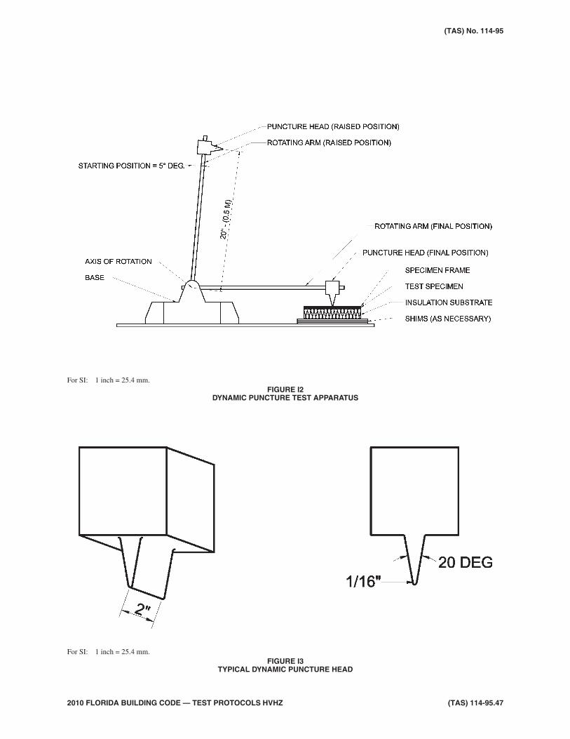
2010 FLORIDA BUILDING CODE — TEST PROTOCOLS HVHZ (TAS) 114-95.47
(TAS) No. 114-95
For SI: 1 inch = 25.4 mm.FIGURE I3
TYPICAL DYNAMIC PUNCTURE HEAD
For SI: 1 inch = 25.4 mm.FIGURE I2
DYNAMIC PUNCTURE TEST APPARATUS

(TAS) 114-95.48 2010 FLORIDA BUILDING CODE — TEST PROTOCOLS HVHZ
Scope:1.
1.1 Damage incurred by the effects of windover and internal pressure under a totallyadhered, partially adhered or mechani-cally attached Roof System Assemblygenerally results in one or more of the fol-lowing:
• Uplift of the cover (when totally ad-hered);
• Delamination within the roof insu-lation cover (when totally or par-tially adhered);
• Failure of adhesive between the in-sulation and the deck or between theinsulation and the vapor retarderand/or between the vapor retarderand the deck; and,
• Failure of the fastener/substrate,fastener/insulation or fastener/roofcover combination.
1.2 Thus the nature of the damage incurredwould suggest that an instrument de-signed to measure the stability of roof as-semblies be equipped to evaluate bondstrength indicated in the items above. The12 foot by 24 foot simulated uplift pres-sure test has been designed for this pur-pose.
1.3 The object of the test is to provide a realis-tic method of evaluating the uplift resis-tance of a completed roof constructionand its individual components when ap-plied within a completed assembly. Thetest procedure must contain the ability torealistically evaluate the actual size of theroof components which comprise a com-pleted roof system assembly.
1.4 The test method is applicable to any roofsystem assembly incorporating the deck,air/vapor retarders, insulation, roof cover,adhesives, sealants, mechanical fasteners,batten bars and proprietary fastening sys-tems.
1.5 The test method is designed to measurethe stability of the Roof System Assemblyon its supports and to evaluate the ulti-mate strength of the individual compo-nents in the completed Roof SystemAssembly under static conditions whichare intended to simulate the uplift loadsimposed by wind forces on the roof sys-tem. The roof specimen is sufficientlylarge so that the means of securing theperimeter of the sample to the pressurevessel have virtually no effect on the ulti-mate behavior of the assembly duringtesting.
1.6 The test procedure described in AppendixC does not adequately evaluate the perfor-mance of some newer roof constructions.With the increased use of extended fas-tener spacings in mechanically attachedsingle-ply cover construction and air/va-por retarders, the perimeter edge effect ofsmall or intermediate scale tests producesunreliable results. Therefore, a largersample size is needed to properly evaluateresistance to wind uplift forces.
Terminology–the following definitions applyto the test procedure outlined herein.
2.
2.1 Failure–Roof system assembly failure un-der this test standard could be one or moreof the following:
• withdrawal or breakage of fasteners;
• tearing, splitting or other breakageof the roof cover at the point(s) of at-tachment;
• impairment of the waterproofingfunction of the roof systems assem-bly (i.e. cracking of componentswithin the assembly);
• permanent deformation of the roofcover or fastener assembly, includ-ing stress plate, which may reducethe waterproofing function of theroof system assembly over time;and,
• delamination or separation of ad-hered areas.
2010 FLORIDA BUILDING CODE — TEST PROTOCOLS HVHZ (TAS) 114-95.49
TESTING APPLICATION STANDARD (TAS) 114-95APPENDIX J
TEST PROCEDURE FOR 12 FOOT BY 24 FOOT SIMULATED UPLIFT PRESSURERESISTANCE OF ROOF SYSTEM ASSEMBLIES
Apparatus:3.
3.1 The 12 foot by 24 foot uplift pressure ap-paratus is a steel pressure vessel arrangedto supply air pressure at pre-establishedpressure levels to the underside of the roofsystem assembly. This roof system as-sembly, when secured in place, forms andseals the top of the pressure vessel.
3.2 The pressure vessel measures 24 feet-7inch long by 12 feet-7 inch wide by 2 inchdeep (7.5 m by 3.8 m by 51 mm). It is fab-ricated from 8 inch (203 mm) deep steelchannel sections as the perimeter struc-ture with 6 inch (152 mm) deep steelbeams spaced 2 feet (0.6 m) o.c. runningparallel to the width. The bottom of thepressure vessel is sheathed with a 7 gauge(4.8 mm) thick steel plate spot welded tothe top of the steel beams and continu-ously welded to the inside perimeterchannels.
3.3 The air supply into the sealed vessel isprovided by an inlet manifold constructedwith 4 inch (102 mm) diameter PVC pipe.Four openings, equally spaced, penetratethe steel plate and serve as the air inlet onthe bottom of the pressure vessel. A 1/4
inch (6.4 mm) opening on the bottom ofthe vessel serves as the manometer con-nection. A foam gasket that lies betweenthe top channel of the pressure vessel andthe sample construction frame minimizesair leakage when the sample is clampedinto place.
3.4 Pressurized air is supplied to the inletmanifold by a turbo pressure blower hav-ing the capability of generating 600 cubicfeet per minute (17 m3/min). The air flowis regulated by a manually operated 4 inch(102 mm) diameter PVC butterfly valve.Pressure readings are obtained from a wa-ter filled manometer calibrated to read di-rectly in pounds per square feet.
Test Limitations and Precautions:4.
4.1 During the test, all testing agency repre-sentatives and other test observers shallwear ear and eye protection and hard hatsto prevent injury.
4.2 This test procedure may involve hazard-ous materials, operations and equipment.
This protocol does not purport to addressall of the safety problems associated withits use. It is the responsibility of the user toconsult and establish appropriate safetyand health practices and determine the ap-plicability of regulatory limitations priorto use.
Test Specimens:5.
5.1 The components for a proposed test panelare assembled to the desired specifica-tions and details (type and thickness of thedeck, application method and rate for theadhesive or fasteners, size and thicknessof insulation and type of cover) and thenleft to “cure” for the manufacturer’s spec-ified time period (maximum of 28 days).
5.2 When steel decking is used, it is securedto a 24 feet-7 inch by 12 feet-7 inch by 1/4
inch (7.5 m by 3.8 m by 6.4 mm) angleiron frame. This test specimen frame typi-cally includes a structural steel support lo-cated along the centerline and parallel tothe length. In addition, three intermediatestructural steel supports are located paral-lel to the width, 6 feet (1.8 m) o.c.. Thesteel deck is then applied parallel to thelength. It is welded to the perimeter angleiron with 1/2 inch (13 mm) diameter pud-dle welds 12 inch (305 mm) o.c. along theentire perimeter. In addition, it is fastenedat all supports [6 feet (1.8 m) spans for 22gage (0.75 mm) steel] 12 inch (305 mm)o.c. with approved fasteners. All deckside laps are fastened with approved fas-teners spaced at a maximum of 30 inch(762 mm) o.c. Other structural roof decksmay be used if requested by the programsponsor. Their application is according tothe manufacturer’s specifications and ap-proval requirements.
Note: The method of securing the steel deck tothe test frame may vary when a specifictest, as requested by an applicant, dictates.
5.3 When ready for testing, the test specimenframe, containing the test specimen, isplaced on the pressure vessel and clampedinto place using C-clamps and 2 inch by 3inch by 1/4 inch (51 mm by 76 mm by 6.4mm) steel angles placed around the per-imeter of the sample [smaller dimensionhorizontal and the 3 inch (76 mm) leg fac-ing down]. See Figures K1 and K2,herein. In addition, the test specimen
(TAS) 114-95.50 2010 FLORIDA BUILDING CODE — TEST PROTOCOLS HVHZ
(TAS) No. 114-95
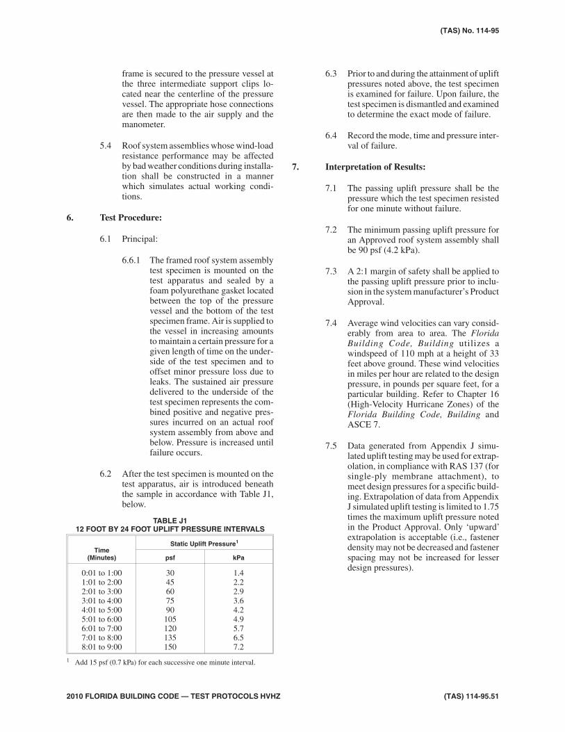
frame is secured to the pressure vessel atthe three intermediate support clips lo-cated near the centerline of the pressurevessel. The appropriate hose connectionsare then made to the air supply and themanometer.
5.4 Roof system assemblies whose wind-loadresistance performance may be affectedby bad weather conditions during installa-tion shall be constructed in a mannerwhich simulates actual working condi-tions.
Test Procedure:6.
6.1 Principal:
6.6.1 The framed roof system assemblytest specimen is mounted on thetest apparatus and sealed by afoam polyurethane gasket locatedbetween the top of the pressurevessel and the bottom of the testspecimen frame. Air is supplied tothe vessel in increasing amountsto maintain a certain pressure for agiven length of time on the under-side of the test specimen and tooffset minor pressure loss due toleaks. The sustained air pressuredelivered to the underside of thetest specimen represents the com-bined positive and negative pres-sures incurred on an actual roofsystem assembly from above andbelow. Pressure is increased untilfailure occurs.
6.2 After the test specimen is mounted on thetest apparatus, air is introduced beneaththe sample in accordance with Table J1,below.
6.3 Prior to and during the attainment of upliftpressures noted above, the test specimenis examined for failure. Upon failure, thetest specimen is dismantled and examinedto determine the exact mode of failure.
6.4 Record the mode, time and pressure inter-val of failure.
Interpretation of Results:7.
7.1 The passing uplift pressure shall be thepressure which the test specimen resistedfor one minute without failure.
7.2 The minimum passing uplift pressure foran Approved roof system assembly shallbe 90 psf (4.2 kPa).
7.3 A 2:1 margin of safety shall be applied tothe passing uplift pressure prior to inclu-sion in the system manufacturer’s ProductApproval.
7.4 Average wind velocities can vary consid-erably from area to area. The FloridaBuilding Code, Building utilizes awindspeed of 110 mph at a height of 33feet above ground. These wind velocitiesin miles per hour are related to the designpressure, in pounds per square feet, for aparticular building. Refer to Chapter 16(High-Velocity Hurricane Zones) of theFlorida Building Code, Building andASCE 7.
7.5 Data generated from Appendix J simu-lated uplift testing may be used for extrap-olation, in compliance with RAS 137 (forsingle-ply membrane attachment), tomeet design pressures for a specific build-ing. Extrapolation of data from AppendixJ simulated uplift testing is limited to 1.75times the maximum uplift pressure notedin the Product Approval. Only ‘upward’extrapolation is acceptable (i.e., fastenerdensity may not be decreased and fastenerspacing may not be increased for lesserdesign pressures).
2010 FLORIDA BUILDING CODE — TEST PROTOCOLS HVHZ (TAS) 114-95.51
(TAS) No. 114-95
TABLE J112 FOOT BY 24 FOOT UPLIFT PRESSURE INTERVALS
Time(Minutes)
Static Uplift Pressure1
psf kPa
0:01 to 1:001:01 to 2:002:01 to 3:003:01 to 4:004:01 to 5:005:01 to 6:006:01 to 7:007:01 to 8:008:01 to 9:00
3045607590105120135150
1.42.22.93.64.24.95.76.57.2
1 Add 15 psf (0.7 kPa) for each successive one minute interval.

(TAS) 114-95.52 2010 FLORIDA BUILDING CODE — TEST PROTOCOLS HVHZ
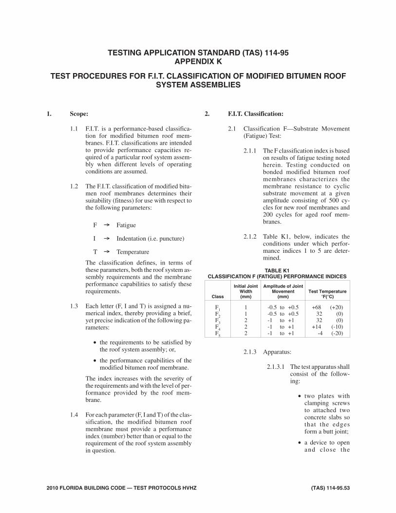
Scope:1.
1.1 F.I.T. is a performance-based classifica-tion for modified bitumen roof mem-branes. F.I.T. classifications are intendedto provide performance capacities re-quired of a particular roof system assem-bly when different levels of operatingconditions are assumed.
1.2 The F.I.T. classification of modified bitu-men roof membranes determines theirsuitability (fitness) for use with respect tothe following parameters:
F Fatigue
I Indentation (i.e. puncture)
T Temperature
The classification defines, in terms ofthese parameters, both the roof system as-sembly requirements and the membraneperformance capabilities to satisfy theserequirements.
1.3 Each letter (F, I and T) is assigned a nu-merical index, thereby providing a brief,yet precise indication of the following pa-rameters:
• the requirements to be satisfied bythe roof system assembly; or,
• the performance capabilities of themodified bitumen roof membrane.
The index increases with the severity ofthe requirements and with the level of per-formance provided by the roof mem-brane.
1.4 For each parameter (F, I and T) of the clas-sification, the modified bitumen roofmembrane must provide a performanceindex (number) better than or equal to therequirement of the roof system assemblyin question.
F.I.T. Classification:2.
2.1 Classification F—Substrate Movement(Fatigue) Test:
2.1.1 The F classification index is basedon results of fatigue testing notedherein. Testing conducted onbonded modified bitumen roofmembranes characterizes themembrane resistance to cyclicsubstrate movement at a givenamplitude consisting of 500 cy-cles for new roof membranes and200 cycles for aged roof mem-branes.
2.1.2 Table K1, below, indicates theconditions under which perfor-mance indices 1 to 5 are deter-mined.
2.1.3 Apparatus:
2.1.3.1 The test apparatus shallconsist of the follow-ing:
• two plates withclamping screwsto attached twoconcrete slabs sothat the edgesform a butt joint;
• a device to openand close the
2010 FLORIDA BUILDING CODE — TEST PROTOCOLS HVHZ (TAS) 114-95.53
TESTING APPLICATION STANDARD (TAS) 114-95APPENDIX K
TEST PROCEDURES FOR F.I.T. CLASSIFICATION OF MODIFIED BITUMEN ROOFSYSTEM ASSEMBLIES
TABLE K1CLASSIFICATION F (FATIGUE) PERFORMANCE INDICES
Class
Initial JointWidth(mm)
Amplitude of JointMovement
(mm)Test Temperature
F(°C)
F1F2F3F4F5
11222
-0.5 to +0.5-0.5 to +0.5-1 to +1-1 to +1-1 to +1
+68 (+20)32 (0)32 (0)
+14 (-10)-4 (-20)
→
→
→
joint at a rate of 5/8
inch per hour (16mm/hr) and at ac o n t r o l l e damplitude;
• a climactic cham-ber so the testspecimen can bekept at a con-trolled tempera-ture.
2.1.4 Test specimens:
2.2.4.1 Test specimen shallconsist of 12 inch by 2inch (300 mm by 50mm) strips of mem-brane placed on theconcrete slabs with thecenter of the 12 inch di-mension centered at thebutt joint, which is setat the joint width forthe various F classifi-cations noted in TableK1.
2.2.4.2 A total of six test speci-men strips shall betested; three unagedand three which havebeen conditioned at176°F (80°C) for 28days.
2.2.4.3 Specimens shall befully adhered to theconcrete slabs usingthe method noted in themembrane manufac-turer’s published liter-ature.
2.1.5 Procedure:
2.1.5.1 From the initial posi-tion, the joint is openedand closed alternatelyunder the followingconditions:
• the amplitude ofmovement is +0.5 mm or + 1mm, dependingon the perfor-mance index be-
ing tested (see Ta-ble K1);
• the test tempera-ture is +68 °F,+32°F, +14°F or-4°F dependingon the perfor-mance index be-ing tested; and,
• the number of cy-cles is 500 forunaged and 200for aged speci-mens.
2.1.6 Observations:
2.1.6.1 The test is terminatedat the end of 200 cyclesfor aged and 500 cyclesfor unaged specimensat which time:
• the samples arechecked forwatert ightnessunder a 5centimeters highwater column orby equivalentmethod; and,
• any loss of bondis observed andreported.
2.1.6.2 Failure criteria shall becomplete loss of adhe-sion or delamination ofthe specimens.
2.2 Classification I–Static and DynamicPuncture Test:
2.2.1 The I classification index is basedon results of static and dynamicpuncture resistance testing notedin Appendix I of TAS 114. Testingconducted on bonded roof mem-branes characterizes the mem-brane resistance to static anddynamic impact loading.
2.2.2 Tables K2 through K4, below,indicate the conditions underwhich performance indices 1 to5 are determined.
(TAS) 114-95.54 2010 FLORIDA BUILDING CODE — TEST PROTOCOLS HVHZ
(TAS) No. 114-95

2.2.3 Apparatus, Procedure and Obser-vations shall be in compliancewith Appendix I of TAS 114.
2.3 Classification T–Temperature Stability:
2.3.1 The T classification index is basedon results of slippage resistancetesting under the effects of tem-perature noted herein. Testingconducted on bonded modifiedbitumen roof membranes charac-terizes the membrane resistance toslippage under the effects of tem-perature.
2.3.2 Table K5, below, indicates the con-ditions under which performanceindices 1 to 4 are determined.
2.3.3 Apparatus
2.3.3.1 The test apparatus shallconsist of the follow-ing:
• A heat chambercontrolled towithin +5°F, withan operating rangefrom +120°F to notless than +250°F;
• A frame to whichthe test specimendescribed belowis attached in asloping positionof 45 degrees.The frame mustal low the testspecimen to bekept in a horizon-tal position dur-ing the t imenecessary for theselected test tem-perature to stabi-lize;
• A series of cleandegreased steelplates, 0.08 inchthick by 73/4 inchby 153/4 inch (2mm thick by 200mm by 400 mm),prepared accord-ing to Figure K1,below. Each platehas 2 screws andnuts of appropri-ate diameter forthe holes drilledin the edges of theplate;
• A metal rule notless than 7 3/ 4
inches (200 mm)long;
• A device to mea-sure length towithin 0.1 mm;and
• Thin aluminumplates 2 inch by 6inch (50 mm by150 mm) and a 2-component adhe-sive.
2010 FLORIDA BUILDING CODE — TEST PROTOCOLS HVHZ (TAS) 114-95.55
(TAS) No. 114-95
TABLE K5CLASSIFICATION T (TEMPERATURE STABILITY)
PERFORMANCE INDICES
ClassSlippage Amplitude
(mm)Test Temperature
F ( C)
T1T2T3T4
> 2< 2< 2< 2
140 (60)140 (60)176 (80)194 (90)
TABLE K2SUBCLASSIFICATION L (STATIC PUNCTURE)
PERFORMANCE INDICES
Subclass Static Load lb (kg)
L1L2L3L4
<15 (7 )>15 (7)>33 (15)>55 (25)
TABLE K3SUBCLASSIFICATION D (DYNAMIC PUNCTURE)
PERFORMANCE INDICES
SubclassImpact Energy
ft-pdl (J)
D1D2
D3
<240 (10)>240 (10)<480 (20)>480 (20)
TABLE K4CLASSIFICATION I (INDENTATION)
PERFORMANCE INDICES
Class Subclass L Subclass D
I1I2I3I4I5
L1L2L3L4L5
D2D2D2D2D3

2.3.4 Test Specimens:
2.3.4.1 Test specimen shallconsist of 12 inch by 6inch (300 mm by 150mm) membrane sam-ples adhered or torchedto the steel plate (do notuse primer) in compli-ance with the mem-brane manufacturer’spublished instructions.
2.3.4.2 Put the screws and nutsin place.
2.3.4.3 Glue the aluminumplate to the membranesurface such that it ispossible, before and af-ter exposure to heat, todraw a line on the platewith a scribe using ametal rule which isplaced against thescrews.
2.3.4.4 Three test specimensshall be constructed.
2.3.5 Procedure:
2.3.5.1 Condition the test spec-imens at ambient con-di t ions in thehorizontal position for24 hours.
2.3.5.2 Draw a line to show theinitial position.
2.3.5.3 Set the heat chamber tothe required test tem-perature.
2.3.5.4 Place the test specimenin horizontal positionin the heat chamber,and allow it to remainthere for one hour.
2.3.5.5 Put the test specimen inthe test position, slop-ing at an angle of 45degrees, in less than 5seconds. Keep it in thisposition at the test tem-perature for 2 hours.
2.3.5.6 Remove the test speci-men from the chamberand allow it to cool atambient conditions inthe horizontal position.
2.3.5.7 Draw a line to indicatethe final position.
2.3.6 Observations:
2.3.6.1 Measure the differencebetween the two linesalong each edge.
2.3.6.2 Slippage of the mem-brane is expressed asthe average of the threetest specimens.
Classification of Membrane Use:3.
3.1 The ascending order of the indices as-signed to each of the F.I.T. letters corre-
(TAS) 114-95.56 2010 FLORIDA BUILDING CODE — TEST PROTOCOLS HVHZ
(TAS) No. 114-95
For SI: 1.02 mm = 0.040 inch
FIGURE K1SCHEMATIC OF STEEL PLATE FOR TEMPERATURE
STABILITY TEST

sponds to increasingly severe conditionsof use.
3.2 Table K6, below, summarizes the classifi-cation of the roof system assembly withrespect to the three parameters F.I.T. Itprovides the total classification of the re-quired modified bitumen membrane roofsystem assembly.
3.2.1 Based on the premise of increas-ing performance capacity, a modi-fied bi tumen membrane
classification greater than thatrequired of the roof system assem-bly would be a wise precaution.
2010 FLORIDA BUILDING CODE — TEST PROTOCOLS HVHZ (TAS) 114-95.57
(TAS) No. 114-95
TABLE K6
MembraneSubstrate Slope
Roof Use and Type of Protection
Non-Functional
Functional Access Roof EquipmentMaintenance
WalkwayPedestrian Vehicles Pedestrian Gardens
Factory AppliedSurfacing Slabs - Pavers
Protection Slabson Spacers
Direct DrainageLayer
Factory AppliedSurfacing
ThermalInsulation
0 F4I2T2(1) (2) F5I4T3 F3I5T1 F4I4T2
Low(<4":12")
F4I2T2(1) (2) F4I4T2 F4I4T2 F5I4T3 F3I5T2 F4I4T2
Pitched(4":12")
F4I2T2(3) F4I2T2
(3)
Concrete
0 F4I2T2 F5I4T3 F3I5T1 F4I4T2
Low(<4":12")
F4I2T2 F4I4T2 F4I4T2 F5I4T3 F3I5T2 F4I4T2
Pitched(4":12")
F4I2T2 F4I4T2
Concrete &Protected
Membrane
0 F3I3T2 F3I5T1
Low(<4":12")
F3I3T2 F3I3T2 F3I5T2
CellularConcrete
Low(<4":12")
F4I2T2 F4I4T2
Pitched(4":12")
F4I2T2 F4I4T2
Wood andDerived Panels
Low(<4":12")
F4I2T2 F4I4T2(3)
Pitched(4":12")
F4I2T2(3) F4I4T2
(3)
ExistingMembrane
0 F4I2T2 F5I4T3 F3I5T1 F4I4T2
Low(<4":12")
F4I2T2 F4I4T2 F4I4T2 F5I4T3 F3I5T2 F4I4T2
Pitched(4":12")
F4I2T2(3) F4I4T2
(3)
1 Index I becomes I3 for mineral wool over concrete and cellular concrete.2 Index I becomes I3 on R > 2m2 °C/W mineral wool.3 Index T becomes T3 if R > 2m2 °C/W.

(TAS) 114-95.58 2010 FLORIDA BUILDING CODE — TEST PROTOCOLS HVHZ


![WD1 Wind Design Standard...[ 4 ] ANSI/SPRI Wind Design Standard Practice for Roofing Assemblies Approved September 3, 2008 FM 4450, FM 4470, ANSI/FM 4474, UL 580, UL …](https://img.pdfslide.us/doc/110x75/60fd468711f012519d79924d/wd1-wind-design-standard-4-ansispri-wind-design-standard-practice-for-roofing.jpg)