Embed Size (px)
Citation preview
Testing and Control Technology
Hydraulic Flushing Test Rig.
Overview
On completion of the hydraulic pipe work installation, and prior to despatch of the wing there is a requirement to flush all pipe work standard of NAS 1648 Class 7 or better, pressure test and proof pressure test the Single Aisle Wing hydraulic system pipe work prior to fitting the hydraulic Components.
Operation
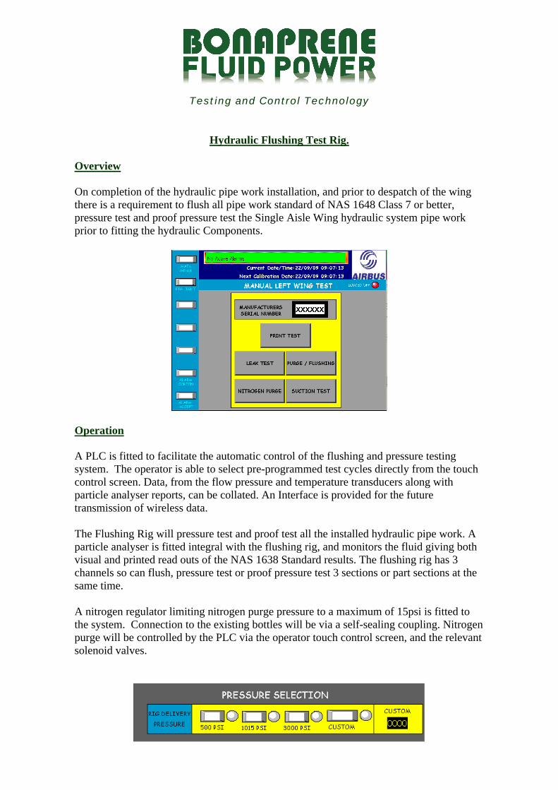
A PLC is fitted to facilitate the automatic control of the flushing and pressure testing system. The operator is able to select pre-programmed test cycles directly from the touch control screen. Data, from the flow pressure and temperature transducers along with particle analyser reports, can be collated. An Interface is provided for the future transmission of wireless data.
The Flushing Rig will pressure test and proof test all the installed hydraulic pipe work. A particle analyser is fitted integral with the flushing rig, and monitors the fluid giving both visual and printed read outs of the NAS 1638 Standard results. The flushing rig has 3 channels so can flush, pressure test or proof pressure test 3 sections or part sections at the same time.
A nitrogen regulator limiting nitrogen purge pressure to a maximum of 15psi is fitted to the system. Connection to the existing bottles will be via a self-sealing coupling. Nitrogen purge will be controlled by the PLC via the operator touch control screen, and the relevant solenoid valves.
CLYWEDOG ROAD SOUTH TELEPHONE: +44 (0) 1978 667720WREXHAM INDUSTRIAL ESTATE FAX: +44 (0) 1978 661190WREXHAM E-MAIL: [email protected] 9XS. UK www.bonaprenefluidpower.co.uk
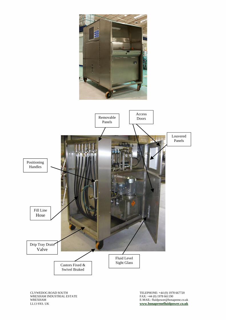
Removable Panels
Access Doors
Louvered Panels
Fluid Level Sight Glass
Castors Fixed & Swivel Braked
Fill LineHose
Drip Tray DrainValve
Positioning Handles