Embed Size (px)
Citation preview

HYDRAULIC CONTROL
SYSTEM Intermediate

PARCOL
- 2 -
HYDRAULIC CONTROL SYSTEM INTERMEDIATE
HYDRAULIC POWER UNIT
The hydraulic power unit (HPU) is provided with a steel oil tank suitable for outdoor service able to collect the full
volume of oil present in the circuit. The tank is equipped with inspection door, breather with filter, 2 level switches,
1 temperature switch, 1 visual level indicator.
Two main motor-pump groups P1 and P2, each one fitted with an electric motor, are provided on the tank; the
fixed displacement pump is able to deliver the required flow rate at a pressure of 200 bar.
A filtering/conditioning group composed by fixed displacement pump P3, filter with clogging detector (DPS3) and
exchanger (R) with fan piloted by internal thermostat is provided on board.
Functions of the main pumps are :
n° 1 active pump, to maintain all control valves in closed/open position or under continuous control.
n° 1 stand-by pump to be activated on alarm signal from low pressure switch mounted on pump common
delivery manifold
The pump flow rate is enough to ensure the maximum stroke time required in control mode for each valve without involving the accumulator intervention.
Four pressure switches are installed in the common delivery manifold of the motor-pump groups, as follows:
PS1 supplies the “low oil pressure signal"
PS2 supplies the “minimum oil pressure signal” (i.e. plant out of commission).
PS3 stops the active pump
PS4 starts the active pump
One accumulator A1, constantly inserted on the delivery manifold, is installed on the hydraulic power unit to grant
trouble-free change-over from a motor/pump group to the other one.
The overflow valve VS3 controls the oil pressure in the primary circuit.
Two sealed maximum pressure safety valves VS1 and VS2 are mounted on pump deliveries.
A double filter F provided with electric clogging detectors DPS1-DPS2 is installed at power unit outlet.
The hydraulic power unit is provided with two terminal boxes: the first one is intended for instrument cables, the
second one for the electric motor control cabinet (M.C.C.).
Options:
Inox oil tank
Heating system
Hand pump
Fire resistance oil version
First filling oil
Charging and testing unit for accumulators

PARCOL
- 3 -
HYDRAULIC CONTROL SYSTEM INTERMEDIATE
HYDRAULIC POWER UNIT
HYDRAULIC DIAGRAM

PARCOL HYDRAULIC CONTROL SYSTEM INTERMEDIATE
- 4 -
HYDRAULIC CONTROL PANEL (HCP)
The control panel for control valves consists of:
N° 2 SV proportional valves (steam and desuper. control valves), supplied with built-in electronic circuits ON-OFF, two-position solenoid valves (EV), to perform emergency actions (fast opening < 1 sec) accumulator The HCP houses also analogue positioning cards (steam valves and desuperheating valves) for stroke control in closed loop system.
The response time of ON-OFF valves may be separately adjusted by suitable throttling devices.
The hydraulic circuit should be provided with gate valves to allow maintenance actions.
Complete cycles are allowed, when pumps are still, within 15 minutes from pump stop, because of leakages.
Options:
Hand pump
ON-OFF valves for fast closing < 3 sec
HYDRAULIC DIAGRAM

PARCOL HYDRAULIC CONTROL SYSTEM INTERMEDIATE
- 5 -
HYDRAULIC CONTROL PANEL
- 6 -
PARCOL HYDRAULIC CONTROL SYSTEM INTERMEDIATE
ELECTRIC CONTROL CABINET
The electric control cabinet is supplied with a redundant feeder/transformer for auxiliary circuits (240 Vac 24 Vdc), warning lights, lamps, contactors and any other necessary component to grant the efficiency of the whole hydraulic equipment.
The cabinet, fitted with a fan (extractor) complete with replaceable cartridge, includes an auxiliary electrical socket .
Manufactured according to the industrial standards, with minimum protection degree IP42, houses the control system for emergency solenoid valves and 1 PLC to manage the Hydraulic Power Unit, the Control Panel and the interchange signals with control room.
The cabinet houses also analogue positioning cards (steam valves and desuperheating valves) for stroke control in closed loop system.
Auxiliary circuits are separately protected, even when redundant (pumps control, PLC power supply and proportional valves). Cable entry from bottom.
Max cable run from cabinet to control panel approx. 200 m.
Max resistance of proportional valves supply cable 2 W.
Approximate sizes 1200 x 2000 (+ 100) x 600 mm.
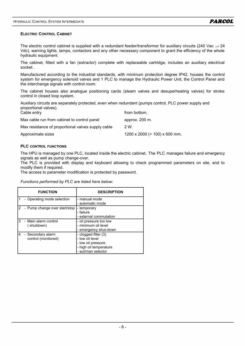
PLC CONTROL FUNCTIONS
The HPU is managed by one PLC, located inside the electric cabinet. The PLC manages failure and emergency signals as well as pump change-over. The PLC is provided with display and keyboard allowing to check programmed parameters on site, and to modify them if required. The access to parameter modification is protected by password. Functions performed by PLC are listed here below:
FUNCTION DESCRIPTION
1 - Operating mode selection - manual mode - automatic mode
2 - Pump change over start/stop - temporary - failure - external commutation
3 - Main alarm control ( shutdown)
- oil pressure too low - minimum oil level - emergency shut-down
4 - Secondary alarm control (monitored)
- clogged filter (3) - low oil level - low oil pressure - high oil temperature - aut/man selector

- 7 -
PARCOL HYDRAULIC CONTROL SYSTEM INTERMEDIATE
1 OPERATING MODE SELECTION
The operating mode may be selected by a suitable selector located on control cabinet front. Manual Mode
Necessary in order to allow the plant start-up. The PLC does not affect the pump selection, but allows to select the pump to be started (by using the pump change-over push-buttons). By this mode all monitoring functions towards warning lights and Control Room are implemented.
2 PUMPS CONTROL
Start-Stop Timed change-over Change-over due to failure External commutation
3 MAIN ALARM CONTROL Minimum oil level On minimum oil level signal, the pumps are stopped. Minimum oil pressure Pumps are not stopped on minimum oil pressure. Control cabinet emergency shut-down
4 SECONDARY ALARM CONTROL
Clogged oil filter Low oil level Low oil pressure High oil temperature AUT/MAN selector on MAN position
Options:
Control axis digital cards expansion
Cabinet conditioning equipment for indoor installation

PARCOL HYDRAULIC CONTROL SYSTEM INTERMEDIATE
ACA 0595 - 09/13 - HYDRAULIC CONTROL SYSTEM
PARCOL S.p.A. Via Isonzo, 2 - 20010 CANEGRATE (MI) - ITALY
Telephone: +39 0331 413.111 - Fax: +39 0331 404.215 E-mail: [email protected] - http://www.parcol.com
CONTROL HYDRAULIC ACTUATORS
Double acting cylinders built in compliance with ISO 6020-2 and DIN 24554. On board are installed the inductive limit switches (n° 1 open posit. + n° 1 close posit. – SPDT contacts) and position transducer (4 ÷ 20 mA)
ON-OFF HYDRAULIC ACTUATORS
Double acting cylinders built in compliance with ISO 6020-2 and DIN 24554. On board are installed the mechanical limit switches (n° 1 open posit. + n° 1 close posit. – SPDT contacts)
Options:
DPDT contacts (limit switches)
n° 4 limit switches (n°2 open posit. + n° 2 close posit.)
HYDRAULIC CYLINDER FOR CONTROL VALVES
HYDRAULIC CONTROL SYSTEM INTERCONNECTIONS DIAGRAM