Embed Size (px)
DESCRIPTION
testim more testim
Citation preview
EESTC
PROCESS DIAGRAM AND ELEMENTS ALLOCATION
SCADA. EDIBON Computer Control System:Computer Control + Data Acquisition + Data Management
Sensors
Teaching unit
ControlInterface
Box
1
2
3
45
6“n”
Studentpost
Dat
aac
quis
ition
boar
dCableto
computerSoftware for:-Computer Control-Data Acquisition-Data Management
Cables toControl
Interface Box
OPEN CONTROL+
MULTICONTROL+
REAL TIME CONTROL
Computer Controlled Thermal Solar Energy Unit
VP-1: Main purge valve-primary circuit.
VR-1: Regulation valve-primary circuit.
V2: Valve in free circulation circuit-primary circuit.
V3: Second purge valve-primary circuit.
V4: Valve to fill the water closed circuit-primary circuit.
V5: Valve to Open/Close the cold water inlet-secondary circuit.
V6: Valve to Open/Close the hot water outlet-secondarycircuit.
V7: Third purge palve.
C1 and SC1: Flowmeter and flow sensor in primary circuit.
C2 and SC2: Flowmeter and flow sensor in secondary circuit.
ST1 to ST10: Temperature sensors.
Software for:4
- Data Acquisition- Data Management
- Computer ControlData
AcquisitionBoard
32
Control Interface Box
SCADA. EDIBON Computer Control System
TeachingTechnique
used
Always included in the supply:
Computer(not included in the supply)
Cables and Accessories Manuals
5
6
www.edibon.comProducts
Products rangeUnits
5.-Energy
Technical Teaching Equipment
Worlddidac Quality Charter Certificate
WorlddidacMember
ISO 9001:2000Certificate of Approval
European Union Certificate Certificates ISO 14001: 2004 andECO-Management and Audit Scheme
(environmental management) Worlddidac MemberPage 1
5 actuators and 12 sensors controlled from any computer,and working simultaneously
1 Unit: EESTC. Thermal Solar Energy Unit
SPECIFICATIONS
1
2
3
Items supplied as standard
4
5
6
www.edibon.com
References 1 to 6: EESTC + EESTC/CIB + DAB + EESTC/CCSOF + Cables and Accessories + Manuals are included in the minimum supply, enabling a normal operation.*
EESTC/CIB
DAB
EESTC/CCSOF
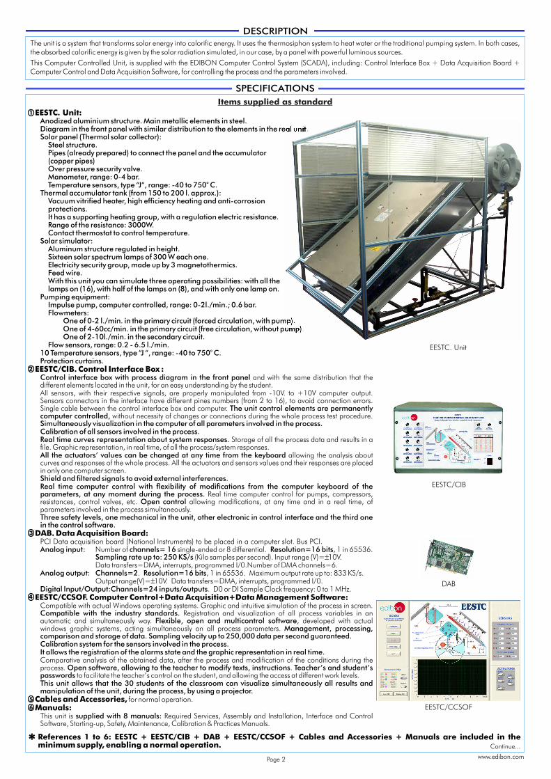
EESTC. Unit:Anodized aluminium structure. Main metallic elements in steel. Diagram in the front panel with similar distribution to the elements in the real unit.Solar panel (Thermal solar collector):
Steel structure.Pipes (already prepared) to connect the panel and the accumulator (copper pipes)Over pressure security valve.Manometer, range: 0-4 bar.
oTemperature sensors, type “J“, range: -40 to 750 C.
Thermal accumulator tank (from 150 to 200 l. approx.):Vacuum vitrified heater, high efficiency heating and anti-corrosionprotections.It has a supporting heating group, with a regulation electric resistance.Range of the resistance: 3000W.Contact thermostat to control temperature.
Solar simulator:Aluminum structure regulated in height.Sixteen solar spectrum lamps of 300 W each one.Electricity security group, made up by 3 magnetothermics.Feed wire.With this unit you can simulate three operating possibilities: with all the lamps on (16), with half of the lamps on (8), and with only one lamp on.
Pumping equipment:Impulse pump, computer controlled, range: 0-2l./min.; 0.6 bar.Flowmeters:
One of 0-2 l./min. in the primary circuit (forced circulation, with pump).One of 4-60cc/min. in the primary circuit (free circulation, without pump).One of 2-10l./min. in the secondary circuit.
Flow sensors, range: 0.2 - 6.5 l./min.o
10 Temperature sensors, type “J “, range: -40 to 750 C.Protection curtains.
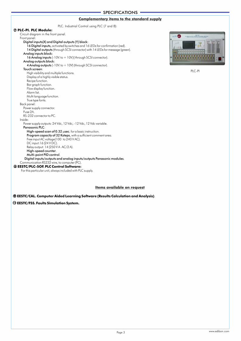
EESTC/CIB. Control Interface Box :Control interface box with process diagram in the front panel and with the same distribution that the different elements located in the unit, for an easy understanding by the student.All sensors, with their respective signals, are properly manipulated from -10V. to +10V computer output. Sensors connectors in the interface have different pines numbers (from 2 to 16), to avoid connection errors. Single cable between the control interface box and computer. The unit control elements are permanently computer controlled, without necessity of changes or connections during the whole process test procedure. Simultaneously visualization in the computer of all parameters involved in the process.Calibration of all sensors involved in the process.Real time curves representation about system responses. Storage of all the process data and results in a file. Graphic representation, in real time, of all the process/system responses.All the actuators’ values can be changed at any time from the keyboard allowing the analysis about curves and responses of the whole process. All the actuators and sensors values and their responses are placed in only one computer screen.Shield and filtered signals to avoid external interferences.Real time computer control with flexibility of modifications from the computer keyboard of the parameters, at any moment during the process. Real time computer control for pumps, compressors, resistances, control valves, etc. Open control allowing modifications, at any time and in a real time, of parameters involved in the process simultaneously.Three safety levels, one mechanical in the unit, other electronic in control interface and the third one in the control software.
DAB. Data Acquisition Board:PCI Data acquisition board (National Instruments) to be placed in a computer slot. Bus PCI.Analog input: Number of channels= 16 single-ended or 8 differential. Resolution=16 bits, 1 in 65536.
Sampling rate up to: 250 KS/s (Kilo samples per second). Input range (V)= 10V.Data transfers=DMA, interrupts, programmed I/0.Number of DMA channels=6.
Analog output: Channels=2. Resolution=16 bits, 1 in 65536. Maximum output rate up to: 833 KS/s.Output range(V)= 10V. Data transfers=DMA, interrupts, programmed I/0.
Digital Input/Output:Channels=24 inputs/outputs. D0 or DI Sample Clock frequency: 0 to 1 MHz.EESTC/CCSOF. Computer Control+Data Acquisition+Data Management Software:
Compatible with actual Windows operating systems. Graphic and intuitive simulation of the process in screen. Compatible with the industry standards. Registration and visualization of all process variables in an automatic and simultaneously way. Flexible, open and multicontrol software, developed with actual windows graphic systems, acting simultaneously on all process parameters. Management, processing,comparison and storage of data. Sampling velocity up to 250,000 data per second guaranteed.Calibration system for the sensors involved in the process.It allows the registration of the alarms state and the graphic representation in real time. Comparative analysis of the obtained data, after the process and modification of the conditions during the process. Open software, allowing to the teacher to modify texts, instructions. Teacher’s and student’spasswords to facilitate the teacher’s control on the student, and allowing the access at different work levels.This unit allows that the 30 students of the classroom can visualize simultaneously all results and manipulation of the unit, during the process, by using a projector.
Cables and Accessories, for normal operation.Manuals:
This unit is supplied with 8 manuals: Required Services, Assembly and Installation, Interface and Control Software, Starting-up, Safety, Maintenance, Calibration & Practices Manuals.
DESCRIPTIONThe unit is a system that transforms solar energy into calorific energy. It uses the thermosiphon system to heat water or the traditional pumping system. In both cases, the absorbed calorific energy is given by the solar radiation simulated, in our case, by a panel with powerful luminous sources.This Computer Controlled Unit, is supplied with the EDIBON Computer Control System (SCADA), including: Control Interface Box + Data Acquisition Board + Computer Control and Data Acquisition Software, for controlling the process and the parameters involved.
EESTC. Unit
Page 2
Continue...
±
±
EESTC/CAL. Computer Aided Learning Software (Results Calculation and Analysis).
EESTC/FSS. Faults Simulation System.
SPECIFICATIONS
7
Complementary items to the standard supply
Items available on request
PLC-PI
8
99
10
PLC. Industrial Control using PLC (7 and 8): PLC-PI. PLC Module:
EESTC/PLC-SOF. PLC Control Software:For this particular unit, always included with PLC supply.
Circuit diagram in the front panel.Front panel:
Digital inputs(X) and Digital outputs (Y) block: 16 Digital inputs, activated by switches and 16 LEDs for confirmation (red). 14 Digital outputs (through SCSI connector) with 14 LEDs for message (green).
Analog inputs block: 16 Analog inputs (-10V. to + 10V.)( through SCSI connector).
Analog outputs block: 4 Analog outputs (-10V. to + 10V) (through SCSI connector).
Touch screen:High visibility and multiple functions.Display of a highly visible status.
Recipe function.Bar graph function. Flow display function. Alarm list. Multi language function. True type fonts.
Back panel: Power supply connector.Fuse 2A. RS-232 connector to PC.
Inside:Power supply outputs: 24 Vdc, 12 Vdc, -12 Vdc, 12 Vdc variable.Panasonic PLC:
High-speed scan of 0.32 msec. for a basic instruction. Program capacity of 32 Ksteps, with a sufficient comment area. Free input AC voltage(100 to 240 V AC).DC input:16 (24 V DC).Relay output: 14 (250 V A AC/2 A). High-speed counter.Multi-point PID control.
Digital inputs/outputs and analog inputs/outputs Panasonic modules.Communication RS232 wire, to computer (PC).
www.edibon.comPage 3
EDIBON Computer Control System
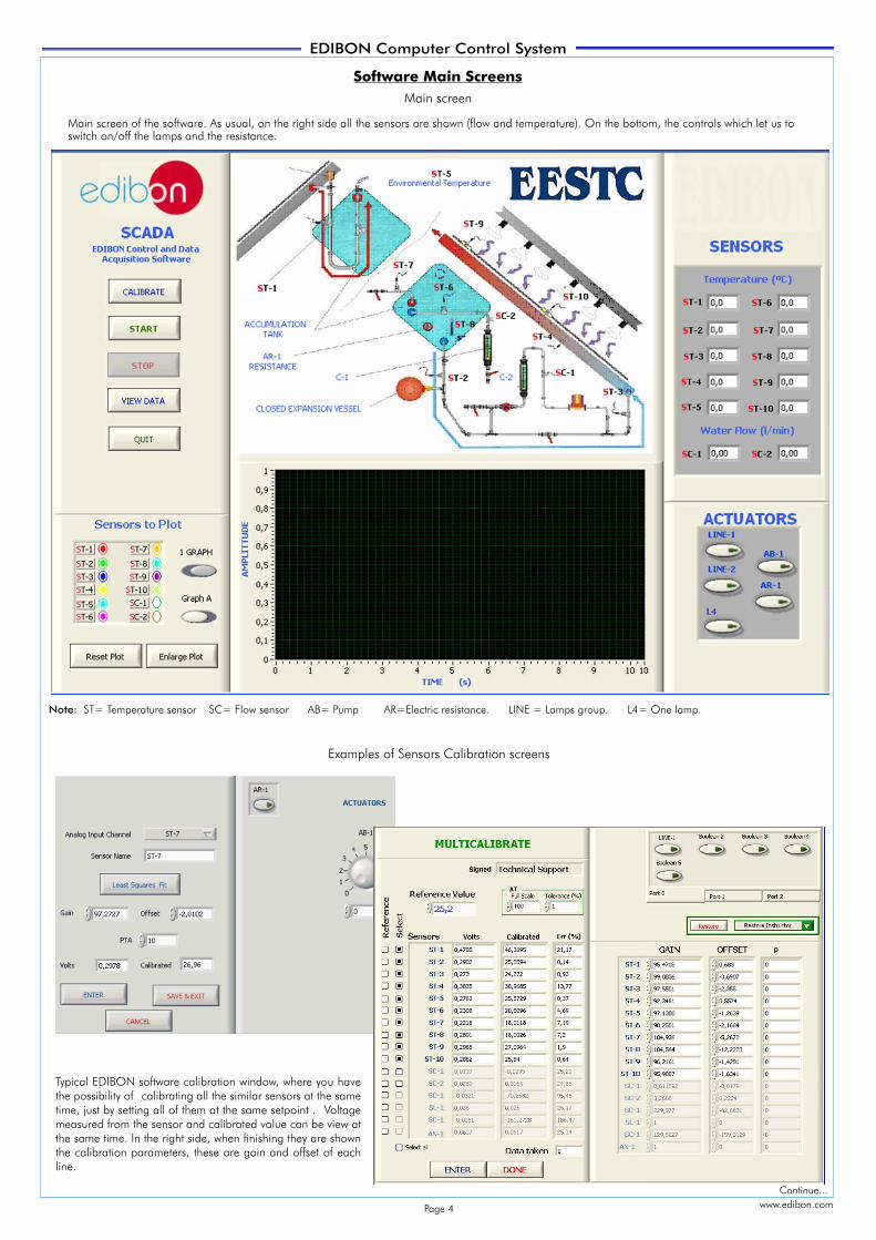
Software Main Screens
Main screen
Examples of Sensors Calibration screens
Note: ST= Temperature sensor SC= Flow sensor AB= Pump AR=Electric resistance. LINE = Lamps group. L4= One lamp.
www.edibon.com
Main screen of the software. As usual, on the right side all the sensors are shown (flow and temperature). On the bottom, the controls which let us to switch on/off the lamps and the resistance.
Typical EDIBON software calibration window, where you have the possibility of calibrating all the similar sensors at the same time, just by setting all of them at the same setpoint . Voltagemeasured from the sensor and calibrated value can be view at the same time. In the right side, when finishing they are shown the calibration parameters, these are gain and offset of each line.
Continue...
Page 4
EDIBON Computer Control System
www.edibon.com
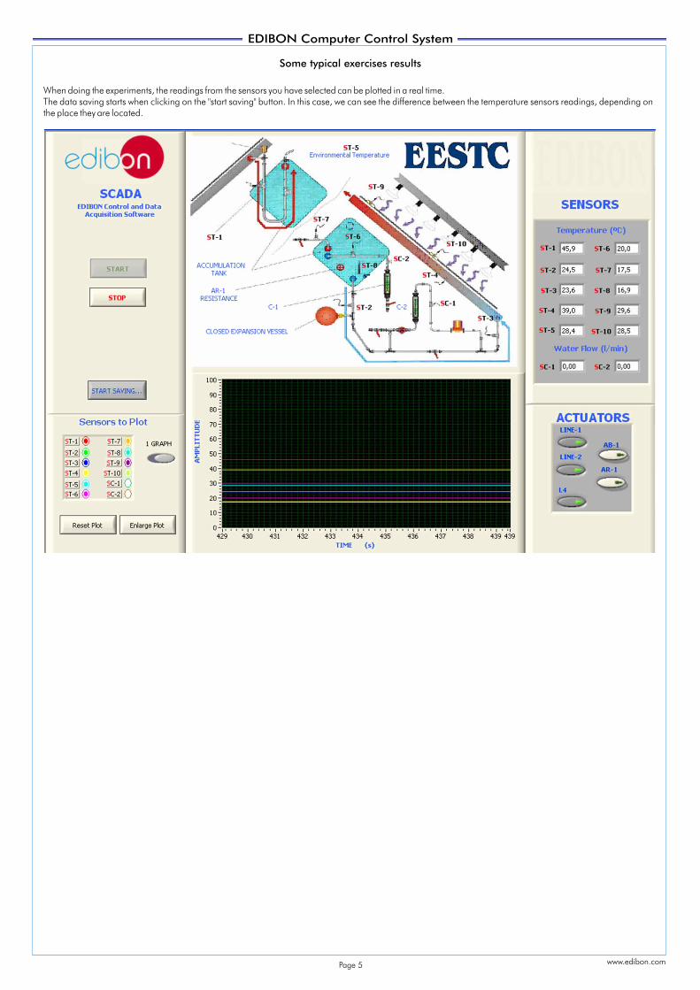
When doing the experiments, the readings from the sensors you have selected can be plotted in a real time. The data saving starts when clicking on the "start saving" button. In this case, we can see the difference between the temperature sensors readings, depending on the place they are located.
Some typical exercises results
Page 5
Minimum configuration for normal operation includes: PLC. Industrial Control using PLC (7 and 8):
Unit: EESTC. Thermal Solar Energy Unit. PCL-PI.PLC Module.
EESTC/CIB. Control Interface Box. EESTC/PLC-SOF. PLC Control Software.
DAB. Data Acquisition Board. EESTC/CAL. Computer Aided Learning Software (Results Calculation and Analysis). (Available on request).EESTC/CCSOF. Computer Control + Data Acquisition + Data
Management Software. EESTC/FSS. Faults Simulation System. (Available on request).
Cables and Accessories, for normal operation. Expansions
Manuals. Mini ESN. Multipost EDIBON Mini Scada-Net System.
ESN. Multipost EDIBON Scada-Net System.
* IMPORTANT: Under EESTC we always supply all the elements for immediate running as 1, 2, 3, 4, 5 and 6.
ORDER INFORMATION
1
6
2
3
4
5
7
11
12
10
9
8
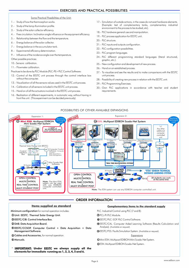
Some Practical Possibilities of the Unit:
1 .- Study of how the thermosiphon works. 17.- Simulation of outside actions, in the cases do not exist hardware elements.(Example: test of complementary tanks, complementary industrial 2 .- Study of the lamp illumination profile.environment to the process to be studied, etc).
3 .- Study of the solar collector efficiency.18.- PLC hardware general use and manipulation.
4 .- Free circulation: Inclination angle influence on the equipment efficiency.19.- PLC process application for EESTC unit.
5 .- Relationship between the flow and the temperature. 20.- PLC structure.
6 .- Energy balance of the solar collector.21.- PLC inputs and outputs configuration.
7 .- Energy balance in the accumulator tank.22.- PLC configuration possibilities.
8 .- Experimental efficiency determination.23.- PLC program languages.
9 .- Influence of the incidence angle over the temperature.24.- PLC different programming standard languages (literal structured,
Other possible practices: graphic, etc.).10.- Sensors calibration. 25.- New configuration and development of new process.11.- Flowmeter calibration. 26.- Hand on an established process.Practices to be done by PLC Module (PLC-PI)+PLC Control Software: 27.- To visualize and see the results and to make comparisons with the EESTC
unit process.12.- Control of the EESTC unit process through the control interface box without the computer. 28.- Possibility of creating new process in relation with the EESTC unit.
13.- Visualization of all the sensors values used in the EESTC unit process. 29.- PLC Programming Exercises.14.- Calibration of all sensors included in the EESTC unit process. 30.- Own PLC applications in accordance with teacher and student
requirements.15.- Hand on of all the actuators involved in the EESTC unit process.
16.- Realization of different experiments, in automatic way, without having in front the unit. (This experiment can be decided previously).
EXERCISES AND PRACTICAL POSSIBILITIES
Items supplied as standard
ORDER INFORMATION
POSSIBILITIES OF OTHER AVAILABLE EXPANSIONS
11
Mini Scada-NetSoftware
Computer ControlSoftware: ComputerControl+Data Acquisition+Data Management
Multipost EDIBONMini Scada-Net System
Mini ESN.
30 StudentPost
LOCAL NET
Teacher’sCentral
Computer
1 UNIT =30 STUDENTS can
work simultaneously
OPEN CONTROL+
MULTICONTROL+
REAL TIME CONTROL+
MULTI STUDENT POST
Note: The Mini ESNsystem can be usedwith any EDIBONcomputer controlledunit.
ControlInterface
Box
Expansion 1:TeachingTechnique
used
Expansion 2:
Complementary items to the standard supply
www.edibon.com
“SCADA”COMPUTERCENTRAL
CENTRAL PLC
12
“n”Any otheradditionalcomputercontrolled
unit
TeachingTechnique
usedMultipost EDIBON Scada-Net SystemESN.
Thermal Solar Energy Unit(EESTC)
Photovolatic Solar Energy Unit(EESFC)
“REAL TIME MULTICONTROL SYSTEMS”
OPEN CONTROL+
MULTICONTROL+
REAL TIME CONTROL+
MULTI STUDENT POST
“ETDL” EDIBON TECHNICALDISTANCE LEARNING SYSTEM
30 students can workat the same time
Note: The ESN system can use any EDIBON computer controlled unit.
LOCAL NET
Option
Wind Energy Unit(EEEC)
30 StudentPost
Thermal Solar Energy Unit (EESTC)
Teaching and Research BiodieselPilot Plant (BPPC)
Generating Stations Controland Regulation Simulator (SCE)
Page 6
*Specifications subject to change without previous notice, due to the convenience of improvements of the product.
Issue: ED01/10Date: August/2010
REPRESENTATIVE:
C/ Del Agua, 14. Polígono Industrial San José de Valderas.28918 LEGANÉS (Madrid) SPAIN.Phone: 34-91-6199363 FAX: 34-91-6198647E-mail: [email protected] WEB site: www.edibon.com
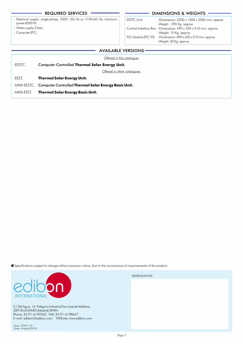
REQUIRED SERVICES DIMENSIONS & WEIGHTS
EESTC Unit: -Dimensions: 2200 x 1200 x 2005 mm. approx.-Weight : 290 Kg. approx.
Control Interface Box: -Dimensions: 490 x 330 x 310 mm. approx.-Weight: 10 Kg. approx.
PLC Module (PLC-PI): -Dimensions: 490 x 330 x 310 mm. approx.-Weight: 30 Kg. approx.
- Electrical supply: single-phase, 220V. /50 Hz or 110V/60 Hz, minimum power 6000 W.
- Water supply:2 bars.- Computer (PC).
Offered in this catalogue:
-EESTC. Computer Controlled Thermal Solar Energy Unit.
Offered in other catalogues:
-EEST. Thermal Solar Energy Unit.
-MINI-EESTC. Computer Controlled Thermal Solar Energy Basic Unit.
-MINI-EEST. Thermal Solar Energy Basic Unit.
AVAILABLE VERSIONS
Page 7


![1 2 4 N o rth V a n A v e n u e N A T IO N A L M A R IT IM ...€¦ · Co m m andant A llen on June 12, 2009 included in m y wr itten testim o ny as [E n closu re #1]. I furnish ed](https://img.pdfslide.us/doc/110x75/5f1447a5a7a28736a005c291/1-2-4-n-o-rth-v-a-n-a-v-e-n-u-e-n-a-t-io-n-a-l-m-a-r-it-im-co-m-m-andant-a-llen.jpg)