Embed Size (px)
Citation preview

Test Solutions Programming Manual
Appendices & Programming Examples

Important Notice This guide is owned by Mini-Circuits and is protected by copyright, trademark and other intellectual property laws. The information in this guide is provided by Mini-Circuits as an accommodation to our customers and may be used only to promote and accompany the purchase of Mini-Circuits’ Parts. This guide may not be reproduced, modified, distributed, published, stored in an electronic database, or transmitted and the information contained herein may not be exploited in any form or by any means, electronic, mechanical recording or otherwise, without prior written permission from Mini-Circuits. This guide is subject to change, qualifications, variations, adjustments or modifications without notice and may contain errors, omissions, inaccuracies, mistakes or deficiencies. Mini-Circuits assumes no responsibility for, and will have no liability on account of, any of the foregoing. Accordingly, this guide should be used as a guideline only. Trademarks Microsoft, Windows, Visual Basic, Visual C# and Visual C++ are registered trademarks of Microsoft Corporation. LabVIEW and CVI are registered trademarks of National Instruments Corporation. Delphi is a registered trademark of Delphi Technologies, Inc. MATLAB is a registered trademark of The MathWorks, Inc. Agilent VEE is a registered trademark of Agilent Technologies, Inc. Linux is a registered trademark of Linus Torvalds. Mac is a registered trademark of Apple Inc. Python is a registered trademark of Python Software Foundation Corporation. All other trademarks cited within this guide are the property of their respective owners. Neither Mini-Circuits nor the Mini-Circuits PTE (portable test equipment) series are affiliated with or endorsed or sponsored by the owners of the above referenced trademarks. Mini-Circuits and the Mini-Circuits logo are registered trademarks of Scientific Components Corporation. Mini-Circuits 13 Neptune Avenue Brooklyn, NY 11235, USA Phone: +1-718-934-4500 Email: [email protected] Web: www.minicircuits.com
Mini-Circuits Test Solutions Programming Manual Appendices 22-Sep-15 (A3)
Appendix A - Conversion Tables .................................................................. A-1
A1 - ASCII Character Codes ......................................................................................... A-1
Appendix B - Programming Examples .......................................................... B-1
B1 - Python Programming........................................................................................... B-1 B1a - USB Control with 32-Bit Python ..................................................................................... B-1
B1a.i - Power Sensor (Set Frequency/Read Power) ................................................... B-1 B1a.ii - Programmable Attenuator (Set/Read Attenuation) ...................................... B-2 B1a.iii - Programmable Attenuator (Set/Read Attenuation with User Input)............ B-3 B1a.iv - Switch Matrices (Set/Get Switch States Based on User Input) ..................... B-4
B1b - USB Control with 64-Bit Python ..................................................................................... B-6 B1b.i - Power Sensors ................................................................................................. B-6
B1c - Ethernet Control Using HTTP.......................................................................................... B-7 B1c.i - Switch Boxes (Set/Read Switch States) ........................................................... B-7 B1c.ii - Signal Generators (Set RF Output) ................................................................. B-9
B2 - C Programming.................................................................................................. B-11 B2a - USB Control in a Linux Environment ............................................................................ B-11
B2a.i - Switch Boxes .................................................................................................. B-12 B2a.ii - Synthesized Signal Generator ...................................................................... B-15 B2a.iii - Power Sensor (Single Device) ...................................................................... B-18 B2a.iv - Power Sensors (Controlling Multiple Devices) ............................................ B-21 B2a.v - Frequency Counter ....................................................................................... B-24 B2a.vi - Input/Output (IO) Control Boxes ................................................................. B-28 B2a.vii - Programmable Attenuator (Single Device) ................................................. B-31 B2a.viii - Programmable Attenuator (Single Device by Serial Number) ................... B-35 B2a.ix - Programmable Attenuators (Multiple Devices) .......................................... B-39
B3 - Visual Basic Programming ................................................................................. B-43 B3a - USB Control Using the ActiveX DLL .............................................................................. B-43
B3a.i - Synthesized Signal Generator ....................................................................... B-43 B3a.ii - Power Sensor................................................................................................ B-43 B3a.iii - Frequency Counter ...................................................................................... B-43 B3a.iv - Input/Output (IO) Control Boxes ................................................................. B-44 B3a.v - USB & RS232 to SPI Converters .................................................................... B-44 B3a.vi - Programmable Attenuators ......................................................................... B-44 B3a.vii - Switch Boxes ............................................................................................... B-45
B3b - RS232 Control .............................................................................................................. B-47 B3b.i - Programmable Attenuators .......................................................................... B-47 B3b.ii - RS232 to SPI Converters ............................................................................... B-48
B4 - C++ Programming .............................................................................................. B-50 B4a - USB Control Using the ActiveX DLL .............................................................................. B-50
B4a.i - Power Sensors ............................................................................................... B-50 B4a.ii - Synthesized Signal Generators ..................................................................... B-50 B4a.iii - Frequency Counter ...................................................................................... B-51 B4a.iv - Input/Output (IO) Control Boxes ................................................................. B-51 B4a.v - RS232 & USB to SPI Converters .................................................................... B-51 B4a.vi - Programmable Attenuators ......................................................................... B-52
B4b - Ethernet Control Using HTTP ....................................................................................... B-53 B4b.i - Signal Generators .......................................................................................... B-53
B5 - C# Programming ................................................................................................ B-55 B5a - USB Control Using the ActiveX DLL .............................................................................. B-55
Mini-Circuits Test Solutions Programming Manual Appendices 22-Sep-15 (A3)
B5a.i - Power Sensor ................................................................................................ B-55 B5a.ii - RS232 & USB to SPI Converter ..................................................................... B-55 B5a.iii - Programmable Attenuator .......................................................................... B-56 B5a.iv - Programmable Attenuator (2 Devices)........................................................ B-56
B5b - USB Control Using the .Net DLL ................................................................................... B-57 B5b.i - ZTM Series Modular Test Systems ................................................................ B-57 B5b.ii - Programmable Attenuator (2 Devices) ........................................................ B-58 B5b.iii - Power Sensor .............................................................................................. B-59
B5c - Ethernet Control Using HTTP........................................................................................ B-61 B5c.i - Switch Boxes .................................................................................................. B-61
B6 - Perl Programming ............................................................................................. B-62 B6a - USB Control with 32-Bit Perl ........................................................................................ B-62
B6a.i - Programmable Attenuator ............................................................................ B-62 B6b - USB Control with 64-Bit Perl ........................................................................................ B-63
B6b.i - ZTM Series Modular Test Systems ................................................................ B-63 B6c - Ethernet Control Using HTTP........................................................................................ B-64
B6c.i - ZTM Series Modular Test Systems ................................................................ B-64
B7 - LabVIEW Worked Examples ............................................................................... B-65 B7a - USB Control Using the ActiveX DLL .............................................................................. B-65
B7a.i - Power Sensors ............................................................................................... B-65 B7a.ii - Programmable Attenuators ......................................................................... B-72 B7a.iii - ZTM Series Modular Test Systems .............................................................. B-76
B7b - USB Control Using the .Net DLL ................................................................................... B-82 B7b.i - Programmable Attenuators .......................................................................... B-82
B7c - Ethernet Control Using HTTP........................................................................................ B-86 B7c.i - Switch Boxes .................................................................................................. B-86
B8 - MATLAB Worked Examples ............................................................................... B-88 B8a - USB Control Using the ActiveX DLL .............................................................................. B-88
B8a.i - Switch Boxes .................................................................................................. B-88 B8b - USB Control Using the .Net DLL ................................................................................... B-91
B8b.i - Switch Boxes ................................................................................................. B-91 B8b.ii - IO Control Boxes ........................................................................................... B-94
B9 - Agilent VEE Worked Examples ........................................................................... B-97 B9a - USB Control Using the ActiveX DLL .............................................................................. B-97
B9a.i - Switch Boxes .................................................................................................. B-97 B9b - USB Control Using the .Net DLL ................................................................................. B-100
B9b.i - Switch Boxes ............................................................................................... B-100
Appendix C - Troubleshooting ..................................................................... C-1
C1 - Working with the DLL Files .................................................................................. C-1 C1a - File Placement ................................................................................................................ C-1 C1b - Windows File Blocking ................................................................................................... C-2 C1c - File Registration .............................................................................................................. C-3
C1c.i - Successful Registration .................................................................................... C-4 C1c.ii - Common Registration Error Messages ........................................................... C-5
Mini-Circuits Portable Test Equipment Programming Manual A-1 Appendices 22-Sep-15 (A3)
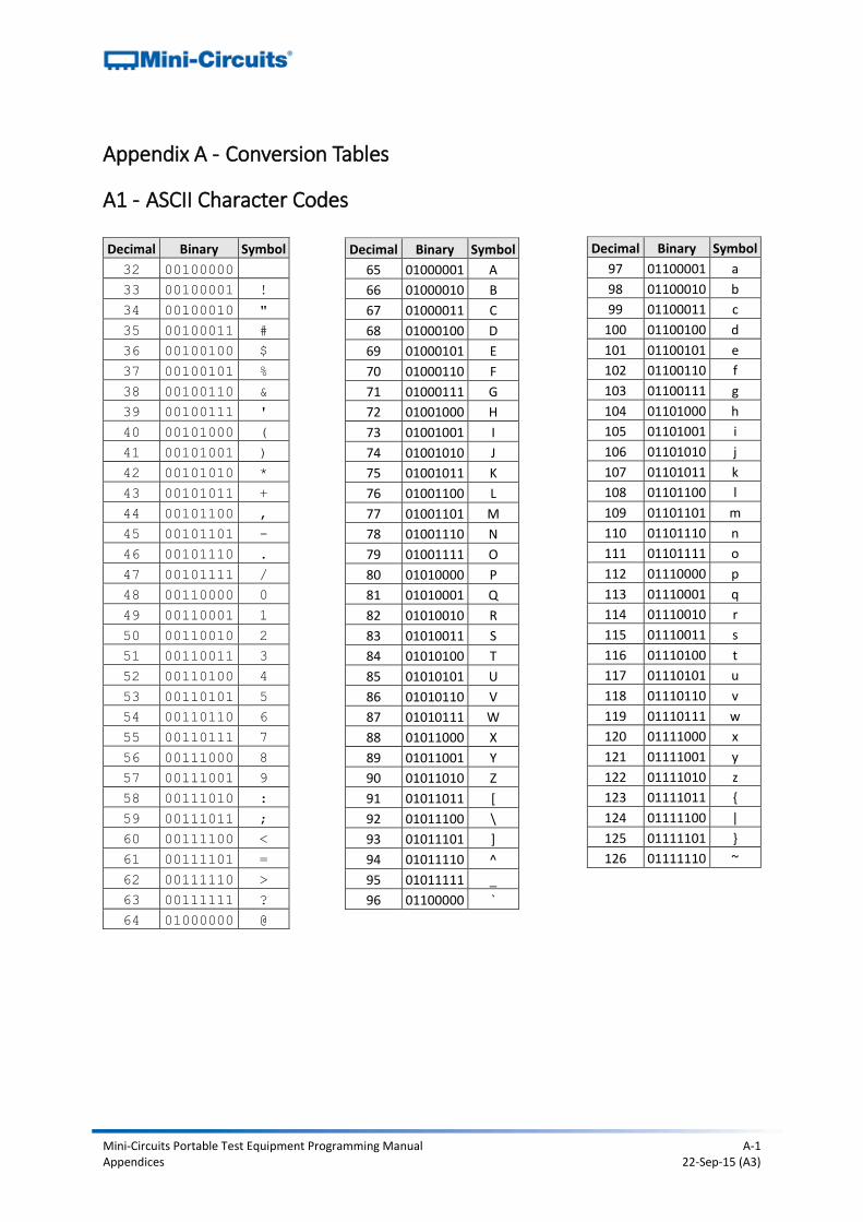
Appendix A - Conversion Tables
A1 - ASCII Character Codes
Decimal Binary Symbol
97 01100001 a
98 01100010 b
99 01100011 c
100 01100100 d
101 01100101 e
102 01100110 f
103 01100111 g
104 01101000 h
105 01101001 i
106 01101010 j
107 01101011 k
108 01101100 l
109 01101101 m
110 01101110 n
111 01101111 o
112 01110000 p
113 01110001 q
114 01110010 r
115 01110011 s
116 01110100 t
117 01110101 u
118 01110110 v
119 01110111 w
120 01111000 x
121 01111001 y
122 01111010 z
123 01111011 {
124 01111100 |
125 01111101 }
126 01111110 ~
Decimal Binary Symbol
32 00100000
33 00100001 !
34 00100010 "
35 00100011 #
36 00100100 $
37 00100101 %
38 00100110 &
39 00100111 '
40 00101000 (
41 00101001 )
42 00101010 *
43 00101011 +
44 00101100 ,
45 00101101 -
46 00101110 .
47 00101111 /
48 00110000 0
49 00110001 1
50 00110010 2
51 00110011 3
52 00110100 4
53 00110101 5
54 00110110 6
55 00110111 7
56 00111000 8
57 00111001 9
58 00111010 :
59 00111011 ;
60 00111100 <
61 00111101 =
62 00111110 >
63 00111111 ?
64 01000000 @
Decimal Binary Symbol
65 01000001 A
66 01000010 B
67 01000011 C
68 01000100 D
69 01000101 E
70 01000110 F
71 01000111 G
72 01001000 H
73 01001001 I
74 01001010 J
75 01001011 K
76 01001100 L
77 01001101 M
78 01001110 N
79 01001111 O
80 01010000 P
81 01010001 Q
82 01010010 R
83 01010011 S
84 01010100 T
85 01010101 U
86 01010110 V
87 01010111 W
88 01011000 X
89 01011001 Y
90 01011010 Z
91 01011011 [
92 01011100 \
93 01011101 ]
94 01011110 ^
95 01011111 _
96 01100000 `
Mini-Circuits Portable Test Equipment Programming Manual B-1 Appendices 22-Sep-15 (A3)
Appendix B - Programming Examples
B1 - Python Programming
B1a - USB Control with 32-Bit Python These examples demonstrate control of Mini-Circuits’ PTE products using Python in the following environment:
1. Host computer running a Windows operating system 2. PTE connected by the USB interface 3. Mini-Circuits ActiveX DLL installed and registered on the computer 4. Python for Windows extension (PyWin32) installed on the computer
Note: The Python for Windows extension, PyWin32, can be downloaded from:
http://sourceforge.net/projects/pywin32/files/pywin32/Build%20217/
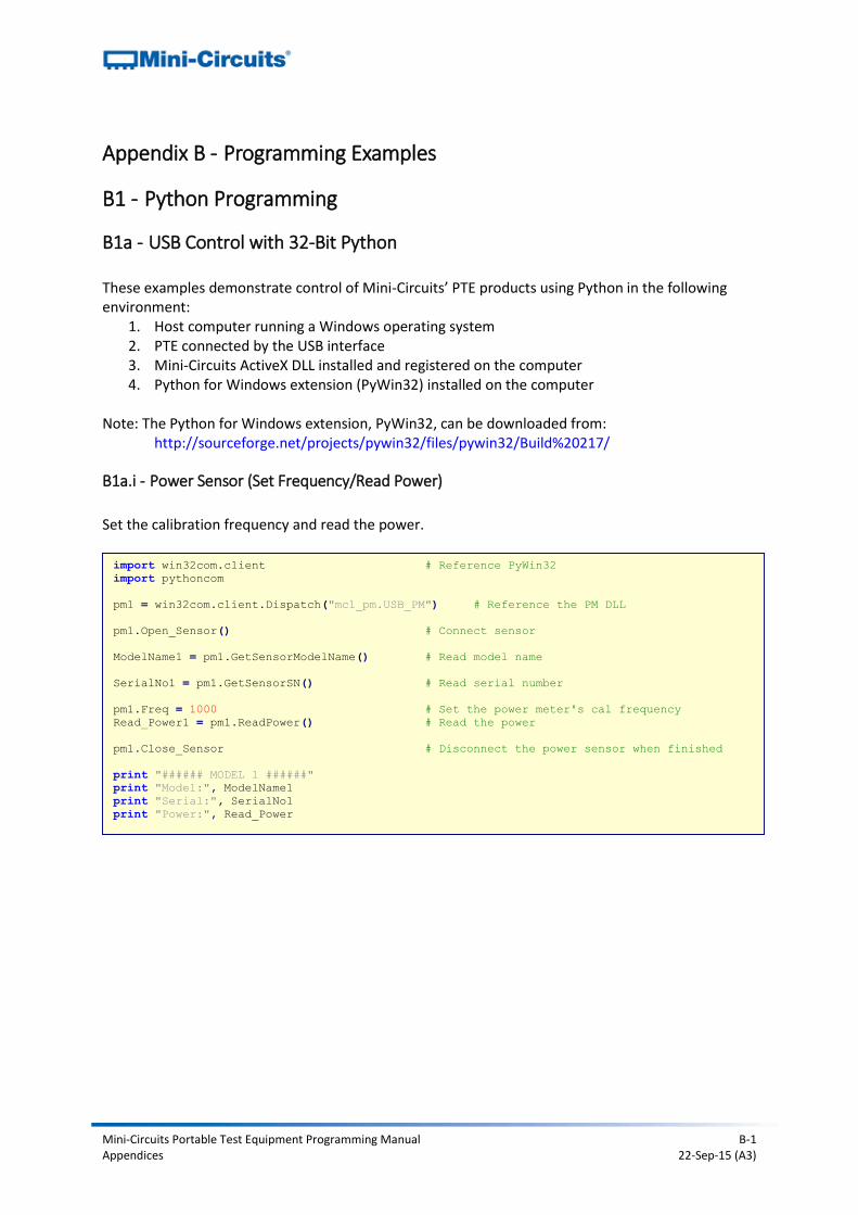
B1a.i - Power Sensor (Set Frequency/Read Power)
Set the calibration frequency and read the power.
import win32com.client # Reference PyWin32
import pythoncom
pm1 = win32com.client.Dispatch("mcl_pm.USB_PM") # Reference the PM DLL
pm1.Open_Sensor() # Connect sensor
ModelName1 = pm1.GetSensorModelName() # Read model name
SerialNo1 = pm1.GetSensorSN() # Read serial number
pm1.Freq = 1000 # Set the power meter's cal frequency
Read_Power1 = pm1.ReadPower() # Read the power
pm1.Close_Sensor # Disconnect the power sensor when finished
print "###### MODEL 1 ######"
print "Model:", ModelName1
print "Serial:", SerialNo1
print "Power:", Read_Power
Mini-Circuits Portable Test Equipment Programming Manual B-2 Appendices 22-Sep-15 (A3)
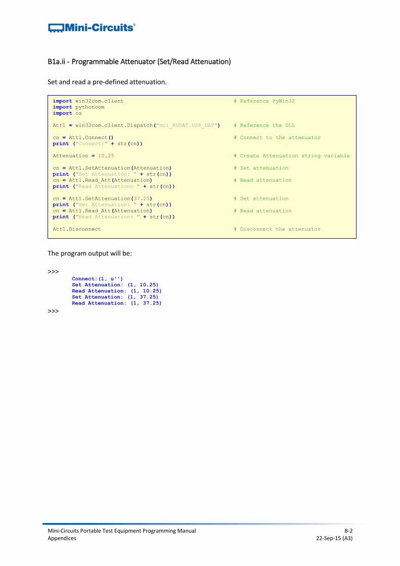
B1a.ii - Programmable Attenuator (Set/Read Attenuation)
Set and read a pre-defined attenuation.
The program output will be: >>>
Connect:(1, u'')
Set Attenuation: (1, 10.25)
Read Attenuation: (1, 10.25)
Set Attenuation: (1, 37.25)
Read Attenuation: (1, 37.25)
>>>
import win32com.client # Reference PyWin32
import pythoncom
import os
Att1 = win32com.client.Dispatch("mcl_RUDAT.USB_DAT") # Reference the DLL
cn = Att1.Connect() # Connect to the attenuator
print ("Connect:" + str(cn))
Attenuation = 10.25 # Create Attenuation string variable
cn = Att1.SetAttenuation(Attenuation) # Set attenuation
print ("Set Attenuation: " + str(cn))
cn = Att1.Read_Att(Attenuation) # Read attenuation
print ("Read Attenuation: " + str(cn))
cn = Att1.SetAttenuation(37.25) # Set attenuation
print ("Set Attenuation: " + str(cn))
cn = Att1.Read_Att(Attenuation) # Read attenuation
print ("Read Attenuation: " + str(cn))
Att1.Disconnect # Disconnect the attenuator
Mini-Circuits Portable Test Equipment Programming Manual B-3 Appendices 22-Sep-15 (A3)
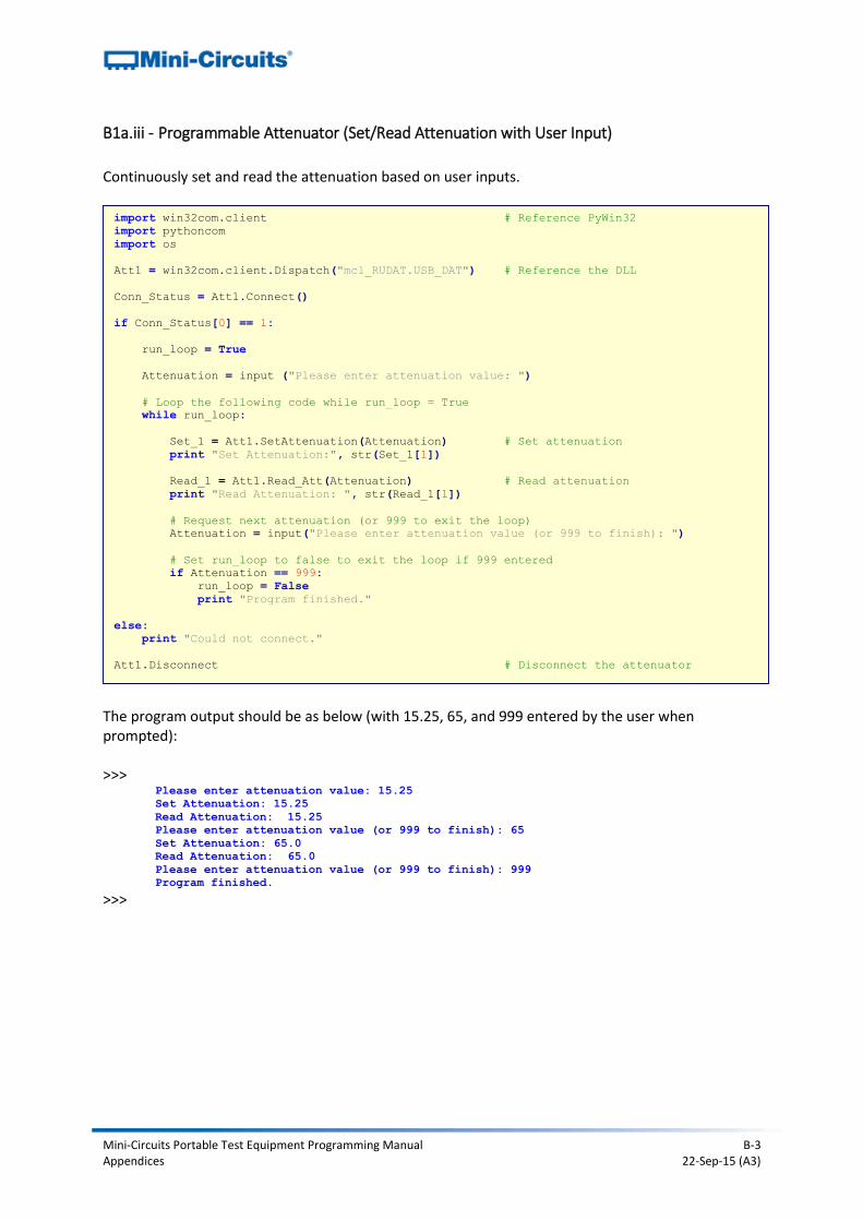
B1a.iii - Programmable Attenuator (Set/Read Attenuation with User Input)
Continuously set and read the attenuation based on user inputs.
The program output should be as below (with 15.25, 65, and 999 entered by the user when prompted): >>>
Please enter attenuation value: 15.25
Set Attenuation: 15.25
Read Attenuation: 15.25
Please enter attenuation value (or 999 to finish): 65
Set Attenuation: 65.0
Read Attenuation: 65.0
Please enter attenuation value (or 999 to finish): 999
Program finished.
>>>
import win32com.client # Reference PyWin32
import pythoncom
import os
Att1 = win32com.client.Dispatch("mcl_RUDAT.USB_DAT") # Reference the DLL
Conn_Status = Att1.Connect()
if Conn_Status[0] == 1:
run_loop = True
Attenuation = input ("Please enter attenuation value: ")
# Loop the following code while run_loop = True
while run_loop:
Set_1 = Att1.SetAttenuation(Attenuation) # Set attenuation
print "Set Attenuation:", str(Set_1[1])
Read_1 = Att1.Read_Att(Attenuation) # Read attenuation
print "Read Attenuation: ", str(Read_1[1])
# Request next attenuation (or 999 to exit the loop)
Attenuation = input("Please enter attenuation value (or 999 to finish): ")
# Set run_loop to false to exit the loop if 999 entered
if Attenuation == 999:
run_loop = False
print "Program finished."
else:
print "Could not connect."
Att1.Disconnect # Disconnect the attenuator
Mini-Circuits Portable Test Equipment Programming Manual B-4 Appendices 22-Sep-15 (A3)
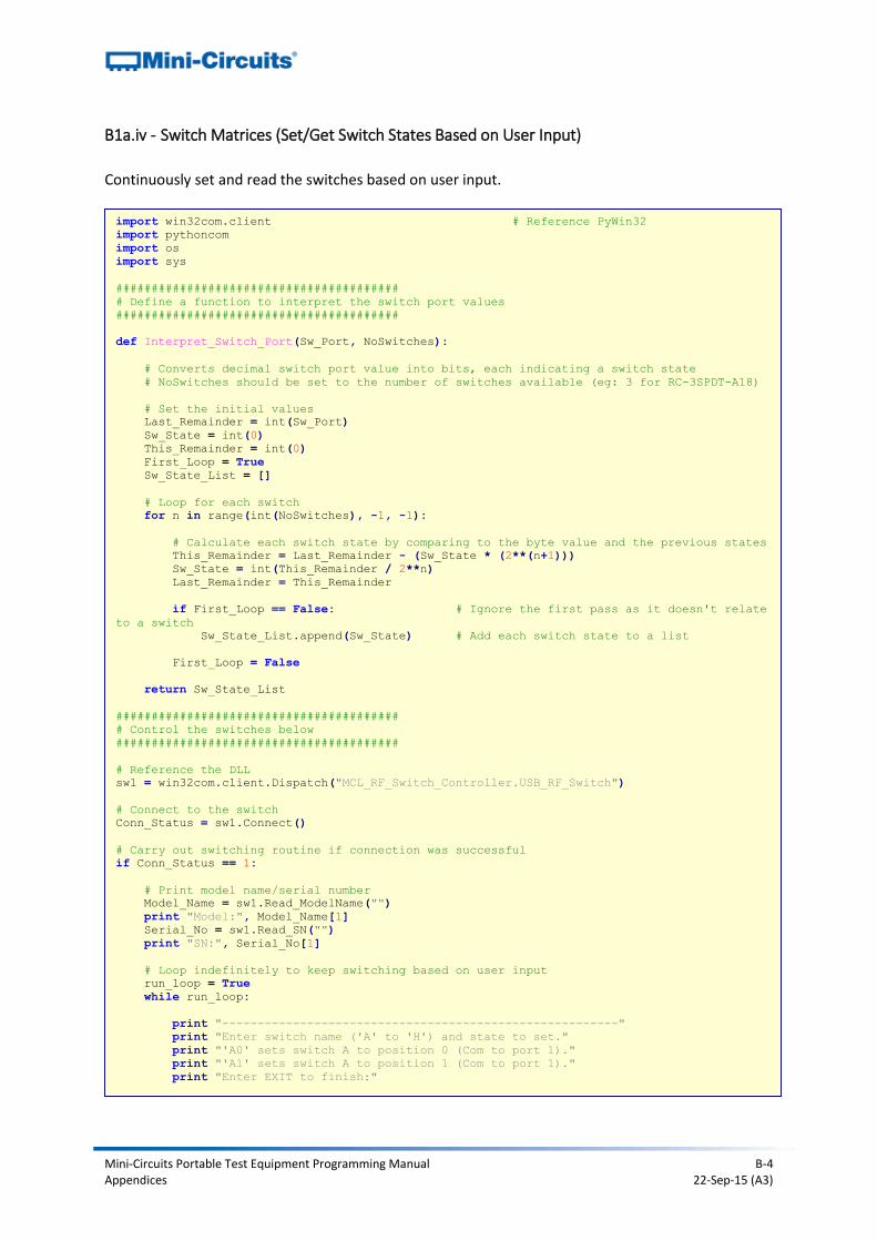
B1a.iv - Switch Matrices (Set/Get Switch States Based on User Input)
Continuously set and read the switches based on user input.
import win32com.client # Reference PyWin32
import pythoncom
import os
import sys
########################################
# Define a function to interpret the switch port values
########################################
def Interpret_Switch_Port(Sw_Port, NoSwitches):
# Converts decimal switch port value into bits, each indicating a switch state
# NoSwitches should be set to the number of switches available (eg: 3 for RC-3SPDT-A18)
# Set the initial values
Last_Remainder = int(Sw_Port)
Sw_State = int(0)
This_Remainder = int(0)
First_Loop = True
Sw_State_List = []
# Loop for each switch
for n in range(int(NoSwitches), -1, -1):
# Calculate each switch state by comparing to the byte value and the previous states
This_Remainder = Last_Remainder - (Sw_State * (2**(n+1)))
Sw_State = int(This_Remainder / 2**n)
Last_Remainder = This_Remainder
if First_Loop == False: # Ignore the first pass as it doesn't relate
to a switch
Sw_State_List.append(Sw_State) # Add each switch state to a list
First_Loop = False
return Sw_State_List
########################################
# Control the switches below
########################################
# Reference the DLL
sw1 = win32com.client.Dispatch("MCL_RF_Switch_Controller.USB_RF_Switch")
# Connect to the switch
Conn_Status = sw1.Connect()
# Carry out switching routine if connection was successful
if Conn_Status == 1:
# Print model name/serial number
Model_Name = sw1.Read_ModelName("")
print "Model:", Model_Name[1]
Serial_No = sw1.Read_SN("")
print "SN:", Serial_No[1]
# Loop indefinitely to keep switching based on user input
run_loop = True
while run_loop:
print "--------------------------------------------------------"
print "Enter switch name ('A' to 'H') and state to set."
print "'A0' sets switch A to position 0 (Com to port 1)."
print "'A1' sets switch A to position 1 (Com to port 1)."
print "Enter EXIT to finish:"
Mini-Circuits Portable Test Equipment Programming Manual B-5 Appendices 22-Sep-15 (A3)
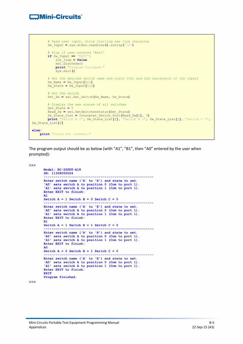
The program output should be as below (with “A1”, “B1”, then “A0” entered by the user when prompted): >>>
Model: RC-2SPDT-A18
SN: 11308050024
--------------------------------------------------------
Enter switch name ('A' to 'H') and state to set.
'A0' sets switch A to position 0 (Com to port 1).
'A1' sets switch A to position 1 (Com to port 1).
Enter EXIT to finish:
A1
Switch A = 1 Switch B = 0 Switch C = 0
--------------------------------------------------------
Enter switch name ('A' to 'H') and state to set.
'A0' sets switch A to position 0 (Com to port 1).
'A1' sets switch A to position 1 (Com to port 1).
Enter EXIT to finish:
B1
Switch A = 1 Switch B = 1 Switch C = 0
--------------------------------------------------------
Enter switch name ('A' to 'H') and state to set.
'A0' sets switch A to position 0 (Com to port 1).
'A1' sets switch A to position 1 (Com to port 1).
Enter EXIT to finish:
A0
Switch A = 0 Switch B = 1 Switch C = 0
--------------------------------------------------------
Enter switch name ('A' to 'H') and state to set.
'A0' sets switch A to position 0 (Com to port 1).
'A1' sets switch A to position 1 (Com to port 1).
Enter EXIT to finish:
EXIT
Program finished.
>>>
# Read user input, strip trailing new line character
Sw_Input = sys.stdin.readline().rstrip('\n')
# Stop if user entered 'Exit'
if Sw_Input == 'EXIT':
run_loop = False
sw1.Disconnect
print "Program finished."
sys.exit()
# Get the desired switch name and state (1st and 2nd characters of the input)
Sw_Name = Sw_Input[0:1]
Sw_State = Sw_Input[1:2]
# Set the switch
Set_Sw = sw1.Set_Switch(Sw_Name, Sw_State)
# Display the new states of all switches
Set_State = 0
Read_Sw = sw1.GetSwitchesStatus(Set_State)
Sw_State_List = Interpret_Switch_Port(Read_Sw[1], 3)
print "Switch A =", Sw_State_List[2], "Switch B =", Sw_State_List[1], "Switch C =",
Sw_State_List[0]
else:
print "Could not connect."
Mini-Circuits Portable Test Equipment Programming Manual B-6 Appendices 22-Sep-15 (A3)
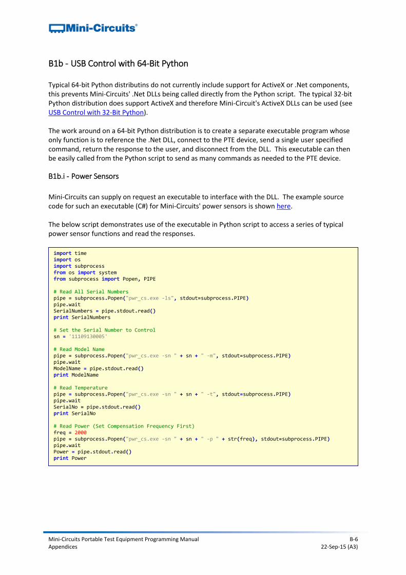
B1b - USB Control with 64-Bit Python Typical 64-bit Python distributins do not currently include support for ActiveX or .Net components, this prevents Mini-Circuits' .Net DLLs being called directly from the Python script. The typical 32-bit Python distribution does support ActiveX and therefore Mini-Circuit's ActiveX DLLs can be used (see USB Control with 32-Bit Python). The work around on a 64-bit Python distribution is to create a separate executable program whose only function is to reference the .Net DLL, connect to the PTE device, send a single user specified command, return the response to the user, and disconnect from the DLL. This executable can then be easily called from the Python script to send as many commands as needed to the PTE device.
B1b.i - Power Sensors
Mini-Circuits can supply on request an executable to interface with the DLL. The example source code for such an executable (C#) for Mini-Circuits' power sensors is shown here. The below script demonstrates use of the executable in Python script to access a series of typical power sensor functions and read the responses.
import time import os import subprocess from os import system from subprocess import Popen, PIPE # Read All Serial Numbers pipe = subprocess.Popen("pwr_cs.exe -ls", stdout=subprocess.PIPE) pipe.wait SerialNumbers = pipe.stdout.read() print SerialNumbers # Set the Serial Number to Control sn = '11109130005' # Read Model Name pipe = subprocess.Popen("pwr_cs.exe -sn " + sn + " -m", stdout=subprocess.PIPE) pipe.wait ModelName = pipe.stdout.read() print ModelName # Read Temperature pipe = subprocess.Popen("pwr_cs.exe -sn " + sn + " -t", stdout=subprocess.PIPE) pipe.wait SerialNo = pipe.stdout.read() print SerialNo # Read Power (Set Compensation Frequency First) freq = 2000 pipe = subprocess.Popen("pwr_cs.exe -sn " + sn + " -p " + str(freq), stdout=subprocess.PIPE) pipe.wait Power = pipe.stdout.read() print Power
Mini-Circuits Portable Test Equipment Programming Manual B-7 Appendices 22-Sep-15 (A3)
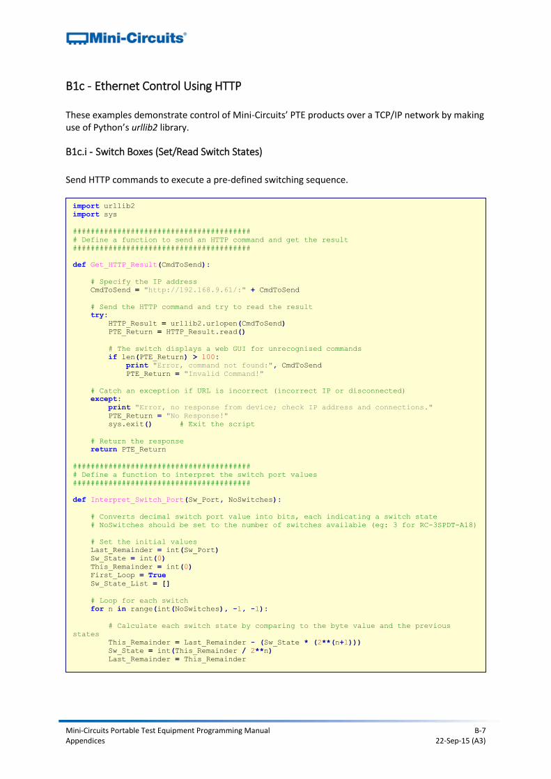
B1c - Ethernet Control Using HTTP These examples demonstrate control of Mini-Circuits’ PTE products over a TCP/IP network by making use of Python’s urllib2 library.
B1c.i - Switch Boxes (Set/Read Switch States)
Send HTTP commands to execute a pre-defined switching sequence.
import urllib2
import sys
########################################
# Define a function to send an HTTP command and get the result
########################################
def Get_HTTP_Result(CmdToSend):
# Specify the IP address
CmdToSend = "http://192.168.9.61/:" + CmdToSend
# Send the HTTP command and try to read the result
try:
HTTP_Result = urllib2.urlopen(CmdToSend)
PTE_Return = HTTP_Result.read()
# The switch displays a web GUI for unrecognised commands
if len(PTE_Return) > 100:
print "Error, command not found:", CmdToSend
PTE_Return = "Invalid Command!"
# Catch an exception if URL is incorrect (incorrect IP or disconnected)
except:
print "Error, no response from device; check IP address and connections."
PTE_Return = "No Response!"
sys.exit() # Exit the script
# Return the response
return PTE_Return
########################################
# Define a function to interpret the switch port values
########################################
def Interpret_Switch_Port(Sw_Port, NoSwitches):
# Converts decimal switch port value into bits, each indicating a switch state
# NoSwitches should be set to the number of switches available (eg: 3 for RC-3SPDT-A18)
# Set the initial values
Last_Remainder = int(Sw_Port)
Sw_State = int(0)
This_Remainder = int(0)
First_Loop = True
Sw_State_List = []
# Loop for each switch
for n in range(int(NoSwitches), -1, -1):
# Calculate each switch state by comparing to the byte value and the previous
states
This_Remainder = Last_Remainder - (Sw_State * (2**(n+1)))
Sw_State = int(This_Remainder / 2**n)
Last_Remainder = This_Remainder
Mini-Circuits Portable Test Equipment Programming Manual B-8 Appendices 22-Sep-15 (A3)
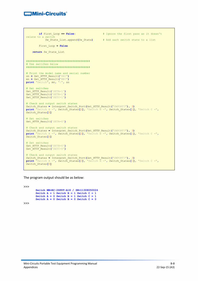
The program output should be as below: >>>
Switch MN=RC-2SPDT-A18 / SN=11308050024
Switch A = 1 Switch B = 1 Switch C = 1
Switch A = 0 Switch B = 1 Switch C = 1
Switch A = 0 Switch B = 0 Switch C = 0
>>>
if First_Loop == False: # Ignore the first pass as it doesn't
relate to a switch
Sw_State_List.append(Sw_State) # Add each switch state to a list
First_Loop = False
return Sw_State_List
########################################
# Use switches below
########################################
# Print the model name and serial number
sn = Get_HTTP_Result("SN?")
mn = Get_HTTP_Result("MN?")
print "Switch", mn, "/", sn
# Set switches
Get_HTTP_Result('SETA=1')
Get_HTTP_Result('SETB=1')
Get_HTTP_Result('SETC=1')
# Check and output switch states
Switch_States = Interpret_Switch_Port(Get_HTTP_Result("SWPORT?"), 3)
print "Switch A =", Switch_States[2], "Switch B =", Switch_States[1], "Switch C =",
Switch_States[0]
# Set switches
Get_HTTP_Result('SETA=0')
# Check and output switch states
Switch_States = Interpret_Switch_Port(Get_HTTP_Result("SWPORT?"), 3)
print "Switch A =", Switch_States[2], "Switch B =", Switch_States[1], "Switch C =",
Switch_States[0]
# Set switches
Get_HTTP_Result('SETB=0')
Get_HTTP_Result('SETC=0')
# Check and output switch states
Switch_States = Interpret_Switch_Port(Get_HTTP_Result("SWPORT?"), 3)
print "Switch A =", Switch_States[2], "Switch B =", Switch_States[1], "Switch C =",
Switch_States[0]
Mini-Circuits Portable Test Equipment Programming Manual B-9 Appendices 22-Sep-15 (A3)
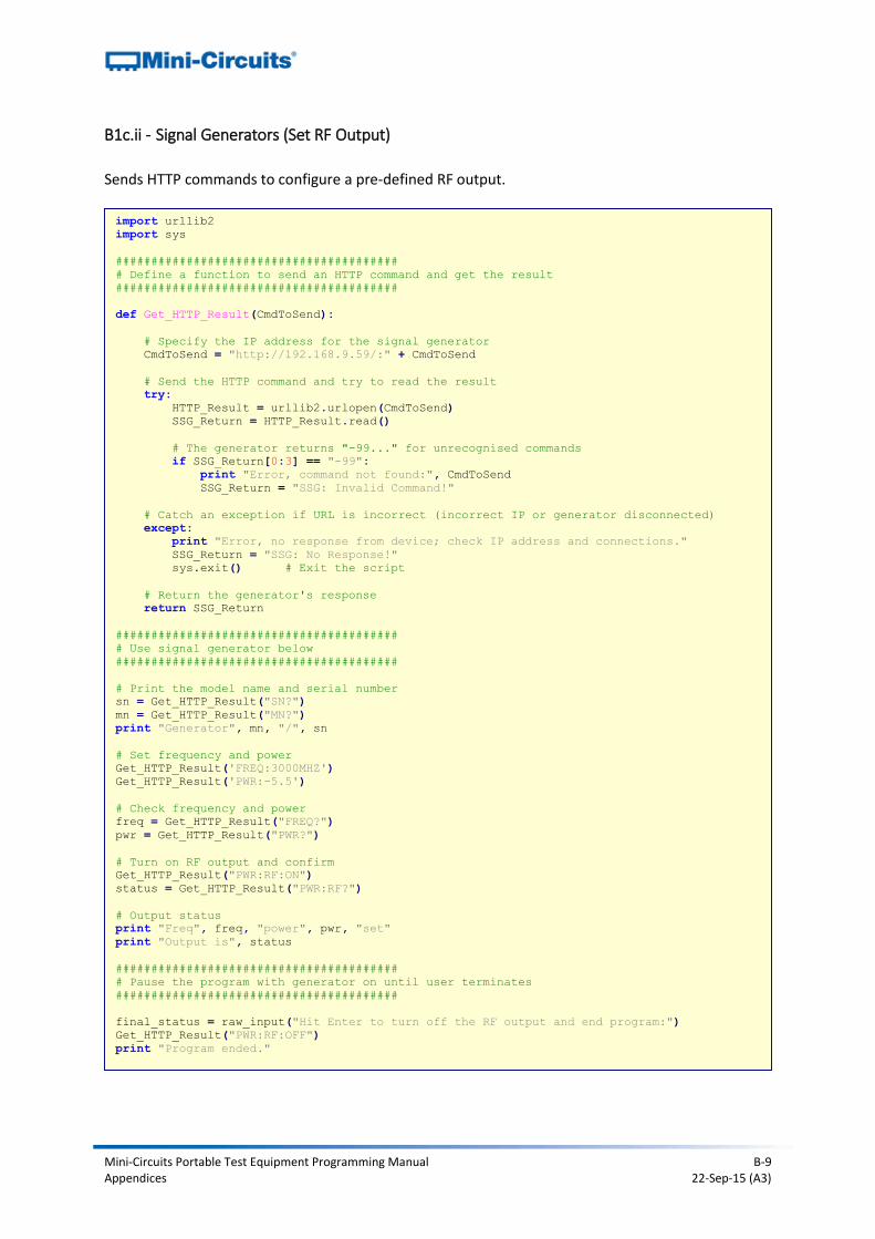
B1c.ii - Signal Generators (Set RF Output)
Sends HTTP commands to configure a pre-defined RF output.
import urllib2
import sys
########################################
# Define a function to send an HTTP command and get the result
########################################
def Get_HTTP_Result(CmdToSend):
# Specify the IP address for the signal generator
CmdToSend = "http://192.168.9.59/:" + CmdToSend
# Send the HTTP command and try to read the result
try:
HTTP_Result = urllib2.urlopen(CmdToSend)
SSG_Return = HTTP_Result.read()
# The generator returns "-99..." for unrecognised commands
if SSG_Return[0:3] == "-99":
print "Error, command not found:", CmdToSend
SSG_Return = "SSG: Invalid Command!"
# Catch an exception if URL is incorrect (incorrect IP or generator disconnected)
except:
print "Error, no response from device; check IP address and connections."
SSG_Return = "SSG: No Response!"
sys.exit() # Exit the script
# Return the generator's response
return SSG_Return
########################################
# Use signal generator below
########################################
# Print the model name and serial number
sn = Get_HTTP_Result("SN?")
mn = Get_HTTP_Result("MN?")
print "Generator", mn, "/", sn
# Set frequency and power
Get_HTTP_Result('FREQ:3000MHZ')
Get_HTTP_Result('PWR:-5.5')
# Check frequency and power
freq = Get_HTTP_Result("FREQ?")
pwr = Get_HTTP_Result("PWR?")
# Turn on RF output and confirm
Get_HTTP_Result("PWR:RF:ON")
status = Get_HTTP_Result("PWR:RF?")
# Output status
print "Freq", freq, "power", pwr, "set"
print "Output is", status
########################################
# Pause the program with generator on until user terminates
########################################
final_status = raw_input("Hit Enter to turn off the RF output and end program:")
Get_HTTP_Result("PWR:RF:OFF")
print "Program ended."
Mini-Circuits Portable Test Equipment Programming Manual B-10 Appendices 22-Sep-15 (A3)
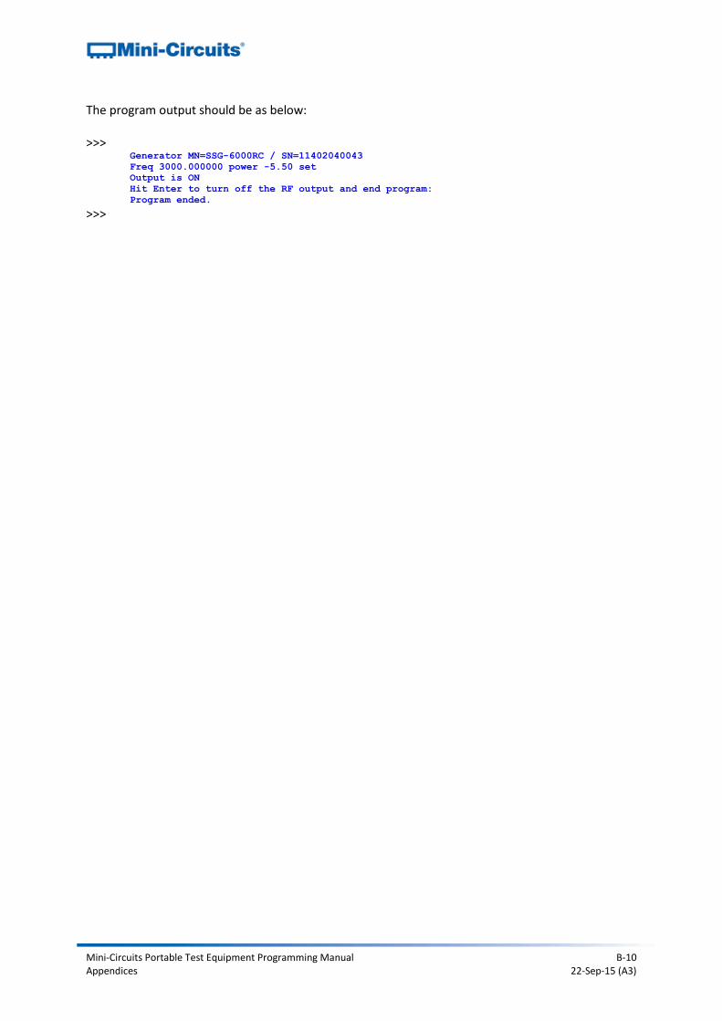
The program output should be as below: >>>
Generator MN=SSG-6000RC / SN=11402040043
Freq 3000.000000 power -5.50 set
Output is ON
Hit Enter to turn off the RF output and end program:
Program ended.
>>>
Mini-Circuits Portable Test Equipment Programming Manual B-11 Appendices 22-Sep-15 (A3)
B2 - C Programming
B2a - USB Control in a Linux Environment These examples demonstrate control of Mini-Circuits’ PTE products using C in the following environment:
1. Host computer running a Linux operating system 2. PTE connected by the USB interface 3. Linux’s libhid/libusb libraries installed
The examples use Linux’s libhid and libusb libraries to allow communication with the PTE as a USB Human Interface Device. The package can be downloaded from the Mini-Circuits website with the programming example files, installation can be carried out in the following steps:
1. Download libhid-0.2.16.tar.gz 2. Extract libhid-0.2.16.tar.gz to a temporary folder 3. Open the Terminal on the temporary folder location 4. Type the following commands:
a. sudo apt-get install libusb-dev b. cd libhid-0.2.16 c. ./configure --enable-werror=no d. make e. sudo make install f. sudo ldconfig
Mini-Circuits Portable Test Equipment Programming Manual B-12 Appendices 22-Sep-15 (A3)
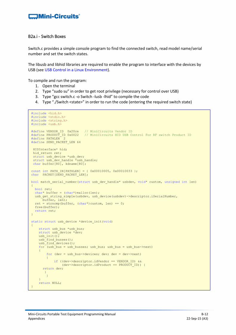
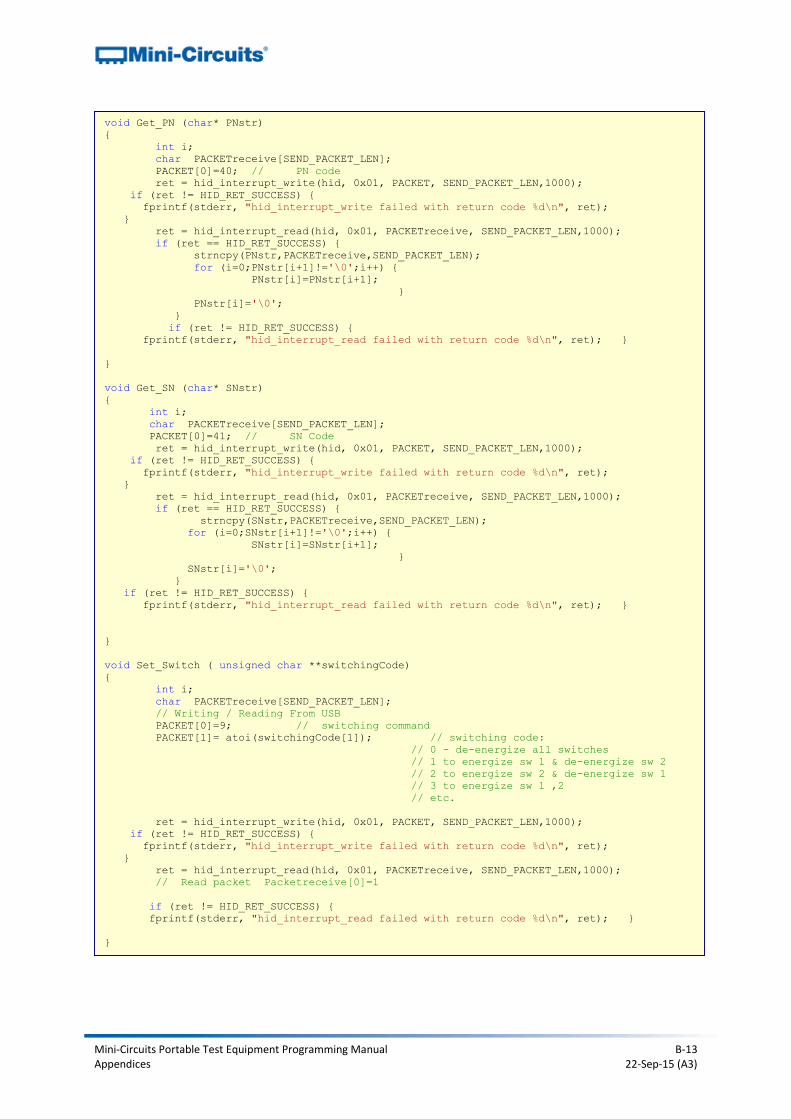
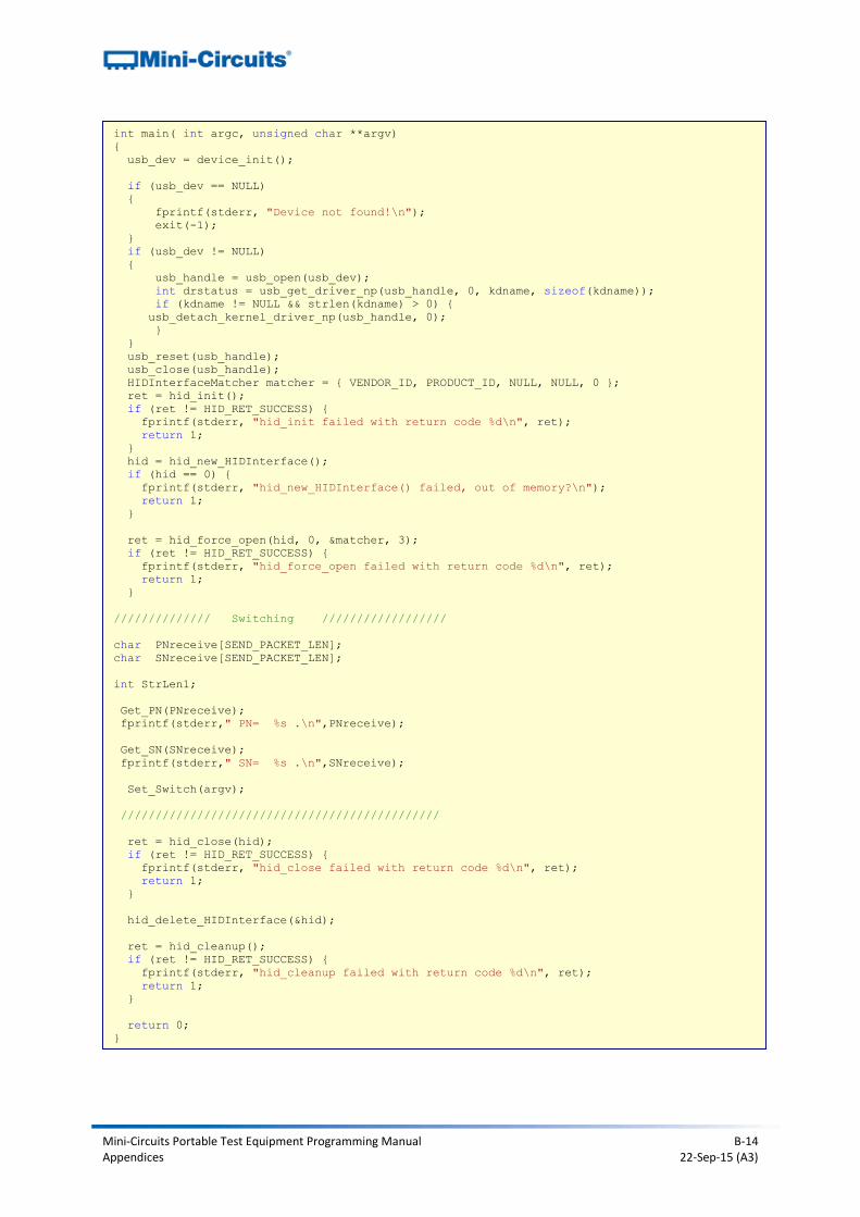
B2a.i - Switch Boxes
Switch.c provides a simple console program to find the connected switch, read model name/serial number and set the switch states. The libusb and libhid libraries are required to enable the program to interface with the devices by USB (see USB Control in a Linux Environment). To compile and run the program:
1. Open the terminal 2. Type “sudo su” in order to get root privilege (necessary for control over USB) 3. Type “gcc switch.c -o Switch -lusb -lhid” to compile the code 4. Type “./Switch <state>” in order to run the code (entering the required switch state)
#include <hid.h>
#include <stdio.h>
#include <string.h>
#include <usb.h>
#define VENDOR_ID 0x20ce // MiniCircuits Vendor ID
#define PRODUCT_ID 0x0022 // MiniCircuits HID USB Control For RF switch Product ID
#define PATHLEN 2
#define SEND_PACKET_LEN 64
HIDInterface* hid;
hid_return ret;
struct usb_device *usb_dev;
struct usb_dev_handle *usb_handle;
char buffer[80], kdname[80];
const int PATH_IN[PATHLEN] = { 0x00010005, 0x00010033 };
char PACKET[SEND_PACKET_LEN];
bool match_serial_number(struct usb_dev_handle* usbdev, void* custom, unsigned int len)
{
bool ret;
char* buffer = (char*)malloc(len);
usb_get_string_simple(usbdev, usb_device(usbdev)->descriptor.iSerialNumber,
buffer, len);
ret = strncmp(buffer, (char*)custom, len) == 0;
free(buffer);
return ret;
}
static struct usb_device *device_init(void)
{
struct usb_bus *usb_bus;
struct usb_device *dev;
usb_init();
usb_find_busses();
usb_find_devices();
for (usb_bus = usb_busses; usb_bus; usb_bus = usb_bus->next)
{
for (dev = usb_bus->devices; dev; dev = dev->next)
{
if ((dev->descriptor.idVendor == VENDOR_ID) &&
(dev->descriptor.idProduct == PRODUCT_ID)) {
return dev;
}
}
}
return NULL;
}
Mini-Circuits Portable Test Equipment Programming Manual B-13 Appendices 22-Sep-15 (A3)
void Get_PN (char* PNstr)
{
int i;
char PACKETreceive[SEND_PACKET_LEN];
PACKET[0]=40; // PN code
ret = hid_interrupt_write(hid, 0x01, PACKET, SEND_PACKET_LEN,1000);
if (ret != HID_RET_SUCCESS) {
fprintf(stderr, "hid_interrupt_write failed with return code %d\n", ret);
}
ret = hid_interrupt_read(hid, 0x01, PACKETreceive, SEND_PACKET_LEN,1000);
if (ret == HID_RET_SUCCESS) {
strncpy(PNstr,PACKETreceive,SEND_PACKET_LEN);
for (i=0;PNstr[i+1]!='\0';i++) {
PNstr[i]=PNstr[i+1];
}
PNstr[i]='\0';
}
if (ret != HID_RET_SUCCESS) {
fprintf(stderr, "hid_interrupt_read failed with return code %d\n", ret); }
}
void Get_SN (char* SNstr)
{
int i;
char PACKETreceive[SEND_PACKET_LEN];
PACKET[0]=41; // SN Code
ret = hid_interrupt_write(hid, 0x01, PACKET, SEND_PACKET_LEN,1000);
if (ret != HID_RET_SUCCESS) {
fprintf(stderr, "hid_interrupt_write failed with return code %d\n", ret);
}
ret = hid_interrupt_read(hid, 0x01, PACKETreceive, SEND_PACKET_LEN,1000);
if (ret == HID_RET_SUCCESS) {
strncpy(SNstr,PACKETreceive,SEND_PACKET_LEN);
for (i=0;SNstr[i+1]!='\0';i++) {
SNstr[i]=SNstr[i+1];
}
SNstr[i]='\0';
}
if (ret != HID_RET_SUCCESS) {
fprintf(stderr, "hid_interrupt_read failed with return code %d\n", ret); }
}
void Set_Switch ( unsigned char **switchingCode)
{
int i;
char PACKETreceive[SEND_PACKET_LEN];
// Writing / Reading From USB
PACKET[0]=9; // switching command
PACKET[1]= atoi(switchingCode[1]); // switching code:
// 0 - de-energize all switches
// 1 to energize sw 1 & de-energize sw 2
// 2 to energize sw 2 & de-energize sw 1
// 3 to energize sw 1 ,2
// etc.
ret = hid_interrupt_write(hid, 0x01, PACKET, SEND_PACKET_LEN,1000);
if (ret != HID_RET_SUCCESS) {
fprintf(stderr, "hid_interrupt_write failed with return code %d\n", ret);
}
ret = hid_interrupt_read(hid, 0x01, PACKETreceive, SEND_PACKET_LEN,1000);
// Read packet Packetreceive[0]=1
if (ret != HID_RET_SUCCESS) {
fprintf(stderr, "hid_interrupt_read failed with return code %d\n", ret); }
}
Mini-Circuits Portable Test Equipment Programming Manual B-14 Appendices 22-Sep-15 (A3)
int main( int argc, unsigned char **argv)
{
usb_dev = device_init();
if (usb_dev == NULL)
{
fprintf(stderr, "Device not found!\n");
exit(-1);
}
if (usb_dev != NULL)
{
usb_handle = usb_open(usb_dev);
int drstatus = usb_get_driver_np(usb_handle, 0, kdname, sizeof(kdname));
if (kdname != NULL && strlen(kdname) > 0) {
usb_detach_kernel_driver_np(usb_handle, 0);
}
}
usb_reset(usb_handle);
usb_close(usb_handle);
HIDInterfaceMatcher matcher = { VENDOR_ID, PRODUCT_ID, NULL, NULL, 0 };
ret = hid_init();
if (ret != HID_RET_SUCCESS) {
fprintf(stderr, "hid_init failed with return code %d\n", ret);
return 1;
}
hid = hid_new_HIDInterface();
if (hid == 0) {
fprintf(stderr, "hid_new_HIDInterface() failed, out of memory?\n");
return 1;
}
ret = hid_force_open(hid, 0, &matcher, 3);
if (ret != HID_RET_SUCCESS) {
fprintf(stderr, "hid_force_open failed with return code %d\n", ret);
return 1;
}
////////////// Switching //////////////////
char PNreceive[SEND_PACKET_LEN];
char SNreceive[SEND_PACKET_LEN];
int StrLen1;
Get_PN(PNreceive);
fprintf(stderr," PN= %s .\n",PNreceive);
Get_SN(SNreceive);
fprintf(stderr," SN= %s .\n",SNreceive);
Set_Switch(argv);
//////////////////////////////////////////////
ret = hid_close(hid);
if (ret != HID_RET_SUCCESS) {
fprintf(stderr, "hid_close failed with return code %d\n", ret);
return 1;
}
hid_delete_HIDInterface(&hid);
ret = hid_cleanup();
if (ret != HID_RET_SUCCESS) {
fprintf(stderr, "hid_cleanup failed with return code %d\n", ret);
return 1;
}
return 0;
}

Mini-Circuits Portable Test Equipment Programming Manual B-15 Appendices 22-Sep-15 (A3)
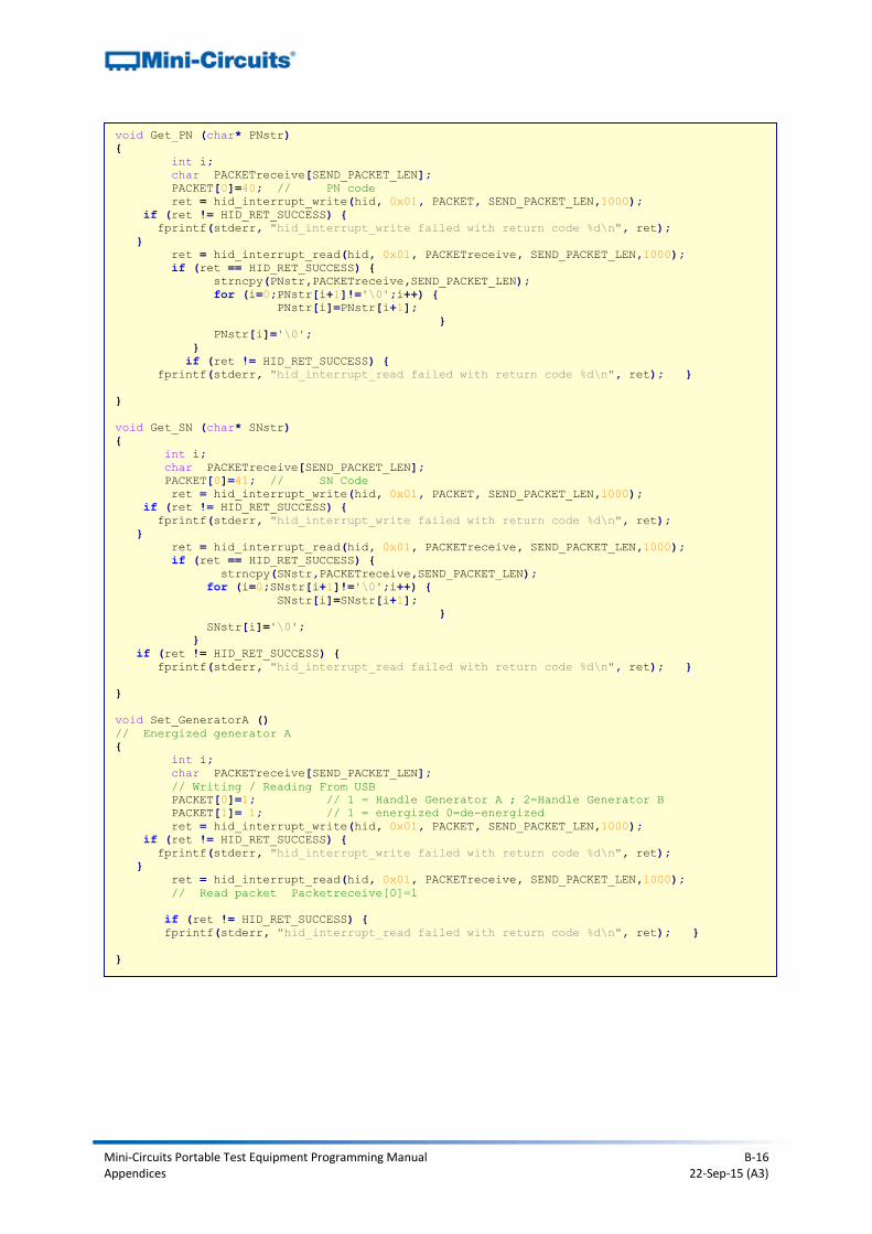
B2a.ii - Synthesized Signal Generator
Find connected signal generator, read model name/serial number and set RF output.
/* ******************************************************************
This is an example code to communicate with USB Control Driver for RF generator.
The example use libusb and libhid libraries to connect to the USB ,
and are available to downlolad from the web (GNU GPL license ).
*********************************************************************/
#include <hid.h>
#include <stdio.h>
#include <string.h>
#include <usb.h>
#define VENDOR_ID 0x20ce // MiniCircuits Vendor ID
#define PRODUCT_ID 0x0022 // MiniCircuits HID USB Control For RF generator Product ID
#define PATHLEN 2
#define SEND_PACKET_LEN 64
HIDInterface* hid;
hid_return ret;
struct usb_device *usb_dev;
struct usb_dev_handle *usb_handle;
char buffer[80], kdname[80];
const int PATH_IN[PATHLEN] = { 0x00010005, 0x00010033 };
char PACKET[SEND_PACKET_LEN];
bool match_serial_number(struct usb_dev_handle* usbdev, void* custom, unsigned int len)
{
bool ret;
char* buffer = (char*)malloc(len);
usb_get_string_simple(usbdev, usb_device(usbdev)->descriptor.iSerialNumber,
buffer, len);
ret = strncmp(buffer, (char*)custom, len) == 0;
free(buffer);
return ret;
}
static struct usb_device *device_init(void)
{
struct usb_bus *usb_bus;
struct usb_device *dev;
usb_init();
usb_find_busses();
usb_find_devices();
for (usb_bus = usb_busses; usb_bus; usb_bus = usb_bus->next)
{
for (dev = usb_bus->devices; dev; dev = dev->next)
{
if ((dev->descriptor.idVendor == VENDOR_ID) &&
(dev->descriptor.idProduct == PRODUCT_ID)) {
return dev;
}
}
}
return NULL;
}
Mini-Circuits Portable Test Equipment Programming Manual B-16 Appendices 22-Sep-15 (A3)
void Get_PN (char* PNstr)
{
int i;
char PACKETreceive[SEND_PACKET_LEN];
PACKET[0]=40; // PN code
ret = hid_interrupt_write(hid, 0x01, PACKET, SEND_PACKET_LEN,1000);
if (ret != HID_RET_SUCCESS) {
fprintf(stderr, "hid_interrupt_write failed with return code %d\n", ret);
}
ret = hid_interrupt_read(hid, 0x01, PACKETreceive, SEND_PACKET_LEN,1000);
if (ret == HID_RET_SUCCESS) {
strncpy(PNstr,PACKETreceive,SEND_PACKET_LEN);
for (i=0;PNstr[i+1]!='\0';i++) {
PNstr[i]=PNstr[i+1];
}
PNstr[i]='\0';
}
if (ret != HID_RET_SUCCESS) {
fprintf(stderr, "hid_interrupt_read failed with return code %d\n", ret); }
}
void Get_SN (char* SNstr)
{
int i;
char PACKETreceive[SEND_PACKET_LEN];
PACKET[0]=41; // SN Code
ret = hid_interrupt_write(hid, 0x01, PACKET, SEND_PACKET_LEN,1000);
if (ret != HID_RET_SUCCESS) {
fprintf(stderr, "hid_interrupt_write failed with return code %d\n", ret);
}
ret = hid_interrupt_read(hid, 0x01, PACKETreceive, SEND_PACKET_LEN,1000);
if (ret == HID_RET_SUCCESS) {
strncpy(SNstr,PACKETreceive,SEND_PACKET_LEN);
for (i=0;SNstr[i+1]!='\0';i++) {
SNstr[i]=SNstr[i+1];
}
SNstr[i]='\0';
}
if (ret != HID_RET_SUCCESS) {
fprintf(stderr, "hid_interrupt_read failed with return code %d\n", ret); }
}
void Set_GeneratorA ()
// Energized generator A
{
int i;
char PACKETreceive[SEND_PACKET_LEN];
// Writing / Reading From USB
PACKET[0]=1; // 1 = Handle Generator A ; 2=Handle Generator B
PACKET[1]= 1; // 1 = energized 0=de-energized
ret = hid_interrupt_write(hid, 0x01, PACKET, SEND_PACKET_LEN,1000);
if (ret != HID_RET_SUCCESS) {
fprintf(stderr, "hid_interrupt_write failed with return code %d\n", ret);
}
ret = hid_interrupt_read(hid, 0x01, PACKETreceive, SEND_PACKET_LEN,1000);
// Read packet Packetreceive[0]=1
if (ret != HID_RET_SUCCESS) {
fprintf(stderr, "hid_interrupt_read failed with return code %d\n", ret); }
}

Mini-Circuits Portable Test Equipment Programming Manual B-17 Appendices 22-Sep-15 (A3)
int main( int argc, unsigned char **argv)
{
usb_dev = device_init();
if (usb_dev == NULL)
{
fprintf(stderr, "Device not found!\n");
exit(-1);
}
if (usb_dev != NULL)
{
usb_handle = usb_open(usb_dev);
int drstatus = usb_get_driver_np(usb_handle, 0, kdname, sizeof(kdname));
if (kdname != NULL && strlen(kdname) > 0) {
usb_detach_kernel_driver_np(usb_handle, 0);
}
}
usb_reset(usb_handle);
usb_close(usb_handle);
HIDInterfaceMatcher matcher = { VENDOR_ID, PRODUCT_ID, NULL, NULL, 0 };
ret = hid_init();
if (ret != HID_RET_SUCCESS) {
fprintf(stderr, "hid_init failed with return code %d\n", ret);
return 1;
}
hid = hid_new_HIDInterface();
if (hid == 0) {
fprintf(stderr, "hid_new_HIDInterface() failed, out of memory?\n");
return 1;
}
ret = hid_force_open(hid, 0, &matcher, 3);
if (ret != HID_RET_SUCCESS) {
fprintf(stderr, "hid_force_open failed with return code %d\n", ret);
return 1;
}
////////////// Generating ////////////////////////////////
char PNreceive[SEND_PACKET_LEN];
char SNreceive[SEND_PACKET_LEN];
int StrLen1;
Get_PN(PNreceive);
fprintf(stderr," PN= %s .\n",PNreceive);
Get_SN(SNreceive);
fprintf(stderr," SN= %s .\n",SNreceive);
Set_GeneratorA();
/////////////////////////////////////////////////////////////
ret = hid_close(hid);
if (ret != HID_RET_SUCCESS) {
fprintf(stderr, "hid_close failed with return code %d\n", ret);
return 1;
}
hid_delete_HIDInterface(&hid);
ret = hid_cleanup();
if (ret != HID_RET_SUCCESS) {
fprintf(stderr, "hid_cleanup failed with return code %d\n", ret);
return 1;
}
return 0;
}
Mini-Circuits Portable Test Equipment Programming Manual B-18 Appendices 22-Sep-15 (A3)
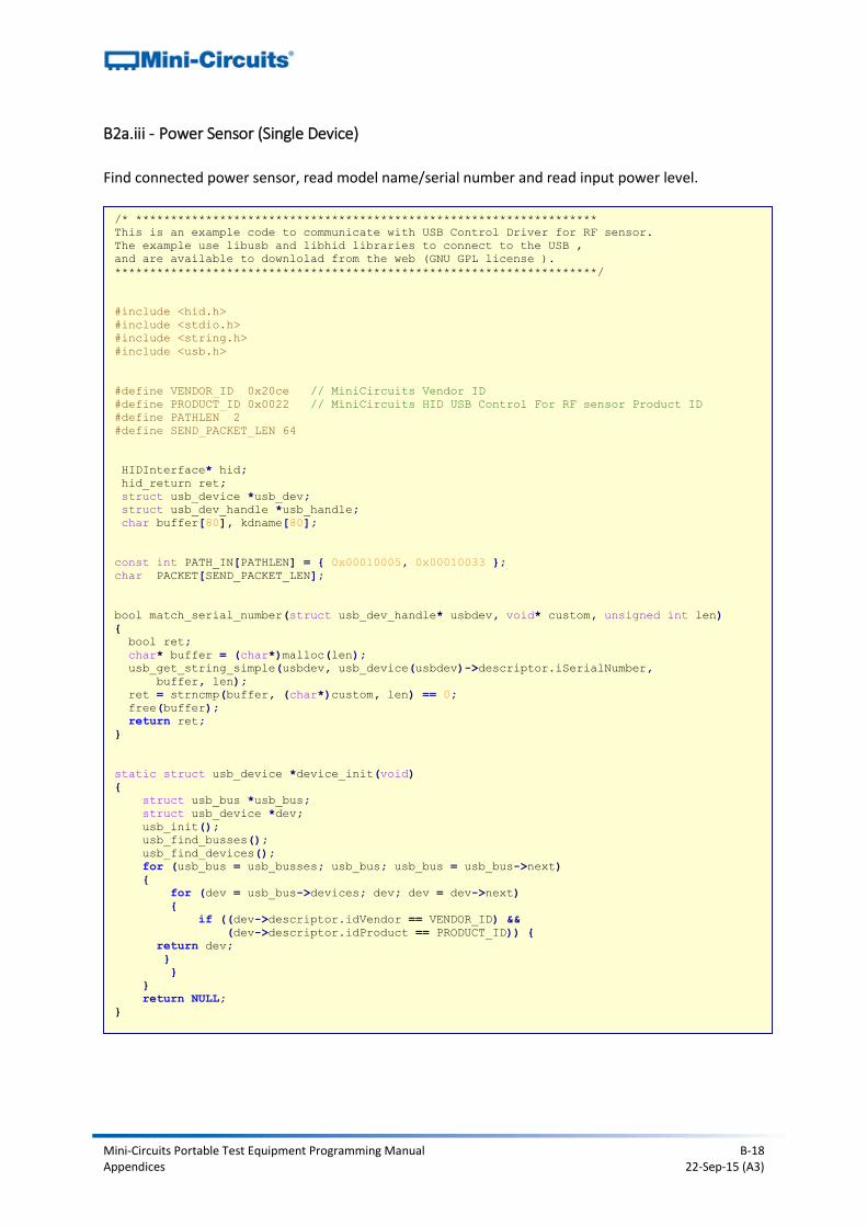
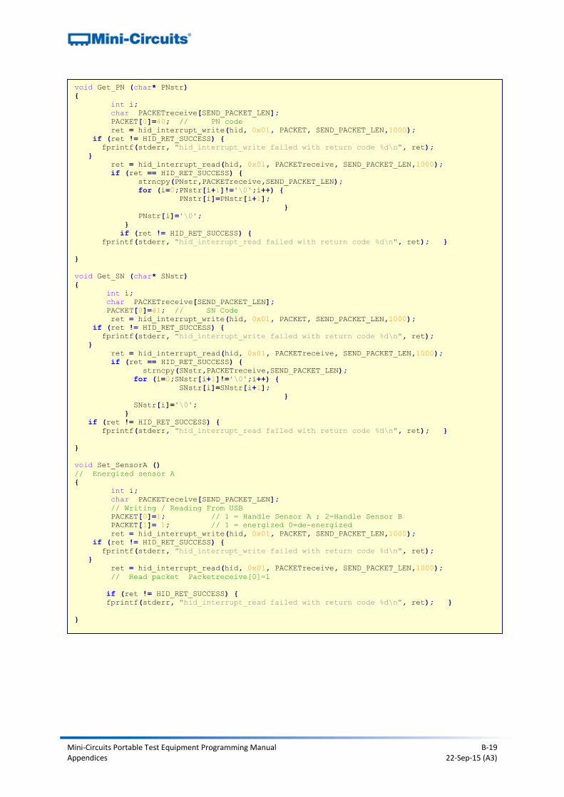
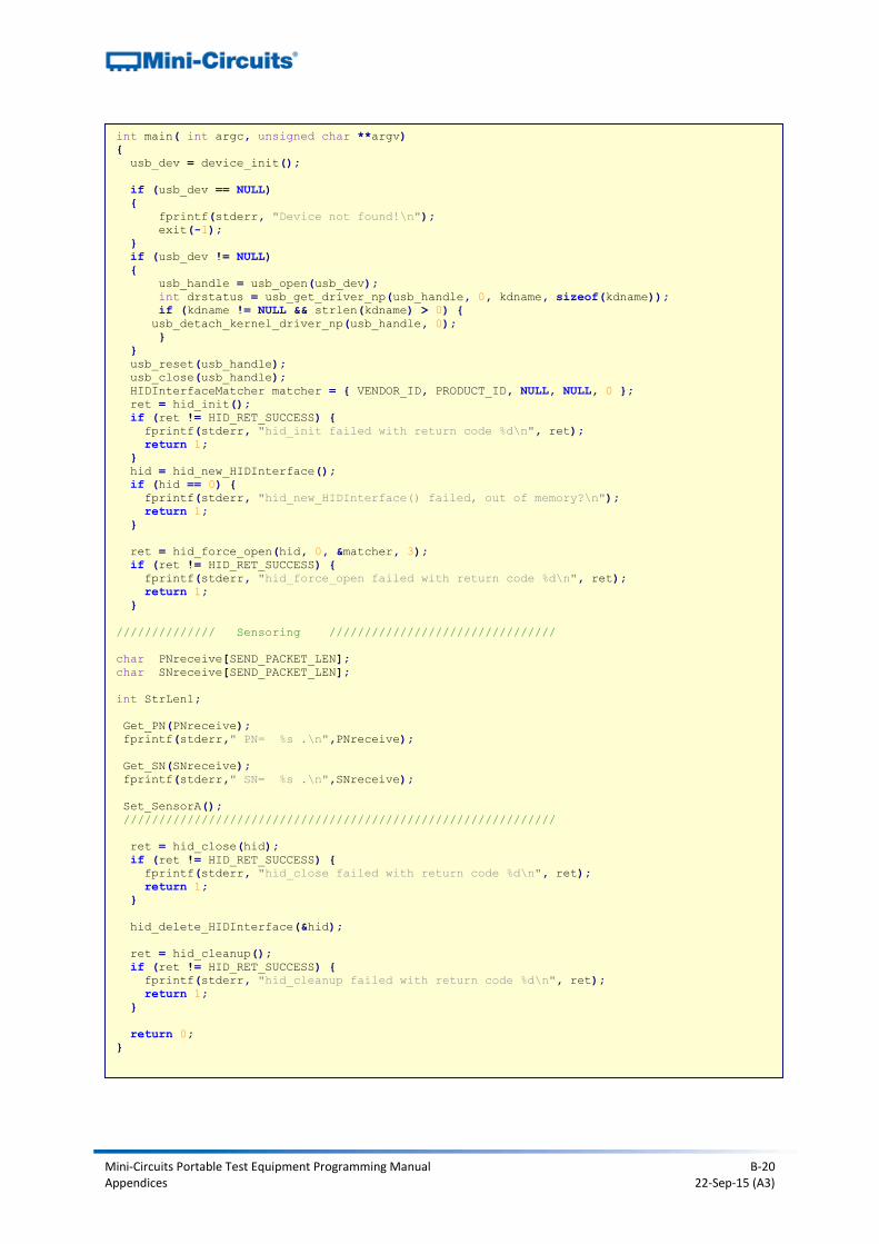
B2a.iii - Power Sensor (Single Device)
Find connected power sensor, read model name/serial number and read input power level.
/* ******************************************************************
This is an example code to communicate with USB Control Driver for RF sensor.
The example use libusb and libhid libraries to connect to the USB ,
and are available to downlolad from the web (GNU GPL license ).
*********************************************************************/
#include <hid.h>
#include <stdio.h>
#include <string.h>
#include <usb.h>
#define VENDOR_ID 0x20ce // MiniCircuits Vendor ID
#define PRODUCT_ID 0x0022 // MiniCircuits HID USB Control For RF sensor Product ID
#define PATHLEN 2
#define SEND_PACKET_LEN 64
HIDInterface* hid;
hid_return ret;
struct usb_device *usb_dev;
struct usb_dev_handle *usb_handle;
char buffer[80], kdname[80];
const int PATH_IN[PATHLEN] = { 0x00010005, 0x00010033 };
char PACKET[SEND_PACKET_LEN];
bool match_serial_number(struct usb_dev_handle* usbdev, void* custom, unsigned int len)
{
bool ret;
char* buffer = (char*)malloc(len);
usb_get_string_simple(usbdev, usb_device(usbdev)->descriptor.iSerialNumber,
buffer, len);
ret = strncmp(buffer, (char*)custom, len) == 0;
free(buffer);
return ret;
}
static struct usb_device *device_init(void)
{
struct usb_bus *usb_bus;
struct usb_device *dev;
usb_init();
usb_find_busses();
usb_find_devices();
for (usb_bus = usb_busses; usb_bus; usb_bus = usb_bus->next)
{
for (dev = usb_bus->devices; dev; dev = dev->next)
{
if ((dev->descriptor.idVendor == VENDOR_ID) &&
(dev->descriptor.idProduct == PRODUCT_ID)) {
return dev;
}
}
}
return NULL;
}
Mini-Circuits Portable Test Equipment Programming Manual B-19 Appendices 22-Sep-15 (A3)
void Get_PN (char* PNstr)
{
int i;
char PACKETreceive[SEND_PACKET_LEN];
PACKET[0]=40; // PN code
ret = hid_interrupt_write(hid, 0x01, PACKET, SEND_PACKET_LEN,1000);
if (ret != HID_RET_SUCCESS) {
fprintf(stderr, "hid_interrupt_write failed with return code %d\n", ret);
}
ret = hid_interrupt_read(hid, 0x01, PACKETreceive, SEND_PACKET_LEN,1000);
if (ret == HID_RET_SUCCESS) {
strncpy(PNstr,PACKETreceive,SEND_PACKET_LEN);
for (i=0;PNstr[i+1]!='\0';i++) {
PNstr[i]=PNstr[i+1];
}
PNstr[i]='\0';
}
if (ret != HID_RET_SUCCESS) {
fprintf(stderr, "hid_interrupt_read failed with return code %d\n", ret); }
}
void Get_SN (char* SNstr)
{
int i;
char PACKETreceive[SEND_PACKET_LEN];
PACKET[0]=41; // SN Code
ret = hid_interrupt_write(hid, 0x01, PACKET, SEND_PACKET_LEN,1000);
if (ret != HID_RET_SUCCESS) {
fprintf(stderr, "hid_interrupt_write failed with return code %d\n", ret);
}
ret = hid_interrupt_read(hid, 0x01, PACKETreceive, SEND_PACKET_LEN,1000);
if (ret == HID_RET_SUCCESS) {
strncpy(SNstr,PACKETreceive,SEND_PACKET_LEN);
for (i=0;SNstr[i+1]!='\0';i++) {
SNstr[i]=SNstr[i+1];
}
SNstr[i]='\0';
}
if (ret != HID_RET_SUCCESS) {
fprintf(stderr, "hid_interrupt_read failed with return code %d\n", ret); }
}
void Set_SensorA ()
// Energized sensor A
{
int i;
char PACKETreceive[SEND_PACKET_LEN];
// Writing / Reading From USB
PACKET[0]=1; // 1 = Handle Sensor A ; 2=Handle Sensor B
PACKET[1]= 1; // 1 = energized 0=de-energized
ret = hid_interrupt_write(hid, 0x01, PACKET, SEND_PACKET_LEN,1000);
if (ret != HID_RET_SUCCESS) {
fprintf(stderr, "hid_interrupt_write failed with return code %d\n", ret);
}
ret = hid_interrupt_read(hid, 0x01, PACKETreceive, SEND_PACKET_LEN,1000);
// Read packet Packetreceive[0]=1
if (ret != HID_RET_SUCCESS) {
fprintf(stderr, "hid_interrupt_read failed with return code %d\n", ret); }
}
Mini-Circuits Portable Test Equipment Programming Manual B-20 Appendices 22-Sep-15 (A3)
int main( int argc, unsigned char **argv)
{
usb_dev = device_init();
if (usb_dev == NULL)
{
fprintf(stderr, "Device not found!\n");
exit(-1);
}
if (usb_dev != NULL)
{
usb_handle = usb_open(usb_dev);
int drstatus = usb_get_driver_np(usb_handle, 0, kdname, sizeof(kdname));
if (kdname != NULL && strlen(kdname) > 0) {
usb_detach_kernel_driver_np(usb_handle, 0);
}
}
usb_reset(usb_handle);
usb_close(usb_handle);
HIDInterfaceMatcher matcher = { VENDOR_ID, PRODUCT_ID, NULL, NULL, 0 };
ret = hid_init();
if (ret != HID_RET_SUCCESS) {
fprintf(stderr, "hid_init failed with return code %d\n", ret);
return 1;
}
hid = hid_new_HIDInterface();
if (hid == 0) {
fprintf(stderr, "hid_new_HIDInterface() failed, out of memory?\n");
return 1;
}
ret = hid_force_open(hid, 0, &matcher, 3);
if (ret != HID_RET_SUCCESS) {
fprintf(stderr, "hid_force_open failed with return code %d\n", ret);
return 1;
}
////////////// Sensoring ////////////////////////////////
char PNreceive[SEND_PACKET_LEN];
char SNreceive[SEND_PACKET_LEN];
int StrLen1;
Get_PN(PNreceive);
fprintf(stderr," PN= %s .\n",PNreceive);
Get_SN(SNreceive);
fprintf(stderr," SN= %s .\n",SNreceive);
Set_SensorA();
/////////////////////////////////////////////////////////////
ret = hid_close(hid);
if (ret != HID_RET_SUCCESS) {
fprintf(stderr, "hid_close failed with return code %d\n", ret);
return 1;
}
hid_delete_HIDInterface(&hid);
ret = hid_cleanup();
if (ret != HID_RET_SUCCESS) {
fprintf(stderr, "hid_cleanup failed with return code %d\n", ret);
return 1;
}
return 0;
}
Mini-Circuits Portable Test Equipment Programming Manual B-21 Appendices 22-Sep-15 (A3)
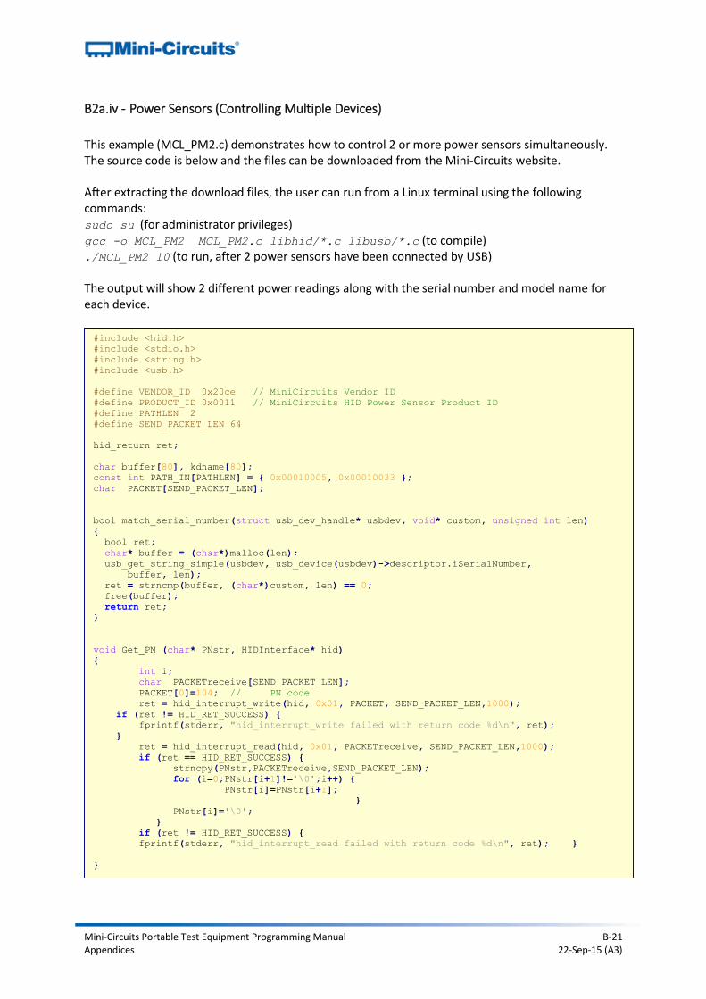
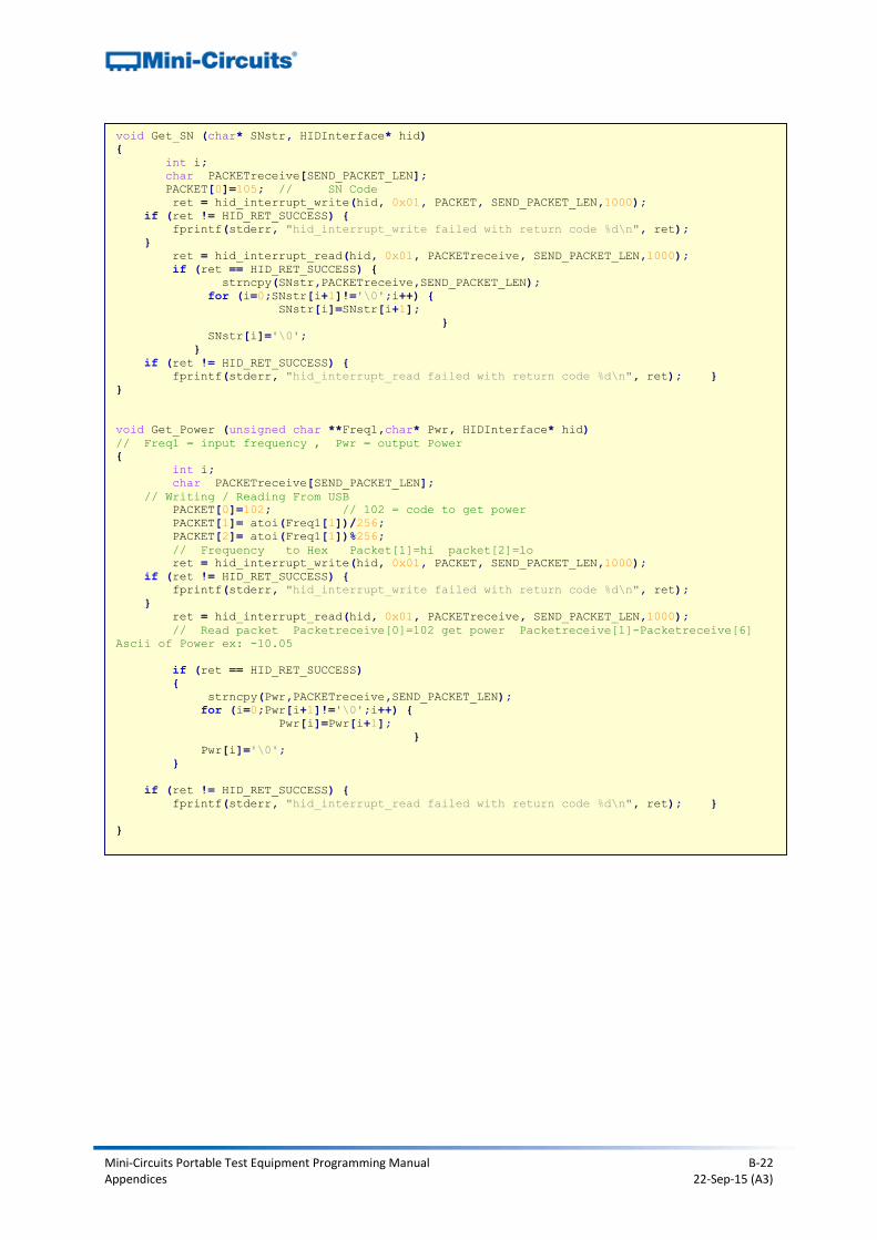
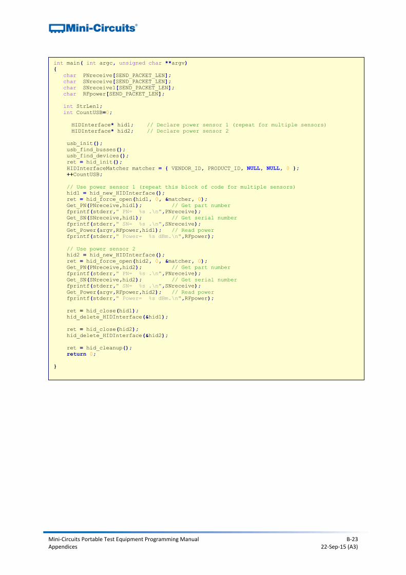
B2a.iv - Power Sensors (Controlling Multiple Devices)
This example (MCL_PM2.c) demonstrates how to control 2 or more power sensors simultaneously. The source code is below and the files can be downloaded from the Mini-Circuits website. After extracting the download files, the user can run from a Linux terminal using the following commands: sudo su (for administrator privileges) gcc -o MCL_PM2 MCL_PM2.c libhid/*.c libusb/*.c (to compile) ./MCL_PM2 10 (to run, after 2 power sensors have been connected by USB) The output will show 2 different power readings along with the serial number and model name for each device.
#include <hid.h>
#include <stdio.h>
#include <string.h>
#include <usb.h>
#define VENDOR_ID 0x20ce // MiniCircuits Vendor ID
#define PRODUCT_ID 0x0011 // MiniCircuits HID Power Sensor Product ID
#define PATHLEN 2
#define SEND_PACKET_LEN 64
hid_return ret;
char buffer[80], kdname[80];
const int PATH_IN[PATHLEN] = { 0x00010005, 0x00010033 };
char PACKET[SEND_PACKET_LEN];
bool match_serial_number(struct usb_dev_handle* usbdev, void* custom, unsigned int len)
{
bool ret;
char* buffer = (char*)malloc(len);
usb_get_string_simple(usbdev, usb_device(usbdev)->descriptor.iSerialNumber,
buffer, len);
ret = strncmp(buffer, (char*)custom, len) == 0;
free(buffer);
return ret;
}
void Get_PN (char* PNstr, HIDInterface* hid)
{
int i;
char PACKETreceive[SEND_PACKET_LEN];
PACKET[0]=104; // PN code
ret = hid_interrupt_write(hid, 0x01, PACKET, SEND_PACKET_LEN,1000);
if (ret != HID_RET_SUCCESS) {
fprintf(stderr, "hid_interrupt_write failed with return code %d\n", ret);
}
ret = hid_interrupt_read(hid, 0x01, PACKETreceive, SEND_PACKET_LEN,1000);
if (ret == HID_RET_SUCCESS) {
strncpy(PNstr,PACKETreceive,SEND_PACKET_LEN);
for (i=0;PNstr[i+1]!='\0';i++) {
PNstr[i]=PNstr[i+1];
}
PNstr[i]='\0';
}
if (ret != HID_RET_SUCCESS) {
fprintf(stderr, "hid_interrupt_read failed with return code %d\n", ret); }
}
Mini-Circuits Portable Test Equipment Programming Manual B-22 Appendices 22-Sep-15 (A3)
void Get_SN (char* SNstr, HIDInterface* hid)
{
int i;
char PACKETreceive[SEND_PACKET_LEN];
PACKET[0]=105; // SN Code
ret = hid_interrupt_write(hid, 0x01, PACKET, SEND_PACKET_LEN,1000);
if (ret != HID_RET_SUCCESS) {
fprintf(stderr, "hid_interrupt_write failed with return code %d\n", ret);
}
ret = hid_interrupt_read(hid, 0x01, PACKETreceive, SEND_PACKET_LEN,1000);
if (ret == HID_RET_SUCCESS) {
strncpy(SNstr,PACKETreceive,SEND_PACKET_LEN);
for (i=0;SNstr[i+1]!='\0';i++) {
SNstr[i]=SNstr[i+1];
}
SNstr[i]='\0';
}
if (ret != HID_RET_SUCCESS) {
fprintf(stderr, "hid_interrupt_read failed with return code %d\n", ret); }
}
void Get_Power (unsigned char **Freq1,char* Pwr, HIDInterface* hid)
// Freq1 = input frequency , Pwr = output Power
{
int i;
char PACKETreceive[SEND_PACKET_LEN];
// Writing / Reading From USB
PACKET[0]=102; // 102 = code to get power
PACKET[1]= atoi(Freq1[1])/256;
PACKET[2]= atoi(Freq1[1])%256;
// Frequency to Hex Packet[1]=hi packet[2]=lo
ret = hid_interrupt_write(hid, 0x01, PACKET, SEND_PACKET_LEN,1000);
if (ret != HID_RET_SUCCESS) {
fprintf(stderr, "hid_interrupt_write failed with return code %d\n", ret);
}
ret = hid_interrupt_read(hid, 0x01, PACKETreceive, SEND_PACKET_LEN,1000);
// Read packet Packetreceive[0]=102 get power Packetreceive[1]-Packetreceive[6]
Ascii of Power ex: -10.05
if (ret == HID_RET_SUCCESS)
{
strncpy(Pwr,PACKETreceive,SEND_PACKET_LEN);
for (i=0;Pwr[i+1]!='\0';i++) {
Pwr[i]=Pwr[i+1];
}
Pwr[i]='\0';
}
if (ret != HID_RET_SUCCESS) {
fprintf(stderr, "hid_interrupt_read failed with return code %d\n", ret); }
}
Mini-Circuits Portable Test Equipment Programming Manual B-23 Appendices 22-Sep-15 (A3)
int main( int argc, unsigned char **argv)
{
char PNreceive[SEND_PACKET_LEN];
char SNreceive[SEND_PACKET_LEN];
char SNreceive1[SEND_PACKET_LEN];
char RFpower[SEND_PACKET_LEN];
int StrLen1;
int CountUSB=0;
HIDInterface* hid1; // Declare power sensor 1 (repeat for multiple sensors)
HIDInterface* hid2; // Declare power sensor 2
usb_init();
usb_find_busses();
usb_find_devices();
ret = hid_init();
HIDInterfaceMatcher matcher = { VENDOR_ID, PRODUCT_ID, NULL, NULL, 0 };
++CountUSB;
// Use power sensor 1 (repeat this block of code for multiple sensors)
hid1 = hid_new_HIDInterface();
ret = hid_force_open(hid1, 0, &matcher, 0);
Get_PN(PNreceive,hid1); // Get part number
fprintf(stderr," PN= %s .\n",PNreceive);
Get_SN(SNreceive,hid1); // Get serial number
fprintf(stderr," SN= %s .\n",SNreceive);
Get_Power(argv,RFpower,hid1); // Read power
fprintf(stderr," Power= %s dBm.\n",RFpower);
// Use power sensor 2
hid2 = hid_new_HIDInterface();
ret = hid_force_open(hid2, 0, &matcher, 0);
Get_PN(PNreceive,hid2); // Get part number
fprintf(stderr," PN= %s .\n",PNreceive);
Get_SN(SNreceive,hid2); // Get serial number
fprintf(stderr," SN= %s .\n",SNreceive);
Get_Power(argv,RFpower,hid2); // Read power
fprintf(stderr," Power= %s dBm.\n",RFpower);
ret = hid_close(hid1);
hid_delete_HIDInterface(&hid1);
ret = hid_close(hid2);
hid_delete_HIDInterface(&hid2);
ret = hid_cleanup();
return 0;
}
Mini-Circuits Portable Test Equipment Programming Manual B-24 Appendices 22-Sep-15 (A3)
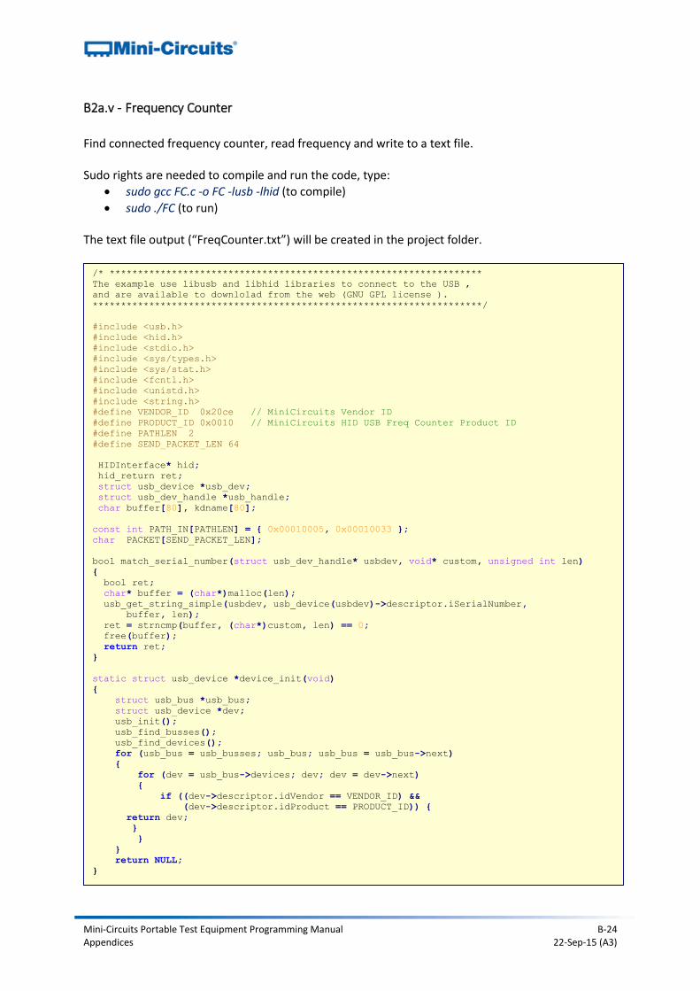
B2a.v - Frequency Counter
Find connected frequency counter, read frequency and write to a text file. Sudo rights are needed to compile and run the code, type:
sudo gcc FC.c -o FC -lusb -lhid (to compile)
sudo ./FC (to run) The text file output (“FreqCounter.txt”) will be created in the project folder.
/* ******************************************************************
The example use libusb and libhid libraries to connect to the USB ,
and are available to downlolad from the web (GNU GPL license ).
*********************************************************************/
#include <usb.h>
#include <hid.h>
#include <stdio.h>
#include <sys/types.h>
#include <sys/stat.h>
#include <fcntl.h>
#include <unistd.h>
#include <string.h>
#define VENDOR_ID 0x20ce // MiniCircuits Vendor ID
#define PRODUCT_ID 0x0010 // MiniCircuits HID USB Freq Counter Product ID
#define PATHLEN 2
#define SEND_PACKET_LEN 64
HIDInterface* hid;
hid_return ret;
struct usb_device *usb_dev;
struct usb_dev_handle *usb_handle;
char buffer[80], kdname[80];
const int PATH_IN[PATHLEN] = { 0x00010005, 0x00010033 };
char PACKET[SEND_PACKET_LEN];
bool match_serial_number(struct usb_dev_handle* usbdev, void* custom, unsigned int len)
{
bool ret;
char* buffer = (char*)malloc(len);
usb_get_string_simple(usbdev, usb_device(usbdev)->descriptor.iSerialNumber,
buffer, len);
ret = strncmp(buffer, (char*)custom, len) == 0;
free(buffer);
return ret;
}
static struct usb_device *device_init(void)
{
struct usb_bus *usb_bus;
struct usb_device *dev;
usb_init();
usb_find_busses();
usb_find_devices();
for (usb_bus = usb_busses; usb_bus; usb_bus = usb_bus->next)
{
for (dev = usb_bus->devices; dev; dev = dev->next)
{
if ((dev->descriptor.idVendor == VENDOR_ID) &&
(dev->descriptor.idProduct == PRODUCT_ID)) {
return dev;
}
}
}
return NULL;
}
Mini-Circuits Portable Test Equipment Programming Manual B-25 Appendices 22-Sep-15 (A3)
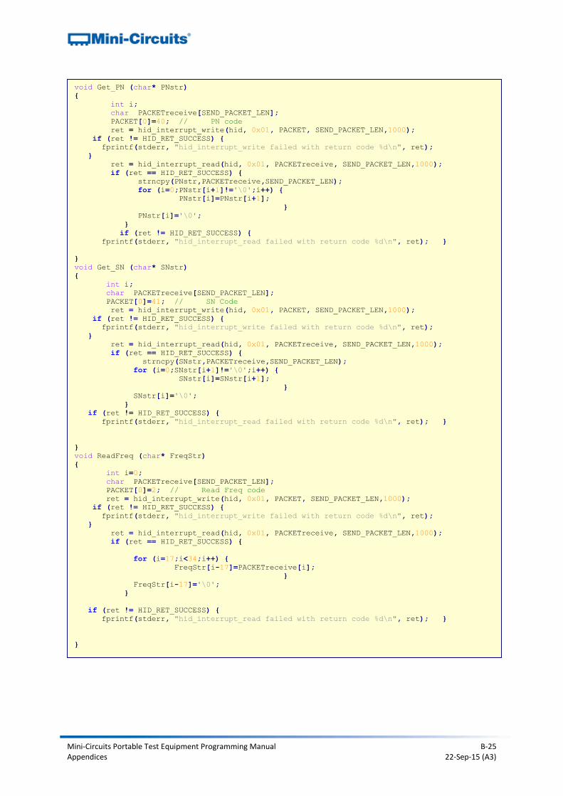
void Get_PN (char* PNstr)
{
int i;
char PACKETreceive[SEND_PACKET_LEN];
PACKET[0]=40; // PN code
ret = hid_interrupt_write(hid, 0x01, PACKET, SEND_PACKET_LEN,1000);
if (ret != HID_RET_SUCCESS) {
fprintf(stderr, "hid_interrupt_write failed with return code %d\n", ret);
}
ret = hid_interrupt_read(hid, 0x01, PACKETreceive, SEND_PACKET_LEN,1000);
if (ret == HID_RET_SUCCESS) {
strncpy(PNstr,PACKETreceive,SEND_PACKET_LEN);
for (i=0;PNstr[i+1]!='\0';i++) {
PNstr[i]=PNstr[i+1];
}
PNstr[i]='\0';
}
if (ret != HID_RET_SUCCESS) {
fprintf(stderr, "hid_interrupt_read failed with return code %d\n", ret); }
}
void Get_SN (char* SNstr)
{
int i;
char PACKETreceive[SEND_PACKET_LEN];
PACKET[0]=41; // SN Code
ret = hid_interrupt_write(hid, 0x01, PACKET, SEND_PACKET_LEN,1000);
if (ret != HID_RET_SUCCESS) {
fprintf(stderr, "hid_interrupt_write failed with return code %d\n", ret);
}
ret = hid_interrupt_read(hid, 0x01, PACKETreceive, SEND_PACKET_LEN,1000);
if (ret == HID_RET_SUCCESS) {
strncpy(SNstr,PACKETreceive,SEND_PACKET_LEN);
for (i=0;SNstr[i+1]!='\0';i++) {
SNstr[i]=SNstr[i+1];
}
SNstr[i]='\0';
}
if (ret != HID_RET_SUCCESS) {
fprintf(stderr, "hid_interrupt_read failed with return code %d\n", ret); }
}
void ReadFreq (char* FreqStr)
{
int i=0;
char PACKETreceive[SEND_PACKET_LEN];
PACKET[0]=2; // Read Freq code
ret = hid_interrupt_write(hid, 0x01, PACKET, SEND_PACKET_LEN,1000);
if (ret != HID_RET_SUCCESS) {
fprintf(stderr, "hid_interrupt_write failed with return code %d\n", ret);
}
ret = hid_interrupt_read(hid, 0x01, PACKETreceive, SEND_PACKET_LEN,1000);
if (ret == HID_RET_SUCCESS) {
for (i=17;i<34;i++) {
FreqStr[i-17]=PACKETreceive[i];
}
FreqStr[i-17]='\0';
}
if (ret != HID_RET_SUCCESS) {
fprintf(stderr, "hid_interrupt_read failed with return code %d\n", ret); }
}
Mini-Circuits Portable Test Equipment Programming Manual B-26 Appendices 22-Sep-15 (A3)
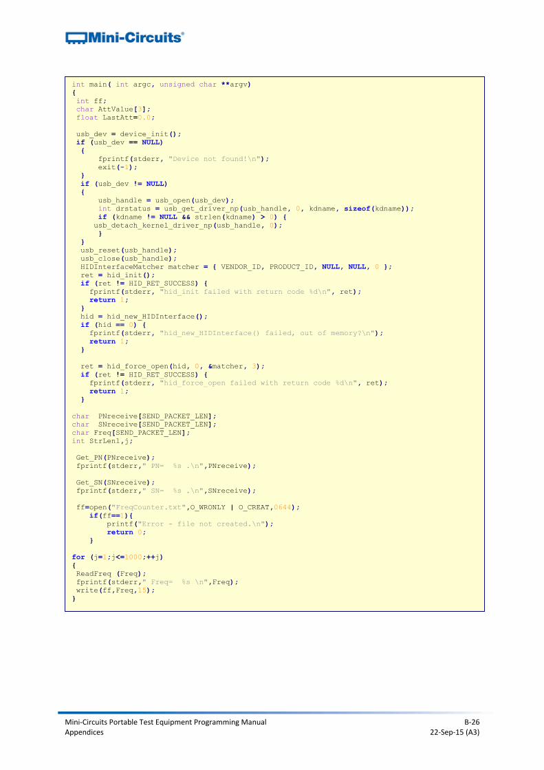
int main( int argc, unsigned char **argv)
{
int ff;
char AttValue[3];
float LastAtt=0.0;
usb_dev = device_init();
if (usb_dev == NULL)
{
fprintf(stderr, "Device not found!\n");
exit(-1);
}
if (usb_dev != NULL)
{
usb_handle = usb_open(usb_dev);
int drstatus = usb_get_driver_np(usb_handle, 0, kdname, sizeof(kdname));
if (kdname != NULL && strlen(kdname) > 0) {
usb_detach_kernel_driver_np(usb_handle, 0);
}
}
usb_reset(usb_handle);
usb_close(usb_handle);
HIDInterfaceMatcher matcher = { VENDOR_ID, PRODUCT_ID, NULL, NULL, 0 };
ret = hid_init();
if (ret != HID_RET_SUCCESS) {
fprintf(stderr, "hid_init failed with return code %d\n", ret);
return 1;
}
hid = hid_new_HIDInterface();
if (hid == 0) {
fprintf(stderr, "hid_new_HIDInterface() failed, out of memory?\n");
return 1;
}
ret = hid_force_open(hid, 0, &matcher, 3);
if (ret != HID_RET_SUCCESS) {
fprintf(stderr, "hid_force_open failed with return code %d\n", ret);
return 1;
}
char PNreceive[SEND_PACKET_LEN];
char SNreceive[SEND_PACKET_LEN];
char Freq[SEND_PACKET_LEN];
int StrLen1,j;
Get_PN(PNreceive);
fprintf(stderr," PN= %s .\n",PNreceive);
Get_SN(SNreceive);
fprintf(stderr," SN= %s .\n",SNreceive);
ff=open("FreqCounter.txt",O_WRONLY | O_CREAT,0644);
if(ff==1){
printf("Error - file not created.\n");
return 0;
}
for (j=1;j<=1000;++j)
{
ReadFreq (Freq);
fprintf(stderr," Freq= %s \n",Freq);
write(ff,Freq,15);
}
Mini-Circuits Portable Test Equipment Programming Manual B-27 Appendices 22-Sep-15 (A3)
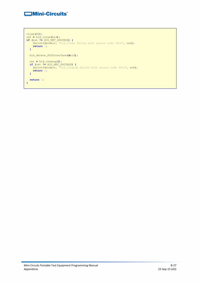
close(ff);
ret = hid_close(hid);
if (ret != HID_RET_SUCCESS) {
fprintf(stderr, "hid_close failed with return code %d\n", ret);
return 1;
}
hid_delete_HIDInterface(&hid);
ret = hid_cleanup();
if (ret != HID_RET_SUCCESS) {
fprintf(stderr, "hid_cleanup failed with return code %d\n", ret);
return 1;
}
return 0;
}
Mini-Circuits Portable Test Equipment Programming Manual B-28 Appendices 22-Sep-15 (A3)
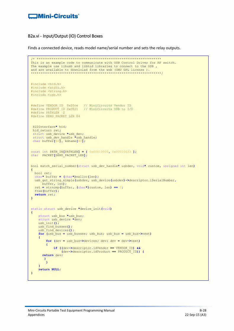
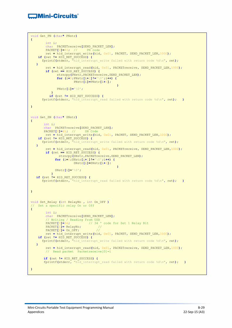
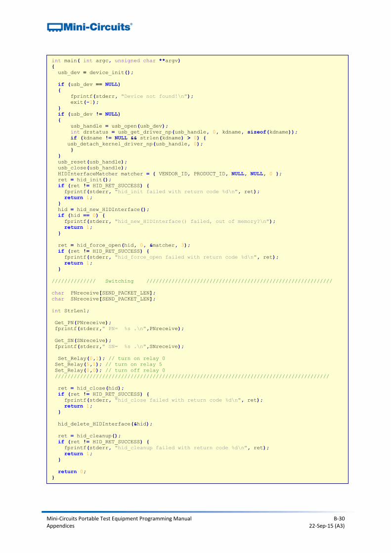
B2a.vi - Input/Output (IO) Control Boxes
Finds a connected device, reads model name/serial number and sets the relay outputs.
/* ******************************************************************
This is an example code to communicate with USB Control Driver for RF switch.
The example use libusb and libhid libraries to connect to the USB ,
and are available to downlolad from the web (GNU GPL license ).
*********************************************************************/
#include <hid.h>
#include <stdio.h>
#include <string.h>
#include <usb.h>
#define VENDOR_ID 0x20ce // MiniCircuits Vendor ID
#define PRODUCT_ID 0x0021 // MiniCircuits USB to I/O
#define PATHLEN 2
#define SEND_PACKET_LEN 64
HIDInterface* hid;
hid_return ret;
struct usb_device *usb_dev;
struct usb_dev_handle *usb_handle;
char buffer[80], kdname[80];
const int PATH_IN[PATHLEN] = { 0x00010005, 0x00010033 };
char PACKET[SEND_PACKET_LEN];
bool match_serial_number(struct usb_dev_handle* usbdev, void* custom, unsigned int len)
{
bool ret;
char* buffer = (char*)malloc(len);
usb_get_string_simple(usbdev, usb_device(usbdev)->descriptor.iSerialNumber,
buffer, len);
ret = strncmp(buffer, (char*)custom, len) == 0;
free(buffer);
return ret;
}
static struct usb_device *device_init(void)
{
struct usb_bus *usb_bus;
struct usb_device *dev;
usb_init();
usb_find_busses();
usb_find_devices();
for (usb_bus = usb_busses; usb_bus; usb_bus = usb_bus->next)
{
for (dev = usb_bus->devices; dev; dev = dev->next)
{
if ((dev->descriptor.idVendor == VENDOR_ID) &&
(dev->descriptor.idProduct == PRODUCT_ID)) {
return dev;
}
}
}
return NULL;
}
Mini-Circuits Portable Test Equipment Programming Manual B-29 Appendices 22-Sep-15 (A3)
void Get_PN (char* PNstr)
{
int i;
char PACKETreceive[SEND_PACKET_LEN];
PACKET[0]=40; // PN code
ret = hid_interrupt_write(hid, 0x01, PACKET, SEND_PACKET_LEN,1000);
if (ret != HID_RET_SUCCESS) {
fprintf(stderr, "hid_interrupt_write failed with return code %d\n", ret);
}
ret = hid_interrupt_read(hid, 0x01, PACKETreceive, SEND_PACKET_LEN,1000);
if (ret == HID_RET_SUCCESS) {
strncpy(PNstr,PACKETreceive,SEND_PACKET_LEN);
for (i=0;PNstr[i+1]!='\0';i++) {
PNstr[i]=PNstr[i+1];
}
PNstr[i]='\0';
}
if (ret != HID_RET_SUCCESS) {
fprintf(stderr, "hid_interrupt_read failed with return code %d\n", ret); }
}
void Get_SN (char* SNstr)
{
int i;
char PACKETreceive[SEND_PACKET_LEN];
PACKET[0]=41; // SN Code
ret = hid_interrupt_write(hid, 0x01, PACKET, SEND_PACKET_LEN,1000);
if (ret != HID_RET_SUCCESS) {
fprintf(stderr, "hid_interrupt_write failed with return code %d\n", ret);
}
ret = hid_interrupt_read(hid, 0x01, PACKETreceive, SEND_PACKET_LEN,1000);
if (ret == HID_RET_SUCCESS) {
strncpy(SNstr,PACKETreceive,SEND_PACKET_LEN);
for (i=0;SNstr[i+1]!='\0';i++) {
SNstr[i]=SNstr[i+1];
}
SNstr[i]='\0';
}
if (ret != HID_RET_SUCCESS) {
fprintf(stderr, "hid_interrupt_read failed with return code %d\n", ret); }
}
void Set_Relay (int RelayNo , int On_OFF )
// Set a specific relay On or Off
{
int i;
char PACKETreceive[SEND_PACKET_LEN];
// Writing / Reading From USB
PACKET[0]=34; // 34 ' code for Set 1 Relay Bit
PACKET[1]= RelayNo; //
PACKET[2]= On_OFF; //
ret = hid_interrupt_write(hid, 0x01, PACKET, SEND_PACKET_LEN,1000);
if (ret != HID_RET_SUCCESS) {
fprintf(stderr, "hid_interrupt_write failed with return code %d\n", ret);
}
ret = hid_interrupt_read(hid, 0x01, PACKETreceive, SEND_PACKET_LEN,1000);
// Read packet Packetreceive[0]=1
if (ret != HID_RET_SUCCESS) {
fprintf(stderr, "hid_interrupt_read failed with return code %d\n", ret); }
}
Mini-Circuits Portable Test Equipment Programming Manual B-30 Appendices 22-Sep-15 (A3)
int main( int argc, unsigned char **argv)
{
usb_dev = device_init();
if (usb_dev == NULL)
{
fprintf(stderr, "Device not found!\n");
exit(-1);
}
if (usb_dev != NULL)
{
usb_handle = usb_open(usb_dev);
int drstatus = usb_get_driver_np(usb_handle, 0, kdname, sizeof(kdname));
if (kdname != NULL && strlen(kdname) > 0) {
usb_detach_kernel_driver_np(usb_handle, 0);
}
}
usb_reset(usb_handle);
usb_close(usb_handle);
HIDInterfaceMatcher matcher = { VENDOR_ID, PRODUCT_ID, NULL, NULL, 0 };
ret = hid_init();
if (ret != HID_RET_SUCCESS) {
fprintf(stderr, "hid_init failed with return code %d\n", ret);
return 1;
}
hid = hid_new_HIDInterface();
if (hid == 0) {
fprintf(stderr, "hid_new_HIDInterface() failed, out of memory?\n");
return 1;
}
ret = hid_force_open(hid, 0, &matcher, 3);
if (ret != HID_RET_SUCCESS) {
fprintf(stderr, "hid_force_open failed with return code %d\n", ret);
return 1;
}
////////////// Switching ///////////////////////////////////////////////////////////
char PNreceive[SEND_PACKET_LEN];
char SNreceive[SEND_PACKET_LEN];
int StrLen1;
Get_PN(PNreceive);
fprintf(stderr," PN= %s .\n",PNreceive);
Get_SN(SNreceive);
fprintf(stderr," SN= %s .\n",SNreceive);
Set_Relay(0,1); // turn on relay 0
Set_Relay(5,1); // turn on relay 5
Set_Relay(0,0); // turn off relay 0
///////////////////////////////////////////////////////////////////////////////////////
ret = hid_close(hid);
if (ret != HID_RET_SUCCESS) {
fprintf(stderr, "hid_close failed with return code %d\n", ret);
return 1;
}
hid_delete_HIDInterface(&hid);
ret = hid_cleanup();
if (ret != HID_RET_SUCCESS) {
fprintf(stderr, "hid_cleanup failed with return code %d\n", ret);
return 1;
}
return 0;
}
Mini-Circuits Portable Test Equipment Programming Manual B-31 Appendices 22-Sep-15 (A3)
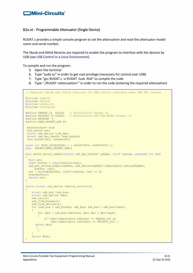
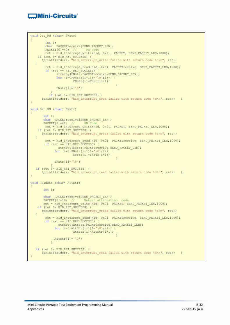
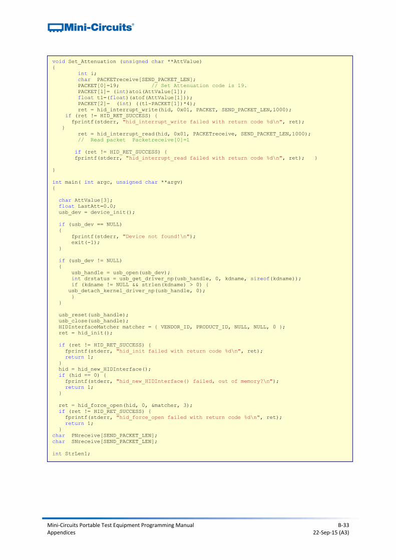
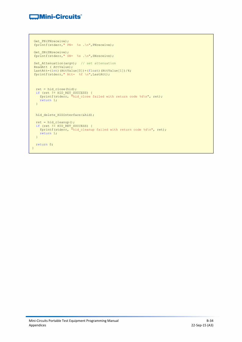
B2a.vii - Programmable Attenuator (Single Device)
RUDAT.c provides a simple console program to set the attenuation and read the attenuator model name and serial number. The libusb and libhid libraries are required to enable the program to interface with the devices by USB (see USB Control in a Linux Environment). To compile and run the program:
5. Open the terminal 6. Type “sudo su” in order to get root privilege (necessary for control over USB) 7. Type “gcc RUDAT.c -o RUDAT -lusb -lhid” to compile the code 8. Type “./RUDAT <attenuation>” in order to run the code (entering the required attenuation)
// Requires libusb and libhid libraries for USB control available under GNU GPL license
#include <usb.h>
#include <hid.h>
#include <stdio.h>
#include <string.h>
#define VENDOR_ID 0x20ce // MiniCircuits Vendor ID
#define PRODUCT_ID 0x0023 // MiniCircuits HID USB RUDAT Product ID
#define PATHLEN 2
#define SEND_PACKET_LEN 64
HIDInterface* hid;
hid_return ret;
struct usb_device *usb_dev;
struct usb_dev_handle *usb_handle;
char buffer[80], kdname[80];
const int PATH_IN[PATHLEN] = { 0x00010005, 0x00010033 };
char PACKET[SEND_PACKET_LEN];
bool match_serial_number(struct usb_dev_handle* usbdev, void* custom, unsigned int len)
{
bool ret;
char* buffer = (char*)malloc(len);
usb_get_string_simple(usbdev, usb_device(usbdev)->descriptor.iSerialNumber,
buffer, len);
ret = strncmp(buffer, (char*)custom, len) == 0;
free(buffer);
return ret;
}
static struct usb_device *device_init(void)
{
struct usb_bus *usb_bus;
struct usb_device *dev;
usb_init();
usb_find_busses();
usb_find_devices();
for (usb_bus = usb_busses; usb_bus; usb_bus = usb_bus->next)
{
for (dev = usb_bus->devices; dev; dev = dev->next)
{
if ((dev->descriptor.idVendor == VENDOR_ID) &&
(dev->descriptor.idProduct == PRODUCT_ID)) {
return dev;
}
}
}
return NULL;
}
Mini-Circuits Portable Test Equipment Programming Manual B-32 Appendices 22-Sep-15 (A3)
void Get_PN (char* PNstr)
{
int i;
char PACKETreceive[SEND_PACKET_LEN];
PACKET[0]=40; // PN code
ret = hid_interrupt_write(hid, 0x01, PACKET, SEND_PACKET_LEN,1000);
if (ret != HID_RET_SUCCESS) {
fprintf(stderr, "hid_interrupt_write failed with return code %d\n", ret);
}
ret = hid_interrupt_read(hid, 0x01, PACKETreceive, SEND_PACKET_LEN,1000);
if (ret == HID_RET_SUCCESS) {
strncpy(PNstr,PACKETreceive,SEND_PACKET_LEN);
for (i=0;PNstr[i+1]!='\0';i++) {
PNstr[i]=PNstr[i+1];
}
PNstr[i]='\0';
}
if (ret != HID_RET_SUCCESS) {
fprintf(stderr, "hid_interrupt_read failed with return code %d\n", ret); }
}
void Get_SN (char* SNstr)
{
int i;
char PACKETreceive[SEND_PACKET_LEN];
PACKET[0]=41; // SN Code
ret = hid_interrupt_write(hid, 0x01, PACKET, SEND_PACKET_LEN,1000);
if (ret != HID_RET_SUCCESS) {
fprintf(stderr, "hid_interrupt_write failed with return code %d\n", ret);
}
ret = hid_interrupt_read(hid, 0x01, PACKETreceive, SEND_PACKET_LEN,1000);
if (ret == HID_RET_SUCCESS) {
strncpy(SNstr,PACKETreceive,SEND_PACKET_LEN);
for (i=0;SNstr[i+1]!='\0';i++) {
SNstr[i]=SNstr[i+1];
}
SNstr[i]='\0';
}
if (ret != HID_RET_SUCCESS) {
fprintf(stderr, "hid_interrupt_read failed with return code %d\n", ret); }
}
void ReadAtt (char* AttStr)
{
int i;
char PACKETreceive[SEND_PACKET_LEN];
PACKET[0]=18; // Ruturn attenuation code
ret = hid_interrupt_write(hid, 0x01, PACKET, SEND_PACKET_LEN,1000);
if (ret != HID_RET_SUCCESS) {
fprintf(stderr, "hid_interrupt_write failed with return code %d\n", ret);
}
ret = hid_interrupt_read(hid, 0x01, PACKETreceive, SEND_PACKET_LEN,1000);
if (ret == HID_RET_SUCCESS) {
strncpy(AttStr,PACKETreceive,SEND_PACKET_LEN);
for (i=0;AttStr[i+1]!='\0';i++) {
AttStr[i]=AttStr[i+1];
}
AttStr[i]='\0';
}
if (ret != HID_RET_SUCCESS) {
fprintf(stderr, "hid_interrupt_read failed with return code %d\n", ret); }
}
Mini-Circuits Portable Test Equipment Programming Manual B-33 Appendices 22-Sep-15 (A3)
void Set_Attenuation (unsigned char **AttValue)
{
int i;
char PACKETreceive[SEND_PACKET_LEN];
PACKET[0]=19; // Set Attenuation code is 19.
PACKET[1]= (int)atoi(AttValue[1]);
float t1=(float)(atof(AttValue[1]));
PACKET[2]= (int) ((t1-PACKET[1])*4);
ret = hid_interrupt_write(hid, 0x01, PACKET, SEND_PACKET_LEN,1000);
if (ret != HID_RET_SUCCESS) {
fprintf(stderr, "hid_interrupt_write failed with return code %d\n", ret);
}
ret = hid_interrupt_read(hid, 0x01, PACKETreceive, SEND_PACKET_LEN,1000);
// Read packet Packetreceive[0]=1
if (ret != HID_RET_SUCCESS) {
fprintf(stderr, "hid_interrupt_read failed with return code %d\n", ret); }
}
int main( int argc, unsigned char **argv)
{
char AttValue[3];
float LastAtt=0.0;
usb_dev = device_init();
if (usb_dev == NULL)
{
fprintf(stderr, "Device not found!\n");
exit(-1);
}
if (usb_dev != NULL)
{
usb_handle = usb_open(usb_dev);
int drstatus = usb_get_driver_np(usb_handle, 0, kdname, sizeof(kdname));
if (kdname != NULL && strlen(kdname) > 0) {
usb_detach_kernel_driver_np(usb_handle, 0);
}
}
usb_reset(usb_handle);
usb_close(usb_handle);
HIDInterfaceMatcher matcher = { VENDOR_ID, PRODUCT_ID, NULL, NULL, 0 };
ret = hid_init();
if (ret != HID_RET_SUCCESS) {
fprintf(stderr, "hid_init failed with return code %d\n", ret);
return 1;
}
hid = hid_new_HIDInterface();
if (hid == 0) {
fprintf(stderr, "hid_new_HIDInterface() failed, out of memory?\n");
return 1;
}
ret = hid_force_open(hid, 0, &matcher, 3);
if (ret != HID_RET_SUCCESS) {
fprintf(stderr, "hid_force_open failed with return code %d\n", ret);
return 1;
}
char PNreceive[SEND_PACKET_LEN];
char SNreceive[SEND_PACKET_LEN];
int StrLen1;
Mini-Circuits Portable Test Equipment Programming Manual B-34 Appendices 22-Sep-15 (A3)
Get_PN(PNreceive);
fprintf(stderr," PN= %s .\n",PNreceive);
Get_SN(SNreceive);
fprintf(stderr," SN= %s .\n",SNreceive);
Set_Attenuation(argv); // set attenuation
ReadAtt ( AttValue);
LastAtt=(int)(AttValue[0])+(float)(AttValue[1])/4;
fprintf(stderr," Att= %f \n",LastAtt);
ret = hid_close(hid);
if (ret != HID_RET_SUCCESS) {
fprintf(stderr, "hid_close failed with return code %d\n", ret);
return 1;
}
hid_delete_HIDInterface(&hid);
ret = hid_cleanup();
if (ret != HID_RET_SUCCESS) {
fprintf(stderr, "hid_cleanup failed with return code %d\n", ret);
return 1;
}
return 0;
}
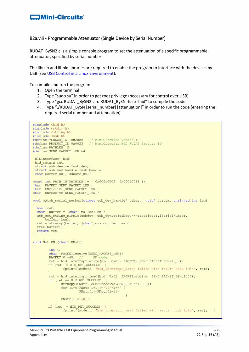
Mini-Circuits Portable Test Equipment Programming Manual B-35 Appendices 22-Sep-15 (A3)
B2a.viii - Programmable Attenuator (Single Device by Serial Number)
RUDAT_BySN2.c is a simple console program to set the attenuation of a specific programmable attenuator, specified by serial number. The libusb and libhid libraries are required to enable the program to interface with the devices by USB (see USB Control in a Linux Environment). To compile and run the program:
1. Open the terminal 2. Type “sudo su” in order to get root privilege (necessary for control over USB) 3. Type “gcc RUDAT_BySN2.c -o RUDAT_BySN -lusb -lhid” to compile the code 4. Type “./RUDAT_BySN [serial_number] [attenuation]” in order to run the code (entering the
required serial number and attenuation)
#include <hid.h>
#include <stdio.h>
#include <string.h>
#include <usb.h>
#define VENDOR_ID 0x20ce // MiniCircuits Vendor ID
#define PRODUCT_ID 0x0023 // MiniCircuits HID RUDAT Product ID
#define PATHLEN 2
#define SEND_PACKET_LEN 64
HIDInterface* hid;
hid_return ret;
struct usb_device *usb_dev;
struct usb_dev_handle *usb_handle;
char buffer[80], kdname[80];
const int PATH_IN[PATHLEN] = { 0x00010005, 0x00010033 };
char PACKET[SEND_PACKET_LEN];
char PNreceive[SEND_PACKET_LEN];
char SNreceive[SEND_PACKET_LEN];
bool match_serial_number(struct usb_dev_handle* usbdev, void* custom, unsigned int len)
{
bool ret;
char* buffer = (char*)malloc(len);
usb_get_string_simple(usbdev, usb_device(usbdev)->descriptor.iSerialNumber,
buffer, len);
ret = strncmp(buffer, (char*)custom, len) == 0;
free(buffer);
return ret;
}
void Get_PN (char* PNstr)
{
int i;
char PACKETreceive[SEND_PACKET_LEN];
PACKET[0]=40; // PN code
ret = hid_interrupt_write(hid, 0x01, PACKET, SEND_PACKET_LEN,1000);
if (ret != HID_RET_SUCCESS) {
fprintf(stderr, "hid_interrupt_write failed with return code %d\n", ret);
}
ret = hid_interrupt_read(hid, 0x01, PACKETreceive, SEND_PACKET_LEN,1000);
if (ret == HID_RET_SUCCESS) {
strncpy(PNstr,PACKETreceive,SEND_PACKET_LEN);
for (i=0;PNstr[i+1]!='\0';i++) {
PNstr[i]=PNstr[i+1];
}
PNstr[i]='\0';
}
if (ret != HID_RET_SUCCESS) {
fprintf(stderr, "hid_interrupt_read failed with return code %d\n", ret); }
}
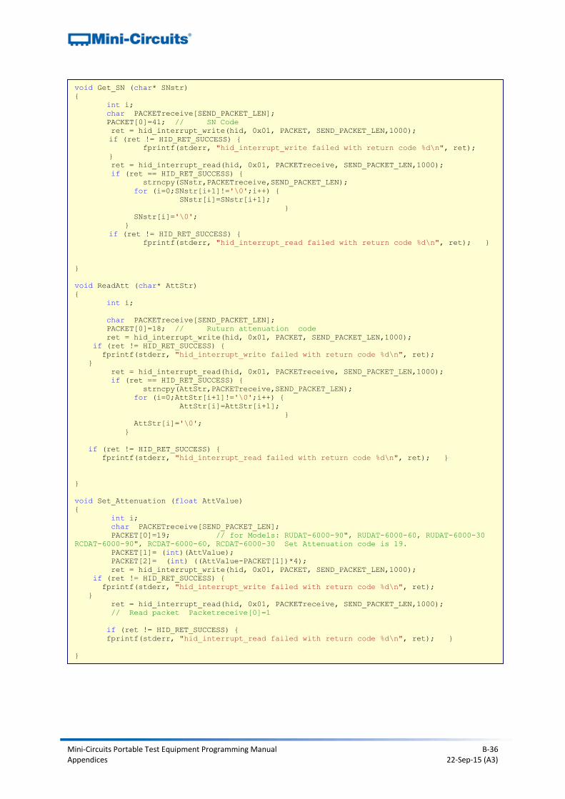
Mini-Circuits Portable Test Equipment Programming Manual B-36 Appendices 22-Sep-15 (A3)
void Get_SN (char* SNstr)
{
int i;
char PACKETreceive[SEND_PACKET_LEN];
PACKET[0]=41; // SN Code
ret = hid_interrupt_write(hid, 0x01, PACKET, SEND_PACKET_LEN,1000);
if (ret != HID_RET_SUCCESS) {
fprintf(stderr, "hid_interrupt_write failed with return code %d\n", ret);
}
ret = hid_interrupt_read(hid, 0x01, PACKETreceive, SEND_PACKET_LEN,1000);
if (ret == HID_RET_SUCCESS) {
strncpy(SNstr,PACKETreceive,SEND_PACKET_LEN);
for (i=0;SNstr[i+1]!='\0';i++) {
SNstr[i]=SNstr[i+1];
}
SNstr[i]='\0';
}
if (ret != HID_RET_SUCCESS) {
fprintf(stderr, "hid_interrupt_read failed with return code %d\n", ret); }
}
void ReadAtt (char* AttStr)
{
int i;
char PACKETreceive[SEND_PACKET_LEN];
PACKET[0]=18; // Ruturn attenuation code
ret = hid_interrupt_write(hid, 0x01, PACKET, SEND_PACKET_LEN,1000);
if (ret != HID_RET_SUCCESS) {
fprintf(stderr, "hid_interrupt_write failed with return code %d\n", ret);
}
ret = hid_interrupt_read(hid, 0x01, PACKETreceive, SEND_PACKET_LEN,1000);
if (ret == HID_RET_SUCCESS) {
strncpy(AttStr,PACKETreceive,SEND_PACKET_LEN);
for (i=0;AttStr[i+1]!='\0';i++) {
AttStr[i]=AttStr[i+1];
}
AttStr[i]='\0';
}
if (ret != HID_RET_SUCCESS) {
fprintf(stderr, "hid_interrupt_read failed with return code %d\n", ret); }
}
void Set_Attenuation (float AttValue)
{
int i;
char PACKETreceive[SEND_PACKET_LEN];
PACKET[0]=19; // for Models: RUDAT-6000-90", RUDAT-6000-60, RUDAT-6000-30
RCDAT-6000-90", RCDAT-6000-60, RCDAT-6000-30 Set Attenuation code is 19.
PACKET[1]= (int)(AttValue);
PACKET[2]= (int) ((AttValue-PACKET[1])*4);
ret = hid_interrupt_write(hid, 0x01, PACKET, SEND_PACKET_LEN,1000);
if (ret != HID_RET_SUCCESS) {
fprintf(stderr, "hid_interrupt_write failed with return code %d\n", ret);
}
ret = hid_interrupt_read(hid, 0x01, PACKETreceive, SEND_PACKET_LEN,1000);
// Read packet Packetreceive[0]=1
if (ret != HID_RET_SUCCESS) {
fprintf(stderr, "hid_interrupt_read failed with return code %d\n", ret); }
}
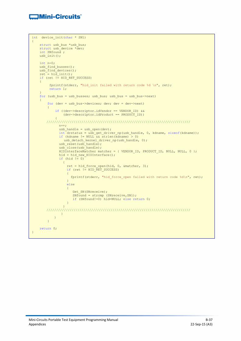
Mini-Circuits Portable Test Equipment Programming Manual B-37 Appendices 22-Sep-15 (A3)
int device_init(char * SN1)
{
struct usb_bus *usb_bus;
struct usb_device *dev;
int SNfound ;
usb_init();
int n=0;
usb_find_busses();
usb_find_devices();
ret = hid_init();
if (ret != HID_RET_SUCCESS)
{
fprintf(stderr, "hid_init failed with return code %d \n", ret);
return 1;
}
for (usb_bus = usb_busses; usb_bus; usb_bus = usb_bus->next)
{
for (dev = usb_bus->devices; dev; dev = dev->next)
{
if ((dev->descriptor.idVendor == VENDOR_ID) &&
(dev->descriptor.idProduct == PRODUCT_ID))
{
//////////////////////////////////////////////////////////////////////////
n++;
usb_handle = usb_open(dev);
int drstatus = usb_get_driver_np(usb_handle, 0, kdname, sizeof(kdname));
if (kdname != NULL && strlen(kdname) > 0)
usb_detach_kernel_driver_np(usb_handle, 0);
usb_reset(usb_handle);
usb_close(usb_handle);
HIDInterfaceMatcher matcher = { VENDOR_ID, PRODUCT_ID, NULL, NULL, 0 };
hid = hid_new_HIDInterface();
if (hid != 0)
{
ret = hid_force_open(hid, 0, &matcher, 3);
if (ret != HID_RET_SUCCESS)
{
fprintf(stderr, "hid_force_open failed with return code %d\n", ret);
}
else
{
Get_SN(SNreceive);
SNfound = strcmp (SNreceive,SN1);
if (SNfound!=0) hid=NULL; else return 0;
}
}
//////////////////////////////////////////////////////////////////////////
}
}
}
return 0;
}
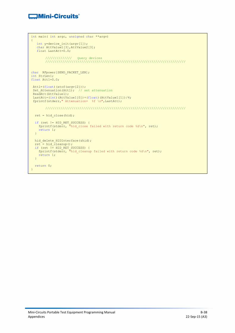
Mini-Circuits Portable Test Equipment Programming Manual B-38 Appendices 22-Sep-15 (A3)
int main( int argc, unsigned char **argv)
{
int y=device_init(argv[1]);
char AttValue1[3],AttValue2[3];
float LastAtt=0.0;
////////////// Query devices
//////////////////////////////////////////////////////////////////////////
char RFpower[SEND_PACKET_LEN];
int StrLen1;
float Att1=0.0;
Att1=(float)(atof(argv[2]));
Set_Attenuation(Att1); // set attenuation
ReadAtt(AttValue1);
LastAtt=(int)(AttValue1[0])+(float)(AttValue1[1])/4;
fprintf(stderr," Attenuation= %f \n",LastAtt);
//////////////////////////////////////////////////////////////////////////
ret = hid_close(hid);
if (ret != HID_RET_SUCCESS) {
fprintf(stderr, "hid_close failed with return code %d\n", ret);
return 1;
}
hid_delete_HIDInterface(&hid);
ret = hid_cleanup();
if (ret != HID_RET_SUCCESS) {
fprintf(stderr, "hid_cleanup failed with return code %d\n", ret);
return 1;
}
return 0;
}
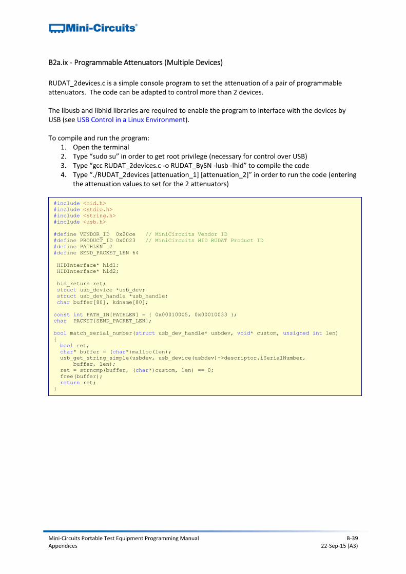
Mini-Circuits Portable Test Equipment Programming Manual B-39 Appendices 22-Sep-15 (A3)
B2a.ix - Programmable Attenuators (Multiple Devices)
RUDAT_2devices.c is a simple console program to set the attenuation of a pair of programmable attenuators. The code can be adapted to control more than 2 devices. The libusb and libhid libraries are required to enable the program to interface with the devices by USB (see USB Control in a Linux Environment). To compile and run the program:
1. Open the terminal 2. Type “sudo su” in order to get root privilege (necessary for control over USB) 3. Type “gcc RUDAT_2devices.c -o RUDAT_BySN -lusb -lhid” to compile the code 4. Type “./RUDAT_2devices [attenuation_1] [attenuation_2]” in order to run the code (entering
the attenuation values to set for the 2 attenuators)
#include <hid.h>
#include <stdio.h>
#include <string.h>
#include <usb.h>
#define VENDOR_ID 0x20ce // MiniCircuits Vendor ID
#define PRODUCT_ID 0x0023 // MiniCircuits HID RUDAT Product ID
#define PATHLEN 2
#define SEND_PACKET_LEN 64
HIDInterface* hid1;
HIDInterface* hid2;
hid_return ret;
struct usb_device *usb_dev;
struct usb_dev_handle *usb_handle;
char buffer[80], kdname[80];
const int PATH_IN[PATHLEN] = { 0x00010005, 0x00010033 };
char PACKET[SEND_PACKET_LEN];
bool match_serial_number(struct usb_dev_handle* usbdev, void* custom, unsigned int len)
{
bool ret;
char* buffer = (char*)malloc(len);
usb_get_string_simple(usbdev, usb_device(usbdev)->descriptor.iSerialNumber,
buffer, len);
ret = strncmp(buffer, (char*)custom, len) == 0;
free(buffer);
return ret;
}
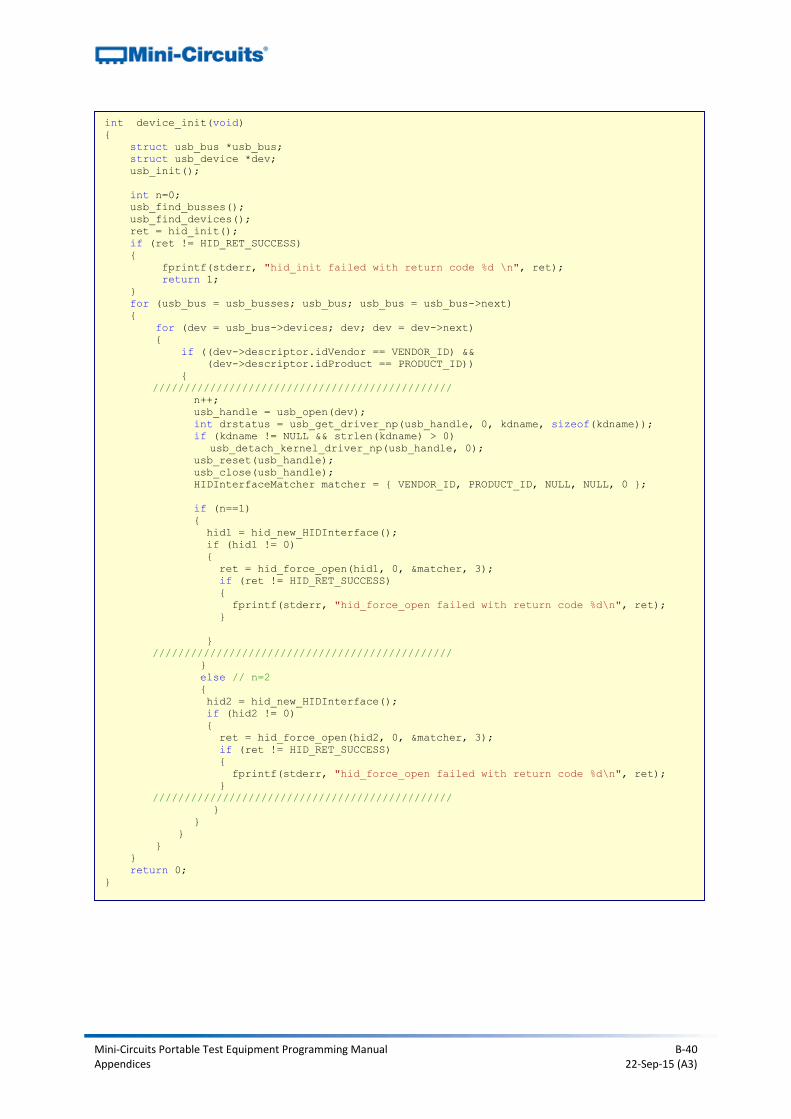
Mini-Circuits Portable Test Equipment Programming Manual B-40 Appendices 22-Sep-15 (A3)
int device_init(void)
{
struct usb_bus *usb_bus;
struct usb_device *dev;
usb_init();
int n=0;
usb_find_busses();
usb_find_devices();
ret = hid_init();
if (ret != HID_RET_SUCCESS)
{
fprintf(stderr, "hid_init failed with return code %d \n", ret);
return 1;
}
for (usb_bus = usb_busses; usb_bus; usb_bus = usb_bus->next)
{
for (dev = usb_bus->devices; dev; dev = dev->next)
{
if ((dev->descriptor.idVendor == VENDOR_ID) &&
(dev->descriptor.idProduct == PRODUCT_ID))
{
///////////////////////////////////////////////
n++;
usb_handle = usb_open(dev);
int drstatus = usb_get_driver_np(usb_handle, 0, kdname, sizeof(kdname));
if (kdname != NULL && strlen(kdname) > 0)
usb_detach_kernel_driver_np(usb_handle, 0);
usb_reset(usb_handle);
usb_close(usb_handle);
HIDInterfaceMatcher matcher = { VENDOR_ID, PRODUCT_ID, NULL, NULL, 0 };
if (n==1)
{
hid1 = hid_new_HIDInterface();
if (hid1 != 0)
{
ret = hid_force_open(hid1, 0, &matcher, 3);
if (ret != HID_RET_SUCCESS)
{
fprintf(stderr, "hid_force_open failed with return code %d\n", ret);
}
}
///////////////////////////////////////////////
}
else // n=2
{
hid2 = hid_new_HIDInterface();
if (hid2 != 0)
{
ret = hid_force_open(hid2, 0, &matcher, 3);
if (ret != HID_RET_SUCCESS)
{
fprintf(stderr, "hid_force_open failed with return code %d\n", ret);
}
///////////////////////////////////////////////
}
}
}
}
}
return 0;
}
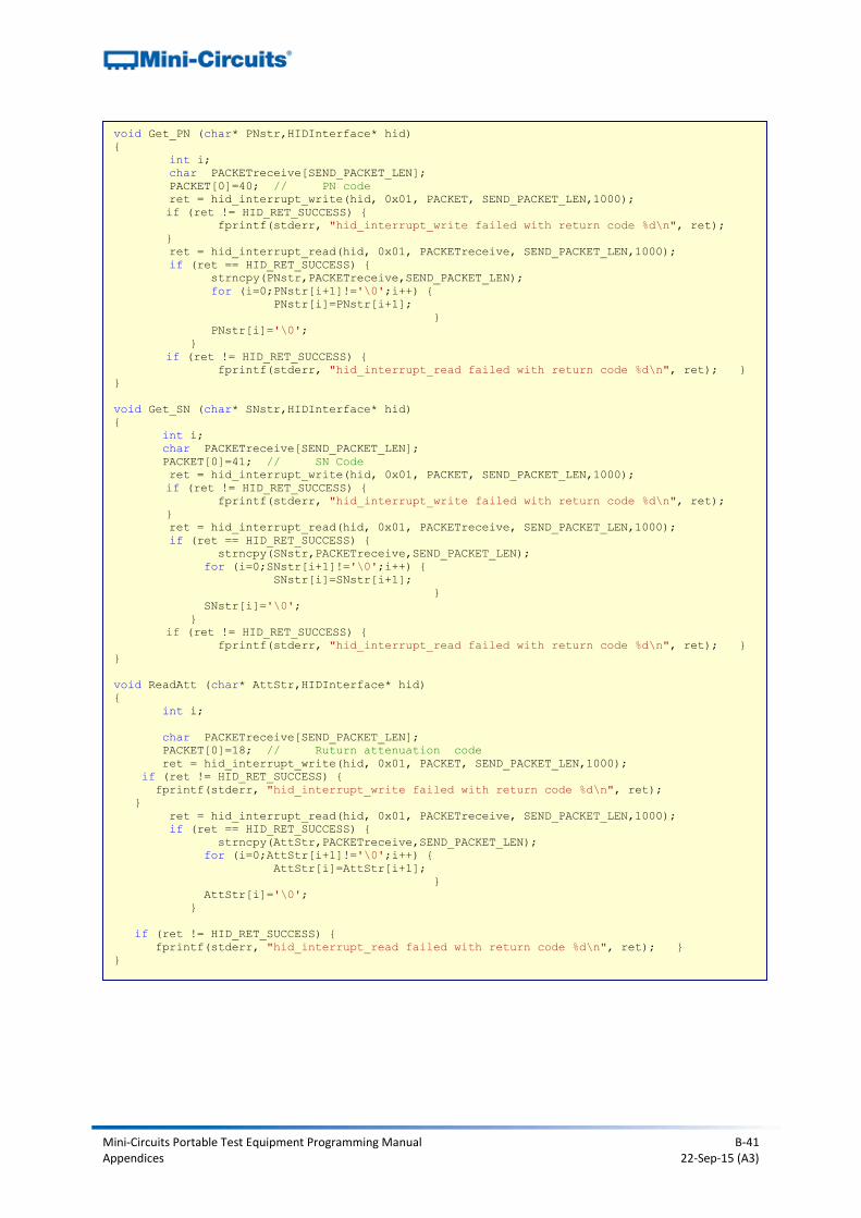
Mini-Circuits Portable Test Equipment Programming Manual B-41 Appendices 22-Sep-15 (A3)
void Get_PN (char* PNstr,HIDInterface* hid)
{
int i;
char PACKETreceive[SEND_PACKET_LEN];
PACKET[0]=40; // PN code
ret = hid_interrupt_write(hid, 0x01, PACKET, SEND_PACKET_LEN,1000);
if (ret != HID_RET_SUCCESS) {
fprintf(stderr, "hid_interrupt_write failed with return code %d\n", ret);
}
ret = hid_interrupt_read(hid, 0x01, PACKETreceive, SEND_PACKET_LEN,1000);
if (ret == HID_RET_SUCCESS) {
strncpy(PNstr,PACKETreceive,SEND_PACKET_LEN);
for (i=0;PNstr[i+1]!='\0';i++) {
PNstr[i]=PNstr[i+1];
}
PNstr[i]='\0';
}
if (ret != HID_RET_SUCCESS) {
fprintf(stderr, "hid_interrupt_read failed with return code %d\n", ret); }
}
void Get_SN (char* SNstr,HIDInterface* hid)
{
int i;
char PACKETreceive[SEND_PACKET_LEN];
PACKET[0]=41; // SN Code
ret = hid_interrupt_write(hid, 0x01, PACKET, SEND_PACKET_LEN,1000);
if (ret != HID_RET_SUCCESS) {
fprintf(stderr, "hid_interrupt_write failed with return code %d\n", ret);
}
ret = hid_interrupt_read(hid, 0x01, PACKETreceive, SEND_PACKET_LEN,1000);
if (ret == HID_RET_SUCCESS) {
strncpy(SNstr,PACKETreceive,SEND_PACKET_LEN);
for (i=0;SNstr[i+1]!='\0';i++) {
SNstr[i]=SNstr[i+1];
}
SNstr[i]='\0';
}
if (ret != HID_RET_SUCCESS) {
fprintf(stderr, "hid_interrupt_read failed with return code %d\n", ret); }
}
void ReadAtt (char* AttStr,HIDInterface* hid)
{
int i;
char PACKETreceive[SEND_PACKET_LEN];
PACKET[0]=18; // Ruturn attenuation code
ret = hid_interrupt_write(hid, 0x01, PACKET, SEND_PACKET_LEN,1000);
if (ret != HID_RET_SUCCESS) {
fprintf(stderr, "hid_interrupt_write failed with return code %d\n", ret);
}
ret = hid_interrupt_read(hid, 0x01, PACKETreceive, SEND_PACKET_LEN,1000);
if (ret == HID_RET_SUCCESS) {
strncpy(AttStr,PACKETreceive,SEND_PACKET_LEN);
for (i=0;AttStr[i+1]!='\0';i++) {
AttStr[i]=AttStr[i+1];
}
AttStr[i]='\0';
}
if (ret != HID_RET_SUCCESS) {
fprintf(stderr, "hid_interrupt_read failed with return code %d\n", ret); }
}
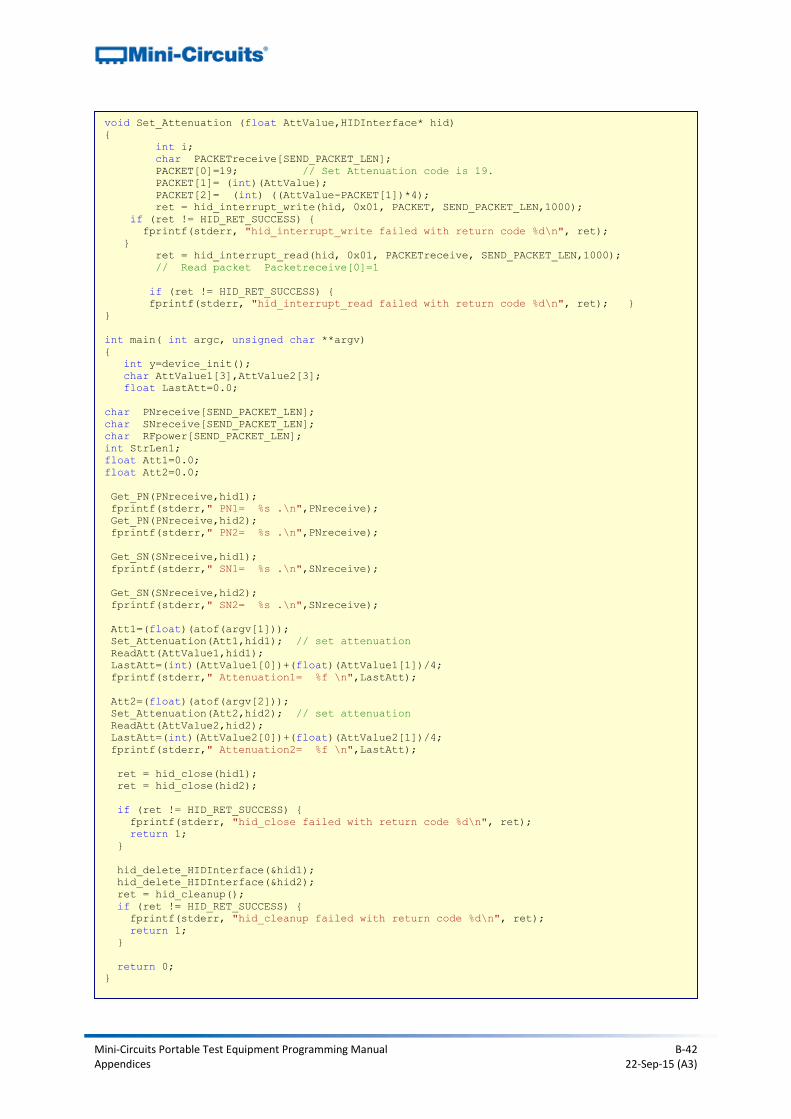
Mini-Circuits Portable Test Equipment Programming Manual B-42 Appendices 22-Sep-15 (A3)
void Set_Attenuation (float AttValue,HIDInterface* hid)
{
int i;
char PACKETreceive[SEND_PACKET_LEN];
PACKET[0]=19; // Set Attenuation code is 19.
PACKET[1]= (int)(AttValue);
PACKET[2]= (int) ((AttValue-PACKET[1])*4);
ret = hid_interrupt_write(hid, 0x01, PACKET, SEND_PACKET_LEN,1000);
if (ret != HID_RET_SUCCESS) {
fprintf(stderr, "hid_interrupt_write failed with return code %d\n", ret);
}
ret = hid_interrupt_read(hid, 0x01, PACKETreceive, SEND_PACKET_LEN,1000);
// Read packet Packetreceive[0]=1
if (ret != HID_RET_SUCCESS) {
fprintf(stderr, "hid_interrupt_read failed with return code %d\n", ret); }
}
int main( int argc, unsigned char **argv)
{
int y=device_init();
char AttValue1[3],AttValue2[3];
float LastAtt=0.0;
char PNreceive[SEND_PACKET_LEN];
char SNreceive[SEND_PACKET_LEN];
char RFpower[SEND_PACKET_LEN];
int StrLen1;
float Att1=0.0;
float Att2=0.0;
Get_PN(PNreceive,hid1);
fprintf(stderr," PN1= %s .\n",PNreceive);
Get_PN(PNreceive,hid2);
fprintf(stderr," PN2= %s .\n",PNreceive);
Get_SN(SNreceive,hid1);
fprintf(stderr," SN1= %s .\n",SNreceive);
Get_SN(SNreceive,hid2);
fprintf(stderr," SN2= %s .\n",SNreceive);
Att1=(float)(atof(argv[1]));
Set_Attenuation(Att1,hid1); // set attenuation
ReadAtt(AttValue1,hid1);
LastAtt=(int)(AttValue1[0])+(float)(AttValue1[1])/4;
fprintf(stderr," Attenuation1= %f \n",LastAtt);
Att2=(float)(atof(argv[2]));
Set_Attenuation(Att2,hid2); // set attenuation
ReadAtt(AttValue2,hid2);
LastAtt=(int)(AttValue2[0])+(float)(AttValue2[1])/4;
fprintf(stderr," Attenuation2= %f \n",LastAtt);
ret = hid_close(hid1);
ret = hid_close(hid2);
if (ret != HID_RET_SUCCESS) {
fprintf(stderr, "hid_close failed with return code %d\n", ret);
return 1;
}
hid_delete_HIDInterface(&hid1);
hid_delete_HIDInterface(&hid2);
ret = hid_cleanup();
if (ret != HID_RET_SUCCESS) {
fprintf(stderr, "hid_cleanup failed with return code %d\n", ret);
return 1;
}
return 0;
}
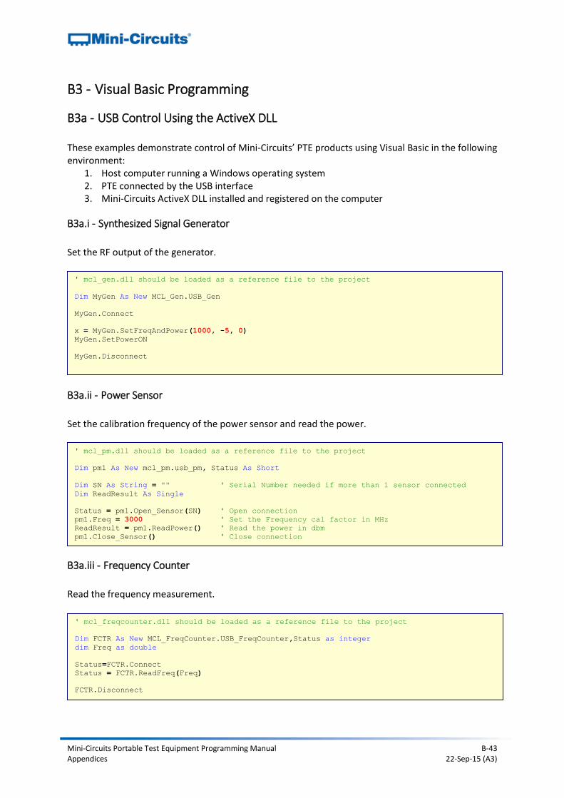
Mini-Circuits Portable Test Equipment Programming Manual B-43 Appendices 22-Sep-15 (A3)
B3 - Visual Basic Programming
B3a - USB Control Using the ActiveX DLL These examples demonstrate control of Mini-Circuits’ PTE products using Visual Basic in the following environment:
1. Host computer running a Windows operating system 2. PTE connected by the USB interface 3. Mini-Circuits ActiveX DLL installed and registered on the computer
B3a.i - Synthesized Signal Generator
Set the RF output of the generator.
B3a.ii - Power Sensor
Set the calibration frequency of the power sensor and read the power.
B3a.iii - Frequency Counter
Read the frequency measurement.
' mcl_gen.dll should be loaded as a reference file to the project
Dim MyGen As New MCL_Gen.USB_Gen
MyGen.Connect
x = MyGen.SetFreqAndPower(1000, -5, 0)
MyGen.SetPowerON
MyGen.Disconnect
' mcl_pm.dll should be loaded as a reference file to the project
Dim pm1 As New mcl_pm.usb_pm, Status As Short
Dim SN As String = "" ' Serial Number needed if more than 1 sensor connected
Dim ReadResult As Single
Status = pm1.Open_Sensor(SN) ' Open connection
pm1.Freq = 3000 ' Set the Frequency cal factor in MHz
ReadResult = pm1.ReadPower() ' Read the power in dbm
pm1.Close_Sensor() ' Close connection
' mcl_freqcounter.dll should be loaded as a reference file to the project
Dim FCTR As New MCL_FreqCounter.USB_FreqCounter,Status as integer
dim Freq as double
Status=FCTR.Connect
Status = FCTR.ReadFreq(Freq)
FCTR.Disconnect

Mini-Circuits Portable Test Equipment Programming Manual B-44 Appendices 22-Sep-15 (A3)
B3a.iv - Input/Output (IO) Control Boxes
Set the I/O Control Box relay output.
B3a.v - USB & RS232 to SPI Converters
Send SPI data from the USB port.
B3a.vi - Programmable Attenuators
Set and read the attenuation level.
' mcl_usb_to_io.dll should be loaded as a reference file to the project
Dim IO1 As New mcl_USB_To_IO.USB_IO,Status as integer
Status=IO1.Connect
Status = IO1.Set_Relay(5,1) ' Set Relay5 ON
IO1.Disconnect
' mcl_usb_rs232_to_spi.dll should be loaded as a reference file to the project
Dim SPI1 As New MCL_RS232_USB_To_SPI.USB_To_SPI
Dim ReceivedData as double, DataToSend as double
Dim x as integer
x = SPI1.Connect ' Open the connection
' Send the value 56 in 8 bits and read 8 bits from SPI
DataToSend = 56
ReceivedData = SPI1.Send_Receive_SPI(8, DataToSend, 1, 0)
SPI1.Disconnect ' Close the connection
' mcl_rudat.dll should be loaded as a reference file to the project
Dim att1 As New mcl_RUDAT.USB_DAT, Status As Short
Dim SN As String = "" ' Serial Number needed for multiple attenuators
Dim Attenuation As Single = 0
Status = att1.Connect(SN) ' Open connection
att1.SetAttenuation(37) ' Set attenuation
att1.Read_Att(Attenuation) ' Read attenuation
att1.Disconnect() ' Close connection
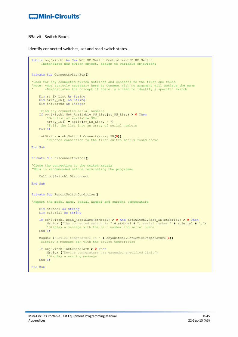
Mini-Circuits Portable Test Equipment Programming Manual B-45 Appendices 22-Sep-15 (A3)
B3a.vii - Switch Boxes
Identify connected switches, set and read switch states.
Public objSwitch1 As New MCL_RF_Switch_Controller.USB_RF_Switch
'Instantiate new switch object, assign to variable objSwitch1
Private Sub ConnectSwitchBox()
'Look for any connected switch matrices and connects to the first one found
'Note: -Not strictly necessary here as Connect with no argument will achieve the same
' -Demonstrates the concept if there is a need to identify a specific switch
Dim st_SN_List As String
Dim array_SN() As String
Dim intStatus As Integer
'Find any connected serial numbers
If objSwitch1.Get_Available_SN_List(st_SN_List) > 0 Then
'Get list of available SNs
array_SN() = Split(st_SN_List, " ")
'Split the list into an array of serial numbers
End If
intStatus = objSwitch1.Connect(array_SN(0))
'Creates connection to the first switch matrix found above
End Sub
Private Sub DisconnectSwitch()
'Close the connection to the switch matrix
'This is recommended before terminating the programme
Call objSwitch1.Disconnect
End Sub
Private Sub ReportSwitchCondition()
'Report the model name, serial number and current temperature
Dim stModel As String
Dim stSerial As String
If objSwitch1.Read_ModelName(stModel) > 0 And objSwitch1.Read_SN(stSerial) > 0 Then
MsgBox ("The connected switch is " & stModel & ", serial number " & stSerial & ".")
'Display a message with the part number and serial number
End If
MsgBox ("Device temperature is " & objSwitch1.GetDeviceTemperature(1))
'Display a message box with the device temperature
If objSwitch1.GetHeatAlarm > 0 Then
MsgBox ("Device temperature has exceeded specified limit")
'Display a warning message
End If
End Sub
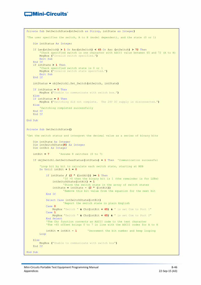
Mini-Circuits Portable Test Equipment Programming Manual B-46 Appendices 22-Sep-15 (A3)
Private Sub SetSwitchState(stSwitch as String, intState as Integer)
'The user specifies the switch, A to H (model dependent), and the state (0 or 1)
Dim intStatus As Integer
If Len(stSwitch) > 1 Or Asc(stSwitch) < 65 Or Asc (stSwitch) > 72 Then
'Check specified switch is one character with ASCII value between 65 and 72 (A to H)
MsgBox ("Invalid switch specified.")
Exit Sub
End If
If intState > 1 Then
'Check specified switch state is 0 or 1
MsgBox ("Invalid switch state specified.")
Exit Sub
End If
intStatus = objSwitch1.Set_Switch(stSwitch, intState)
If intStatus = 0 Then
MsgBox ("Unable to communicate with switch box.")
Else
If intStatus = 2 Then
MsgBox ("Switching did not complete. The 24V DC supply is disconnected.")
Else
'Switching completed successfully
End If
End If
End Sub
Private Sub GetSwitchState()
'Get the switch status and interpret the decimal value as a series of binary bits
Dim intState As Integer
Dim intSwitchState(8) As Integer
Dim intBit As Integer
intBit = 7 'Assume 8 switches (0 to 7)
If objSwitch1.GetSwitchesStatus(intState) = 1 Then 'Communication successful
'Loop bit by bit to calculate each switch state, starting at MSB
Do Until intBit + 1 = 0
If intState / (2 ^ (intBit)) >= 1 Then
'If >0 then the binary bit is 1 (the remainder is for LSBs)
intSwitchState(intBit) = 1
'Store the switch state in the array of switch states
intState = intState - (2 ^ (intBit))
'Remove this bit value from the equation for the next bit
End If
Select Case intSwitchState(intBit)
'Report the switch state in plain English
Case 0
MsgBox "Switch " & Chr(intBit + 65) & " is set Com to Port 1"
Case 1
MsgBox "Switch " & Chr(intBit + 65) & " is set Com to Port 2"
End Select
'The Chr function converts an ASCII code to the text character
'The +65 offset brings 0 to 7 in line with the ASCII codes for A to H
intBit = intBit - 1 'Decrement the bit number and keep looping
Loop
Else
MsgBox ("Unable to communicate with switch box")
End If
End Sub
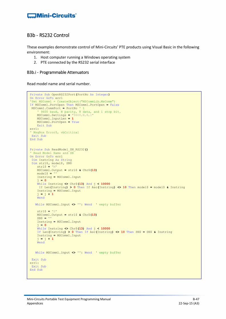
Mini-Circuits Portable Test Equipment Programming Manual B-47 Appendices 22-Sep-15 (A3)
B3b - RS232 Control These examples demonstrate control of Mini-Circuits’ PTE products using Visual Basic in the following environment:
1. Host computer running a Windows operating system 2. PTE connected by the RS232 serial interface
B3b.i - Programmable Attenuators
Read model name and serial number.
Private Sub OpenRS232Port(PortNo As Integer)
On Error GoTo err1
'Set MSComm1 = CreateObject("MSCommLib.MsComm")
If MSComm1.PortOpen Then MSComm1.PortOpen = False
MSComm1.CommPort = PortNo ' 1
' 9600 baud, N parity, 8 data, and 1 stop bit.
MSComm1.Settings = "9600,N,8,1"
MSComm1.InputLen = 1
MSComm1.PortOpen = True
Exit Sub
err1:
' MsgBox Error$, vbCritical
Exit Sub
End Sub
Private Sub ReadModel_SN_RS232()
' Read Model Name and SN
On Error GoTo err1
Dim Instring As String
Dim str1$, model$, SN$
str1$ = "M"
MSComm1.Output = str1$ & Chr$(13)
model$ = ""
Instring = MSComm1.Input
j = 0
While Instring <> Chr$(13) And j < 10000
If Len(Instring) > 0 Then If Asc(Instring) <> 10 Then model$ = model$ & Instring
Instring = MSComm1.Input
j = j + 1
Wend
While MSComm1.Input <> "": Wend ' empty buffer
str1$ = "S"
MSComm1.Output = str1$ & Chr$(13)
SN$ = ""
Instring = MSComm1.Input
j = 0
While Instring <> Chr$(13) And j < 10000
If Len(Instring) > 0 Then If Asc(Instring) <> 10 Then SN$ = SN$ & Instring
Instring = MSComm1.Input
j = j + 1
Wend
While MSComm1.Input <> "": Wend ' empty buffer
Exit Sub
err1:
Exit Sub
End Sub

Mini-Circuits Portable Test Equipment Programming Manual B-48 Appendices 22-Sep-15 (A3)
B3b.ii - RS232 to SPI Converters
Read model name/serial number and send SPI data.
Private Sub OpenRS232Port(PortNo As Integer)
On Error GoTo err1
'Set MSComm1 = CreateObject("MSCommLib.MsComm")
If MSComm1.PortOpen Then MSComm1.PortOpen = False
MSComm1.CommPort = PortNo ' 1
' 9600 baud, E parity, 8 data, and 1 stop bit.
MSComm1.Settings = "9600,E,8,1"
MSComm1.InputLen = 1
MSComm1.PortOpen = True
Exit Sub
err1:
' MsgBox Error$, vbCritical
Exit Sub
End Sub
Private Sub ReadModel_SN_RS232()
' Read Model Name and SN
On Error GoTo err1
Dim Instring As String
Dim str1$, model$, SN$
str1$ = "M"
MSComm1.Output = str1$ & Chr$(13)
model$ = ""
Instring = MSComm1.Input
j = 0
While Instring <> Chr$(13) And j < 10000
If Len(Instring) > 0 Then If Asc(Instring) <> 10 Then model$ = model$ & Instring
Instring = MSComm1.Input
j = j + 1
Wend
While MSComm1.Input <> "": Wend ' empty buffer
str1$ = "S"
MSComm1.Output = str1$ & Chr$(13)
SN$ = ""
Instring = MSComm1.Input
j = 0
While Instring <> Chr$(13) And j < 10000
If Len(Instring) > 0 Then If Asc(Instring) <> 10 Then SN$ = SN$ & Instring
Instring = MSComm1.Input
j = j + 1
Wend
While MSComm1.Input <> "": Wend ' empty buffer
Exit Sub
err1:
Exit Sub
End Sub
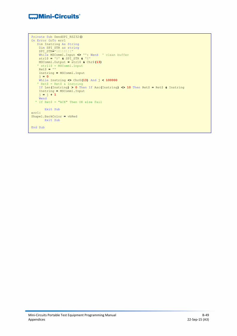
Mini-Circuits Portable Test Equipment Programming Manual B-49 Appendices 22-Sep-15 (A3)
Private Sub SendSPI_RS232()
On Error GoTo err1
Dim Instring As String
Dim SPI_STR as string
SPI_STR="10110111"
While MSComm1.Input <> "": Wend ' clean buffer
str1$ = "B" & SPI_STR & "E"
MSComm1.Output = str1$ & Chr$(13)
' str11$ = MSComm1.Input
Ret$ = ""
Instring = MSComm1.Input
j = 0
While Instring <> Chr$(13) And j < 100000
' Ret$ = Ret$ & Instring
If Len(Instring) > 0 Then If Asc(Instring) <> 10 Then Ret$ = Ret$ & Instring
Instring = MSComm1.Input
j = j + 1
Wend
' If Ret$ = "ACK" Then OK else Fail
Exit Sub
err1:
Shape1.BackColor = vbRed
Exit Sub
End Sub
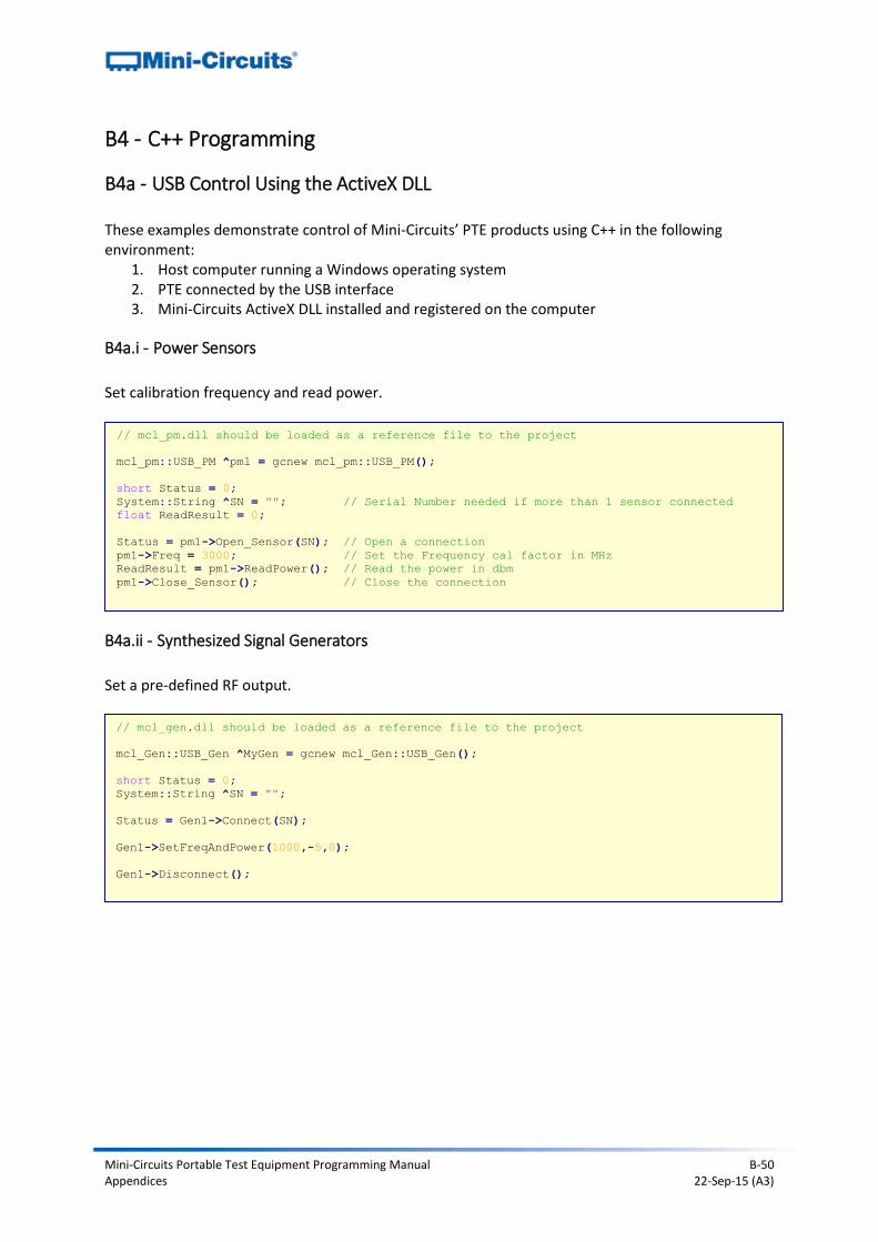
Mini-Circuits Portable Test Equipment Programming Manual B-50 Appendices 22-Sep-15 (A3)
B4 - C++ Programming
B4a - USB Control Using the ActiveX DLL These examples demonstrate control of Mini-Circuits’ PTE products using C++ in the following environment:
1. Host computer running a Windows operating system 2. PTE connected by the USB interface 3. Mini-Circuits ActiveX DLL installed and registered on the computer
B4a.i - Power Sensors
Set calibration frequency and read power.
B4a.ii - Synthesized Signal Generators
Set a pre-defined RF output.
// mcl_pm.dll should be loaded as a reference file to the project
mcl_pm::USB_PM ^pm1 = gcnew mcl_pm::USB_PM();
short Status = 0;
System::String ^SN = ""; // Serial Number needed if more than 1 sensor connected
float ReadResult = 0;
Status = pm1->Open_Sensor(SN); // Open a connection
pm1->Freq = 3000; // Set the Frequency cal factor in MHz
ReadResult = pm1->ReadPower(); // Read the power in dbm
pm1->Close_Sensor(); // Close the connection
// mcl_gen.dll should be loaded as a reference file to the project
mcl_Gen::USB_Gen ^MyGen = gcnew mcl_Gen::USB_Gen();
short Status = 0;
System::String ^SN = "";
Status = Gen1->Connect(SN);
Gen1->SetFreqAndPower(1000,-5,0);
Gen1->Disconnect();
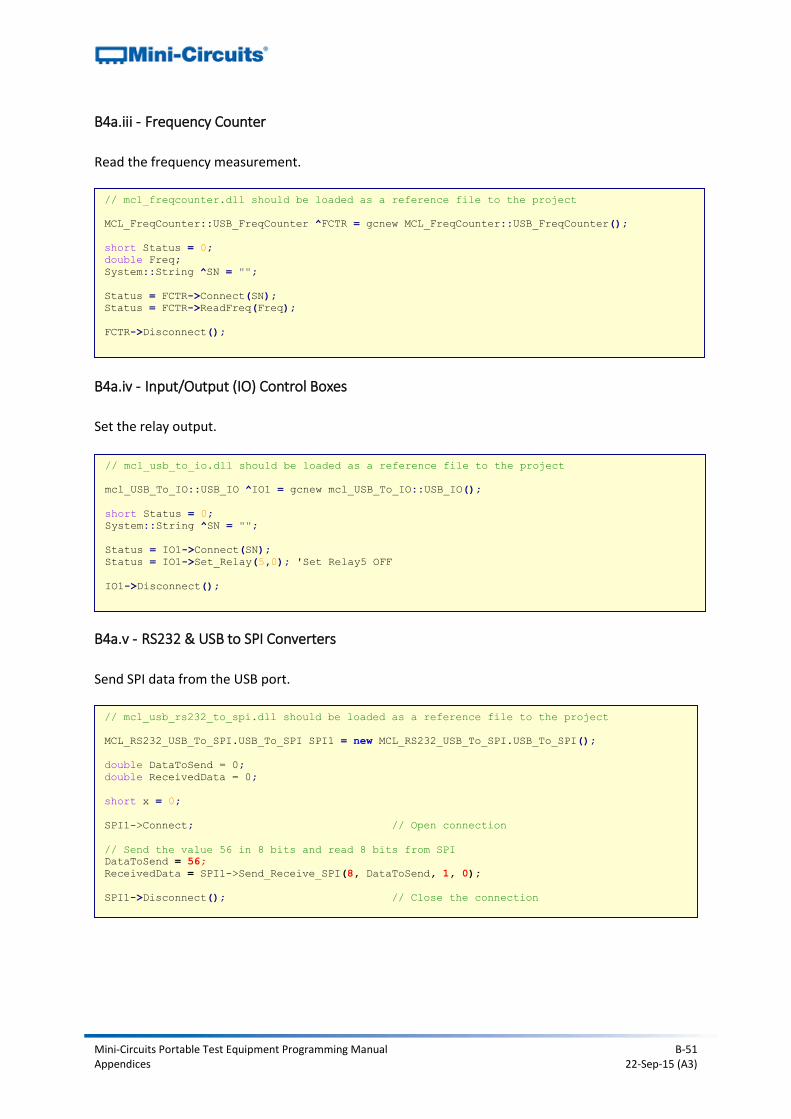
Mini-Circuits Portable Test Equipment Programming Manual B-51 Appendices 22-Sep-15 (A3)
B4a.iii - Frequency Counter
Read the frequency measurement.
B4a.iv - Input/Output (IO) Control Boxes
Set the relay output.
B4a.v - RS232 & USB to SPI Converters
Send SPI data from the USB port.
// mcl_freqcounter.dll should be loaded as a reference file to the project
MCL_FreqCounter::USB_FreqCounter ^FCTR = gcnew MCL_FreqCounter::USB_FreqCounter();
short Status = 0;
double Freq;
System::String ^SN = "";
Status = FCTR->Connect(SN);
Status = FCTR->ReadFreq(Freq);
FCTR->Disconnect();
// mcl_usb_to_io.dll should be loaded as a reference file to the project
mcl_USB_To_IO::USB_IO ^IO1 = gcnew mcl_USB_To_IO::USB_IO();
short Status = 0;
System::String ^SN = "";
Status = IO1->Connect(SN);
Status = IO1->Set_Relay(5,0); 'Set Relay5 OFF
IO1->Disconnect();
// mcl_usb_rs232_to_spi.dll should be loaded as a reference file to the project
MCL_RS232_USB_To_SPI.USB_To_SPI SPI1 = new MCL_RS232_USB_To_SPI.USB_To_SPI();
double DataToSend = 0;
double ReceivedData = 0;
short x = 0;
SPI1->Connect; // Open connection
// Send the value 56 in 8 bits and read 8 bits from SPI
DataToSend = 56;
ReceivedData = SPI1->Send_Receive_SPI(8, DataToSend, 1, 0);
SPI1->Disconnect(); // Close the connection
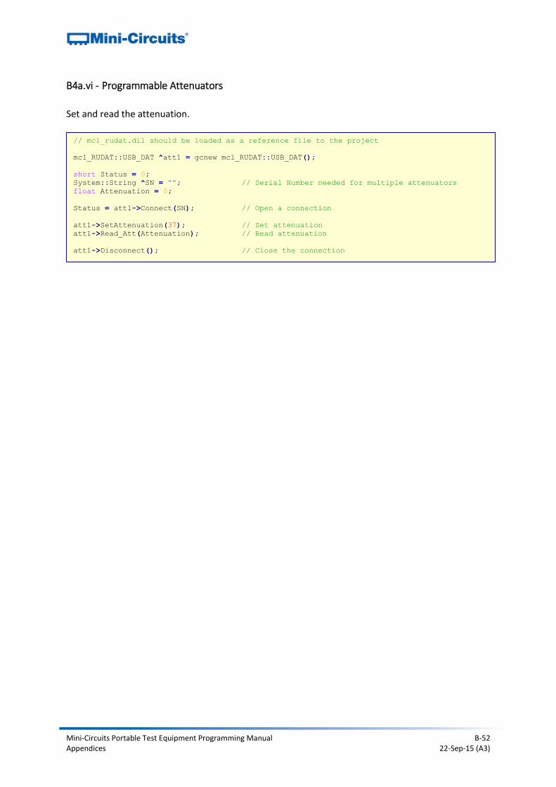
Mini-Circuits Portable Test Equipment Programming Manual B-52 Appendices 22-Sep-15 (A3)
B4a.vi - Programmable Attenuators
Set and read the attenuation.
// mcl_rudat.dll should be loaded as a reference file to the project
mcl_RUDAT::USB_DAT ^att1 = gcnew mcl_RUDAT::USB_DAT();
short Status = 0;
System::String ^SN = ""; // Serial Number needed for multiple attenuators
float Attenuation = 0;
Status = att1->Connect(SN); // Open a connection
att1->SetAttenuation(37); // Set attenuation
att1->Read_Att(Attenuation); // Read attenuation
att1->Disconnect(); // Close the connection
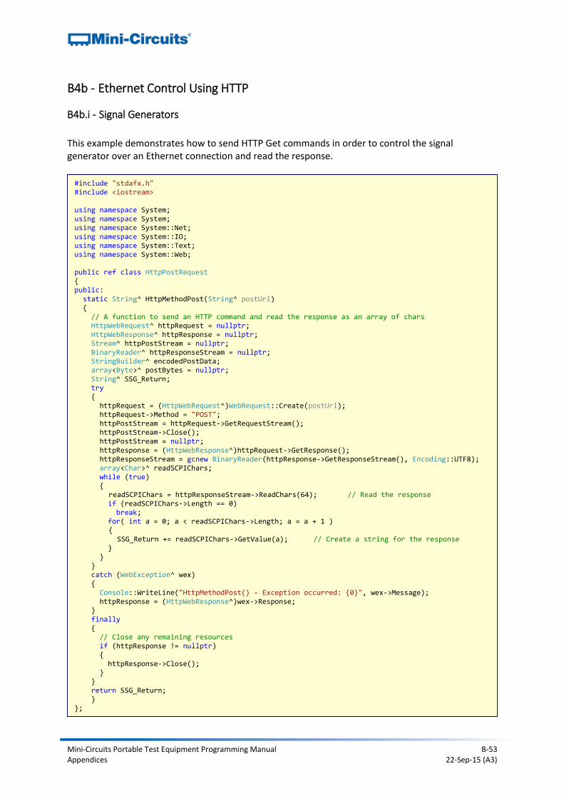
Mini-Circuits Portable Test Equipment Programming Manual B-53 Appendices 22-Sep-15 (A3)
B4b - Ethernet Control Using HTTP
B4b.i - Signal Generators
This example demonstrates how to send HTTP Get commands in order to control the signal generator over an Ethernet connection and read the response.
#include "stdafx.h" #include <iostream> using namespace System; using namespace System; using namespace System::Net; using namespace System::IO; using namespace System::Text; using namespace System::Web; public ref class HttpPostRequest { public: static String^ HttpMethodPost(String^ postUrl) { // A function to send an HTTP command and read the response as an array of chars HttpWebRequest^ httpRequest = nullptr; HttpWebResponse^ httpResponse = nullptr; Stream^ httpPostStream = nullptr; BinaryReader^ httpResponseStream = nullptr; StringBuilder^ encodedPostData; array<Byte>^ postBytes = nullptr; String^ SSG_Return; try { httpRequest = (HttpWebRequest^)WebRequest::Create(postUrl); httpRequest->Method = "POST"; httpPostStream = httpRequest->GetRequestStream(); httpPostStream->Close(); httpPostStream = nullptr; httpResponse = (HttpWebResponse^)httpRequest->GetResponse(); httpResponseStream = gcnew BinaryReader(httpResponse->GetResponseStream(), Encoding::UTF8); array<Char>^ readSCPIChars; while (true) { readSCPIChars = httpResponseStream->ReadChars(64); // Read the response if (readSCPIChars->Length == 0) break; for( int a = 0; a < readSCPIChars->Length; a = a + 1 ) { SSG_Return += readSCPIChars->GetValue(a); // Create a string for the response } } } catch (WebException^ wex) { Console::WriteLine("HttpMethodPost() - Exception occurred: {0}", wex->Message); httpResponse = (HttpWebResponse^)wex->Response; } finally { // Close any remaining resources if (httpResponse != nullptr) { httpResponse->Close(); } } return SSG_Return; } };
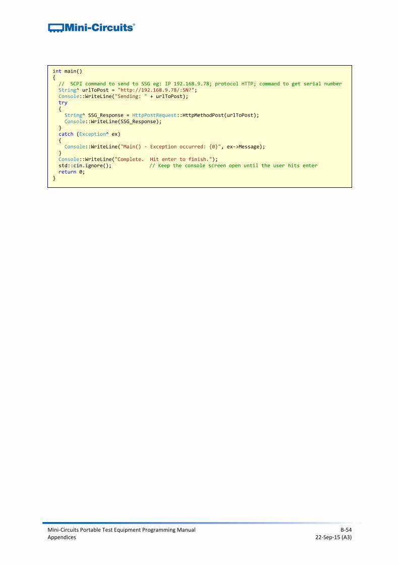
Mini-Circuits Portable Test Equipment Programming Manual B-54 Appendices 22-Sep-15 (A3)
int main() { // SCPI command to send to SSG eg: IP 192.168.9.78; protocol HTTP; command to get serial number String^ urlToPost = "http://192.168.9.78/:SN?"; Console::WriteLine("Sending: " + urlToPost); try { String^ SSG_Response = HttpPostRequest::HttpMethodPost(urlToPost); Console::WriteLine(SSG_Response); } catch (Exception^ ex) { Console::WriteLine("Main() - Exception occurred: {0}", ex->Message); } Console::WriteLine("Complete. Hit enter to finish."); std::cin.ignore(); // Keep the console screen open until the user hits enter return 0; }
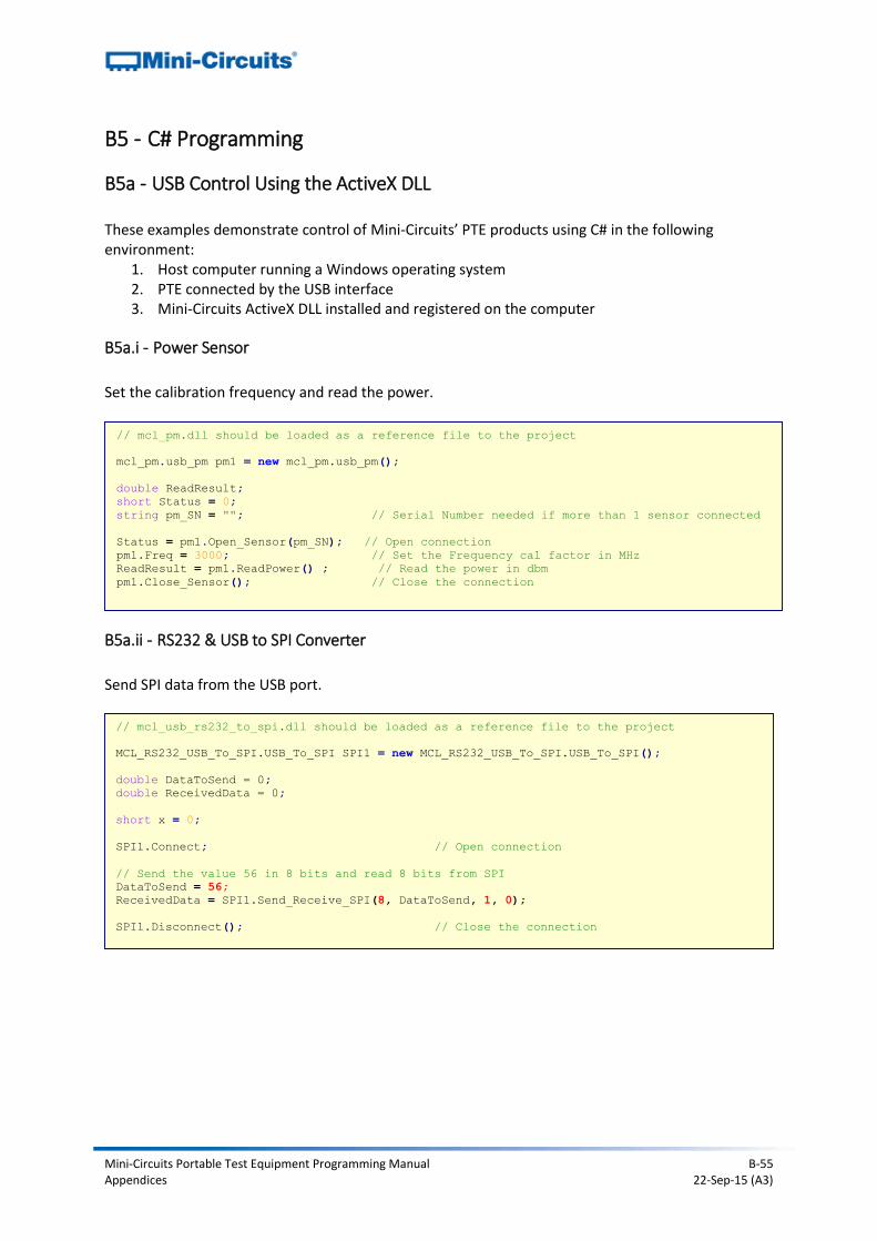
Mini-Circuits Portable Test Equipment Programming Manual B-55 Appendices 22-Sep-15 (A3)
B5 - C# Programming
B5a - USB Control Using the ActiveX DLL These examples demonstrate control of Mini-Circuits’ PTE products using C# in the following environment:
1. Host computer running a Windows operating system 2. PTE connected by the USB interface 3. Mini-Circuits ActiveX DLL installed and registered on the computer
B5a.i - Power Sensor
Set the calibration frequency and read the power.
B5a.ii - RS232 & USB to SPI Converter
Send SPI data from the USB port.
// mcl_pm.dll should be loaded as a reference file to the project
mcl_pm.usb_pm pm1 = new mcl_pm.usb_pm();
double ReadResult;
short Status = 0;
string pm_SN = ""; // Serial Number needed if more than 1 sensor connected
Status = pm1.Open_Sensor(pm_SN); // Open connection
pm1.Freq = 3000; // Set the Frequency cal factor in MHz
ReadResult = pm1.ReadPower() ; // Read the power in dbm
pm1.Close_Sensor(); // Close the connection
// mcl_usb_rs232_to_spi.dll should be loaded as a reference file to the project
MCL_RS232_USB_To_SPI.USB_To_SPI SPI1 = new MCL_RS232_USB_To_SPI.USB_To_SPI();
double DataToSend = 0;
double ReceivedData = 0;
short x = 0;
SPI1.Connect; // Open connection
// Send the value 56 in 8 bits and read 8 bits from SPI
DataToSend = 56;
ReceivedData = SPI1.Send_Receive_SPI(8, DataToSend, 1, 0);
SPI1.Disconnect(); // Close the connection
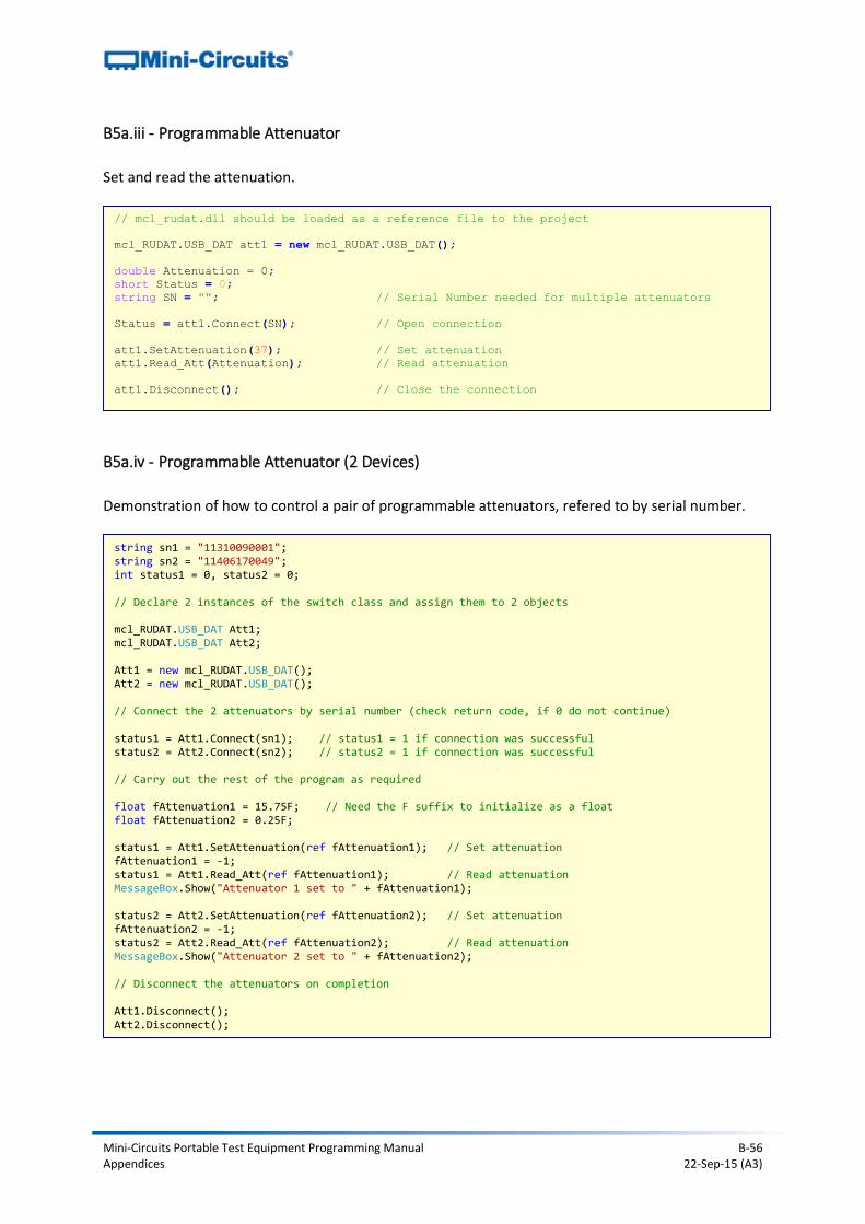
Mini-Circuits Portable Test Equipment Programming Manual B-56 Appendices 22-Sep-15 (A3)
B5a.iii - Programmable Attenuator
Set and read the attenuation.
B5a.iv - Programmable Attenuator (2 Devices)
Demonstration of how to control a pair of programmable attenuators, refered to by serial number.
// mcl_rudat.dll should be loaded as a reference file to the project
mcl_RUDAT.USB_DAT att1 = new mcl_RUDAT.USB_DAT();
double Attenuation = 0;
short Status = 0;
string SN = ""; // Serial Number needed for multiple attenuators
Status = att1.Connect(SN); // Open connection
att1.SetAttenuation(37); // Set attenuation
att1.Read_Att(Attenuation); // Read attenuation
att1.Disconnect(); // Close the connection
string sn1 = "11310090001"; string sn2 = "11406170049"; int status1 = 0, status2 = 0; // Declare 2 instances of the switch class and assign them to 2 objects mcl_RUDAT.USB_DAT Att1; mcl_RUDAT.USB_DAT Att2; Att1 = new mcl_RUDAT.USB_DAT(); Att2 = new mcl_RUDAT.USB_DAT(); // Connect the 2 attenuators by serial number (check return code, if 0 do not continue) status1 = Att1.Connect(sn1); // status1 = 1 if connection was successful status2 = Att2.Connect(sn2); // status2 = 1 if connection was successful // Carry out the rest of the program as required float fAttenuation1 = 15.75F; // Need the F suffix to initialize as a float float fAttenuation2 = 0.25F; status1 = Att1.SetAttenuation(ref fAttenuation1); // Set attenuation fAttenuation1 = -1; status1 = Att1.Read_Att(ref fAttenuation1); // Read attenuation MessageBox.Show("Attenuator 1 set to " + fAttenuation1); status2 = Att2.SetAttenuation(ref fAttenuation2); // Set attenuation fAttenuation2 = -1; status2 = Att2.Read_Att(ref fAttenuation2); // Read attenuation MessageBox.Show("Attenuator 2 set to " + fAttenuation2); // Disconnect the attenuators on completion Att1.Disconnect(); Att2.Disconnect();
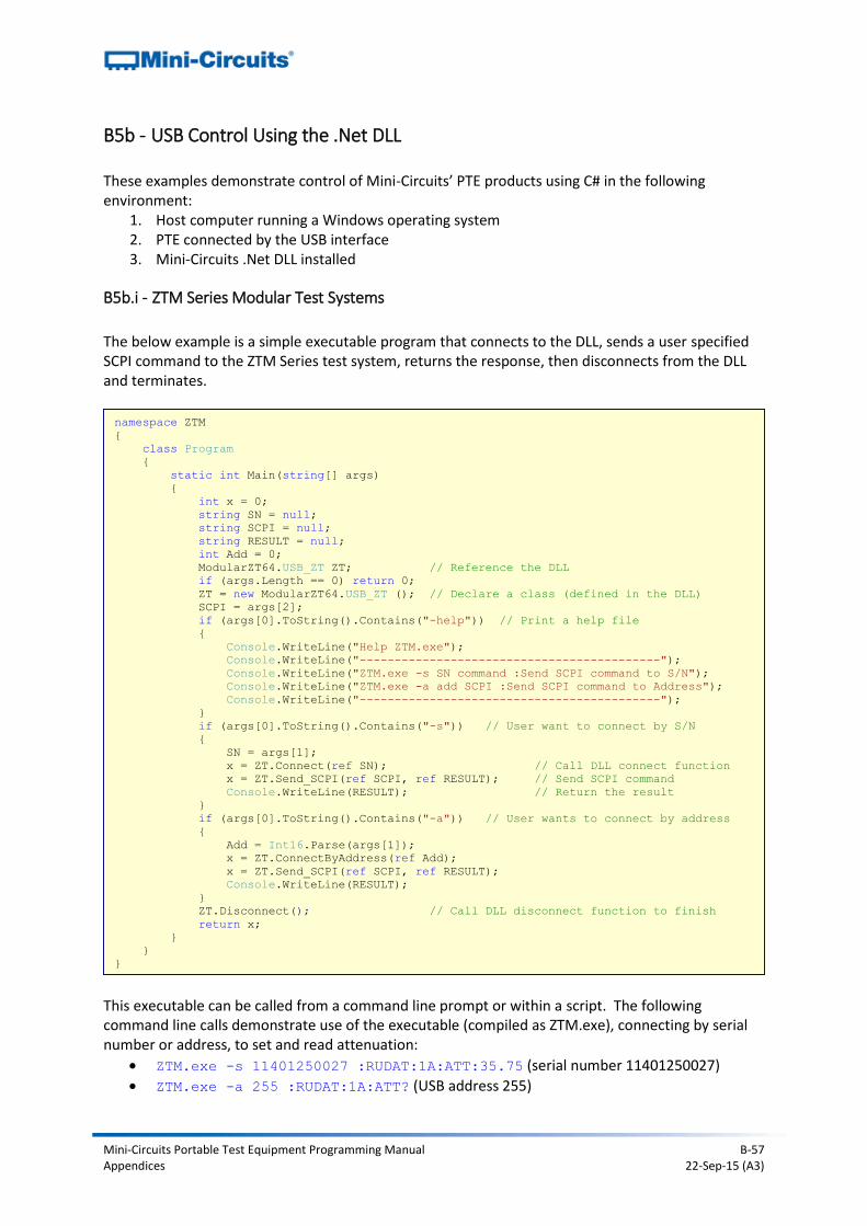
Mini-Circuits Portable Test Equipment Programming Manual B-57 Appendices 22-Sep-15 (A3)
B5b - USB Control Using the .Net DLL These examples demonstrate control of Mini-Circuits’ PTE products using C# in the following environment:
1. Host computer running a Windows operating system 2. PTE connected by the USB interface 3. Mini-Circuits .Net DLL installed
B5b.i - ZTM Series Modular Test Systems
The below example is a simple executable program that connects to the DLL, sends a user specified SCPI command to the ZTM Series test system, returns the response, then disconnects from the DLL and terminates.
This executable can be called from a command line prompt or within a script. The following command line calls demonstrate use of the executable (compiled as ZTM.exe), connecting by serial number or address, to set and read attenuation:
ZTM.exe -s 11401250027 :RUDAT:1A:ATT:35.75 (serial number 11401250027)
ZTM.exe -a 255 :RUDAT:1A:ATT? (USB address 255)
namespace ZTM
{
class Program
{
static int Main(string[] args)
{
int x = 0;
string SN = null;
string SCPI = null;
string RESULT = null;
int Add = 0;
ModularZT64.USB_ZT ZT; // Reference the DLL
if (args.Length == 0) return 0;
ZT = new ModularZT64.USB_ZT (); // Declare a class (defined in the DLL)
SCPI = args[2];
if (args[0].ToString().Contains("-help")) // Print a help file
{
Console.WriteLine("Help ZTM.exe");
Console.WriteLine("-------------------------------------------");
Console.WriteLine("ZTM.exe -s SN command :Send SCPI command to S/N");
Console.WriteLine("ZTM.exe -a add SCPI :Send SCPI command to Address");
Console.WriteLine("-------------------------------------------");
}
if (args[0].ToString().Contains("-s")) // User want to connect by S/N
{
SN = args[1];
x = ZT.Connect(ref SN); // Call DLL connect function
x = ZT.Send_SCPI(ref SCPI, ref RESULT); // Send SCPI command
Console.WriteLine(RESULT); // Return the result
}
if (args[0].ToString().Contains("-a")) // User wants to connect by address
{
Add = Int16.Parse(args[1]);
x = ZT.ConnectByAddress(ref Add);
x = ZT.Send_SCPI(ref SCPI, ref RESULT);
Console.WriteLine(RESULT);
}
ZT.Disconnect(); // Call DLL disconnect function to finish
return x;
}
}
}
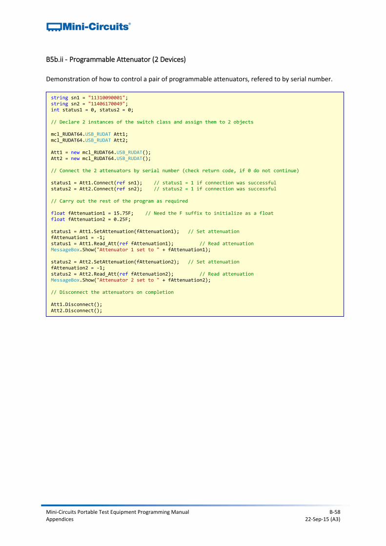
Mini-Circuits Portable Test Equipment Programming Manual B-58 Appendices 22-Sep-15 (A3)
B5b.ii - Programmable Attenuator (2 Devices)
Demonstration of how to control a pair of programmable attenuators, refered to by serial number.
string sn1 = "11310090001"; string sn2 = "11406170049"; int status1 = 0, status2 = 0; // Declare 2 instances of the switch class and assign them to 2 objects mcl_RUDAT64.USB_RUDAT Att1; mcl_RUDAT64.USB_RUDAT Att2; Att1 = new mcl_RUDAT64.USB_RUDAT(); Att2 = new mcl_RUDAT64.USB_RUDAT(); // Connect the 2 attenuators by serial number (check return code, if 0 do not continue) status1 = Att1.Connect(ref sn1); // status1 = 1 if connection was successful status2 = Att2.Connect(ref sn2); // status2 = 1 if connection was successful // Carry out the rest of the program as required float fAttenuation1 = 15.75F; // Need the F suffix to initialize as a float float fAttenuation2 = 0.25F; status1 = Att1.SetAttenuation(fAttenuation1); // Set attenuation fAttenuation1 = -1; status1 = Att1.Read_Att(ref fAttenuation1); // Read attenuation MessageBox.Show("Attenuator 1 set to " + fAttenuation1); status2 = Att2.SetAttenuation(fAttenuation2); // Set attenuation fAttenuation2 = -1; status2 = Att2.Read_Att(ref fAttenuation2); // Read attenuation MessageBox.Show("Attenuator 2 set to " + fAttenuation2); // Disconnect the attenuators on completion Att1.Disconnect(); Att2.Disconnect();
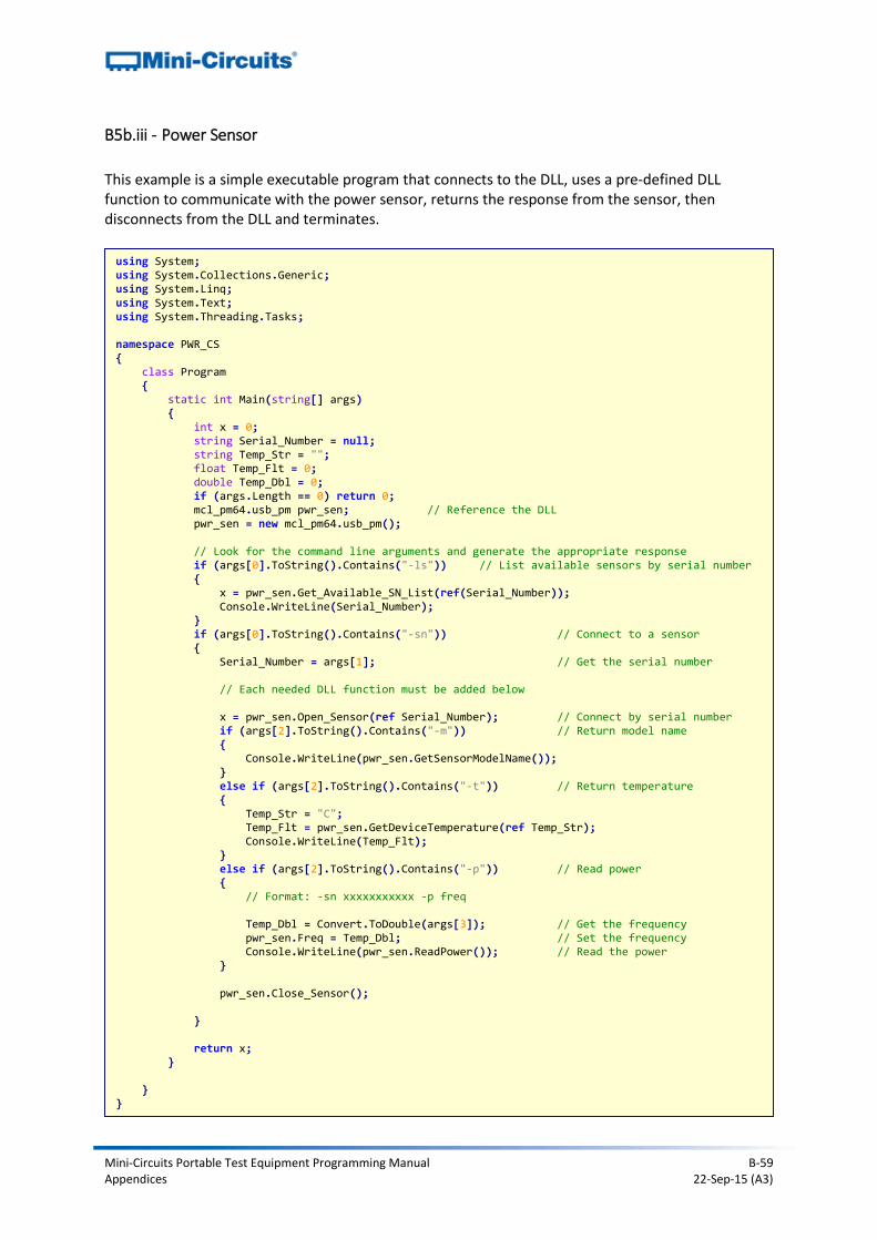
Mini-Circuits Portable Test Equipment Programming Manual B-59 Appendices 22-Sep-15 (A3)
B5b.iii - Power Sensor
This example is a simple executable program that connects to the DLL, uses a pre-defined DLL function to communicate with the power sensor, returns the response from the sensor, then disconnects from the DLL and terminates.
using System; using System.Collections.Generic; using System.Linq; using System.Text; using System.Threading.Tasks; namespace PWR_CS { class Program { static int Main(string[] args) { int x = 0; string Serial_Number = null; string Temp_Str = ""; float Temp_Flt = 0; double Temp_Dbl = 0; if (args.Length == 0) return 0; mcl_pm64.usb_pm pwr_sen; // Reference the DLL pwr_sen = new mcl_pm64.usb_pm(); // Look for the command line arguments and generate the appropriate response if (args[0].ToString().Contains("-ls")) // List available sensors by serial number { x = pwr_sen.Get_Available_SN_List(ref(Serial_Number)); Console.WriteLine(Serial_Number); } if (args[0].ToString().Contains("-sn")) // Connect to a sensor { Serial_Number = args[1]; // Get the serial number // Each needed DLL function must be added below x = pwr_sen.Open_Sensor(ref Serial_Number); // Connect by serial number if (args[2].ToString().Contains("-m")) // Return model name { Console.WriteLine(pwr_sen.GetSensorModelName()); } else if (args[2].ToString().Contains("-t")) // Return temperature { Temp_Str = "C"; Temp_Flt = pwr_sen.GetDeviceTemperature(ref Temp_Str); Console.WriteLine(Temp_Flt); } else if (args[2].ToString().Contains("-p")) // Read power { // Format: -sn xxxxxxxxxxx -p freq Temp_Dbl = Convert.ToDouble(args[3]); // Get the frequency pwr_sen.Freq = Temp_Dbl; // Set the frequency Console.WriteLine(pwr_sen.ReadPower()); // Read the power } pwr_sen.Close_Sensor(); } return x; } } }

Mini-Circuits Portable Test Equipment Programming Manual B-60 Appendices 22-Sep-15 (A3)
The purpose of the executable is to enclose the .NET DLL interaction and functionality within a simple console application that can be called from elsewhere. This allows the executable to act as a middle layer between a programming environment which does not provide .NET support (typical Python 64-bit distributions for example) and one that does (Visual C#) so that the power sensor's functionality can be used in the former without directly accessing the DLL. To run the application, the command line takes the below form (assuming the executable is compiled as pwr_cs.exe and the power sensor has serial number 1150825015):
pwr_cs.exe –ls List all serial numbers for connected sensors
pwr_cs.exe –sn 11508250015 –m Return the model name
pwr_cs.exe –sn 11508250015 –t Return the temperature
pwr_cs.exe –sn 11508250015 –p 1500 Read power at 1500 MHz
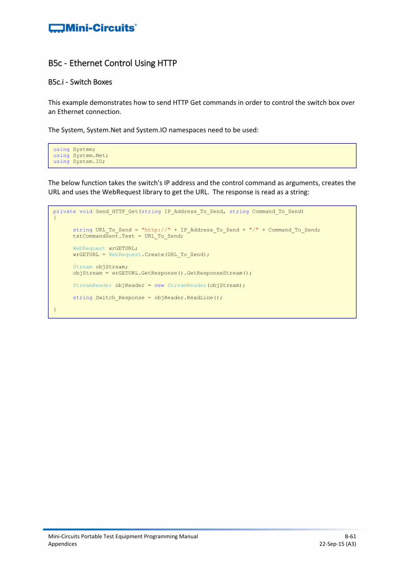
Mini-Circuits Portable Test Equipment Programming Manual B-61 Appendices 22-Sep-15 (A3)
B5c - Ethernet Control Using HTTP
B5c.i - Switch Boxes
This example demonstrates how to send HTTP Get commands in order to control the switch box over an Ethernet connection. The System, System.Net and System.IO namespaces need to be used:
The below function takes the switch's IP address and the control command as arguments, creates the URL and uses the WebRequest library to get the URL. The response is read as a string:
using System;
using System.Net;
using System.IO;
private void Send_HTTP_Get(string IP_Address_To_Send, string Command_To_Send)
{
string URL_To_Send = "http://" + IP_Address_To_Send + "/" + Command_To_Send;
txtCommandSent.Text = URL_To_Send;
WebRequest wrGETURL;
wrGETURL = WebRequest.Create(URL_To_Send);
Stream objStream;
objStream = wrGETURL.GetResponse().GetResponseStream();
StreamReader objReader = new StreamReader(objStream);
string Switch_Response = objReader.ReadLine();
}
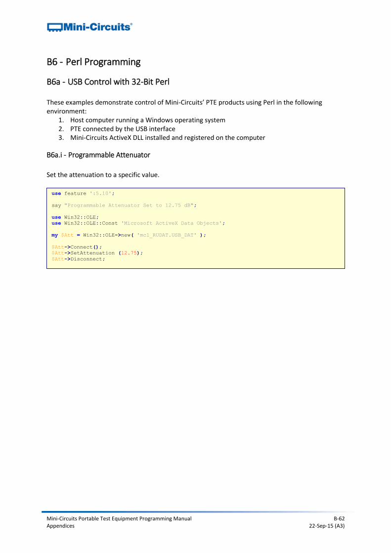
Mini-Circuits Portable Test Equipment Programming Manual B-62 Appendices 22-Sep-15 (A3)
B6 - Perl Programming
B6a - USB Control with 32-Bit Perl These examples demonstrate control of Mini-Circuits’ PTE products using Perl in the following environment:
1. Host computer running a Windows operating system 2. PTE connected by the USB interface 3. Mini-Circuits ActiveX DLL installed and registered on the computer
B6a.i - Programmable Attenuator
Set the attenuation to a specific value.
use feature ':5.10';
say "Programmable Attenuator Set to 12.75 dB";
use Win32::OLE;
use Win32::OLE::Const 'Microsoft ActiveX Data Objects';
my $Att = Win32::OLE->new( 'mcl_RUDAT.USB_DAT' );
$Att->Connect();
$Att->SetAttenuation (12.75);
$Att->Disconnect;
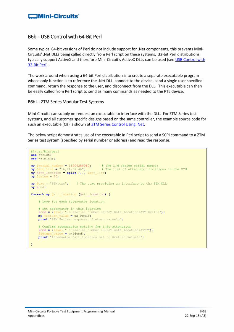
Mini-Circuits Portable Test Equipment Programming Manual B-63 Appendices 22-Sep-15 (A3)
B6b - USB Control with 64-Bit Perl Some typical 64-bit versions of Perl do not include support for .Net components, this prevents Mini-Circuits' .Net DLLs being called directly from Perl script on these systems. 32-bit Perl distributions typically support ActiveX and therefore Mini-Circuit's ActiveX DLLs can be used (see USB Control with 32-Bit Perl). The work around when using a 64-bit Perl distribution is to create a separate executable program whose only function is to reference the .Net DLL, connect to the device, send a single user specified command, return the response to the user, and disconnect from the DLL. This executable can then be easily called from Perl script to send as many commands as needed to the PTE device.
B6b.i - ZTM Series Modular Test Systems
Mini-Circuits can supply on request an executable to interface with the DLL. For ZTM Series test systems, and all customer specific designs based on the same controller, the example source code for such an executable (C#) is shown at ZTM Series Control Using .Net. The below script demonstrates use of the executable in Perl script to send a SCPI command to a ZTM Series test system (specified by serial number or address) and read the response.
#!/usr/bin/perl
use strict;
use warnings;
my $serial_number = 11404280010; # The ZTM Series serial number
my $att_list = "1A,2A,3A,4A"; # The list of attenuator locations in the ZTM
my @att_location = split /,/, $att_list;
my $value = 40;
my $exe = "ZTM.exe"; # The .exe providing an interface to the ZTM DLL
my @cmd;
foreach my $att_location (@att_location) {
# Loop for each attenuator location
# Set attenuator in this location
@cmd = ($exe, "-s $serial_number :RUDAT:$att_location:ATT:$value");
my $return_value = qx{@cmd};
print "ZTM Series response: $return_value\n";
# Confirm attenuation setting for this attenuator
@cmd = ($exe, "-s $serial_number :RUDAT:$att_location:ATT?");
$return_value = qx{@cmd};
print "Attenuator $att_location set to $return_value\n";
}
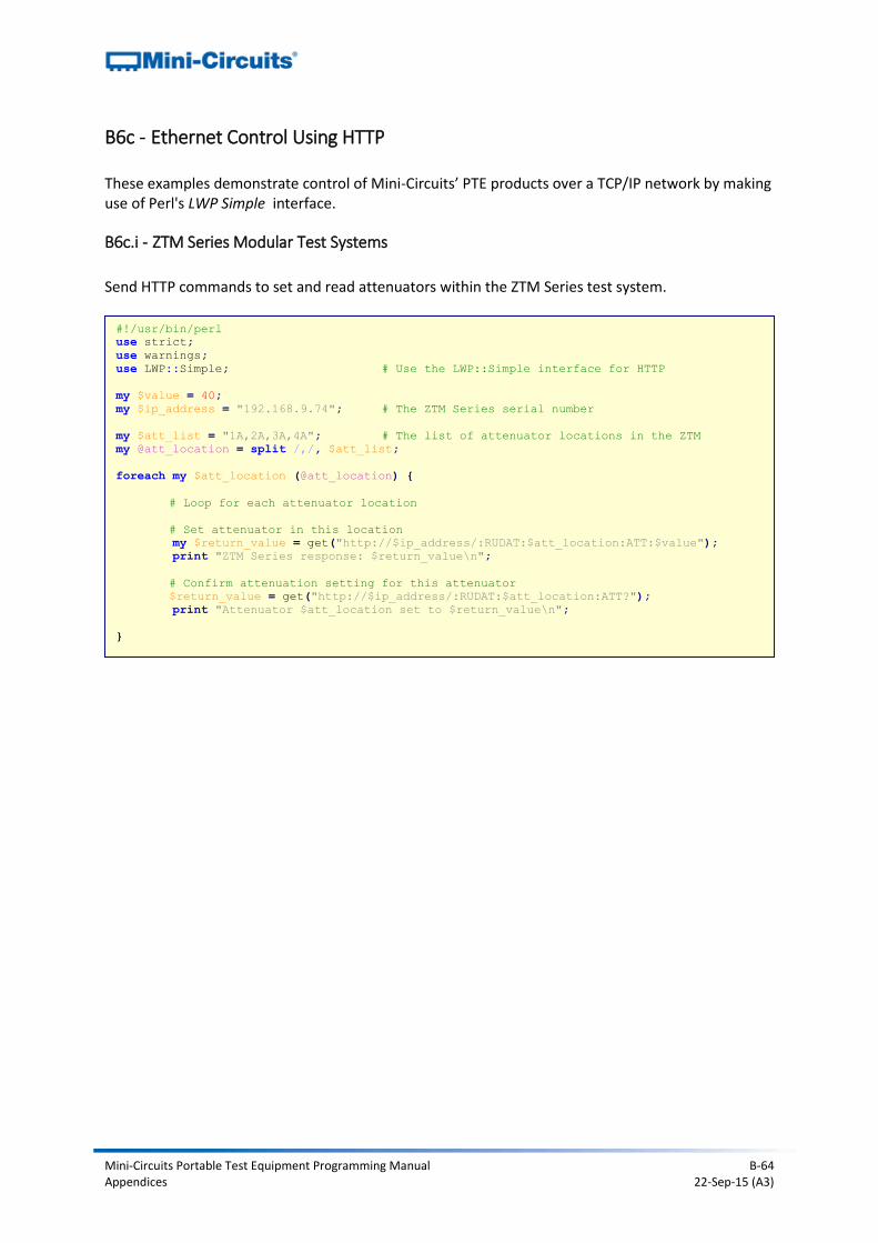
Mini-Circuits Portable Test Equipment Programming Manual B-64 Appendices 22-Sep-15 (A3)
B6c - Ethernet Control Using HTTP These examples demonstrate control of Mini-Circuits’ PTE products over a TCP/IP network by making use of Perl's LWP Simple interface.
B6c.i - ZTM Series Modular Test Systems
Send HTTP commands to set and read attenuators within the ZTM Series test system.
#!/usr/bin/perl
use strict;
use warnings;
use LWP::Simple; # Use the LWP::Simple interface for HTTP
my $value = 40;
my $ip_address = "192.168.9.74"; # The ZTM Series serial number
my $att_list = "1A,2A,3A,4A"; # The list of attenuator locations in the ZTM
my @att_location = split /,/, $att_list;
foreach my $att_location (@att_location) {
# Loop for each attenuator location
# Set attenuator in this location
my $return_value = get("http://$ip_address/:RUDAT:$att_location:ATT:$value");
print "ZTM Series response: $return_value\n";
# Confirm attenuation setting for this attenuator
$return_value = get("http://$ip_address/:RUDAT:$att_location:ATT?");
print "Attenuator $att_location set to $return_value\n";
}
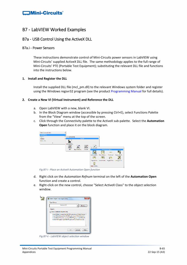
Mini-Circuits Portable Test Equipment Programming Manual B-65 Appendices 22-Sep-15 (A3)
B7 - LabVIEW Worked Examples
B7a - USB Control Using the ActiveX DLL
B7a.i - Power Sensors
These instructions demonstrate control of Mini-Circuits power sensors in LabVIEW using Mini-Circuits’ supplied ActiveX DLL file. The same methodology applies to the full range of Mini-Circuits’ PTE (Portable Test Equipment); substituting the relevant DLL file and functions into the instructions below.
1. Install and Register the DLL
Install the supplied DLL file (mcl_pm.dll) to the relevant Windows system folder and register using the Windows regsvr32 program (see the product Programming Manual for full details).
2. Create a New VI (Virtual Instrument) and Reference the DLL
a. Open LabVIEW with a new, blank VI. b. In the Block Diagram window (accessible by pressing Ctrl+E), select Functions Palette
from the “View” menu at the top of the screen. c. Click through the Connectivity palette to the ActiveX sub-palette. Select the Automation
Open function and place it on the block diagram.
Fig B7-i - Place an ActiveX Automation Open function
d. Right click on the Automation Refnum terminal on the left of the Automation Open function and create a control.
e. Right-click on the new control, choose "Select ActiveX Class" to the object selection window.
Fig B7-ii - LabVIEW object selection window
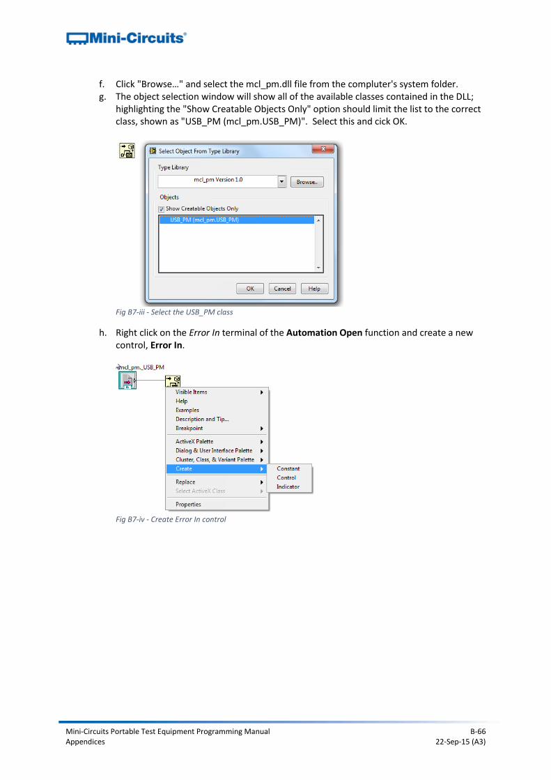
Mini-Circuits Portable Test Equipment Programming Manual B-66 Appendices 22-Sep-15 (A3)
f. Click "Browse…" and select the mcl_pm.dll file from the compluter's system folder. g. The object selection window will show all of the available classes contained in the DLL;
highlighting the "Show Creatable Objects Only" option should limit the list to the correct class, shown as "USB_PM (mcl_pm.USB_PM)". Select this and cick OK.
Fig B7-iii - Select the USB_PM class
h. Right click on the Error In terminal of the Automation Open function and create a new control, Error In.
Fig B7-iv - Create Error In control
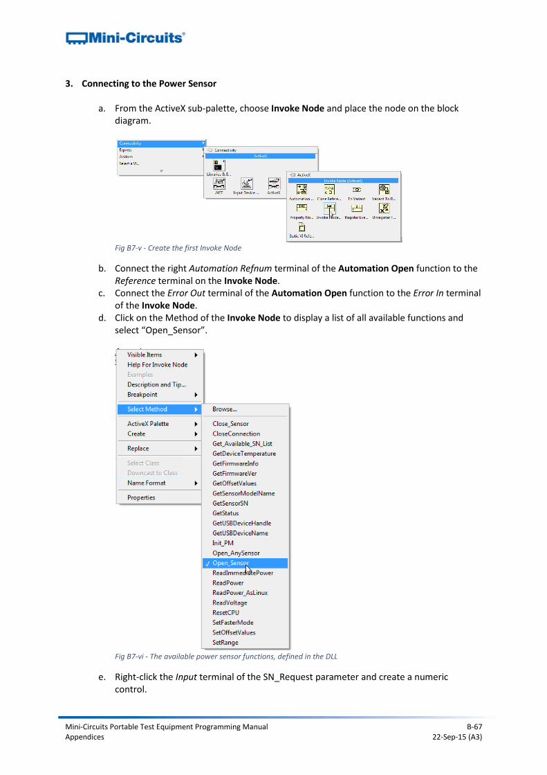
Mini-Circuits Portable Test Equipment Programming Manual B-67 Appendices 22-Sep-15 (A3)
3. Connecting to the Power Sensor
a. From the ActiveX sub-palette, choose Invoke Node and place the node on the block diagram.
Fig B7-v - Create the first Invoke Node
b. Connect the right Automation Refnum terminal of the Automation Open function to the Reference terminal on the Invoke Node.
c. Connect the Error Out terminal of the Automation Open function to the Error In terminal of the Invoke Node.
d. Click on the Method of the Invoke Node to display a list of all available functions and select “Open_Sensor”.
Fig B7-vi - The available power sensor functions, defined in the DLL
e. Right-click the Input terminal of the SN_Request parameter and create a numeric control.
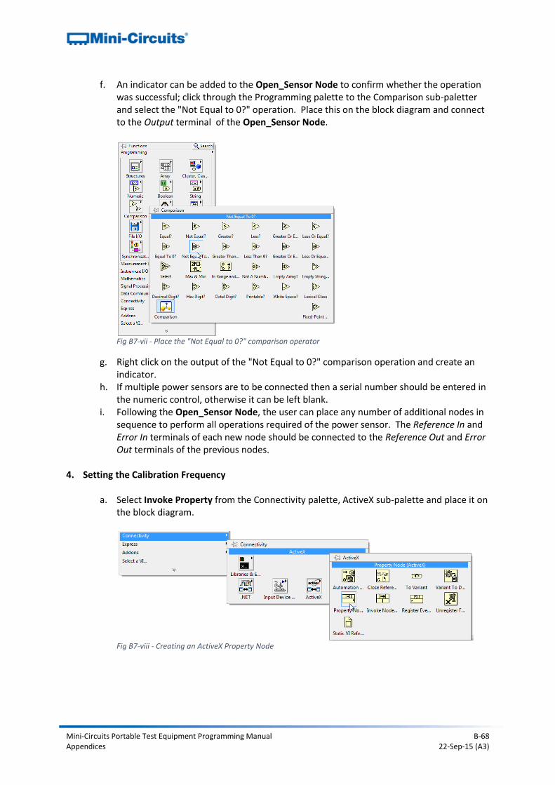
Mini-Circuits Portable Test Equipment Programming Manual B-68 Appendices 22-Sep-15 (A3)
f. An indicator can be added to the Open_Sensor Node to confirm whether the operation was successful; click through the Programming palette to the Comparison sub-paletter and select the "Not Equal to 0?" operation. Place this on the block diagram and connect to the Output terminal of the Open_Sensor Node.
Fig B7-vii - Place the "Not Equal to 0?" comparison operator
g. Right click on the output of the "Not Equal to 0?" comparison operation and create an indicator.
h. If multiple power sensors are to be connected then a serial number should be entered in the numeric control, otherwise it can be left blank.
i. Following the Open_Sensor Node, the user can place any number of additional nodes in sequence to perform all operations required of the power sensor. The Reference In and Error In terminals of each new node should be connected to the Reference Out and Error Out terminals of the previous nodes.
4. Setting the Calibration Frequency
a. Select Invoke Property from the Connectivity palette, ActiveX sub-palette and place it on
the block diagram.
Fig B7-viii - Creating an ActiveX Property Node
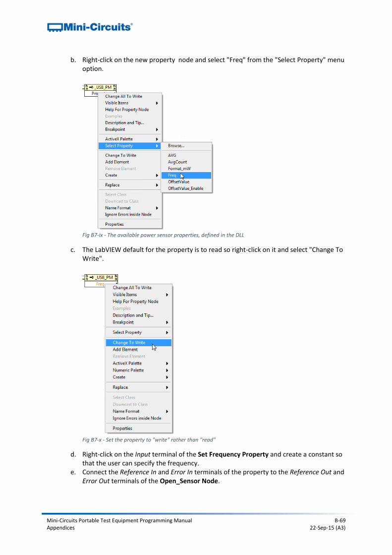
Mini-Circuits Portable Test Equipment Programming Manual B-69 Appendices 22-Sep-15 (A3)
b. Right-click on the new property node and select "Freq" from the "Select Property" menu option.
Fig B7-ix - The available power sensor properties, defined in the DLL
c. The LabVIEW default for the property is to read so right-click on it and select "Change To Write".
Fig B7-x - Set the property to "write" rather than "read"
d. Right-click on the Input terminal of the Set Frequency Property and create a constant so that the user can specify the frequency.
e. Connect the Reference In and Error In terminals of the property to the Reference Out and Error Out terminals of the Open_Sensor Node.
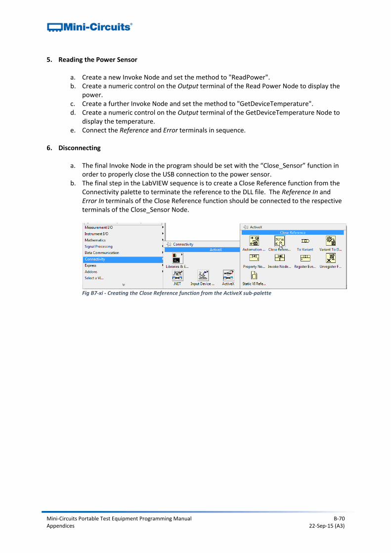
Mini-Circuits Portable Test Equipment Programming Manual B-70 Appendices 22-Sep-15 (A3)
5. Reading the Power Sensor
a. Create a new Invoke Node and set the method to "ReadPower". b. Create a numeric control on the Output terminal of the Read Power Node to display the
power. c. Create a further Invoke Node and set the method to "GetDeviceTemperature". d. Create a numeric control on the Output terminal of the GetDeviceTemperature Node to
display the temperature. e. Connect the Reference and Error terminals in sequence.
6. Disconnecting
a. The final Invoke Node in the program should be set with the “Close_Sensor” function in
order to properly close the USB connection to the power sensor. b. The final step in the LabVIEW sequence is to create a Close Reference function from the
Connectivity palette to terminate the reference to the DLL file. The Reference In and Error In terminals of the Close Reference function should be connected to the respective terminals of the Close_Sensor Node.
Fig B7-xi - Creating the Close Reference function from the ActiveX sub-palette
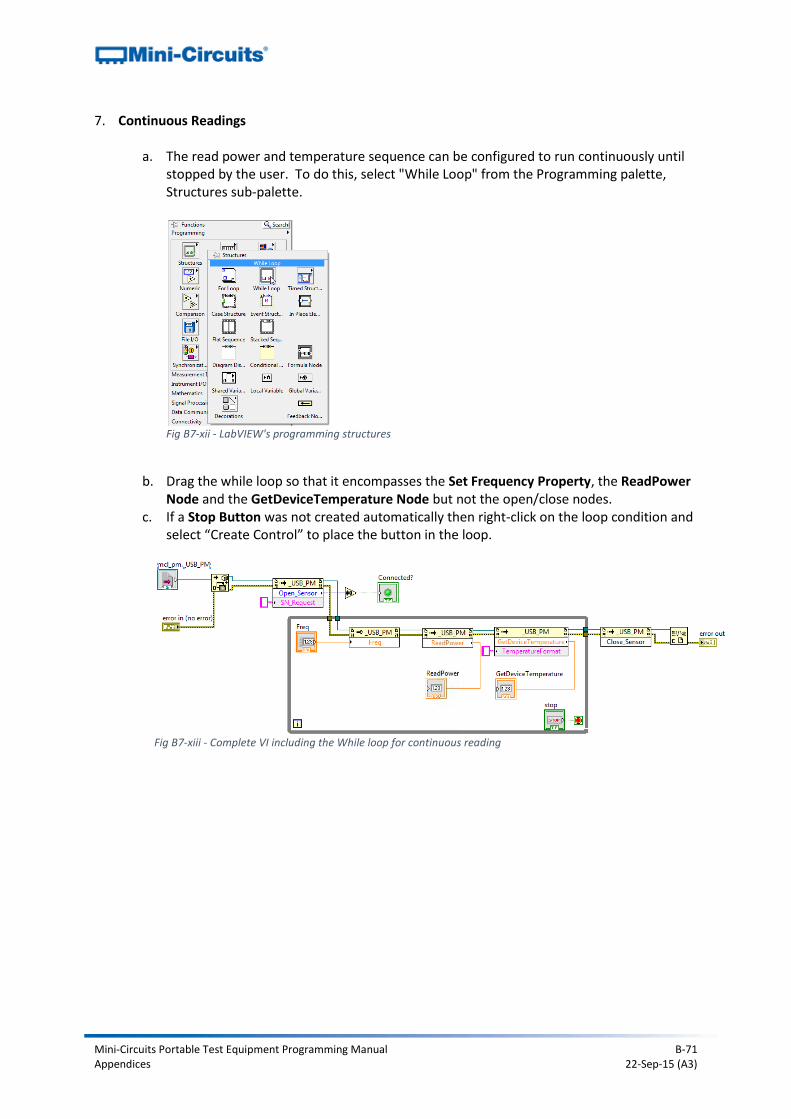
Mini-Circuits Portable Test Equipment Programming Manual B-71 Appendices 22-Sep-15 (A3)
7. Continuous Readings
a. The read power and temperature sequence can be configured to run continuously until stopped by the user. To do this, select "While Loop" from the Programming palette, Structures sub-palette.
Fig B7-xii - LabVIEW's programming structures
b. Drag the while loop so that it encompasses the Set Frequency Property, the ReadPower
Node and the GetDeviceTemperature Node but not the open/close nodes. c. If a Stop Button was not created automatically then right-click on the loop condition and
select “Create Control” to place the button in the loop.
Fig B7-xiii - Complete VI including the While loop for continuous reading
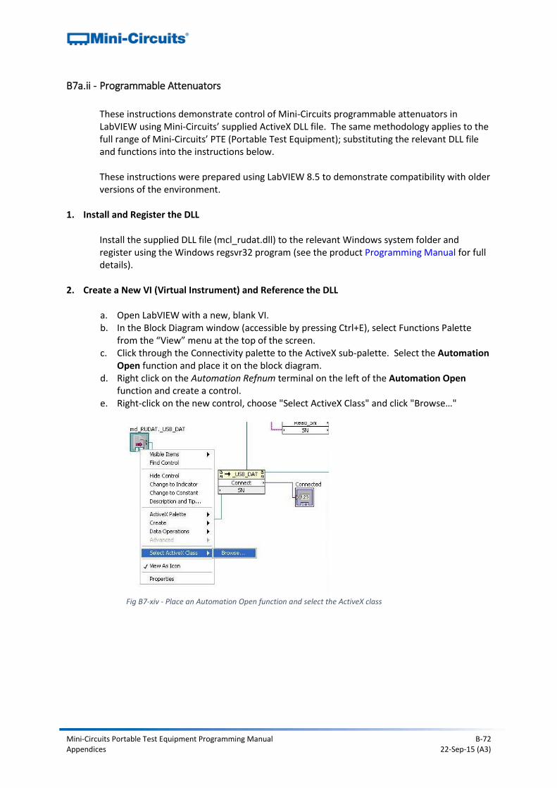
Mini-Circuits Portable Test Equipment Programming Manual B-72 Appendices 22-Sep-15 (A3)
B7a.ii - Programmable Attenuators
These instructions demonstrate control of Mini-Circuits programmable attenuators in LabVIEW using Mini-Circuits’ supplied ActiveX DLL file. The same methodology applies to the full range of Mini-Circuits’ PTE (Portable Test Equipment); substituting the relevant DLL file and functions into the instructions below. These instructions were prepared using LabVIEW 8.5 to demonstrate compatibility with older versions of the environment.
1. Install and Register the DLL
Install the supplied DLL file (mcl_rudat.dll) to the relevant Windows system folder and register using the Windows regsvr32 program (see the product Programming Manual for full details).
2. Create a New VI (Virtual Instrument) and Reference the DLL
a. Open LabVIEW with a new, blank VI. b. In the Block Diagram window (accessible by pressing Ctrl+E), select Functions Palette
from the “View” menu at the top of the screen. c. Click through the Connectivity palette to the ActiveX sub-palette. Select the Automation
Open function and place it on the block diagram. d. Right click on the Automation Refnum terminal on the left of the Automation Open
function and create a control. e. Right-click on the new control, choose "Select ActiveX Class" and click "Browse…"
Fig B7-xiv - Place an Automation Open function and select the ActiveX class
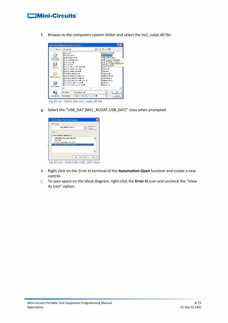
Mini-Circuits Portable Test Equipment Programming Manual B-73 Appendices 22-Sep-15 (A3)
f. Browse to the computers system folder and select the mcl_rudat.dll file.
Fig B7-xv - Select the mcl_rudat.dll file
g. Select the “USB_DAT (MCL_RUDAT.USB_DAT)” class when prompted.
Fig B7-xvi - Select the USB_DAT class
h. Right click on the Error In terminal of the Automation Open function and create a new control.
i. To save space on the block diagram, right-click the Error In icon and uncheck the “View As Icon” option.
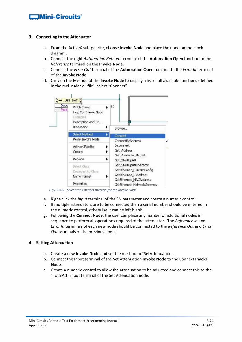
Mini-Circuits Portable Test Equipment Programming Manual B-74 Appendices 22-Sep-15 (A3)
3. Connecting to the Attenuator
a. From the ActiveX sub-palette, choose Invoke Node and place the node on the block diagram.
b. Connect the right Automation Refnum terminal of the Automation Open function to the Reference terminal on the Invoke Node.
c. Connect the Error Out terminal of the Automation Open function to the Error In terminal of the Invoke Node.
d. Click on the Method of the Invoke Node to display a list of all available functions (defined in the mcl_rudat.dll file), select “Connect”.
Fig B7-xvii - Select the Connect method for the Invoke Node
e. Right-click the Input terminal of the SN parameter and create a numeric control. f. If multiple attenuators are to be connected then a serial number should be entered in
the numeric control, otherwise it can be left blank. g. Following the Connect Node, the user can place any number of additional nodes in
sequence to perform all operations required of the attenuator. The Reference In and Error In terminals of each new node should be connected to the Reference Out and Error Out terminals of the previous nodes.
4. Setting Attenuation
a. Create a new Invoke Node and set the method to "SetAttenuation". b. Connect the Input terminal of the Set Attenuation Invoke Node to the Connect Invoke
Node. c. Create a numeric control to allow the attenuation to be adjusted and connect this to the
"TotalAtt" input terminal of the Set Attenuation node.

Mini-Circuits Portable Test Equipment Programming Manual B-75 Appendices 22-Sep-15 (A3)
5. Reading Attenuation
a. Create a new Invoke Node and set the method to "Read_Att". b. Connect the Input terminal of the Read Attenuation Invoke Node to the Connect Invoke
Node. c. Select method Read_att. d. Create a numeric control to display the attenuation and connect it the "CAtt1" Output
terminal of the Read Attenuation node.
6. Disconnecting
a. The final Invoke Node in the program should be set with the “Disconnect” function in order to properly close the connection to the attenuator.
b. The final step in the LabVIEW sequence is to create a Close Reference function from the Connectivity palette to terminate the reference to the DLL file. The Reference In and Error In terminals of the Close Reference function should be connected to the respective terminals of the Disconnect function.
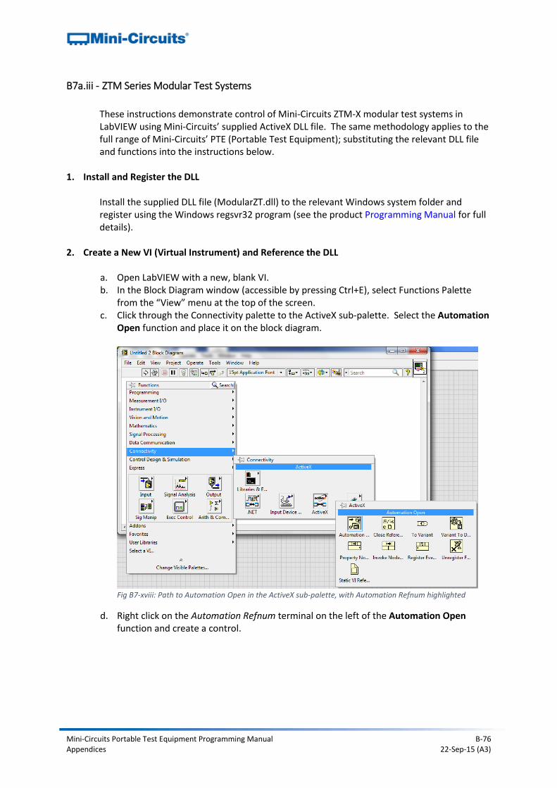
Mini-Circuits Portable Test Equipment Programming Manual B-76 Appendices 22-Sep-15 (A3)
B7a.iii - ZTM Series Modular Test Systems
These instructions demonstrate control of Mini-Circuits ZTM-X modular test systems in LabVIEW using Mini-Circuits’ supplied ActiveX DLL file. The same methodology applies to the full range of Mini-Circuits’ PTE (Portable Test Equipment); substituting the relevant DLL file and functions into the instructions below.
1. Install and Register the DLL
Install the supplied DLL file (ModularZT.dll) to the relevant Windows system folder and register using the Windows regsvr32 program (see the product Programming Manual for full details).
2. Create a New VI (Virtual Instrument) and Reference the DLL
a. Open LabVIEW with a new, blank VI. b. In the Block Diagram window (accessible by pressing Ctrl+E), select Functions Palette
from the “View” menu at the top of the screen. c. Click through the Connectivity palette to the ActiveX sub-palette. Select the Automation
Open function and place it on the block diagram.
d. Right click on the Automation Refnum terminal on the left of the Automation Open
function and create a control.
Fig B7-xviii: Path to Automation Open in the ActiveX sub-palette, with Automation Refnum highlighted
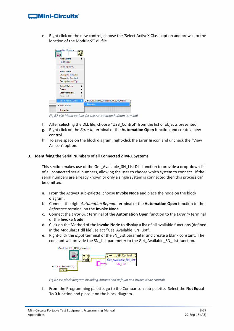
Mini-Circuits Portable Test Equipment Programming Manual B-77 Appendices 22-Sep-15 (A3)
e. Right click on the new control, choose the ‘Select ActiveX Class’ option and browse to the location of the ModularZT.dll file.
f. After selecting the DLL file, choose “USB_Control” from the list of objects presented. g. Right click on the Error In terminal of the Automation Open function and create a new
control. h. To save space on the block diagram, right-click the Error In icon and uncheck the “View
As Icon” option.
3. Identifying the Serial Numbers of all Connected ZTM-X Systems
This section makes use of the Get_Available_SN_List DLL function to provide a drop-down list of all connected serial numbers, allowing the user to choose which system to connect. If the serial numbers are already known or only a single system is connected then this process can be omitted.
a. From the ActiveX sub-palette, choose Invoke Node and place the node on the block
diagram. b. Connect the right Automation Refnum terminal of the Automation Open function to the
Reference terminal on the Invoke Node. c. Connect the Error Out terminal of the Automation Open function to the Error In terminal
of the Invoke Node. d. Click on the Method of the Invoke Node to display a list of all available functions (defined
in the ModularZT.dll file), select “Get_Available_SN_List”. e. Right-click the Input terminal of the SN_List parameter and create a blank constant. The
constant will provide the SN_List parameter to the Get_Available_SN_List function.
f. From the Programming palette, go to the Comparison sub-palette. Select the Not Equal
To 0 function and place it on the block diagram.
Fig B7-xx: Block diagram including Automation Refnum and Invoke Node controls
Fig B7-xix: Menu options for the Automation Refnum terminal
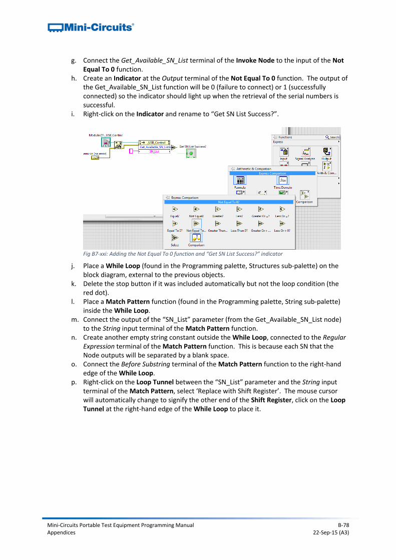
Mini-Circuits Portable Test Equipment Programming Manual B-78 Appendices 22-Sep-15 (A3)
g. Connect the Get_Available_SN_List terminal of the Invoke Node to the input of the Not Equal To 0 function.
h. Create an Indicator at the Output terminal of the Not Equal To 0 function. The output of the Get_Available_SN_List function will be 0 (failure to connect) or 1 (successfully connected) so the indicator should light up when the retrieval of the serial numbers is successful.
i. Right-click on the Indicator and rename to “Get SN List Success?”.
j. Place a While Loop (found in the Programming palette, Structures sub-palette) on the
block diagram, external to the previous objects. k. Delete the stop button if it was included automatically but not the loop condition (the
red dot). l. Place a Match Pattern function (found in the Programming palette, String sub-palette)
inside the While Loop. m. Connect the output of the “SN_List” parameter (from the Get_Available_SN_List node)
to the String input terminal of the Match Pattern function. n. Create another empty string constant outside the While Loop, connected to the Regular
Expression terminal of the Match Pattern function. This is because each SN that the Node outputs will be separated by a blank space.
o. Connect the Before Substring terminal of the Match Pattern function to the right-hand edge of the While Loop.
p. Right-click on the Loop Tunnel between the “SN_List” parameter and the String input terminal of the Match Pattern, select ‘Replace with Shift Register’. The mouse cursor will automatically change to signify the other end of the Shift Register, click on the Loop Tunnel at the right-hand edge of the While Loop to place it.
Fig B7-xxi: Adding the Not Equal To 0 function and “Get SN List Success?” indicator
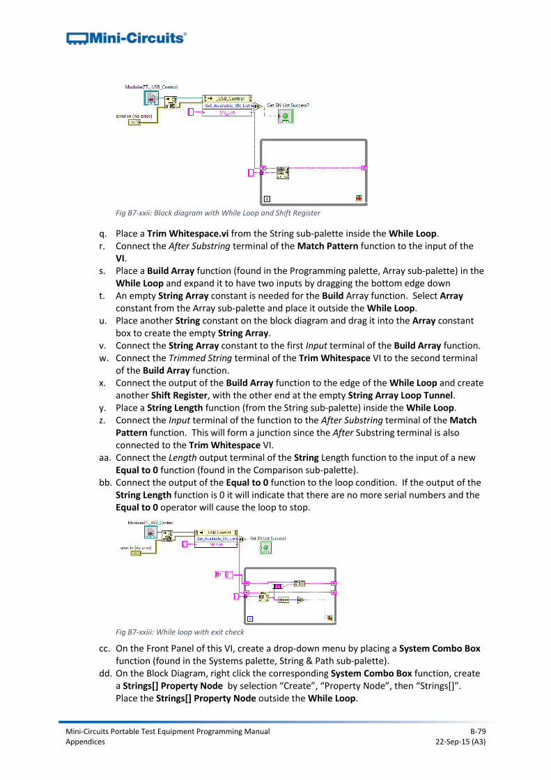
Mini-Circuits Portable Test Equipment Programming Manual B-79 Appendices 22-Sep-15 (A3)
q. Place a Trim Whitespace.vi from the String sub-palette inside the While Loop. r. Connect the After Substring terminal of the Match Pattern function to the input of the
VI. s. Place a Build Array function (found in the Programming palette, Array sub-palette) in the
While Loop and expand it to have two inputs by dragging the bottom edge down t. An empty String Array constant is needed for the Build Array function. Select Array
constant from the Array sub-palette and place it outside the While Loop. u. Place another String constant on the block diagram and drag it into the Array constant
box to create the empty String Array. v. Connect the String Array constant to the first Input terminal of the Build Array function. w. Connect the Trimmed String terminal of the Trim Whitespace VI to the second terminal
of the Build Array function. x. Connect the output of the Build Array function to the edge of the While Loop and create
another Shift Register, with the other end at the empty String Array Loop Tunnel. y. Place a String Length function (from the String sub-palette) inside the While Loop. z. Connect the Input terminal of the function to the After Substring terminal of the Match
Pattern function. This will form a junction since the After Substring terminal is also connected to the Trim Whitespace VI.
aa. Connect the Length output terminal of the String Length function to the input of a new Equal to 0 function (found in the Comparison sub-palette).
bb. Connect the output of the Equal to 0 function to the loop condition. If the output of the String Length function is 0 it will indicate that there are no more serial numbers and the Equal to 0 operator will cause the loop to stop.
cc. On the Front Panel of this VI, create a drop-down menu by placing a System Combo Box
function (found in the Systems palette, String & Path sub-palette). dd. On the Block Diagram, right click the corresponding System Combo Box function, create
a Strings[] Property Node by selection “Create”, “Property Node”, then “Strings[]”. Place the Strings[] Property Node outside the While Loop.
Fig B7-xxii: Block diagram with While Loop and Shift Register
Fig B7-xxiii: While loop with exit check
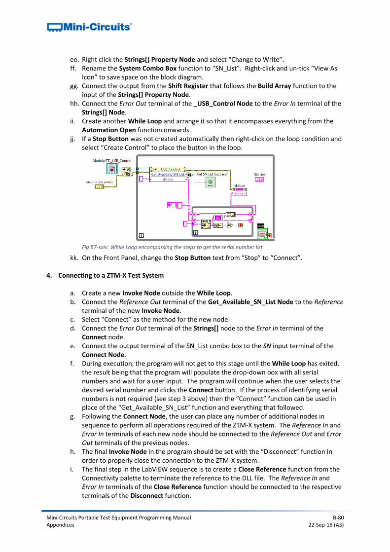
Mini-Circuits Portable Test Equipment Programming Manual B-80 Appendices 22-Sep-15 (A3)
ee. Right click the Strings[] Property Node and select “Change to Write”. ff. Rename the System Combo Box function to “SN_List”. Right-click and un-tick “View As
Icon” to save space on the block diagram. gg. Connect the output from the Shift Register that follows the Build Array function to the
input of the Strings[] Property Node. hh. Connect the Error Out terminal of the _USB_Control Node to the Error In terminal of the
Strings[] Node. ii. Create another While Loop and arrange it so that it encompasses everything from the
Automation Open function onwards. jj. If a Stop Button was not created automatically then right-click on the loop condition and
select “Create Control” to place the button in the loop.
kk. On the Front Panel, change the Stop Button text from “Stop” to “Connect”.
4. Connecting to a ZTM-X Test System
a. Create a new Invoke Node outside the While Loop. b. Connect the Reference Out terminal of the Get_Available_SN_List Node to the Reference
terminal of the new Invoke Node. c. Select “Connect” as the method for the new node. d. Connect the Error Out terminal of the Strings[] node to the Error In terminal of the
Connect node. e. Connect the output terminal of the SN_List combo box to the SN input terminal of the
Connect Node. f. During execution, the program will not get to this stage until the While Loop has exited,
the result being that the program will populate the drop-down box with all serial numbers and wait for a user input. The program will continue when the user selects the desired serial number and clicks the Connect button. If the process of identifying serial numbers is not required (see step 3 above) then the “Connect” function can be used in place of the “Get_Available_SN_List” function and everything that followed.
g. Following the Connect Node, the user can place any number of additional nodes in sequence to perform all operations required of the ZTM-X system. The Reference In and Error In terminals of each new node should be connected to the Reference Out and Error Out terminals of the previous nodes.
h. The final Invoke Node in the program should be set with the “Disconnect” function in order to properly close the connection to the ZTM-X system.
i. The final step in the LabVIEW sequence is to create a Close Reference function from the Connectivity palette to terminate the reference to the DLL file. The Reference In and Error In terminals of the Close Reference function should be connected to the respective terminals of the Disconnect function.
Fig B7-xxiv: While Loop encompassing the steps to get the serial number list
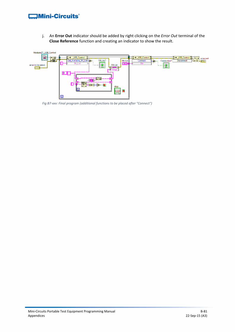
Mini-Circuits Portable Test Equipment Programming Manual B-81 Appendices 22-Sep-15 (A3)
j. An Error Out indicator should be added by right clicking on the Error Out terminal of the Close Reference function and creating an indicator to show the result.
Fig B7-xxv: Final program (additional functions to be placed after "Connect")
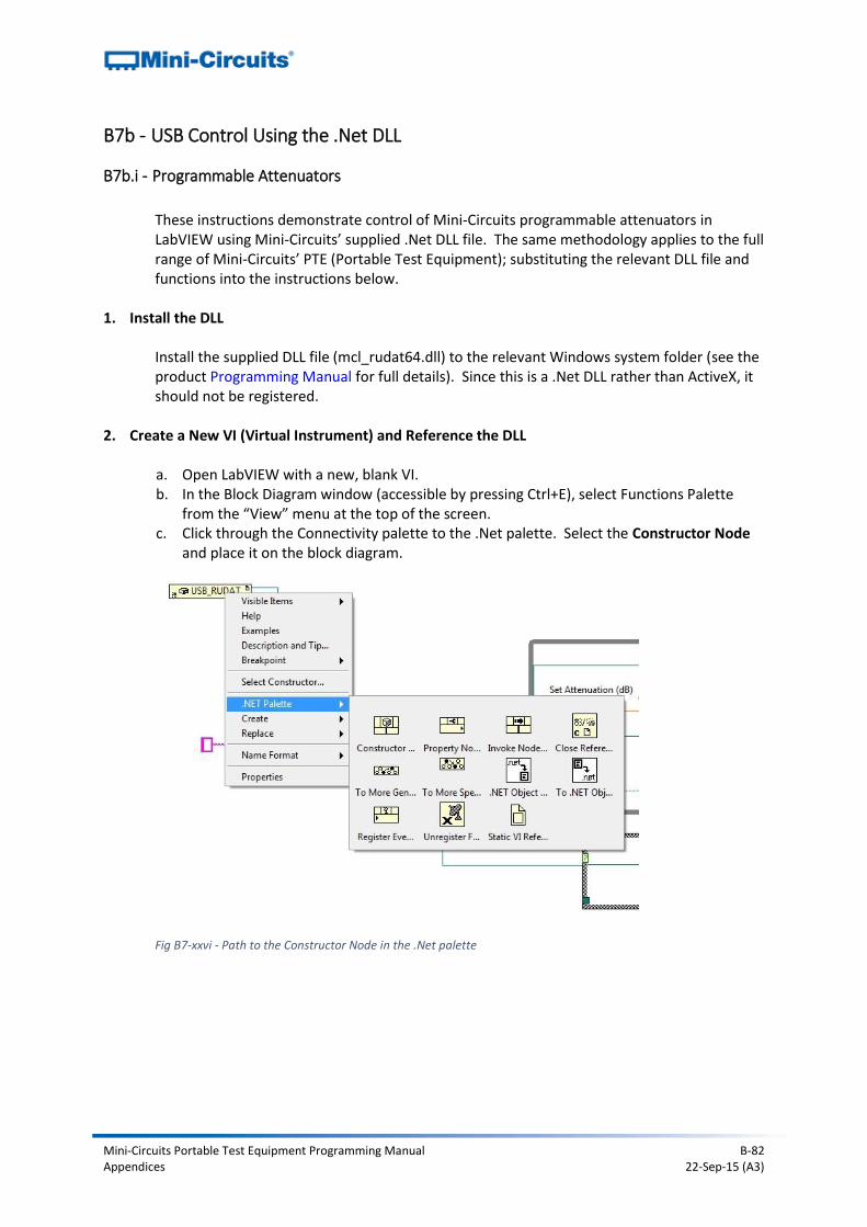
Mini-Circuits Portable Test Equipment Programming Manual B-82 Appendices 22-Sep-15 (A3)
B7b - USB Control Using the .Net DLL
B7b.i - Programmable Attenuators
These instructions demonstrate control of Mini-Circuits programmable attenuators in LabVIEW using Mini-Circuits’ supplied .Net DLL file. The same methodology applies to the full range of Mini-Circuits’ PTE (Portable Test Equipment); substituting the relevant DLL file and functions into the instructions below.
1. Install the DLL
Install the supplied DLL file (mcl_rudat64.dll) to the relevant Windows system folder (see the product Programming Manual for full details). Since this is a .Net DLL rather than ActiveX, it should not be registered.
2. Create a New VI (Virtual Instrument) and Reference the DLL
a. Open LabVIEW with a new, blank VI. b. In the Block Diagram window (accessible by pressing Ctrl+E), select Functions Palette
from the “View” menu at the top of the screen. c. Click through the Connectivity palette to the .Net palette. Select the Constructor Node
and place it on the block diagram.
Fig B7-xxvi - Path to the Constructor Node in the .Net palette
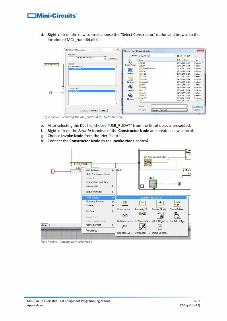
Mini-Circuits Portable Test Equipment Programming Manual B-83 Appendices 22-Sep-15 (A3)
d. Right-click on the new control, choose the "Select Constructor" option and browse to the location of MCL_rudat64.dll file.
Fig B7-xxvii - Selecting the mcl_rudat64.dll .Net assembly
e. After selecting the DLL file, choose “USB_RUDAT” from the list of objects presented. f. Right-click on the Error In terminal of the Constructor Node and create a new control. g. Choose Invoke Node from the .Net Palette. h. Connect the Constructor Node to the Invoke Node control.
Fig B7-xxviii - Placing an Invoke Node
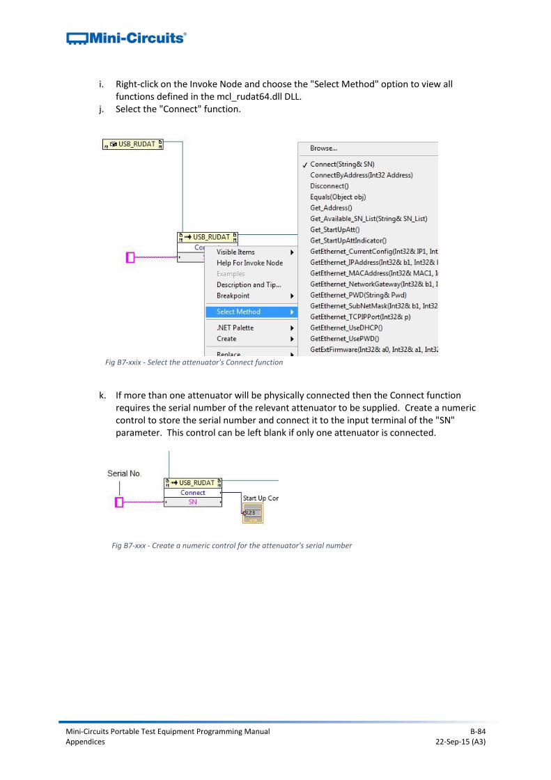
Mini-Circuits Portable Test Equipment Programming Manual B-84 Appendices 22-Sep-15 (A3)
i. Right-click on the Invoke Node and choose the "Select Method" option to view all functions defined in the mcl_rudat64.dll DLL.
j. Select the "Connect" function.
Fig B7-xxix - Select the attenuator's Connect function
k. If more than one attenuator will be physically connected then the Connect function
requires the serial number of the relevant attenuator to be supplied. Create a numeric control to store the serial number and connect it to the input terminal of the "SN" parameter. This control can be left blank if only one attenuator is connected.
Fig B7-xxx - Create a numeric control for the attenuator's serial number
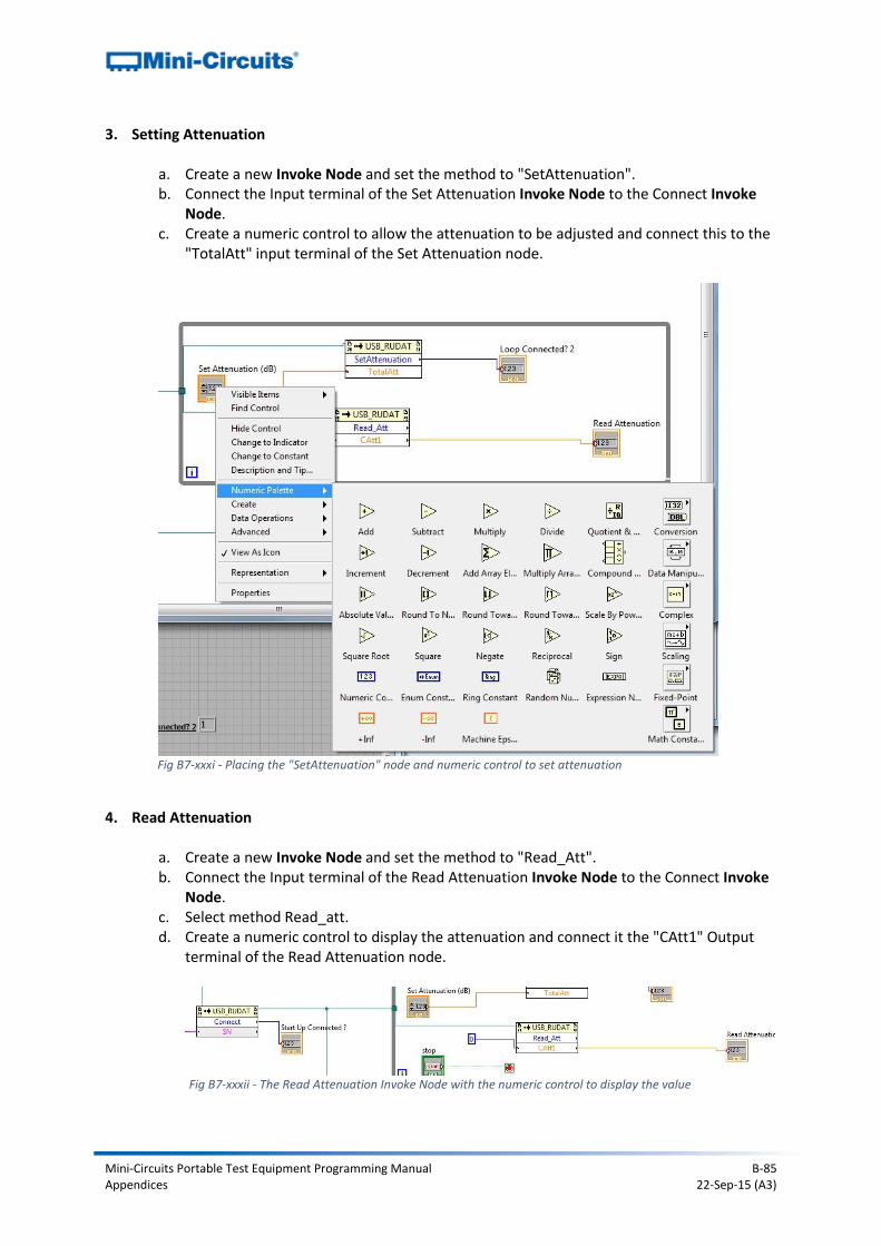
Mini-Circuits Portable Test Equipment Programming Manual B-85 Appendices 22-Sep-15 (A3)
3. Setting Attenuation
a. Create a new Invoke Node and set the method to "SetAttenuation". b. Connect the Input terminal of the Set Attenuation Invoke Node to the Connect Invoke
Node. c. Create a numeric control to allow the attenuation to be adjusted and connect this to the
"TotalAtt" input terminal of the Set Attenuation node.
Fig B7-xxxi - Placing the "SetAttenuation" node and numeric control to set attenuation
4. Read Attenuation
a. Create a new Invoke Node and set the method to "Read_Att". b. Connect the Input terminal of the Read Attenuation Invoke Node to the Connect Invoke
Node. c. Select method Read_att. d. Create a numeric control to display the attenuation and connect it the "CAtt1" Output
terminal of the Read Attenuation node.
Fig B7-xxxii - The Read Attenuation Invoke Node with the numeric control to display the value
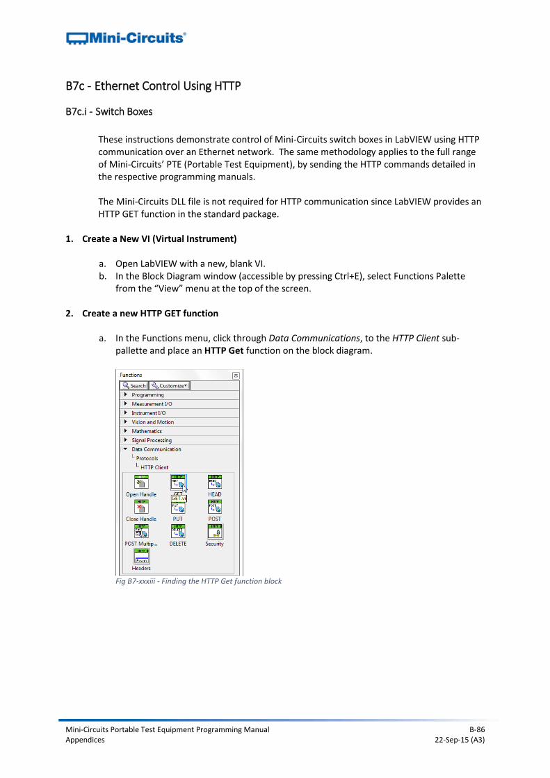
Mini-Circuits Portable Test Equipment Programming Manual B-86 Appendices 22-Sep-15 (A3)
B7c - Ethernet Control Using HTTP
B7c.i - Switch Boxes
These instructions demonstrate control of Mini-Circuits switch boxes in LabVIEW using HTTP communication over an Ethernet network. The same methodology applies to the full range of Mini-Circuits’ PTE (Portable Test Equipment), by sending the HTTP commands detailed in the respective programming manuals. The Mini-Circuits DLL file is not required for HTTP communication since LabVIEW provides an HTTP GET function in the standard package.
1. Create a New VI (Virtual Instrument)
a. Open LabVIEW with a new, blank VI. b. In the Block Diagram window (accessible by pressing Ctrl+E), select Functions Palette
from the “View” menu at the top of the screen.
2. Create a new HTTP GET function
a. In the Functions menu, click through Data Communications, to the HTTP Client sub-pallette and place an HTTP Get function on the block diagram.
Fig B7-xxxiii - Finding the HTTP Get function block
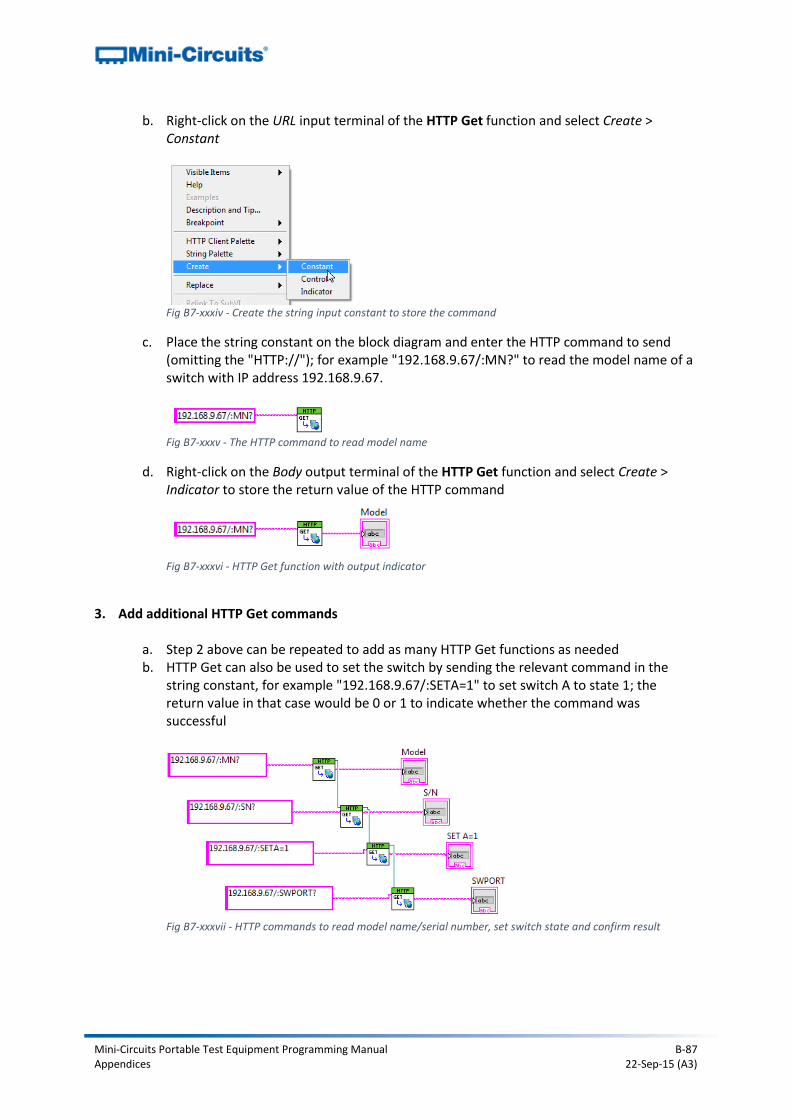
Mini-Circuits Portable Test Equipment Programming Manual B-87 Appendices 22-Sep-15 (A3)
b. Right-click on the URL input terminal of the HTTP Get function and select Create > Constant
Fig B7-xxxiv - Create the string input constant to store the command
c. Place the string constant on the block diagram and enter the HTTP command to send (omitting the "HTTP://"); for example "192.168.9.67/:MN?" to read the model name of a switch with IP address 192.168.9.67.
Fig B7-xxxv - The HTTP command to read model name
d. Right-click on the Body output terminal of the HTTP Get function and select Create > Indicator to store the return value of the HTTP command
Fig B7-xxxvi - HTTP Get function with output indicator
3. Add additional HTTP Get commands
a. Step 2 above can be repeated to add as many HTTP Get functions as needed b. HTTP Get can also be used to set the switch by sending the relevant command in the
string constant, for example "192.168.9.67/:SETA=1" to set switch A to state 1; the return value in that case would be 0 or 1 to indicate whether the command was successful
Fig B7-xxxvii - HTTP commands to read model name/serial number, set switch state and confirm result
Mini-Circuits Portable Test Equipment Programming Manual B-88 Appendices 22-Sep-15 (A3)
B8 - MATLAB Worked Examples
B8a - USB Control Using the ActiveX DLL
B8a.i - Switch Boxes
Overview
These instructions demonstrate how to control any Mini-Circuits USB switch box in MatLab using the ActiveX DLL. The same methodology applies for the full Mini-Circuits range of PTE (Portable Test Equipment); substituting the relevant DLL file and functions into the instructions below.
1. Install and Register the DLL
Install the switch box’s DLL file (mcl_rf_switch_controller.dll) to the relevant Windows system folder and register using the Windows regsvr32 program (see the product Programming Manual for full details).
2. Declare the DLL Class
Use the actxserver function in Matlab to declare the DLL class and assign it to an object that will represent the switch. The object can be given any name (eg: “sw1”) as long as it complies with the naming rules in MatLab. This process can be repeated in order to control multiple switch boxes simultaneously with MatLab. For example, to control two switch boxes that are to be referred to as “sw1” and “sw2”, the following 2 commands would be needed: >> sw1 = actxserver('MCL_RF_Switch_Controller.USB_RF_Switch')
>> sw2 = actxserver('MCL_RF_Switch_Controller.USB_RF_Switch')
The program should respond with: sw1 = COM.MCL__RF__Switch__Controller_USB__RF__Switch
sw2 = COM.MCL__RF__Switch__Controller_USB__RF__Switch
3. Connect the Switch Boxes by Serial Number
The physical switch hardware must now be assigned to the software switch objects just
created (sw1 and sw2). Use the “Connect” function (defined in the switch DLL) with the hardware serial numbers. In this example, the 2 switch boxes have serial numbers 11308230011 and 11308230015. MatLab will respond with “ans = 1” on success. >> sw1.Connect('11308230011')
ans = 1
>> sw2.Connect('11308230015')
ans = 1
Mini-Circuits Portable Test Equipment Programming Manual B-89 Appendices 22-Sep-15 (A3)
4. Send Commands The 2 switch boxes are now configured for use and can be commanded as required. Use the “sw1” or “sw2” name before each command sent in order to address the correct hardware. A full explanation of the available commands is included in the switch chapter of the Programming Manual at http://www.minicircuits.com/softwaredownload/Prog_Manual-2-Switch.pdf but some brief examples are below: 1) Set sw1 to state 4 and sw2 to state 0: >> sw1.Set_SwitchesPort(char(4)) ans = 1 >> sw2.Set_SwitchesPort(char(0)) ans = 1 2) Confirm switch states (first define 2 variables “Status” and “SwState” which can accept the return values of the DLL function): >> [Status,SwState]=sw1.GetSwitchesStatus(SwState) ans = 1 >> SwState ans = 4 >> [Status,SwState]=sw21.GetSwitchesStatus(SwState) ans = 1 >> SwState ans = 0
5. Disconnect the Switch Boxes The switch boxes should be disconnected on completion of the switching routine using the “Disconnect” function in the DLL: >> sw1.Disconnect >> sw2.Disconnect
6. Display all Commands If required, MatLab can print the full list of available commands to the console using the “invoke” command: >> sw1.Invoke GetConnectionStatus = Variant GetConnectionStatus(handle) GetDeviceTemperature = [single, int16] GetDeviceTemperature(handle, int16) Get_Available_SN_List = [int16, string] Get_Available_SN_List(handle, string) Get_Available_Address_List = [int16, string] Get_Available_Address_List(handle, string) … …
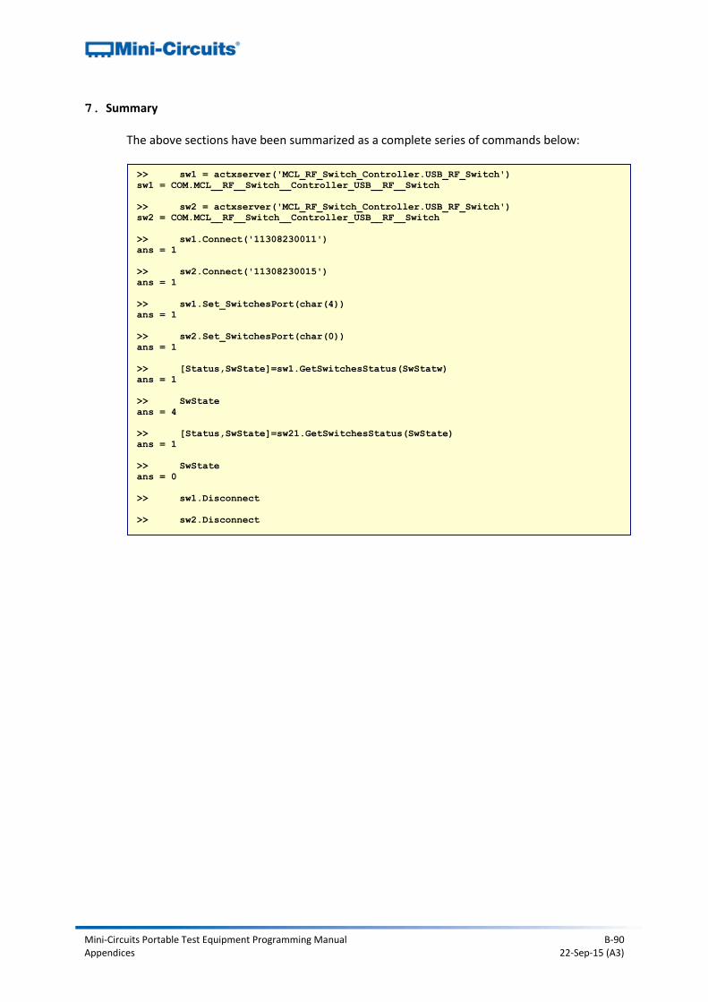
Mini-Circuits Portable Test Equipment Programming Manual B-90 Appendices 22-Sep-15 (A3)
7. Summary The above sections have been summarized as a complete series of commands below:
>> sw1 = actxserver('MCL_RF_Switch_Controller.USB_RF_Switch')
sw1 = COM.MCL__RF__Switch__Controller_USB__RF__Switch
>> sw2 = actxserver('MCL_RF_Switch_Controller.USB_RF_Switch')
sw2 = COM.MCL__RF__Switch__Controller_USB__RF__Switch
>> sw1.Connect('11308230011')
ans = 1
>> sw2.Connect('11308230015')
ans = 1
>> sw1.Set_SwitchesPort(char(4))
ans = 1
>> sw2.Set_SwitchesPort(char(0))
ans = 1
>> [Status,SwState]=sw1.GetSwitchesStatus(SwStatw)
ans = 1
>> SwState
ans = 4
>> [Status,SwState]=sw21.GetSwitchesStatus(SwState)
ans = 1
>> SwState
ans = 0
>> sw1.Disconnect
>> sw2.Disconnect
Mini-Circuits Portable Test Equipment Programming Manual B-91 Appendices 22-Sep-15 (A3)
B8b - USB Control Using the .Net DLL
B8b.i - Switch Boxes
Overview
These instructions demonstrate how to control any Mini-Circuits USB switch box in MatLab using the .Net DLL. The same methodology applies for the full Mini-Circuits range of PTE (Portable Test Equipment); substituting the relevant DLL file and functions into the instructions below.
1. Install the DLL Install the switch's DLL file (mcl_rf_switch_controller64.dll) to the relevant Windows system folder (usually \sysWOW64\); there is no need to register .Net DLLs.
2. Provide the Location of the DLL File to MatLab
Use the NET.addAssembly function in Matlab to provide a handle to the DLL (so that MatLab can locate it). The handle can be given any name that complies with MatLab’s naming rules (eg: “MCL_SW”). This step only needs to be taken once, even if multiple switches are to be commanded simultaneously. >>
MCL_SW=NET.addAssembly('C:\Windows\SysWOW64\mcl_RF_Switch_Controller6
4.dll')
MatLab will acknowledge the command with some generic information about .Net assemblies.
3. Reference the .NET assembly Declare an object that will represent the switch and then assign it to the USB_RF_SwitchBox class defined in the DLL. This process can be repeated in order to control multiple switch boxes simultaneously with MatLab. For example, to control two switch boxes that are to be referred to as “sw1” and “sw2”, the following 2 commands would be needed: >> sw1 = mcl_RF_Switch_Controller64.USB_RF_SwitchBox
>> sw2 = mcl_RF_Switch_Controller64.USB_RF_SwitchBox
4. Connect the Switch Boxes by Serial Number
The physical switch box hardware must now be assigned to the software objects just created (sw1 and sw2). Use the “Connect” function (defined in the DLL) with the hardware serial numbers. In this example, the 2 switch boxes have serial numbers 11504210025 and 11504210026. MatLab will respond with “ans = 1” on success. >> sw1.Connect('11504210025')
ans = 1
>> sw2.Connect('11504210026')
ans = 1

Mini-Circuits Portable Test Equipment Programming Manual B-92 Appendices 22-Sep-15 (A3)
5. Send Commands The 2 switch boxes are now configured for use and can be commanded as required. Use the “sw1” or “sw2” name before each command sent in order to address the correct hardware. A full explanation of the available commands is included in the relevant chapter of the Programming Manual at http://www.minicircuits.com/softwaredownload/Prog_Manual-2-Switch.pdf but some brief examples are below: 1) Assume switch box 1 and 2 are both model RC-2SP6T-A18 (dual switch boxes): >> sw1.Set_2SP6T_COM_To(3, 0)
ans = 1
>> sw2.Set_2SP6T_COM_To(6, 6)
ans = 1
The above commands set the following switch states:
Switch box 1 o Switch A = state 3 (Com port connected to port 3) o Switch B = state 0 (all ports disconnected)
Switch box 2 o Switch A = state 6 (Com port connected to port 6) o Switch B = state 6 (Com port connected to port 6)
2) Confirm the above switch states were set using the below commands: >> sw1.Get_2SP6T_State('A')
ans = 3
>> sw1.Get_2SP6T_State('B')
ans = 0
>> sw2.Get_2SP6T_State('A')
ans = 6
>> sw2.Get_2SP6T_State('B')
ans = 6
6. Disconnect the Switch Boxes
The switch boxes should be disconnected on completion of the switching routine using the “Disconnect” function in the DLL: >> sw1.Disconnect
>> sw2.Disconnect
Mini-Circuits Portable Test Equipment Programming Manual B-93 Appendices 22-Sep-15 (A3)
7. Summary The above sections have been summarized as a complete series of commands below:
>> MCL_SW=NET.addAssembly('C:\Windows\SysWOW64\mcl_rf_switch_controller64.dll')
>> sw1 = mcl_rf_switch_controller64.USB_RF_SwitchBox
sw1 =
mcl_RF_Switch_Controller64.USB_RF_SwitchBox handle with no properties.
Package: mcl_RF_Switch_Controller64
Methods, Events, Superclasses
>> sw2 = mcl_rf_switch_controller64.USB_RF_SwitchBox
sw2 =
mcl_RF_Switch_Controller64.USB_RF_SwitchBox handle with no properties.
Package: mcl_RF_Switch_Controller64
Methods, Events, Superclasses
>> sw1.Set_2SP6T_COM_To(3, 0)
ans = 1
>> sw2.Set_2SP6T_COM_To(6, 6)
ans = 1
>> sw1.Get_2SP6T_State('A')
ans = 3
>> sw1.Get_2SP6T_State('B')
ans = 0
>> sw2.Get_2SP6T_State('A')
ans = 6
>> sw2.Get_2SP6T_State('B')
ans = 6
>> sw1.Disconnect
>> sw2.Disconnect
Mini-Circuits Portable Test Equipment Programming Manual B-94 Appendices 22-Sep-15 (A3)
B8b.ii - IO Control Boxes
Overview
These instructions demonstrate how to control any Mini-Circuits USB Input/Output Control box in MatLab using the .Net DLL. The same methodology applies for the full Mini-Circuits range of PTE (Portable Test Equipment); substituting the relevant DLL file and functions into the instructions below.
1. Install the DLL Install the control box’s DLL file (MCL_USB_To_IO_64.dll) to the relevant Windows system folder (usually \sysWOW64\); there is no need to register .Net DLLs.
2. Provide the Location of the DLL File to MatLab
Use the NET.addAssembly function in Matlab to provide a handle to the DLL (so that MatLab can locate it). The handle can be given any name that complies with MatLab’s naming rules (eg: “USB_IO”). This step only needs to be taken once, even if multiple control boxes are to be commanded simultaneously. >> USB_IO=NET.addAssembly('C:\Windows\SysWOW64\mcl_USB_To_IO_64.dll')
MatLab will acknowledge the command with some generic information about .Net assemblies.
3. Reference the .NET assembly Declare an object that will represent the control box and then assign it to the USB_IO class defined in the DLL. This process can be repeated in order to control multiple control boxes simultaneously with MatLab. For example, to control two input/output control boxes that are to be referred to as “io1” and “io2”, the following 2 commands would be needed: >> io1 = mcl_USB_To_IO_64.USB_IO
>> io2 = mcl_USB_To_IO_64.USB_IO
4. Connect the Control Boxes by Serial Number
The physical control box hardware must now be assigned to the software objects just created (io1 and io2). Use the “Connect” function (defined in the DLL) with the hardware serial numbers. In this example, the 2 control boxes have serial numbers 11308230011 and 11308230015. MatLab will respond with “ans = 1” on success. >> io1.Connect('11308230011')
ans = 1
>> io2.Connect('11308230015')
ans = 1
Mini-Circuits Portable Test Equipment Programming Manual B-95 Appendices 22-Sep-15 (A3)
5. Send Commands The 2 control boxes are now configured for use and can be commanded as required. Use the “io1” or “io2” name before each command sent in order to address the correct hardware. A full explanation of the available commands is included in the relevant chapter of the Programming Manual at http://www.minicircuits.com/softwaredownload/Prog_Manual-7-IO_Control.pdf but some brief examples are below: 1) Set the “byte A” output of io1 to state 52 and io2 to 48: >> io1.Set_ByteA(52)
ans = 1
>> io2.Set_ByteA(48)
ans = 1
2) Confirm the output states (first define 2 variables, arbitrarily called “Status” and “ioValue”, which can accept the return values of the DLL function): >> [Status,ioValue]=io1.ReadByteA(ioValue)
ans = 1
>> ioValue
ans = 52
>> [Status,ioValue]=io2.ReadByteA(ioValue)
ans = 1
>> ioValue
ans = 48
6. Disconnect the Control Boxes
The control boxes should be disconnected on completion of the routine using the “Disconnect” function in the DLL: >> io1.Disconnect
>> io2.Disconnect
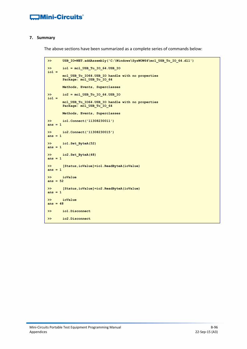
Mini-Circuits Portable Test Equipment Programming Manual B-96 Appendices 22-Sep-15 (A3)
7. Summary The above sections have been summarized as a complete series of commands below: >> USB_IO=NET.addAssembly('C:\Windows\SysWOW64\mcl_USB_To_IO_64.dll')
>> io1 = mcl_USB_To_IO_64.USB_IO
io1 =
mcl_USB_To_IO64.USB_IO handle with no properties
Package: mcl_USB_To_IO_64
Methods, Events, Superclasses
>> io2 = mcl_USB_To_IO_64.USB_IO
io1 =
mcl_USB_To_IO64.USB_IO handle with no properties
Package: mcl_USB_To_IO_64
Methods, Events, Superclasses
>> io1.Connect('11308230011')
ans = 1
>> io2.Connect('11308230015')
ans = 1
>> io1.Set_ByteA(52)
ans = 1
>> io2.Set_ByteA(48)
ans = 1
>> [Status,ioValue]=io1.ReadByteA(ioValue)
ans = 1
>> ioValue
ans = 52
>> [Status,ioValue]=io2.ReadByteA(ioValue)
ans = 1
>> ioValue
ans = 48
>> io1.Disconnect
>> io2.Disconnect
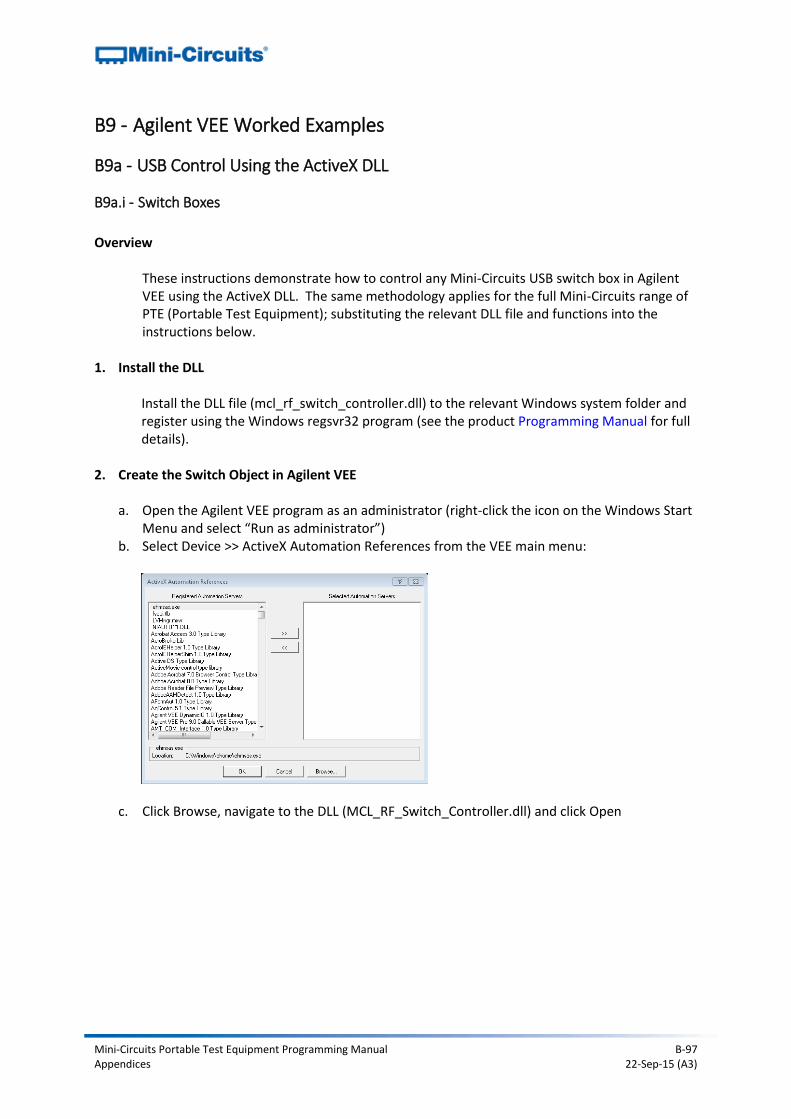
Mini-Circuits Portable Test Equipment Programming Manual B-97 Appendices 22-Sep-15 (A3)
B9 - Agilent VEE Worked Examples
B9a - USB Control Using the ActiveX DLL
B9a.i - Switch Boxes
Overview
These instructions demonstrate how to control any Mini-Circuits USB switch box in Agilent VEE using the ActiveX DLL. The same methodology applies for the full Mini-Circuits range of PTE (Portable Test Equipment); substituting the relevant DLL file and functions into the instructions below.
1. Install the DLL Install the DLL file (mcl_rf_switch_controller.dll) to the relevant Windows system folder and register using the Windows regsvr32 program (see the product Programming Manual for full details).
2. Create the Switch Object in Agilent VEE
a. Open the Agilent VEE program as an administrator (right-click the icon on the Windows Start Menu and select “Run as administrator”)
b. Select Device >> ActiveX Automation References from the VEE main menu:
c. Click Browse, navigate to the DLL (MCL_RF_Switch_Controller.dll) and click Open
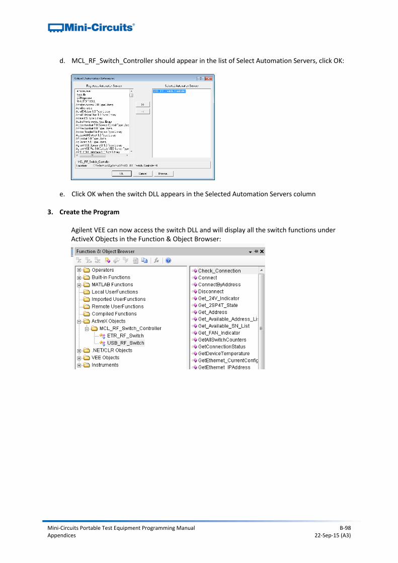
Mini-Circuits Portable Test Equipment Programming Manual B-98 Appendices 22-Sep-15 (A3)
d. MCL_RF_Switch_Controller should appear in the list of Select Automation Servers, click OK:
e. Click OK when the switch DLL appears in the Selected Automation Servers column 3. Create the Program
Agilent VEE can now access the switch DLL and will display all the switch functions under ActiveX Objects in the Function & Object Browser:
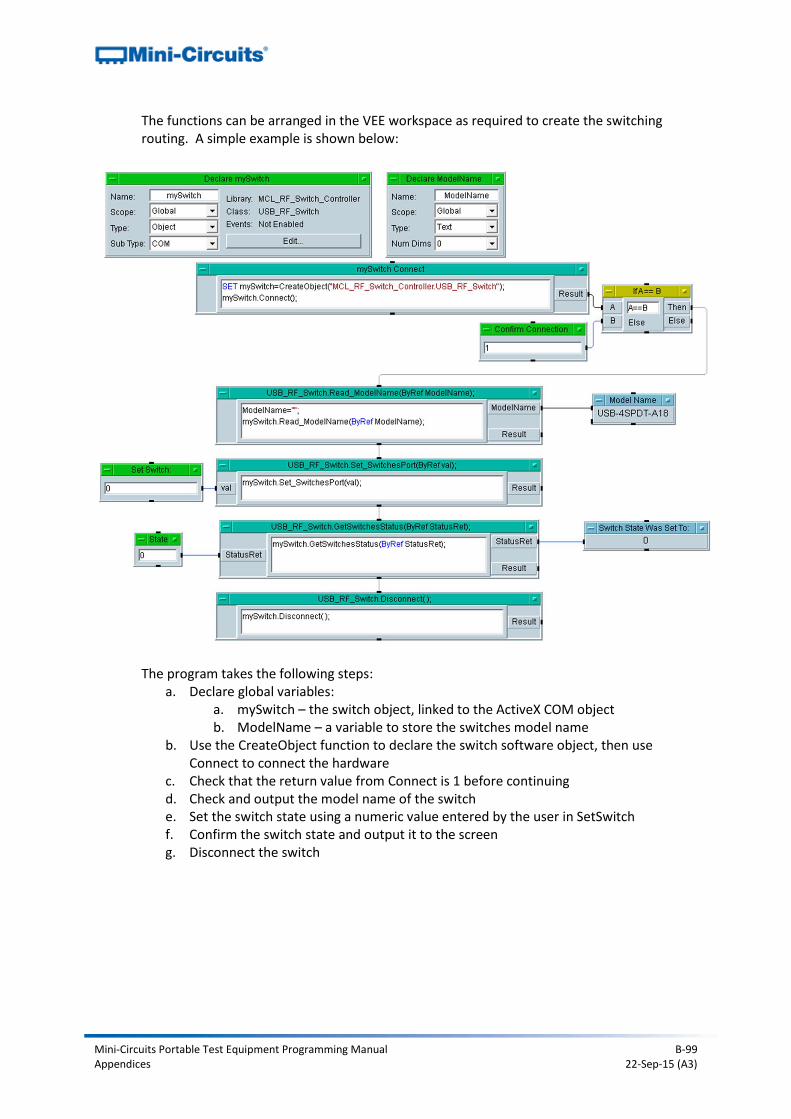
Mini-Circuits Portable Test Equipment Programming Manual B-99 Appendices 22-Sep-15 (A3)
The functions can be arranged in the VEE workspace as required to create the switching routing. A simple example is shown below:
The program takes the following steps: a. Declare global variables:
a. mySwitch – the switch object, linked to the ActiveX COM object b. ModelName – a variable to store the switches model name
b. Use the CreateObject function to declare the switch software object, then use Connect to connect the hardware
c. Check that the return value from Connect is 1 before continuing d. Check and output the model name of the switch e. Set the switch state using a numeric value entered by the user in SetSwitch f. Confirm the switch state and output it to the screen g. Disconnect the switch
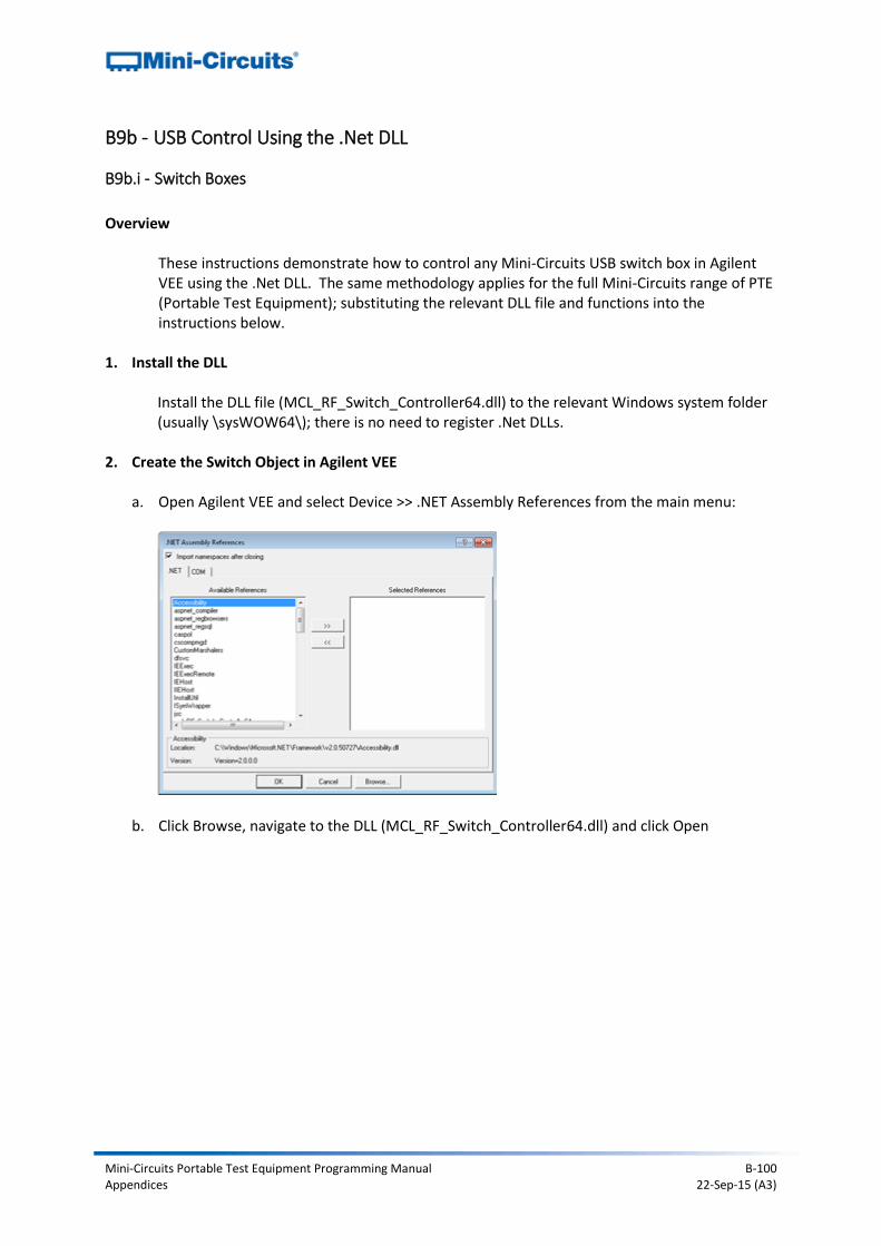
Mini-Circuits Portable Test Equipment Programming Manual B-100 Appendices 22-Sep-15 (A3)
B9b - USB Control Using the .Net DLL
B9b.i - Switch Boxes
Overview
These instructions demonstrate how to control any Mini-Circuits USB switch box in Agilent VEE using the .Net DLL. The same methodology applies for the full Mini-Circuits range of PTE (Portable Test Equipment); substituting the relevant DLL file and functions into the instructions below.
1. Install the DLL Install the DLL file (MCL_RF_Switch_Controller64.dll) to the relevant Windows system folder (usually \sysWOW64\); there is no need to register .Net DLLs.
2. Create the Switch Object in Agilent VEE
a. Open Agilent VEE and select Device >> .NET Assembly References from the main menu:
b. Click Browse, navigate to the DLL (MCL_RF_Switch_Controller64.dll) and click Open
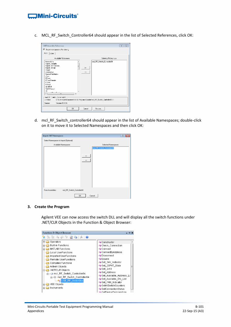
Mini-Circuits Portable Test Equipment Programming Manual B-101 Appendices 22-Sep-15 (A3)
c. MCL_RF_Switch_Controller64 should appear in the list of Selected References, click OK:
d. mcl_RF_Switch_controller64 should appear in the list of Available Namespaces; double-click on it to move it to Selected Namespaces and then click OK:
3. Create the Program
Agilent VEE can now access the switch DLL and will display all the switch functions under .NET/CLR Objects in the Function & Object Browser:
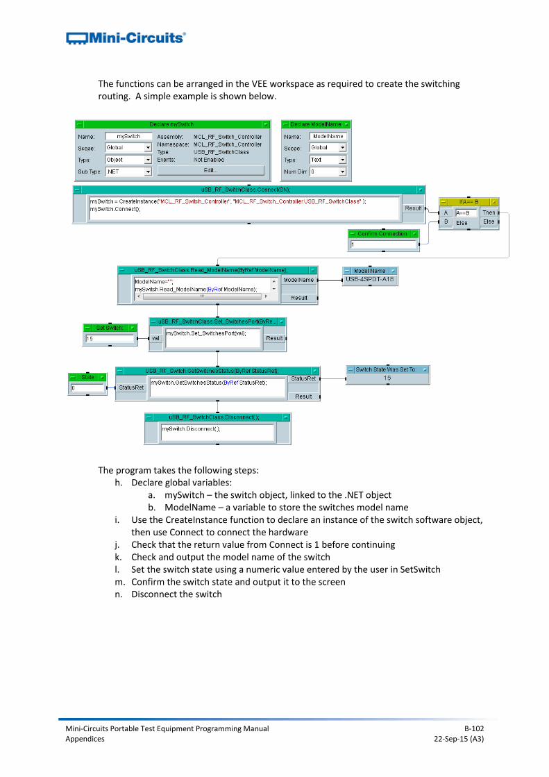
Mini-Circuits Portable Test Equipment Programming Manual B-102 Appendices 22-Sep-15 (A3)
The functions can be arranged in the VEE workspace as required to create the switching routing. A simple example is shown below.
The program takes the following steps: h. Declare global variables:
a. mySwitch – the switch object, linked to the .NET object b. ModelName – a variable to store the switches model name
i. Use the CreateInstance function to declare an instance of the switch software object, then use Connect to connect the hardware
j. Check that the return value from Connect is 1 before continuing k. Check and output the model name of the switch l. Set the switch state using a numeric value entered by the user in SetSwitch m. Confirm the switch state and output it to the screen n. Disconnect the switch
Mini-Circuits Portable Test Equipment Programming Manual C-1 Appendices 22-Sep-15 (A3)
Appendix C - Troubleshooting
C1 - Working with the DLL Files
C1a - File Placement 32-bit Operating Systems The default DLL file location is the System32 sub-folder of the Windows root directory, usually: C:\Windows\System32\
ActiveX DLL files must be placed in this directory
.NET DLL files can generally be placed in any directory as long as the correct reference is set within the programming environment. However, if there is an issue with using the DLL then we would recommend placing it in the default directory as the first step in troubleshooting.
64-bit Operating Systems The default DLL file location is the SysWoW64 sub-folder of the Windows root directory, usually: C:\Windows\SysWOW64\
ActiveX DLL files must be placed in this directory
.NET DLL files can generally be placed in any directory as long as the correct reference is set within the programming environment. However, if there is an issue with using the DLL then we would recommend placing it in the default directory as the first step in troubleshooting.
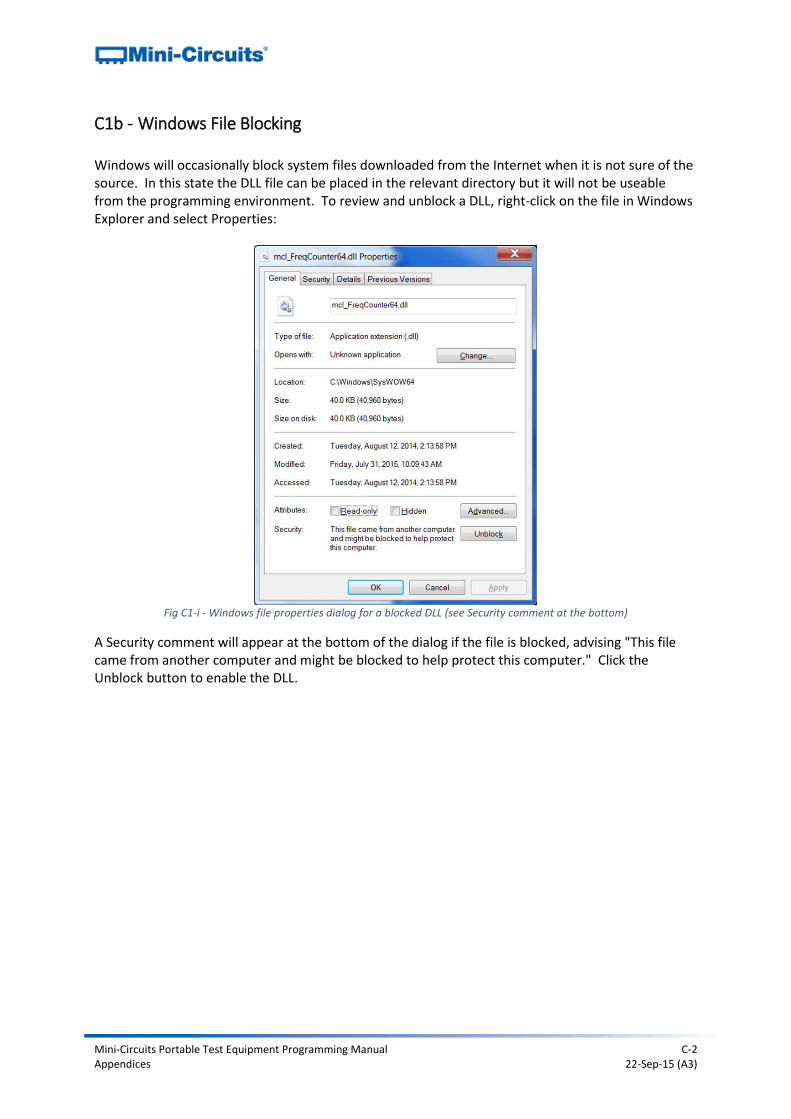
Mini-Circuits Portable Test Equipment Programming Manual C-2 Appendices 22-Sep-15 (A3)
C1b - Windows File Blocking Windows will occasionally block system files downloaded from the Internet when it is not sure of the source. In this state the DLL file can be placed in the relevant directory but it will not be useable from the programming environment. To review and unblock a DLL, right-click on the file in Windows Explorer and select Properties:
Fig C1-i - Windows file properties dialog for a blocked DLL (see Security comment at the bottom)
A Security comment will appear at the bottom of the dialog if the file is blocked, advising "This file came from another computer and might be blocked to help protect this computer." Click the Unblock button to enable the DLL.
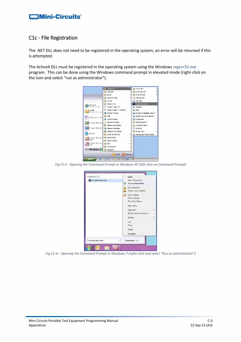
Mini-Circuits Portable Test Equipment Programming Manual C-3 Appendices 22-Sep-15 (A3)
C1c - File Registration The .NET DLL does not need to be registered in the operating system; an error will be returned if this is attempted. The ActiveX DLL must be registered in the operating system using the Windows regsvr32.exe program. This can be done using the Windows command prompt in elevated mode (right-click on the icon and select "run as administrator").
Fig C1-ii - Opening the Command Prompt in WIndows XP (left-click on Command Prompt)
Fig C1-iii - Opening the Command Prompt in Windows 7 (right-click and select "Run as administrator")
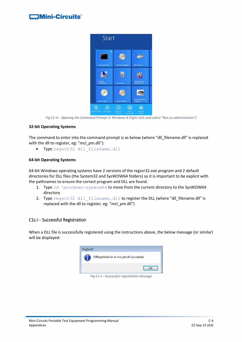
Mini-Circuits Portable Test Equipment Programming Manual C-4 Appendices 22-Sep-15 (A3)
Fig C1-iv - Opening the Command Prompt in Windows 8 (right-click and select "Run as administrator")
32-bit Operating Systems The command to enter into the command prompt is as below (where "dll_filename.dll" is replaced with the dll to register, eg: "mcl_pm.dll"):
Type regsvr32 dll_filename.dll 64-bit Operating Systems 64-bit Windows operating systems have 2 versions of the regsvr32.exe program and 2 default directories for DLL files (the System32 and SysWOW64 folders) so it is important to be explicit with the pathnames to ensure the correct program and DLL are found.
1. Type cd \windows\syswow64 to move from the current directory to the SysWOW64 directory
2. Type regsvr32 dll_filename.dll to register the DLL (where "dll_filename.dll" is replaced with the dll to register, eg: "mcl_pm.dll")
C1c.i - Successful Registration
When a DLL file is successfully registered using the instructions above, the below message (or similar) will be displayed:
Fig C1-v - Successful registration message
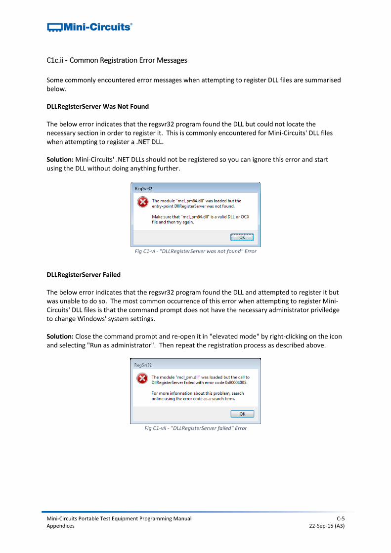
Mini-Circuits Portable Test Equipment Programming Manual C-5 Appendices 22-Sep-15 (A3)
C1c.ii - Common Registration Error Messages
Some commonly encountered error messages when attempting to register DLL files are summarised below. DLLRegisterServer Was Not Found The below error indicates that the regsvr32 program found the DLL but could not locate the necessary section in order to register it. This is commonly encountered for Mini-Circuits' DLL files when attempting to register a .NET DLL. Solution: Mini-Circuits' .NET DLLs should not be registered so you can ignore this error and start using the DLL without doing anything further.
Fig C1-vi - "DLLRegisterServer was not found" Error
DLLRegisterServer Failed The below error indicates that the regsvr32 program found the DLL and attempted to register it but was unable to do so. The most common occurrence of this error when attempting to register Mini-Circuits' DLL files is that the command prompt does not have the necessary administrator priviledge to change Windows' system settings. Solution: Close the command prompt and re-open it in "elevated mode" by right-clicking on the icon and selecting "Run as administrator". Then repeat the registration process as described above.
Fig C1-vii - "DLLRegisterServer failed" Error
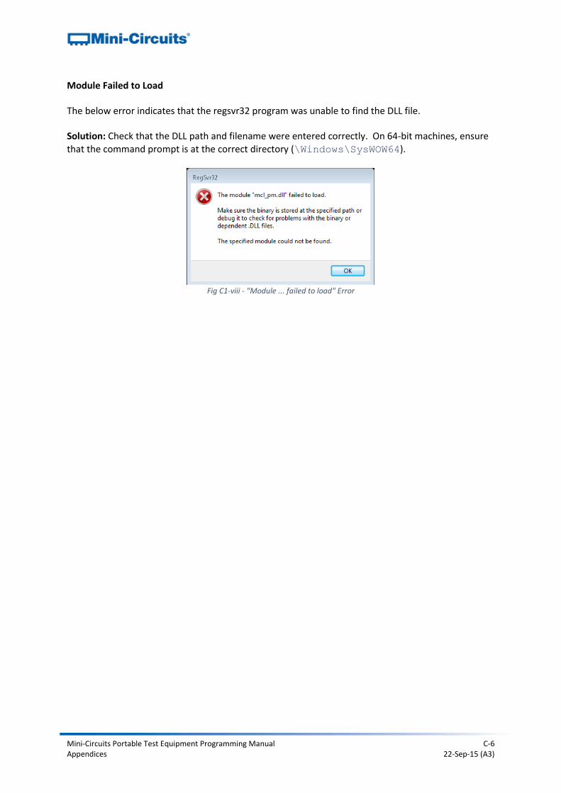
Mini-Circuits Portable Test Equipment Programming Manual C-6 Appendices 22-Sep-15 (A3)
Module Failed to Load The below error indicates that the regsvr32 program was unable to find the DLL file. Solution: Check that the DLL path and filename were entered correctly. On 64-bit machines, ensure that the command prompt is at the correct directory (\Windows\SysWOW64).
Fig C1-viii - "Module ... failed to load" Error