Embed Size (px)
Citation preview

Revision Date: 12/15/04
77
Programmable Attenuators &
Attenuator/Switch Controllers
General InformationIn this section of the catalog, each Programmable Attenuator is outlined utilizing individual data sheets con-taining product features, specifications, and outline drawings. These data sheets are preceded by a quickreference guide to help you select the Programmable Attenuator(s) that fits your needs. The page number for eachProgrammable Attenuator data sheet is given in the quick reference guide.
This section includes all available accessories for the Aeroflex / Weinschel programmable attenuators such as ourModel 8210A Attenuator / Switch Controller, product specific driver boards, and our programmable attenuators withour built-in microprocessor-based drivers. Also Included in this section are Aeroflex / Weinschel's wide variety ofprogrammable attenuator units which includes the 8310, 8311 and 8312 series. Other subsystem solutions can belocated in the Subsystem and Accessories section (pg 129).
NOTE: EXPRESS Shipment available via www.sicklesonline.com or 800-542-4457. Check with distributor for current product stocking quantities.
o Widest Selection of Attenuation Ranges & Steps Sizes
o Express shipment available on select models.
o Built-In TTL\CMOS Interface Driver Circuitryavailable.
o High Quality Construction & Connectorso Special Configurations Available Upon
Request- Custom Cell/Step Size Configurations- Higher Frequencies
6 GHz Designs

Frequency Attenuation Step Insertion Maximum Connector Average PeakModel Range Range Size Loss, Max. SWR Type Power Power PageNumber (GHz) (dB) (dB) (dB) (Watts) (Watts) No.
3200T-1 dc-2.0 0-127 1 4.75 1.25-1.35* SMA 1 50 933200T-2 0-63.75 0.25 4.75 1.25-1.35*3201T-1 0-31 1 3.75 1.253201T-2 0-120 10 3.75 1.253201T-4 0-1.2 0.1 3.30 1.253205T-1 0-70 10 3.30 1.253205T-2 0-55 5 3.30 1.253205T-3 0-1.5 0.1 3.30 1.253206T-1 0-63 1 4.00 1.253209T-1 0-64.5 0.1 6.70 1.353200T-1E dc-3.0 0-127 1 4.90 1.20-1.40* SMA 1 50 933200T-2E 0-63.75 0.25 4.90 1.20-1.40*3201T-1E 0-31 1 3.40 1.20-1.40*3205T-3E 0-1.5 0.1 3.40 1.20-1.40*3206T-1E 0-63 1 3.70 1.25-1.35*3209T-1E 0-64.5 0.1 5.50 1.35-1.45*
3250T-63 dc-1.0 0-63 1 4.75 1.20-1.30* BNC 1 50 96(75 Ω)
3406T-55 dc-6.0 0-55 1 3.80 130 SMA 1 503408T-55.75 0-55.75 0.25 5.003408T-103 0-103 1(New)
* VARIES WITH FREQUENCY.
EXPRESS Shipment available via www.sicklesonline.com or 800-542-4457.Check with Distributor for other available models.
5305 Spectrum Drive, Frederick, MD 21703-7362 TEL: 301-846-9222, 800-638-2048 Fax: 301-846-9116
web: www.aeroflex-weinschel.com email: [email protected]
78
Revision Date: 12/11/05
Programmable Attenuators
Frequency Attenuation Step Insertion Maximum Connector Average PeakModel Range Range Size Loss, Max. SWR Type Power Power PageNumber (GHz) (dB) (dB) (dB) (Watts) (Watts) No.
3200-1 dc-2.0 0-127 1 4.75 1.25-1.35* SMA 1 50 873200-2 0-63.75 0.25 4.75 1.25-1.35*3201-1 0-31 1 3.75 1.253201-2 0-120 10 3.75 1.253205-1 0-70 10 3.30 1.253205-2 0-55 5 3.30 1.253205-3 0-1.5 0.1 3.30 1.253206-1 0-63 1 4.00 1.253209-1 0-64.5 0.1 6.70 1.353200-1E dc-3.0 0-127 1 4.90 1.25-1.40* SMA 1 50 873200-2E 0-63.75 0.25 4.90 1.25-1.40*3201-1E 0-31 1 3.40 1.25-1.40*3205-3E 0-1.5 0.1 3.40 1.25-1.40*3206-1E 0-63 1 3.70 1.25-1.35*3209-1E 0-64.5 0.1 5.50 1.35-1.45*
3250-63 dc-1.0 0-63 1 4.75 1.20-1.30* BNC 1 50 96(75 Ω)
3406-55 dc-6.0 0-55 1 3.80 130 SMA 1 50 1003408-55.75 0-55.75 0.25 5.003408-103 0-103 1(New)
Relay Switched Programmable Attenuators, Basic Models . . . DC-6 GHz
Relay Switched Programmable Attenuators, with built-in Microprocessor-Base Driver . . .
DC-3 GHz (For use with Aeroflex / Weinschel 8210A Controller)
795305 Spectrum Drive, Frederick, MD 21703-7362 TEL: 301-846-9222, 800-638-2048 Fax: 301-846-9116
web: www.aeroflex-weinschel.com email: [email protected] Date: 12/15/04
Programmable Attenuators
Frequency Attenuation Step Insertion Maximum Connector Average PeakModel Range Range Size Loss, Max. SWR Type Power Power PageNumber (GHz) (dB) (dB) (dB) (Watts) (Watts) No.
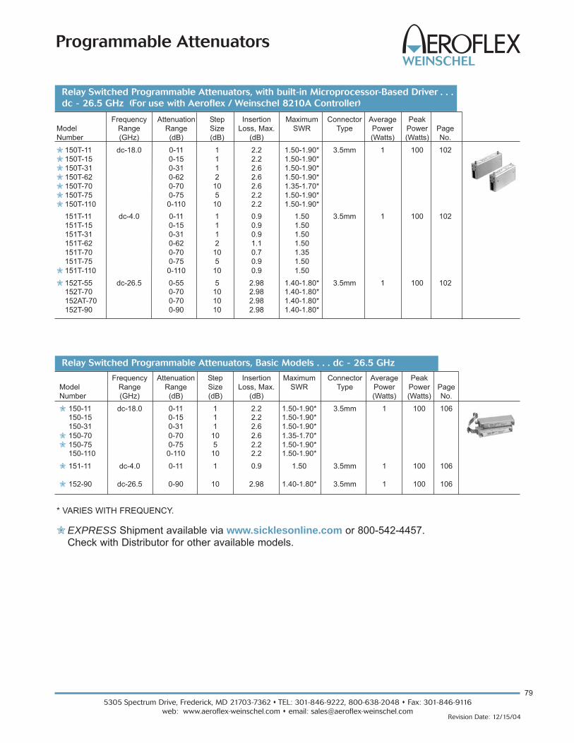
150T-11 dc-18.0 0-11 1 2.2 1.50-1.90* 3.5mm 1 100 102150T-15 0-15 1 2.2 1.50-1.90*150T-31 0-31 1 2.6 1.50-1.90*150T-62 0-62 2 2.6 1.50-1.90*150T-70 0-70 10 2.6 1.35-1.70*150T-75 0-75 5 2.2 1.50-1.90*150T-110 0-110 10 2.2 1.50-1.90*151T-11 dc-4.0 0-11 1 0.9 1.50 3.5mm 1 100 102151T-15 0-15 1 0.9 1.50151T-31 0-31 1 0.9 1.50151T-62 0-62 2 1.1 1.50151T-70 0-70 10 0.7 1.35151T-75 0-75 5 0.9 1.50151T-110 0-110 10 0.9 1.50152T-55 dc-26.5 0-55 5 2.98 1.40-1.80* 3.5mm 1 100 102152T-70 0-70 10 2.98 1.40-1.80*152AT-70 0-70 10 2.98 1.40-1.80*152T-90 0-90 10 2.98 1.40-1.80*
Relay Switched Programmable Attenuators, Basic Models . . . dc - 26.5 GHz
Frequency Attenuation Step Insertion Maximum Connector Average PeakModel Range Range Size Loss, Max. SWR Type Power Power PageNumber (GHz) (dB) (dB) (dB) (Watts) (Watts) No.
150-11 dc-18.0 0-11 1 2.2 1.50-1.90* 3.5mm 1 100 106150-15 0-15 1 2.2 1.50-1.90*150-31 0-31 1 2.6 1.50-1.90*150-70 0-70 10 2.6 1.35-1.70*150-75 0-75 5 2.2 1.50-1.90*150-110 0-110 10 2.2 1.50-1.90*
151-11 dc-4.0 0-11 1 0.9 1.50 3.5mm 1 100 106
152-90 dc-26.5 0-90 10 2.98 1.40-1.80* 3.5mm 1 100 106
* VARIES WITH FREQUENCY.
EXPRESS Shipment available via www.sicklesonline.com or 800-542-4457.Check with Distributor for other available models.
Relay Switched Programmable Attenuators, with built-in Microprocessor-Based Driver . . .
dc - 26.5 GHz (For use with Aeroflex / Weinschel 8210A Controller)

5305 Spectrum Drive, Frederick, MD 21703-7362 TEL: 301-846-9222, 800-638-2048 Fax: 301-846-9116
web: www.aeroflex-weinschel.com email: [email protected]
80
Revision Date: 12/15/04
Programmable Attenuators
Frequency Attenuation Step Insertion Maximum AverageModel Range Range Size Loss, Max. SWR Power Connector PageNumber (GHz) (dB) (dB) (dB) Type No.
4216-63 0.8-2.3 0-63 1 3.40 150 +28 dBm SMA 1114218-63.75 0-63.75 0.25 4.90 1504218-127 0-127 1 4.90 150
4226-63 0.8-3.0 0-63 1 3.75 1.50 +28 dBm SMA 1134228-63.75 0.8-2.5 0-63.75 0.25 4.50 1.504228-103 0.8-3.0 0-103 1 5.50 1.50(New)
4238-63.75 0-63.75 0.25 9.00 1.60 +30 dBm SMA 1154238-103 103 1 9.00(New)
4246-63 10 MHz-2.5 0-63 1 10.00 2.00 +36 dBm SMA 1174248-63.75 0-63.75 0.25 13.004248-103 103/1 13.00(New)
EXPRESS Shipment available via www.sicklesonline.com or 800-542-4457.Check with Distributor for other available models.
SOLID-STATE PROGRAMMABLES . . . to 3 GHz

815305 Spectrum Drive, Frederick, MD 21703-7362 TEL: 301-846-9222, 800-638-2048 Fax: 301-846-9116
web: www.aeroflex-weinschel.com email: [email protected] Date: 12/15/04
Programmable Attenuators
Programmable Attenuator Units for Rack
or Bench Use:
(Pages 119-122)
Aeroflex / Weinschel's 8310 &8311 Series ProgrammableAttenuator Units representAeroflex / Weinschel's newestconcept in programmableattenuation for bench test andsubsystem applications.
Standard 8310 Series designs house and control variousAeroflex / Weinschel Programmable Attenuator Models(3200T, 150T, and 4200 Series via front panel controls orstandard communications interfaces including GPIB (IEEE-488) and RS-232/RS-422/RS485. The standard unitscombine the features of the Aeroflex / Weinschel 8210ADevice Controller with a front panel user interface to form aflexible, easy to use solution.
Most 8310 Series are single channel configurations whereRF signal is routed through either the front or rear mountedPorts A & B but can be configured for up to four channels ofattenuation, RF switching, or other functions and other fea-tures such as:
o Multi-Channel attenuation paths (up to 4 input/outputs).
o Relative vs. Nominal attenuation step function.
o Wide choice of Frequency & Attenuation Ranges.- dc to 1, 2, 3, 18 & 26.5 GHz- up to 127 dB- Solid-State (GaAs FET & PIN)- Relay Switched- 50 & 75 Ω Configurations
o High Accuracy & Repeatability.
o Easily mounted into racks or cabinets designed perEIA RS-310 or MIL-STD-189.
Programmable/Switch Controllers:
(pg 126-128)
The Model 8210A Attenuator / Switch Controller provides aflexible, low cost solution for the control and operation ofelectromechanical switches and programmable step attenu-ators using standard communication interfaces. The 8210Arepresents a new concept in device control applications forbench test and subsystem designs.
o Designed to interface with Aeroflex / Weinschel’s line of programmable attenuators (3200T & 150T) and other electromechanical devices.
o Simplifies your bench test setupsand subsystem design.
o Available in two standard communication interfaces:
- Model 8210A-1:GPIB/IEEE-488 (HS-488 ready)- Model 8210A-2:RS-232, RS-422, RS-485
Each model contains similar capabilities and providesswitch-selectable parameters to tailor the interface’s operation.
100 W Hot-Switchable High Power
Attenuator Unit:
(pages 123-125) o Available in 0-15 dB or
0-31 dB Configurations o DC to 13 GHz
Operationo Power Handling up to 100 Watts averageo High Accuracy & repeatabilityo IEEE-488 & Standard Serial Interfaces
o Relative vs. Nominal attenuation step function.o Bus Controlled Programmable Attenuator Units
ATTENUATOR UNITS & CONTROLLERS. . . dc to 26.5 GHz, 100 Watts

5305 Spectrum Drive, Frederick, MD 21703-7362 TEL: 301-846-9222, 800-638-2048 Fax: 301-846-9116
web: www.aeroflex-weinschel.com email: [email protected]
82
Revision Date: 12/20/05
Programmable Attenuators
What are the applications of Aeroflex / Weinschel
programmable attenuators?
Aeroflex / Weinschel's programmable attenuators are usedto control the power of radio frequency and microwave sig-nals. Applications include control of input power to signalmeasuring systems, control of output power from signalgenerating systems, adjustment power for BIT error ratetesting, controlling losses in a signal path and simulating thesignal fading of a microwave communication system....toname just a few.
How do they work?
Aeroflex / Weinschel's programmable attenuators consist ofa series of attenuation pads (cells) that are selectivelyinserted into the signal path via a control signal. An exam-ple is a series of cells such as 1, 2, 4, 8 and 16 dB arrangedin a binary sequence. Such an attenuator is called a binaryattenuator. Combinations of cells are switched "on" to pro-vide attenuation steps from 0 dB to 31 dB. Another exampleis a unit having cell values of 10, 20 and 40 dB which willprovide 10 dB steps between 0 dB and 70 dB.
How are the attenuators switched?
The basic structure of a programmable attenuator is shownbelow. There are several ways the attenuator pads areswitched in and out of the RF path. Aeroflex / Weinschel's3200 series uses TO-5 can relay switches. These are use-ful up to 2.0 GHz and higher. Aeroflex / Weinschel's 150series operate up to 26.5 GHz and utilize reed switcheshoused within a precision machined cavity.
Aeroflex / Weinschel also manufactures programmableattenuators using solid state switching that offers fasterswitching speeds but their frequency range is more limitedthan mechanical step attenuators. Whereas mechanicallyswitched attenuators operate from DC to their maximum fre-quency, solid state attenuators have a lower frequency limit.Solid state attenuators also have lower isolation betweencontrol and through path.
Frequently Asked Questions about Programmable Attenuators....
How fast do the attenuators switch?
Switching speed of mechanically switched attenuators istypically between 6 and 35 msec. This is the maximum timebetween the application of the switching command to thecell and the cessation of contact bounce. This time is a func-tion of switch structure and size.
What is a latching and
non-latching attenuator?
Non-latching is also calledmomentary or fail-safe. Forthe non-latching type, theattenuator is switched to theattenuation "on" position onlyso long as control power is appliedto the switch. As soon as power isremoved the switch reverts to it passivestate or fail-safe state...usually the zero dB state. In latchingattenuators each cell stays in the last setting even if poweris removed. Latching attenuators have two control lines.One control line causes the attenuator to switch to the"attenuation on" setting while the other control line causesthe attenuator to switch to the zero dB setting. There is nor-mally a permanent magnet that holds the switch stable ineither position. Each version has its advantages and disadvantages. Thenon-latching switch requires constant power to the solenoidwhen in the "on" position. On the other hand the latchingversion requires greater switch current to overcome it's per-manent magnet.
How are the attenuators controlled?
The Model 3200 & 3400 Series non-latching attenuatorsrequire only one 12 volt control line per cell. The direction ofcontrol current is not important.The Model 150 Series is a latching version using one posi-tive 5 volt or 24 volt common return line and two groundingcontrol lines. In order for switching to be guaranteed the voltage betweencommon and control must be held within specified limits.Power supply regulation must be kept within range evenwhile heavy switching current is being drawn. Any cablevoltage drops must be added to the minimum control volt-age to obtain the required power supply voltage at theattenuator. Aeroflex / Weinschel's programmable attenuators, such asthe Model 3200T, 3400T and 150T Series feature on-boardTTL drivers. TTL driver boards are also available for theModel 150 Series attenuators.

835305 Spectrum Drive, Frederick, MD 21703-7362 TEL: 301-846-9222, 800-638-2048 Fax: 301-846-9116
web: www.aeroflex-weinschel.com email: [email protected] Date: 12/15/04
Programmable Attenuators
What is the switch life of these programmable
attenuators?
Specified life for mechanical switches is normally in therange of 1 to 10 million switching. This specification is perswitch, independent of the other switches in the attenuator.For the Model 150 series attenuators the specification is 5million cycles, i.e. one cycle is the switch moving in bothdirections. These specifications are based on the mechani-cal life of the switch, however, other factors have an impacton attenuator life. High power operation can have anadverse effect on the switch contact surfaces. This canreduce the overall life of the switch by causing the attenua-tor performance to go outside it's specification.
What is monotonicity?
A programmable step attenuator is considered monotonic ifit's attenuation always increases when it is commanded toincrease. This applies on a per frequency basis. Forinstance the 20 dB setting at 1 GHz will always be less thanthe 21 dB setting at 1 GHz. This does not necessarily meanthat the 20 dB setting at 1 GHz will always be less than the21 dB setting 18 GHz. Monotonicity is influenced by theSWR of the individual attenuator cells as the cells are com-bined to form an attenuation value. It is also influenced bythe summation of individual cell attenuation tolerances asthe cells are combined.
What is the difference between insertion loss and
incremental attenuation?
Programmable attenuators have insertion loss and alsoincremental attenuation. Insertion loss is the loss throughthe attenuator when all cells are switched to zero dB. It isthe residual loss of the device itself. Insertion loss usuallyincreases with frequency reaching several dB at the higherfrequencies and generally has very flat frequency response.Incremental attenuation is the attenuation values of theattenuators cells relative to the insertion loss. Since inser-tion loss is always present, the performance of aprogrammable attenuator is always given as incrementalattenuation relative to insertion loss. Insertion loss is con-sidered part of the fixed performance of the system path inwhich the programmable attenuator is located.
What is the advantages of Attenuators with built-in
driver circuitry?
These attenuators feature an internal microcontroller-baseddriver that provides a TTL-level digital interface for controlof the attenuator relays (Figure 1). This card simplifiesoperation and interfacing requirements, while at the sametime providing for greatly enhanced flexibility over pastdesigns. User-selectable modes of operation include bothparallel and serial bus. The parallel mode provides a sim-ple, one-bit per relay on/off control with internal pullups foruse primarily in single attenuator applications. This modeallows the attenuator to be controlled via a variety ofmethods, such as a TTL-level digital output port, ormechanical toggle switches. The serial mode provides atwo-wire serial bus structure and protocol for connecting a
number of devices to a single host control interface, suitablefor use in larger system and sub-system applications. Thebuilt-in driver™ contains non-volatile configuration memorythat is used to hold a wide variety of attenuator and driver-dependent parameters, including serial number, attenuatorcell dB values, relay configurations, and switching require-ments, which are all accessible via the digital interface. Thisfrees the system designer from such low-level details, allow-ing faster integration. In either operational mode, themicrocontroller enters an idle condition during periods ofinactivity, turning off all on-board clocks, reducing EMI con-cerns, and lowering power consumption. On-boardregulation for the digital circuitry allows the programmableattenuator to operate from a single input supply voltage.
Figure 1. Digital Driver Circuitry
Non-VolatileConfiguration
Memory
Single-ChipMicrocontroller
RelayDrivers
TTL/CMOSCompatibleDigital Interface
+12 to+15 VInput
ToAttenuator
Relays
EMIFilters
+5 VRegulator
How can I control the Attenuators with built-in drivers?
The communications interface (Model 8210A) provides aflexible, low cost solution for the operation of programma-ble step attenuators and other electromechanical devicesunder computer control. Designed to interface to Aeroflex /Weinschel’s line of programmable attenuators built-in intel-ligent drivers, the Model 8210A represents a new concept indevice control applications for bench test and subsystemdesigns. The 8210A communications interface provides ahigh-level interface from various industry standard commu-nications interfaces, including IEEE-488 and RS232/RS422/RS485, to the programmable attenuators serialDriver Interface Bus.

5305 Spectrum Drive, Frederick, MD 21703-7362 TEL: 301-846-9222, 800-638-2048 Fax: 301-846-9116
web: www.aeroflex-weinschel.com email: [email protected]
84
Revision Date: 12/15/04
Programmable Attenuators
Weinschel has been a major supplier of programmable attenuators to the RF industry for over25 years. Historically the most demanding specifica-
tions for these components have been low insertion loss and SWR,combined with a reasonable life expectancy of several millionswitching cycles. This was usually adequate for RF instrumentslike spectrum analyzers and signal generators, wherein the attenuator bandwidth rather than the switching speed was of primeconcern. To achieve wide bandwidths the programmable attenua-tors were mostly of electromechanical design and the linearity ofthese passive components was not only assumed but never questioned by any customer. Intermodulation distortion discus-sions and problems were usually limited to components such asamplifiers, mixers and filters.
In recent years, however, wireless communication systemsemploying complex digital modulation schemes, increased chan-nel capacity, high transmit power and extremely low receiversensitivity have put into question the linearity of passive compo-nents. Even very low level multi-tone intermodulation productsgenerated by attenuators can seriously degrade the efficiency ofa system/ instrument if these products fall within the user pass-band. For two closely spaced tones at frequencies f1 and f2, thethird order IM products at 2f1 - f2 and 2f2 - f1 , are the mostharmful distortion products. They are harmful because they arelocated close to f1 and f2 and virtually impossible to filter out. Intoday's base stations the multicarrier power amplifier (MCPA) isreplacing banks of single-channel amplifiers and their corre-sponding power combining network. MCPAs have the capabilityof carrying a number of modulation schemes simultaneously andcan also employ schemes such as dynamic-channel-allocation(DCA) to use the allocated frequency spectrum more efficiently.The in-band intermodulation distortion (IMD) performance ofthese amplifiers is extremely critical and needs to be measuredusing low distortion programmable multi-tone generators whoseIMD performance must be quite superior. This is discussed in thetwo case studies cited here.
Electromechanical programmable attenuators obviouslyprovide a far superior IMD performance than
their corresponding solid state counterparts employing semi-conductor switching elements.
However, their slow switch speed, in the order of millisec-onds, and short switch life in the order of 5-10 million cyclesmake them unattractive in some applications like cell phone test-ing and other ATE systems. Solid State programmable attenuatorsdo overcome these two problems and are therefore included herefor IMD performance comparison. It is not the intent of this briefarticle to go into the theory of intermodulation distortion. The goalhere is to provide some good basic IMD test data for a variety of commercial programmable attenuators and let the enduser select the most appropriate type for his application.
Measurement System and Parameters...All test data presented here was generated using a
commercially available Passive IM Analyzer, Summitek ModelSI-800A which provides a fully integrated system for characteriz-ing distortion produced by cables, attenuators and other passivedevices. Although the system is capable of measuring both,through and reflected IM3, IM5, IM7 and IM9, the focus here isonly on through IM for the most troublesome third order product,IM3. To carry out a meaningful comparison between differentattenuators all measurements were carried out using two equalamplitude input tones at 869 MHz (f1) and 891 MHz(f2) , the IM3frequency being 847 MHz (2f1-f2). Input carrier power wasstepped in increments of 1 dB from -7dBm to +27dBm. All exter-nal adapters and cables were carefully selected to maintain thesystem's residual IM level of around -120 dBm. Although the sys-tem permitted receiver measurements between -70 to -120 dBmwe restricted all measurements between -85 to -110 dBm byusing a calibrated low IM coupler and attenuators at the outputport of the DUT. One must be aware that the accuracy of suchsmall signal measurements can easily be off by 2 to 3 dB sorestricting the measurement dynamic range helps reduce thereceiver non-linearity error. Measurements were done over sev-eral days to ensure stability and repeatability.
Distortion Comparison for Basic Types of
Programmable Attenuators...The programmable attenuators discussed here are the
switched type with a discrete number of `cells'. Switchingbetween the zero and attenuate state on each cell is achieved bya DPDT switch configuration. The cell values are usually in abinary sequence. For example a 6 cell/6 bit unit could have 1, 2,4, 8, 16 and 32 dB sections providing a 63 dB dynamic range in1dB increments. Four basic families of programmable attenua-tors are compared, each family being identified by the switchelement used to achieve the transfer from zero to attenuate state.
For the purposes of distortion comparison it was deemed necessary to select units with similar electrical length and/or programmability. Both the electromechanical units, TO5 relayand edge-line type, had an electrical length of about 20 cms. Thetwo solid state units had 6 cell programmability yielding 63 dB in1 dB step size. All IM3 vs Pin measurements were done with theattenuators programmed to be in their characteristic zero insertionloss state. The zero state was selected because it generated the highest IM3 levels. The graph below shows the
Intermodulation Distortion in Programmable Attenuators....

855305 Spectrum Drive, Frederick, MD 21703-7362 TEL: 301-846-9222, 800-638-2048 Fax: 301-846-9116
web: www.aeroflex-weinschel.com email: [email protected] Date: 12/15/04
Programmable Attenuators
obvious compromise in IMD performance for the two solid statetypes. It is worth noting that the IM3 vs Pin slope is not exactly3:1 as would be the case in a perfect third order device. The the-oretical two tone third order intercept point, IP3, commonly usedas a figure of merit for comparing linearity is shown in the fol-lowing table at two different input power levels. The input IP3 isderived from the following relation:
Input IP3 = 3(Pin-α)-IM3 + α2
where α = zero insertion loss of each unit @ 847 MHz, the IM3 fre-quency. IM3 and Pin are selected from Table 1.
IM3 Performance of Electromechanical & Solid StateProgrammable Attenuators
-150
-140
-130
-120
-110
-100
-90
-80
-70
-60
-50
-40
-30
-20
-10
0
-7 -6 -5 -4 -3 -2 -1 0 1 2 3 4 5 6 7 8 9 10 1 1 12 1 3 1 4 15 1 6 1 7 18 1 9 2 0 2 1 22 2 3 2 4 25 2 6 2 7
Input Power, Pin (dBm) each tone
Thr
ough
IM3
(dB
m) PIN switched - 4216 series
FET switched - 4206 series
TO5 relay switched - 3200 series
Edge-line reed switched 150 series
Weinschel Series 4206, 4216, 3200 & 150Low Carrier Frequency: 869.0 MHzHigh Carrier Frequency: 891.0 MHzIM3 Frequency: 847.0 MHz
Passive IM3 Measurement
Attenuator TypeParameter PIN FET Relay Edge-LineIP3 @ 42.0 dBm 48.0 dBm 72 dBm 98 dBm*10 dBmIP3 @ 39.0 dBm 53.5 dBm 75 dBm 98 dBm24dBmI. Loss 2.0 dB 5.0 dB 1.5 dB 0 dB Switching 2 µsec 2 µsec 5 msec 20 msecTime
Switch Life ∞ ∞ 10 million 5 millionFrequency 0.8-2.3 0.01-2.5 dc-3 dc-26.5(GHz)* NOTE: Although the actual IM3 was not measurable the curve for the edge-lineunit is linear and predictable unlike the two curves for the solid state attenuators. Ifwe were to extrapolate this curve we would get the same IP3 figure of +98dBm asexpected.
TABLE 1. SPECIFICATION COMPARISONS:

5305 Spectrum Drive, Frederick, MD 21703-7362 TEL: 301-846-9222, 800-638-2048 Fax: 301-846-9116
web: www.aeroflex-weinschel.com email: [email protected]
86
Revision Date: 12/15/04
Programmable Attenuators
Case Study 1Company A offers its IMD series Phase Aligned 8 tone gen-
erators to test intermodulation distortion in multi-carrier poweramplifiers. The output level of these generators is accurately con-trolled using a Weinschel TO5 relay based programmableattenuator offering over 60 dB dynamic range. Eight +13 dBmcarriers are input to the attenuator. In MCPAs with feedforwardcorrection, in-band IMD levels could be as low as -75 dBc soCompany A wanted at least -85 dBc at the output of their gener-ator. The first problem was that Weinschel could not simulate theexact test conditions. This was readily resolved by establishing agood co-relation between our two tone IM3 measurement andCompany A's 8 tone test. Having employed the best plating tech-niques and using good low IM connector design the attenuatorwas still short of the required IMD spec. The final improvementwas achieved by extensive testing on relays from three differentmanufacturers. Figure 2 shows IM3 plots of the two best per-formers. Manufacturer B consistently provided a 4 to 5 dBimprovement at the two tone level at Pin of +22 dBm and higher.This corresponded to an acceptable output distortion level for theCompany A generator.
Case Study 2
Company B manufactures ultra low distortion multi-tone sig-nal generators. Their units offer up to 160 channels from 5 MHzthrough 1 GHz. Each carrier can be leveled as high as +10 dBm.One of their most stringent requirements is a cross modulationtest. The Company B generator specification is -100 dB below thesideband of a 100% amplitude modulated carrier, which is -110dBc. The actual components used in the critical path had tomeasure -120 dBc or better. Their generator needed an ultra lin-ear attenuator to provide a programmed output level in 0.5 dBincrements. Relay based units were tested and found to be unac-ceptable. The high performance edge-line attenuators wereexpected to solve the problem but at first they too fell short, butmainly in their zero attenuation state, which generates maximumdistortion. Prior to supplying these units to Company B no cus-tomer had asked for a distortion specification on these supposedlypassive attenuators. Environmental performance had warrantedthe use of nickel underplate on the edge lines. This was disclosed
to the customer and suspected to be the prime cause of high IMDlevels. Since the unit was going to be mounted in a benign envi-ronment, elimination of the nickel underplate was not thought tobe a problem. Figure 3 demonstrates the tremendous reduction inIM3 levels upon elimination of the nickel underplate-a significant40 dB! A further 10-15 dB improvement was achieved byredesigning the connectors to reduce their passive IMD. The IMimprovement in these connectors would have served no purposeprior to the elimination of nickel. This is because the main sourceof distortion lay behind the connector back plane, along the edgetransmission line, which had a far greater electrical length thanthe two connectors.
ConclusionAbundant intermodulation test data for four families of pro-
grammable attenuators has been presented in an easy format,together with their other key performance features. This shouldenable instrument and system designers to select the most suitabletype for their application.
The two case studies have also demonstrated that an OEMcomponent supplier cannot possibly simulate the different dis-tortion test scenarios of every customer. Such tests would beextremely varied, complex and cost prohibitive. The IM analyzerused at Weinschel was indeed a narrow band instrument and onemight be concerned about the unit's performance at other fre-quencies. This is a legitimate concern for the solid state types, inwhich the distortion mechanism is a strong function of the operat-ing frequency. For the broadband electromechanical types this isnot a major issue. However, with a meaningful two tone inter-modulation measurement it is quite possible to get an excellentcorrelation with the customer's test conditions and thereby comeup with a corresponding specification under the two tone test. Itis helpful though, to be able to replicate the total power level thatthe unit would be subjected to in the field.
Author: Jimmy Dholoo, VP Engineering @ Aeroflex / Weinschel© April 1999, Wireless Design & Development
Input Power vs.Through IM3 LevelCase Study 1
-115
-105
-95
-85
-75
-65
10 11 12 13 14 15 16 17 18 19 20 21 22 23 24 25 26 27
Input Power, Pin (dBm) each tone
IM3
(dB
m)
Manufacturer A
Manufacturer B
Weinschel 3200-1 with TO5 relays from two different manufacturersLow Carrier Frequency: 869.0 MHzHigh Carrier Frequency: 891.0 MHzIM3 Frequency: 847.0 MHz
Passive IM3 Measurement
Input Power vs. Through IM3 LevelCase Study 2
-140
-130
-120
-110
-100
-90
-80
-70
-60
-7 -6 -5 -4 -3 -2 -1 0 1 2 3 4 5 6 7 8 9 10 11 12 13 14 15 16 17 18 19 20 21 22 23 24 25 26 27
InputPower, Pin(dBm)each Tone
IM3
(dB
m)
Gold plated edge-line with Ni underplate
Gold plated edge-line without Ni underplate
Final design with low IM connectors
Weinschel 150 Series High Frequency Edge-Line Programmable AttenuatorLow Carrier Frequency: 869.0 MHzHigh Carrier Frequency: 891.0 MHzIM3 Frequency: 847.0 MHz
Passive IM3 Measurement

875305 Spectrum Drive, Frederick, MD 21703-7362 TEL: 301-846-9222, 800-638-2048 Fax: 301-846-9116
web: www.aeroflex-weinschel.com email: [email protected] Date: 12/15/04
Programmable Attenuators
Model NO. Attenuation CellNumber Cells Range/Steps Increments
(dB) (dB)
3200-1 8 127/1 1, 2, 4, 8, 16, 32, 64*3200-1E
3200-2 8 63.75/0.25 0.25, 0.5, 1, 2, 4, 8,3200-2E 16, 32
3201-1 5 31/1 1, 2, 4, 8, 163201-1E
3201-2 5 120/10 10, 20, 30, 60**
3205-1 4 70/10 10, 20, 20, 20
3205-2 4 55/5 5, 10, 20, 20
3205-3 4 1.5/0.1 0.1, 0.2, 0.4, 0.83205-3E
3206-1 6 63/1 1, 2, 4, 8, 16, 323206-1E
3209-1 10 64.5/0.1 0.1, 0.2, 0.4, 0.8, 1,3209-1E 2, 4, 8, 16, 32*64 dB cell comprised of two 32 dB cells*60 dB cell comprised of two 30 dB cells
CELL CONFIGURATIONS:
DescriptionThe 3200 Series Programmable Step Attenuators aredesigned for use in automatic test equipment and OEMsystems operating in the dc to 3 GHz frequency range. Thisseries is available in many standard attenuation ranges andcell configurations. Custom designed configurations areavailable upon request. Each cell contains a double-pole,double-throw relay that provides a zero path or attenu-ated path for the RF signal.Microstrip circuitry and special compensation techniquesproduce flat attenuation versus frequency characteristics.The microstrip construction, using thick-film circuit ele-ments, ensures product uniformity. To minimize RFleakage, the 3200 Series Attenuators are provided withgold-plated contact areas and feedthrough filters at eachcontrol terminal.
Model 3200 Series dc to 2.0 GHz
Model 3200 (E Series) dc t0 3.0 GHz
Programmable Attenuators 1 Wattwith optional TTL Interface
Features
o Widest Selection of Attenuation Ranges & StepSizes
o Available Express Models: 3200-1, 3200-1E-23200-2, 3200-2E-23201-1, 3201-23206-1
Other models may be available for Express delivery.o High Quality Construction & Connectorso Special Configurations Available Upon Request
- Custom Cell/Step Size Configurations- 3.0 GHz and Higher Frequencies
SpecificationsNOMINAL IMPEDANCE: 50 ΩFREQUENCY RANGE:dc to 2.0 GHz: 3200-1, 3200-2, 3201-1, 3201-2, 3205-1,
3205-2, 3205-3, 3206-1, 3209-1dc to 3.0 GHz: 3200-1E, 3200-2E, 3201-1E, 3205-3E,
3206-1E, 3209-1E
MAXIMUM SWR:Freq 3200-1 3200-1E 3201-X 3206-1E 3209-1 3209-1ERange 3200-2 3200-2E 3205-X(GHz) 3201-1E 3206-X
3205-3E
dc - 0.2 1.30 1.25 1.30 1.25 1.35 1.350.2 - 1 1.25 1.25 1.25 1.25 1.35 1.351 - 2 1.35 1.25 1.35 1.25 1.35 1.352 - 3 - - - 1.40 - - - 1.35 - - - 1.45
INCREMENTAL ATTENUATION ACCURACY:Frequency AccuracyRange (GHz)
dc - 0.5 + 0.2 dB or 0.5%0.5 - 1 + 0.2 dB or 1.0%1 -3 + 0.3 dB or 2.0%
MONOTONICITY: dc to 3.0 GHzINCREMENTAL TEMPERATURE COEFFICIENT:
30 and 32 dB Cells: 0.00005 dB/dB/°CAll other cells: 0.00002 dB/dB/°C
POWER RATING: 1 watt average to 25°C ambient temperature, derated linearly to 0.25 watt @ 71°C. 50 wattspeak (5 µsec pulse width; 1% duty cycle)
www.sicklesonline.com
E PX R E SS
800-542-4457

5305 Spectrum Drive, Frederick, MD 21703-7362 TEL: 301-846-9222, 800-638-2048 Fax: 301-846-9116
web: www.aeroflex-weinschel.com email: [email protected] Date: 12/15/04
Programmable Attenuators
MODEL NUMBER DESCRIPTION:Example, DC-2 GHz models: 320X-Y For a basic 2 GHz model*320X-Y-1 Add -1 for TTL driver board with a 10 pin
ribbon cable connector.320X-Y-2 Add -2 for TTL driver board with a 15 pin D
type connector.Example, DC-3 GHz models:Add E as in:320X-YE For a basic 3 GHz model*320X-YE-1 Add -1 for a TTL driver board with a 10 pin
ribbon cable connector320X-YE-2 Add -2 for a TTL driver board with a 15 pin
D connector * Use the Cell Configuration table to determine X and Y
for available attenuation ranges. 88
Specifications - Con’t
POWER COEFFICIENT: <0.005 dB/dB/wattRATED SWITCH LIFE: 5 million cycles operations per cell@ 0 dBmSWITCHING TIME: 6 msec. maximum at nominal ratedvoltageRELEASE TIME: 3 msec maximumCYCLING RATE: 5 Hz maximum per relayOPERATING VOLTAGE: +12V (+ 16V maximum; +10Vminimum) OPERATING CURRENT:
2 GHz Models: 14 mA typical per cell @ +12V3 GHz Models: 30 mA typical per cell @ +12V
TEMPERATURE RANGE (Operating): -55°C to +71°CTEST DATA: Test data is available at additional cost.CONNECTORS: SMA female connectors per MIL-STD-348interface dimensions - mate nondestructively with MIL-C-39012 connectors. CONTROL TERMINALS: 0.040 inch. (1 mm) diameter solderable leads. May be used with PC board sockets/receptacles. CONSTRUCTION:
Housing: AluminumConnectors: Stainless steel body and beryllium
copper contacts.Control terminals: Brass/Copper, Silver plated
WEIGHT (Typical):3200-1, 3200-2, 3200-1E & 3200-2E: 117 g (4.1 oz)3201-1 & 3201-1E: 89 g (3.1 oz)3201-2: 96 g (3.4 oz)3205-1, 3205-2, 3205-3, 3205-3E: 77 g (2.7 oz)3206-1, 3206-1E: 99 g (3.5 oz)3209-1, 3209-1E: 159 g (5.6 oz)
CONTROL CONFIGURATION: Standard Unit: One terminal is connected to case groundand the remaining terminals are provided for activation ofindividual cells. Attenuation is fail-safe to "0" setting in theabsence of a control voltage. Application of a voltage (+) toa particular cell causes it to switch to the attenuate position. Units with TTL Option: Units with this option are suppliedwith a very low profile connectorized TTL interface boardmounted directly to the control terminals. This TTL interfaceoption is available with either a 10 pin ribbon cable connec-tor or a 15 pin "D" connector (limited models), refer to listbelow. Each type is supplied with a mating connector. Referto Physical Dimensions for mating connector pin/wiringdetails. Two wires are specified for supply voltage andground. The remaining wires will accept TTL control signalsto activate or de-activate a particular attenuation cell. A TTLhigh will energize a cell to the high attenuation state,whereas a TTL low will maintain a cell in its zero attenuationstate.To order 3200 Series Attenuators with this option add -1 tobasic model number for ribbon cable connector and -2 forthe "D" connector. Example: Model 3201-1 with a TTL inter-face board would be 3201-1-1. Mating connector isprovided. To order a TTL Driver board separately for anexisting 3200 Series Attenuator, use the following:Basic TTL BD Kit Part No. TTL BD Part No.Model No. 10 Pin Ribbon 15 Pin "D" CONN
3200-1, 3200-1E 101-1781 101-1798-000**3200-2, 3200-2E 101-1781 101-1798-000**3201-1, 3201-2E 101-1780 101-1798-001**3201-2 101-1780 101-1798-001**3205-1 101-1780 101-1798-001**3205-2 101-1780 101-1798-001**3205-3, 3205-3E 101-1780 101-1798-001**3206-1, 3206-3E 101-1780 N/A3209-1, 3209-1E 101-1804-000* N/A
* 14 pin ribbon connector.** 3 FT TTL Interface Cable Part No. 101-1805 supplied with unit.
Note: Control is non-latching and requires a continuouscontrol signal for the period of time in which attenuation isrequired.
MAXIMUM INSERTION LOSS (dB):Frequency 3200-1 3200-1E 3201-1 3205-X 3201-1E 3205-3E 3206-1 3206-1E 3209-1 3209-1ERange (GHz) 3200-2 3200-2E 3201-2
dc - 0.5 2.80 2.20 1.80 1.80 1.50 1.25 2.00 1.50 3.50 3.000.5 - 1.0 3.50 3.00 2.40 2.30 1.80 1.75 2.70 2.00 4.50 3.501.0 - 1.5 4.25 3.20 3.00 2.80 2.25 2.25 3.30 2.50 5.60 4.001.5 - 2.0 4.75 3.70 3.75 3.30 2.50 2.50 4.00 2.80 6.70 4.502.0-3.0 - - - 4.90 - - - - - - 3.40 3.40 - - - 3.70 - - - 5.50

895305 Spectrum Drive, Frederick, MD 21703-7362 TEL: 301-846-9222, 800-638-2048 Fax: 301-846-9116
web: www.aeroflex-weinschel.com email: [email protected] Date: 12/15/04
Programmable Attenuators
INTERFACE CONNECTOR: Option -1(Models 3200, 3201,3205 and 3206): 10 pin .025 square post header on .1center, mates with Amp connector 746285-1 or equivalent.
Option -1 (3209): 14 pin .025 square post header on .1 center, mates with Amp connector 746285-2 or equivalent.Option -2: 15 pin D Socket Connector, mates with Cannonconnector DA-15S or equivalent. INPUT VOLTAGE: VIN High= +2.0V minimum
+5.0V typicalVcc maximum
VIN Low = 0 minimum0.8 maximum
INPUT CURRENT: IIN (VIN=2.4 V) = 55 µAIIN (VIN=3.85 V) = 280 µA
SUPPLY CURRENT (Digital Section): ICC=25.0 mAmaximumSUPPLY CURRENT (per cell continuos): ICC=25.0 mAmaximum for 2 GHz models and 30 mA per cell for 3 GHz models.SUPPLY VOLTAGE: VCC=+12.0 to +15VTEMPERATURE RANGE (Operating): -40°C to +70°CMODELS WITH BUILT-IN DRIVERS: Most 3200s are avail-able with an intelligent interface\driver cards. These aredesigned to interface with our 8210A Series Controllerswhich greatly simplifies computer control applications. Referto Model 3200T and 3201T data sheet for more information.
PHYSICAL DIMENSIONS:
TTL DRIVER SPECIFICATIONS:
Aeroflex / Wein
NOTE: All dimensions are given in mm (inches) and are maximum, unless otherwise specified.
Model No. No. Cells A B C D3200-X 8 101.6 (4.0 7 EQ SPCS @ 10.16 (.40) = 71.1 (2.80) 88.9 (3.50) 95.2 (3.75)
3201-X 5/4 76.2 (3.00) 4 EQ SPCS @ 10.16 (.40) = 40.64 (1.60) 63.5 (2.50) 69.8 (2.75)
3205-X 4 58.9 (2.32) 3 EQ SPCS @ 10.16 (.40) = 30.5 (1.20) 46.2 (1.82) 52.6 (2.07)
3206-X 6 81. 3+0.5 5 EQ SPCS @ 10.16 (.40) = 50.8 (2.00) 68.6 (2.70) 75.18 (2.96)(3.20+0.02

5305 Spectrum Drive, Frederick, MD 21703-7362 TEL: 301-846-9222, 800-638-2048 Fax: 301-846-9116
web: www.aeroflex-weinschel.com email: [email protected]
90
Revision Date: 12/15/04
Programmable Attenuators
TTL Conn 3200-1-1 3200-2-1 3201-1-1 3201-2-1 3205-1-1 3205-2-1 3205-3-1 3206-1-1PIN No. (J3) dB (Cell) dB (Cell) dB (Cell ) dB (Cell) dB (Cell) dB (Cell) dB (Cell ) dB (Cell)
1 32 0.25 NC NC NC NC NC NC
2 1 0.5 NC NC NC NC NC NC
3 2 1 1 30 NC NC NC 1
4 32* 2 2 10 10 5 0.1 2
5 4 4 4 30** 20 10 0.2 4
6 8 8 8 20 20 20 0.4 8
7 16 16 16 30** 20 20 0.8 16
8 32* 32 NC NC NC NC NC 32
9 COM COM COM COM COM COM COM COM
10 +Vcc +Vcc +Vcc +Vcc + Vcc + Vcc +Vcc + Vcc
PHYSICAL DIMENSIONS:
*64 dB cell comprised of two 32 dB cells**60 dB cell comprised of two 30 dB cellsNC = Not Connected
Control Connector J3 Pin Locations:
Model No. E
3200-X-1 37.8 (1.49)
3201-X-1 18.8 (0.74)
3206-X-1 18.8 (0.74)
TTL OPTION -1 (3205):
TTL OPTION -1 (3200, 3201, 3206):
NOTE: All dimensions are given in mm (inches) and are maximum, unless otherwise specified.
Aeroflex / Weinschel

915305 Spectrum Drive, Frederick, MD 21703-7362 TEL: 301-846-9222, 800-638-2048 Fax: 301-846-9116
web: www.aeroflex-weinschel.com email: [email protected] Date: 12/15/04
Programmable Attenuators
NOTE: All dimensions are given in mm (inches) and are maximum, unless otherwise specified.
TTL Driver Option -2 (3200, 3201, 3205):
Model No. A
3200-X-2 101.6 (4.00)
3201-X-2 76.2 (3.00)
3205-X-2 76.2 (3.00)
"D" Conn 3200-1-2 3200-2-2 3201-1-2 3201-2-2 3205-1-2 3205-2-2 3205-3-2 Cable (P/N 101-1805)PIN No. (J3) dB (Cell) dB (Cell) dB (Cell ) dB (Cell) dB (Cell) dB (Cell) dB (Cell) Color Code
1 32 32 NC NC NC NC NC BRN
2 16 16 NC NC NC NC NC YEL
3 8 8 NC NC NC NC NC GRN
4 4 4 16 30** 20 20 0.8 LT BLU
5 32 0.25 1 30** NC NC NC VIO
6 1 0.5 2 10 10 5 0.1 GRY
7 2 1 4 30 20 10 0.2 WHT
8 32* 2 8 20 20 20 0.4 WHT/BLK
9 NC NC NC NC NC NC NC RED
10 GND GND GND GND GND GND GND BLK
11 NC NC NC NC NC NC NC - - -
12 NC NC NC NC NC NC NC - - -
13 NC NC NC NC NC NC NC - - -
14 NC NC NC NC NC NC NC - - -
15 +Vcc +Vcc +Vcc +Vcc +Vcc +Vcc +Vcc ORN
*64 dB cell comprised of two 32 dB cells**60 dB cell comprised of two 30 dB cellsNC = Not Connected
Control Connector J3 Pin Locations:
PHYSICAL DIMENSIONS:
5305 Spectrum Drive, Frederick, MD 21703-7362 TEL: 301-846-9222, 800-638-2048 Fax: 301-846-9116
web: www.aeroflex-weinschel.com email: [email protected]
92
Revision Date: 12/15/04
Programmable Attenuators
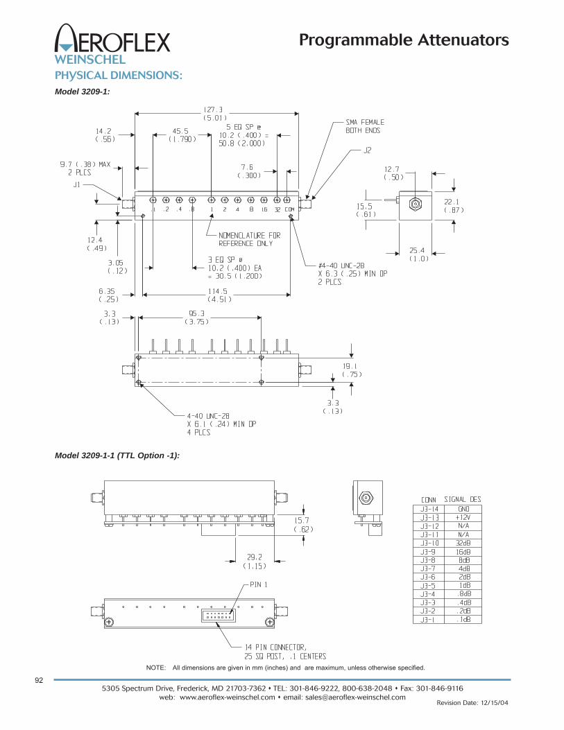
PHYSICAL DIMENSIONS:
NOTE: All dimensions are given in mm (inches) and are maximum, unless otherwise specified.
Model 3209-1:
Model 3209-1-1 (TTL Option -1):

935305 Spectrum Drive, Frederick, MD 21703-7362 TEL: 301-846-9222, 800-638-2048 Fax: 301-846-9116
web: www.aeroflex-weinschel.com email: [email protected] Date: 12/15/04
Programmable Attenuators
SpecificationsNOMINAL IMPEDANCE: 50 ΩFREQUENCY RANGE:dc to 2.0 GHz: 3200T-1, 3200T-2, 3201T-1, 3201T-2,
3205T-1, 3205T-2, 3205T-3, 3206T-1, 3209T-1
dc to 3.0 GHz: 3200T-1E, 3200T-2E, 3201T-1E, 3205T-3E, 3206T-1E, 3209T-1E
DescriptionThis line of intelligent programmable step attenuators with abuilt-in digital interface are designed to simplify the controland integration of these devices into subsystem and benchapplications. This series of Programmable Step Attenuatorsis designed for use in automatic test equipment and OEMsystems operating in the dc to 3 GHz frequency range.These models are available in many standard attenuationranges and cell configurations. Each cell contains a double-pole, double-throw relay that provides a minimum loss orattenuated path for the RF signal.Microstrip circuitry and special compensation techniquesproduce flat attenuation versus frequency characteristics.The microstrip construction, using thick-film circuit elements, ensures product uniformity. To minimize RF leak-age, the 3200T Series Attenuators are provided withgold-plated contact areas and feedthrough filters at eachcontrol terminal.
Model 3200T dc to 2.0 GHz
Model 3200T (E Series) dc to 3.0 GHz
Programmable Attenuators 1 Watt
with built-in Microprocessor-Based Driver
For Use with Weinschel 8210A Controller
Features
o Widest Selection of Attenuation Ranges & Steps Sizes
o Available Express Models: 3200T-13206T-1
Other models may be available for Express delivery.o Built-In TTL\CMOS Interface Driver Circuitryo High Quality Construction and Connectorso Special Configurations Available Upon Request
- Custom Cell/Step Size Configurations- 3.0 GHz and Higher Frequencies
Model NO. Attenuation CellNumber Cells Range/Steps Increments
(dB) (dB)
3200T-1 8 127/1 1, 2, 4, 8, 16, 32, 64*3200T-1E
3200T-2 8 63.75/0.25 0.25, 0.5, 1, 2, 4, 8,3200T-2E 16, 32
3201T-1 5 31/1 1, 2, 4, 8, 163201T-1E
3201T-2 5 120/10 10, 20, 30, 60**
3205T-1 4 70/10 10, 20, 20, 20
3205T-2 4 55/5 5, 10, 20, 20
3205T-3 4 1.5/0.1 0.1, 0.2, 0.4, 0.83205T-3E
3206T-1 6 63/1 1, 2, 4, 8, 16, 323206T-1E
3209T-1 10 64.5/0.1 0.1, 0.2, 0.4, 0.8, 1,3209T-1E 2, 4, 8, 16, 32*64 dB cell comprised of two 32 dB cells**60 dB cell comprised of two 30 dB cells
CELL CONFIGURATIONS:
INCREMENTAL ATTENUATION ACCURACY:Frequency AccuracyRange (GHz)
dc - 0.5 + 0.2 dB or 0.5%0.5 - 1 + 0.2 dB or 1.0%1 -3 + 0.3 dB or 2.0%
MONOTONICITY: dc to 3.0 GHzINCREMENTAL TEMPERATURE COEFFICIENT:
30 and 32 dB Cells: 0.00005 dB/dB/°CAll other cells: 0.00002 dB/dB/°C
MAXIMUM SWR:Freq 3200T-1 3200T-1E 3201T-X 3201T-1E 3209T-1 3209T-1ERange 3200T-2 3200T-2E 3205T-X 3205T-3E(GHz) 3206T-X 3206T-1E
dc - 0.2 1.30 1.25 1.30 1.25 1.35 1.350.2 - 1 1.25 1.25 1.25 1.25 1.35 1.351 - 2 1.35 1.25 1.35 1.25 1.35 1.352 - 3 - - - 1.40 - - - 1.35 - - - 1.45
www.sicklesonline.com
E PX R E SS
800-542-4457

5305 Spectrum Drive, Frederick, MD 21703-7362 TEL: 301-846-9222, 800-638-2048 Fax: 301-846-9116
web: www.aeroflex-weinschel.com email: [email protected]
94
Revision Date: 12/15/04
Programmable Attenuators
POWER RATING: 1 watt average to 25°C ambient tem-perature, derated linearly to 0.25 watt @ 71°C. 50 wattspeak (5 µsec pulse width; 1% duty cycle)POWER COEFFICIENT: < 0.005 dB/dB/watt
RATED SWITCH LIFE: 5 million cycles operations per cell@ 0 dBmCYCLING RATE: 5 Hz maximum per relayDRIVER INTERFACE:Input Supply Voltage: +12.0 to +15. VControl Signals: TTL/CMOS compatibleInterface Modes: parallel / serialDC Characteristics (at 25 °C): Parameter SpecificationVIL Low-level input V: -0.5V min, 0.8V maxVIH High-level input V: 2.0V min, 5.25V maxIPU Pullup current 50 µA min, 400 µA maxVIN Supply Voltage: +12.0 to +15.0VIIN Supply current: 25 mA
(digital section)ICELL Supply current: 15 mA (2 GHz Units)
(per cell) continuous 30 mA (3 GHz Units)
TEMPERATURE RANGE (Operating): -20°C to +70°CTEST DATA: Test data is available at additional cost.CONNECTORS: SMA female connectors per MIL-STD-348interface dimensions - mate nondestructively with MIL-C-39012 connectors. INTERFACE CONNECTOR: 14 pin .025 square postheader on .1 center. Mates with Amp connector 746285-2 orequivalent.CONSTRUCTION:
Housing: AluminumConnectors: Stainless steel body and beryllium
copper contacts.WEIGHT: 3200T-X 165 g (8.4 oz)
3201T-X 132 g (7.3 oz)3205T-X 132 g (7.3 oz)3206T-X 132 g (7.3 oz)3209T-X 218 g (9.7 oz)
ACCESSORIESProgrammable Attenuator/Switch Controller: The Model8210A Programmable Attenuator/Switch Controller providesa flexible, low cost solution for the operation of programma-ble step attenuators and other electromechanical devicesunder computer control. Designed to interface to Aeroflex /Weinschel's intelligent programmable attenuators, the8210A represents a new concept in device control applica-tions for bench test and subsystem designs. The 8210Aprovides a high-level interface from various industry stan-dard communications interfaces, including IEEE-488 andRS232/RS422/RS485, to the programmable attenuator’sserial Driver Interface Bus.
CONTROL CONFIGURATION
These programmable attenuators feature an internal micro-controller-based driver that provides a TTL-level digitalinterface for control of the attenuator relays. This card sim-plifies operation and interfacing requirements, while at thesame time providing for greatly enhanced flexibility overpast designs. User-selectable modes of operation includeboth parallel and serial bus. The parallel mode provides asimple, one-bit per relay on/off control with internal pullupsfor use primarily in single attenuator applications. This modeallows the attenuator to be controlled via a variety of meth-ods, such as a TTL-level digital output port, or mechanicaltoggle switches. The device bus provides a two-wire serialbus structure and protocol for connecting a number ofdevices to a single host control interface, suitable for use inlarger system and sub-system applications. The digitalinterface contains non-volatile configuration memory that isused to hold a wide variety of attenuator and driver-depen-dent parameters, including serial number, attenuator cell dBvalues, relay configurations, and switching requirements,which are all accessible via the digital interface. In either operational mode, the microcontroller enters anidle condition during periods of inactivity, turning off all on-board clocks, reducing EMI concerns, and loweringpower consumption. On-board regulation for the digital circuitry allows the attenuator to operate from a single inputsupply voltage.
Specifications - Con’t
MAXIMUM INSERTION LOSS (dB):Frequency 3200T-1 3200T-1E 3201-1 3205T-X 3201T-1E 3206T-1 3206T-1E 3209T-1 3209T-1ERange (GHz) 3200T-2 3200T-2E 3201-2 3205T-3E
dc - 0.5 2.80 2.00 1.80 1.80 1.25 2.00 1.50 3.50 3.000.5 - 1.0 3.50 2.70 2.40 2.30 1.75 2.70 2.00 4.50 3.501.0 - 1.5 4.25 3.00 3.00 2.80 2.25 3.30 2.50 5.60 4.001.5 - 2.0 4.75 3.50 3.75 3.30 2.50 4.00 2.80 6.70 4.502.0-3.0 - - - 4.30 - - - - - - 3.40 - - - 3.70 - - - 5.50

955305 Spectrum Drive, Frederick, MD 21703-7362 TEL: 301-846-9222, 800-638-2048 Fax: 301-846-9116
web: www.aeroflex-weinschel.com email: [email protected] Date: 12/15/04
Programmable Attenuators
PHYSICAL DIMENSIONS:
"D"
NOTE: All dimensions are given in mm (inches) and are maximum, unless otherwise specified.
Model No. No. Cells A B C D3200T-X 8 101.6 (4.0) 34.8 (1.37) 88.9 (3.50) 95.2 (3.75)
3201T-X 5/4 76.2 (3.00) 22.1 (0.87) 63.5 (2.50) 69.8 (2.75)
3205T-X 4 72.4 (2.85) 20.3 (0.80) 46.2 (1.82) 52.6 (2.07)
3206T-X 6 81. 3+0.5 24.0 (0.98) 68.6 (2.70) 75.18 (2.96) (3.20+0.02
Model 3200T, 3201T, 3205T, & 3206T:
Model 3209T:

5305 Spectrum Drive, Frederick, MD 21703-7362 TEL: 301-846-9222, 800-638-2048 Fax: 301-846-9116
web: www.aeroflex-weinschel.com email: [email protected]
96
Revision Date: 12/15/04
Programmable Attenuators
Model 3250 & 3250T dc to 1.0 GHz
Programmable Attenuators 1 Watt
with optional TTL Interface 75 Ω
T Series for use with Weinschel 8210A Controller
Features
o Cost Effective design for Wireless/CellularApplications
o Available Express Models: 3250T-63Other models may be available for Express delivery.
o Optional Built-in Interfaceo Custom Configurations including bus controlled
attenuator subsystems
SpecificationsNOMINAL IMPEDANCE: 75 ΩFREQUENCY RANGE: dc to 1.0 GHz:
CELL CONFIGURATIONS:Model NO. Attenuation Cell
Number Cells Range/Steps Increments(dB) (dB)
3250-63 6 63/1 1, 2, 4, 8, 16, 32
INCREMENTAL ATTENUATION ACCURACY:Frequency AccuracyRange (GHz) dc - 0.5 + 0.3 dB or 2.0%0.5 - 1.0 + 0.4 dB or 2.0%
MAXIMUM SWR:Frequency Range (GHz) SWR
dc - 0.5 1.600.5 - 1.0 1.40
Frequency Range (GHz) Loss (dB)
dc - 0.5 2.250.5 - 1.0 5.00
RATED SWITCH LIFE: 5 million operations per cell (typ)SWITCHING TIME: 8 msec. maximum @ nominal ratedvoltage.CYCLING RATE: 5 Hz maximumOPERATING VOLTAGE: +11V to +16V
+12V to +17V (TTL opt -1)OPERATING CURRENT: 16 mA maximum per cell TEMPERATURE RANGE (Operating): -40 to +70°CPOWER RATING: 1 watt average, 50 watts peak (5 µsecpulse width; 1% duty cycle)CONNECTORS: BNC female connectors per MIL-STD-348 interface dimensions - mate nondestructively withMIL-C-39012 connectors. CONTROL TERMINALS: 0.040 inch. (1 mm) diametersolderable leadsCONSTRUCTION:
Housing: AluminumConnectors: Nickel plated brass body and
beryllium copper contacts.WEIGHT: 3250 140 g (4.5 oz)
3250T 189 g (4.9 oz)
MAXIMUM CHARACTERISTIC ZERO LOSS (dB):www.sicklesonline.com
E PX R E SS
800-542-4457
ACCESSORIES
Programmable Attenuator/Switch Controller: The Model8210A Programmable Attenuator/Switch Controller providesa flexible, low cost solution for the operation of programma-ble step attenuators and other electromechanical devicesunder computer control. Designed to interface to Aeroflex /Weinschel's intelligent programmable attenuators, the8210A represents a new concept in device control applica-tions for bench test and subsystem designs. The 8210Aprovides a high-level interface from various industry stan-dard communications interfaces, including IEEE-488 andRS232/RS422/RS485, to the programmable attenuator'sserial Driver Interface Bus.

975305 Spectrum Drive, Frederick, MD 21703-7362 TEL: 301-846-9222, 800-638-2048 Fax: 301-846-9116
web: www.aeroflex-weinschel.com email: [email protected] Date: 12/15/04
Programmable Attenuators
MODEL NUMBER DESCRIPTION:Example:
3250* - XX - X
*Add T to Basic Model Number when ordering Digital ControlCircuitry.
BasicModelNumber
AttenuationValue (dB)
TTL Option(Add -1)Example: 3250-63-1
Figure 1. Built-In Driver Circuitry
CONTROL CONFIGURATION: Standard Unit: One terminal is connected to case groundand the remaining terminals are provided for activation ofindividual cells. Attenuation is fail-safe to "0" setting in theabsence of a control voltage. Application of a voltage (+) toa particular cell causes it to switch to the attenuate position. Units with TTL Option: Units with this options are suppliedwith a very low profile connectorized TTL interface boardmounted directly to the control terminals. This TTL interfaceoption is available with a 10 pin ribbon cable connector andis supplied with a mating connector. Refer to PhysicalDimensions for mating connector pin/wiring details. Twowires are specified for supply voltage and ground. Theremaining wires will accept TTL control signals to activate orde-activate a particular attenuation cell. A TTL high willenergize a cell to the high attenuation state, whereas a TTLlow will maintain a cell in its zero attenuation state.To order 3250 Series Attenuators with this option add -1 tobasic model number for ribbon cable connector. Example:Model 3250-63 with a TTL interface would be 3250-63-1. Note: Control is non-latching and requires a continuouscontrol signal for the period of time in which attenuation isrequired.TTL DRIVER SPECIFICATIONS:INTERFACE CONNECTOR: Option -1: 10 pin .025 squarepost header on .1 center, mates with Amp connector746285-1 or equivalentINPUT VOLTAGE: VIN High= +2.0V minimum
+5.0V typicalVcc maximum
VIN Low = 0 minimum0.8 maximum
INPUT CURRENT: IIN (VIN=2.4 V) = 55 µAIIN (VIN=3.85 V) = 280 µA
SUPPLY CURRENT: ICC=25 mA maximum per cell
SUPPLY VOLTAGE: VCC=+12.0 to +15 V
TEMPERATURE RANGE (Operating): -40 to +70 °CUnits with driver Circuitry (Figure 1): Model 3250T-63features an internal microcontroller-based driver that pro-vides a TTL-level digital interface for control of theattenuator relays. This card simplifies operation and inter-facing requirements, while at the same time providing forgreatly enhanced flexibility over past designs. User-selec-table modes of operation include both parallel and serialbus. The parallel mode provides a simple, one-bit per relayon/off control with internal pullups for use primarily in singleattenuator applications. This mode allows the attenuator tobe controlled via a variety of methods, such as a TTL-leveldigital output port, or mechanical toggle switches. The built-in driver bus provides a two-wire serial bus structure andprotocol for connecting a number of devices to a single hostcontrol interface, suitable for use in larger system and sub-system applications. This programmable attenuatorcontains non-volatile configuration memory that is used tohold a wide variety of attenuator and driver-dependent para-
Non-VolatileConfiguration
Memory
Single-ChipMicrocontroller
RelayDrivers
TTL/CMOSCompatibleDigital Interface
+12 to+15 VInput
ToAttenuator
Relays
EMIFilters
+5 VRegulator
meters, including serial number, attenuator cell dB values,relay configurations, and switching requirements, which areall accessible via the digital interface.Digital Driver Interface Specifications:
Input Supply Voltage: +12.0 to +15.0VControl Signals: TTL/CMOS compatible
Interface Modes: parallel/ I2C serialDC Characteristics (at 25°C): Digital Interface:Parameter SpecificationVIL Low Level input: -0.5 min, 0.8V maxVIH High Level input: 2.0 min, 5.25V maxIPU Pullup Current 50 µA min, 400 µA maxPower Supply:VIN Supply Voltage: +12.0 to +15.0VIIN Supply current: 25 mAICELL Supply Current: 150 mA (per cell, switching)
TEMPERATURE: -20° to +70°C operating-55° to +85°C nonoperating
INTERFACE CONNECTOR: 14 pin .025 square postheader on .1 center. Mates with Amp connector 746285-2 orequivalent (one mating connector included with each unit).

5305 Spectrum Drive, Frederick, MD 21703-7362 TEL: 301-846-9222, 800-638-2048 Fax: 301-846-9116
web: www.aeroflex-weinschel.com email: [email protected]
98
Revision Date: 12/15/04
Programmable Attenuators
BNC CONNECTORSBOTH ENDS
Aeroflex / Weinschel
PHYSICAL DIMENSIONS:
Model 3250:
Model 3250 w/TTL Option -1:
TTL Conn 3250-63-1PIN No. (J3) dB (Cell)
1 NC
2 NC
3 32
4 1
5 2
6 4
7 8
8 16
9 COM
10 +Vcc
NC = Not Connected
Control Connector J3 Pin Locations:
NOTE: All dimensions are given in mm (inches) and are maximum, unless otherwise specified.
995305 Spectrum Drive, Frederick, MD 21703-7362 TEL: 301-846-9222, 800-638-2048 Fax: 301-846-9116
web: www.aeroflex-weinschel.com email: [email protected] Date: 12/15/04
Programmable Attenuators
BNC CONNECTORSBOTH ENDS
Aeroflex / Weinschel
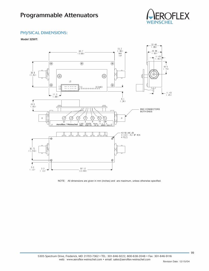
PHYSICAL DIMENSIONS:
Model 3250T:
NOTE: All dimensions are given in mm (inches) and are maximum, unless otherwise specified.

5305 Spectrum Drive, Frederick, MD 21703-7362 TEL: 301-846-9222, 800-638-2048 Fax: 301-846-9116
web: www.aeroflex-weinschel.com email: [email protected]
100
Revision Date: 12/11/05
Programmable Attenuators
Models 3406 & 3408 dc to 6.0 GHz
Programmable Attenuators 1 Watt
Ideal for Wireless/Test Applications
Model NO. Attenuation CellNumber Cells Range/Steps Increments
(dB) (dB)
3406-55 6 55/1 1, 2, 4, 8, 16, 24
3408-55.75 8 55.75/0.25 0.25, 0.5, 1, 2, 4, 8, 16, 24
3408-103 8 103/1 1, 2, 4, 8, 16, 24, 48*
*48 dB cell comprised of two 24 dB cells
CELL CONFIGURATIONS:
DescriptionThe 3400 Series Programmable Step Attenuators aredesigned for use in automatic test equipment and OEMsystems operating in the dc to 6 GHz frequency range. Thisseries is available in many standard attenuation ranges andcell configurations. Custom designed configurations areavailable upon request. Each cell contains a double-pole,double-throw relay that provides a zero path or attenu-ated path for the RF signal.Microstrip circuitry and special compensation techniquesproduce flat attenuation versus frequency characteristics.The microstrip construction, using thin-film circuit ele-ments, ensures product uniformity. To minimize RFleakage, the 3400 Series Attenuators are provided withgold-plated contact areas and feedthrough filters at eachcontrol terminal.
Features
o Higher Frequency range to 6 GHz.o Wide Selection of Attenuation Ranges & Step
Sizes- 0 to 55 dB in 1 dB steps- 0 to 103 dB in 1 dB steps- 0 to 55.75 in 0.25 dB steps
o High Quality Construction & Connectorso Special Configurations Available Upon Request
SpecificationsNOMINAL IMPEDANCE: 50 ΩFREQUENCY RANGE: dc to 6.0 GHz
INCREMENTAL ATTENUATION ACCURACY:Frequency AccuracyRange (GHz)
dc - 3 +0.3 dB or 2% whichever is greater3 - 6 +0.4 dB or 3% whichever is greater
MAXIMUM SWR:Frequency Range (GHz) SWR
dc - 3 1.303 - 6 1.45
MONOTONICITY: dc to 6.0 GHzPOWER RATING: 1 watt average to 25°C ambient tem-perature, derated linearly to 0.25 watt @ 70°C. 50 wattspeak (5 μsec pulse width; 1% duty cycle)POWER COEFFICIENT: <0.005 dB/dB/watt
RATED SWITCH LIFE: 5 million cycles operations per cell@ 0 dBmSWITCHING TIME: 6 msec. maximum at nominal ratedvoltageRELEASE TIME: 5 msec maximumCYCLING RATE: 5 Hz maximum per relayOPERATING VOLTAGE: +12V (+13V maximum; +9V min-imum) OPERATING CURRENT: 17 mA typical per cell @ +12VTEMPERATURE RANGE (Operating): -30°C to +70°CTEST DATA: Test data is available at additional cost.
MAXIMUM INSERTION LOSS (dB):Frequency 3206-55 3408-55.75Range (GHz) 3408-103
dc - 3 2.60 3.403 - 6 3.80 5.00

1015305 Spectrum Drive, Frederick, MD 21703-7362 TEL: 301-846-9222, 800-638-2048 Fax: 301-846-9116
web: www.aeroflex-weinschel.com email: [email protected] Date: 12/11/05
Programmable Attenuators
Specifications - Con’t
CONNECTORS: SMA female connectors per MIL-STD-348interface dimensions - mate nondestructively with MIL-C-39012 connectors. CONTROL TERMINALS: 0.040 inch. (1 mm) diameter solderable leads. May be used with PC board sockets/receptacles. CONSTRUCTION:
Housing: AluminumConnectors: Stainless steel body and beryllium
copper contacts.Control terminals: Brass/Copper, Silver plated
WEIGHT (Typical): 3406-X: 99 g (3.5 oz)3408-X: 135 g (4.8 oz)
CONTROL CONFIGURATION: One terminal is connected to case ground and the remain-ing terminals are provided for activation of individual cells.Attenuation is fail-safe to "0" setting in the absence of a con-trol voltage. Application of a voltage (+) to a particular cellcauses it to switch to the attenuate position. Note: Control is non-latching and requires a continuouscontrol signal for the period of time in which attenuation isrequired.
A
B
C
D
Aeroflex / Weinschel
PHYSICAL DIMENSIONS:
NOTE: All dimensions are given in mm (inches) and are nominal, unless otherwise specified.
Model No. No. Cells A B C D3408-X 8 136.1 (5.36) 123.4 (4.86) 7 EQ SPCS @ 15.20 (.60) = 106.7 (4.20) 128.5 (5.06)
3406-X 6 105.7 (3.66) 93.0 (3.66) 5 EQ SPCS @ 15.20 (.60) =76.0 (3.00) 98.0 (3.86)

5305 Spectrum Drive, Frederick, MD 21703-7362 TEL: 301-846-9222, 800-638-2048 Fax: 301-846-9116
web: www.aeroflex-weinschel.com email: [email protected]
1
Revision Date: 12/13/05
Programmable Attenuators
Models 3406T & 3408T dc to 6.0 GHz
Programmable Attenuators 1 Watt
with built-in Microprocessor-Based Driver
For Use with Weinschel 8210A Controller
Model NO. Attenuation CellNumber Cells Range/Steps Increments
(dB) (dB)
3406T-55 6 55/1 1, 2, 4, 8, 16, 24
3408T-55.75 8 55.75/0.25 0.25, 0.5, 1, 2, 4, 8, 16, 24
3408T-103 8 103/1 1, 2, 4, 8, 16, 24, 48*
*48 dB cell comprised of two 24 dB cells
CELL CONFIGURATIONS:
DescriptionThis line of intelligent programmable step attenuators with abuilt-in digital interface are designed to simplify the controland integration of these devices into subsystem and benchapplications. This series of Programmable Step Attenuatorsis designed for use in automatic test equipment and OEMsystems operating in the dc to 6 GHz frequency range.These models are available in many standard attenuationranges and cell configurations. Each cell contains a double-pole, double-throw relay that provides a minimum loss orattenuated path for the RF signal.Microstrip circuitry and special compensation techniquesproduce flat attenuation versus frequency characteristics.The microstrip construction, using thick-film circuit elements, ensures product uniformity. To minimize RF leak-age, the 3400T Series Attenuators are provided withgold-plated contact areas and feedthrough filters at eachcontrol terminal.
Features
o Higher Frequency range to 6 GHz.o Wide Selection of Attenuation Ranges & Step
Sizes- 0 to 55 dB in 1 dB steps- 0 to 103 dB in 1 dB steps- 0 to 55.75 in 0.25 dB steps
o High Quality Construction & Connectorso Built-In TTL\CMOS Interface Driver Circuitryo Special Configurations Available Upon Request
SpecificationsNOMINAL IMPEDANCE: 50 ΩFREQUENCY RANGE: dc to 6.0 GHz
INCREMENTAL ATTENUATION ACCURACY:Frequency AccuracyRange (GHz)
dc - 3 +0.3 dB or 2% whichever is greater3 - 6 +0.4 dB or 3% whichever is greater
MAXIMUM SWR:Frequency Range (GHz) SWR
dc - 3 1.303 - 6 1.45
MONOTONICITY: dc to 6.0 GHzPOWER RATING: 1 watt average to 25°C ambient tem-perature, derated linearly to 0.25 watt @ 70°C. 50 wattspeak (5 μsec pulse width; 1% duty cycle)POWER COEFFICIENT: <0.005 dB/dB/watt
RATED SWITCH LIFE: 5 million cycles operations per cell@ 0 dBmSWITCHING TIME: 6 msec. maximum at nominal ratedvoltageRELEASE TIME: 5 msec maximumSWITCHING SPEED: 5 Hz maximum per relayOPERATING VOLTAGE: +12V (+13V maximum; +9V min-imum) OPERATING CURRENT: 17 mA typical per cell @ +12VTEMPERATURE RANGE (Operating): -30°C to +70°CTEST DATA: Test data is available at additional cost.
MAXIMUM INSERTION LOSS (dB):Frequency 3206-55 3408-55.75Range (GHz) 3408-103
dc - 3 2.60 3.403 - 6 3.80 5.00

25305 Spectrum Drive, Frederick, MD 21703-7362 TEL: 301-846-9222, 800-638-2048 Fax: 301-846-9116
web: www.aeroflex-weinschel.com email: [email protected] Date: 12/13/05
Programmable Attenuators
Specifications - Con’t
CONNECTORS: SMA female connectors per MIL-STD-348interface dimensions - mate nondestructively with MIL-C-39012 connectors. INTERFACE CONNECTOR: 14 pin .025 square postheader on .1 center. Mates with Amp connector 746285-2 orequivalent.CONSTRUCTION:
Housing: AluminumConnectors: Stainless steel body and beryllium
copper contacts.Control terminals: Brass/Copper, Silver plated
WEIGHT (Typical): 3406T-X: 99 g (3.5 oz)3408T-X: 135 g (4.8 oz)
DRIVER INTERFACE:Parameter SpecificationVIL Low-level input V: -0.5V min, 0.8V maxVIH High-level input V: 2.0V min, 5.25V maxIPU Pullup current: 50 μA min, 400 μA maxVIN Supply Voltage: +12.0 to +15.0VIIN Supply current: 25 mA
(digital section)ICELL Supply current: 16.6 mA @ 12V
“A”
“B”
“C”
“D”
PHYSICAL DIMENSIONS:
NOTE: All dimensions are given in mm (inches) and are nominal, unless otherwise specified.
Model No. No. Cells A B C D3408T-X 8 136.1 (5.36) 123.4 (4.86) 7 EQ SPCS @ 15.20 (.60) = 106.7 (4.20) 128.5 (5.06)
3406T-X 6 105.7 (3.66) 93.0 (3.66) 5 EQ SPCS @ 15.20 (.60) =76.0 (3.00) 98.0 (3.86)

5305 Spectrum Drive, Frederick, MD 21703-7362 TEL: 301-846-9222, 800-638-2048 Fax: 301-846-9116
web: www.aeroflex-weinschel.com email: [email protected]
102
Revision Date: 3/23/05
Programmable Attenuators
Model 150T dc to 18.0 GHz
Model 151T dc to 4.0 GHz
Model 152T dc to 26.5 GHz
Relay Switched Programmable Attenuators,
with built-in Microprocessor-Based Driver
For Use with Weinschel 8210A Controller
DescriptionAeroflex / Weinschel’s line of intelligent programmable stepattenuators with a built-in TTL interface (Figure 1). Thesemodels are designed to simplify the control and integrationof these devices into subsystem and bench applications.These intelligent attenuators offer the same long reliableoperation with exceptional accuracy and repeatability aswith our other 150 Series Programmable Attenuators. Theyprovide programmable adjustments of RF signal levels inprecise steps of 1 dB, 5 dB, 10 dB, or with custom stepsavailable. Each attenuator consists of a cascaded assemblyof switched attenuator cells and a internal TTL interface.
The attenuator elements located in the attenuator cell arecreated by a thin-film process which provides exceptionallong-term stability, low power and temperature coefficients.This series of step attenuators uses a reed switching struc-ture that provides rapid switching together with low insertionloss. BUILT-IN DRIVER CIRCUITRY: These programmableattenuators feature an internal microcontroller-based driverthat provides a TTL-level digital interface for control of theattenuator relays. This card simplifies operation and inter-facing requirements, while at the same time providing forgreatly enhanced flexibility over past designs. User-selec-table modes of operation include both parallel and serialbus. The parallel mode provides a simple, one-bit per relayon/off control with internal pullups for use primarily in singleattenuator applications. This mode allows the attenuator tobe controlled via a variety of methods, such as a TTL-leveldigital output port, or mechanical toggle switches. Thedevice bus provides a two-wire serial bus structure and pro-tocol for connecting a number of devices to a single hostcontrol interface, suitable for use in larger system and sub-system applications. The driver interface containsnon-volatile configuration memory that is used to hold awide variety of attenuator and driver-dependent parame-ters, including serial number, attenuator cell dB values,relay configurations, and switching requirements, which areall accessible via the digital interface. This frees the systemdesigner from such low-level details, allowing faster inte-gration. In either operational mode, the microcontrollerenters an idle condition during periods of inactivity, turningoff all on-board clocks, reducing EMI concerns, and lower-ing power consumption. On-board regulation for the digitalcircuitry allows the programmable attenuator to operatefrom a single input supply voltage.
Other features include:
o Wide Variety of Frequency & Attenuation Rangeso Broadband Frequency Coverageo High Accuracy and Repeatabilityo Long Life, 5 Million Cycles Per Cello Common 14 pin Interface Connectoro Custom Attenuation Ranges
For additional information on the 150 Series, visit our website @ www.aeroflex-weinschel.com/programmables.htm
Non-VolatileConfiguration
Memory
Single-ChipMicrocontroller
RelayDrivers
TTL/CMOSCompatibleDigital Interface
+12 to+15 VInput
ToAttenuator
Relays
EMIFilters
+5 VRegulator
Figure 1. Built-In Driver Circuitry
DC-DCConverter
www.sicklesonline.com
E PX R E SS
800-542-4457

1035305 Spectrum Drive, Frederick, MD 21703-7362 TEL: 301-846-9222, 800-638-2048 Fax: 301-846-9116
web: www.aeroflex-weinschel.com email: [email protected] Date: 3/23/05
Programmable Attenuators
Frequency (GHz)APPLICABLE MODELS dc-4 4-18 18-26.5
151T-11, 151T-15, 151T-31, 1.50 - - - - - -151-62T, 151T-75, 151T-110
150T-11, 150T-15, 150T-31 1.50 1.90 - - -150T-62, 150T-75, 150T-110
151T-70 (3 cell) 1.35 - - - - - -
150T-70 (3 cell) 1.35 1.70 - - -
152AT-70 (3 cell) 1.40 1.70 1.80
152T-55, 152T-70, 152T-90 1.40 1.60 1.90
SpecificationsNOMINAL IMPEDANCE: 50 ΩFREQUENCY RANGE: Model 151T: dc to 4 GHz
Model 150T: dc to 18 GHzModel 152T: dc to 26.5 GHz
DRIVER INTERFACE:Input Supply Voltage: +12.0 to +15.0VControl Signals: TTL/CMOS compatibleInterface Modes: parallel / serialDC Characteristics (at 25 °C): Digital Interface:Parameter SpecificationVIL Low Level input: -0.5 min, 0.8V maxVIH High Level input: 2.0 min, 5.25V maxIPU Pullup Current 50 μA min, 400 μA maxPower Supply:VIN Supply Voltage: +12.0 to +15.0VIIN Supply current: 25 mAICELL Supply Current: 150 mA (per cell, switching)
POWER RATING: 1 watt average, 100 watts peak(5 μsec pulse width; 0.5% duty cycle)
TEMPERATURE: -20° to +70°C operating-55° to +85°C nonoperating
TEMPERATURE COEFFICIENT: <0.0001 dB/dB/CPOWER SENSITIVITY: <0.001 dB/dB/ WattRATED SWITCH LIFE: 5 million cycles per cellRF INPUT CONNECTORS: Rugged female 3.5 mm whichmate nondestructively with SMA male connectors per MIL-STD-39012.INTERFACE CONNECTOR: 14 pin .025 square postheader on .1 center. Mates with Amp connector 746285-2 orequivalent (one mating connector included with each unit).SWITCHING TIME: 20 msec (includes settling time)CYCLING RATE: 4 Hz max per relayCONTROL PULSE WIDTH: 20 msec (minimum) REPEATABILITY: +0.01 typical to 18 GHz
+0.05 dB typical to 26.5 GHzVIBRATION*: MIL-STD-202F, Method 204D Cond BALTITUDE*: MIL-STD-202F, Method 105C Cond B,
50,000 Ft.SHOCK*: MIL-STD -202F, Method 213B Cond B,
except 10G, 6 msecHUMIDITY*: MIL-STD-202F, Method 103B,
Cond. B (96 Hrs. @ 95%, RH).
MAXIMUM INSERTION LOSS (dB):Frequency (GHz)
APPLICABLE MODELS dc-4 4-18 18-26.5
151T-11, 151T-15, 151T-75, 0.90 - - - - - -151T-110
150T-11, 150T-15, 150T-75, 0.90 2.20 - - 150T-110
151T-31, 151T-62 (5 cell) 1.10 ---- ----
150T-31, 150T-62 (5 cell) 1.10 2.60* ----
151T-70 (3 cell) 0.70 - - - - - -
150T-70 (3 cell) 0.70 1.60 - - -
152AT-70 (3 cell) 0.90 2.00 2.98
152T-55, 152T-70, 152T-90 0.90 2.00 2.98
MAXIMUM SWR (50 ΩΩ Characteristic Impedance):
Cell 11 15 31 55 62 70 70 75 90 1101 1 1 1 5 2 10 10 5 10 102 4 8 16 10 32 20 40 40 30 403 2 2 2 20 16 20 20 20 20 204 4 4 8 20 4 20 -- 10 30 405 -- -- 4 -- 8 -- -- -- -- --
CELL CONFIGURATIONS:
*4-12.4 is 1.80, 12.4-18 is 2.60
Programmable Attenuator/Switch Controller: The Model8210A Programmable Attenuator/Switch Controller providesa flexible, low cost solution for the operation of programma-ble step attenuators and other electromechanical devicesunder computer control. Designed to interface to Aeroflex /Weinschel's intelligent programmable attenuators, the8210A represents a new concept in device control applica-tions for bench test and subsystem designs. The 8210Aprovides a high-level interface from various industry stan-dard communications interfaces, including IEEE-488 andRS232/RS422/RS485, to the programmable attenuator'sserial Driver Interface Bus.OPTIONAL TEST Data: Test Data is available at an addi-tional cost for all programmable step attenuator models.Standard test Data can be provided in 250 MHz steps for alldc-4 GHz models and in 500 MHz steps for dc-18 and dc-26.5 GHz models.
ACCESSORIES
WEIGHT: 5 Cell 350 g (12 oz)4 Cell 290 g (9.0 oz)3 Cell 230 g (8.0 oz)

Frequency Attenuation Setting (dB)Range (GHz) 5 10 15 20 25 30 35 40 45 50 55
dc-4 0.2 0.3 0.4 0.4 0.4 0.6 0.6 0.7 0.7 0.8 1.0
4-12.4 0.3 0.4 0.5 0.5 0.5 0.7 0.8 0.9 0.9 1.0 1.3
12.4-18 0.4 0.4 0.5 0.5 0.5 0.8 1.0 1.1 1.1 1.2 1.6
18-26.5 0.5 0.5 0.6 0.6 0.6 0.9 1.2 1.4 1.4 1.5 2.0
Model 152T-55:
Frequency Attenuation Setting (dB)Range (GHz) 10 20 30 40 50 60 70 80 90 100 110
dc-4 0.2 0.3 0.5 0.7 0.9 1.0 1.2 1.4 1.6 1.7 1.9
4-12.4 0.4 0.7 0.9 1.2 1.5 1.8 2.1 2.4 2.7 3.0 3.0
12.4-18 0.4 0.8 1.2 1.6 2.0 2.4 2.8 3.2 3.6 4.0 4.0
18-26.5 0.6 0.7 0.9 1.5 1.6 2.2 2.9 --- --- --- ---
Model 150T/151T-70, 150T/151T-110, 152AT-70:
Frequency Attenuation Setting (dB)Range (GHz) 2 4 6 8 10 12 14 16 18 20 22 24 26 28 30 32
dc-4 0.3 0.3 0.3 0.4 0.4 0.5 0.5 0.5 0.5 0.5 0.5 0.5 0.5 0.5 0.6 0.6
4-12.4 0.4 0.4 0.4 0.5 0.5 0.6 0.6 0.6 0.7 0.7 0.7 0.8 0.8 0.8 0.8 0.8
12.4-18 0.5 0.5 0.5 0.6 0.6 0.6 0.8 0.8 0.8 0.8 0.8 1.0 1.0 1.0 1.2 1.2
Model 150T/151T-62:
Frequency Attenuation Setting (dB)Range (GHz) 1 2 3 4 5 6 7 8 9 10 11 12 13 14 15
dc-4 0.2 0.2 0.3 0.3 0.3 0.3 0.4 0.4 0.4 0.4 0.5 0.5 0.5 0.5 0.5
4-12.4 0.3 0.3 0.4 0.4 0.5 0.5 0.6 0.6 0.6 0.6 0.7 0.7 0.7 0.7 0.7
12.4-18 0.5 0.6 0.6 0.6 0.6 0.7 0.7 0.7 0.7 0.8 0.8 0.8 0.8 0.8 0.8
18-26.5 0.5 0.6 0.7 0.8 0.9 0.9 0.9 1.0 1.1 1.1 1.1 1.1 1.1 1.1 1.1
Model 150T/151T/152T-11 & 150T/151T/152T-15:
Frequency Attenuation Setting (dB)Range (GHz) 5 10 15 20 25 30 35 40 45 50 55 60 65 70 75
dc-4 0.2 0.2 0.4 0.4 0.5 0.5 0.7 0.7 0.9 0.9 1.1 1.1 1.2 1.2 1.4
4-12.4 0.3 0.3 0.6 0.6 0.9 0.9 1.2 1.2 1.5 1.5 1.8 1.8 2.1 2.1 2.1
12.4-18 0.4 0.4 0.8 0.8 1.2 1.2 1.6 1.6 2.0 2.0 2.4 2.4 2.8 2.8 2.8
Model 150T/151T-75:
Frequency Attenuation Setting (dB)Range (GHz) 34 36 38 40 42 44 46 48 50 52 54 56 58 60 62
dc-4 0.6 0.6 0.7 0.7 0.7 0.8 0.8 0.8 0.9 0.9 0.9 1.0 1.0 1.0 1.2
4-12.4 1.0 1.0 1.1 1.1 1.3 1.4 1.4 1.4 1.5 1.6 1.6 1.6 1.8 1.8 1.8
12.4-18 1.4 1.4 1.6 1.6 1.8 1.8 2.0 2.0 2.0 2.2 2.2 2.2 2.4 2.4 2.4
Frequency Attenuation Setting (dB)Range (GHz) 1 2 3 4 5 6 7 8 9 10 11 12 13 14 15 16
dc-4 0.2 0.2 0.3 0.3 0.3 0.3 0.4 0.4 0.5 0.4 0.5 0.5 0.5 0.5 0.5 0.5
4-12.4 0.3 0.3 0.4 0.4 0.5 0.5 0.6 0.6 0.7 0.6 0.7 0.7 0.7 0.7 0.7 0.7
12.4-18 0.5 0.5 0.6 0.6 0.6 0.6 0.7 0.7 0.8 0.8 0.8 0.8 0.8 0.8 0.88 0.8
Model 150T/151T-31:
Frequency Attenuation Setting (dB)Range (GHz) 17 18 19 20 21 22 23 24 25 26 27 28 29 30 31
dc-4 0.5 0.6 0.6 0.6 0.6 0.6 0.6 0.6 0.7 0.7 0.7 0.7 0.7 0.8 0.8
4-12.4 0.8 0.8 0.9 0.9 0.9 0.9 0.9 0.9 1.1 1.0 1.0 1.0 1.0 1.1 1.1
12.4-18 0.9 0.9 1.0 1.0 1.0 1.0 1.1 1.1 1.2 1.2 1.2 1.2 1.2 1.3 1.3
Frequency Attenuation Setting (dB)Range (GHz) 10 20 30 40 50 60 70 80 90
dc-4 0.3 0.5 0.6 0.7 0.8 1.0 1.1 1.1 1.2
4-12.4 0.4 0.5 0.7 0.9 1.0 1.3 1.5 1.6 1.7
12.4-18 0.5 0.6 0.8 1.1 1.2 1.4 1.7 1.8 2.1
18-26.5 0.5 0.6 0.9 1.4 1.5 1.8 2.3 2.4 2.8
Model 152T-70, 152T-90:
5305 Spectrum Drive, Frederick, MD 21703-7362 TEL: 301-846-9222, 800-638-2048 Fax: 301-846-9116
web: www.aeroflex-weinschel.com email: [email protected]
104
Revision Date: 3/23/05
Programmable Attenuators
ATTENUATION ACCURACY (+dB with respect to 0 dB reference):

1055305 Spectrum Drive, Frederick, MD 21703-7362 TEL: 301-846-9222, 800-638-2048 Fax: 301-846-9116
web: www.aeroflex-weinschel.com email: [email protected] Date: 3/23/05
Programmable Attenuators
PHYSICAL DIMENSIONS:
Models 150T, 151T, & 152T:
NOTE: All dimensions are given in mm (inches) and are maximum, unless otherwise specified.
DIM A B C3 cell 83.3 (3.28) 76.2 (3.0) 101.6 (4.00)4 cell 110.7 (4.36) 103.6 (4.08) 129.2 (5.09)5 cell 136.1 (5.36) 129.1 (5.08) 154.4 (6.08)
Frequency Range NO. Attenuator Range/Step SizeCells 11/1 dB 15/1 dB 31/1 dB 55/5 dB 62/2 dB 70/10 dB 75/5 dB 90/10 dB 110/10 dB
dc-4 GHz 4 151T-11 151T-15 N/A 151T-75 N/A 151T-1103 151T-705 151T-31 151T-62
dc-18 GHz 4 150T-11 150T-15 N/A 150T-75 N/A 150T-1103 150T-705 150T-31 150T-62
dc-26.5 GHz 4 N/A NA N/A 152T-55 NA 152T-70 N/A 152T-90 152T-1103 152AT-70
EXPRESS Shipment available via www.sicklesonline.com or 800-542-4457. Other models may be available for Express delivery.
150T Series Ordering Guide...

5305 Spectrum Drive, Frederick, MD 21703-7362 TEL: 301-846-9222, 800-638-2048 Fax: 301-846-9116
web: www.aeroflex-weinschel.com email: [email protected]
106
Revision Date: 3/23/05
Programmable Attenuators
Model 150 dc to 18.0 GHz
Model 151 dc to 4.0 GHz
Model 152 dc to 26.5 GHz
Relay Switched Programmable Attenuators
DescriptionThe Model 150, 151 and 152 Programmable StepAttenuators represent the widest variety of programmableattenuators available. This attenuator design is the result ofan extensive development program and offers long reliableoperation with exceptional accuracy and repeatability.These attenuators can provide programmable adjustmentsof RF signal levels in precise steps of 1 dB, 5 dB, 10 dB, orwith custom steps available. Each attenuator consists of acascaded assembly ofswitched attenuator cells(Figure 1). The attenua-tor elements located inthe attenuator cell arecreated by a thin-filmprocess which providesexceptional long-termstability, low power andtemperature coefficients.This series uses a reedswitching structure thatprovides rapid switchingtogether with low inser-tion loss.
Other features include:
o Broadband Frequency Coverageo High Accuracy and Repeatabilityo Long Life, 5 Million Cycles Per Cello 3, 4, and 5 Cell Configurations
PROGRAMMABILITY: In each programmable stepAttenuator, solenoids are used to switch the internal resistorcard of each cell into and out of the circuit. The switching isactivated by the application of a negative control voltage tothe desired pin located in the control connector. Once thecell is switched, the solenoid is magnetically latched intoposition and is able to withstand extreme shock and vibra-tion. Internal circuitry is included to interrupt the coil currentafter switching is complete. This reduces power dissipationeven if power is continuously applied. The switching time foreach cell is rated at 20 msec maximum which includes thecontact settling time.BROADBAND ACCURACY & LOW SWR: The use ofAeroflex / Weinschel's proprietary thin-film resistor processprovides these programmable step attenuators with a highdegree of accuracy and the lowest possible SWR uncer-tainty (refer to specifications for actual values). This thin filmprocess permits the construction of circuits which are trulydistributed and without stray reactances, even at the highermicrowave frequencies. RELIABILITY: Each programmable step attenuator iscomposed of 3 to 5 (4 in most models) cells. As with allmechanical designs, usable life becomes a primary concernto the user. With this in mind Aeroflex / Weinschel backs allthese attenuators with a rated switch life of 5 million operations per cell. Standardized testing is also performedon each programmable step attenuator over its operatingfrequency range by a computer controlled Aeroflex /Weinschel Attenuation Measurement System which istraceable to NIST standards. ENVIRONMENTAL: These Model 150 Programmable StepAttenuators have undergone an extensive environmentalqualification program and have been subjected to temperature, shock, vibration, and humidity conditions perMIL-STD-202F. These programmable step attenuatorsoperate within these specifications at an ambient temperature of -20° to +75°C. Operating beyond these limits will adversely affect the accuracy and could damagethe internal circuitry.
For additional information on the 150 Series, visit our website @ www.aeroflex-weinschel.com/programmables.htm
Figure 1. Cell Schematic
www.sicklesonline.com
E PX R E SS
800-542-4457

1075305 Spectrum Drive, Frederick, MD 21703-7362 TEL: 301-846-9222, 800-638-2048 Fax: 301-846-9116
web: www.aeroflex-weinschel.com email: [email protected] Date: 3/23/05
Programmable Attenuators
VOLTAGE MODEL(S)+ 24 V with 150-XX, 151-XX, 152-XX, Viking Connector 152A-XX+ 24 V with 150-XX-1, 151-XX-1, 152-XX-1Ribbon Cable 152A-XX-1+ 5 V with 150-XX-2, 151-XX-2, 152-XX-2Viking Connector 152A-XX-2+ 5 V with 150-XX-3, 151-XX-3, 152-XX-3Ribbon Cable 152A-XX-3
Cell 1 Cell 2 Cell 3 Cell 4 Cell 5ATTN Cells ATTN ATTN ATTN ATTN ATTNValue No. Bypass Element Bypass Element Bypass Element Bypass Element Bypass Element11 dB 4 0 dB 1 dB 0 dB 4 dB 0 dB 2 dB 0 dB 4 dB - - - - - -15 dB 4 0 dB 1 dB 0 dB 8 dB 0 dB 2 dB 0 dB 4 dB - - - - - -31 dB 5 0 dB 1 dB 0 dB 8 dB 0 dB 2 dB 0 dB 16 dB 0 dB 4 dB55 dB 4 0 dB 5 dB 0 dB 10 dB 0 dB 20 dB 0 dB 20 dB - - - - - - 70 dB 4 0 dB 10 dB 0 dB 20 dB 0 dB 20 dB 0 dB 20 dB - - - - - -
3 0 dB 10 dB 0 dB 40 dB 0 dB 20 dB - - - - - - - - - - - -75 dB 4 0 dB 5 dB 0 dB 40 dB 0 dB 20 dB 0 dB 10 dB - - - - - - 90 dB 4 0 dB 10 dB 0 dB 30 dB 0 dB 20 dB 0 dB 30 dB - - - - - - 110 dB 4 0 dB 10 dB 0 dB 40 dB 0 dB 20 dB 0 dB 40 dB - - - - - - Conn Round 5 6 9 10 7 8 11 12 3 4PIN # Ribbon 13 2 3 9 11 5 4 10 8 7Wire Round Violet Yellow Orange Blue Black Green Brown White - - - - - -Color 3/4 Cell
Round Black White Green Orange Blue WHT/BLK RED/BLK GRN/BLK ORN/BLK BLU/BLK5 Cell
Ribbon Orange Yellow Blue Brown Purple Black Gray White Orange yellow
Table provides standard attenuation ranges, increments, and cell configurations for all Aeroflex / Weinschel Programmable StepAttenuators (Models 150, 151, 152, & 152A)
150 Series Cell Configurations...
SpecificationsNOMINAL IMPEDANCE: 50 ΩFREQUENCY RANGE: Model 151: dc to 4 GHz
Model 150: dc to 18 GHzModel 152: dc to 26.5 GHz
OPERATIONAL VOLTAGE: + 24V Nominal (+20V mini-mum to +30V maximum) or +5V Nominal (+4V minimum* to+7V maximum)*Minimum operating voltage derated to +4.25 V @ 55°C and furtherderated to +4.5 V @ 75°CPOWER RATING: 1 watt average, 100 watts peak
(5 μsec pulse width; 0.5% duty cycle)TEMPERATURE: -20° to +75°C operating
-55° to +85°C nonoperatingTEMPERATURE COEFFICIENT: < 0.0001 dB/dB/°CPOWER SENSITIVITY: < 0.001 dB/dB/ WattRATED SWITCH LIFE: 5 million cycles per cellRF INPUT CONNECTORS: Rugged female 3.5 mm connectors which mate nondestructively with SMA maleconnectors per MIL-STD-39012.CONTROL CONNECTOR: 12 pin Viking TNP12-101 connector with 5' cable or 14 conductor 16" ribbon cablewith connector (shown below):
SWITCHING TIME: 20 msec (includes settling time)CYCLING RATE: 4 Hz max per relayCONTROL PULSE WIDTH: 20 msec (minimum) SWITCHING CURRENT: 125 mA @ +24V per cell
300 mA @ +5V per cellREPEATABILITY: +0.01 typical to 18 GHz
+0.05 dB typical to 26.5 GHzVIBRATION: MIL-STD-202F, Method 204D Cond BALTITUDE: MIL-STD-202F, Method 105C Cond B,
50,000 Ft.SHOCK: MIL-STD -202F, Method 213B Cond B,
except 10G, 6 msecHUMIDITY: MIL-STD-202F, Method 103B,
Cond. B (96 Hrs. @ 95%, RH)EMC: Radiated interference is within the requirements ofMIL-STD-461 method RE02, VDE 0871 and CISPRPublication II.WEIGHT: 5 Cell 350 g (12 oz)
4 Cell 290 g (9.0 oz)3 Cell 230 g (8.0 oz)
VOLTAGE/CONNECTOR OPTIONS:
Ribbon Cable Models Round (Viking)Cable Models

Frequency Attenuation Setting (dB)Range (GHz) 5 10 15 20 25 30 35 40 45 50 55
dc-4 0.2 0.3 0.4 0.4 0.4 0.6 0.6 0.7 0.7 0.8 1.0
4-12.4 0.3 0.4 0.5 0.5 0.5 0.7 0.8 0.9 0.9 1.0 1.3
12.4-18 0.4 0.4 0.5 0.5 0.5 0.8 1.0 1.1 1.1 1.2 1.6
18-26.5 0.5 0.5 0.6 0.6 0.6 0.9 1.2 1.4 1.4 1.5 2.0
Model 152-55:
Frequency Attenuation Setting (dB)Range (GHz) 1 2 3 4 5 6 7 8 9 10 11 12 13 14 15
dc-4 0.2 0.2 0.3 0.3 0.3 0.3 0.4 0.4 0.4 0.4 0.5 0.5 0.5 0.5 0.5
4-12.4 0.3 0.3 0.4 0.4 0.5 0.5 0.6 0.6 0.6 0.6 0.7 0.7 0.7 0.7 0.7
12.4-18 0.5 0.6 0.6 0.6 0.6 0.7 0.7 0.7 0.7 0.8 0.8 0.8 0.8 0.8 0.8
18-26.5 0.5 0.6 0.7 0.8 0.9 0.9 0.9 1.0 1.1 1.1 1.1 1.1 1.1 1.1 1.1
Model 150/151/152-11 & 150/151/152-15:
Frequency Attenuation Setting (dB)Range (GHz) 5 10 15 20 25 30 35 40 45 50 55 60 65 70 75
dc-4 0.2 0.2 0.4 0.4 0.5 0.5 0.7 0.7 0.9 0.9 1.1 1.1 1.2 1.2 1.4
4-12.4 0.3 0.3 0.6 0.6 0.9 0.9 1.2 1.2 1.5 1.5 1.8 1.8 2.1 2.1 2.1
12.4-18 0.4 0.4 0.8 0.8 1.2 1.2 1.6 1.6 2.0 2.0 2.4 2.4 2.8 2.8 2.8
Model 150/151-75:
Frequency Attenuation Setting (dB)Range (GHz) 10 20 30 40 50 60 70 80 90
dc-4 0.3 0.5 0.6 0.7 0.8 1.0 1.1 1.1 1.2
4-12.4 0.4 0.5 0.7 0.9 1.0 1.3 1.5 1.6 1.7
12.4-18 0.5 0.6 0.8 1.1 1.2 1.4 1.7 1.8 2.1
18-26.5 0.5 0.6 0.9 1.4 1.5 1.8 2.3 2.4 2.8
Model 152-70 & 152-90:
Frequency Attenuation Setting (dB)Range (GHz) 10 20 30 40 50 60 70 80 90 100 110
dc-4 0.2 0.3 0.5 0.7 0.9 1.0 1.2 1.4 1.6 1.7 1.9
4-12.4 0.4 0.7 0.9 1.2 1.5 1.8 2.1 2.4 2.7 3.0 3.0
12.4-18 0.4 0.8 1.2 1.6 2.0 2.4 2.8 3.2 3.6 4.0 4.0
18-26.5 0.6 0.7 0.9 1.5 1.6 2.2 2.9 --- --- --- ---
Model 150/151-70, 150/151-110, 152A-70:
Frequency Attenuation Setting (dB)Range (GHz) 1 2 3 4 5 6 7 8 9 10 11 12 13 14 15 16
dc-4 0.2 0.2 0.3 0.3 0.3 0.3 0.4 0.4 0.5 0.4 0.5 0.5 0.5 0.5 0.5 0.5
4-12.4 0.3 0.3 0.4 0.4 0.5 0.5 0.6 0.6 0.7 0.6 0.7 0.7 0.7 0.7 0.7 0.7
12.4-18 0.5 0.5 0.6 0.6 0.6 0.6 0.7 0.7 0.8 0.8 0.8 0.8 0.8 0.8 0.8
Model 150/151-31:
Frequency Attenuation Setting (dB)Rang (GHz) 17 18 19 20 21 22 23 24 25 26 27 28 29 30 31
dc-4 0.5 0.6 0.6 0.6 0.6 0.6 0.6 0.6 0.7 0.7 0.7 0.7 0.7 0.8 0.8
4-12.4 0.8 0.8 0.9 0.9 0.9 0.9 0.9 0.9 1.1 1.0 1.0 1.0 1.0 1.1 1.1
12.4-18 0.9 0.9 1.0 1.0 1.0 1.0 1.1 1.1 1.2 1.2 1.2 1.2 1.2 1.3 1.3
0.8
5305 Spectrum Drive, Frederick, MD 21703-7362 TEL: 301-846-9222, 800-638-2048 Fax: 301-846-9116
web: www.aeroflex-weinschel.com email: [email protected]
108
Revision Date: 3/23/05
Programmable Attenuators
MAXIMUM SWR (50 ΩΩ Characteristic Impedance):
Frequency (GHz)APPLICABLE MODELS dc-4 4-18 18-26.5
151-11, 151-15, 151-31, 1.50 - - - - - -151-75, 151-110
150-11, 150-15, 150-31, 1.50 1.90 - - -150-75, 150-110
151-70 (3 cell) 1.35 - - - - - -
150-70 (3 cell) 1.35 1.70 - - -
152A-70 (3 cell) 1.40 1.70 1.80
152-55, 152-70, 152-90 1.40 1.60 1.90
ATTENUATION ACCURACY (+dB with respect to 0 dB reference):
MAXIMUM INSERTION LOSS (dB):Frequency (GHz)
APPLICABLE MODELS dc-4 4-18 18-26.5
151-11, 151-15, 151-75, 151-110 0.90 - - - - - -
150-11, 150-15, 150-75, 150-110 0.90 2.20 - - -
151-31 (5 cell) 1.10 - - - - - -
150-31 (5 cell) 1.10 2.60* - - -
151-70 (3 cell) 0.70 - - - - - -
150-70 (3 cell) 0.70 1.60 - - -
152A-70 (3 cell) 0.90 2.00 2.98
152-55, 152-70, 152-90 0.90 2.00 2.98
*4-12.4 is 1.80, 12.4-18 is 2.60

1095305 Spectrum Drive, Frederick, MD 21703-7362 TEL: 301-846-9222, 800-638-2048 Fax: 301-846-9116
web: www.aeroflex-weinschel.com email: [email protected] Date: 3/23/05
Programmable Attenuators
PHYSICAL DIMENSIONS:
Models 150, 151, & 152:
NOTE: All dimensions are given in mm (inches) and are maximum, unless otherwise specified.
DIM A B C3 cell 82.3 (3.28) 76.2 (3.0) 104.6 (4.12)4 cell 110.7 (4.36) 103.7 (4.08) 133.6 (5.25)5 cell 136.1 (5.36) 129.1 (5.08) 159.5 (6.28)

5305 Spectrum Drive, Frederick, MD 21703-7362 TEL: 301-846-9222, 800-638-2048 Fax: 301-846-9116
web: www.aeroflex-weinschel.com email: [email protected]
110
Revision Date: 3/23/05
Programmable Attenuators
Frequency Range/ NO. Attenuator Range/Step SizeVoltage/Connector Cells 11/1 dB 15/1 dB 55/5 dB 31/1 dB 70/10 dB 75/5 dB 90/10 dB 110/10 dB
dc-4 GHz/+24 V/ 4 151-11 NA N/A N/A N/A N/AViking Connector 3 N/A
5 N/A
dc-18 GHz/+24 V/ 4 150-11 150-15 N/A 150-75 N/A N/AViking Connector 3 150-70
5 N/Adc-26.5 GHz/+24 V/ 4 N/A N/A 152-55 N/A N/A 152-90 N/AViking Connector 3dc-4 GHz/+24 V/ 4 151-11-1 NA N/A N/A N/A N/ARibbon Cable 3 N/A
5 N/Adc-18 GHz/+24 V/ 4 150-11-1 150-15-1 N/A N/A N/A 150-110-1Ribbon Cable 3 150-70-1
5 150-31-1dc-26.5 GHz/+24 V/ 4 N/A N/A N/A N/A N/A N/A 152-90-1 N/ARibbon Cable 3dc-4 GHz/+5 V/ 4 151-11-2 N/A N/A N/A N/A N/AViking Connector 3 N/A
5 N/Adc-18 GHz/+5 V/ 4 150-11-2 150-15-2 N/A 150-75-2 N/A N/AViking Connector 3 150-70-2
5 N/Adc-26.5 GHz/+5 V/ 4 N/A N/A N/A N/A N/A 152-90-2 N/AViking Connector 3 N/Adc-4 GHz/+5 V/ 4 151-11-3 N/A N/A N/A N/A N/A N/ARibbon Cable 3 N/A
5
dc-18 GHz/+5 V/ 4 NA 150-15-3 N/A 150-75-3 N/A NARibbon Cable 3 150-70-3
5 N/A
dc-26.5 GHz/+5 V/ 4 N/A N/A N/A N/A N/A 152-90-3 N/ARibbon Cable 3 N/A
EXPRESS Shipment available via www.sicklesonline.com or 800-542-4457.Other models may be available for Express delivery.
N/A = Not Available
150 Series Ordering Guide...
OPTIONAL TEST Data: Test Data is available at an addi-tional cost for all programmable step attenuator models.Standard test Data can be provided in 250 MHz steps for alldc-4 GHz models and in 500 MHz steps for dc-18 and dc-26.5 GHz models. The measurements are traceable to NISTStandards.MODELS WITH BUILT-IN TTL/CMOS INTERFACE\DRIVER CIRCUIT: Aeroflex / Weinschel offers versions ofthe 150 series with built-in TTL/CMOS interfaces. This gen-eration of intelligent attenuators will greatly simplify as wellas provide an economical solution to 150 series driver prob-lems. Refer to Model 150T, 151T, and 152T data sheet formore information.
ACCESSORIES

1115305 Spectrum Drive, Frederick, MD 21703-7362 TEL: 301-846-9222, 800-638-2048 Fax: 301-846-9116
web: www.aeroflex-weinschel.com email: [email protected] Date: 12/15/04
Programmable Attenuators
Models 4216 & 4218 0.8 to 2.3 GHz
Pin Switched Programmable Attenuators 1 Watt
Low Insertion Loss, Fast Switching
SpecificationsNOMINAL IMPEDANCE: 50 ΩFREQUENCY RANGE: 0.8 to 2.3 GHz
CELL CONFIGURATIONS:Model NO. Attenuation Cell
Number Cells Range/Steps Increments(dB) (dB)
4218-127 8 127/1 1, 2, 4, 8, 16, 32, 64
4218-63.75 8 63.75/0.25 0.25, 0.5, 1, 2, 4, 8,16, 32
4216-63 6 63/1 1, 2,4, 8, 16, 32
INCREMENTAL ATTENUATION ACCURACY:Frequency AccuracyRange (GHz)
0.8 - 2.3 + 0.4 dB or 2.0%
MAXIMUM SWR:Frequency Range (GHz) SWR
0.8 - 2.3 1.50
Frequency Range (GHz) 4218-X 4216-63
0.8 - 1.0 3.00 2.101.0 - 2.3 4.90 3.40
MONOTONICITY: 0.8 to 2.3 GHz3rd ORDER INTERMODULATION (IM3): -55 dBm typical,measured with two +10 dBm tones @ 869 MHz (f1) and894 MHz (f2), the IM3 frequency being 847 MHz (2f1-f2).
IP3 (input) = +41.5 dBm The input IP3 is derived from the following relationship:
IP3 = 3(Pin-α)-IM3 + α
where α = the insertion loss (dB) at the IM3 frequency; Pin=single tone input power (dBm).
POWER RATING: +24 dBm operating+30 dBm (1 dB compression point)
SWITCHING TIME: 2 µsec. maximumOPERATING VOLTAGE: +5 V + 5% @ 160 mA for 6 cell/200 mA for 8 cell typicalTEMPERATURE RANGE (Operating): 0°C to +70°CTEMPERATURE COEFFICIENT: < 0.002 dB/dB/°CCONNECTORS: SMA female connectors - mate nonde-structively with MIL-C-39012 connectors. CONTROL CONNECTOR: AMP-Latch 10 pin ribbon cableconnector mates with AMP P/N 746285-1 (supplied witheach unit)WEIGHT: 4216-X 175 g (6.1 oz)
4218-X 215 g (7.5 oz)
CONTROL CONFIGURATION: Units are supplied with abuilt-in TTL interface. Each unit is supplied with a mating 10pin connector (Amp 746285-1). Refer to PhysicalDimensions for mating connector pin/wiring details. Twowires are specified for supply voltage and ground. Theremaining wires will accept TTL control signals to activateor de-activate a particular attenuation cell. A TTL high willenergize a cell to the high attenuation state, whereas a TTLlow will maintain a cell in its zero attenuation state.
INSERTION LOSS, Nominal (dB):
FeaturesIdeal for use in Wireless/Cellular, RF Simulation/Emulation,& Communication Test Applications.
o Available in 6 and 8 Cell Configurations -127 dB/1 dB steps63 dB/1 dB steps63.75/0.25 dB steps
o Available Express Models: 4216-634218-63.75
Other models may be available for Express delivery.o High accuracy & fast switching speed o Built-in TTL Driver Circuitryo Special Configurations Available Upon Request.
- Custom Cell/Step Size & Frequency Bands
2
www.sicklesonline.com
E PX R E SS
800-542-4457

5305 Spectrum Drive, Frederick, MD 21703-7362 TEL: 301-846-9222, 800-638-2048 Fax: 301-846-9116
web: www.aeroflex-weinschel.com email: [email protected]
112
Revision Date: 12/15/04
Programmable Attenuators
Model No. A B C D4216-X 63.50 (2.50) 71.12 (2.80) 94.74 (3.73) 47.49 (1.87)4218-X 88.90 (3.50) 99.56 (3.92) 123.19 (4.85) 61.72 (2.43)
PHYSICAL DIMENSIONS:
Models 4216 & 4218:
NOTE:All dimensions are given in mm (inches) and are maximum, unless otherwise specified.
TTL Conn 4216-63 4218-63.75 4218-127PIN No. (J3) dB (Cell) dB (Cell) dB (Cell )
1 1 0.25 1
2 2 0.50 2
3 4 1 4
4 8 2 8
5 16 4 16
6 32 8 32
7 NC 16 32*
8 NC 32 32*
9 +5V +5V +5V
10 COM COM COM
NC = Not Connected*Pins 7 and 8 combined to create 64 dB cell.
Control Connector J3 Pin Locations:

1135305 Spectrum Drive, Frederick, MD 21703-7362 TEL: 301-846-9222, 800-638-2048 Fax: 301-846-9116
web: www.aeroflex-weinschel.com email: [email protected] Date: 12/15/04
Programmable Attenuators
Model NO. Attenuation CellNumber Cells Range/Steps Increments
(dB) (dB)
4228-103 8 103/1 1, 2, 4, 8, 16, 24, 48
4228-63.75 8 63.75/0.25 0.25, 0.5, 1, 2, 4, 8,16, 32
4226-63 6 63/1 1, 2, 4, 8, 16, 32
Models 4226 & 4228 0.8 to 2.5/3.0 GHz
Pin Switched Programmable Attenuators 1 Watt
Low Insertion Loss, Fast Switching
SpecificationsNOMINAL IMPEDANCE: 50 ΩFREQUENCY RANGE: 4226-63: 0.8 to 3.0 GHz
4228-63.75: 0.8 to 2.5 GHz4228-103: 0.8 to 3.0 GHz
CELL CONFIGURATIONS:
MAXIMUM SWR:Frequency Range (GHz) SWR
0.8 - 3.0 (2.5) 1.50
Frequency (GHz) 4226-63 4228-63.75 4228-103
0.8 - 3.0 (2.5) 3.75 4.50 5.50
MONOTONICITY: 4226-63 & 4228-103: 0.8 to 3.0 GHz4228-63.75: 0.8 to 2.5 GHz
3rd ORDER INTERMODULATION (IM3): -55 dBm typical,measured with two +10 dBm tones @ 869 MHz (f1) and891 MHz (f2), the IM3 frequency being 847 MHz (2f1-f2).
IP3 (input) = +41 dBm The input IP3 is derived from the following relationship:
IP3 = 3(Pin-α)-IM3 + α
where α = the insertion loss (dB) at the IM3 frequency; Pin=single tone input power (dBm).
POWER RATING: +24 dBm operating+30 dBm (1 dB compression point)
SWITCHING TIME: 2 µsec. maximumOPERATING VOLTAGE: +5 V + 5% @ 160 mA for 6 cell/200 mA for 8 cell typicalTEMPERATURE RANGE (Operating): 0°C to +70°CTEMPERATURE COEFFICIENT: < 0.002 dB/dB/°CCONNECTORS: SMA female connectors - mate nonde-structively with MIL-C-39012 connectors. CONTROL CONNECTOR: AMP-Latch 10 pin ribbon cableconnector mates with AMP P/N 746285-1 (supplied witheach unit)WEIGHT: 4226-X 160 g (5.7 oz)
4228-X 210 g (7.4 oz)
CONTROL CONFIGURATION: Units are supplied with abuilt-in TTL interface. Each unit is supplied with a mating 10pin connector (Amp 746285-1). Refer to PhysicalDimensions for mating connector pin/wiring details. Twowires are specified for supply voltage and ground. Theremaining wires will accept TTL control signals to activateor de-activate a particular attenuation cell. A TTL high willenergize a cell to the high attenuation state, whereas a TTLlow will maintain a cell in its zero attenuation state.
DRIVER SPECIFICATIONS:minimum maximum
VIH Input High Level 2.0 V 5.3 VVIL Input Low Level -0.3 V 0.8 VIPU Input Pull-up Current 500 µA TypicalNote: Inputs have 10K pull-up resistors.
INSERTION LOSS, Maximum (dB):
FeaturesIdeal for use in Wireless/Cellular, RF Simulation/Emulation,& Communication Test Applications.
o Available in 6 and 8 Cell Configurations -103 dB/1 dB steps63 dB/1 dB steps63.75/0.25 dB steps
o High accuracy & fast switching speed o Built-in TTL Driver Circuitryo Special Configurations Available Upon Request.
- Custom Cell/Step Size & Frequency Bands
2
INCREMENTAL ATTENUATION ACCURACY:CELL 0.25 0.50 1 2 4 8 16 24 32 48
dB +0.1 +0.15 +0.2 +0.2 +0.2 +0.2 +0.3 +0.4 +0.6 +0.8

5305 Spectrum Drive, Frederick, MD 21703-7362 TEL: 301-846-9222, 800-638-2048 Fax: 301-846-9116
web: www.aeroflex-weinschel.com email: [email protected]
114
Revision Date: 12/15/04
Programmable Attenuators
Model No. A B C D4226-X 94.79 (3.73) 71.15 (2.80) 76.20 (3.00) 71.15 (2.80)4228-X 123.24 (4.85) 99.59 (4.85) 76.20 (3.00) 99.59 (4.85)
PHYSICAL DIMENSIONS:
Models 4226 & 4228:
NOTE: All dimensions are given in mm (inches) and are maximum, unless otherwise specified.
TTL Conn 4226-63 4228-63.75 4228-103PIN No. (J3) dB (Cell) dB (Cell) dB (Cell )
1 1 0.25 1
2 2 0.50 2
3 4 1 4
4 8 2 8
5 16 4 16
6 32 8 24
7 NC 16 48
8 NC 32 NC*
9 +5V +5V +5V
10 COM COM COM
NC = Not Connected
* For Factory use only.
Control Connector J3 Pin Locations:

1155305 Spectrum Drive, Frederick, MD 21703-7362 TEL: 301-846-9222, 800-638-2048 Fax: 301-846-9116
web: www.aeroflex-weinschel.com email: [email protected] Date: 12/15/04
Programmable Attenuators
Frequency Range (GHz) 4238-X
0.01 - 1.0 6.501.0 - 2.0 8.002.0 - 2.5 9.00
SpecificationsNOMINAL IMPEDANCE: 50 ΩFREQUENCY RANGE: 10 MHz to 2.5 GHz
CELL CONFIGURATIONS:Model NO. Attenuation Cell
Number Cells Range/Steps Increments(dB) (dB)
4238-63.75 8 63.75/0.25 0.25, 0.5, 1, 2, 4, 8, 16, 32
4238-103 8 103/1 1, 2, 4, 8, 16, 24, 48
MAXIMUM SWR:Frequency Range (GHz) SWR
0.01 - 0.20 1.600.20 - 2.5 1.40
MONOTONICITY: 10 MHz to 2.5 GHz3rd ORDER INTERMODULATION (IM3): -60 dBm typical,measured with two +27 dBm tones @ 869 MHz (f1) and894 MHz (f2), the IM3 frequency being 847 MHz (2fl-f2).
IP3 (input) = +65 dBm The input IP3 is derived from the following relationship:
IP3 = 3(Pin-α)-IM3 + α
where α = the insertion loss (dB) at the IM3 frequency; Pin=single tone input power (dBm).
INPUT POWER RATING: +30 dBmSWITCHING TIME: 5 µsec. maximumOPERATING VOLTAGE: + 5 to +15 VOPERATING CURRENT: 25 mA typicalTEMPERATURE RANGE (Operating): 0°C to +70°CTEMPERATURE COEFFICIENT: <0.002/dB/dB/°CCONNECTORS: SMA female connectors - mate nonde-structively with MIL-C-39012 connectors. CONTROL CONNECTOR: AMP-Latch 10 pin ribbon cableconnector mates with AMP P/N 746285-1 (supplied witheach unit)WEIGHT: 4238-X 150 g (5.3 oz)CONTROL CONFIGURATION: Units are supplied with abuilt-in TTL interface. Each unit is supplied with a mating 10pin connector (Amp 746285-1). Refer to PhysicalDimensions for mating connector pin/wiring details. Twowires are specified for supply voltage and ground. Theremaining wires will accept TTL control signals to activateor de-activate a particular attenuation cell. A TTL high willenergize a cell to the high attenuation state, whereas a TTLlow will maintain a cell in its zero attenuation state.
FeaturesIdeal for use in Wireless/Cellular, RF Simulation/Emulation,& Communication Test Applications.
o Broadband Performance - 10 MHz to 2.5 GHzusable dc to 10 MHz with reduced specifications
o Available Express Models: 4238-103Other models may be available for Express delivery.
o High IP3 and High Power Rating- Utilizes MESFET Switching
o Flexible DC Voltage (+5 to +15 V)o Low DC Power Consumption - Ideal for portable
battery powered equipment.o Custom Configurations including bus controlled
attenuator subsystems
2
INCREMENTAL ATTENUATION ACCURACY:CELL 0.25 0.50 1 2 4 8 16 24 32 48
dB +0.15 +0.15 +0.2 +0.2 +0.2 +0.2 +0.3 +0.4 +0.6 +0.8
Model 4238 10 MHz to 2.5 GHz
GaAs Switched Programmable 1 Watt
Attenuator
Low Insertion Loss, High IP3
INSERTION LOSS, Maximum (dB):
www.sicklesonline.com
E PX R E SS
800-542-4457

5305 Spectrum Drive, Frederick, MD 21703-7362 TEL: 301-846-9222, 800-638-2048 Fax: 301-846-9116
web: www.aeroflex-weinschel.com email: [email protected]
116
Revision Date: 12/15/04
Programmable Attenuators
J1
J3
J2
Aeroflex / Weinschel
PHYSICAL DIMENSIONS:
Model 4238:
TTL Conn 4238-103 4238-63.75PIN No. (J3) dB (Cell) dB (Cell)
1 1 0.25
2 2 0.50
3 4 1
4 8 2
5 16 4
6 24 8
7 48 16
8 NC* 32
9 +5 to 15V +5 to 15V
10 COM COM
Control Connector J3 Pin Locations:
NOTE: All dimensions are given in mm (inches) and are maximum, unless otherwise specified.
NC = Not Connected* For Factory use only.

1175305 Spectrum Drive, Frederick, MD 21703-7362 TEL: 301-846-9222, 800-638-2048 Fax: 301-846-9116
web: www.aeroflex-weinschel.com email: [email protected] Date: 12/11/05
Programmable Attenuators
Frequency Range 4246 4248
10 MHz - 1 GHz 8.0 10.51 - 2 GHz 9.0 12.02 - 2.5 GHz 10.0 13.0
SpecificationsNOMINAL IMPEDANCE: 50 ΩFREQUENCY RANGE: 10 MHz to 2.5 GHz
CELL CONFIGURATIONS:Model NO. Attenuation Cell
Number Cells Range/Steps Increments(dB) (dB)
4246-63 6 63/1 1, 2, 4, 8, 16, 32
4248-63.75 8 63.75/0.25 0.25, 0.50, 1, 2, 4, 816, 32
4248-103 8 103/1 1, 2, 4, 8, 16, 24, 48*
*48 dB cell comprised of two 24 dB cells
MAXIMUM SWR:Frequency Range SWR
10 - 100 MHz 2.00100 MHz - 200 MHz 1.60200 MHz - 2.5 GHz 1.40
MONOTONICITY: 10 MHz to 2.5 GHz3rd ORDER INTERMODULATION (IM3): -43 dBm typical,measured with two +27 dBm tones @ 869 MHz (f1) and894 MHz (f2), the IM3 frequency being 844 MHz (2fl-f2).
IP3 (input) = +58 dBm The input IP3 is derived from the following relationship:
IP3 = 3(Pin-α)-IM3 + α
where α = the insertion loss (dB) at the IM3 frequency; Pin=single tone input power (dBm).
POWER RATING: 4 Watts maximumSWITCHING TIME: 5 μsec. maximumOPERATING VOLTAGE: + 5 V to +15VOPERATING CURRENT: 25 mA typicalINCREMENTAL RELATIVE PHASE:
+5° between 0 and.25, 1, 2, 4, 8, 16 dB+10° between 0 and 32, 48 dB
TEMPERATURE RANGE (Operating): 0°C to +70°CTEMPERATURE COEFFICIENT: <0.002/dB/dB/°CCONNECTORS: SMA female connectors - mate nonde-structively with MIL-C-39012 connectors. CONTROL CONNECTOR: AMP-Latch 10 pin ribbon cableconnector mates with AMP P/N 746285-1 (supplied witheach unit)CONSTRUCTION:
Housing: AluminumConnectors: Stainless steel body and beryllium
copper contacts.
WEIGHT: Model 4246: 227 g (8.0 oz)Model 4248: 300 g (10.6 oz)
FeaturesIdeal for use in Wireless/Cellular, RF simulation/Emulation,& Communication Test Applications.
o Broadband Performance - 10 MHz to 2.5 GHzo High IP3 and High Power Rating
- Utilizes MESFET Switchingo Flexible DC Voltage (+5 to +15 V)o Low DC Power Consumption - Ideal for portable
battery powered equipment.o Custom Configurations including bus controlled
attenuator subsystems
2
Models 4246 & 4248 10 MHz to 2.5 GHz
Phase Compensated GaAs Switched 4 Watts
Programmable Attenuator
Low Insertion Loss, High IP3
INSERTION LOSS, Maximum (dB):
INCREMENTAL ATTENUATION ACCURACY:CELL 0.25 0.50 1 2 4 8 16 24 32 48
dB +0.15 +0.15 +0.2 +0.2 +0.2 +0.2 +0.3 +0.4 +0.6 +0.8

5305 Spectrum Drive, Frederick, MD 21703-7362 TEL: 301-846-9222, 800-638-2048 Fax: 301-846-9116
web: www.aeroflex-weinschel.com email: [email protected]
118
Revision Date: 12/11/05
Programmable Attenuators
B
A
PHYSICAL DIMENSIONS:
TTL Conn 4238-63 4240-63.75 4208-103PIN No. (J3) dB (Cell) dB (Cell) dB (Cell)
1 1 0.25 1
2 2 0.50 2
3 4 1 4
4 16 2 8
5 32 4 16
6 8 8 24
7 NC 16 48
8 NC* 32 NC*
9 +5 Vdc +5 Vdc +5 Vdc
10 COM COM COM
Control Connector J3 Pin Locations:
NOTE: All dimensions are given in mm (inches) and are maximum, unless otherwise specified.
NC = Not Connected* For Factory use only.
Model No. A B4246-X 82.50 (3.25) 122.50 (4.81)4248-X 118.10 (4.65) 157.7 (6.21)
CONTROL CONFIGURATION: Units are supplied with abuilt-in TTL interface. Each unit is supplied with a mating 10pin connector (Amp 746285-1). Refer to PhysicalDimensions for mating connector pin/wiring details. Twowires are specified for supply voltage and ground. Theremaining wires will accept TTL control signals to activateor de-activate a particular attenuation cell. A TTL high willenergize a cell to the high attenuation state, whereas a TTLlow will maintain a cell in its zero attenuation state.

1195305 Spectrum Drive, Frederick, MD 21703-7362 TEL: 301-846-9222, 800-638-2048 Fax: 301-846-9116
web: www.aeroflex-weinschel.com email: [email protected] Date: 9/7/05
Programmable Attenuators
DescriptionAeroflex / Weinschel’s 8310 and 8311Series ProgrammableAttenuator Units represent a new concept in programmableattenuation for bench test and subsystem applications.Standard 8310 Series designs house and control variousAeroflex / Weinschel Programmable Attenuator Models(3200T, 150T, and 4200 Series) via front panel controls orstandard communications interfaces including GPIB (IEEE-488) and RS-232/RS-422 /RS485. This series combinesthe features of the Aeroflex / Weinschel 8210A DeviceController with a front panel user interface to form a flexible,easy to use solution. Most 8310 Series are single channel configurations whereRF signal is routed through either the front or rear mountedPorts A & B but can be configured for up to four channels ofattenuation, RF switching, amplification or other functions.Multiple programmable attenuators can be used inconjuc-tion with other coaxial devices such as switches, powercombiners, directional couplers, and filters creating single ormultichannel subsystems.
Models 8310 & 8311
Programmable Attenuator UnitsRS232\RS422/RS485
A New Concept in Programmable Attenuation!
Features
o Provides a flexible, easy to program, low cost solutionfor your bench test/calibration setups and subsystemapplications.
o Multi-Channel attenuation paths (up to 4 input/outputsfor 8310 & up to 6 input/outputs for 8311)
o Relative vs. Nominal attenuation step function.o Wide choice of Frequency & Attenuation Ranges.
- dc to 1, 2, 3, 6 & 18 GHz- NEW dc to 6 GHz Models- up to 127 dB- Solid-State (GaAs FET *& PIN)- Relay Switched
o 75 Ω Configurationso Accuracy & Repeatability.o Designed to interface with Aeroflex / Weinschel’s line
of digitally controlled programmable attenuators andother electromechanical devices.
o Designed to interface with industry standard communication interfaces:- GPIB/IEEE-488 (HS-488 ready)- RS-232, RS-422, RS-485
o Rack Configurable: The Model 8310 or 8311 can berack mounted either as a single unit using RackMounting Kit (P/N 193-8033) or two Model 8310's canbe mounted together using Rack Mounting Kit (P/N193-8033-1). These kits fit into any rack or cabinet thatis designed per EIA RS-310 or MIL-STD-189.
ApplicationsApplications for the 8310 and 8311 Series range from pro-viding control of a single Programmable Attenuator in abench test/lab environment using a PC and a terminal emu-lator, to complex system applications where the 8310/8311Series are employed to control many devices to create cus-tom/ semi-custom subsystems to reduce overall designcost. Aeroflex / Weinschel can provide a variety of customdesigned driver interfaces for various devices, such as RFswitches, relays, pin attenuators, motorized step attenua-tors, displays, and other devices, as well as completesubsystem design and integration services. Contact us withyour specialized needs.
For additional information on the Model 8310, visit our website @ www.aeroflex-weinschel.com/8310.htm
IEEE-488
6 Channel 19” Rack Size Versions

5305 Spectrum Drive, Frederick, MD 21703-7362 TEL: 301-846-9222, 800-638-2048 Fax: 301-846-9116
web: www.aeroflex-weinschel.com email: [email protected]
120
Revision Date: 9/7/05
Programmable Attenuators
Input Power Requirements ac 100 to 240 Vac, 50/60 Hz, 50 Watts
Environmental Operating Temperature 0 to +50°CStorage Temperature: 67° to +167 °F (-55° to +75°C)Humidity: 96%Altitude: 40,000' (12,192M)
IEEE-488 Bus Connector: 24-pin per IEEE-488.1Protocols: per IEEE-488.2Indicators: Remote (RMT), Listen (LSN), Talk (TLK), SRQ (SRQ)
RS-232 Bus Connector: 9-pin male DSignals: TXD, RXD, RTS, CTS, DTR, GNDBaud Rates: 2400, 9600, 19200, and 38400Data Bits: 8Handshaking: None, RTS/CTS, XON/XOFFParity: None, Odd, EvenIndicators: Tx (Transmit) and Rx (Receive)
RS-422 BUS(3) Connector: 9-pin male DRS-485 Bus(4) Signals: TXD+, TDX-, RXD+, RTX-, RTS+, RTS-, CTS+, CTS-, and signal GND
Baud Rates: 2400, 9600, 19200, and 38400Data Bits: 8Handshaking: None, RTS/CTS, XON/XOFFParity: None, Odd, EvenIndicators: Tx (Transmit) and Rx (Receive)
RF Characteristics(5) See ordering guide (pg 120 through 122)
1. GPIB/IEEE-488 model allows user-selectable addresses.
2. RS-232 can be used with standard PC serial port for short and medium distances (up to approximately 50 ft).3. RS-422, designed for very long distance communications (4000 ft) and & optimized as a single node protocol, typically with one device connected to a
single port.4. RS-485, designed for very long distance communications (4000 ft) & optimized for multi-drop connections that can used to create a low cost network.5. Refer to Individual data sheet for detailed specifications on internal programmables.
Specifications
SPECIFICATION DESCRIPTION
Model No Attenuation Frequency Insertion Loss SWR No of Attenuator Connector Conn Value (dB) Range (GHz) (maximum) (Maximum) Channels Model No.* Type Location
8310-136-F 63.75/0.25 0.8-2.5 6.0 1.6 1 4228-63.75 N/F Front8310-136-R 63.75/0.25 0.8-2.5 6.0 1.6 1 4228-63.75 N/F Rear8310-136-2-F 63.75/0.25 0.8-2.5 6.0 1.6 2 4228-63.75 N/F Front8310-136-2-R 63.75/0.25 0.8-2.5 6.0 1.6 2 4228-63.75 N/F Rear8310-137-F 63/1 0.8-3.0 4.7 1.6 1 4226-63 N/F Front8310-137-R 63/1 0.8-3.0 4.7 1.6 1 4226-63 N/F Rear8310-137-2-F 63/1 0.8-3.0 4.7 1.6 2 4226-63 N/F Front8310-137-2-R 63/1 0.8-3.0 4.7 1.6 2 4226-63 N/F Rear8310-138-F 103/1 0.8-3.0 6.0 1.6 1 4228-103 N/F Front8310-138-R 103/1 0.8-3.0 6.0 1.6 1 4228-103 N/F Rear8310-138-2-F 103/1 0.8-3.0 6.0 1.6 2 4228-103 N/F Front8310-138-2-R 103/1 0.8-3.0 6.0 1.6 2 4228-103 N/F Rear8310-138-3-T 103/1 0.8-3.0 6.0 1.6 3 4228-103 N/F Front/Rear8310-138-4-T 103/1 0.8-3.0 6.0 1.6 4 4228-103 N/F Front/Rear
Ordering Guide...8310 Series with 4200 Programmables

Model No Attenuation Frequency Insertion Loss SWR No of Attenuator Connector Conn Value (dB) Range (GHz) (maximum) (Maximum) Channels Model No.* Type Location
8310-201-F 70/10 dc-18.0 3.25 dB 1.75 1 150T-70 SMA/F Front8310-201-R 70/10 dc-18.0 3.25 dB 1.75 1 150T-70 SMA/F Rear8310-201-2-F 70/10 dc-18.0 3.25 dB 1.75 2 150T-70 SMA/F Front8310-201-2-R 70/10 dc-18.0 3.25 dB 1.75 2 150T-70 SMA/F Rear8310-202-F 121/1 dc-18.0 5.25 dB 1.95 1 150T-11+150T-110 SMA/F Front8310-202-R 121/1 dc-18.0 5.25 dB 1.95 1 150T-11+150T-110 SMA/F Rear8310-204-F 62/2 dc-18.0 3.70 dB 1.95 1 150T-62 SMA/F Front8310-204-R 62/2 dc-18.0 3.70 dB 1.95 1 150T-62 SMA/F Rear8310-204-2-F 62/2 dc-18.0 3.70 dB 1.95 2 150T-62 SMA/F Front8310-204-2-R 62/2 dc-18.0 3.70 dB 1.95 2 150T-62 SMA/F Rear
1215305 Spectrum Drive, Frederick, MD 21703-7362 TEL: 301-846-9222, 800-638-2048 Fax: 301-846-9116
web: www.aeroflex-weinschel.com email: [email protected] Date: 9/7/05
Programmable Attenuators
Model No Attenuation Frequency Insertion Loss SWR No of Attenuator Connector Conn Value (dB) Range (GHz) (maximum) (Maximum) Channels Model No.* Type Location
8310-1-F 63/1 dc-1.0 (75Ω) 6.0 dB 1.6 1 3250T-63 BNC/F Front8310-1-R 63/1 dc-1.0 (75Ω) 6.0 dB 1.6 1 3250T-63 BNC/F Rear8310-1-2-F 63/1 dc-1.0 (75Ω) 6.0 dB 1.6 2 3250T-63 BNC/F Front8310-1-2-R 63/1 dc-1.0 (75Ω) 6.0 dB 1.6 2 3250T-63 BNC/F Rear8310-1-3-T 63/1 dc-1.0 (75Ω) 6.0 dB 1.6 1 3250T-63 BNC/F Front to Rear8310-2-F 63/1 dc-1.0 (75Ω) 6.75 dB 2.0 1 3250T-63 F/F Front8310-2-R 63/1 dc-1.0 (75Ω) 6.75 dB 2.0 1 3250T-63 F/F Rear8310-2-2-F 63/1 dc-1.0 (75Ω) 6.75 dB 2.0 2 3250T-63 F/F Front8310-2-2-R 63/1 dc-1.0 (75Ω) 6.75 dB 2.0 2 3250T-63 F/F Rear8310-35-F 127/1 dc-2.0 6.0 dB 1.4 1 3200T-1 N/F Front8310-35-F-E 127/1 dc-3.0 6.0 dB 1.4 1 3200T-1E N/F Front8310-35-R 127/1 dc-2.0 6.0 dB 1.4 1 3200T-1 N/F Rear8310-35-R-E 127/1 dc-3.0 6.0 dB 1.4 1 3200T-1E N/F Rear8310-35-2-F 127/1 dc-2.0 6.0 dB 1.4 2 3200T-1 N/F Front8310-35-2-R 127/1 dc-2.0 6.0 dB 1.4 2 3200T-1 N/F Rear8310-35-3-T 127/1 dc-2.0 6.0 dB 1.4 3 3200T-1 N/F Front to Rear8310-35-4-T 127/1 dc-2.0 6.0 dB 1.4 4 3200T-1 N/F Front to Rear8310-35-4-T-E 127/1 dc-3.0 6.0 dB 1.4 4 3200T-1E N/F Front to Rear8310-36-F 64.5/0.1 dc-2.0 8.0 dB 1.4 1 3209T-1 N/F Front8310-36-R 64.5/0.1 dc-2.0 8.0 dB 1.4 1 3209T-1 N/F Rear8310-36-2-F 64.5/0.1 dc-2.0 8.0 dB 1.4 2 3209T-1 N/F Front8310-36-2-R 64.5/0.1 dc-2.0 8.0 dB 1.4 2 3209T-1 N/F Rear8310-36-3-T 64.5/0.1 dc-2.0 8.0 dB 1.4 3 3209T-1 N/F Front to Rear8310-37-F 63.75/0.25 dc-2.0 6.0 dB 1.4 1 3200T-2 N/F Front8310-37-R 63.75/0.25 dc-2.0 6.0 dB 1.4 1 3200T-2 N/F Rear8310-37-2-F 63.75/0.25 dc-2.0 6.0 dB 1.4 2 3200T-2 N/F Front 8310-37-2-R 63.75/0.25 dc-2.0 6.0 dB 1.4 2 3200T-2 N/F Rear8310-37-3-T 63.75/0.25 dc-2.0 6.0 dB 1.4 3 3200T-2 N/F Front to Rear8310-37-4-T 63.75/0.25 dc-2.0 6.0 dB 1.4 4 3200T-2 N/F Front to Rear8310-38-F 63/1 dc-2.0 5.25 dB 1.4 1 3206T-1 N/F Front8310-38-F-E 63/1 dc-3.0 5.25 dB 1.4 1 3206T-1E N/F Front8310-38-R 63/1 dc-2.0 5.25 dB 1.4 1 3206T-1 N/F Rear8310-38-2-F 63/1 dc-2.0 5.25 dB 1.4 2 3206T-1 N/F Front8310-38-2-R 63/1 dc-2.0 5.25 dB 1.4 2 3206T-1 N/F Rear8310-38-3-T 63/1 dc-2.0 5.25 dB 1.4 3 3206T-1 N/F Front to Rear8310-38-4-T 63/1 dc-2.0 5.25 dB 1.4 4 3206T-1 N/F Front to Rear8310-352-F 103/1 dc-6.0 6.00 dB 1.55 1 3408T-103 N/F Front8310-352-R 103/1 dc-6.0 6.00 dB 1.55 1 3408T-103 N/F Rear8310-352-2-F 103/1 dc-6.0 6.00 dB 1.55 2 3408T-103 N/F Front8310-352-2-R 103/1 dc-6.0 6.00 dB 1.55 2 3408T-103 N/F Rear8310-352-3-T 103/1 dc-6.0 6.00 dB 1.55 3 3408T-103 N/F Front to Rear8310-352-4-T 103/1 dc-6.0 6.00 dB 1.55 4 3408T-103 N/F Front to Rear
Ordering Guide...8310 Series with 3200 Programmables
*Refer to Individual data sheet for detailed specifications on internal programmables.
Ordering Guide...8310 Series with 150 Programmables

5305 Spectrum Drive, Frederick, MD 21703-7362 TEL: 301-846-9222, 800-638-2048 Fax: 301-846-9116
web: www.aeroflex-weinschel.com email: [email protected]
122
Revision Date: 9/7/05
Programmable Attenuators
Model No Attenuation Frequency Insertion Loss SWR No of Attenuator Connector Conn Value (dB) Range (GHz) (maximum) (Maximum) Channels Model No.* Type Location
8311-1-6-F 63/1 dc-1.0 (75Ω) 6.00 dB 1.60 6 3250T-63 BNC/F Front8311-38-6-F 63/1 dc-2.0 5.25 dB 1.40 6 3206T-1 N/F Front-Rear8311-38-12-T 63/1 dc-2.0 5.25 dB 1.40 12 3206T-1 N/F Front8311-137-6-F 63/1 0.8-3.0 4.70 dB 1.60 6 4226-63 N/F Front8311-202-2-F 121/1 dc-18.0 5.25 dB 1.95 2 150T-11+150T-110 SMA/F Front8311-202-3-F 121/1 dc-18.0 5.25 dB 1.95 3 150T-11+150T-110 SMA/F Front8311-204-6-F 62/2 dc-18.0 3.70 dB 1.95 6 150T-62 SMA/F Front
Ordering Guide...8311 Series....New!
Physical Dimensions
NOTE:1. All dimensions are given in mm (inches) and are maximum, unless otherwise specified.2. Connector location (Front/Rear) may vary depending on Model ordered.
Connector Type DIM AN 29.2 (1.15)SMA 8.6 (0.34)BNC 18.8 (0.74)F 9.65 (0.38)
8310 Series:
8311 Series:

1235305 Spectrum Drive, Frederick, MD 21703-7362 TEL: 301-846-9222, 800-638-2048 Fax: 301-846-9116
web: www.aeroflex-weinschel.com email: [email protected] Date: 12/15/04
Programmable Attenuators
DescriptionAeroflex / Weinschel's design approach uses a highlyadaptable platform that allows configuration of the stepattenuator to the customers requirements. When the con-troller requests a new attenuation level the input switchterminates the input signal into a 50 Ohm load. (See Figure1) This input switch is hot switchable at 100 Watts of inputpower. This will remove the high power signal from the mainsignal path. With no signal connected to the attenuator paththe controller then commands the series of relays to config-ure the attenuator for the requested attenuation value. Thenthe input switch re-connects the input signal to the attenua-tor path. The system can be operated with either a remotecontroller (IEEE-488 or RS-232) or through front panel control.
Model 8312
High Power Programmable Attenuator
RS232\RS422
100 Watt Hot Switching Capability
Features
o Available in 0-15 dB or 0-31 dB Configurations.o Provides a flexible, easy to program, low cost solution
for your bench test/calibration setups and subsystemapplications.
o Relative vs. Nominal attenuation step function.o DC to 13.0 GHz Operation.o High Accuracy & Repeatability.o Power Handling up to 100 Watts averageo Designed to interface with industry standard
communication interfaces:- GPIB/IEEE-488 (HS-488 ready)- RS-232, RS-422
o Built-in monitoring for switching input power into theload in case of fan failure.
o Rack Configurable: A Rack Mounting Kit is includedfor easily mounting the Model 8312 into any rack orcabinet that is designed per EIA RS-310 or MIL-STD-189.
HIGH POWERHOT SWITCH
RF INRFOUT
50 , 100 WTERMINATION
Ω1 dB
100 W
OPTIONAL
SMARTSTEPCONTROLLER
POWERSUPPLY
DeviceInterfaceBus
2 dB100 W
4 dB100 W
8 dB100 W
16 dB100 W
Figure 1. Model 8312 Block Diagram
For additional information on the Model 8312, visit our website @ www.aeroflex-weinschel.com/8312.htm
Note: If power failure should occur, the unit will remain in the last selected attenuation state.
IEEE-488

5305 Spectrum Drive, Frederick, MD 21703-7362 TEL: 301-846-9222, 800-638-2048 Fax: 301-846-9116
web: www.aeroflex-weinschel.com email: [email protected]
124
Revision Date: 12/15/04
Programmable Attenuators
Input Power Requirements AC 100 to 240 Vac, 50/60 Hz, 50 Watts
Environmental Operating Temperature 0 to +50°CStorage Temperature: 67° to +167 °F (-55° to +75°C)Humidity: 96%Altitude: 40,000' (12,192M)
IEEE-488 Bus Connector: 24-pin per IEEE-488.1Protocols: per IEEE-488.2Indicators: Remote (RMT), Listen (LSN), Talk (TLK), SRQ (SRQ)
RS-232 Bus Connector: 9-pin male DSignals: TXD, RXD, RTS, CTS, DTR, GNDBaud Rates: 2400, 9600, 19200, and 38400Data Bits: 8Handshaking: None, RTS/CTS, XON/XOFFParity: None, Odd, EvenIndicators: Tx (Transmit) and Rx (Receive)
RS-422 BUS(3) Connector: 9-pin male DSignals: TXD+, TDX-, RXD+, RTX-, RTS+, RTS-, CTS+, CTS-, and signal GNDBaud Rates: 2400, 9600, 19200, and 38400Data Bits: 8Handshaking: None, RTS/CTS, XON/XOFFParity: None, Odd, EvenIndicators: Tx (Transmit) and Rx (Receive)
RF Characteristics(4) Connectors: Type N, FemaleFrequency Range: dc - 13 GHzImpedance: 50 Ω
SWR: 50 MHz - 5 GHz: 1.60 (Maximum)5 GHz - 13 GHz: 1.95 (Typical)
Attenuation Range: 15 dB/1 dB steps (8312-15-F)31 dB/1 dB steps (8312031-F)
RF Power Rating: 50 MHz - 5 GHz: 100 Watts (Maximum)5 GHz - 13 GHz: 50 Watts (Maximum)
Attenuation Settings: 100, 000 selections (minimum)
Attenuation Update Rate: 1 second (Typical)
Incremental Accuracy: Frequency 1-15 dB 16-31 dB
50 MHz - 3 GHz: +0.5 dB +0.8 dB3 GHz - 5 GHz: +0.5 dB +0.8 dB5 GHz - 13 GHz: +2.0 dB +3.0 dB
Insertion Loss (dB): Frequency Range 8312-15-F 8312-31-F50 MHz - 3 GHz: 3.0 3.53 GHz - 5 GHz: 4.0 4.55 GHz - 13 GHz: 7.0 8.0
1. GPIB/IEEE-488 model allows user-selectable addresses.2. RS-232 can be used with standard PC serial port for short and medium distances (up to approximately 50 ft).3. RS-422, designed for very long distance communications (4000 ft) and & optimized as a single node protocol, typically with one device connected to a
single port.4. Refer to Individual data sheet for detailed specifications on internal programmables.
SPECIFICATION DESCRIPTION
Specifications

1255305 Spectrum Drive, Frederick, MD 21703-7362 TEL: 301-846-9222, 800-638-2048 Fax: 301-846-9116
web: www.aeroflex-weinschel.com email: [email protected] Date: 12/15/04
Programmable Attenuators
Physical Dimensions
NOTE: All dimensions are given in mm (inches) and are maximum, unless otherwise specified.
* Available in 0-15 dB and 0-31 dB configurations only!
MODEL NUMBER DESCRIPTION:Example:
8312 - XX - F
BasicModelNumber
Connector LocationF = Front (Only)
AttenuationValue (dB)*

5305 Spectrum Drive, Frederick, MD 21703-7362 TEL: 301-846-9222, 800-638-2048 Fax: 301-846-9116
web: www.aeroflex-weinschel.com email: [email protected]
126
Revision Date: 12/15/04
Programmable Attenuators
001-378 Deskmount Power Supply, +15 V 95-250 Vac, 47-63 Hz ac input
193-8013 Interconnect Cable193-8012 Attenuator Mounting Kit: This kit
includes all hardware to allow the user to mount one attenuator onto the Model 8210A
DescriptionModel 8210A represents a new concept in device controlapplications and provides a high level interface from variousindustry standard communications interfaces to the serialDriver Interface Bus.The Device Interface Bus (DIB) is a system for connectinga number of relatively low-speed I/O devices to a host, pro-viding a simple, uniform and inexpensive way to control avariety of devices via a single port. The DIB is based on thetwo-wire serial bus and several software protocol layers thatallow the Model 8210A to address up to 125 peripheraldevices with serial data rates of up to 100 KHz. The DIBmay also be used to supply DC power to the devices, result-ing in a simple, low-cost interconnection system.This Programmable attenuator/switch controller is availablein two models, each providing a different type of communi-cations interface to suit user configuration requirements.Each model contains similar capabilities, and providesswitch-selectable parameters to the interfaces’ operation.
Model 8210A
Programmable Attenuator/Switch Controller RS232\RS422/RS485
A Logical Interface for Switchable Devices!
Features
o Provides a flexible, powerful, low cost solution for buscontrol of programmable step attenuators and otherswitchable devices under computer control.
o Designed to interface with Aeroflex / Weinschel’s lineof intelligent programmable attenuators and otherelectromechanical devices.
o Simplifies your bench test setups and subsystemdesign.
o Available in two standard communication interfaces:- Model 8210A-1: GPIB/IEEE-488 (HS-488 ready)- Model 8210A-2: RS-232, RS-422, RS-485
ApplicationsApplications for the 8210A range from providing control of asingle Programmable Attenuator in a bench test/lab envi-ronment using a PC and a terminal emulator, to complexsystem applications where the 8210A is employed to controlmany devices to create custom/semi-custom subsystems toreduce overall design cost. Aeroflex / Weinschel can pro-vide a variety of custom designed driver interfaces forvarious devices, such as RF switches, relays, PIN attenua-tors, displays and other devices, as well as completesubsystem design and integration services. Contact us withyour specialized needs.
Typical Capacity: Control a subsystem consisting of 32
individual 8-cell programmable attenuators plus 16
DPDT switches.
For additional information on the Model 8210A, visit our website @ www.aeroflex-weinschel.com/8210A.htm
Accessories:
PART NUMBER DESCRIPTION
IEEE-488
www.sicklesonline.com
E PX R E SS
800-542-4457

1275305 Spectrum Drive, Frederick, MD 21703-7362 TEL: 301-846-9222, 800-638-2048 Fax: 301-846-9116
web: www.aeroflex-weinschel.com email: [email protected] Date: 12/15/04
Programmable Attenuators
DC Input Connector: 2.5mm barrel styleRequirements: +12 to +15 Vdc @ 250 mA
Driver Interface Connector: 14-pin 0.025" square post header @ 0.1" centers. Mates with AMP 746285-2 or equivalent.
Signals : SDA serial dataSDC serial clockVDC DC supply voltageGND ground
VDC Output Current: 2 A maximumMaximum Cable Length: 10 Meters (1000 pF maximum capacitance)Data Transfer Rate: 100 KHz
Environmental Operating Temperature: 0 to +50°CStorage Temperature: -55° to +75°C (67° to +167°F)Humidity: 95%Altitude: 40,000' (12,192M)
IEEE-488 Bus(1) Connector: 24-pin per IEEE-488.1Protocols: per IEEE-488.2Indicators: Remote, Listen
RS-232 Bus(2) Connector: 9-pin male DSignals: TXD, RXD, RTS, CTS, DTR, GNDBaud Rates: 2400, 9600, and 19200, 38400Data Bits: 8Handshaking: None, RTS/CTS, XON/XOFFParity: None, Odd, EvenIndicators: Tx (Transmit) and Rx (Receive Active)
RS-422 Bus(3) & Connector: 9-pin male D(Model 8210-2)RS-485 Bus(4) Signals: TXD+, TDX-, RXD+, RTX-, RTS+, RTS-, CTS+, CTS-, & signal GND
Baud Rates: 2400, 9600, and 19200, 38400Data Bits: 8Handshaking: None, RTS/CTS, XON/XOFFParity: None, Odd, EvenIndicators: Tx (Transmit) and Rx (Receive Active)
Notes:1. GPIB/IEEE-488 model allows user-selectable addresses.2. RS-232 can be used with standard PC serial port for short and medium distances (up to approximately 50 ft).3. RS-422, designed for very long distance communications (4000 ft) & optimized as a single node protocol, typically with one device connected to a
single port.4. RS-485, designed for very long distance communications (4000 ft) & optimized for multi-drop connections that can used to create a low cost network.
Specifications
SPECIFICATION DESCRIPTION

5305 Spectrum Drive, Frederick, MD 21703-7362 TEL: 301-846-9222, 800-638-2048 Fax: 301-846-9116
web: www.aeroflex-weinschel.com email: [email protected]
128
Revision Date: 12/15/04
Programmable Attenuators
Physical Dimensions
NOTE: All dimensions are given in mm (inches) and are maximum, unless otherwise specified.
Model 8210A-2 (RS-232/RS-422/RS-485):
Model 8210A-1 (IEEE-488):