Embed Size (px)
Citation preview
FH Brundle81/82 Middlemore Industrial EstateMiddlemore RoadSmethwickBirminghamB66 2EP
Client:
Lucideon UKWork Location:
Project ManagerReviewer
TEST REPORT
Project Title:
Lucideon Reference:
Balustrade Testing of FH Brundle's Wedge-Loc Side Fix Slim Channel in Accordance with BS 6180, UNI 10806 (Italy), BS 4592 & BS 8300
173446 (QT44718/2/RK)/Ref. 2
1001
05 December, 2017
431656Purchase Order No.:
For the Attention of:
Author(s):
Mr Danny Hull
Mr Justin Fryer
Report Date:
Consultancy TeamMr Justin FryerMiss Lisa Cobden
Consultancy Team
Page 1 of 10 Pages
shall not be reproduced in part without the written approval of Lucideon Limited, nor used in any way as to lead to
Lucideon is the trading name of Lucideon Limited. Registered in England No. 1960455.
No responsibility is taken for the accuracy of the sampling unless this is done under our own supervision. This reportThis report is issued in accordance with the Conditions of Business of Lucideon Limited and relates only to the sample(s) tested.
misrepresentation of the results or their implications.
Test Report: 173446/Ref. 2
Page 2 of 10 Pages
CONTENTS
Page 1 TEST ARRANGEMENT 3 2 TEST METHOD 3 3 RESULTS 4 PLATES 7-8 CHARTS 9-10 APPENDIX A – Figure
Test Report: 173446/Ref. 2
Page 3 of 10 Pages
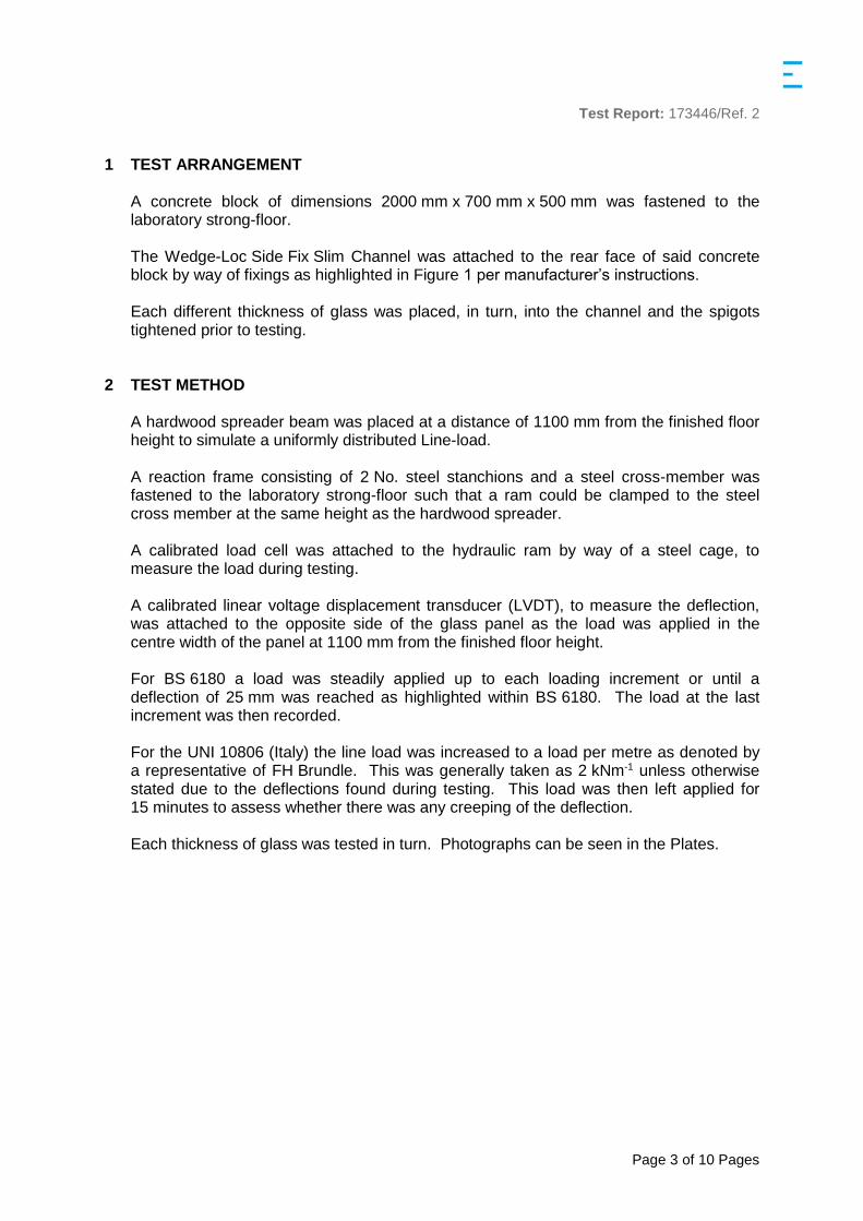
1 TEST ARRANGEMENT A concrete block of dimensions 2000 mm x 700 mm x 500 mm was fastened to the laboratory strong-floor. The Wedge-Loc Side Fix Slim Channel was attached to the rear face of said concrete block by way of fixings as highlighted in Figure 1 per manufacturer’s instructions. Each different thickness of glass was placed, in turn, into the channel and the spigots tightened prior to testing.
2 TEST METHOD A hardwood spreader beam was placed at a distance of 1100 mm from the finished floor height to simulate a uniformly distributed Line-load. A reaction frame consisting of 2 No. steel stanchions and a steel cross-member was fastened to the laboratory strong-floor such that a ram could be clamped to the steel cross member at the same height as the hardwood spreader. A calibrated load cell was attached to the hydraulic ram by way of a steel cage, to measure the load during testing. A calibrated linear voltage displacement transducer (LVDT), to measure the deflection, was attached to the opposite side of the glass panel as the load was applied in the centre width of the panel at 1100 mm from the finished floor height. For BS 6180 a load was steadily applied up to each loading increment or until a deflection of 25 mm was reached as highlighted within BS 6180. The load at the last increment was then recorded. For the UNI 10806 (Italy) the line load was increased to a load per metre as denoted by a representative of FH Brundle. This was generally taken as 2 kNm-1 unless otherwise stated due to the deflections found during testing. This load was then left applied for 15 minutes to assess whether there was any creeping of the deflection. Each thickness of glass was tested in turn. Photographs can be seen in the Plates.

Test Report: 173446/Ref. 2
Page 4 of 10 Pages
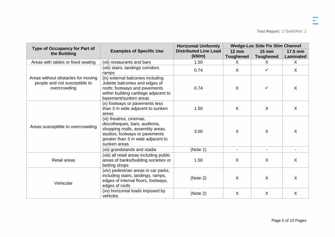
3 RESULTS
Table 1 - BS 6180 Results
Type of Occupancy for Part of the Building
Examples of Specific Use Horizontal Uniformly Distributed Line Load
(kN/m)
Wedge-Loc Side Fix Slim Channel 12 mm
Toughened 15 mm
Toughened 17.5 mm
Laminated
Domestic and residential activities
(i) all areas within or serving exclusively one single family dwelling including stairs, landings, etc. but excluding external balconies and edges of roofs
0.36
(ii) other residential, i.e. houses of multiple occupancy and balconies, including Juliette balconies and edges of roofs in single family dwellings
0.74 X X
Offices and work areas not included elsewhere, including
storage areas
(iii) light access stairs and gangways not more than 600 mm wide
0.22
(iv) light pedestrian traffic routes in industrial and storage buildings except designated escape routes
0.36
(v) areas not susceptible to overcrowding in office and institutional buildings, also industrial and storage buildings except as given above
0.74 X X
Areas where people might congregate
(vi) areas having fixed seating within 530 mm of the barrier, balustrade or parapet
1.50 X X X
Test Report: 173446/Ref. 2
Page 5 of 10 Pages
Type of Occupancy for Part of the Building
Examples of Specific Use Horizontal Uniformly Distributed Line Load
(kN/m)
Wedge-Loc Side Fix Slim Channel 12 mm
Toughened 15 mm
Toughened 17.5 mm
Laminated Areas with tables or fixed seating (vii) restaurants and bars 1.50 X X X
Areas without obstacles for moving people and not susceptible to
overcrowding
(viii) stairs, landings corridors ramps
0.74 X X
(ix) external balconies including Juliette balconies and edges of roofs; footways and pavements within building cartilage adjacent to basement/sunken areas
0.74 X X
Areas susceptible to overcrowding
(x) footways or pavements less than 3 m wide adjacent to sunken areas
1.50 X X X
(xi) theatres, cinemas, discotheques, bars, auditoria, shopping malls, assembly areas, studios; footways or pavements greater than 3 m wide adjacent to sunken areas
3.00 X X X
(xii) grandstands and stadia (Note 1) - - -
Retail areas (xiii) all retail areas including public areas of banks/building societies or betting shops
1.50 X X X
Vehicular
(xiv) pedestrian areas in car parks, including stairs, landings, ramps, edges of internal floors, footways, edges of roofs
(Note 2) X X X
(xv) horizontal loads imposed by vehicles
(Note 2) X X X
Test Report: 173446/Ref. 2
Page 6 of 10 Pages
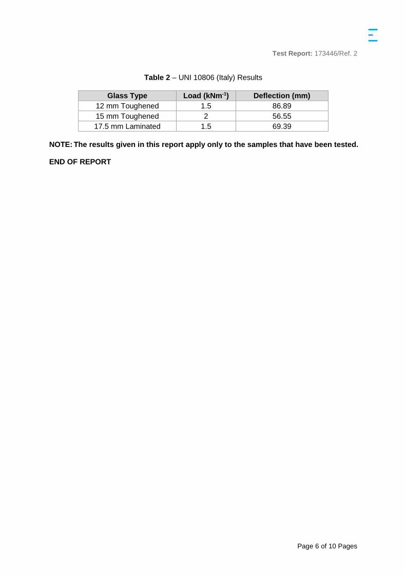
Table 2 – UNI 10806 (Italy) Results
Glass Type Load (kNm-1) Deflection (mm) 12 mm Toughened 1.5 86.89
15 mm Toughened 2 56.55
17.5 mm Laminated 1.5 69.39
NOTE: The results given in this report apply only to the samples that have been tested. END OF REPORT
Test Report: 173446/Ref. 2
Page 7 of 10 Pages
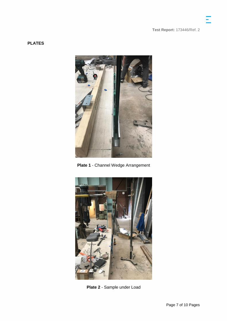
PLATES
Plate 1 - Channel Wedge Arrangement
Plate 2 - Sample under Load
Test Report: 173446/Ref. 2
Page 8 of 10 Pages
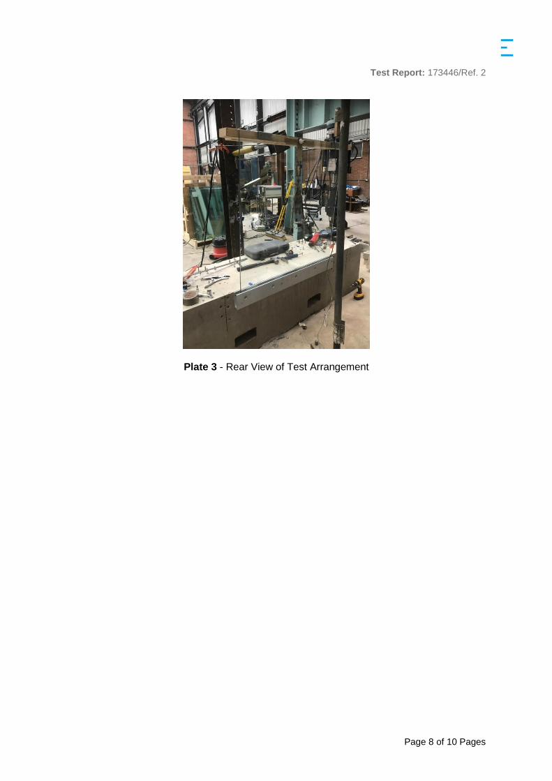
Plate 3 - Rear View of Test Arrangement
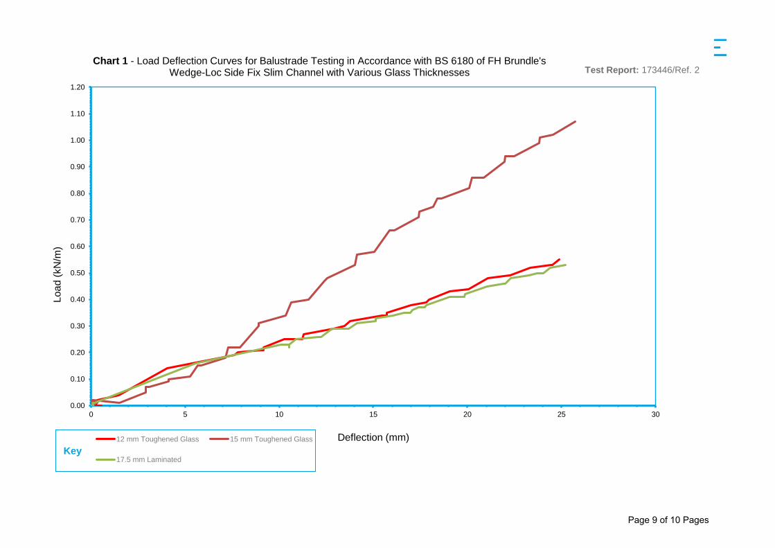
0.00
0.10
0.20
0.30
0.40
0.50
0.60
0.70
0.80
0.90
1.00
1.10
1.20
0 5 10 15 20 25 30
Loa
d (
kN
/m)
Deflection (mm)
Chart 1 - Load Deflection Curves for Balustrade Testing in Accordance with BS 6180 of FH Brundle's Wedge-Loc Side Fix Slim Channel with Various Glass Thicknesses
12 mm Toughened Glass 15 mm Toughened Glass
17.5 mm LaminatedKey
Test Report: 173446/Ref. 2
Page 9 of 10 Pages
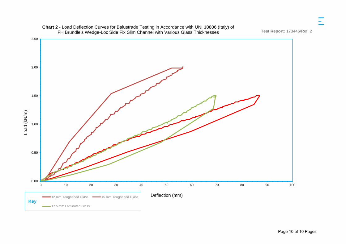
0.00
0.50
1.00
1.50
2.00
2.50
0 10 20 30 40 50 60 70 80 90 100
Loa
d (
kN
/m)
Deflection (mm)
Chart 2 - Load Deflection Curves for Balustrade Testing in Accordance with UNI 10806 (Italy) of FH Brundle's Wedge-Loc Side Fix Slim Channel with Various Glass Thicknesses
12 mm Toughened Glass 15 mm Toughened Glass
17.5 mm Laminated Glass
Key
Test Report: 173446/Ref. 2
Page 10 of 10 Pages
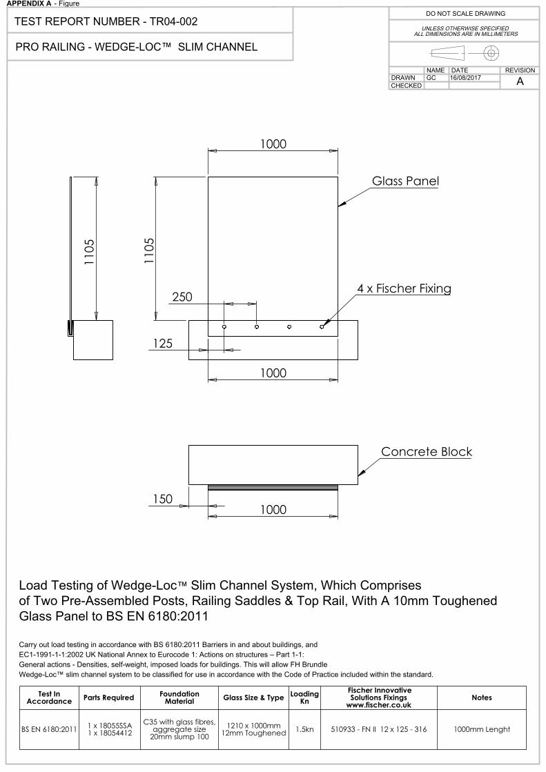
1000
1000
110
5
125
250
Glass Panel
4 x Fischer Fixing
1000 150
Concrete Block
110
5
Load Testing of Wedge-Loc™ Slim Channel System, Which Comprisesof Two Pre-Assembled Posts, Railing Saddles & Top Rail, With A 10mm ToughenedGlass Panel to BS EN 6180:2011
Carry out load testing in accordance with BS 6180:2011 Barriers in and about buildings, andEC1-1991-1-1:2002 UK National Annex to Eurocode 1: Actions on structures – Part 1-1:General actions - Densities, self-weight, imposed loads for buildings. This will allow FH BrundleWedge-Loc™ slim channel system to be classified for use in accordance with the Code of Practice included within the standard.
Test In Accordance Parts Required Foundation
Material Glass Size & Type Loading Kn
Fischer Innovative Solutions Fixings
www.fischer.co.ukNotes
BS EN 6180:2011 1 x 18055SSA 1 x 18054412
C35 with glass fibres, aggregate size
20mm slump 1001210 x 1000mm
12mm Toughened 1.5kn 510933 - FN II 12 x 125 - 316 1000mm Lenght
16/08/2017GCDATENAME
DRAWNREVISION
UNLESS OTHERWISE SPECIFIED ALL DIMENSIONS ARE IN MILLIMETERS
DO NOT SCALE DRAWINGTEST REPORT NUMBER - TR04-002
PRO RAILING - WEDGE-LOC™ SLIM CHANNEL
CHECKED A
APPENDIX A - Figure