Embed Size (px)
Citation preview
srRoJiRENsrci zxuSeeni UsrAV, s. p.(Engineering Test Institute, Pubtic Enterprise)
Hudcova 56b,621 00 Brno, Czech Republic
TEST REPORTNo.39-5188/T
Hot water boiler burning wood
EKo-VIMAR oRLANSKIul. Nyska 17 B48-385 Otmuch6wPOLAND
EKo-VIMAR oRLANSKIul. Nyska 17 B48-385 Otmuch6wPOLAND
Ing. AleS Onderek
2005-11-10
Page 1 of 16
Product:
Customer:
Manufacturer:
Responsible employee:
Report issue date:
Type designation: ORLAN 80
Versions:
Distribution list: 1 copy to the Engineering Test Institute1 copy to the Customer
This report may be copied in its entirety without written consent of the Engineering Test Institute. Partial copiesare subject to approval.
STROJIRENSI(Y ZKUSEBNI USTAV, s. p. Report No. 39-5188/TPage 2 of 16Engineering Test Institute
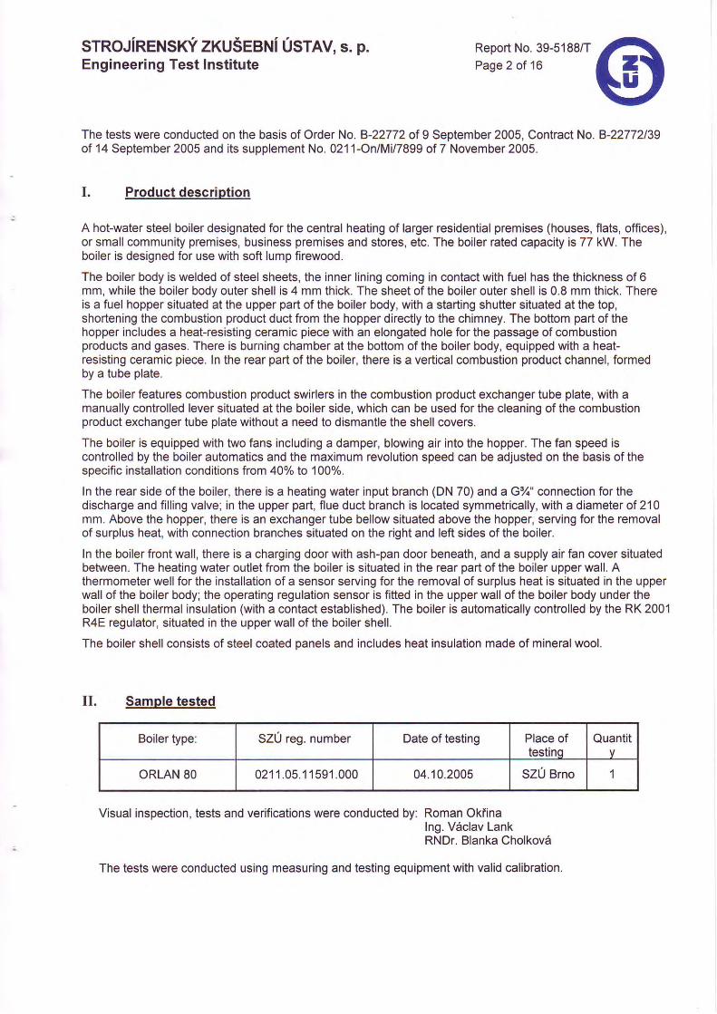
The tests were conducted on the basis of Order No. 8-22772 ol 9 September 2005, Contract No. 8-22772139of 14 September 2005 and its supplement No. 0211-On/Mi/7899 of 7 November 2005.
Product description
A holwater steel boiler designated for the central heating of larger residential premises (houses, flats, offices),or small community premises, business premises and stores, etc. The boiler rated capacity is 77 kW. Theboiler is designed for use with soft lump flrewood.
The boiler body is welded of steel sheets, the inner lining coming in contact with fuel has the thickness of 6mm, while the boiler body outer shell is 4 mm thick. The sheet of the boiler outer shell is 0.8 mm thick. Thereis a fuel hopper situated at the upper part of the boiler body, with a starting shutter situated at the top,shortening the combustion product duct from the hopper directly to the chimney. The bottom part of thehopper includes a heatresisting ceramic piece with an elongated hole for the passage of combustionproducts and gases. There is burning chamber at the bottom of the boiler body, equipped with a heatresisting ceramic piece. ln the rear part of the boiler, there is a vertical combustion product channel, formedby a tube plate.
The boiler features combustion product swirlers in the combustion product exchanger tube plate, with amanually controlled lever situated at the boiler side, which can be used for the cleaning of the combustionproduct exchanger tube plate without a need to dismantle the shell covers.
The boiler is equipped with two fans including a damper, blowing air into the hopper. The fan speed iscontrolled by the boiler automatics and the maximum revolution speed can be adjusted on the basis of thespecific installation conditions from 40% to 100%.
In the rear side of the boiler, there is a heating water input branch (DN 70) and a G%" connection for thedischarge and filling valve; in the upper part, flue duct branch is located symmetrically, with a diameter of 210mm. Above the hopper, there is an exchanger tube bellow situated above the hopper, serving for the removalof surplus heat, with connection branches situated on the right and left sides of the boiler.
In the boiler front wall, there is a charging door with ash-pan door beneath, and a supply air fan cover situatedbetween. The heating water outlet from the boiler is situated in the rear part of the boiler upper wall. Athermometer well for the installation of a sensor serving for the removal of surplus heat is situated in the upperwall of the boiler body; the operating regulation sensor is fitted in the upper wall of the boiler body under theboiler shell thermal insulation (with a contact established). The boiler is automatically controlled by the RK 2001R4E regulator, situated in the upper wall of the boiler shell.
The boiler shell consists of steel coated oanels and includes heat insulation made of mineral wool.
II. Sample tested
Visual inspection, tests and verifications were conducted by: Roman Okiinalng. Vaclav LankRNDr. BIanka Cholkova
The tests were conducted using measuring and testing equipment with valid calibration.
Boiler type: SZ0 reg. number Date of testing Place oftestinq
Quantit
ORLAN 80 021 1 .05.1 1591 .000 04.10.2005 SZU Brno I
srRoJiRENSrci zxuSeeNi Usrav, s. p.Engineering Test Institute
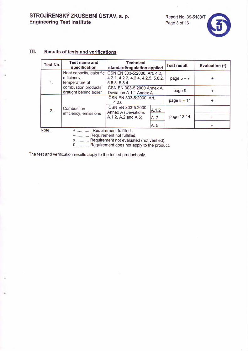
UL Results of tests and verifications
Note:
Report No. 39-5188/TPage 3 of 16
+ . . . . . . . . . . . . . Requirement ful f i l led.- . . . . . . . . . . . Requirement not fu l f i l led.x ........... Requirement not evaluated (not verified).0 ........... Requirement does not apply to the product.
The test and verification results apply to the tested product only.
Test No. Test name andspecification
Technicalstandard/requlation applied
Test result Evaluation (.)
1
Heat capacity, calorificefficiency,temperature ofcombustion products,draught behind boiler
CSN EN 303-5:2000, At1.4.2,4.2.1, 4.2.2, 4.2.4, 4.2.5, 5.8.2,5 .8 .3 ,5 .8 .4
p a g e 5 - 7
CSN EN 303-5:2000 Annex A,Deviation A.1.1 Annex A page 9 +
2. Combustionefficiency, emissions
CSN EN 303-5:2000, Art.4.2.6 page 8 - 11
CSN EN 303-5:2000,Annex A (DeviationsA.1.2, A.2 and A.5)
4 .1 .2page 12-144 . 2
A . C
sTRoJiRENSrci zxuSeaNi Usrlv, s. p.Engineering Test Institute
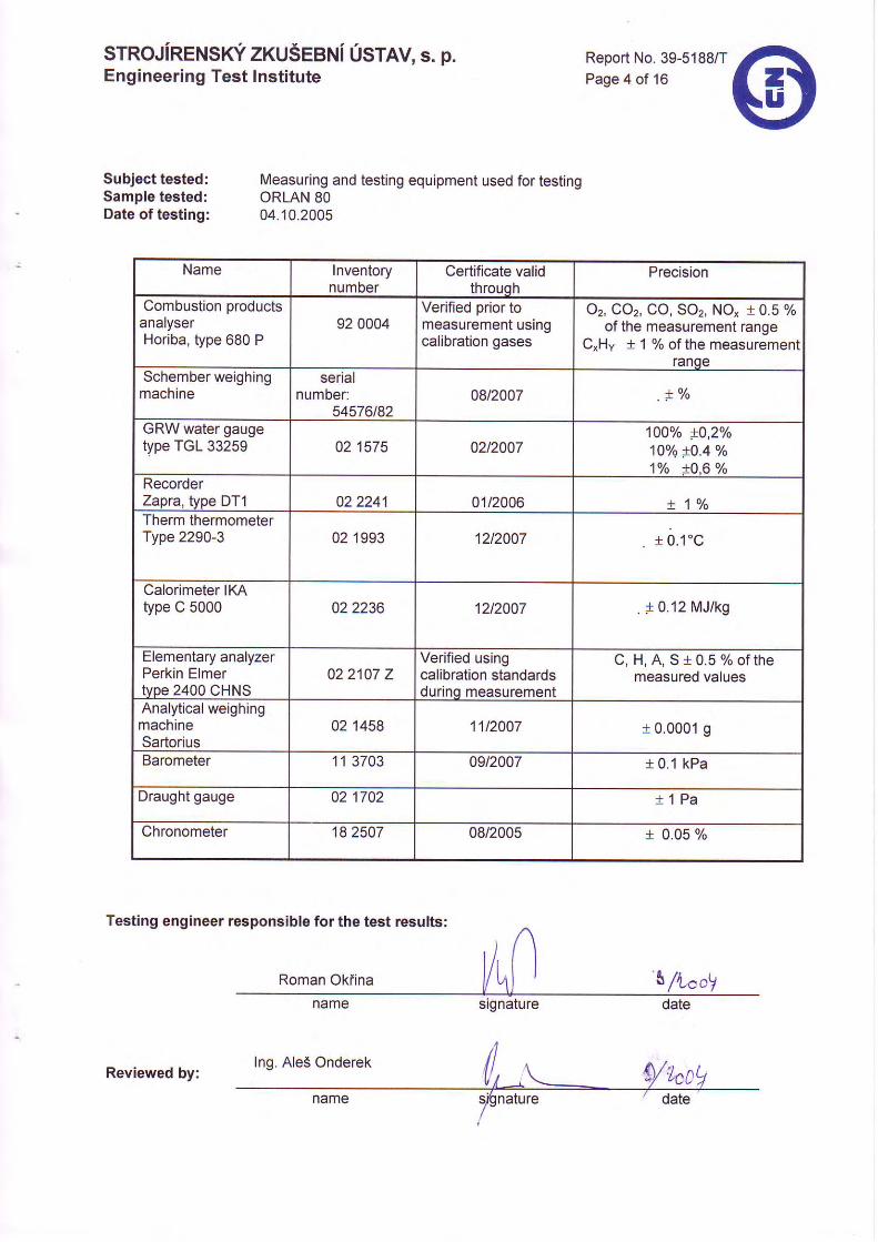
Subject tested:Sample tested:Date of testing:
Measuring and testing equipment used for testingORLAN 8004. '10.2005
Report No. 39-5188/TPage 4 of 16
Name Inventorynumber
Certificate validthrouqh
Precrsion
Combustion productsanalyserHoriba, type 680 P
92 0004Venfied prior tomeasurement ustngcalibration gases
02, cor, co, so2, No, 10.5 %of the measurement range
C"Hy t1%of the measurementranqe
Schember weighingmachine
serialnumber:
54576t8208t2007 . !
o/o
GRW water gaugetype TGL 33259 02 1575 02t2007
100% t0,20/o10% +0.4 vo1Yo !0,6 o/o
RecorderZapra, type DT1 02 2241 01/2006 + 1 %Therm thermometerType 2290-3 02 1993 12t2007 1 0 . 1 ' c
Calorimeter IKAtype C 5000 022236 12t2007 . i 0.12 MJ/kg
Elementary analyzerPerkin Elmertype 2400 CHNS
02 2107 ZVerified usingcalibration standardsdurinq measurement
C , H , A , S 1 0 . 5 % o f t h emeasured values
Analytical weighingmachineSartorius
02 1458 11t2007 I 0.0001 g
Barometer 11 3703 09t2Q07 t 0.1 kPa
Draught gauge 02 1702 ! 1 P a
Chronometer 18 2507 08/2005 t 0.05 %
Testing engineer responsible for the test results:
signature
(,Reviewed by:

STROJIRENSKY ZKUSEBNI USTAV, s. p.Engineering Test Institute
Subject tested:Sample tested:Date of testing:
Tests conducted according to CSN EN 303-5:2000 methodology.
AVERAGE MEASURED AND CALCULATED VALUES:
Analvsis of combustion oroducts:
the boiler capacity amounting tothe boiler capacity amounting to
Report No. 39-5188/TPage 5 of 16
99.5% of the rated capacity.101.3% of the rated capacity.
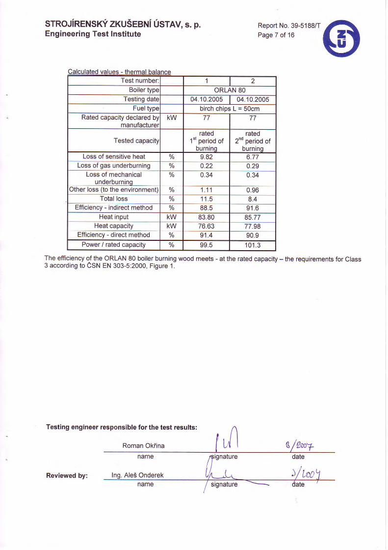
Heat capacity, input, calorific efficiencyORLAN 8004.10.2005
Test number: 1Boiler type ORLAN 80
Testing date 04.10.2005 04.10.2005Fuel type b i r chch ipsL=50cm
Rated capacity declared bymanufacturer
KW 77 77
Tested capacityrated
'1"t period ofDUrnlnq
raled2nd period of
DUrntnqDraft behind boiler Pa 24,6 27 ,0Fuel - unburn kg.h' 19 ,05 19,50Water - input temperalure 58,0 50,3Water - output temperature 68,3Water - cooling temperature 58,0 50,3Water - volume flow rate m".h- 6,355 9,275Air - indoor temperature 25 ,1 25,4Air - relative humidity o/o 65,3 62,7Air - barometric Dressure Torr 736,0 736,0Combustion products -temperature
129,4 110,4
Test number: 1 2Boiler type ORLAN 80
Testing date 04.10.2005 04.10.2005Fuel type b i r chch ipsL=50cm
Rated capacity declared bymanufacturer
KW 77 77
Tested capacityrated
1*t period ofburninq
rated2nd period of
burninqCombustionproducts - analysis:
Oz Vo 8.6 6.8Coz Yo 10 .8 13 .0
Yo 0.036 0.058NO" ppm 79.5 108.5CxHy ppm 336 co
Soz Vo 0.00 0.00Note: a) Test No. 1 was conducted with
b) Test No. 2 was conducted with

sTRoJiRENSrci zxuSeeNi Usrlv, s. p.Engineering Test Institute
Report No. 39-5188/TPage 6 of 16
Test number: 1Boiler type ORLAN 80
Testing date 04.10.2005 04.10.2005Fuel gpe b i r chch ipsL=50cm
Rated capacity declared bymanufacturer
KW 77 77
Tested capacityrated
1"t period ofburninq
rated2nd period of
burninqStoich. oxygen volume m'.kg- 0 . 9 1 9 0 .919
Stoich. air volume m'.kg' 4.375 4.375Stoichiometric volume of dry
combustion Droductsm".kg- 4 . Z O I
Volume of dry combustionDroducts. actual
m-.kg- 7.454 6.187
Combustion air multiple 1 . 6 7 1.46Volume of H2O in the
combustion airm'.kg- 0.103 0.084
Volume of H2O in thecombustion oroducts
m".kg- 0.966 0.947
Max. volume of CO2 % 18.93 18.93Max. volume of SO2 % 0.07 0.00
srRoJiRENsrci zruSeeNi Usrtv, s. p.Engineering Test Institute
Test number: 1
Boiler type ORLAN 80Testing date 04.10.2005 04.10.2005
Fuel type b i r chch ipsL=50cmRated capacity declared by
manufacturerKW 77 77
Tested capacityrated
l"rperiod ofburnino
rated2nd period of
burninqLoss of sensitive heat o/o 9.82 6.77
Loss of gas underburning o/o 0.22 0.29Loss of mechanical
underburninq% 0.34 0.34
Other Ioss (to the environment) % 1 . 1 1 0.96Total loss Yo 1 1 . 5 8.4
Efficiency - indlrect method % 88.5 9 1 . 6Heat input KW 83.80 85.77
Heat capacity KW / o .oJ 77.98Efficiencv - direct method Yo 9't.4 90.9
Power / rated capacity % 99.5 '101 .3
The efficiency ol the ORLAN 80 boiler burning wood meets - at the rated capacity - the requirements for Class3 according to CSN EN 303-5:2000, Figure 1.
Testing engineer responsible for the test results:
L/l LwyRoman Okfina
date
Report No. 39-5188/TPage 7 of 16
name
AleS OnderekReviewed by:signature
)/ t-oo
sTRoJiRENSrci zxuSeeNi osrev, s. p.Engineering Test lnstitute
Report No. 39-5188iTPage 8 of 16
Subject tested:Sample tested:Date of testing:
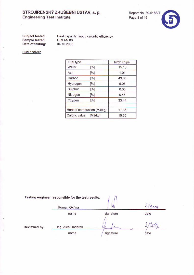
Fuel analvsis
name
Ales Onderek
Heat capacity, input, calorific efficiencyORLAN 8004.10.2005
Testing engineer responsible for the test results:
Roman Okfina
Fuel tvpe birch chiDsWater lY"l 15 .18
Ash lY"l 1 . 0 1
Carbon lv"l 43.83
Hydrogen lY"l 6.08
Sulphur t%l 0.00
Nitrogen t%l 0.45
Oxygen lY"l 33.44
Heat of combustion [MJ/kgl 17.35
Caloric value IMJ/kg] 15.65
Reviewed by:
sTRoJiRENsrci zruSeeNiUsrtv, s. p.Engineering Test lnstitute
Subject tested:Sample tested:Date of testing:
Tests conducted according to CSN EN 303-5:2000 methodology.
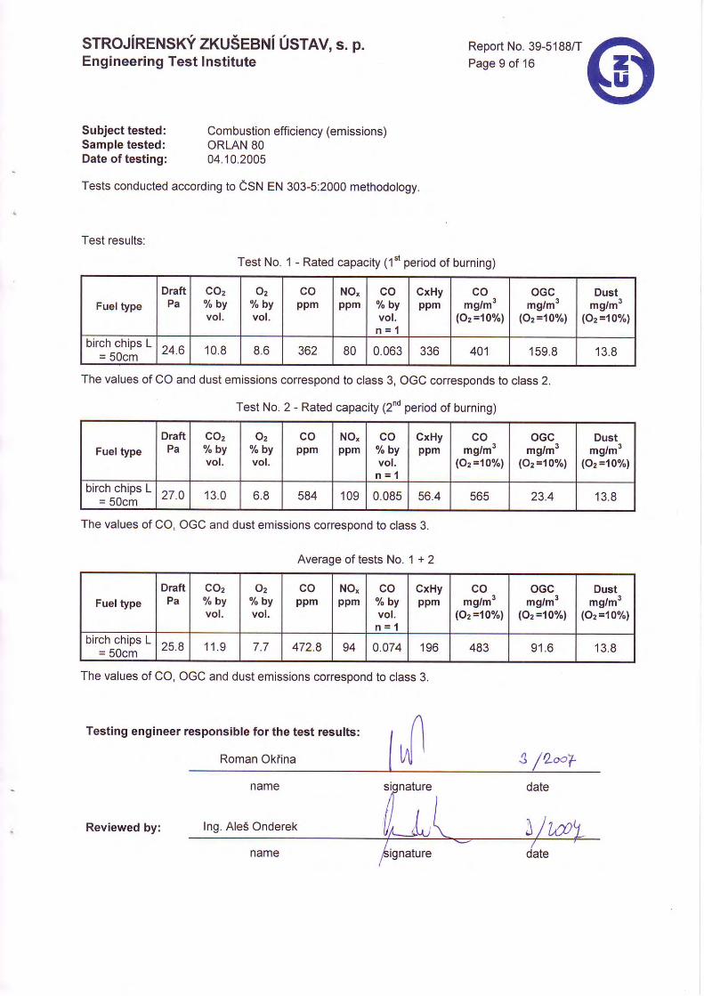
Test results:
Report No. 39-5188/TPage 9 of 16
Combustion efficiency (emissions)ORLAN 8004.10.2005
Test No. 1 - Rated capacity (1"t period of burning)
Fuel typeDraftPa
coz"/, byvol.
Oz% b vvol.
ppmNO,ppm
co% b vvol.
n = l
CxHyppm
comg/m3
(O2='too/ol
oGcmg/m3
(O2=looh,
Dustmg/m3
lOz=10o/.1
birch chips L= 50cm 24.6 10 .8 8.6 362 80 0.063 JJO 401 159.8 13.8
The values of CO and dust emissions correspond to class 3, OGC corresDonds to class 2.
Test No. 2 - Rated capacity (2nd period of burning)
Fuel typeDraftPa
COzo/. byvol.
Oz% b vvol.
coppm
NO,ppm
co% b vvol.n = l
GxHyppm
comg/mr
(oz =107")
oGcmg/m3
(O, =10%)
Dustmg/m3
(o2=10%l
birch chips L= 50cm 27.0 13 .0 6.8 584 109 0.085 56.4 565 23.4 13 .8
The values of CO, OGC and dust emissions corresDond to class 3.
Average of tests No. 1 + 2
FueltypeDraftPa "/" by
vol.
v2% b vvol.
coppm
NO"ppm
co%bvvol.n = 1
CxHyppm
comg/m3
(Oz =10%)
oGcmg/m3
(O2=10olol
Dustmg/mr
(oz ='10"/")
birch chips L= 50cm 25.8 1 1 . 9 472.8 94 0.074 196 483 9 1 . 6 13 .8
The values of CO, OGC and dust emissions corresoond to class 3.
Testing engineer responsible for the test results:
Roman Oklina
Reviewed by:
STROJIRENSKY ZKUSEBNI USTAV, s. p.Engineering Test Institute
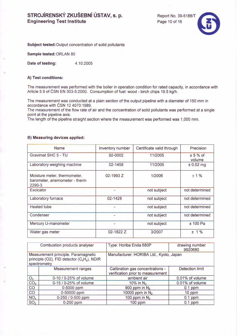
Subject tested:Output concentration of solid pollutants
Sample tested: ORLAN 80
Date of testing: 4.10.2005
Report No. 39-5188/TPage 10 of 16
A) Test conditions:
The measurement was performed with the boiler in operation condition for rated capacity, in accordance withArticle 5.9 of CSN EN 303-5:2000. Consumption of fuel: wood - birch chips 19.5kg/h.
The measurement was conducted at a plain section of the output pipeline with a diameter of 150 mm inaccordance with CSN '12 4070:1989.The measurement of the flow rate of air and the concentration of solid pollutants was performed at a singlepoint at the pipeline axis.The length of the pipeline straight section where the measurement was performed was 1,000 mm.
B) Measuring devices applied:
Name Inventory number Certificate valid through Precision
Grav ima tSHCS-TU 92-0002 11t2005 l 5 % o fvolume
Laboratory weighing machine 02-1458 11t2005 t 0.02 mg
Moisture meter, thermomeler,barometer, anemometer - therm2250-3
02-1993 Z 1t2006 r 1 %
Excicator not subject not determined
Laboratory furnace 02-1428 not subject not determined
Heated tube not subject not determined
Condenser not subject not determined
Mercury U-manometer not subject r 100 Pa
Water gas meter 02-18222 3t2007 ! 1 %
Combustion products analyser Type: Horiba Enda 680P drawing number9920680
Measurement principle. Paramagneticprinciple (O2), FID detector (C*H,), NDIRspectrometrv
Manufacturer: HORIBA Ltd., Kyoto, Japan
Measurement ranoes Calibration gas concentrations -verification Drior to measurement
Detection limit
Oz 0-10 | 0-25Yo of volume ambient air 0.01% of volumeCOa 0-15 I 0-25% of volume 10% in N, 0.01% of volumeco 0-5000 DDm 900 oom in N, 0.1 DomCO 0-50000 ppm 10000 oDm in N, 10 oomNO, 0-250 / 0-500 opm 100 ppm in Nr 0.1 DomSoz 0-200 oom 100 opm 0.1 ppm
STRoJIRENSTr zxuSeeNi UStlV, s. p. Report No. 39-5188/TPage 11 of 16Engineering Test Institute
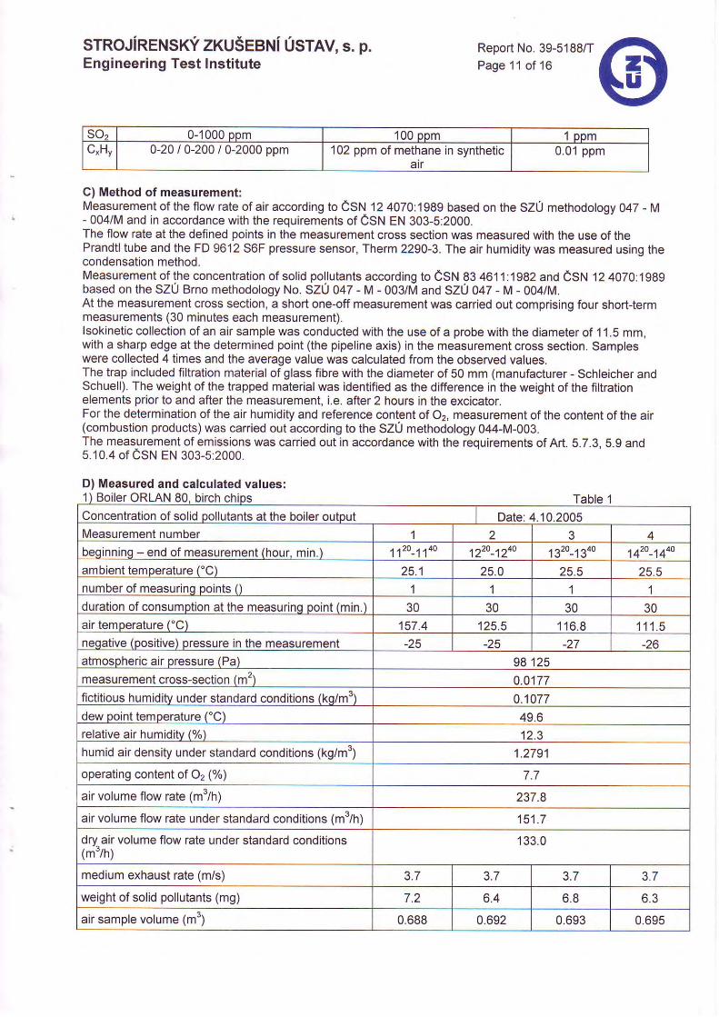
-lJ2 0-1000 Dom 100 ppm 1 oomC"Hv 0-20 / 0-200 / 0-2000 ppm 102 ppm of methane in synthetic
atr0.01 ppm
C) Method of measurement:Measurement of the flow rate of air according to CSN 12 4070:1989 based on the SZU methodology 047 - M- 004/M and in accordance with the requirements of CSN EN 303-5:2000.The flow rate at the defined points in the measurement cross section was measured with the use of thePrandtl tube and the FD 9612 S6F pressure sensor, Therm 2290-3. The air humidity was measured using thecondensation method.Measurement of the concentration of solid pollutants according to CSN 83 461 1:1982 and CSN 12 4070:1989based on the SZU Brno methodology No. SZU 047 - M - 003/M and SZU 042 - M - 004/M.At the measurement cross section, a short one-off measurement was carried out comprising four short{ermmeasurements (30 minutes each measurement).lsokinetic collection of an air sample was conducted with the use of a probe with the diameter of 1 1.5 mm,wlth a sharp edge at the determined point (the pipeline axis) in the measurement cross section. Sampleswere collected 4 times and the average value was calculated from the observed values.The trap included filtration material of glass fibre with the diameter of 50 mm (manufacturer - Schleicher andSchuell). The weight of the trapped material was identified as the difference in the weight of the filtrationelements prior to and after the measurement, i.e. after 2 hours in the excicator.For the determination of the air humidity and reference content of Oz, measurement of the content of the air(combustion products) was carried out according to the SZ0 methodology 044-M-003.The measurement of emissions was carried out in accordance with the requirements of Art. 5.7.3. 5.9 and5.10.4 0f eSN EN 303-5:2000.
D) Measured and calculated values:Boiler ORLAN 80. birch Table 1
Concentration of solid pollutants at the boiler output Date: 4.10.2005Measurement number 4beqinninq - end of measurement (hour. min.) 112o-114o 4 ̂ 2O ^^4O 1B2o-i34o 4 '2O 4 '4O
ambient temperature ('C) 25.1 25.0 25.5 25.5number of measurinq points 0 1 1 1duration of consumption at the measurinq point (min.) 30 30 30 30air temperature ('C) 157 .4 125.5 116 .8 1 1 1 . 5neqative (positive) pressure in the measurement -25 -25 -27 -26atmospheric air pressure (Pa) 98125measurement cross-section (m') 0.0177fictitious humidity under standard conditions (ko/m') 0.1077dew point temperature ('C) 49.6relative air humiditv (%) 12 .3humid air density under standard conditions (kg/m') 1 .2791
operating content of 02 (%) 7.7
air volume flow rate (m3ih) 237.8
air volume flow rate under standard conditions (m"/h) 151.7
dry air volume flow rate under standard conditions 133.0
medium exhaust rate (m/s) 3.7 3.7 3.7 3.7
weight of solid pollutants (mg) 7.2 6.4 6.8 o .J
air sample volume (m3) 0.688 0.692 0.695
srRoJiRENSrci zxuseeNi Usrav, s. p.Engineering Test Institute
Testing engineer responsible for the test results:
name
Ing. AleS OnderekRev iewed by : . . . . . . . . . . . . . . . . . . . . . . . .
name
Report No. 39-5188/TPage 12 of 16
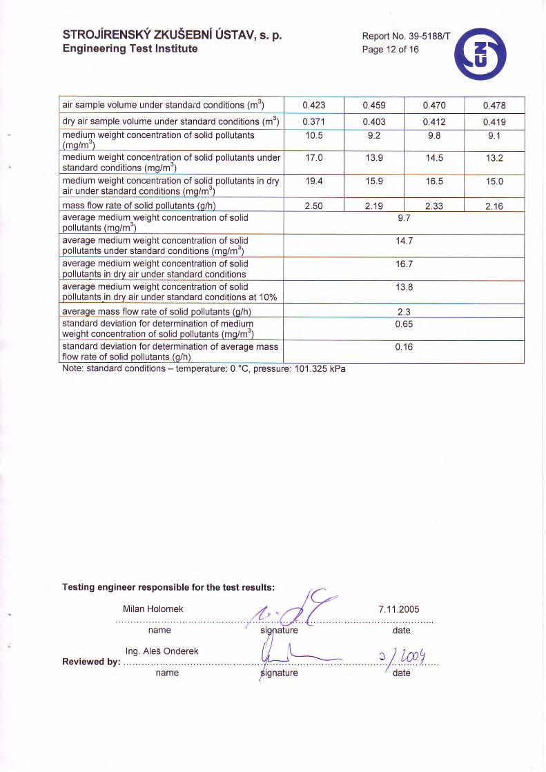
air sample volume under standard conditions (m") 0.423 0.459 0.470 0.478
dry air sample volume under standard conditions (m') 0.371 0.403 0.412 0 . 4 1 9medium weight concentration of solid pollutants(mq/m')
10 .5 9 .8 9 . 1
medium weight concentration of solid pollutants understandard conditions (mg/m")
17 .0 13 .9 14.5 13.2
medium weight concentration of soliq pollutants in dryair under standard conditions (mg/m')
19.4 15 .9 16 .5 15 .0
mass flow rate of solid pollutants (q/h) 2.50 2 . 1 9 2 . 5 5 2 . 1 6average medium-weight concentration of solidpollutants (mg/m')
9.7
average medium weight concentration of solidpollutants under standard conditions (mq/m3)
14.7
average medium weight concentration of solidpollutants in dry air under standard conditions
16.7
average medium weight concentration of solidpollutants in dry air under standard conditions at 10%
13 .8
averaqe mass flow rate of solid pollutants (q/h) z . J
standard deviation for determination of mediumweight concentration of solid pollutants (mg/m3)
0.65
standard deviation for determination of average massflow rate of solid pollutants (q/h)
0 .16
Note: standard conditions - temoerature: 0 "C. oressure: 101 .325 kPa
STRoJiRENstci zxuSeeNi Usrtv, s. p. Report No. 39-5188iTPage 13 of 16Engineering Test Institute
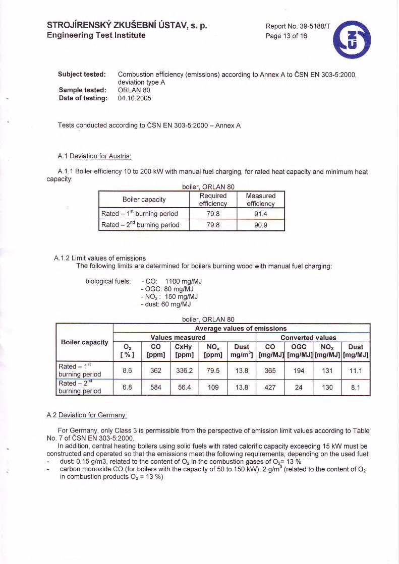
Subject tested: Combustion etficiency (emissions) according to Annex A to CSN EN 303-5:2000,deviation type A
Sample tested: ORLAN 80Date of testing: 04J02005
Tests conducted according to CSN EN 303-5:2000 - Annex A
A.1 Deviation for Austria:
A.1 .1 Boiler efficiency 10 to 200 kW with manual fuel charging, for rated heat capacity and minimum heatcapacrty:
boiler. ORLAN 80
Boiler capacity Requiredefficiencv
Measuredefficiencv
Rated - 1"t burning period 79.8 91 .4
Rated - 2nd burning period 79.8 90.9
A.'1 .2 Limit values of emissionsThe following limits are determined for boilers burning wood with manual fuel charging:
biological fuels: - CO: 1 100 mg/MJ- OGC: 80 mg/MJ- NO": 150 mg/MJ- dust: 60 mo/MJ
ORLAN 80
Boiler capacity
Average values of emissionsValues measured Converted values
o21"/ '1
colppml
CxHylppml
NO"lppml
Dustmg/m31
colms/MJl
oGclmg/MJ:
Noxlms/MJl
Dustlmg/MJl
Rated - '1"'
burning period 8 . 6 502 JJO.Z 13 .8 JOC 194 ' t31 1 1 . 1
Rated - 2""burnino oeriod 6 .8 584 56.4 109 13 .8 427 130 8 . 1
4.2 Deviation for Germanv:
For Germany, only Class 3 is permissible from the perspective of emission limit values according to TableNo. 7 of CSN EN 303-5:2000.
ln addition, central heating boilers using solid fuels with rated calorific capacity exceeding 15 kW must beconstructed and operated so that the emissions meet the following requirements, depending on the used fuel:- dust: 0.1 5 g/m3, related to the content of 02 in the combustion gases of Oa= 13 %- carbon monoxide CO (for boilers with the capacity of 50 to 150 kW): 2 g/m' (related to the content of 02
in combustion products O, = 13 %)
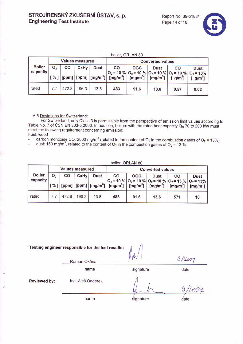
Boilercapacity
Values measured Converted valueso2
l % l
co
[ppml
CxHy
lppml
Dust
Imglm3]
coOz= 10 %Img/m31
oGcOz= 1O o/o
[mg/m3]
DustQz= 10 %[mg/m3]
coOz= 13 %I g/mtl
DustOz' 13loI g/m'l
rated 7.7 472.8 196.3 13 .8 483 91.6 13.6 0.57 0.02
A.5 Deviations for Switzerland._ for Swllgrland, only Class 3 is permissible from the perspective of emission limit values according toTable No. 7 of CSN EN 303-5:2000. In addition, boilers with the rated heat capacity QN 70 to 2OO kW mustmeet the following requirement concerning emlssion:Fuel: wood- carbon monoxide CO: 2000 mg/m3 (related to the content of 02 in the combustion gases of 02 = 13%)- dust: 150 mg/m3, related to thJcontbnt of 02 in the combustion gases of 02 = 13 o;
srRoJiRENSrci zxuSeeNi Usrav, s. p. Report No. 39-5188/TPage 14 of 16Engineering Test Institute
boiler, ORLAN 80
ORLAN 80
Boilercapacity
Values measured Converted valuesO2
t % l
co
lppml
CxHy
lppml
Dust
Img/mr]
coOz= 10 o/o
Imglm31
oGcOz= 'lO ?/o[mg/m31
DustOz= 10 %[mg/m3]
coOz= 13 Yo[mg/m3]
DustOz- 13%Img/m3]
rated 7.7 472.8 196.3 13 .8 483 91.6 13.5 571 1 6
Testing engineer responsible for the test results:
Roman Okfina l*4 q /q ^^--
srgnature
Reviewed by:

STROJIRENSKYZKUSEBNI USTAV, s. p. Report No. 39-5188/TPage 15 of 16Engineering Test Institute
IV. Conclusion
The product - Hofwater boiler burning wood (with manual fuel charging) ORLAN 80 - meets the requirements laiddown in CSN EN 303-5:2000.The requirements of deviations of type A in Annex A to CSN en 303-5:2000 are evaluated for the followingcountries: Austria (AT), Switzerland (CH) and Germany (DE). The above-said requirements regardingdeviations are not fulfilled in OGC of the 1"' burning period for Austria (CSN EN 303-5:2000 A.1.2).
V. List of referenced documents
- Order 8-22772 ot 9 September 2005- Contract 8-22772139 of '14 September 2005, concluded with the customer- Contract Supplement 0211-On/Mi/7899 of 7 November 2005- CSN EN 303-5:2000 - Central heating boilers - Part 5: Central heating boilers burning solid fuels, with
manual or automatic supply and max. rated heating capacity of 300 kW.Terminology, requirements, testing and labelling
- Documentation filed for task No. 37-4009.
The persons stated below are accountable for the accuracy ofthe above-specified data:
'fr i"Ing/ Jiii Evoi6k
Heat and Ecological Equipment Testing StationManager
€ffi

STROJIRENSKY ZKUSEBNI USTAV, s. p.Engineering Test lnstitute
Report No. 39-5188/TPage 16 of 16
Fig. 4: - view of the boiler combustion chamber
Fig. 5: - overall view of the boiler (with acombustion chamber test door andcovered fan)
Fig. 1: - boiler controls
Fig. 2 - overall view of the boiler
Fig. 3: - combustion air fans


![~pubtic of th~ ]~hilippine~ Supreme Court Offi~ of t~e Court …oca.judiciary.gov.ph/wp-content/uploads/2014/05/OCA... · 2014-10-17 · ~pubtic of th~ ]~hilippine~ Supreme Court](https://img.pdfslide.us/doc/110x75/5e552ac0905ef5049a4632b7/pubtic-of-th-hilippine-supreme-court-ofi-of-te-court-oca-2014-10-17.jpg)


![Hudcova 533/78c, 612 00 Brno Czech Republic - · PDF file20 mm Oerlickon [20 x 110] 20 mm Hispano-Suiza [20 x 139] 23 mm NR-23 [23 x 115] 23 mm ZU-23 [23 x 152 B] 23 mm GS [23 x 115]](https://img.pdfslide.us/doc/110x75/5ab3e1b17f8b9a156d8b5ed3/hudcova-53378c-612-00-brno-czech-republic-mm-oerlickon-20-x-110-20-mm-hispano-suiza.jpg)