Embed Size (px)
Citation preview

RFI GlobaPavilion A, ATelephone: +4Facsimile: +4
Manufactu Model No. FCC ID IC Certific Technolog Test Stand
1. This
RFI 2. The 3. This4. The 5. Vers
The BluetooRFI Global respective o
al Services Ashwood Park,
44 (0)1256 31244 (0)1256 3120
Test urer
.
cation No.
gy
dard(s)
s test report sGlobal Servresults in th
s sample testtest results
sion 3.0 supe
oth® word maServices Ltdowners.
Ltd tradingAshwood Way
2000 001
TReport
: A&
: L22
: YO
: 107
: Blu
: FCIndand
shall not be rices Ltd tradis report appted is in comin this reportersedes all p
Date of Iss Checked b
Issued by :
ark and logosd trading as U
g as UL y, Basingstoke
TESTNo. : UR Cambridg
21AY
ONDNW101
792A -DNW
uetooth – Ba
C Parts 15.ustry Canad
d RSS-Gen
reproduced iing as UL.
ply only to thempliance with t are traceabprevious vers
ue:
y:
:
s are ownedUL is under li
, Hampshire, R
T REPL-RPT-Rge Ltd (ARC
020-00
W101020
asic Rate &
109, 15.209da RSS-214.6.3, 4.8,
n full or parti
e sample(s) tthe above sle to the nati
sions.
SWiSE L
pp
Group Q
UL Ve
TT
o
by the Blueticence. Othe
RG23 8BG, UK
PORTRP8926CAM)
EDR
9(a) & 15.240 A8.1(a), A4.9, 4.10 &
ial, without th
tested.tandard(s).ional or inter
28 May 2013
Sarah WilliamLaboratory E
John Neweluality ManagBasingstokeerification Se
This laboratoThe tests repperformed inof accreditat
tooth SIG, Iner trademarks
K
T 65JD17A
47, A8.1(b), A8
& 6.1
he written ap
rnational stan
3
ms Engineer
l ger, WiSE e, ervices
ory is accredported hereinn accordancetion.
nc. and any us and trade n
A V3.0
.1(d), A8.4(
pproval of
ndards.
dited by UKAn have been e with its’ term
use of such mnames are th
2) & A8.5
S.
ms
marks by hose of their

TEST REPORT SERIAL NO: UL-RPT-RP89265JD17A
VERSION NO. 3.0 ISSUE DATE: 28 MAY 2013
Page 2 of 48 RFI Global Services Ltd trading as UL
This page has been left intentionally blank.

TEST REPORT SERIAL NO: UL-RPT-RP89265JD17A
VERSION NO. 3.0 ISSUE DATE: 28 MAY 2013
RFI Global Services Ltd trading as UL Page 3 of 48
Table of Contents 1. Customer Information .................................................................................................................. 4 2. Summary of Testing ..................................................................................................................... 5
2.1. General Information 5 2.2. Summary of Test Results 6 2.3. Methods and Procedures 6 2.4. Deviations from the Test Specification 6
3. Equipment Under Test (EUT) ....................................................................................................... 7 3.1. Identification of Equipment Under Test (EUT) 7 3.2. Description of EUT 7 3.3. Modifications Incorporated in the EUT 7 3.4. Additional Information Related to Testing 8 3.5. Support Equipment 8
4. Operation and Monitoring of the EUT during Testing ............................................................... 9 4.1. Operating Modes 9 4.2. Configuration and Peripherals 9
5. Measurements, Examinations and Derived Results ................................................................ 10 5.1. General Comments 10 5.2. Test Results 11
5.2.1. Receiver/Idle Mode Radiated Spurious Emissions 11 5.2.2. Transmitter 20 dB Bandwidth 15 5.2.3. Transmitter Carrier Frequency Separation 20 5.2.4. Transmitter Number of Hopping Frequencies and Average Time of
Occupancy 23 5.2.5. Transmitter Maximum Peak Output Power 25 5.2.6. Transmitter Radiated Emissions 32 5.2.7. Transmitter Band Edge Radiated Emissions 39
6. Measurement Uncertainty .......................................................................................................... 47 7. Report Revision History ............................................................................................................. 48

TEST REPORT SERIAL NO: UL-RPT-RP89265JD17A
VERSION NO. 3.0 ISSUE DATE: 28 MAY 2013
Page 4 of 48 RFI Global Services Ltd trading as UL
1. Customer Information Company Name: A&R Cambridge Ltd (ARCAM)
Address: Pembroke Avenue, Waterbeach, Cambridgeshire CB25 9QR United Kingdom

TEST REPORT SERIAL NO: UL-RPT-RP89265JD17A
VERSION NO. 3.0 ISSUE DATE: 28 MAY 2013
RFI Global Services Ltd trading as UL Page 5 of 48
2. Summary of Testing
2.1. General Information
Specification Reference: 47CFR15.247
Specification Title: Code of Federal Regulations Volume 47 (Telecommunications) 2012: Part 15 Subpart C (Intentional Radiators) – Section 15.247
Specification Reference: 47CFR15.109
Specification Title: Code of Federal Regulations Volume 47 (Telecommunications) 2012: Part 15 Subpart B (Unintentional Radiators) – Section 15.109
Specification Reference: 47CFR15.209
Specification Title: Code of Federal Regulations Volume 47 (Telecommunications) 2012: Part 15 Subpart C (Intentional Radiators) – Section 15.209
Specification Reference: RSS-Gen Issue 3 December 2010
Specification Title: General Requirements and Information for the Certification of Radio Apparatus
Specification Reference: RSS-210 Issue 8 December 2010
Specification Title: Licence-exempt Radio Apparatus (All Frequency Bands): Category I Equipment.
Site Registration: FCC: 209735; Industry Canada: 3245B-2
Location of Testing: RFI Global Services Ltd trading as UL, Unit 3 Horizon, Wade Road, Kingsland Business Park, Basingstoke, Hampshire, RG24 8AH, United Kingdom
Test Dates: 09 March 2013 to 18 March 2013

TEST REPORT SERIAL NO: UL-RPT-RP89265JD17A
VERSION NO. 3.0 ISSUE DATE: 28 MAY 2013
Page 6 of 48 RFI Global Services Ltd trading as UL
2.2. Summary of Test Results
FCC Reference (47CFR) IC Reference Measurement Result
Part 15.109 RSS-Gen 4.10/6.1 Receiver/Idle Mode Radiated Spurious Emissions
Part 15.247(a)(1) RSS-Gen 4.6.3 RSS-210 A8.1(a) Transmitter 20 dB Bandwidth
Part 15.247(a)(1) RSS-210 A8.1(b) Transmitter Carrier Frequency Separation Part 15.247(a)(1)(iii) RSS-210 A8.1(d) Transmitter Number of Hopping Frequencies
and Average Time of Occupancy
Part 15.247(b)(1) RSS-Gen 4.8 RSS-210 A8.4(2) Transmitter Maximum Peak Output Power
Part 15.247(d)/ 15.209(a)
RSS-Gen 4.9 RSS-210 A8.5 Transmitter Radiated Emissions
Part 15.247(d)/ 15.209(a)
RSS-Gen 4.9 RSS-210 A8.5 Transmitter Band Edge Radiated Emissions
Key to Results
= Complied = Did not comply
2.3. Methods and Procedures
Reference: ANSI C63.4 (2003)
Title: American National Standard for Methods of Measurement of Radio-Noise Emissions from Low-Voltage Electrical and Electronic Equipment in the Range of 9 kHz to 40 GHz
Reference: ANSI C63.10 (2009)
Title: American National Standard for Testing Unlicensed Wireless Devices
2.4. Deviations from the Test Specification
For the measurements contained within this test report, there were no deviations from, additions to, or exclusions from the test specification identified above.

TEST REPORT SERIAL NO: UL-RPT-RP89265JD17A
VERSION NO. 3.0 ISSUE DATE: 28 MAY 2013
RFI Global Services Ltd trading as UL Page 7 of 48
3. Equipment Under Test (EUT)
3.1. Identification of Equipment Under Test (EUT)
Brand Name: Arcam
Model Name or Number: L221AY
Serial Number: Not marked or stated
Hardware Version Number: 1
Software Version Number: 1.0
FCC ID: YONDNW101020-00
Industry Canada Certification Number: 10792A-DNW101020
3.2. Description of EUT
The equipment under test was a Bluetooth module.
3.3. Modifications Incorporated in the EUT
No modifications were applied to the EUT during testing.

TEST REPORT SERIAL NO: UL-RPT-RP89265JD17A
VERSION NO. 3.0 ISSUE DATE: 28 MAY 2013
Page 8 of 48 RFI Global Services Ltd trading as UL
3.4. Additional Information Related to Testing
Tested Technology: Bluetooth
Power Supply Requirement: Nominal 5 VDC
Type of Unit: Transceiver
Channel Spacing: 1 MHz
Mode: Basic Rate Enhanced Data Rate
Modulation: GFSK π/4-DQPSK 8DQPSK
Packet Type: (Maximum Payload) DH5 2DH5 3DH5
Data Rate (Mbit/s): 1 2 3
Maximum Peak Output Power: 8.9 dBm
Transmit Frequency Range: 2402 MHz to 2480 MHz
Transmit Channels Tested: Channel ID Channel Number
Channel Frequency
(MHz)
Bottom 0 2402
Middle 39 2441
Top 78 2480
Receive Frequency Range: 2402 MHz to 2480 MHz
Receive Channels Tested: Channel ID Channel Number
Channel Frequency
(MHz)
Bottom 0 2402
Middle 39 2441
Top 78 2480
3.5. Support Equipment The following support equipment was used to exercise the EUT during testing:
Description: Laptop
Brand Name: Dell
Model Name or Number: Latitude D610
Serial Number: Not marked or stated
Description: Ethernet to SPI conversion PCB
Brand Name: Not marked or stated
Model Name or Number: Not marked or stated
Serial Number: Not marked or stated

TEST REPORT SERIAL NO: UL-RPT-RP89265JD17A
VERSION NO. 3.0 ISSUE DATE: 28 MAY 2013
RFI Global Services Ltd trading as UL Page 9 of 48
4. Operation and Monitoring of the EUT during Testing
4.1. Operating Modes
The EUT was tested in the following operating mode(s):
• Transmit mode with Basic Rate (DH5 packets) or EDR (2DH5 or 3DH5 packets) as required.
• The EUT was in Bluetooth test mode at maximum power for all tests. • Receiver/idle mode.
4.2. Configuration and Peripherals
The EUT was tested in the following configuration(s):
• The EUT was connected to the Ethernet to SPI conversion circuit board, which in turn was connected to a laptop via an Ethernet cable. CSR Bluetest3 application on the laptop PC was used to control the device.

TEST REPORT SERIAL NO: UL-RPT-RP89265JD17A
VERSION NO. 3.0 ISSUE DATE: 28 MAY 2013
Page 10 of 48 RFI Global Services Ltd trading as UL
5. Measurements, Examinations and Derived Results
5.1. General Comments Measurement uncertainties are evaluated in accordance with current best practice. Our reported expanded uncertainties are based on standard uncertainties, which are multiplied by an appropriate coverage factor to provide a statistical confidence level of approximately 95%. Please refer to Section 6. Measurement Uncertainty for details.
In accordance with UKAS requirements all the measurement equipment is on a calibration schedule. All equipment was within the calibration period on the date of testing.

TEST REPORT SERIAL NO: UL-RPT-RP89265JD17A
VERSION NO. 3.0 ISSUE DATE: 28 MAY 2013
RFI Global Services Ltd trading as UL Page 11 of 48
5.2. Test Results
5.2.1. Receiver/Idle Mode Radiated Spurious Emissions Test Summary:
Test Engineer: David Doyle Test Date: 12 March 2013
Test Sample Serial Number: Not marked or stated
FCC Reference: Part 15.109
Industry Canada Reference: RSS-Gen 4.10 / 6.1
Test Method Used: As detailed in ANSI C63.10 Sections 6.3 and 6.5 referencing ANSI C63.4
Frequency Range: 30 MHz to 1000 MHz
Environmental Conditions:
Temperature (°C): 22
Relative Humidity (%): 26
Note(s):
1. The final measured value, for the given emission, in the table below incorporates the calibrated antenna factor and cable loss.
2. All other emissions shown on the pre-scan plot were investigated and found to be ambient or >20 dB below the applicable limit or below the measurement system noise floor.
3. Measurements below 1 GHz were performed in a semi-anechoic chamber (RFI Asset Number K0001) at a distance of 3 metres. The EUT was placed at a height of 80 cm above the reference ground plane in the centre of the chamber turntable. Maximum emission levels were determined by height searching the measurement antenna over the range 1 metre to 4 metres.
Results: Quasi Peak
Frequency (MHz)
Antenna Polarity
Level (dBμV/m)
Limit (dBμV/m)
Margin (dB)
Result
30.909 Vertical 26.4 40.0 13.6 Complied
41.562 Vertical 24.4 40.0 15.6 Complied
41.611 Vertical 24.6 40.0 15.4 Complied
109.453 Vertical 26.7 43.5 16.8 Complied

TEST REPORT SERIAL NO: UL-RPT-RP89265JD17A
VERSION NO. 3.0 ISSUE DATE: 28 MAY 2013
Page 12 of 48 RFI Global Services Ltd trading as UL
Receiver/Idle Mode Radiated Spurious Emissions (continued)
Note: This plot is a pre-scan and for indication purposes only. For final measurements, see accompanying table.
Test Equipment Used: :
RFI No. Instrument Manufacturer Type No. Serial No. Date Calibration Due
Cal. Interval (Months)
K0001 5m RSE Chamber Rainford EMC N/A N/A 24 Oct 2013 12
M1379 Test Receiver Rohde & Schwarz ESIB7 100330 15 Oct 2013 12
A490 Antenna Chase CBL6111A 1590 14 May 2013 12
G0543 Amplifier Sonoma 310N 230801 03 Apr 2013 3
A1834 Attenuator Hewlett Packard 8491B 10444 27 Jan 2014 12
0
5
10
15
20
25
30
35
40
45
50
55
60
65
70
75
80
30M 50M 60M 80M 100M 200M 300M 400M 500M 800M 1G
Leve
l in
dBµV
/m
Frequency in Hz
FCC Part 15.209 Radiated Emissions Class B 30MHz-1GHz 3m
FCC Part 15 Class B Field Strength QP 3M

TEST REPORT SERIAL NO: UL-RPT-RP89265JD17A
VERSION NO. 3.0 ISSUE DATE: 28 MAY 2013
RFI Global Services Ltd trading as UL Page 13 of 48
Receiver/Idle Mode Radiated Spurious Emissions (continued) Test Summary:
Test Engineer: David Doyle Test Date: 12 March 2013
Test Sample Serial Number: Not marked or stated
FCC Reference: Part 15.109
Industry Canada Reference: RSS-Gen 4.10 / 6.1
Test Method Used: As detailed in ANSI C63.10 Sections 6.3 and 6.6 referencing ANSI C63.4
Frequency Range: 1 GHz to 12.5 GHz
Environmental Conditions:
Temperature (°C): 23
Relative Humidity (%): 29
Note(s):
1. The final measured value, for the given emission, in the table below incorporates the calibrated antenna factor and cable loss.
2. Pre-scans above 1 GHz were performed in a fully anechoic chamber (RFI Asset Number K0002) at a distance of 3 metres. The EUT was placed at a height of 1.5 metres above the test chamber floor in the centre of the chamber turntable. All measurement antennas were placed at a fixed height of 1.5 metres above the test chamber floor, in line with the EUT. Final measurements above 1 GHz were performed in a semi-anechoic chamber (RFI Asset Number K0001) at a distance of 3 metres. The EUT was placed at a height of 80 cm above the reference ground plane in the centre of the chamber turntable. Maximum emission levels were determined by height searching the measurement antenna over the range 1 metre to 4 metres.
3. No spurious emissions were detected above the noise floor of the measuring receiver therefore the highest peak noise floor reading of the measuring receiver was recorded as shown in the table below. The peak level was compared to the average limit as opposed to being compared to the peak limit because this is the more onerous limit.
Results:
Frequency (MHz)
Antenna Polarity
Peak Level (dBμV/m)
Average Limit(dBμV/m)
Margin (dB)
Result
3942.307 Horizontal 49.8 54.0 4.2 Complied

TEST REPORT SERIAL NO: UL-RPT-RP89265JD17A
VERSION NO. 3.0 ISSUE DATE: 28 MAY 2013
Page 14 of 48 RFI Global Services Ltd trading as UL
Receiver/Idle Mode Radiated Spurious Emissions (continued)
Test Equipment Used:
RFI No.
Instrument Manufacturer Type No. Serial No. Date Calibration Due
Cal. Interval (Months)
K0002 3m RSE Chamber Rainford EMC N/A N/A 04 Nov 2013 12
M1630 Test Receiver Rohde & Schwarz ESU40 100233 07 Feb 2014 12
A1534 Pre Amplifier Hewlett Packard 8449B 3008A00405 04 Nov 2013 12
A1818 Antenna EMCO 3115 00075692 04 Nov 2013 12
A253 Antenna Flann Microwave 12240-20 128 04 Nov 2013 12
A254 Antenna Flann Microwave 14240-20 139 04 Nov 2013 12
A255 Antenna Flann Microwave 16240-20 519 04 Nov 2013 12
Ref 80 dBµV Att 0 dB*
*
*
1 PKMAXH
A
TDF
3DB
RBW 1 MHz
VBW 3 MHz
SWT 20 ms
AC
Start 1 GHz Stop 4 GHz300 MHz/
-20
-10
0
10
20
30
40
50
60
70
80
1
Marker 1 [T1 ]
46.83 dBµV
3.942307692 GHz
D1 54 dBµV
Date: 12.MAR.2013 09:50:07
Ref 80 dBµV Att 0 dB*
*
*
1 PKMAXH
A
TDF
3DB
RBW 1 MHz
VBW 3 MHz
SWT 20 ms
AC
Start 4 GHz Stop 6 GHz200 MHz/
-20
-10
0
10
20
30
40
50
60
70
80
1
Marker 1 [T1 ]
40.01 dBµV
5.753205128 GHz
D1 54 dBµV
Date: 12.MAR.2013 09:42:14
Ref 80 dBµV Att 0 dB*
*
*
1 PKMAXH
A
TDF
3DB
RBW 1 MHz
VBW 3 MHz
SWT 20 ms
AC
Start 6 GHz Stop 8 GHz200 MHz/
-20
-10
0
10
20
30
40
50
60
70
80
1
Marker 1 [T1 ]
35.84 dBµV
7.868589744 GHz
D1 54 dBµV
Date: 12.MAR.2013 09:36:19
Ref 80 dBµV Att 0 dB*
*
*
1 PKMAXH
A
TDF
3DB
RBW 1 MHz
VBW 3 MHz
SWT 30 ms
AC
Start 8 GHz Stop 12.75 GHz475 MHz/
-20
-10
0
10
20
30
40
50
60
70
80
1
Marker 1 [T1 ]
42.42 dBµV
12.491185897 GHz
D1 54 dBµV
Date: 12.MAR.2013 09:33:40

TEST REPORT SERIAL NO: UL-RPT-RP89265JD17A
VERSION NO. 3.0 ISSUE DATE: 28 MAY 2013
RFI Global Services Ltd trading as UL Page 15 of 48
5.2.2.Transmitter 20 dB Bandwidth Test Summary:
Test Engineer: David Doyle Test Date: 09 March 2013
Test Sample Serial Number: Not marked or stated
FCC Reference: Part 15.247(a)(1)
Industry Canada Reference: RSS-Gen 4.6.3 / RSS-210 A8.1(a)
Test Method Used: As detailed in ANSI C63.10 Section 6.9.1
Environmental Conditions:
Temperature (°C): 24
Relative Humidity (%): 33

TEST REPORT SERIAL NO: UL-RPT-RP89265JD17A
VERSION NO. 3.0 ISSUE DATE: 28 MAY 2013
Page 16 of 48 RFI Global Services Ltd trading as UL
Transmitter 20 dB Bandwidth (continued) Results DH5:
Channel 20 dB Bandwidth (kHz)
Bottom 961.538
Middle 961.538
Top 953.526
Bottom Channel
Middle Channel
Top Channel
Ref 10 dBm Att 10 dB*
*
*
Offset 20.1 dBD1 7.8 dBm
1 PKMAXH
A
LVL
3DB
RBW 30 kHz
VBW 100 kHz
SWT 25 ms
AC
Center 2.402 GHz Span 5 MHz500 kHz/
-90
-80
-70
-60
-50
-40
-30
-20
-10
0
10
1
Marker 1 [T1 ]
-13.37 dBm
2.401527244 GHz
2
Delta 2 [T1 ]
1.04 dB
961.538461533 kHz
D1 7.8 dBm
D2 -12.2 dBm
Date: 8.MAR.2013 12:58:25
Ref 10 dBm Att 10 dB*
*
*
Offset 20.1 dBD1 7.3 dBm
1 PKMAXH
A
LVL
3DB
RBW 30 kHz
VBW 100 kHz
SWT 25 ms
AC
Center 2.441 GHz Span 5 MHz500 kHz/
-90
-80
-70
-60
-50
-40
-30
-20
-10
0
10
1
Marker 1 [T1 ]
-13.81 dBm
2.440527244 GHz
2
Delta 2 [T1 ]
-0.03 dB
961.538461533 kHz
D1 7.3 dBm
D2 -12.7 dBm
Date: 8.MAR.2013 13:00:17
Ref 10 dBm Att 10 dB*
*
*
Offset 20.1 dBD1 6.6 dBm
1 PKMAXH
A
LVL
3DB
RBW 30 kHz
VBW 100 kHz
SWT 25 ms
AC
Center 2.48 GHz Span 5 MHz500 kHz/
-90
-80
-70
-60
-50
-40
-30
-20
-10
0
10
1
Marker 1 [T1 ]
-13.50 dBm
2.479535256 GHz
2
Delta 2 [T1 ]
-0.91 dB
953.525641023 kHz
D1 6.6 dBm
D2 -13.4 dBm
Date: 8.MAR.2013 13:03:33

TEST REPORT SERIAL NO: UL-RPT-RP89265JD17A
VERSION NO. 3.0 ISSUE DATE: 28 MAY 2013
RFI Global Services Ltd trading as UL Page 17 of 48
Transmitter 20 dB Bandwidth (continued) Results 2DH5:
Channel 20 dB Bandwidth (kHz)
Bottom 1282.051
Middle 1266.026
Top 1266.026
Bottom Channel
Middle Channel
Top Channel
Ref 10 dBm Att 10 dB*
*
*
Offset 20.1 dBD1 6 5 dBm
1 PKMAXH
A
LVL
3DB
RBW 30 kHz
VBW 100 kHz
SWT 25 ms
AC
Center 2.402 GHz Span 5 MHz500 kHz/
-90
-80
-70
-60
-50
-40
-30
-20
-10
0
10
1
Marker 1 [T1 ]
-14.26 dBm
2.401366987 GHz
2
Delta 2 [T1 ]
0.65 dB
1.282051282 MHz
D1 6.5 dBm
D2 -13.5 dBm
Date: 8.MAR.2013 13:10:42
Ref 10 dBm Att 10 dB*
*
*
Offset 20.1 dBD1 5 9 dBm
1 PKMAXH
A
LVL
3DB
RBW 30 kHz
VBW 100 kHz
SWT 25 ms
AC
Center 2.441 GHz Span 5 MHz500 kHz/
-90
-80
-70
-60
-50
-40
-30
-20
-10
0
10
1
Marker 1 [T1 ]
-14.45 dBm
2.440358974 GHz
2
Delta 2 [T1 ]
0.22 dB
1.266025641 MHz
D1 5.9 dBm
D2 -14.1 dBm
Date: 8.MAR.2013 13:09:03
Ref 10 dBm Att 10 dB*
*
*
Offset 20.1 dB
1 PKMAXH
A
LVL
3DB
RBW 30 kHz
VBW 100 kHz
SWT 25 ms
AC
Center 2.48 GHz Span 5 MHz500 kHz/
-90
-80
-70
-60
-50
-40
-30
-20
-10
0
10
1
Marker 1 [T1 ]
-15.20 dBm
2.479366987 GHz
2
Delta 2 [T1 ]
0.15 dB
1.266025641 MHz
D1 5.1 dBm
D2 -14.9 dBm
Date: 8.MAR.2013 13:07:09

TEST REPORT SERIAL NO: UL-RPT-RP89265JD17A
VERSION NO. 3.0 ISSUE DATE: 28 MAY 2013
Page 18 of 48 RFI Global Services Ltd trading as UL
Transmitter 20 dB Bandwidth (continued) Results 3DH5:
Channel 20 dB Bandwidth (kHz)
Bottom 1314.103
Middle 1290.064
Top 1290.064
Bottom Channel
Middle Channel
Top Channel
Ref 10 dBm Att 10 dB*
*
*
Offset 20.1 dBD1 6 5 dBm
1 PKMAXH
A
LVL
3DB
RBW 30 kHz
VBW 100 kHz
SWT 25 ms
AC
Center 2.402 GHz Span 5 MHz500 kHz/
-90
-80
-70
-60
-50
-40
-30
-20
-10
0
10
1
Marker 1 [T1 ]
-15.00 dBm
2.401342949 GHz
2
Delta 2 [T1 ]
0.59 dB
1.314102564 MHz
D1 6.5 dBm
D2 -13.5 dBm
Date: 8.MAR.2013 13:12:39
Ref 10 dBm Att 10 dB*
*
*
Offset 20.1 dBD1 5 8 dB
1 PKMAXH
A
LVL
3DB
RBW 30 kHz
VBW 100 kHz
SWT 25 ms
AC
Center 2.441 GHz Span 5 MHz500 kHz/
-90
-80
-70
-60
-50
-40
-30
-20
-10
0
10
1
Marker 1 [T1 ]
-14.86 dBm
2.440342949 GHz
2
Delta 2 [T1 ]
0.62 dB
1.290064103 MHz
D1 5.8 dBm
D2 -14.2 dBm
Date: 8.MAR.2013 13:15:00
Ref 10 dBm Att 10 dB*
*
*
Offset 20.1 dB
1 PKMAXH
A
LVL
3DB
RBW 30 kHz
VBW 100 kHz
SWT 25 ms
AC
Center 2.48 GHz Span 5 MHz500 kHz/
-90
-80
-70
-60
-50
-40
-30
-20
-10
0
10
1
Marker 1 [T1 ]
-16.13 dBm
2.479342949 GHz
2
Delta 2 [T1 ]
1.16 dB
1.290064103 MHz
D1 5.1 dBm
D2 -14.9 dBm
Date: 8.MAR.2013 13:16:42

TEST REPORT SERIAL NO: UL-RPT-RP89265JD17A
VERSION NO. 3.0 ISSUE DATE: 28 MAY 2013
RFI Global Services Ltd trading as UL Page 19 of 48
Transmitter 20 dB Bandwidth (continued) Test Equipment Used:
RFI No.
Instrument Manufacturer Type No. Serial No. Date Calibration Due
Cal. Interval (Months)
M1630 Test Receiver Rohde & Schwarz ESU40 100233 07 Feb 2014 12
A2143 Attenuator Atlan TecRF AN18-20 081120-23 25 May 2013 12
TEST REPORT SERIAL NO: UL-RPT-RP89265JD17A
VERSION NO. 3.0 ISSUE DATE: 28 MAY 2013
Page 20 of 48 RFI Global Services Ltd trading as UL
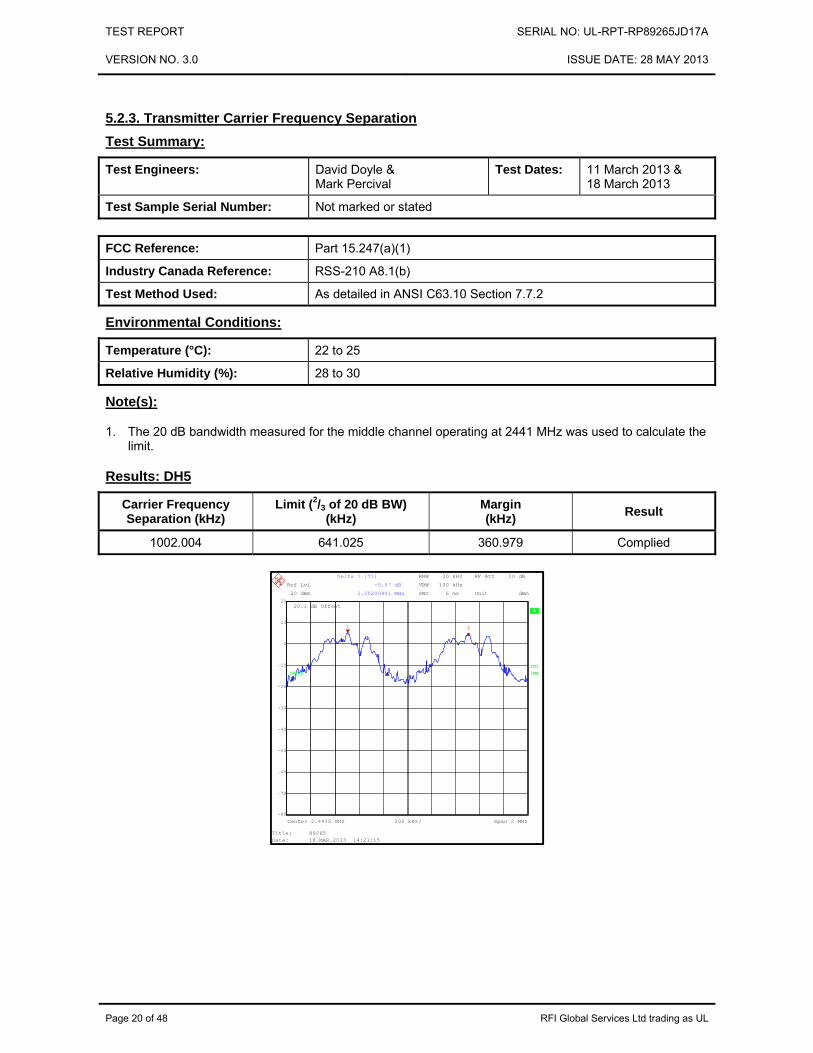
5.2.3. Transmitter Carrier Frequency Separation Test Summary:
Test Engineers: David Doyle & Mark Percival
Test Dates: 11 March 2013 & 18 March 2013
Test Sample Serial Number: Not marked or stated
FCC Reference: Part 15.247(a)(1)
Industry Canada Reference: RSS-210 A8.1(b)
Test Method Used: As detailed in ANSI C63.10 Section 7.7.2
Environmental Conditions:
Temperature (°C): 22 to 25
Relative Humidity (%): 28 to 30
Note(s):
1. The 20 dB bandwidth measured for the middle channel operating at 2441 MHz was used to calculate the limit.
Results: DH5
Carrier Frequency Separation (kHz)
Limit (2/3 of 20 dB BW) (kHz)
Margin (kHz) Result
1002.004 641.025 360.979 Complied
A 20.1 dB Offset
Unit dBm
RBW 30 kHz
VBW 100 kHz
SWT 6 ms
IN1
Center 2.4415 GHz Span 2 MHz200 kHz/
Ref Lvl
20 dBm
Ref Lvl
20 dBm
RF Att 20 dB
1VIEW 1MA
-70
-60
-50
-40
-30
-20
-10
0
10
-80
20
1 1
Delta 1 [T1]
-0.07 dB
1.00200401 MHz
Title: 89265Date: 18.MAR.2013 14:21:15

TEST REPORT SERIAL NO: UL-RPT-RP89265JD17A
VERSION NO. 3.0 ISSUE DATE: 28 MAY 2013
RFI Global Services Ltd trading as UL Page 21 of 48
Transmitter Carrier Frequency Separation (continued) Note(s):
1. The 20 dB bandwidth measured for the middle channel operating at 2441 MHz was used to calculate the limit.
Results: 2DH5
Carrier Frequency Separation (kHz)
Limit (2/3 of 20 dB BW) (kHz)
Margin (kHz) Result
1003.205 844.017 159.188 Complied
Ref 20 dBm Att 20 dB*
*
*
Offset 20.1 dB
1 PKVIEW
2 PKVIEW
A
LVL
3DB
RBW 30 kHz
VBW 100 kHz
SWT 10 ms
AC
Center 2.4415 GHz Span 2 MHz200 kHz/
-80
-70
-60
-50
-40
-30
-20
-10
0
10
20
1
Marker 1 [T1 ]
5.96 dBm
2.441000000 GHz
2
Delta 2 [T2 ]
-0.02 dB
1.003205128 MHz
Date: 11.MAR.2013 09:21:37

TEST REPORT SERIAL NO: UL-RPT-RP89265JD17A
VERSION NO. 3.0 ISSUE DATE: 28 MAY 2013
Page 22 of 48 RFI Global Services Ltd trading as UL
Transmitter Carrier Frequency Separation (continued) Note(s):
1. The 20 dB bandwidth measured for the middle channel operating at 2441 MHz was used to calculate the limit.
Results: 3DH5
Carrier Frequency Separation (kHz)
Limit (2/3 of 20 dB BW) (kHz)
Margin (kHz) Result
1003.205 860.043 143.162 Complied
Test Equipment Used:
RFI No.
Instrument Manufacturer Type No. Serial No. Date Calibration Due
Cal. Interval (Months)
M1630 Test Receiver Rohde & Schwarz ESU40 100233 07 Feb 2014 12
A2143 Attenuator Atlan TecRF AN18-20 081120-23 25 May 2013 12
Ref 20 dBm Att 20 dB*
*
*
Offset 20.1 dB
1 PKVIEW
2 PKVIEW
A
LVL
3DB
RBW 30 kHz
VBW 100 kHz
SWT 10 ms
AC
Center 2.4415 GHz Span 2 MHz200 kHz/
-80
-70
-60
-50
-40
-30
-20
-10
0
10
20
1
Marker 1 [T1 ]
5.94 dBm
2.441000000 GHz
2
Delta 2 [T2 ]
-0.03 dB
1.003205128 MHz
Date: 11.MAR.2013 09:23:23

TEST REPORT SERIAL NO: UL-RPT-RP89265JD17A
VERSION NO. 3.0 ISSUE DATE: 28 MAY 2013
RFI Global Services Ltd trading as UL Page 23 of 48
5.2.4. Transmitter Number of Hopping Frequencies and Average Time of Occupancy Test Summary:
Test Engineer: David Doyle Test Date: 12 March 2013
Test Sample Serial Number: Not marked or stated
FCC Reference: Part 15.247(a)(1)(iii)
Industry Canada Reference: RSS-210 A8.1(d)
Test Method Used: As detailed in ANSI C63.10 Section 7.7.3 & 7.7.4
Environmental Conditions:
Temperature (°C): 23
Relative Humidity (%): 29
Note(s):
1. Tests were performed to identify the average time of occupancy in number of channels (79) x 0.4 seconds. The calculated period is 31.6 seconds.
Results:
Emission Width (μs)
Number of Hops in 31.6
Seconds
Average Time of Occupancy
(s) Limit
(s) Margin
(s) Result
2900.641 108 0.313 0.4 0.087 Complied

TEST REPORT SERIAL NO: UL-RPT-RP89265JD17A
VERSION NO. 3.0 ISSUE DATE: 28 MAY 2013
Page 24 of 48 RFI Global Services Ltd trading as UL
Transmitter Number of Hopping Frequencies and Average Time of Occupancy (continued)
Test Equipment Used:
RFI No.
Instrument Manufacturer Type No. Serial No. Date Calibration Due
Cal. Interval (Months)
M1630 Test Receiver Rohde & Schwarz ESU40 100233 07 Feb 2014 12
A2143 Attenuator Atlan TecRF AN18-20 081120-23 25 May 2013 12
Ref 20 dBm Att 20 dB*
*
*
Offset 20.1 dB
1 PKMAXH
A
LVL
3DB
RBW 100 kHz
VBW 300 kHz
SWT 10 ms
AC
Start 2.4 GHz Stop 2.4835 GHz8.35 MHz/
-80
-70
-60
-50
-40
-30
-20
-10
0
10
20
Date: 12.MAR.2013 12:38:08
Ref 20 dBm Att 25 dB
*
*
Offset 20.1 dB
Center 2.441 GHz 500 µs/
1 PKCLRWR
A SGL
TRGLVL
3DB
RBW 1 MHz
VBW 3 MHz
SWT 5 ms
AC
-80
-70
-60
-50
-40
-30
-20
-10
0
10
20
1
Marker 1 [T1 ]
7.52 dBm
-6.410256 µs
2
Delta 2 [T1 ]
0.69 dB
2.900641 ms
TRG -10.7 dBm
Date: 12.MAR.2013 12:53:20
Ref 20 dBm Att 25 dB
*
*
Offset 20.1 dB
Center 2.441 GHz 3.2 s/
1 PKVIEW
A
LVL
3DB
RBW 100 kHz
VBW 300 kHz
SWT 32 s
AC
-80
-70
-60
-50
-40
-30
-20
-10
0
10
20
Date: 12.MAR.2013 12:56:49

TEST REPORT SERIAL NO: UL-RPT-RP89265JD17A
VERSION NO. 3.0 ISSUE DATE: 28 MAY 2013
RFI Global Services Ltd trading as UL Page 25 of 48
5.2.5. Transmitter Maximum Peak Output Power Test Summary:
Test Engineer: David Doyle Test Date: 09 March 2013
Test Sample Serial Number: Not marked or stated
FCC Reference: Part 15.247(b)(1)
Industry Canada Reference: RSS-Gen 4.8 / RSS-210 A8.4(2)
Test Method Used: As detailed in ANSI C63.10 Section 6.10.1
Environmental Conditions:
Temperature (°C): 24
Relative Humidity (%): 33

TEST REPORT SERIAL NO: UL-RPT-RP89265JD17A
VERSION NO. 3.0 ISSUE DATE: 28 MAY 2013
Page 26 of 48 RFI Global Services Ltd trading as UL
Transmitter Maximum Peak Output Power (continued) Results: DH5
Channel Conducted Peak Power
(dBm)
Conducted Peak Power Limit
(dBm) Margin
(dB) Result
Bottom 8.9 30.0 21.1 Complied
Middle 8.3 30.0 21.7 Complied
Top 7.6 30.0 22.4 Complied
Channel Conducted Peak Power
(dBm)
Declared Antenna Gain
(dBi) EIRP (dBm)
De Facto EIRP Limit
(dBm) Margin
(dB) Result
Bottom 8.9 2.0 10.9 36.0 25.1 Complied
Middle 8.3 2.0 10.3 36.0 25.7 Complied
Top 7.6 2.0 9.6 36.0 26.4 Complied

TEST REPORT SERIAL NO: UL-RPT-RP89265JD17A
VERSION NO. 3.0 ISSUE DATE: 28 MAY 2013
RFI Global Services Ltd trading as UL Page 27 of 48
Transmitter Maximum Peak Output Power (continued) Results: DH5
Bottom Channel
Middle Channel
Top Channel
Ref 10 dBm Att 10 dB*
*
*
Offset 20.1 dB
1 PKMAXH
A
LVL
3DB
RBW 2 MHz
VBW 10 MHz
SWT 2.5 ms
AC
Center 2.402 GHz Span 7 MHz700 kHz/
-90
-80
-70
-60
-50
-40
-30
-20
-10
0
10
1
Marker 1 [T1 ]
8.93 dBm
2.401876603 GHz
Date: 8.MAR.2013 12:38:03
Ref 10 dBm Att 10 dB*
*
*
Offset 20.1 dB
1 PKMAXH
A
LVL
3DB
RBW 2 MHz
VBW 10 MHz
SWT 2.5 ms
AC
Center 2.441 GHz Span 7 MHz700 kHz/
-90
-80
-70
-60
-50
-40
-30
-20
-10
0
10
1
Marker 1 [T1 ]
8.25 dBm
2.440943910 GHz
Date: 8.MAR.2013 12:41:18
Ref 10 dBm Att 10 dB*
*
*
Offset 20.1 dB
1 PKMAXH
A
LVL
3DB
RBW 2 MHz
VBW 10 MHz
SWT 2.5 ms
AC
Center 2.48 GHz Span 7 MHz700 kHz/
-90
-80
-70
-60
-50
-40
-30
-20
-10
0
101
Marker 1 [T1 ]
7.57 dBm
2.479899038 GHz
Date: 8.MAR.2013 12:42:01

TEST REPORT SERIAL NO: UL-RPT-RP89265JD17A
VERSION NO. 3.0 ISSUE DATE: 28 MAY 2013
Page 28 of 48 RFI Global Services Ltd trading as UL
Transmitter Maximum Peak Output Power (continued) Results: 2DH5
Channel Conducted Peak Power
(dBm)
Conducted Peak Power Limit
(dBm) Margin
(dB) Result
Bottom 7.7 21.0 13.3 Complied
Middle 6.8 21.0 14.2 Complied
Top 6.6 21.0 14.4 Complied
Channel Conducted Peak Power
(dBm)
Declared Antenna Gain
(dBi) EIRP (dBm)
De Facto EIRP Limit
(dBm) Margin
(dB) Result
Bottom 7.7 2.0 9.7 27.0 17.3 Complied
Middle 6.8 2.0 8.8 27.0 18.2 Complied
Top 6.6 2.0 8.6 27.0 18.4 Complied

TEST REPORT SERIAL NO: UL-RPT-RP89265JD17A
VERSION NO. 3.0 ISSUE DATE: 28 MAY 2013
RFI Global Services Ltd trading as UL Page 29 of 48
Transmitter Maximum Peak Output Power (continued) Results: 2DH5
Bottom Channel
Middle Channel
Top Channel
Ref 10 dBm Att 10 dB*
*
*
Offset 20.1 dB
1 PKMAXH
A
LVL
3DB
RBW 2 MHz
VBW 10 MHz
SWT 2.5 ms
AC
Center 2.402 GHz Span 7 MHz700 kHz/
-90
-80
-70
-60
-50
-40
-30
-20
-10
0
101
Marker 1 [T1 ]
7.65 dBm
2.402022436 GHz
Date: 8.MAR.2013 12:44:55
Ref 10 dBm Att 10 dB*
*
*
Offset 20.1 dB
1 PKMAXH
A
LVL
3DB
RBW 2 MHz
VBW 10 MHz
SWT 2.5 ms
AC
Center 2.441 GHz Span 7 MHz700 kHz/
-90
-80
-70
-60
-50
-40
-30
-20
-10
0
101
Marker 1 [T1 ]
6.75 dBm
2.440674679 GHz
Date: 8.MAR.2013 12:44:06
Ref 10 dBm Att 10 dB*
*
*
Offset 20.1 dB
1 PKMAXH
A
LVL
3DB
RBW 2 MHz
VBW 10 MHz
SWT 2.5 ms
AC
Center 2.48 GHz Span 7 MHz700 kHz/
-90
-80
-70
-60
-50
-40
-30
-20
-10
0
101
Marker 1 [T1 ]
6.58 dBm
2.479652244 GHz
Date: 8.MAR.2013 12:43:24

TEST REPORT SERIAL NO: UL-RPT-RP89265JD17A
VERSION NO. 3.0 ISSUE DATE: 28 MAY 2013
Page 30 of 48 RFI Global Services Ltd trading as UL
Transmitter Maximum Peak Output Power (continued) Results: 3DH5
Channel Conducted Peak Power
(dBm)
Conducted Peak Power Limit
(dBm) Margin
(dB) Result
Bottom 8.0 21.0 13.0 Complied
Middle 7.2 21.0 13.8 Complied
Top 6.2 21.0 14.8 Complied
Channel Conducted Peak Power
(dBm)
Declared Antenna Gain
(dBi) EIRP (dBm)
De Facto EIRP Limit
(dBm) Margin
(dB) Result
Bottom 8.0 2.0 10.0 27.0 17.0 Complied
Middle 7.2 2.0 9.2 27.0 17.8 Complied
Top 6.2 2.0 8.2 27.0 18.8 Complied

TEST REPORT SERIAL NO: UL-RPT-RP89265JD17A
VERSION NO. 3.0 ISSUE DATE: 28 MAY 2013
RFI Global Services Ltd trading as UL Page 31 of 48
Transmitter Maximum Peak Output Power (continued) Results: 3DH5
Bottom Channel
Middle Channel
Top Channel
Test Equipment Used:
RFI No.
Instrument Manufacturer Type No. Serial No. Date Calibration Due
Cal. Interval (Months)
M1630 Test Receiver Rohde & Schwarz ESU40 100233 07 Feb 2014 12
A2143 Attenuator Atlan TecRF AN18-20 081120-23 25 May 2013 12
Ref 10 dBm Att 10 dB*
*
*
Offset 20.1 dB
1 PKMAXH
A
LVL
3DB
RBW 2 MHz
VBW 10 MHz
SWT 2.5 ms
AC
Center 2.402 GHz Span 7 MHz700 kHz/
-90
-80
-70
-60
-50
-40
-30
-20
-10
0
10
1
Marker 1 [T1 ]
7.97 dBm
2.402100962 GHz
Date: 8.MAR.2013 12:46:04
Ref 10 dBm Att 10 dB*
*
*
Offset 20.1 dB
1 PKMAXH
A
LVL
3DB
RBW 2 MHz
VBW 10 MHz
SWT 2.5 ms
AC
Center 2.441 GHz Span 7 MHz700 kHz/
-90
-80
-70
-60
-50
-40
-30
-20
-10
0
101
Marker 1 [T1 ]
7.24 dBm
2.440966346 GHz
Date: 8.MAR.2013 12:46:59
Ref 10 dBm Att 10 dB*
*
*
Offset 20.1 dB
1 PKMAXH
A
LVL
3DB
RBW 2 MHz
VBW 10 MHz
SWT 2.5 ms
AC
Center 2.48 GHz Span 7 MHz700 kHz/
-90
-80
-70
-60
-50
-40
-30
-20
-10
0
101
Marker 1 [T1 ]
6.24 dBm
2.480112179 GHz
Date: 8.MAR.2013 12:48:08

TEST REPORT SERIAL NO: UL-RPT-RP89265JD17A
VERSION NO. 3.0 ISSUE DATE: 28 MAY 2013
Page 32 of 48 RFI Global Services Ltd trading as UL
5.2.6. Transmitter Radiated Emissions Test Summary:
Test Engineer: David Doyle Test Date: 12 March 2013
Test Sample Serial Number: Not marked or stated
FCC Reference: Parts 15.247(d) & 15.209(a)
Industry Canada Reference: RSS-Gen 4.9 / RSS-210 A8.5
Test Method Used: As detailed in ANSI C63.10 Sections 6.3 and 6.5 referencing ANSI C63.4
Frequency Range 30 MHz to 1000 MHz
Environmental Conditions:
Temperature (°C): 22
Relative Humidity (%): 26
Note(s):
1. The final measured value, for the given emission, in the table below incorporates the calibrated antenna factor and cable loss.
2. The preliminary scans showed similar emission levels below 1 GHz, for each channel of operation. Therefore final radiated emissions measurements were performed with the EUT set to the top channel only.
3. All other emissions shown on the pre-scan plot were investigated and found to be ambient or >20 dB below the applicable limit or below the measurement system noise floor.
4. Measurements below 1 GHz were performed in a semi-anechoic chamber (RFI Asset Number K0001) at a distance of 3 metres. The EUT was placed at a height of 80 cm above the reference ground plane in the centre of the chamber turntable. Maximum emission levels were determined by height searching the measurement antenna over the range 1 metre to 4 metres.
Results: Quasi-Peak / DH5
Frequency (MHz)
Antenna Polarity
Level (dBμV/m)
Limit (dBμV/m)
Margin (dB)
Result
109.453 Vertical 22.5 43.5 21.0 Complied

TEST REPORT SERIAL NO: UL-RPT-RP89265JD17A
VERSION NO. 3.0 ISSUE DATE: 28 MAY 2013
RFI Global Services Ltd trading as UL Page 33 of 48
Transmitter Radiated Emissions (continued)
Note: This plot is a pre-scan and for indication purposes only. For final measurements, see accompanying table.
Test Equipment Used:
RFI No. Instrument Manufacturer Type No. Serial No. Date Calibration Due
Cal. Interval (Months)
K0001 5m RSE Chamber Rainford EMC N/A N/A 24 Oct 2013 12
M1379 Test Receiver Rohde & Schwarz ESIB7 100330 15 Oct 2013 12
A490 Antenna Chase CBL6111A 1590 14 May 2013 12
G0543 Amplifier Sonoma 310N 230801 03 Apr 2013 3
A1834 Attenuator Hewlett Packard 8491B 10444 27 Jan 2014 12
0
5
10
15
20
25
30
35
40
45
50
55
60
65
70
75
80
30M 50M 60M 80M 100M 200M 300M 400M 500M 800M 1G
Leve
l in
dBµV
/m
Frequency in Hz
FCC Part 15.209 Radiated Emissions Class B 30MHz-1GHz 3m
FCC Part 15 Class B Field Strength QP 3M

TEST REPORT SERIAL NO: UL-RPT-RP89265JD17A
VERSION NO. 3.0 ISSUE DATE: 28 MAY 2013
Page 34 of 48 RFI Global Services Ltd trading as UL
Transmitter Radiated Emissions (continued) Test Summary:
Test Engineer: David Doyle Test Date: 11 March 2013
Test Sample Serial Number: Not marked or stated
FCC Reference: Parts 15.247(d) & 15.209(a)
Industry Canada Reference: RSS-Gen 4.9 / RSS-210 A8.5
Test Method Used: As detailed in ANSI C63.10 Sections 6.3 and 6.6 referencing ANSI C63.4
Frequency Range 1 GHz to 25 GHz
Environmental Conditions:
Temperature (°C): 22
Relative Humidity (%): 30
Note(s):
1. The final measured value, for the given emission, in the table below incorporates the calibrated antenna factor and cable loss.
2. The emission shown on the 1 GHz to 4 GHz plot is the EUT fundamental at 2480 MHz.
3. All other emissions shown on the pre-scan plot were investigated and found to be ambient or >20 dB below the applicable limit or below the measurement system noise floor.
4. In accordance with ANSI C63.10 Section 6.6.4.2, if the peak measurements are below the average limit, then average measurements are not required.
5. Pre-scans above 1 GHz were performed in a fully anechoic chamber (RFI Asset Number K0002) at a distance of 3 metres. The EUT was placed at a height of 1.5 metres above the test chamber floor in the centre of the chamber turntable. All measurement antennas were placed at a fixed height of 1.5 metres above the test chamber floor, in line with the EUT. Final measurements above 1 GHz were performed in a semi-anechoic chamber (RFI Asset Number K0001) at a distance of 3 metres. The EUT was placed at a height of 80 cm above the reference ground plane in the centre of the chamber turntable. Maximum emission levels were determined by height searching the measurement antenna over the range 1 metre to 4 metres.

TEST REPORT SERIAL NO: UL-RPT-RP89265JD17A
VERSION NO. 3.0 ISSUE DATE: 28 MAY 2013
RFI Global Services Ltd trading as UL Page 35 of 48
Transmitter Radiated Emissions (continued) Results: Peak / Bottom Channel / DH5
Frequency (MHz)
Antenna Polarity
Peak Level (dBμV/m)
Average Limit(dBμV/m)
Margin (dB) Result
4803.808 Horizontal 43.0 54.0 11.0 Complied
7205.535 Horizontal 51.6 54.0 2.4 Complied
12010.385 Horizontal 51.9 54.0 2.1 Complied
Results: Peak / Middle Channel / DH5
Frequency (MHz)
Antenna Polarity
Peak Level (dBμV/m)
Average Limit(dBμV/m)
Margin (dB) Result
4882.096 Horizontal 46.3 54.0 7.7 Complied
7322.359 Horizontal 52.8 54.0 1.2 Complied
12204.247 Horizontal 45.8 54.0 8.2 Complied
Results: Peak / Top Channel / DH5
Frequency (MHz)
Antenna Polarity
Peak Level (dBμV/m)
Average Limit(dBμV/m)
Margin (dB) Result
4959.567 Horizontal 44.6 54.0 9.4 Complied
7439.519 Horizontal 53.7 54.0 0.3 Complied
12399.888 Horizontal 49.0 54.0 5.0 Complied
Results: Peak / Hopping Mode / DH5
Frequency (MHz)
Antenna Polarity
Peak Level (dBμV/m)
Average Limit(dBμV/m)
Margin (dB) Result
4900.000 Horizontal 44.6 54.0 9.4 Complied
7421.634 Horizontal 52.0 54.0 2.0 Complied
12015.385 Horizontal 50.6 54.0 3.4 Complied
TEST REPORT SERIAL NO: UL-RPT-RP89265JD17A
VERSION NO. 3.0 ISSUE DATE: 28 MAY 2013
Page 36 of 48 RFI Global Services Ltd trading as UL
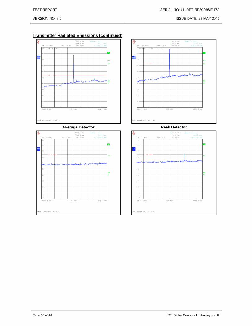
Transmitter Radiated Emissions (continued)
Average Detector
Peak Detector
Ref 100 dBµV Att 10 dB*
*
*
*
Offset 6.2 dB
1 AVMAXH
A
LVL
TDF
3DB
RBW 1 MHz
VBW 3 MHz
SWT 20 ms
AC
Start 1 GHz Stop 4 GHz300 MHz/
0
10
20
30
40
50
60
70
80
90
100
1
Marker 1 [T1 ]
45.01 dBµV
3.427884615 GHz
D1 54 dBµV
Date: 12.MAR.2013 10:32:58
Ref 100 dBµV Att 10 dB*
*
*
Offset 6.2 dB
1 PKMAXH
A
LVL
TDF
3DB
RBW 1 MHz
VBW 3 MHz
SWT 20 ms
AC
Start 1 GHz Stop 4 GHz300 MHz/
0
10
20
30
40
50
60
70
80
90
100
1
Marker 1 [T1 ]
54.87 dBµV
3.413461538 GHz
D1 74 dBµV
Date: 12.MAR.2013 10:34:10
Ref 80 dBµV Att 0 dB*
*
*
1 PKMAXH
A
TDF
3DB
RBW 1 MHz
VBW 3 MHz
SWT 20 ms
AC
Start 4 GHz Stop 6 GHz200 MHz/
-20
-10
0
10
20
30
40
50
60
70
80
1
Marker 1 [T1 ]
41.88 dBµV
4.961538462 GHz
D1 54 dBµV
Date: 11.MAR.2013 10:14:26
Ref 80 dBµV Att 0 dB*
*
*
1 PKMAXH
A
TDF
3DB
RBW 1 MHz
VBW 3 MHz
SWT 20 ms
AC
Start 6 GHz Stop 8 GHz200 MHz/
-20
-10
0
10
20
30
40
50
60
70
80
1
Marker 1 [T1 ]
52.23 dBµV
7.442307692 GHz
D1 54 dBµV
Date: 11.MAR.2013 11:07:21

TEST REPORT SERIAL NO: UL-RPT-RP89265JD17A
VERSION NO. 3.0 ISSUE DATE: 28 MAY 2013
RFI Global Services Ltd trading as UL Page 37 of 48
Transmitter Radiated Emissions (continued)
Note: These plots are pre-scans and for indication purposes only. For final measurements, see accompanying tables.
Ref 80 dBµV Att 0 dB*
*
*
1 PKMAXH
A
TDF
3DB
RBW 1 MHz
VBW 3 MHz
SWT 30 ms
AC
Start 8 GHz Stop 12.75 GHz475 MHz/
-20
-10
0
10
20
30
40
50
60
70
80
1
Marker 1 [T1 ]
47.16 dBµV
12.407451923 GHz
D1 54 dBµV
Date: 11.MAR.2013 12:07:09
Ref 80 dBµV Att 0 dB*
*
*
1 PKMAXH
A
TDF
3DB
RBW 1 MHz
VBW 3 MHz
SWT 35 ms
AC
Start 12.75 GHz Stop 18 GHz525 MHz/
-20
-10
0
10
20
30
40
50
60
70
80
1
Marker 1 [T1 ]
49.51 dBµV
17.024038462 GHz
D1 54 dBµV
Date: 11.MAR.2013 11:51:47
Ref 80 dBµV Att 0 dB*
*
*
1 PKMAXH
A
TDF
3DB
RBW 1 MHz
VBW 3 MHz
SWT 45 ms
AC
Start 18 GHz Stop 25 GHz700 MHz/
-20
-10
0
10
20
30
40
50
60
70
80
1
Marker 1 [T1 ]
48.10 dBµV
20.737179487 GHz
D1 54 dBµV
Date: 11.MAR.2013 12:11:24

TEST REPORT SERIAL NO: UL-RPT-RP89265JD17A
VERSION NO. 3.0 ISSUE DATE: 28 MAY 2013
Page 38 of 48 RFI Global Services Ltd trading as UL
Transmitter Radiated Emissions (continued) Test Equipment Used:
RFI No.
Instrument Manufacturer Type No. Serial No. Date Calibration Due
Cal. Interval (Months)
K0002 3m RSE Chamber Rainford EMC N/A N/A 04 Nov 2013 12
M1630 Test Receiver Rohde & Schwarz ESU40 100233 07 Feb 2014 12
A1534 Pre Amplifier Hewlett Packard 8449B 3008A00405 04 Nov 2013 12
A1866 Attenuator HP 8491A 016341 23 Apr 2013 12
A1818 Antenna EMCO 3115 00075692 04 Nov 2013 12
A253 Antenna Flann Microwave 12240-20 128 04 Nov 2013 12
A254 Antenna Flann Microwave 14240-20 139 04 Nov 2013 12
A255 Antenna Flann Microwave 16240-20 519 04 Nov 2013 12
A256 Antenna Flann Microwave 18240-20 400 04 Nov 2013 12
A436 Antenna Flann Microwave 20240-20 330 04 Nov 2013 12

TEST REPORT SERIAL NO: UL-RPT-RP89265JD17A
VERSION NO. 3.0 ISSUE DATE: 28 MAY 2013
RFI Global Services Ltd trading as UL Page 39 of 48
5.2.7. Transmitter Band Edge Radiated Emissions Test Summary:
Test Engineer: David Doyle Test Date: 12 March 2013
Test Sample Serial Number: Not marked or stated
FCC Reference: Parts 15.247(d) & 15.209(a)
Industry Canada Reference: RSS-Gen 4.9 / RSS-210 A8.5
Test Method Used: As detailed in ANSI C63.10 Sections 6.9.2
Environmental Conditions:
Temperature (°C): 23
Relative Humidity (%): 29
Note(s):
1. The final measured value, for the given emission, in the table below incorporates the calibrated antenna factor and cable loss.
2. * -20 dBc limit.

TEST REPORT SERIAL NO: UL-RPT-RP89265JD17A
VERSION NO. 3.0 ISSUE DATE: 28 MAY 2013
Page 40 of 48 RFI Global Services Ltd trading as UL
Transmitter Band Edge Radiated Emissions (continued) Results: Static Mode / DH5
Frequency (MHz)
Antenna Polarity
Peak Level (dBµV/m)
Limit (dBμV/m)
Margin (dB) Result
2400.0 Horizontal 68.1 86.9* 18.8 Complied
2483.5 Horizontal 67.4 74.0 6.6 Complied
Frequency
(MHz) Antenna Polarity
Average Level(dBμV/m)
Limit (dBμV/m)
Margin (dB) Result
2483.5 Horizontal 53.7 54.0 0.3 Complied
Lower Band Edge Peak Static
Upper Band Edge Peak Static
Upper Band Edge Average Static
Ref 110 dBµV Att 10 dB*
*
*
Offset 6.2 dBD1 106.9 dBµV
1 PKMAXH
A
LVL
TDF
3DB
RBW 100 kHz
VBW 300 kHz
SWT 20 ms
AC
Center 2.4 GHz Span 50 MHz5 MHz/
10
20
30
40
50
60
70
80
90
100
110
1
Marker 1 [T1 ]
68.12 dBµV
2.400000000 GHz
D1 106.9 dBµV
F1
D2 86.9 dBµV
Date: 12.MAR.2013 11:48:40
Ref 110 dBµV Att 10 dB
*
*
Offset 6.2 dB
1 PKMAXH
A
LVL
TDF
3DB
RBW 1 MHz
VBW 3 MHz
SWT 2.5 ms
AC
*
Center 2.4835 GHz Span 50 MHz5 MHz/
10
20
30
40
50
60
70
80
90
100
110
1
Marker 1 [T1 ]
67.35 dBµV
2.483500000 GHz
D1 74 dBµV
F1
Date: 12.MAR.2013 11:34:41
Ref 110 dBµV Att 10 dB*
*
*
Offset 6.2 dB
1 PKMAXH
A
LVL
TDF
3DB
RBW 1 MHz
VBW 10 Hz
SWT 5 s
AC
Center 2.4835 GHz Span 50 MHz5 MHz/
10
20
30
40
50
60
70
80
90
100
110
1
Marker 1 [T1 ]
53.66 dBµV
2.483500000 GHz
D1 54 dBµV
F1
Date: 12.MAR.2013 11:43:18

TEST REPORT SERIAL NO: UL-RPT-RP89265JD17A
VERSION NO. 3.0 ISSUE DATE: 28 MAY 2013
RFI Global Services Ltd trading as UL Page 41 of 48
Transmitter Band Edge Radiated Emissions (continued) Results: Hopping Mode / DH5
Frequency (MHz)
Antenna Polarity
Peak Level (dBµV/m)
Limit (dBμV/m)
Margin (dB) Result
2400.0 Horizontal 61.7 88.1 26.4 Complied
2483.5 Horizontal 58.9 74.0 15.1 Complied
Frequency
(MHz) Antenna Polarity
Average Level(dBμV/m)
Limit (dBμV/m)
Margin (dB) Result
2483.5 Horizontal 39.0 54.0 15.0 Complied
Lower Band Edge Peak Hopping
Upper Band Edge Peak Hopping
Upper Band Edge Average Hopping
Ref 110 dBµV Att 10 dB*
*
*
Offset 6.2 dBD1 108.1 dBµV
1 PKMAXH
A
LVL
TDF
3DB
RBW 100 kHz
VBW 300 kHz
SWT 20 ms
AC
Center 2.4 GHz Span 50 MHz5 MHz/
10
20
30
40
50
60
70
80
90
100
110
1
Marker 1 [T1 ]
61.69 dBµV
2.400000000 GHz
D1 108.1 dBµV
F1
D2 88.1 dBµV
Date: 12.MAR.2013 11:55:52
Ref 110 dBµV Att 10 dB*
*
*
Offset 6.2 dB
1 PKMAXH
A
LVL
TDF
3DB
RBW 1 MHz
VBW 3 MHz
SWT 2.5 ms
AC
Center 2.4835 GHz Span 50 MHz5 MHz/
10
20
30
40
50
60
70
80
90
100
110
1
Marker 1 [T1 ]
58.89 dBµV
2.483500000 GHz
D1 74 dBµV
F1
Date: 12.MAR.2013 12:10:37
Ref 110 dBµV Att 10 dB*
*
*
Offset 6.2 dB
1 PKMAXH
A
LVL
TDF
3DB
RBW 1 MHz
VBW 10 Hz
SWT 5 s
AC
Center 2.4835 GHz Span 50 MHz5 MHz/
10
20
30
40
50
60
70
80
90
100
110
1
Marker 1 [T1 ]
39.03 dBµV
2.483500000 GHz
D1 54 dBµV
F1
Date: 12.MAR.2013 12:11:16

TEST REPORT SERIAL NO: UL-RPT-RP89265JD17A
VERSION NO. 3.0 ISSUE DATE: 28 MAY 2013
Page 42 of 48 RFI Global Services Ltd trading as UL
Transmitter Band Edge Radiated Emissions (continued) Results: Static Mode / 2DH5
Frequency (MHz)
Antenna Polarity
Peak Level (dBµV/m)
Limit (dBμV/m)
Margin (dB) Result
2400.0 Horizontal 62.8 86.8 24.0 Complied
2483.5 Horizontal 66.8 74.0 7.2 Complied
Frequency
(MHz) Antenna Polarity
Average Level(dBμV/m)
Limit (dBμV/m)
Margin (dB) Result
2483.5 Horizontal 53.4 54.0 0.6 Complied
Lower Band Edge Peak Static
Upper Band Edge Peak Static
Upper Band Edge Average Static
Ref 110 dBµV Att 10 dB*
*
*
Offset 6.2 dBD1 106.8 dBµV
1 PKMAXH
A
LVL
TDF
3DB
RBW 100 kHz
VBW 300 kHz
SWT 20 ms
AC
Center 2.4 GHz Span 50 MHz5 MHz/
10
20
30
40
50
60
70
80
90
100
110
1
Marker 1 [T1 ]
62.77 dBµV
2.400000000 GHz
D1 106.8 dBµV
F1
D2 86.8 dBµV
Date: 12.MAR.2013 11:52:23
Ref 110 dBµV Att 10 dB*
*
*
Offset 6.2 dB
1 PKMAXH
A
LVL
TDF
3DB
RBW 1 MHz
VBW 3 MHz
SWT 2.5 ms
AC
Center 2.4835 GHz Span 50 MHz5 MHz/
10
20
30
40
50
60
70
80
90
100
110
1
Marker 1 [T1 ]
66.81 dBµV
2.483500000 GHz
D1 74 dBµV
F1
Date: 12.MAR.2013 11:39:38
Ref 110 dBµV Att 10 dB*
*
*
Offset 6.2 dB
1 PKMAXH
A
LVL
TDF
3DB
RBW 1 MHz
VBW 10 Hz
SWT 5 s
AC
Center 2.4835 GHz Span 50 MHz5 MHz/
10
20
30
40
50
60
70
80
90
100
110
1
Marker 1 [T1 ]
53.44 dBµV
2.483500000 GHz
D1 54 dBµV
F1
Date: 12.MAR.2013 11:40:26

TEST REPORT SERIAL NO: UL-RPT-RP89265JD17A
VERSION NO. 3.0 ISSUE DATE: 28 MAY 2013
RFI Global Services Ltd trading as UL Page 43 of 48
Transmitter Band Edge Radiated Emissions (continued) Results: Hopping Mode / 2DH5
Frequency (MHz)
Antenna Polarity
Peak Level (dBµV/m)
Limit (dBμV/m)
Margin (dB) Result
2400.0 Horizontal 58.6 86.7 28.1 Complied
2483.5 Horizontal 60.8 74.0 13.2 Complied
Frequency
(MHz) Antenna Polarity
Average Level(dBμV/m)
Limit (dBμV/m)
Margin (dB) Result
2483.5 Horizontal 38.4 54.0 15.6 Complied
Lower Band Edge Peak Hopping
Upper Band Edge Peak Hopping
Upper Band Edge Average Hopping
Ref 110 dBµV Att 10 dB*
*
*
Offset 6.2 dBD1 106.7 dBµV
1 PKMAXH
A
LVL
TDF
3DB
RBW 100 kHz
VBW 300 kHz
SWT 20 ms
AC
Center 2.4 GHz Span 50 MHz5 MHz/
10
20
30
40
50
60
70
80
90
100
110
1
Marker 1 [T1 ]
58.63 dBµV
2.400000000 GHz
D1 106.7 dBµV
F1
D2 86.7 dBµV
Date: 12.MAR.2013 11:57:31
Ref 110 dBµV Att 10 dB*
*
*
Offset 6.2 dB
1 PKMAXH
A
LVL
TDF
3DB
RBW 1 MHz
VBW 3 MHz
SWT 2.5 ms
AC
Center 2.4835 GHz Span 50 MHz5 MHz/
10
20
30
40
50
60
70
80
90
100
110
1
Marker 1 [T1 ]
60.77 dBµV
2.483500000 GHz
D1 74 dBµV
F1
Date: 12.MAR.2013 12:08:58
Ref 110 dBµV Att 10 dB*
*
*
Offset 6.2 dB
1 PKMAXH
A
LVL
TDF
3DB
RBW 1 MHz
VBW 10 Hz
SWT 5 s
AC
Center 2.4835 GHz Span 50 MHz5 MHz/
10
20
30
40
50
60
70
80
90
100
110
1
Marker 1 [T1 ]
38.39 dBµV
2.483500000 GHz
D1 54 dBµV
F1
Date: 12.MAR.2013 12:09:36

TEST REPORT SERIAL NO: UL-RPT-RP89265JD17A
VERSION NO. 3.0 ISSUE DATE: 28 MAY 2013
Page 44 of 48 RFI Global Services Ltd trading as UL
Transmitter Band Edge Radiated Emissions (continued) Results: Static Mode / 3DH5
Frequency (MHz)
Antenna Polarity
Peak Level (dBµV/m)
Limit (dBμV/m)
Margin (dB) Result
2400.0 Horizontal 61.0 86.9 25.9 Complied
2483.5 Horizontal 67.4 74.0 6.6 Complied
Frequency
(MHz) Antenna Polarity
Average Level(dBμV/m)
Limit (dBμV/m)
Margin (dB) Result
2483.5 Horizontal 53.7 54.0 0.3 Complied
Lower Band Edge Peak Static
Upper Band Edge Peak Static
Upper Band Edge Average Static
Ref 110 dBµV Att 10 dB*
*
*
Offset 6.2 dBD1 106.9 dBµV
1 PKMAXH
A
LVL
TDF
3DB
RBW 100 kHz
VBW 300 kHz
SWT 20 ms
AC
Center 2.4 GHz Span 50 MHz5 MHz/
10
20
30
40
50
60
70
80
90
100
110
1
Marker 1 [T1 ]
61.02 dBµV
2.400000000 GHz
D1 106.9 dBµV
F1
D2 86.9 dBµV
Date: 12.MAR.2013 11:53:34
Ref 110 dBµV Att 10 dB*
*
*
Offset 6.2 dB
1 PKMAXH
A
LVL
TDF
3DB
RBW 1 MHz
VBW 3 MHz
SWT 2.5 ms
AC
Center 2.4835 GHz Span 50 MHz5 MHz/
10
20
30
40
50
60
70
80
90
100
110
1
Marker 1 [T1 ]
67.38 dBµV
2.483500000 GHz
D1 74 dBµV
F1
Date: 12.MAR.2013 11:42:39
Ref 110 dBµV Att 10 dB*
*
*
Offset 6.2 dB
1 PKMAXH
A
LVL
TDF
3DB
RBW 1 MHz
VBW 10 Hz
SWT 5 s
AC
Center 2.4835 GHz Span 50 MHz5 MHz/
10
20
30
40
50
60
70
80
90
100
110
1
Marker 1 [T1 ]
53.66 dBµV
2.483500000 GHz
D1 54 dBµV
F1
Date: 12.MAR.2013 11:43:18

TEST REPORT SERIAL NO: UL-RPT-RP89265JD17A
VERSION NO. 3.0 ISSUE DATE: 28 MAY 2013
RFI Global Services Ltd trading as UL Page 45 of 48
Transmitter Band Edge Radiated Emissions (continued) Results: Hopping Mode / 3DH5
Frequency (MHz)
Antenna Polarity
Peak Level (dBµV/m)
Limit (dBμV/m)
Margin (dB) Result
2400.0 Horizontal 57.7 86.1* 28.4 Complied
2483.5 Horizontal 62.7 74.0 11.3 Complied
Frequency
(MHz) Antenna Polarity
Average Level(dBμV/m)
Limit (dBμV/m)
Margin (dB) Result
2483.5 Horizontal 40.9 54.0 13.1 Complied
Lower Band Edge Peak Hopping
Upper Band Edge Peak Hopping
Upper Band Edge Average Hopping
Ref 110 dBµV Att 10 dB*
*
*
Offset 6.2 dBD1 106 1 dBµV
1 PKMAXH
A
LVL
TDF
3DB
RBW 100 kHz
VBW 300 kHz
SWT 20 ms
AC
Center 2.4 GHz Span 50 MHz5 MHz/
10
20
30
40
50
60
70
80
90
100
110
1
Marker 1 [T1 ]
57.68 dBµV
2.400000000 GHz
D1 106.1 dBµV
F1
D2 86.1 dBµV
Date: 12.MAR.2013 11:59:05
Ref 110 dBµV Att 10 dB*
*
*
Offset 6.2 dB
1 PKMAXH
A
LVL
TDF
3DB
RBW 1 MHz
VBW 3 MHz
SWT 2.5 ms
AC
Center 2.4835 GHz Span 50 MHz5 MHz/
10
20
30
40
50
60
70
80
90
100
110
1
Marker 1 [T1 ]
62.71 dBµV
2.483500000 GHz
D1 74 dBµV
F1
Date: 12.MAR.2013 12:00:33
Ref 110 dBµV Att 10 dB*
*
*
Offset 6.2 dB
1 PKMAXH
A
LVL
TDF
3DB
RBW 1 MHz
VBW 10 Hz
SWT 5 s
AC
Center 2.4835 GHz Span 50 MHz5 MHz/
10
20
30
40
50
60
70
80
90
100
110
1
Marker 1 [T1 ]
40.89 dBµV
2.483500000 GHz
D1 54 dBµV
F1
Date: 12.MAR.2013 12:07:56

TEST REPORT SERIAL NO: UL-RPT-RP89265JD17A
VERSION NO. 3.0 ISSUE DATE: 28 MAY 2013
Page 46 of 48 RFI Global Services Ltd trading as UL
Transmitter Band Edge Radiated Emissions (continued) Test Equipment Used:
RFI No.
Instrument Manufacturer Type No. Serial No. Date Calibration Due
Cal. Interval (Months)
K0002 3m RSE Chamber Rainford EMC N/A N/A 04 Nov 2013 12
M1630 Test Receiver Rohde & Schwarz ESU40 100233 07 Feb 2014 12
A1534 Pre Amplifier Hewlett Packard 8449B 3008A00405 04 Nov 2013 12
A1818 Antenna EMCO 3115 00075692 04 Nov 2013 12
A1866 Attenuator HP 8491A 016341 23 Apr 2013 12

TEST REPORT SERIAL NO: UL-RPT-RP89265JD17A
VERSION NO. 3.0 ISSUE DATE: 28 MAY 2013
RFI Global Services Ltd trading as UL Page 47 of 48
6. Measurement Uncertainty No measurement or test can ever be perfect and the imperfections give rise to error of measurement in the results. Consequently the result of a measurement is only an approximation to the value of the measurand (the specific quantity subject to measurement) and is only complete when accompanied by a statement of the uncertainty of the approximation.
The expression of uncertainty of a measurement result allows realistic comparison of results with reference values and limits given in specifications and standards.
The uncertainty of the result may need to be taken into account when interpreting the measurement results.
The reported expanded uncertainties below are based on a standard uncertainty multiplied by an appropriate coverage factor such that a confidence level of approximately 95% is maintained. For the purposes of this document “approximately” is interpreted as meaning “effectively” or “for most practical purposes”.
Measurement Type Range Confidence Level (%)
Calculated Uncertainty
Conducted Maximum Peak Output Power 2.4 GHz to 2.4835 GHz 95% ±1.13 dB
Carrier Frequency Separation 2.4 GHz to 2.4835 GHz 95% ±0.92 ppm
Average Time of Occupancy 2.4 GHz to 2.4835 GHz 95% ±0.3 ns
20 dB Bandwidth 2.4 GHz to 2.4835 GHz 95% ±0.92 ppm
Radiated Spurious Emissions 30 MHz to 26.5 GHz 95% ±2.94 dB
The methods used to calculate the above uncertainties are in line with those recommended within the various measurement specifications. Where measurement specifications do not include guidelines for the evaluation of measurement uncertainty the published guidance of the appropriate accreditation body is followed.

TEST REPORT SERIAL NO: UL-RPT-RP89265JD17A
VERSION NO. 3.0 ISSUE DATE: 28 MAY 2013
Page 48 of 48 RFI Global Services Ltd trading as UL
7. Report Revision History Version Number
Revision Details
Page No(s) Clause Details
1.0 - - Initial Version
2.0 - - Update to Industry Canada certification number
3.0 - - Update to location of testing address